Embed Size (px)
Citation preview
1
New Product
Digital TimerH5CX-@-N
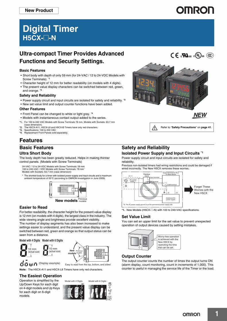
Ultra-compact Timer Provides Advanced Functions and Security Settings.
Basic Features• Short body with depth of only 59 mm (for 24-VAC / 12 to 24-VDC Models with
Screw Terminals). *1
• Character height of 12 mm for better readability (on models with 4 digits).• The present value display characters can be switched between red, green,
and orange. *2
Safety and Reliability• Power supply circuit and input circuits are isolated for safety and reliability. *3
• New set value limit and output counter functions have been added.
Other Features• Front Panel can be changed to white or light gray. *4 • Models with instantaneous contact output added to the series.
*1. For 100 to 240 VAC Models with Screw Terminals 78 mm, Models with Sockets: 63.7 mm (case dimension).
*2. The H5CX-A11, H5CX-L8 and H5CX-B Timers have only red characters.*3. Specifications: 100 to 240 VAC*4. Replacement Front Panels sold separately.
FeaturesBasic FeaturesUltra Short BodyThe body depth has been greatly reduced. Helps in making thinner control panels. (Models with Screw Terminals)
Easier to ReadFor better readability, the character height for the present value display is 12 mm (on models with 4 digits), the largest class in the industry. The wide viewing angle and brightness provide excellent visibility.The number of display segments has also been increased to make settings easier to understand, and the present value display can be switched between red, green and orange so that output status can be seen from a distance.
Note: The H5CX-A11 and H5CX-L8 Timers have only red characters.
The Easiest OperationOperation is simplified by the Up/Down Keys for each digit on 4-digit models and Up Keys for each digit on 6-digit models.
Safety and ReliabilityIsolated Power Supply and Input Circuits *1Power supply circuit and input circuits are isolated for safety and reliability. Previous non-isolated timers had wiring restrictions and could be damaged if wired incorrectly. The New H5CX removes these worries.
*1. New Models (H5CX-@-N) with 100 to 240-VAC specifications.
Set Value LimitYou can set an upper limit for the set value to prevent unexpected operation of output devices caused by setting mistakes.
Output CounterThe output counter counts the number of times the output turns ON (alarm display, count monitoring, count in increments of 1,000). This counter is useful in managing the service life of the Timer or the load.
Refer to “Safety Precautions” on page 41.
New models Previous models
24-VAC / 12 to 24-VDC Models with Screw Terminals: 59 mm100 to 240-VAC / VDC Models with Screw Terminals: 78 mm *
Models with Sockets: 63.7 mm (case dimension)
* The shortest body for a timer with isolated power supply and input circuits and a maximum ambient temperature of 55°C (according to OMRON investigation in June 2009).
Model with 4 Digits Model with 6 Digits
(Display example)
12 mm(actual size)
10 mm(actual size) Previous
modelsNew
models
Easy to read from the top, bottom, and sides!
Model with 4 Digits Model with 6 Digits
–V +V
Output terminal on PLC or other device
AC power supply *2
H5CXPrevious
Input terminal
0-V terminal
COM terminal
Forget These Worries with the New H5CX
Stabilized DC power supply
*2. The AC power supply ground is on the commercial power supply side.
Worry-free operation is achieved with the New H5CX by restricting the time that can be set.
H5CX-@-N
2
Other FeaturesChange the Front Panel ColorThe Front Panel can be replaced with an optional Front Panel (order separately) with a different color to match the installation site. Select from black, white, and light gray.
Models with Instantaneous Contact OutputModels with instantaneous contact outputs have been added to the lineup for use with self-holding circuits and as auxiliary relays. These models are also convenient when replacing analog timers.
Universal NPN/PNP InputDC 2-wire sensors can be connected for a wide range of input devices.
Waterproof, Dust-proof Structure (UL508 Type 4X and IP66)Worry-free application is possible in locations subject to water.Note: When the Y92S-29 Waterproof Packing is used.
Key ProtectionSelect from any of seven protection patterns. Use the best one for the application.
New ModesModes, such as a stopwatch mode (Mode S), have been added. Select any of 15 modes.
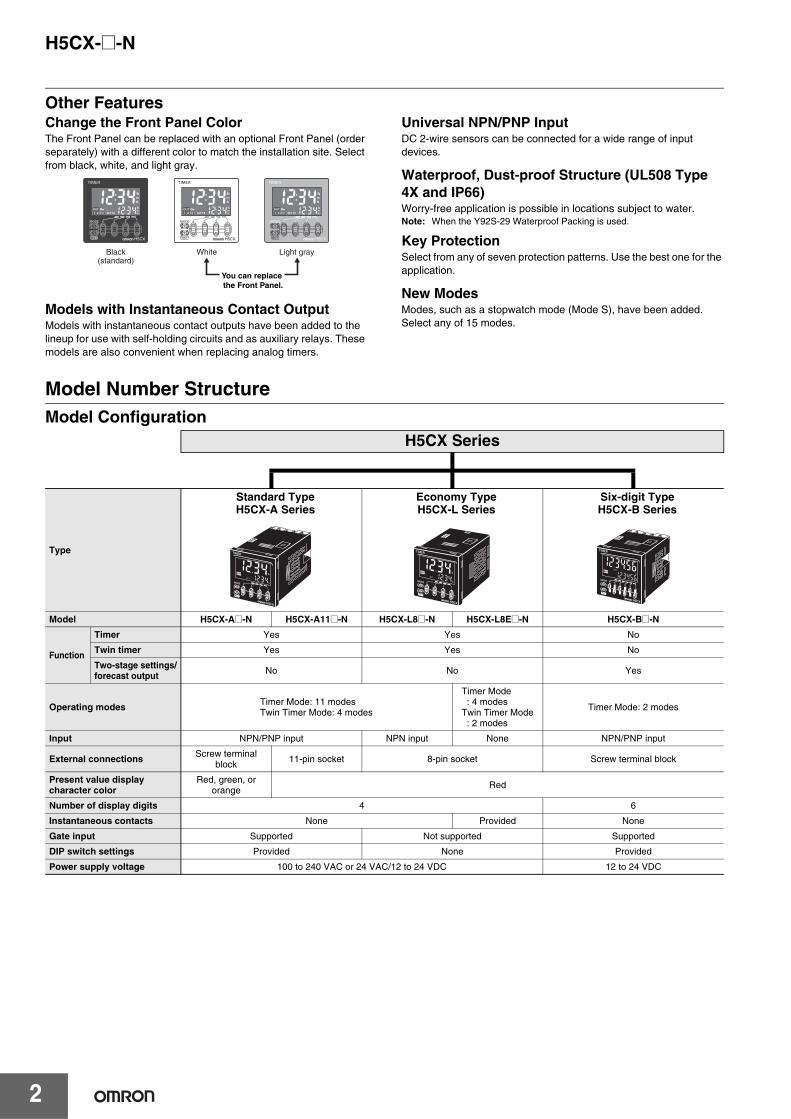
Model Number StructureModel Configuration
Black(standard)
White Light gray
You can replace the Front Panel.
H5CX Series
Type
Standard TypeH5CX-A Series
Economy TypeH5CX-L Series
Six-digit TypeH5CX-B Series
Model H5CX-A@-N H5CX-A11@-N H5CX-L8@-N H5CX-L8E@-N H5CX-B@-N
Function
Timer Yes Yes No
Twin timer Yes Yes No
Two-stage settings/forecast output No No Yes
Operating modes Timer Mode: 11 modesTwin Timer Mode: 4 modes
Timer Mode : 4 modesTwin Timer Mode : 2 modes
Timer Mode: 2 modes
Input NPN/PNP input NPN input None NPN/PNP input
External connections Screw terminal block 11-pin socket 8-pin socket Screw terminal block
Present value display character color
Red, green, or orange Red
Number of display digits 4 6
Instantaneous contacts None Provided None
Gate input Supported Not supported Supported
DIP switch settings Provided None Provided
Power supply voltage 100 to 240 VAC or 24 VAC/12 to 24 VDC 12 to 24 VDC
H5CX-@-N
3
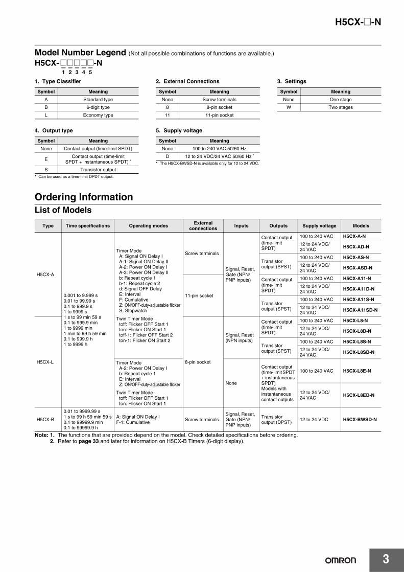
Model Number Legend (Not all possible combinations of functions are available.)
H5CX- @@@@@-N– – – – –1 2 3 4 5
Ordering InformationList of Models
Note: 1. The functions that are provided depend on the model. Check detailed specifications before ordering.2. Refer to page 33 and later for information on H5CX-B Timers (6-digit display).
Type Time specifications Operating modes External connections Inputs Outputs Supply voltage Models
H5CX-A
0.001 to 9.999 s0.01 to 99.99 s0.1 to 999.9 s1 to 9999 s1 s to 99 min 59 s0.1 to 999.9 min1 to 9999 min1 min to 99 h 59 min0.1 to 999.9 h1 to 9999 h
Timer ModeA: Signal ON Delay I A-1: Signal ON Delay IIA-2: Power ON Delay IA-3: Power ON Delay IIb: Repeat cycle 1b-1: Repeat cycle 2d: Signal OFF DelayE: IntervalF: CumulativeZ: ON/OFF-duty-adjustable flickerS: Stopwatch
Twin Timer Modetoff: Flicker OFF Start 1ton: Flicker ON Start 1toff-1: Flicker OFF Start 2ton-1: Flicker ON Start 2
Screw terminals
Signal, Reset, Gate (NPN/PNP inputs)
Contact output (time-limit SPDT)
100 to 240 VAC H5CX-A-N
12 to 24 VDC/24 VAC H5CX-AD-N
Transistor output (SPST)
100 to 240 VAC H5CX-AS-N
12 to 24 VDC/24 VAC H5CX-ASD-N
11-pin socket
Contact output (time-limit SPDT)
100 to 240 VAC H5CX-A11-N
12 to 24 VDC/24 VAC H5CX-A11D-N
Transistor output (SPST)
100 to 240 VAC H5CX-A11S-N
12 to 24 VDC/24 VAC H5CX-A11SD-N
H5CX-L 8-pin socket
Signal, Reset (NPN inputs)
Contact output (time-limit SPDT)
100 to 240 VAC H5CX-L8-N
12 to 24 VDC/24 VAC H5CX-L8D-N
Transistor output (SPST)
100 to 240 VAC H5CX-L8S-N
12 to 24 VDC/24 VAC
H5CX-L8SD-N
Timer ModeA-2: Power ON Delay Ib: Repeat cycle 1E: IntervalZ: ON/OFF-duty-adjustable flicker
Twin Timer Modetoff: Flicker OFF Start 1ton: Flicker ON Start 1
None
Contact output (time-limit SPDT + instantaneous SPDT)Models with instantaneous contact outputs
100 to 240 VAC H5CX-L8E-N
12 to 24 VDC/24 VAC H5CX-L8ED-N
H5CX-B
0.01 to 9999.99 s1 s to 99 h 59 min 59 s0.1 to 99999.9 min0.1 to 99999.9 h
A: Signal ON Delay IF-1: Cumulative Screw terminals
Signal, Reset, Gate (NPN/PNP inputs)
Transistor output (DPST) 12 to 24 VDC H5CX-BWSD-N
4. Output type
* Can be used as a time-limit DPDT output.
5. Supply voltage
* The H5CX-BWSD-N is available only for 12 to 24 VDC.
Symbol Meaning
None Contact output (time-limit SPDT)
EContact output (time-limit
SPDT + instantaneous SPDT) *
S Transistor output
Symbol Meaning
None 100 to 240 VAC 50/60 Hz
D 12 to 24 VDC/24 VAC 50/60 Hz *
1. Type Classifier 2. External Connections 3. Settings
Symbol Meaning
A Standard type
B 6-digit type
L Economy type
Symbol Meaning
None Screw terminals
8 8-pin socket
11 11-pin socket
Symbol Meaning
None One stage
W Two stages
H5CX-@-N
4
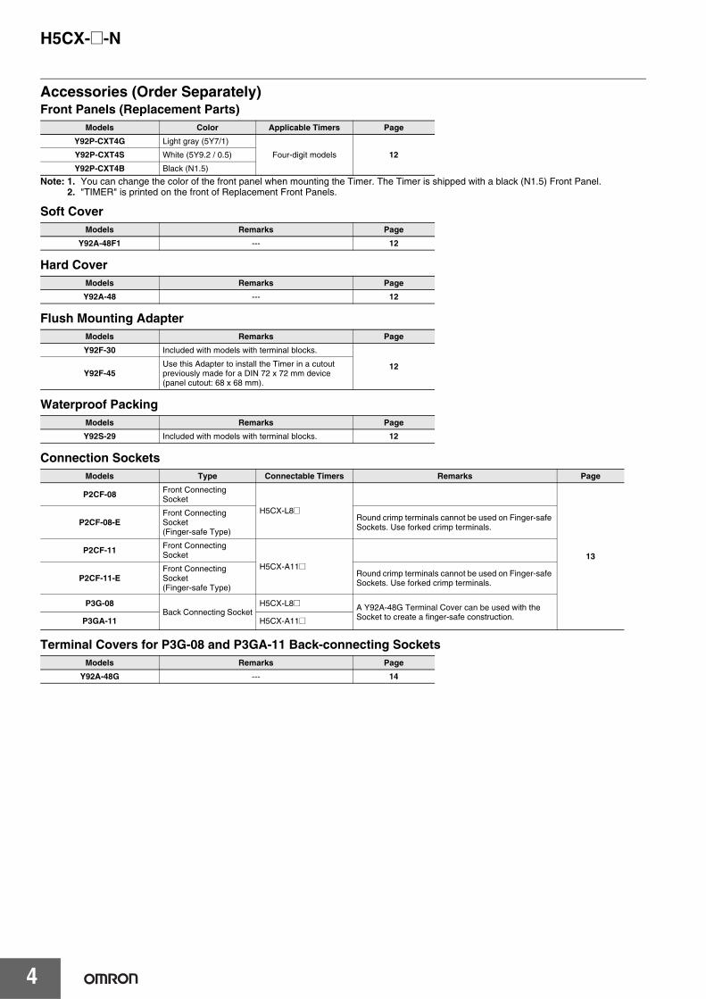
Accessories (Order Separately)Front Panels (Replacement Parts)
Note: 1. You can change the color of the front panel when mounting the Timer. The Timer is shipped with a black (N1.5) Front Panel.2. "TIMER" is printed on the front of Replacement Front Panels.
Soft Cover
Hard Cover
Flush Mounting Adapter
Waterproof Packing
Connection Sockets
Terminal Covers for P3G-08 and P3GA-11 Back-connecting Sockets
Models Color Applicable Timers Page
Y92P-CXT4G Light gray (5Y7/1)
Four-digit models 12Y92P-CXT4S White (5Y9.2 / 0.5)
Y92P-CXT4B Black (N1.5)
Models Remarks Page
Y92A-48F1 --- 12
Models Remarks Page
Y92A-48 --- 12
Models Remarks Page
Y92F-30 Included with models with terminal blocks.
12Y92F-45
Use this Adapter to install the Timer in a cutout previously made for a DIN 72 x 72 mm device (panel cutout: 68 x 68 mm).
Models Remarks Page
Y92S-29 Included with models with terminal blocks. 12
Models Type Connectable Timers Remarks Page
P2CF-08 Front Connecting Socket
H5CX-L8@
13
P2CF-08-EFront Connecting Socket(Finger-safe Type)
Round crimp terminals cannot be used on Finger-safe Sockets. Use forked crimp terminals.
P2CF-11 Front Connecting Socket
H5CX-A11@P2CF-11-E
Front Connecting Socket(Finger-safe Type)
Round crimp terminals cannot be used on Finger-safe Sockets. Use forked crimp terminals.
P3G-08Back Connecting Socket
H5CX-L8@ A Y92A-48G Terminal Cover can be used with the Socket to create a finger-safe construction.P3GA-11 H5CX-A11@
Models Remarks Page
Y92A-48G --- 14
H5CX-A@-N/-L@-N
5
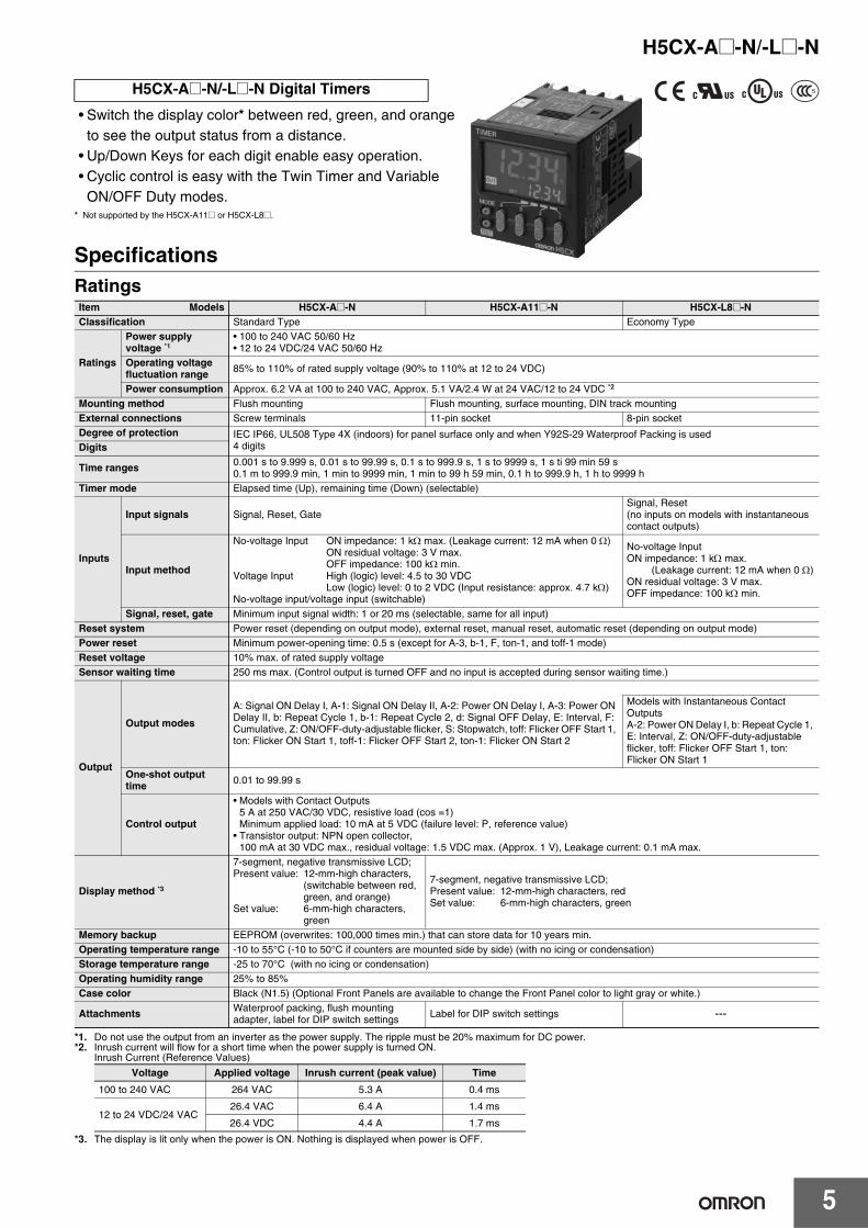
• Switch the display color* between red, green, and orange to see the output status from a distance.
• Up/Down Keys for each digit enable easy operation. • Cyclic control is easy with the Twin Timer and Variable
ON/OFF Duty modes.* Not supported by the H5CX-A11@ or H5CX-L8@.
SpecificationsRatings
*1. Do not use the output from an inverter as the power supply. The ripple must be 20% maximum for DC power.*2. Inrush current will flow for a short time when the power supply is turned ON.
Inrush Current (Reference Values)
*3. The display is lit only when the power is ON. Nothing is displayed when power is OFF.
H5CX-A@-N/-L@-N Digital Timers
Item Models H5CX-A@-N H5CX-A11@-N H5CX-L8@-NClassification Standard Type Economy Type
Ratings
Power supply voltage *1
• 100 to 240 VAC 50/60 Hz• 12 to 24 VDC/24 VAC 50/60 Hz
Operating voltage fluctuation range 85% to 110% of rated supply voltage (90% to 110% at 12 to 24 VDC)
Power consumption Approx. 6.2 VA at 100 to 240 VAC, Approx. 5.1 VA/2.4 W at 24 VAC/12 to 24 VDC *2
Mounting method Flush mounting Flush mounting, surface mounting, DIN track mountingExternal connections Screw terminals 11-pin socket 8-pin socketDegree of protection IEC IP66, UL508 Type 4X (indoors) for panel surface only and when Y92S-29 Waterproof Packing is used
4 digitsDigits
Time ranges 0.001 s to 9.999 s, 0.01 s to 99.99 s, 0.1 s to 999.9 s, 1 s to 9999 s, 1 s ti 99 min 59 s0.1 m to 999.9 min, 1 min to 9999 min, 1 min to 99 h 59 min, 0.1 h to 999.9 h, 1 h to 9999 h
Timer mode Elapsed time (Up), remaining time (Down) (selectable)
Inputs
Input signals Signal, Reset, GateSignal, Reset (no inputs on models with instantaneous contact outputs)
Input method
No-voltage Input ON impedance: 1 kΩ max. (Leakage current: 12 mA when 0 Ω)ON residual voltage: 3 V max.OFF impedance: 100 kΩ min.
Voltage Input High (logic) level: 4.5 to 30 VDCLow (logic) level: 0 to 2 VDC (Input resistance: approx. 4.7 kΩ)
No-voltage input/voltage input (switchable)
No-voltage InputON impedance: 1 kΩ max.
(Leakage current: 12 mA when 0 Ω)ON residual voltage: 3 V max.OFF impedance: 100 kΩ min.
Signal, reset, gate Minimum input signal width: 1 or 20 ms (selectable, same for all input) Reset system Power reset (depending on output mode), external reset, manual reset, automatic reset (depending on output mode)Power reset Minimum power-opening time: 0.5 s (except for A-3, b-1, F, ton-1, and toff-1 mode)Reset voltage 10% max. of rated supply voltage Sensor waiting time 250 ms max. (Control output is turned OFF and no input is accepted during sensor waiting time.)
Output
Output modes
A: Signal ON Delay I, A-1: Signal ON Delay II, A-2: Power ON Delay I, A-3: Power ON Delay II, b: Repeat Cycle 1, b-1: Repeat Cycle 2, d: Signal OFF Delay, E: Interval, F: Cumulative, Z: ON/OFF-duty-adjustable flicker, S: Stopwatch, toff: Flicker OFF Start 1, ton: Flicker ON Start 1, toff-1: Flicker OFF Start 2, ton-1: Flicker ON Start 2
Models with Instantaneous Contact OutputsA-2: Power ON Delay I, b: Repeat Cycle 1, E: Interval, Z: ON/OFF-duty-adjustable flicker, toff: Flicker OFF Start 1, ton: Flicker ON Start 1
One-shot output time 0.01 to 99.99 s
Control output
• Models with Contact Outputs5 A at 250 VAC/30 VDC, resistive load (cos =1)Minimum applied load: 10 mA at 5 VDC (failure level: P, reference value)
• Transistor output: NPN open collector,100 mA at 30 VDC max., residual voltage: 1.5 VDC max. (Approx. 1 V), Leakage current: 0.1 mA max.
Display method *3
7-segment, negative transmissive LCD;Present value: 12-mm-high characters,
(switchable between red, green, and orange)
Set value: 6-mm-high characters, green
7-segment, negative transmissive LCD;Present value: 12-mm-high characters, red Set value: 6-mm-high characters, green
Memory backup EEPROM (overwrites: 100,000 times min.) that can store data for 10 years min.Operating temperature range -10 to 55°C (-10 to 50°C if counters are mounted side by side) (with no icing or condensation)Storage temperature range -25 to 70°C (with no icing or condensation) Operating humidity range 25% to 85%Case color Black (N1.5) (Optional Front Panels are available to change the Front Panel color to light gray or white.)
Attachments Waterproof packing, flush mounting adapter, label for DIP switch settings Label for DIP switch settings ---
Voltage Applied voltage Inrush current (peak value) Time
100 to 240 VAC 264 VAC 5.3 A 0.4 ms
12 to 24 VDC/24 VAC26.4 VAC 6.4 A 1.4 ms
26.4 VDC 4.4 A 1.7 ms
H5CX-A@-N/-L@-N
6
Characteristics
* Refer to Life-test Curve.
Accuracy of operating time and setting error (including temperature and voltage influences)
Power-ON start: ±0.01% ±50 ms max. (See note 1.)Signal start: ±0.005%±0.03 ms max. (See note 1.)Signal start for transistor output model: ±0.005%±3 ms max. (See note 1 and 2.)If the set value is within the sensor waiting time at startup the control output of the H5CX will not turn ON until the sensor waiting time passes.Note: 1. The values are based on the set value.
2. The value is applied for a minimum pulse width of 1 ms.
Insulation resistance100 MΩ min. (at 500 VDC) between current-carrying terminal and exposed non-current-carrying metal parts, and between non-continuous contacts
Dielectric strength
2,000 VAC, 50/60 Hz for 1 min between current-carrying metal parts and non-current-carrying metal parts2,000 VAC, 50/60 Hz for 1 min between power supply and input circuits for H5CX-A11-N/-A11S-N1,000 VAC, 50/60 Hz for 1 min between control output, power supply, and input circuits for H5CX-@SD-N2,000 VAC, 50/60 Hz for 1 min between control output, power supply, and input circuits for other models1,000 VAC, 50/60 Hz for 1 min between non-continuous contacts
Impulse withstand voltage
3 kV (between power terminals) for 100 to 240 VAC, 1 kV for 24 VAC/12 to 24 VDC4.5 kV (between current-carrying terminal and exposed non-current-carrying metal parts) for 100 to 240 VAC 1.5 kV for 24 VAC/12 to 24 VDC
Noise immunity±1.5 kV (between power terminals) and ±600 V (between input terminals), square-wave noise by noise simulator (pulse width: 100 ns/1 µs, 1-ns rise)
Static immunity Malfunction: 8 kVDestruction: 15 kV
Vibration resistance
Destruction 10 to 55 Hz with 0.75-mm single amplitude each in three directions for 2 h each
Malfunction 10 to 55 Hz with 0.35-mm single amplitude each in three directions for 10 min each
Shock resistance
Destruction 300 m/s2 in three directions, three cycles
Malfunction 100 m/s2 in three directions, three cycles
Life expectancy
Mechanical 10,000,000 operations min. (under no load at 18,000 operations/h and ambient temperature of 23°C)
Electrical 100,000 operations min. (5 A at 250 VAC, resistive load at 1,800 operations/h and ambient temperature of 23°C) *
Weight Approx. 115 g (Timer only)
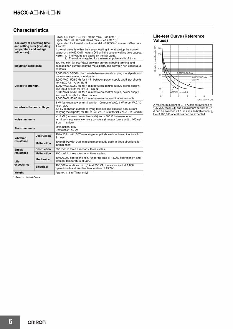
Life-test Curve (Reference Values)
A maximum current of 0.15 A can be switched at 125 VDC (cosφ =1) and a maximum current of 0.1 A can be switched if L/R is 7 ms. In both cases, a life of 100,000 operations can be expected.
DC30V L/R=7ms
AC250V/DC30Vcosφ =1
AC250V cosφ =0.4
0 1 2 3 4 5
1,000
500
100
50
10
Sw
itchi
ng o
pera
tions
(×
104 )
Load current (A)
H5CX-A@-N/-L@-N
7
Applicable Standards
*1. The following safety standards apply to models with sockets (H5CX-A11@ or H5CX-L8@).cUL (Listing): Applicable when an OMRON P2CF (-E) Socket is used. cUR (Recognition): Applicable when any other socket is used.
*2. Excluding the H5CX-ASD-N/-A11SD-N/-L8SD-N.
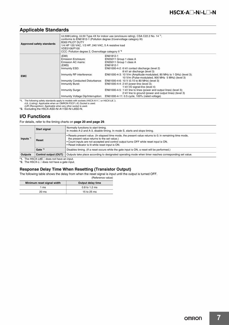
I/O FunctionsFor details, refer to the timing charts on page 20 and page 29.
*1. The H5CX-L8E@ does not have an input.*2. The H5CX-L@ does not have a gate input.
Response Delay Time When Resetting (Transistor Output)The following table shows the delay from when the reset signal is input until the output is turned OFF.
(Reference value)
Approved safety standards
UL508/Listing, UL50 Type 4X for indoor use (enclosure rating), CSA C22.2 No. 14 *1, conforms to EN61812-1 (Pollution degree 2/overvoltage category III)B300 PILOT DUTY1/4 HP 120 VAC, 1/3 HP, 240 VAC, 5 A resistive loadVDE0106/P100 CCC: Pollution degree 2, Overvoltage category II *2
EMC
(EMI) EN61812-1Emission Enclosure: EN55011 Group 1 class AEmission AC mains: EN55011 Group 1 class A(EMS) EN61812-1Immunity ESD: EN61000-4-2: 6 kV contact discharge (level 2)
8 kV air discharge (level 3)Immunity RF-interference: EN61000-4-3: 10 V/m (Amplitude-modulated, 80 MHz to 1 GHz) (level 3);
10 V/m (Pulse-modulated, 900 MHz 5 MHz) (level 3)Immunity Conducted Disturbance: EN61000-4-6: 10 V (0.15 to 80 MHz) (level 3) Immunity Burst: EN61000-4-4: 2 kV power-line (level 3);
1 kV I/O signal-line (level 4) Immunity Surge: EN61000-4-5: 1 kV line to lines (power and output lines) (level 3);
2 kV line to ground (power and output lines) (level 3)Immunity Voltage Dip/Interruption: EN61000-4-11: 0.5 cycle, 100% (rated voltage)
Inputs *1
Start signal Normally functions to start timing. In modes A-2 and A-3, disable timing. In mode S, starts and stops timing.
Reset
• Resets present value. (In elapsed time mode, the present value returns to 0; in remaining time mode, the present value returns to the set value.)
• Count inputs are not accepted and control output turns OFF while reset input is ON.• Reset indicator is lit while reset input is ON.
Gate *2 Disables timing. (If a reset occurs while the gate input is ON, a reset will be performed.)
Outputs Control output (OUT) Outputs take place according to designated operating mode when timer reaches corresponding set value.
Minimum reset signal width Output delay time
1 ms 0.8 to 1.2 ms
20 ms 15 to 25 ms
H5CX-A@-N/-L@-N
8
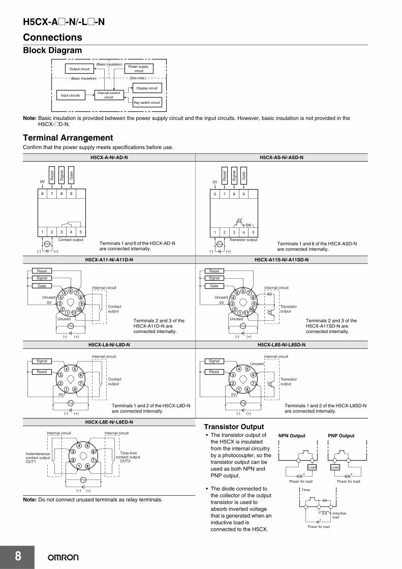
ConnectionsBlock Diagram
Note: Basic insulation is provided between the power supply circuit and the input circuits. However, basic insulation is not provided in the H5CX-@D-N.
Terminal ArrangementConfirm that the power supply meets specifications before use.
H5CX-A-N/-AD-N H5CX-AS-N/-ASD-N
H5CX-A11-N/-A11D-N H5CX-A11S-N/-A11SD-N
H5CX-L8-N/-L8D-N H5CX-L8S-N/-L8SD-N
H5CX-L8E-N/-L8ED-N
Note: Do not connect unused terminals as relay terminals.
Output circuit
(See note.)
Internal control circuit
Display circuit
Key switch circuit
Input circuits
Power supply circuit
(Basic insulation)
(Basic insulation)
6 7 8 9
0V
1 2 3 4 5
(-) (+)
Contact output
Res
et
Sig
nal
Gat
e
Terminals 1 and 6 of the H5CX-AD-N are connected internally.
6 7 8 9
0V
1 2 3 4 5
(-) (+)
Transistor output
Res
et
Sig
nal
Gat
eTerminals 1 and 6 of the H5CX-ASD-N are connected internally.
6 78
910
1112
3
45
0V
Reset
Signal
Gate Internal circuit
Unused
Unused
Contact output
(-) (+)
Terminals 2 and 3 of the H5CX-A11D-N are connected internally.
6 78
910
1112
3
45
0V
Reset
Signal
Gate Internal circuit
Unused
Unused
Transistor output
(-) (+)
Terminals 2 and 3 of the H5CX-A11SD-N are connected internally.
4
3
2
1 8
7
6
5
0V
Signal
Reset
Internal circuit
Contact output
(-) (+)
Terminals 1 and 2 of the H5CX-L8D-N are connected internally.
4
3
2
1 8
7
6
5
0V
Signal
Reset
Internal circuit
Unused
Transistor output
(-) (+)
Terminals 1 and 2 of the H5CX-L8SD-N are connected internally.
Transistor Output• The transistor output of
the H5CX is insulated from the internal circuitry by a photocoupler, so the transistor output can be used as both NPN and PNP output.
• The diode connected to the collector of the output transistor is used to absorb inverted voltage that is generated when an inductive load is connected to the H5CX.
Power for load
+
Load
Power for load
+
Load
NPN Output PNP Output
Power for load
+
Timer
Inductive load
4
3
2
1 8
7
6
5
(–) (+)
Internal circuit Internal circuit
Instantaneous contact outputOUT1
Time-limit contact output OUT2
H5CX-A@-N/-L@-N
9
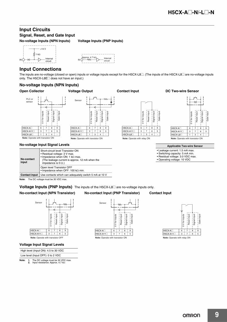
Input CircuitsSignal, Reset, and Gate Input
Input ConnectionsThe inputs are no-voltage (closed or open) inputs or voltage inputs except for the H5CX-L8@. (The inputs of the H5CX-L8@ are no-voltage inputs only. The H5CX-L8E@ does not have an input.)
No-voltage Inputs (NPN Inputs)
Voltage Inputs (PNP Inputs) The inputs of the H5CX-L8@ are no-voltage inputs only.
Voltage Input Signal Levels
Note: 1. The DC voltage must be 30 VDC max.2. Input resistance: Approx. 4.7 kΩ
Open Collector Voltage Output Contact Input DC Two-wire Sensor
No-contact Input (NPN Transistor) No-contact Input (PNP Transistor) Contact Input
High level (Input ON): 4.5 to 30 VDC
Low level (Input OFF): 0 to 2 VDC
Internal circuit
IN
+14 V
1 kΩ
Internal circuitIN
Approx. 4.7 kΩ
No-voltage Inputs (NPN Inputs) Voltage Inputs (PNP Inputs)
H5CX-A@
-
H5CX-A11@H5CX-L8@
6 7 8 9
3 7 6 5
1 3 4
PLC or sensor
Note: Operate with transistor ON
0 V
for
inpu
ts
Res
et in
put
Sig
nal i
nput
Gat
e in
put
H5CX-A@H5CX-A11@H5CX-L8@ -
6 7 8 9
3 7 6 5
1 3 4
Sensor
Note: Operate with transistor ON
0 V
for
inpu
ts
Res
et in
put
Sig
nal i
nput
Gat
e in
put
H5CX-A@
-
H5CX-A11@H5CX-L8@
6 7 8 9
3 7 6 5
1 3 4
Note: Operate with relay ON
0 V
for
inpu
ts
Res
et in
put
Sig
nal i
nput
Gat
e in
put
H5CX-A@
-
H5CX-A11@H5CX-L8@
6 7 8 9
3 7 6 5
1 3 4
Note: Operate with transistor ON
0 V
for
inpu
ts
Res
et in
put
Sig
nal i
nput
Gat
e in
put
Applicable Two-wire Sensor
• Leakage current: 1.5 mA max.• Switching capacity: 5 mA min.• Residual voltage: 3.0 VDC max.• Operating voltage: 10 VDC
No-voltage Input Signal Levels
Note: The DC voltage must be 30 VDC max.
No-contact input
Short-circuit level Transistor ON• Residual voltage: 3 V max.• Impedance when ON: 1 kΩ max.
(The leakage current is approx. 12 mA when the impedance is 0 Ω.)
Open level Transistor OFF• Impedance when OFF: 100 kΩ min.
Contact input Use contacts which can adequately switch 5 mA at 10 V
H5CX-A@H5CX-A11@
6 7 8 9
3 7 6 5
Sensor
Note: Operate with transistor OFF
0 V
for
inpu
ts
Res
et in
put
Sig
nal i
nput
Gat
e in
put
H5CX-A@H5CX-A11@
6 7 8 9
3 7 6 5
Sensor
Note: Operate with transistor ON
0 V
for
inpu
ts
Res
et in
put
Sig
nal i
nput
Gat
e in
put
H5CX-A@H5CX-A11@
6 7 8 9
3 7 6 5
Note: Operate with relay ON
0 V
for
inpu
ts
Res
et in
put
Sig
nal i
nput
Gat
e in
put
H5CX-A@-N/-L@-N
10
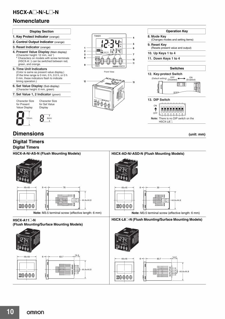
Nomenclature
Dimensions (unit: mm)
Digital TimersDigital Timers
OFF
ON
12mm 6mm
1
32
8
9
5
4
6
7
10
11
12 13
Display Section
1. Key Protect Indicator (orange)
2. Control Output Indicator (orange)
Front View
Note: There is no DIP switch on the H5CX-L8@.
Character Size for Present Value Display
Character Size for Set Value Display
3. Reset Indicator (orange)
Operation Key
Switches
8. Mode Key (Changes modes and setting items)
9. Reset Key (Resets present value and output)
10. Up Keys 1 to 4
11. Down Keys 1 to 4
12. Key-protect Switch
13. DIP Switch
6. Set Value Display (Sub-display) (Character height: 6 mm, green)
7. Set Value 1, 2 Indicator (green)
4. Present Value Display (Main display) (Character height: 12 mm, red *) * Characters on models with screw terminals
(H5CX-A@) can be switched between red, green, and orange.
5. Time Unit Indicators (Color is same as present value display.) (If the time range is 0 min, 0 h, 0.0 h, or 0 h
0 min, these indicators flash to indicate timing operation.)
1 2 3 4 5 6 7 8
OFF(Disabled)
ON(Enabled)
(Default setting)
786
44.8×44.8
48×48
H5CX-A-N/-AS-N (Flush Mounting Models)
Note: M3.5 terminal screw (effective length: 6 mm)
596
44.8×44.8
48×48
H5CX-AD-N/-ASD-N (Flush Mounting Models)
Note: M3.5 terminal screw (effective length: 6 mm)
63.714.4
6
44.8×44.8
48×48
H5CX-A11@-N(Flush Mounting/Surface Mounting Models)
H5CX-L8@-N (Flush Mounting/Surface Mounting Models)
63.714.2
6
44.8×44.8
48×48
H5CX-A@-N/-L@-N
11
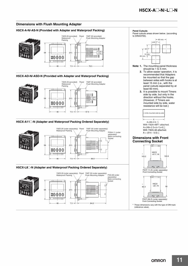
Dimensions with Flush Mounting Adapter
58
48 76.57.5
(51)
Y92S-29 (provided) Waterproof Packing
Y92F-30 (provided) Flush Mounting Adapter
Panel
H5CX-A-N/-AS-N (Provided with Adapter and Waterproof Packing) Panel CutoutsPanel cutouts areas shown below. (according to DIN43700).
Note: 1. The mounting panel thickness should be 1 to 5 mm.
2. To allow easier operation, it is recommended that Adapters be mounted so that the gap between sides with hooks is at least 15 mm (i.e., with the panel cutouts separated by at least 60 mm).
3. It is possible to mount Timers side by side, but only in the direction without the hooks. (However, if Timers are mounted side by side, water resistance will be lost.)
Dimensions with Front Connecting Socket
* These dimensions vary with the type of DIN track (reference value).
60 min.
60 min.
45+0.6 0
45+0.6 0
15 min.
AA=(48n-2.5)
With Y92A-48F1 attached.A={48n-2.5+(n-1)×4}With Y92A-48 attached.A = (51n - 5.5)
n Units mounted side-by-side
+1–0
+1–0
+1–0
103.2 100.9
H5CX-A11@-N
P2CF-11(-E) (order separately)Front Connecting Socket
*
H5CX-L8@-N
P2CF-08(-E) (order separately) Front Connecting Socket
92.3 90*
58
48 57.57.5
(51)
Y92S-29 (provided) Waterproof Packing
Y92F-30 (provided) Flush Mounting Adapter
Panel
H5CX-AD-N/-ASD-N (Provided with Adapter and Waterproof Packing)
58
48 89.97.5
(51)
Y92S-29 (order separately) Waterproof Packing
Y92F-30 (order separately) Flush Mounting Adapter
P3GA-11 (order separately) Back-connecting Socket
Panel
H5CX-A11@-N (Adapter and Waterproof Packing Ordered Separately)
H5CX-L8@-N (Adapter and Waterproof Packing Ordered Separately)
58
48 84.87.5
(51)
Y92F-30 (order separately) Flush Mounting Adapter P3G-08 (order
separately) Back-connecting Socket
PanelY92S-29 (order separately) Waterproof Packing
H5CX-A@-N/-L@-N
12
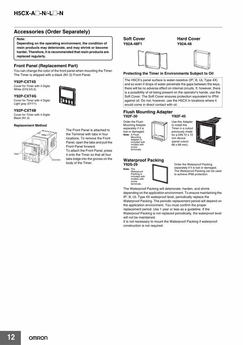
Accessories (Order Separately)
Front Panel (Replacement Part)You can change the color of the front panel when mounting the Timer.The Timer is shipped with a black (N1.5) Front Panel. Protecting the Timer in Environments Subject to Oil
The Waterproof Packing will deteriorate, harden, and shrink depending on the application environment. To ensure maintaining the IP@6, UL Type 4X waterproof level, periodically replace the Waterproof Packing. The periodic replacement period will depend on the application environment. You must confirm the proper replacement period. Use 1 year or less as a guideline. If the Waterproof Packing is not replaced periodically, the waterproof level will not be maintained. It is not necessary to mount the Waterproof Packing if waterproof construction is not required.
Note:Depending on the operating environment, the condition of resin products may deteriorate, and may shrink or become harder. Therefore, it is recommended that resin products are replaced regularly.
Y92P-CXT4SCover for Timer with 4 DigitsWhite (5Y9.2/0.5)
Y92P-CXT4GCover for Timer with 4 DigitsLight gray (5Y7/1)
Y92P-CXT4BCover for Timer with 4 DigitsBlack (N1.5)
Replacement MethodThe Front Panel is attached to the Terminal with tabs in four locations. To remove the Front Panel, open the tabs and pull the Front Panel forward. To attach the Front Panel, press it onto the Timer so that all four tabs lodge into the groves on the body of the Timer.
Tabs
Grooves
The H5CX's panel surface is water-resistive (IP@6, UL Type 4X) and so even if drops of water penetrate the gaps between the keys, there will be no adverse effect on internal circuits. If, however, there is a possibility of oil being present on the operator's hands, use the Soft Cover. The Soft Cover ensures protection equivalent to IP54 against oil. Do not, however, use the H5CX in locations where it would come in direct contact with oil.
Soft CoverY92A-48F1
Hard CoverY92A-48
Y92F-45Use this Adapter to install the Timer in a cutout previously made for a DIN 72 x 72 mm device (panel cutout: 68 x 68 mm).
Flush Mounting AdapterY92F-30Order the Flush Mounting Adapter separately if it is lost or damaged.Note: A Flush
Mounting Adapter is included with models with screw terminals.
Waterproof PackingY92S-29Note: The
Waterproof Packing is included with models with screw terminals.
Order the Waterproof Packing separately if it is lost or damaged.The Waterproof Packing can be used to achieve IP66 protection.
H5CX-A@-N/-L@-N
13
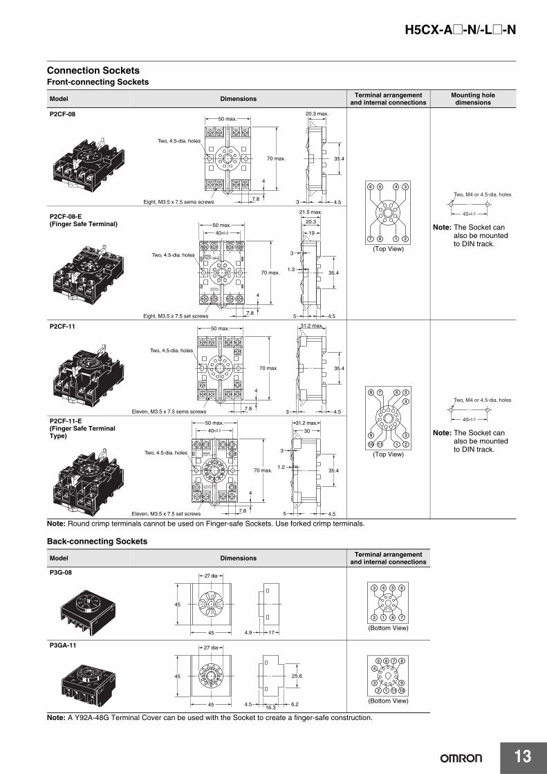
Connection SocketsFront-connecting Sockets
Note: Round crimp terminals cannot be used on Finger-safe Sockets. Use forked crimp terminals.
Back-connecting Sockets
Note: A Y92A-48G Terminal Cover can be used with the Socket to create a finger-safe construction.
Model Dimensions Terminal arrangement and internal connections
Mounting hole dimensions
P2CF-08
(Top View)
Note: The Socket can also be mounted to DIN track.
P2CF-08-E (Finger Safe Terminal)
P2CF-11
(Top View)
Note: The Socket can also be mounted to DIN track.
P2CF-11-E (Finger Safe Terminal Type)
Model Dimensions Terminal arrangement and internal connections
P3G-08
(Bottom View)
P3GA-11
(Bottom View)
4
70 max.
Two, 4.5-dia. holes
Eight, M3.5 x 7.5 sems screws 7.8
20.3 max.
4.53
50 max.
35.4
6 5 4 3
7 8 1 2
40±0.2
Two, M4 or 4.5-dia. holes
1 27 8
4 36 5
P2CF-08-E
10A250VACRESISTIVE
4
70 max.
Two, 4.5-dia. holes
Eight, M3.5 x 7.5 set screws 7.8
21.5 max.
20.3
19
4.5
35.41.3
3
5
50 max.
40±0.2
4
70 max.
50 max.
Two, 4.5-dia. holes
Eleven, M3.5 x 7.5 sems screws 7.8
31.2 max.
4.53
35.4
8 7 6 5
10 11 1 2
9 3
4
40±0.2
Two, M4 or 4.5-dia. holes
10 11 1 2
78 6 5
3
4
9
P2CF-11-E
10A250VACRESISTIVE
4
70 max.
50 max.
40±0.2
Two, 4.5-dia. holes
Eleven, M3.5 x 7.5 set screws 7.8
31.2 max.
30
4.5
35.41.2
3
5
27 dia
4.9 17
45
45
6543
7812
27 dia
4.516.3
6.2
25.645
45
876
4
3 9
5
101112
H5CX-A@-N/-L@-N
14
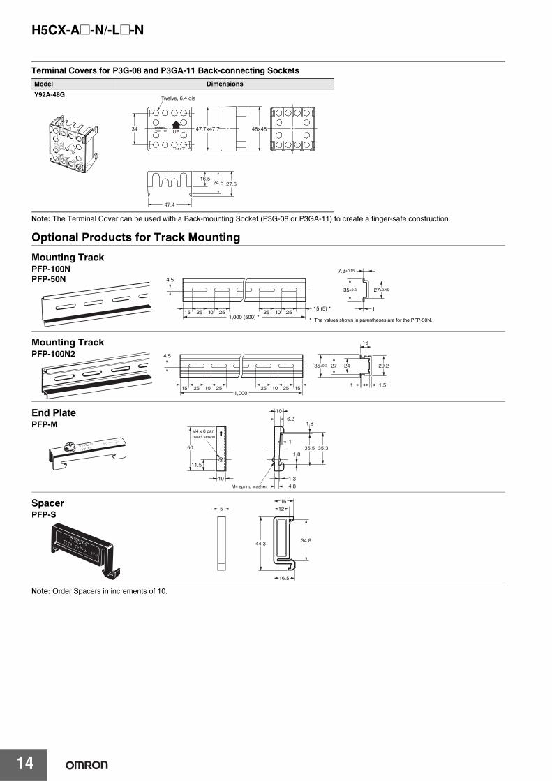
Terminal Covers for P3G-08 and P3GA-11 Back-connecting Sockets
Note: The Terminal Cover can be used with a Back-mounting Socket (P3G-08 or P3GA-11) to create a finger-safe construction.
Optional Products for Track Mounting
Note: Order Spacers in increments of 10.
Model Dimensions
Y92A-48G
Y92A-48G UP
P C
34
Twelve, 6.4 dia
47.7×47.7 48×48
27.6 24.6 16.5
47.4
1
35±0.3
7.3±0.15
27±0.15
4.5
15 25 251015 (5) *
1025 251,000 (500) * * The values shown in parentheses are for the PFP-50N.
Mounting TrackPFP-100NPFP-50N
15 25 251,000
4.5
25 25 15101
242735±0.3
16
1.5
29.2
10
Mounting TrackPFP-100N2
4.81.3
35.5 35.3
1.8
1
1.8
10
6.2
M4 spring washer
50
11.5
M4 x 8 pan head screw
10
End PlatePFP-M
516
12
44.334.8
16.5
SpacerPFP-S
H5CX-A@-N/-L@-N
15
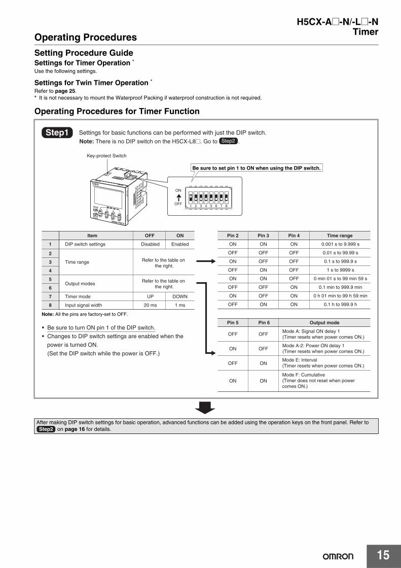
TimerOperating Procedures
Setting Procedure GuideSettings for Timer Operation *Use the following settings.
Settings for Twin Timer Operation *Refer to page 25.* It is not necessary to mount the Waterproof Packing if waterproof construction is not required.
Operating Procedures for Timer Function
After making DIP switch settings for basic operation, advanced functions can be added using the operation keys on the front panel. Refer to on page 16 for details.
Key-protect Switch
1 2 3 4 5 6 7 8OFF
ON
Disabled Enabled ON
OFF
ON
OFF
ON
OFF
ON
OFF
ON
OFF
OFF
ON
ON
OFF
OFF
ON
ON
OFF
OFF
OFF
OFF
ON
ON
ON
Refer to the table on the right.
Refer to the table on the right.
DIP switch settings
Time range
Output modes
Timer mode
Input signal width
UP DOWN
20 ms 1 ms
0.001 s to 9.999 s
0.01 s to 99.99 s
0.1 s to 999.9 s
1 s to 9999 s
0 min 01 s to 99 min 59 s
0.1 min to 999.9 min
0 h 01 min to 99 h 59 min
0.1 h to 999.9 h
OFF
ON
OFF
ON
OFF
OFF
ON
ON
Mode A: Signal ON delay 1(Timer resets when power comes ON.)
Mode A-2: Power ON delay 1 (Timer resets when power comes ON.)
Mode E: Interval (Timer resets when power comes ON.)
Mode F: Cumulative (Timer does not reset when power comes ON.)
Note: All the pins are factory-set to OFF.
� Be sure to turn ON pin 1 of the DIP switch.
� Changes to DIP switch settings are enabled when the
power is turned ON.
(Set the DIP switch while the power is OFF.)
Step1Step2
Settings for basic functions can be performed with just the DIP switch. Note: There is no DIP switch on the H5CX-L8@. Go to .
Be sure to set pin 1 to ON when using the DIP switch.
Item OFF ON Time rangePin 4Pin 3Pin 2
1
2
3
4
5
6
7
8
Pin 6 Output modePin 5
Step2
H5CX-A@-N/-L@-N
16
Timer
Run mode
Power ON
Function setting mode
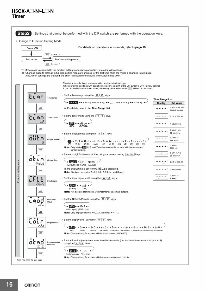
� Set the time range using the keys.
� Set the timer mode using the keys.
� Set the output mode using the keys.
� Set the input signal width using the keys.
� Set the NPN/PNP mode using the keys.
� Set the display color using the keys.
� Set the function (instantaneous or time-limit operation) for the instantaneous output (output 1) using the Keys.
� Set each digit for the output time using the corresponding keys.
For details, refer to the Time Range List.
(If the output time is set to 0.00, is displayed.)
*1. If the mode is switched to the function setting mode during operation, operation will continue.*2. Changes made to settings in function setting mode are enabled for the first time when the mode is changed to run mode. Also, when settings are changed, the timer is reset (time initialized and output turned OFF).
Display Set Value
Time Range List
0.01 s to 99.99 s
(default setting)
0.1 s to 999.9 s
1 s to 9999 s
0 min 01 s to
99 min 59 s
0.1 min to
999.9 min
1 min to
9999 min
0 h 01 min to
99 h 59 min
0.1 h to 999.9 h
1 h to 9999 h
0.001 s to
9.999 s
~
Time range
Timer mode
Output modes
Output time
Input signal
NPN/PNP input
Display color
Instantaneous/time-limit
To next pageFrom next page
s s h s
(DOWN)(UP)
(1ms)(20ms)
(A-1) (A-2) (A-3) (b-1)(b) (d) (E) (F) (S)(Z)(A)
(0.01s) (99.99s)(Output hold)
Note: Displayed for modes A, A-1, A-2, A-3, b, b-1 and S only.
Note: Only modes A-2, b, E, and Z can be selected for models with instantaneous contact outputs.
(PNP input)(NPN input)
Note: Only displayed for the H5CX-A@ and H5CX-A11@.
(Red) (Green) (Orange) (Red-green) (Green-red) (Red-orange) (Orange-red) (Green-orange)(Orange-green)
Note: Displayed only for models with terminal screws (H5CX-A@).
Note: Displayed only for models with instantaneous contact outputs.
3 s min. *2
3 s min. *1
The characters displayed in reverse video are the default settings.When performing settings with operation keys only, set pin1 of the DIP switch to OFF (factory setting).If pin 1 of the DIP switch is set to ON, the setting items indicated in will not be displayed.
(Instantaneous) (Time-limit)
Step2 Settings that cannot be performed with the DIP switch are performed with the operation keys.
• Change to Function Setting Mode.
Note: Not displayed for models with instantaneous contact outputs.
Fun
ctio
n se
tting
mod
e
……s
20ms 1ms
pnp
grn
2c1c1c
red org r-g g-r r-o o-r g-o o-g
npn
downup
za-1a a-2
99.990.01hold
hold
a-3 b b-1 d e f s
For details on operations in run mode, refer to page 19.
H5CX-A@-N/-L@-N
17
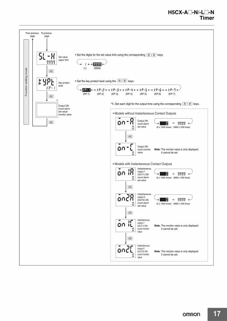
Timer
*1
To previous page
From previous page
Output ON count alarm set value/monitor value
Key protect level
Set value upper limit
(KP-1) (KP-2) (KP-3) (KP-4) (KP-5) (KP-6) (KP-7)
Instantaneous output 1 (OUT1) ON count alarm set value
Instantaneous output 2 (OUT2) ON count alarm set value
(9999 x 1000 times)(0 x 1000 times)
(9999 x 1000 times)(0 x 1000 times)
Note: The monitor value is only displayed. It cannot be set.
Output ON count alarm set value
Output ON count monitor value
(9999 x 1000 times)(0 x 1000 times)
Note: The monitor value is only displayed. It cannot be set.
Note: The monitor value is only displayed. It cannot be set.
Instantaneous output 1 (OUT1) ON count monitor value
Instantaneous output 2 (OUT2) ON count monitor value
(9999)(1)
99990
99990
99990
9999
kp-2kp-1 kp-3 kp-4 kp-5 kp-6 kp-7
1
• Models without Instantaneous Contact Outputs
• Models with Instantaneous Contact Outputs
Funct
ion s
ettin
g m
ode
� Set the digits for the set value limit using the corresponding keys.
� Set the key protect level using the keys.
*1. Set each digit for the output time using the corresponding keys.
~
~
~
H5CX-A@-N/-L@-N
18
Timer
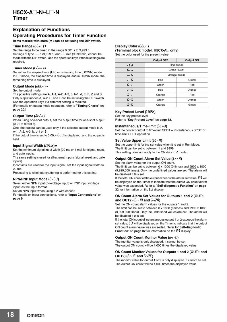
Explanation of FunctionsOperating Procedures for Timer FunctionItems marked with stars ( ) can be set using the DIP switch.
Time Range (timr)Set the range to be timed in the range 0.001 s to 9,999 h.Settings of type ---- h (9,999 h) and ---- min (9,999 min) cannot be made with the DIP switch. Use the operation keys if these settings are required.
Timer Mode (timm)Set either the elapsed time (UP) or remaining time (DOWN) mode.In UP mode, the elapsed time is displayed, and in DOWN mode, the remaining time is displayed.
Output Mode (outm)Set the output mode.The possible settings are A, A-1, A-2, A-3, b, b-1, d, E, F, Z and S. Only output modes A, A-2, E, and F can be set using the DIP switch. Use the operation keys if a different setting is required.(For details on output mode operation, refer to "Timing Charts" on page 20.)
Output Time (otim)When using one-shot output, set the output time for one-shot output (0.01 to 99.99 s). One-shot output can be used only if the selected output mode is A, A-1, A-2, A-3, b, b-1 or S. If the output time is set to 0.00, hold is displayed, and the output is held.
Input Signal Width (iflt)Set the minimum signal input width (20 ms or 1 ms) for signal, reset, and gate inputs. The same setting is used for all external inputs (signal, reset, and gate inputs). If contacts are used for the input signal, set the input signal width to 20 ms. Processing to eliminate chattering is performed for this setting.
NPN/PNP Input Mode (imod)Select either NPN input (no-voltage input) or PNP input (voltage input) as the input format.Set an NPN input when using a 2-wire sensor. For details on input connections, refer to "Input Connections" on page 9.
Display Color (colr) (Terminal block model: H5CX-A@ only)Set the color used for the present value.
Key Protect Level (kypt)Set the key protect level.Refer to “Key Protect Level” on page 32.
Instantaneous/Time-limit (otmd)Set the contact output to time-limit SPDT + instantaneous SPDT or time-limit SPDT operation.
Set Value Upper Limit (sl-h)Set the upper limit for the set value when it is set in Run Mode. The limit can be set to between 1 and 9999. This setting does not apply to the ON duty in Z mode.
Output ON Count Alarm Set Value (on-a)Set the alarm value for the output ON count. The limit can be set to between 0 x 1000 (0 times) and 9999 x 1000 (9,999,000 times). Only the underlined values are set. The alarm will be disabled if 0 is set.If the total ON count of the output exceeds the alarm set value, e3 will be displayed on the Timer to indicate that the output ON count alarm value was exceeded. Refer to “Self-diagnostic Function” on page 32 for information on the e3 display.
ON Count Alarm Set Values for Outputs 1 and 2 (OUT1 and OUT2) (on1a and on2a)Set the ON count alarm values for the outputs 1 and 2.The limit can be set to between 0 x 1000 (0 times) and 9999 x 1000 (9,999,000 times). Only the underlined values are set. The alarm will be disabled if 0 is set.If the total ON count of instantaneous output 1 or 2 exceeds the alarm set value, e3 will be displayed on the Timer to indicate that the output ON count alarm value was exceeded. Refer to “Self-diagnostic Function” on page 32 for information on the e3 display.
Output ON Count Monitor Value (on-c)The monitor value is only displayed. It cannot be set. The output ON count will be 1,000 times the displayed value.
ON Count Monitor Values for Outputs 1 and 2 (OUT1 and OUT2) (on1c and on2c)The monitor value for output 1 or 2 is only displayed. It cannot be set. The output ON count will be 1,000 times the displayed value.
Output OFF Output ON
red Red (fixed)
grn Green (fixed)
org Orange (fixed)
r-g Red Green
g-r Green Red
r-o Red Orange
o-r Orange Red
g-o Green Orange
o-g Orange Green
H5CX-A@-N/-L@-N
19
Timer
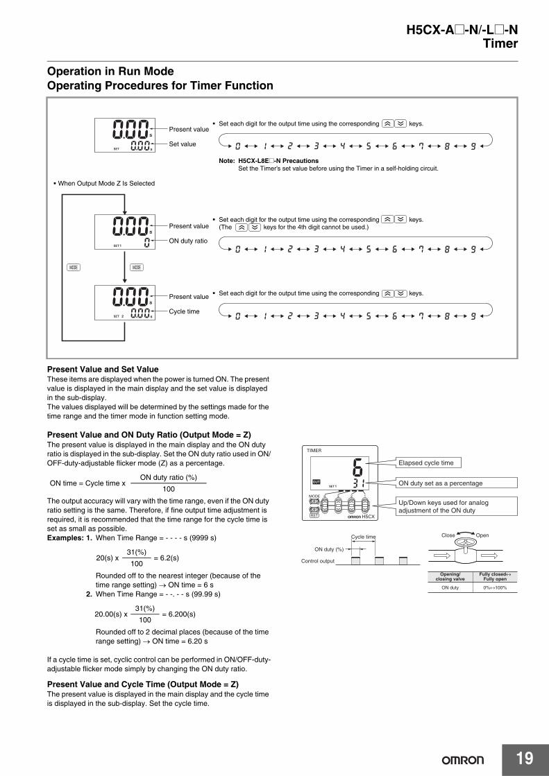
Operation in Run ModeOperating Procedures for Timer Function
Present Value and Set ValueThese items are displayed when the power is turned ON. The present value is displayed in the main display and the set value is displayed in the sub-display.The values displayed will be determined by the settings made for the time range and the timer mode in function setting mode.
Present Value and ON Duty Ratio (Output Mode = Z)The present value is displayed in the main display and the ON duty ratio is displayed in the sub-display. Set the ON duty ratio used in ON/OFF-duty-adjustable flicker mode (Z) as a percentage.
The output accuracy will vary with the time range, even if the ON duty ratio setting is the same. Therefore, if fine output time adjustment is required, it is recommended that the time range for the cycle time is set as small as possible. Examples: 1. When Time Range = - - - - s (9999 s)
Rounded off to the nearest integer (because of the time range setting) → ON time = 6 s
2. When Time Range = - -. - - s (99.99 s)
Rounded off to 2 decimal places (because of the time range setting) → ON time = 6.20 s
If a cycle time is set, cyclic control can be performed in ON/OFF-duty-adjustable flicker mode simply by changing the ON duty ratio.
Present Value and Cycle Time (Output Mode = Z)The present value is displayed in the main display and the cycle time is displayed in the sub-display. Set the cycle time.
Present value
Set value
Present value
ON duty ratio
Present value
Cycle time
� Set each digit for the output time using the corresponding keys.
Note: H5CX-L8E@-N PrecautionsSet the Timer’s set value before using the Timer in a self-holding circuit.
� Set each digit for the output time using the corresponding keys. (The keys for the 4th digit cannot be used.)
� Set each digit for the output time using the corresponding keys.
� When Output Mode Z Is Selected
ON time = Cycle time xON duty ratio (%)
100
20(s) x31(%)
= 6.2(s)100
20.00(s) x31(%)
= 6.200(s)100
Elapsed cycle time
ON duty set as a percentage
Up/Down keys used for analog adjustment of the ON duty
ON duty (%)
Cycle time
Control output
OpenClose
Opening/closing valve
ON duty
Fully closed↔Fully open
0%↔100%
H5CX-A@-N/-L@-N
20
Timer
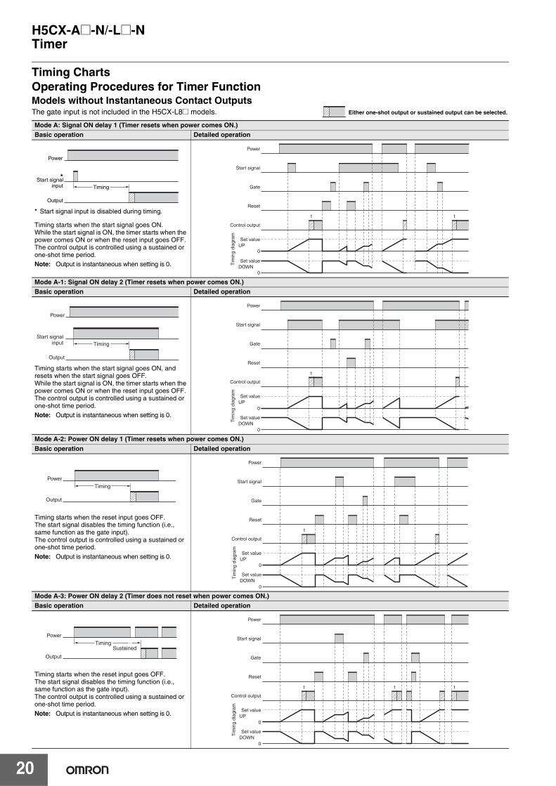
Timing ChartsOperating Procedures for Timer FunctionModels without Instantaneous Contact OutputsThe gate input is not included in the H5CX-L8@ models. Either one-shot output or sustained output can be selected.
Mode A: Signal ON delay 1 (Timer resets when power comes ON.)Basic operation Detailed operation
* Start signal input is disabled during timing.
Timing starts when the start signal goes ON.While the start signal is ON, the timer starts when the power comes ON or when the reset input goes OFF. The control output is controlled using a sustained or one-shot time period. Note: Output is instantaneous when setting is 0.
Mode A-1: Signal ON delay 2 (Timer resets when power comes ON.) Basic operation Detailed operation
Timing starts when the start signal goes ON, and resets when the start signal goes OFF.While the start signal is ON, the timer starts when the power comes ON or when the reset input goes OFF. The control output is controlled using a sustained or one-shot time period. Note: Output is instantaneous when setting is 0.
Mode A-2: Power ON delay 1 (Timer resets when power comes ON.) Basic operation Detailed operation
Timing starts when the reset input goes OFF.The start signal disables the timing function (i.e., same function as the gate input). The control output is controlled using a sustained or one-shot time period.Note: Output is instantaneous when setting is 0.
Mode A-3: Power ON delay 2 (Timer does not reset when power comes ON.)Basic operation Detailed operation
Timing starts when the reset input goes OFF. The start signal disables the timing function (i.e., same function as the gate input). The control output is controlled using a sustained or one-shot time period. Note: Output is instantaneous when setting is 0.
Power
Output
*Start signal input Timing
Power
Start signal
Gate
t t
Reset
Control output
Set value
0
Set value
UP
DOWN0
Tim
ing
diag
ram
Power
Output
Start signal input Timing
t
0
0
Power
Start signal
Gate
Reset
Control output
Set value
Set value
UP
DOWN
Tim
ing
diag
ram
Power
Output
Timing
t
0
0
Power
Start signal
Gate
Reset
Control output
Set value
Set value
UP
DOWN
Tim
ing
diag
ram
Power
Output
TimingSustained
t t t
0
0
Power
Start signal
Gate
Reset
Control output
Set value
Set value
UP
DOWN
Tim
ing
diag
ram
H5CX-A@-N/-L@-N
21
Timer
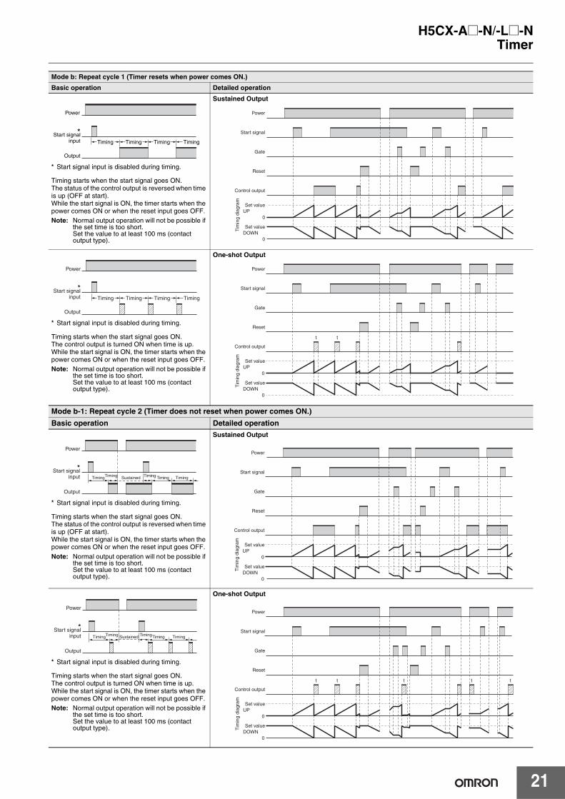
Mode b: Repeat cycle 1 (Timer resets when power comes ON.)
Basic operation Detailed operation
* Start signal input is disabled during timing.
Timing starts when the start signal goes ON.The status of the control output is reversed when time is up (OFF at start). While the start signal is ON, the timer starts when the power comes ON or when the reset input goes OFF. Note: Normal output operation will not be possible if
the set time is too short.Set the value to at least 100 ms (contact output type).
Sustained Output
* Start signal input is disabled during timing.
Timing starts when the start signal goes ON.The control output is turned ON when time is up. While the start signal is ON, the timer starts when the power comes ON or when the reset input goes OFF. Note: Normal output operation will not be possible if
the set time is too short. Set the value to at least 100 ms (contact output type).
One-shot Output
Mode b-1: Repeat cycle 2 (Timer does not reset when power comes ON.)
Basic operation Detailed operation
* Start signal input is disabled during timing.
Timing starts when the start signal goes ON.The status of the control output is reversed when time is up (OFF at start). While the start signal is ON, the timer starts when the power comes ON or when the reset input goes OFF. Note: Normal output operation will not be possible if
the set time is too short. Set the value to at least 100 ms (contact output type).
Sustained Output
* Start signal input is disabled during timing.
Timing starts when the start signal goes ON.The control output is turned ON when time is up. While the start signal is ON, the timer starts when the power comes ON or when the reset input goes OFF. Note: Normal output operation will not be possible if
the set time is too short. Set the value to at least 100 ms (contact output type).
One-shot Output
Power
Output
*Start signal input Timing Timing Timing Timing
0
0
Power
Start signal
Gate
Reset
Control output
Set value
Set value
UP
DOWNT
imin
g di
agra
m
Power
Output
*Start signal input Timing Timing Timing Timing
t t
0
0
Power
Start signal
Gate
Reset
Control output
Set value
Set value
UP
DOWN
Tim
ing
diag
ram
Power
Output
*Start signal input Timing Timing TimingTiming Sustained Timing
0
0
Power
Start signal
Gate
Reset
Control output
Set value
Set value
UP
DOWN
Tim
ing
diag
ram
Power
Output
*Start signal input Timing Timing TimingTiming Sustained Timing
t t t tt
0
0
Power
Start signal
Gate
Reset
Control output
Set value
Set value
UP
DOWN
Tim
ing
diag
ram
H5CX-A@-N/-L@-N
22
Timer
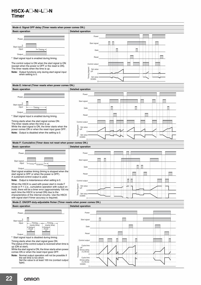
Mode d: Signal OFF delay (Timer resets when power comes ON.)
Basic operation Detailed operation
* Start signal input is enabled during timing.
The control output is ON when the start signal is ON (except when the power is OFF or the reset is ON). The timer resets when the time is up. Note: Output functions only during start signal input
when setting is 0.
Mode E: Interval (Timer resets when power comes ON.)
Basic operation Detailed operation
* Start signal input is enabled during timing.
Timing starts when the start signal comes ON.The timer resets when the time is up. While the start signal is ON, the timer starts when the power comes ON or when the reset input goes OFF. Note: Output is disabled when the setting is 0.
Mode F: Cumulative (Timer does not reset when power comes ON.)
Basic operation Detailed operation
Start signal enables timing (timing is stopped when the start signal is OFF or when the power is OFF).A sustained control output is used.Note: Output is instantaneous when setting is 0.
When the H5CX is used with power start in mode F mode or F-1 (i.e., cumulative operation with output on hold), there will be a timer error (approximately 100 ms each time the H5CX is turned ON) due to the characteristics of the internal circuitry. Use the H5CX with signal start if timer accuracy is required.
Mode Z: ON/OFF-duty-adjustable flicker (Timer resets when power comes ON.)
Basic operation Detailed operation
* Start signal input is disabled during timing.
Timing starts when the start signal goes ON.The status of the control output is reversed when time is up (ON at start). While the start signal is ON, the timer starts when power comes ON or when the reset input goes OFF. Note: Normal output operation will not be possible if
the set time is too short.Set the value to at least 100 ms (contact output type).
Output
*Start signal input Timing
Power
0
0
Power
Start signal
Gate
Reset
Control output
Set value
Set value
UP
DOWN
Tim
ing
diag
ram
Power
Output
*Start signal input Timing
0
0
Power
Start signal
Gate
Reset
Control output
Set value
Set value
UP
DOWN
Tim
ing
diag
ram
Power
Output
Start signal input Timing Sustained
Timing
0
0
Power
Start signal
Gate
Reset
Control output
Set value
Set value
UP
DOWN
Tim
ing
diag
ram
Power
Output
*Start signal input Timing
(cycle time)TimingON duty
(%)
Timing(cycle time)
TimingON duty
(%)
Power
Start signal
Gate
Reset
Control output
Cycle time
ON duty setting (%) ON time
0
Cycle timeON duty setting
(%) ON time
UP
DOWN0
Tim
ing
diag
ram
H5CX-A@-N/-L@-N
23
Timer
Models with Instantaneous Contact Outputs Either one-shot output or sustained output can be selected.
Note: H5CX-L8E@-N PrecautionsSet the Timer’s set value before using the Timer in a self-holding circuit.
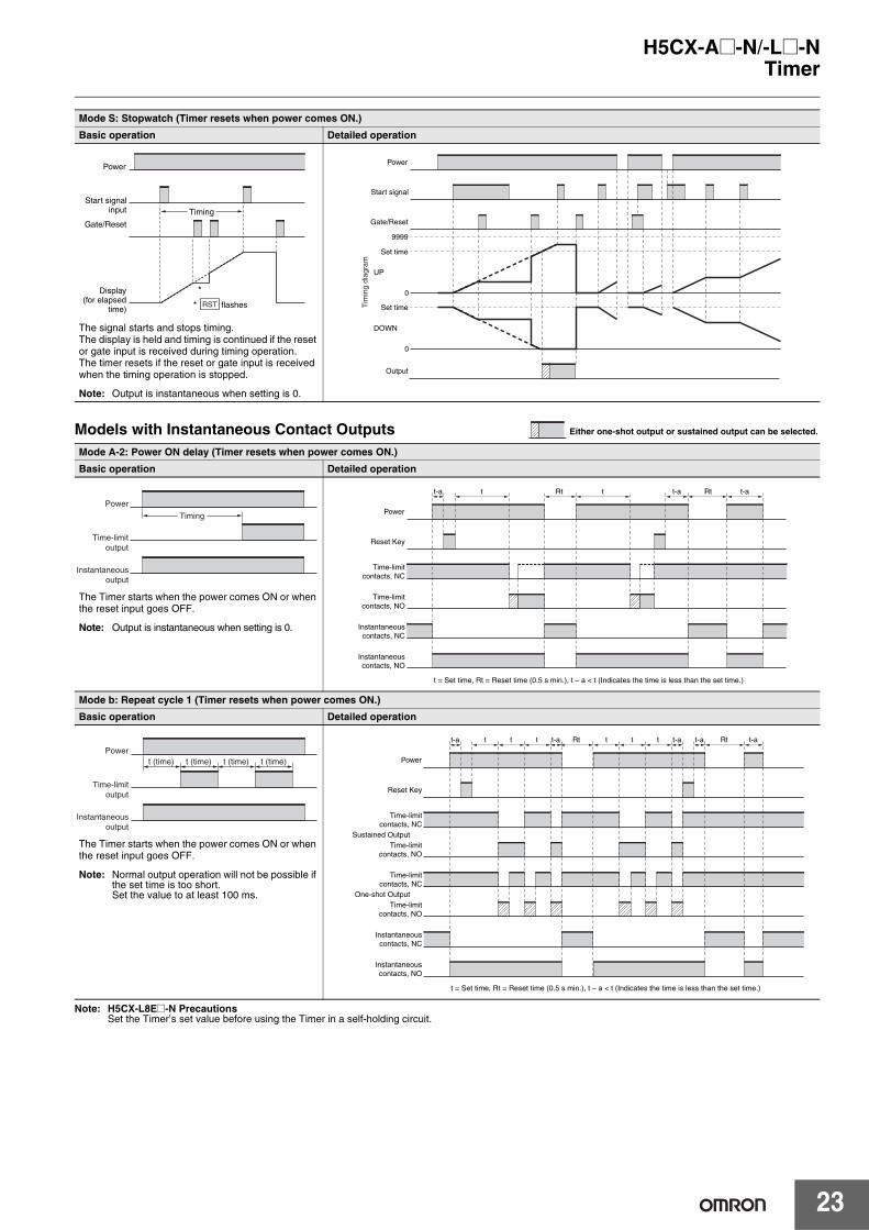
Mode S: Stopwatch (Timer resets when power comes ON.)
Basic operation Detailed operation
The signal starts and stops timing. The display is held and timing is continued if the reset or gate input is received during timing operation. The timer resets if the reset or gate input is received when the timing operation is stopped.
Note: Output is instantaneous when setting is 0.
Mode A-2: Power ON delay (Timer resets when power comes ON.)
Basic operation Detailed operation
The Timer starts when the power comes ON or when the reset input goes OFF.
Note: Output is instantaneous when setting is 0.
Mode b: Repeat cycle 1 (Timer resets when power comes ON.)
Basic operation Detailed operation
The Timer starts when the power comes ON or when the reset input goes OFF.
Note: Normal output operation will not be possible if the set time is too short.Set the value to at least 100 ms.
Power
Start signal input
Gate/Reset
Display(for elapsed
time) * flashes
*
Timing
RST
9999
Set time
0
Set time
0
UP
DOWN
Power
Start signal
Gate/Reset
Tim
ing
diag
ram
Output
Time-limit output
Power
Timing
Instantaneous output
t-a
Reset Key
Time-limit contacts, NC
Time-limit contacts, NO
Instantaneous contacts, NC
Instantaneous contacts, NO
t t-a t-aRt Rtt
t = Set time, Rt = Reset time (0.5 s min.), t – a < t (Indicates the time is less than the set time.)
Power
Instantaneous output
Time-limit output
Powert (time) t (time) t (time) t (time)
t-a t-a t-aRt Rtt t t t-a t-at t t
Reset Key
Time-limit contacts, NC
One-shot Output
Time-limit contacts, NO
Time-limit contacts, NC
Instantaneous contacts, NC
Time-limit contacts, NO
Instantaneous contacts, NO
t = Set time, Rt = Reset time (0.5 s min.), t – a < t (Indicates the time is less than the set time.)
Power
Sustained Output
H5CX-A@-N/-L@-N
24
Timer
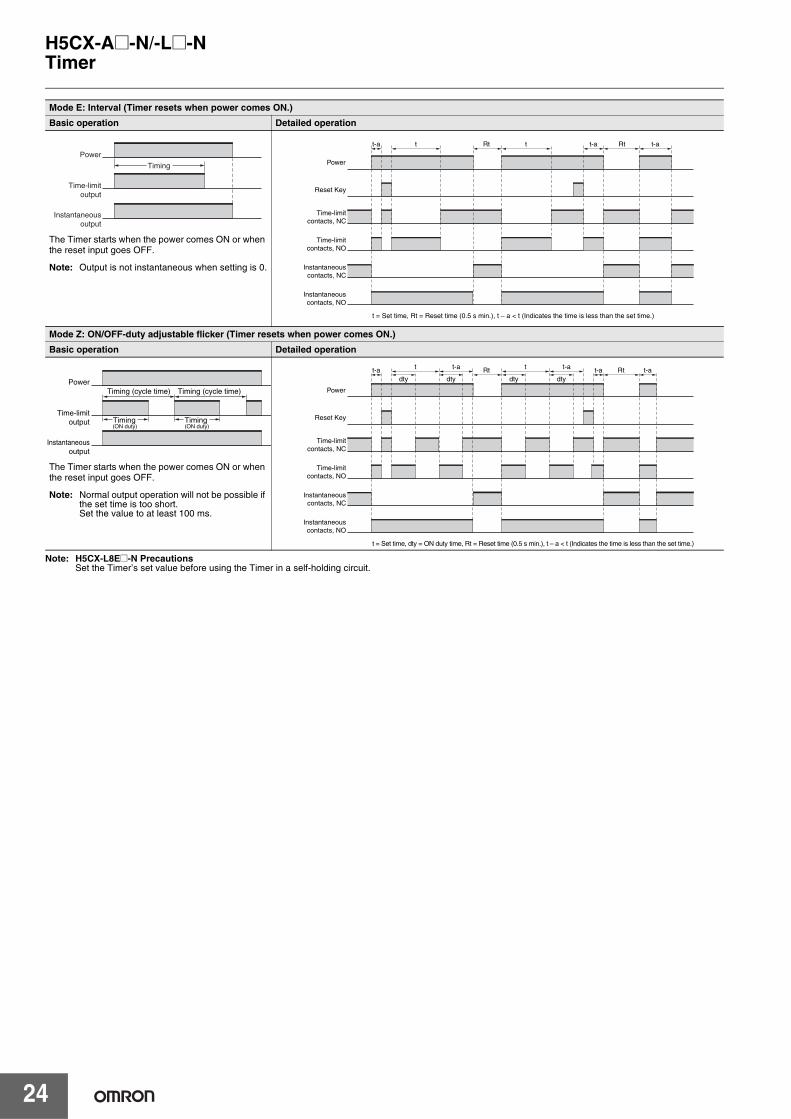
Note: H5CX-L8E@-N PrecautionsSet the Timer’s set value before using the Timer in a self-holding circuit.
Mode E: Interval (Timer resets when power comes ON.)
Basic operation Detailed operation
The Timer starts when the power comes ON or when the reset input goes OFF.
Note: Output is not instantaneous when setting is 0.
Mode Z: ON/OFF-duty adjustable flicker (Timer resets when power comes ON.)
Basic operation Detailed operation
The Timer starts when the power comes ON or when the reset input goes OFF.
Note: Normal output operation will not be possible if the set time is too short. Set the value to at least 100 ms.
Instantaneous output
Time-limit output
Power
Timing
t-a
Reset Key
Time-limit contacts, NC
Time-limit contacts, NO
Instantaneous contacts, NC
Instantaneous contacts, NO
t t-a t-aRt Rtt
t = Set time, Rt = Reset time (0.5 s min.), t – a < t (Indicates the time is less than the set time.)
Power
Timing (cycle time) Timing (cycle time)
Timing(ON duty) (ON duty)
Timing
Instantaneous output
Time-limit output
Power
t-a t-aRt Rtt tt-a t-a
dty dty dty dtyt-a
t = Set time, dty = ON duty time, Rt = Reset time (0.5 s min.), t – a < t (Indicates the time is less than the set time.)
Reset Key
Time-limit contacts, NC
Time-limit contacts, NO
Instantaneous contacts, NC
Instantaneous contacts, NO
Power
H5CX-A@-N/-L@-N
25
Twin Timer
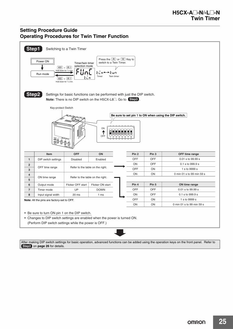
Setting Procedure GuideOperating Procedures for Twin Timer Function
After making DIP switch settings for basic operation, advanced functions can be added using the operation keys on the front panel. Refer to on page 26 for details.
Hold down for 1 s min.
Hold down for 1 s min.
Timer
Press the or Key to switch to a Twin Timer.
Twin timer
Key-protect Switch
Run mode
Power ON Timer/twin timer selection mode
1+
1+
tim
1 2 3 4 5 6 7 8OFF
ON
Step2 Settings for basic functions can be performed with just the DIP switch. Note: There is no DIP switch on the H5CX-L8@. Go to .
Step1 Switching to a Twin Timer
Disabled Enabled OFF
ON
OFF
ON
OFF
OFF
ON
ON
Refer to the table on the right.
Refer to the table on the right.
DIP switch settings
OFF time range
ON time range
Output mode
Timer mode
Input signal width
UP DOWN
Flicker OFF start Flicker ON start
20 ms 1 ms
0.01 s to 99.99 s
0.1 s to 999.9 s
1 s to 9999 s
0 min 01 s to 99 min 59 s
OFF
ON
OFF
ON
OFF
OFF
ON
ON
0.01 s to 99.99 s
0.1 s to 999.9 s
1 s to 9999 s
0 min 01 s to 99 min 59 s
Note: All the pins are factory-set to OFF.
Step3
� Be sure to turn ON pin 1 on the DIP switch.
� Changes to DIP switch settings are enabled when the power is turned ON.
(Perform DIP switch settings while the power is OFF.)
Item OFF ON OFF time rangePin 3Pin 2
ON time rangePin 5Pin 4
1
2
3
4
5
6
7
8
Be sure to set pin 1 to ON when using the DIP switch.
twn
Step3
H5CX-A@-N/-L@-N
26
Twin Timer
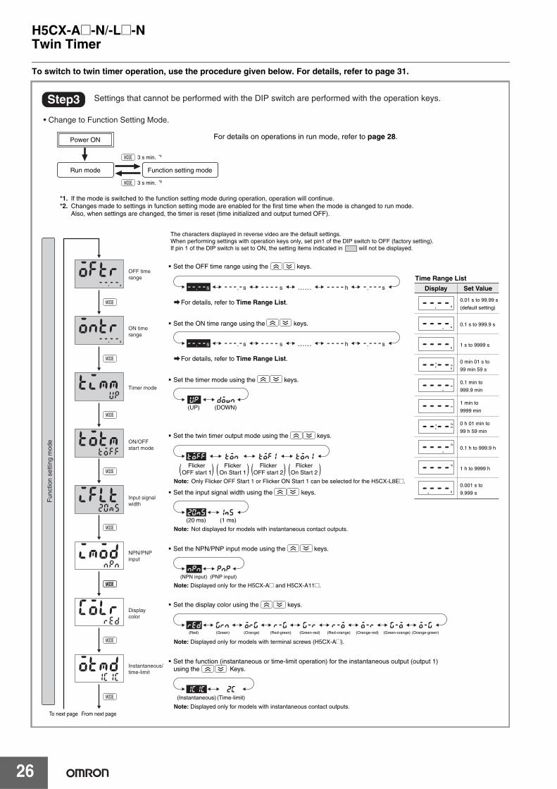
To switch to twin timer operation, use the procedure given below. For details, refer to page 31.
Run mode
Power ON
Function setting mode
From next pageTo next page
(1 ms)(20 ms)
(PNP input)(NPN input)
Note: Displayed only for the H5CX-A@ and H5CX-A11@.
(Red) (Green) (Orange) (Red-green) (Green-red) (Red-orange) (Orange-red) (Green-orange) (Orange-green)
Note: Displayed only for models with terminal screws (H5CX-A@).
Note: Displayed only for models with instantaneous contact outputs.
(Instantaneous) (Time-limit)
3 s min. *2
3 s min. *1
Step3
s s h s
s s h s
(DOWN)(UP)
OFF time range
ON time range
Timer mode
ON/OFF start mode
Input signal width
NPN/PNP input
Display color
Instantaneous/ time-limit
( ) ( ) ( ) ( )
Display Set Value
Time Range List
0.01 s to 99.99 s
(default setting)
0.1 s to 999.9 s
1 s to 9999 s
0 min 01 s to
99 min 59 s
0.1 min to
999.9 min
1 min to
9999 min
0 h 01 min to
99 h 59 min
0.1 h to 999.9 h
1 h to 9999 h
0.001 s to
9.999 s
Flicker OFF start 1
Flicker On Start 1
Flicker OFF start 2
Flicker On Start 2
Note: Not displayed for models with instantaneous contact outputs.
Note: Only Flicker OFF Start 1 or Flicker ON Start 1 can be selected for the H5CX-L8E@.
20ms
up down
1ms
pnp
grn
2c1c1c
red org r-g g-r r-o o-r g-o o-g
npn
……s
……s
toff ton tof1 ton1
For details, refer to Time Range List.
For details, refer to Time Range List.
The characters displayed in reverse video are the default settings.When performing settings with operation keys only, set pin1 of the DIP switch to OFF (factory setting).If pin 1 of the DIP switch is set to ON, the setting items indicated in will not be displayed.
Settings that cannot be performed with the DIP switch are performed with the operation keys.
• Change to Function Setting Mode.
Fun
ctio
n se
tting
mod
e
� Set the OFF time range using the keys.
� Set the ON time range using the keys.
� Set the timer mode using the keys.
� Set the twin timer output mode using the keys.
� Set the input signal width using the keys.
� Set the NPN/PNP input mode using the keys.
� Set the display color using the keys.
� Set the function (instantaneous or time-limit operation) for the instantaneous output (output 1) using the Keys.
*1. If the mode is switched to the function setting mode during operation, operation will continue.*2. Changes made to settings in function setting mode are enabled for the first time when the mode is changed to run mode. Also, when settings are changed, the timer is reset (time initialized and output turned OFF).
For details on operations in run mode, refer to page 28.
H5CX-A@-N/-L@-N
27
Twin Timer
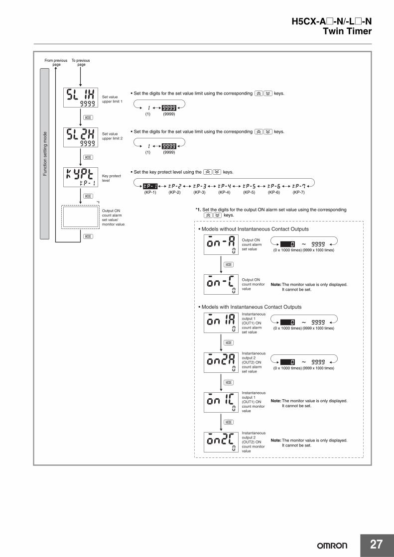
~
~
~
(KP-1) (KP-2) (KP-3) (KP-4) (KP-5) (KP-6) (KP-7)
(9999 x 1000 times)(0 x 1000 times)
(9999 x 1000 times)(0 x 1000 times)
(9999 x 1000 times)(0 x 1000 times)
Note: The monitor value is only displayed. It cannot be set.
Note: The monitor value is only displayed. It cannot be set.
Note: The monitor value is only displayed. It cannot be set.
To previous page
From previous page
Fun
ctio
n se
tting
mod
e
� Set the digits for the set value limit using the corresponding keys.
� Set the key protect level using the keys.
Set value upper limit 1
� Set the digits for the set value limit using the corresponding keys.Set value upper limit 2
Key protect level
Output ON count alarm set value/ monitor value
Output ON count alarm set value
Output ON count monitor value
Instantaneous output 1 (OUT1) ON count alarm set value
Instantaneous output 2 (OUT2) ON count alarm set value
Instantaneous output 1 (OUT1) ON count monitor value
Instantaneous output 2 (OUT2) ON count monitor value
• Models without Instantaneous Contact Outputs
• Models with Instantaneous Contact Outputs
*1. Set the digits for the output ON alarm set value using the corresponding keys.
*1
(9999)(1)
99990
99990
99990
9999
kp-2kp-1 kp-3 kp-4 kp-5 kp-6 kp-7
1
(9999)(1)99991
H5CX-A@-N/-L@-N
28
Twin Timer
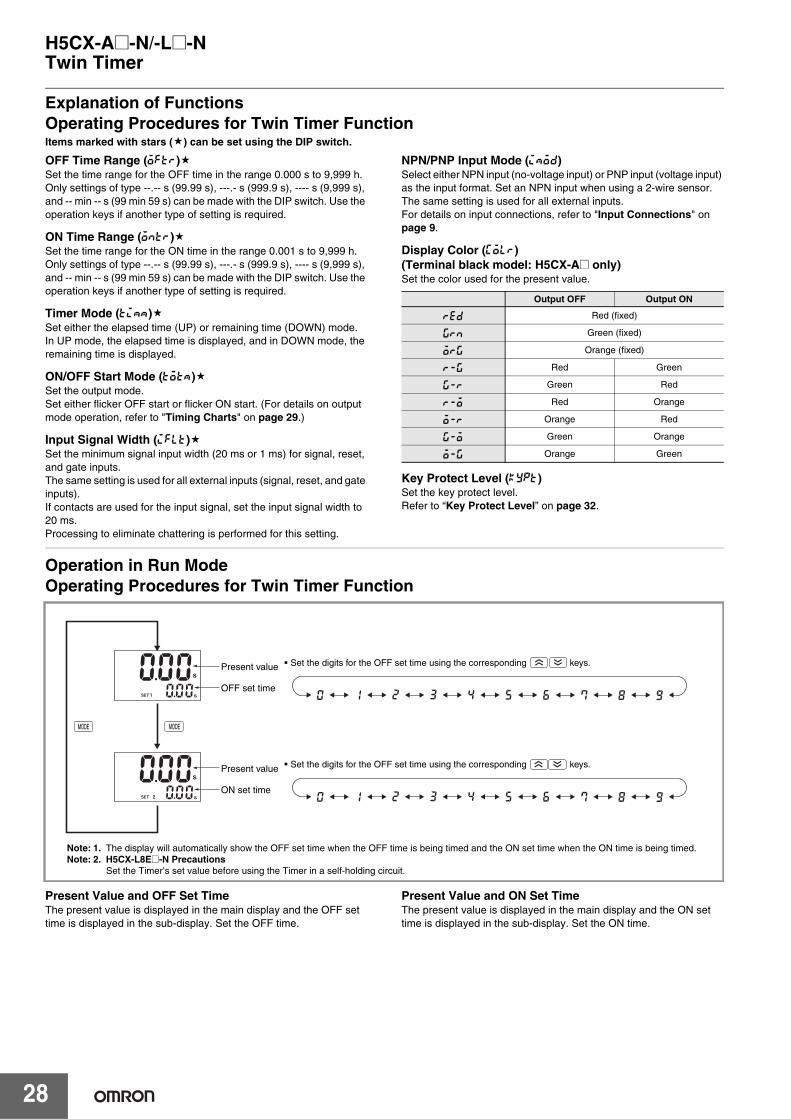
Explanation of FunctionsOperating Procedures for Twin Timer FunctionItems marked with stars ( ) can be set using the DIP switch.
OFF Time Range (oftr) Set the time range for the OFF time in the range 0.000 s to 9,999 h.Only settings of type --.-- s (99.99 s), ---.- s (999.9 s), ---- s (9,999 s), and -- min -- s (99 min 59 s) can be made with the DIP switch. Use the operation keys if another type of setting is required.
ON Time Range (ontr)Set the time range for the ON time in the range 0.001 s to 9,999 h.Only settings of type --.-- s (99.99 s), ---.- s (999.9 s), ---- s (9,999 s), and -- min -- s (99 min 59 s) can be made with the DIP switch. Use the operation keys if another type of setting is required.
Timer Mode (timm)Set either the elapsed time (UP) or remaining time (DOWN) mode.In UP mode, the elapsed time is displayed, and in DOWN mode, the remaining time is displayed.
ON/OFF Start Mode (totm) Set the output mode.Set either flicker OFF start or flicker ON start. (For details on output mode operation, refer to "Timing Charts" on page 29.)
Input Signal Width (iflt)Set the minimum signal input width (20 ms or 1 ms) for signal, reset, and gate inputs.The same setting is used for all external inputs (signal, reset, and gate inputs).If contacts are used for the input signal, set the input signal width to 20 ms. Processing to eliminate chattering is performed for this setting.
NPN/PNP Input Mode (imod) Select either NPN input (no-voltage input) or PNP input (voltage input) as the input format. Set an NPN input when using a 2-wire sensor. The same setting is used for all external inputs.For details on input connections, refer to "Input Connections" on page 9.
Display Color (colr) (Terminal black model: H5CX-A@ only)Set the color used for the present value.
Key Protect Level (kypt)Set the key protect level. Refer to “Key Protect Level” on page 32.
Operation in Run ModeOperating Procedures for Twin Timer Function
Present Value and OFF Set TimeThe present value is displayed in the main display and the OFF set time is displayed in the sub-display. Set the OFF time.
Present Value and ON Set TimeThe present value is displayed in the main display and the ON set time is displayed in the sub-display. Set the ON time.
Output OFF Output ON
red Red (fixed)
grn Green (fixed)
org Orange (fixed)
r-g Red Green
g-r Green Red
r-o Red Orange
o-r Orange Red
g-o Green Orange
o-g Orange Green
Present value
OFF set time
Present value
ON set time
Note: 1. The display will automatically show the OFF set time when the OFF time is being timed and the ON set time when the ON time is being timed.Note: 2. H5CX-L8E@-N Precautions
Set the Timer’s set value before using the Timer in a self-holding circuit.
� Set the digits for the OFF set time using the corresponding keys.
� Set the digits for the OFF set time using the corresponding keys.
H5CX-A@-N/-L@-N
29
Twin Timer
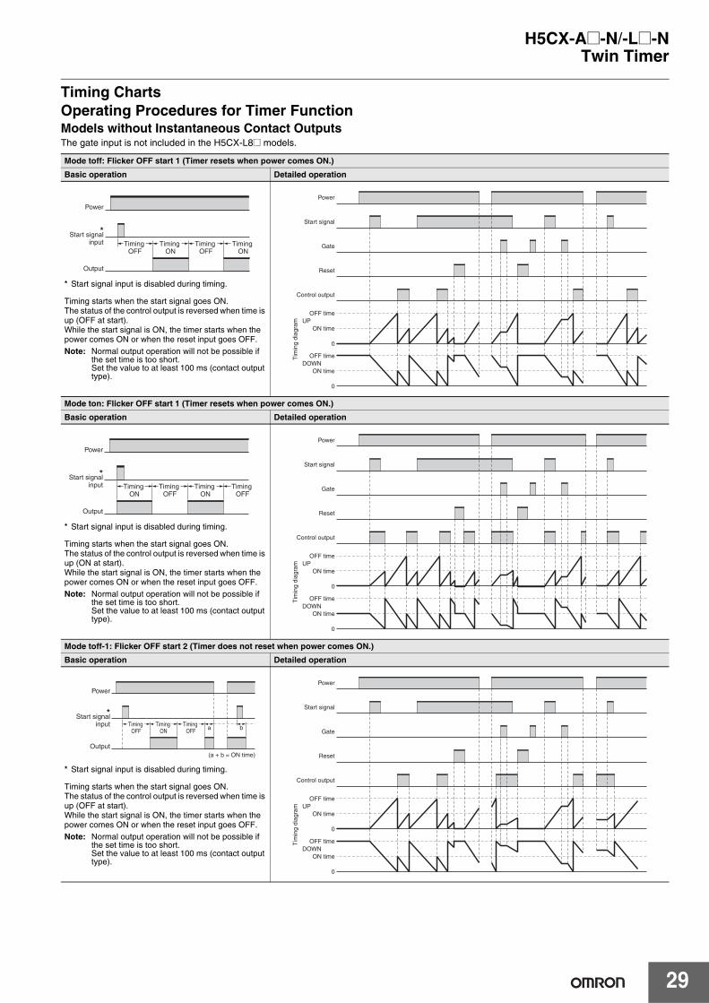
Timing ChartsOperating Procedures for Timer FunctionModels without Instantaneous Contact OutputsThe gate input is not included in the H5CX-L8@ models.
Mode toff: Flicker OFF start 1 (Timer resets when power comes ON.)
Basic operation Detailed operation
* Start signal input is disabled during timing.
Timing starts when the start signal goes ON. The status of the control output is reversed when time is up (OFF at start). While the start signal is ON, the timer starts when the power comes ON or when the reset input goes OFF. Note: Normal output operation will not be possible if
the set time is too short.Set the value to at least 100 ms (contact output type).
Mode ton: Flicker OFF start 1 (Timer resets when power comes ON.)
Basic operation Detailed operation
* Start signal input is disabled during timing.
Timing starts when the start signal goes ON. The status of the control output is reversed when time is up (ON at start). While the start signal is ON, the timer starts when the power comes ON or when the reset input goes OFF.Note: Normal output operation will not be possible if
the set time is too short. Set the value to at least 100 ms (contact output type).
Mode toff-1: Flicker OFF start 2 (Timer does not reset when power comes ON.)
Basic operation Detailed operation
* Start signal input is disabled during timing.
Timing starts when the start signal goes ON. The status of the control output is reversed when time is up (OFF at start). While the start signal is ON, the timer starts when the power comes ON or when the reset input goes OFF. Note: Normal output operation will not be possible if
the set time is too short.Set the value to at least 100 ms (contact output type).
Power
Output
*Start signal input Timing
OFFTiming
ONTiming
OFFTiming
ON
ON time
OFF time
0
OFF time
ON time
0
UP
DOWN
Power
Start signal
Gate
Reset
Control outputT
imin
g di
agra
m
Power
Output
*Start signal input Timing
ONTiming
OFFTiming
ONTiming
OFF
0
0
ON time
OFF time
OFF time
ON time
UP
DOWN
Power
Start signal
Gate
Reset
Control output
Tim
ing
diag
ram
Power
Output
*Start signal input Timing
OFFTiming
ONTiming
OFF
(a + b = ON time)
a b
0
0
ON time
OFF time
OFF time
ON time
UP
DOWN
Power
Start signal
Gate
Reset
Control output
Tim
ing
diag
ram
H5CX-A@-N/-L@-N
30
Twin Timer
Models with Instantaneous Contact Outputs
Note: H5CX-L8E@-N PrecautionsSet the Timer’s set value before using the Timer in a self-holding circuit.
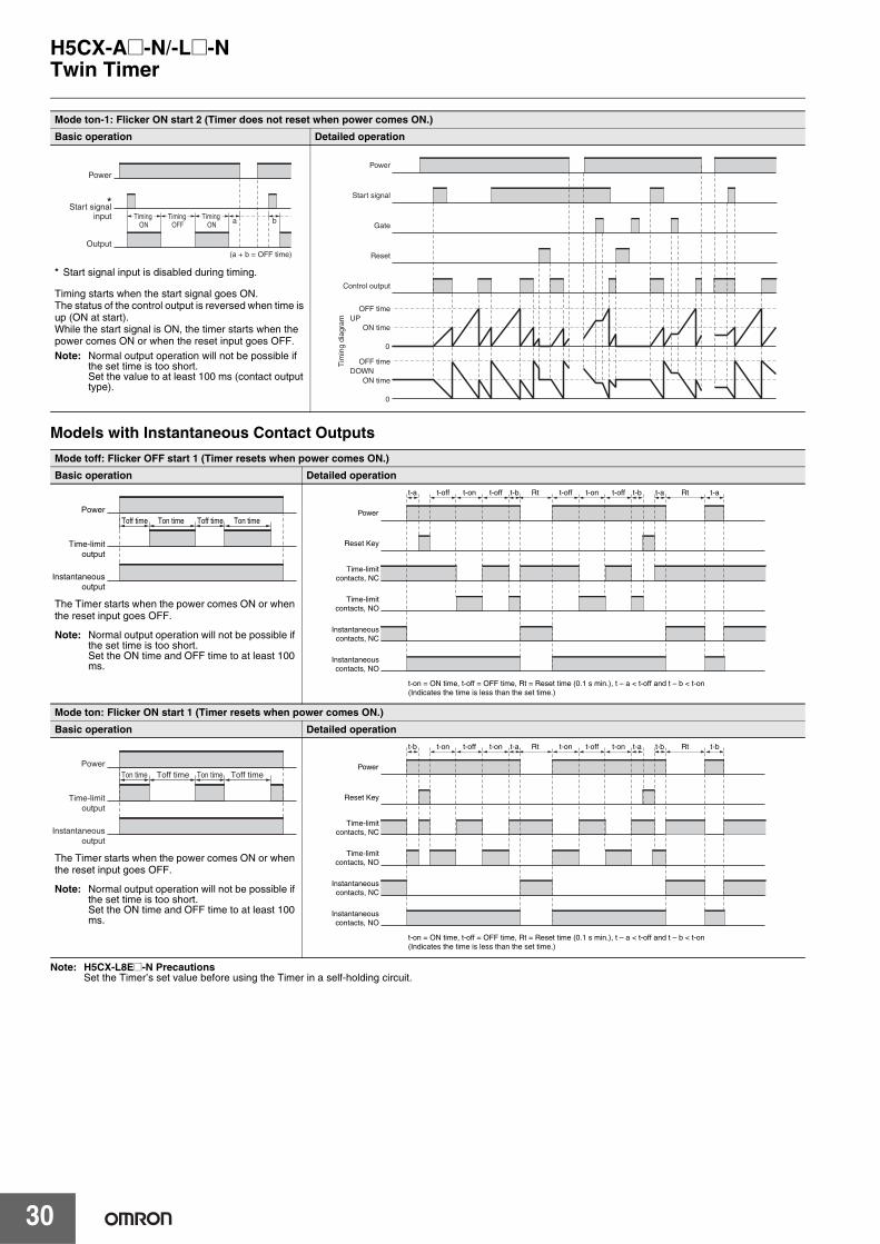
Mode ton-1: Flicker ON start 2 (Timer does not reset when power comes ON.)
Basic operation Detailed operation
* Start signal input is disabled during timing.
Timing starts when the start signal goes ON. The status of the control output is reversed when time is up (ON at start).While the start signal is ON, the timer starts when the power comes ON or when the reset input goes OFF.Note: Normal output operation will not be possible if
the set time is too short.Set the value to at least 100 ms (contact output type).
Mode toff: Flicker OFF start 1 (Timer resets when power comes ON.)
Basic operation Detailed operation
The Timer starts when the power comes ON or when the reset input goes OFF.
Note: Normal output operation will not be possible if the set time is too short. Set the ON time and OFF time to at least 100 ms.
Mode ton: Flicker ON start 1 (Timer resets when power comes ON.)
Basic operation Detailed operation
The Timer starts when the power comes ON or when the reset input goes OFF.
Note: Normal output operation will not be possible if the set time is too short.Set the ON time and OFF time to at least 100 ms.
Timing ON
Timing OFF
Timing ON
(a + b = OFF time)
a b
Power
Output
*Start signal input
0
0
ON time
OFF time
OFF time
ON time
UP
DOWN
Power
Start signal
Gate
Reset
Control output
Tim
ing
diag
ram
Ton timeToff timeTon timeToff time
Instantaneous output
Time-limit output
Power
t-a t-b t-aRt Rtt-off t-on t-off t-b t-at-off t-on t-off
t-on = ON time, t-off = OFF time, Rt = Reset time (0.1 s min.), t – a < t-off and t – b < t-on (Indicates the time is less than the set time.)
Reset Key
Time-limit contacts, NC
Time-limit contacts, NO
Instantaneous contacts, NC
Instantaneous contacts, NO
Power
Toff timeTon timeToff timeTon time
Instantaneous output
Time-limit output
Power
t-b t-a t-bRt Rtt-on t-off t-on t-a t-bt-on t-off t-on
t-on = ON time, t-off = OFF time, Rt = Reset time (0.1 s min.), t – a < t-off and t – b < t-on (Indicates the time is less than the set time.)
Reset Key
Time-limit contacts, NC
Time-limit contacts, NO
Instantaneous contacts, NC
Instantaneous contacts, NO
Power
H5CX-A@-N/-L@-N
31
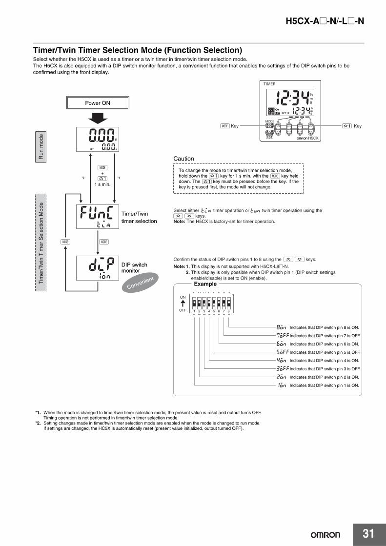
Timer/Twin Timer Selection Mode (Function Selection)Select whether the H5CX is used as a timer or a twin timer in timer/twin timer selection mode. The H5CX is also equipped with a DIP switch monitor function, a convenient function that enables the settings of the DIP switch pins to be confirmed using the front display.
1+
1
twn
11
tim
KeyKey
OFF
ON
1 2 3 4 5 6 7 8
1 s min.
Indicates that DIP switch pin 8 is ON.
Indicates that DIP switch pin 7 is OFF.
Indicates that DIP switch pin 6 is ON.
Indicates that DIP switch pin 5 is OFF.
Indicates that DIP switch pin 4 is ON.
Indicates that DIP switch pin 3 is OFF.
Indicates that DIP switch pin 2 is ON.
Indicates that DIP switch pin 1 is ON.
*1. When the mode is changed to timer/twin timer selection mode, the present value is reset and output turns OFF. Timing operation is not performed in timer/twin timer selection mode.
*2. Setting changes made in timer/twin timer selection mode are enabled when the mode is changed to run mode. If settings are changed, the HC5X is automatically reset (present value initialized, output turned OFF).
Power ON
Example
Timer/Twin timer selection
Caution
DIP switch monitor
Run
mod
eT
imer
/Tw
in T
imer
Sel
ectio
n M
ode
Convenient
*2 *1
To change the mode to timer/twin timer selection mode, hold down the key for 1 s min. with the key held down. The key must be pressed before the key. If the key is pressed first, the mode will not change.
Select either timer operation or twin timer operation using the keys.Note: The H5CX is factory-set for timer operation.
Confirm the status of DIP switch pins 1 to 8 using the keys.
Note: 1. This display is not supported with H5CX-L8@-N. 2. This display is only possible when DIP switch pin 1 (DIP switch settings
enable/disable) is set to ON (enable).
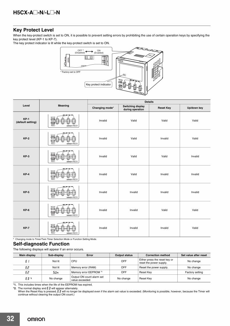
H5CX-A@-N/-L@-N
32
Key Protect LevelWhen the key-protect switch is set to ON, it is possible to prevent setting errors by prohibiting the use of certain operation keys by specifying the key protect level (KP-1 to KP-7).The key protect indicator is lit while the key-protect switch is set to ON.
* Changing mode to Timer/Twin Timer Selection Mode or Function Setting Mode.
Self-diagnostic FunctionThe following displays will appear if an error occurs.
*1. This includes times when the life of the EEPROM has expired.*2. The normal display and e3 will appear alternately.
When the Reset Key is pressed, e3 will no longer be displayed even if the alarm set value is exceeded. (Monitoring is possible, however, because the Timer will continue without clearing the output ON count.)
Level MeaningDetails
Changing mode* Switching display during operation Reset Key Up/down key
KP-1 (default setting) Invalid Valid Valid Valid
KP-2 Invalid Valid Invalid Valid
KP-3 Invalid Valid Valid Invalid
KP-4 Invalid Valid Invalid Invalid
KP-5 Invalid Invalid Invalid Invalid
KP-6 Invalid Invalid Valid Valid
KP-7 Invalid Invalid Invalid Valid
Main display Sub-display Error Output status Correction method Set value after reset
e1 Not lit CPU OFF Either press the reset key or reset the power supply. No change
e2 Not lit Memory error (RAM) OFF Reset the power supply. No change
e2 sum Memory error EEPROM *1 OFF Reset Key Factory setting
e3 *2 No change Output ON count alarm set value exceeded No change Reset Key No change
* Factory-set to OFF
*OFF(Disabled)
ON(Enabled)
Key protect indicator
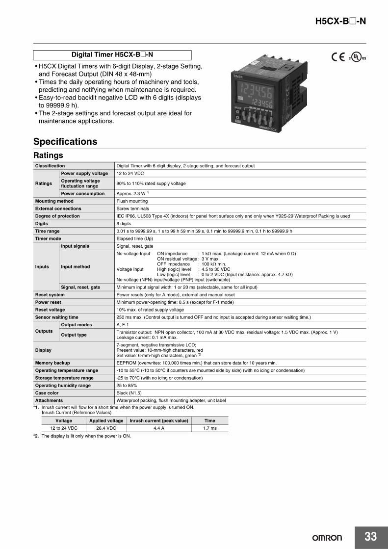
H5CX-B@-N
33
• H5CX Digital Timers with 6-digit Display, 2-stage Setting, and Forecast Output (DIN 48 x 48-mm)
• Times the daily operating hours of machinery and tools, predicting and notifying when maintenance is required.
• Easy-to-read backlit negative LCD with 6 digits (displays to 99999.9 h).
• The 2-stage settings and forecast output are ideal for maintenance applications.
SpecificationsRatings
*1. Inrush current will flow for a short time when the power supply is turned ON. Inrush Current (Reference Values)
*2. The display is lit only when the power is ON.
Digital Timer H5CX-B@-N
Classification Digital Timer with 6-digit display, 2-stage setting, and forecast output
Ratings
Power supply voltage 12 to 24 VDC
Operating voltage fluctuation range 90% to 110% rated supply voltage
Power consumption Approx. 2.3 W *1
Mounting method Flush mounting
External connections Screw terminals
Degree of protection IEC IP66, UL508 Type 4X (indoors) for panel front surface only and only when Y92S-29 Waterproof Packing is used
Digits 6 digits
Time range 0.01 s to 9999.99 s, 1 s to 99 h 59 min 59 s, 0.1 min to 99999.9 min, 0.1 h to 99999.9 h
Timer mode Elapsed time (Up)
Inputs
Input signals Signal, reset, gate
Input method
No-voltage Input ON impedance : 1 kΩ max. (Leakage current: 12 mA when 0 Ω)ON residual voltage : 3 V max.OFF impedance : 100 kΩ min.
Voltage Input High (logic) level : 4.5 to 30 VDCLow (logic) level : 0 to 2 VDC (Input resistance: approx. 4.7 kΩ)
No-voltage (NPN) input/voltage (PNP) input (switchable)
Signal, reset, gate Minimum input signal width: 1 or 20 ms (selectable, same for all input)
Reset system Power resets (only for A mode), external and manual reset
Power reset Minimum power-opening time: 0.5 s (except for F-1 mode)
Reset voltage 10% max. of rated supply voltage
Sensor waiting time 250 ms max. (Control output is turned OFF and no input is accepted during sensor waiting time.)
Outputs Output modes A, F-1
Output type Transistor output: NPN open collector, 100 mA at 30 VDC max. residual voltage: 1.5 VDC max. (Approx. 1 V)Leakage current: 0.1 mA max.
Display 7-segment, negative transmissive LCD;Present value: 10-mm-high characters, red Set value: 6-mm-high characters, green *2
Memory backup EEPROM (overwrites: 100,000 times min.) that can store data for 10 years min.
Operating temperature range -10 to 55°C (-10 to 50°C if counters are mounted side by side) (with no icing or condensation)
Storage temperature range -25 to 70°C (with no icing or condensation)
Operating humidity range 25 to 85%
Case color Black (N1.5)
Attachments Waterproof packing, flush mounting adapter, unit label
Voltage Applied voltage Inrush current (peak value) Time
12 to 24 VDC 26.4 VDC 4.4 A 1.7 ms
H5CX-B@-N
34
Characteristics
Applicable Standards
I/O Functions
Response Delay Time When Resetting (Transistor Output)The following table shows the delay from when the reset signal is input until the output is turned OFF.
(Reference value)
Accuracy of operating time and setting error (including temperature and voltage influences)
Power-ON start: ±0.01% ±50 ms max. (See note 1.)Signal start: ±0.005%±0.03 ms max. (See note 1.)Signal start for transistor output model: ±0.005%±3 ms max. (See note 1 and 2.)If the set value is within the sensor waiting time at startup the control output of the H5CX will not turn ON until the sensor waiting time passes.Note: 1. The values are based on the set value.
2. The value is applied for a minimum pulse width of 1 ms.
Insulation resistance 100 MΩmin. (at 500 VDC) between current-carrying terminal and exposed non-current-carrying metal parts
Dielectric strength 2,000 VAC, 50/60 Hz for 1 min between current-carrying metal parts and non-current-carrying metal parts 1,000 VAC, 50/60 Hz for 1 min between control output, power supply, and input circuit
Impulse withstand voltage 1.0 kV (between power terminals)1.5 kV (between current-carrying terminal and exposed non-current-carrying metal parts)
Noise immunity ±480 V (between power terminals) and ±600 V (between input terminals), square-wave noise by noise simulator (pulse width: 100 ns/1 µs, 1-ns rise)
Static immunity Destruction: 15 kVMalfunction: 8 kV
Vibration resistance
Destruction 10 to 55 Hz with 0.75-mm single amplitude in three directions for 2 h each
Malfunction 10 to 55 Hz with 0.35-mm single amplitude in three directions for 10 min each
Shock resistance
Destruction 300 m/s2 in three directions, three cycles
Malfunction 100m/s2 in three directions, three cycles
Weight Approx. 105 g (Timer only)
Approved safety standards UL508/Listing, CSA C22.2 No. 14, conforms to EN 61812-1 (pollution degree 2/overvoltage category III)Conforms to VDE0106/P100 (finger protection).
EMC
(EMI) Emission Enclosure:(EMS)Immunity ESD:
Immunity RF-interference:
Immunity Conducted Disturbance:Immunity Burst:
Immunity Surge:
EN61812-1EN55011 Group 1 class AEN61812-1EN61000-4-2: 6 kV contact discharge (level 2)
8 kV air discharge (level 3)EN61000-4-3: 10 V/m (Amplitude-modulated, 80 MHz to 1 GHz) (level 3);
10 V/m (Pulse-modulated, 900 MHz 5 MHz) (level 3)EN61000-4-6: 10 V (0.15 to 80 MHz) (level 3)EN61000-4-4: 2 kV power-line (level 3);
1 kV I/O signal-line (level 4)EN61000-4-5: 1 kV line to lines (power and output lines) (level 3);
2 kV line to ground (power and output lines) (level 3)
Inputs
Start signal Starts timing.
Reset• Resets present value. (The present value returns to 0.) • Timing stops and control output turns OFF while reset input is ON.• Reset indicator is lit while reset input is ON.
Gate Inhibits timer operation.
Outputs
Forecast value setting
Control output (OUT2) Turns ON when the present value reaches the set value.
Forecast output (OUT1) Turns ON when the present value reaches the forecast value.
Absolute value setting
Control output 2 (OUT2) Turns ON when the present value reaches set value 2.
Control output 1 (OUT1) Turns ON when the present value reaches set value 1.
Minimum reset signal width Output delay time
1 ms 0.8 to 1.2 ms
20 ms 15 to 25 ms
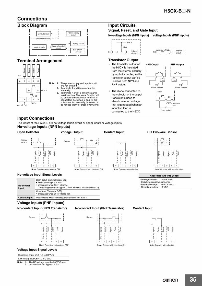
H5CX-B@-N
35
ConnectionsBlock Diagram
Terminal Arrangement
Input CircuitsSignal, Reset, and Gate Input
Transistor Output• The transistor output of
the H5CX is insulated from the internal circuitry by a photocoupler, so the transistor output can be used as both NPN and PNP output.
• The diode connected to the collector of the output transistor is used to absorb inverted voltage that is generated when an inductive load is connected to the H5CX.
Input ConnectionsThe inputs of the H5CX-B are no-voltage (short-circuit or open) inputs or voltage inputs.
No-voltage Inputs (NPN Inputs)
Voltage Inputs (PNP Inputs)
Voltage Input Signal Levels
Note: 1. The DC voltage must be 30 VDC max.2. Input resistance: Approx. 4.7 kΩ
Output circuit
Internal control circuit
Display circuit
Key switch circuit
Input circuits
Power supply circuit
(Basic insulation)
6 7 8 9 10
12 13 OUT 1
OUT 2(+)(–)
0 V
1 2 3 4 5
Res
et
Gat
e
Sig
nal
Res
et
Note: 1. The power supply and input circuit are not isolated.
2. Terminals 1 and 6 are connected internally.
3. Terminals 7 and 10 have the same reset function. The same function will be performed whichever terminal is connected. Terminals 7 and 10 are not connected internally, however, so do not use them for cross-over wiring.
Internal circuit
IN
+14 V
1 kΩ
Internal circuitIN
Approx. 4.7 kΩ
No-voltage Inputs (NPN Inputs) Voltage Inputs (PNP Inputs)
Power for load
+
Load
Power for load
+
Load
NPN Output PNP Output
Power for load
+
Timer
Inductive load
Open Collector Voltage Output Contact Input DC Two-wire Sensor
PLC or sensor
Note: Operate with transistor ON
6 7 8 9 10
Res
et
Gat
e
Sig
nal
Res
et
0 V
for
inpu
ts
Sensor
Note: Operate with transistor ON
6 7 8 9 10
Res
et
Gat
e
Sig
nal
Res
et
0 V
for
inpu
ts
Note: Operate with relay ON
6 7 8 9 10
Res
et
Gat
e
Sig
nal
Res
et
0 V
for
inpu
ts
Note: Operate with transistor ON
6 7 8 9 10
Res
et
Gat
e
Sig
nal
Res
et
0 V
for
inpu
ts
Applicable Two-wire Sensor
• Leakage current: 1.5 mA max.• Switching capacity: 5 mA min.• Residual voltage: 3.0 VDC max.• Operating voltage: 10 VDC
No-voltage Input Signal Levels
No-contact input
Short-circuit level (Transistor ON)• Residual voltage: 3 V max.• Impedance when ON: 1 kΩ max.
(The leakage current is approx. 12 mA when the impedance is 0 Ω.)
Open level (Transistor OFF)• Impedance when OFF: 100 kΩ min.
Contact input Use contacts which can adequately switch 5 mA at 10 V
No-contact Input (NPN Transistor) No-contact Input (PNP Transistor) Contact Input
High level (Input ON): 4.5 to 30 VDC
Low level (Input OFF): 0 to 2 VDC
Sensor
Note: Operate with transistor OFF
6 7 8 9 10
Res
et
Gat
e
Sig
nal
Res
et
0 V
for
inpu
ts
Sensor
Note: Operate with transistor ON
6 7 8 9 10
Res
et
Gat
e
Sig
nal
Res
et
0 V
for
inpu
ts
Note: Operate with relay ON
6 7 8 9 10
Res
et
Gat
e
Sig
nal
Res
et
0 V
for
inpu
ts
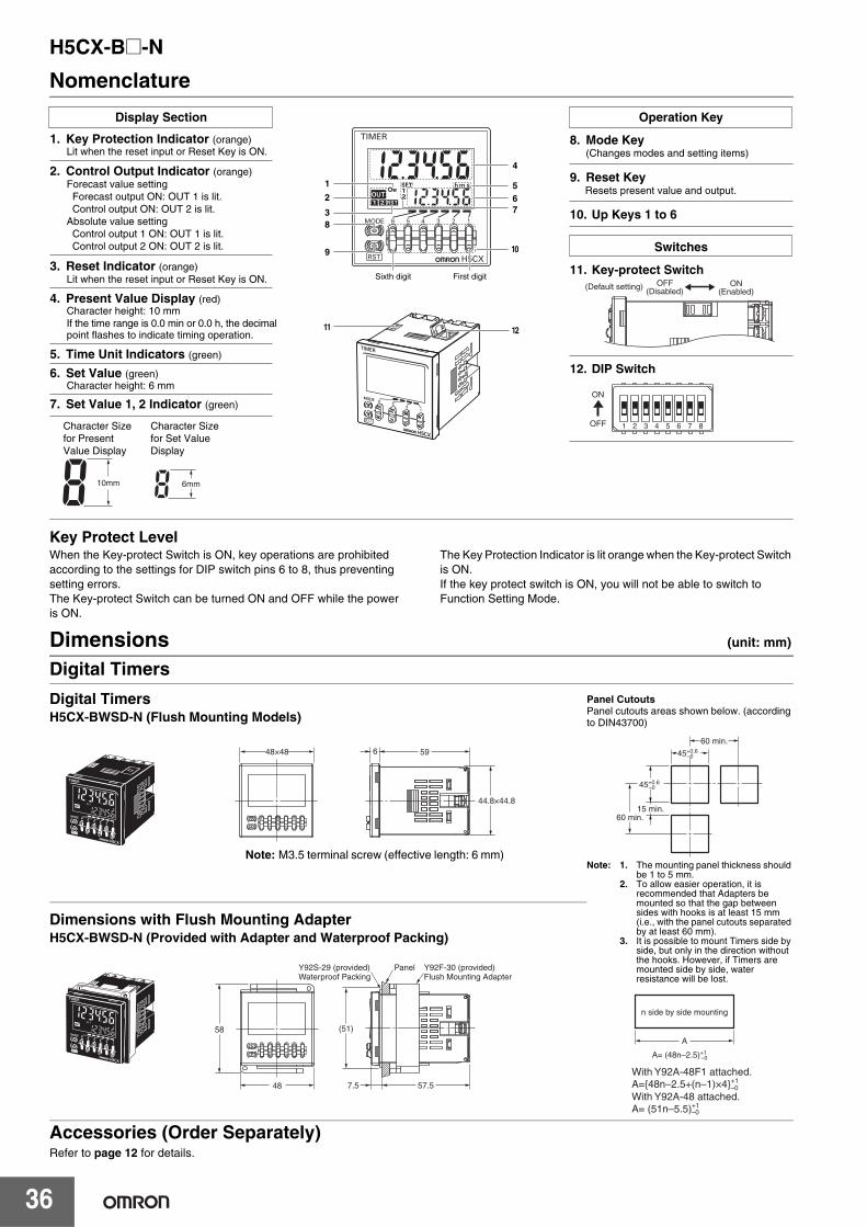
H5CX-B@-N
36
Nomenclature
Key Protect LevelWhen the Key-protect Switch is ON, key operations are prohibited according to the settings for DIP switch pins 6 to 8, thus preventing setting errors. The Key-protect Switch can be turned ON and OFF while the power is ON.
The Key Protection Indicator is lit orange when the Key-protect Switch is ON.If the key protect switch is ON, you will not be able to switch to Function Setting Mode.
Dimensions (unit: mm)
Digital Timers
Accessories (Order Separately)Refer to page 12 for details.
OFF(Disabled)
ON(Enabled)
(Default setting)
11 12
10mm 6mm
1
2
38
9
4
67
5
10
Display Section
3. Reset Indicator (orange)
1. Key Protection Indicator (orange)
2. Control Output Indicator (orange)
4. Present Value Display (red)Character height: 10 mm
7. Set Value 1, 2 Indicator (green)
If the time range is 0.0 min or 0.0 h, the decimal point flashes to indicate timing operation.
6. Set Value (green)Character height: 6 mm
5. Time Unit Indicators (green)
Lit when the reset input or Reset Key is ON.
Lit when the reset input or Reset Key is ON.
Forecast value setting
Operation Key
8. Mode Key
9. Reset Key
Switches
11. Key-protect Switch
12. DIP Switch
First digitSixth digit
Absolute value setting
(Changes modes and setting items)
Resets present value and output.
Character Size for Present Value Display
Character Size for Set Value Display
Forecast output ON: OUT 1 is lit. Control output ON: OUT 2 is lit.
Control output 1 ON: OUT 1 is lit. Control output 2 ON: OUT 2 is lit.
10. Up Keys 1 to 6
OFF
ON
1 2 3 4 5 6 7 8
Digital TimersH5CX-BWSD-N (Flush Mounting Models)
44.8×44.8
59648×48
Note: M3.5 terminal screw (effective length: 6 mm)
Panel CutoutsPanel cutouts areas shown below. (according to DIN43700)
Note: 1. The mounting panel thickness should be 1 to 5 mm.
2. To allow easier operation, it is recommended that Adapters be mounted so that the gap between sides with hooks is at least 15 mm (i.e., with the panel cutouts separated by at least 60 mm).
3. It is possible to mount Timers side by side, but only in the direction without the hooks. However, if Timers are mounted side by side, water resistance will be lost.
60 min.
60 min.
45+0.6–0
45+0.6–0
15 min.
n side by side mounting
A
A= (48n–2.5)+1 –0
With Y92A-48F1 attached.A={48n–2.5+(n–1)×4}+1 –0
With Y92A-48 attached.A= (51n–5.5)+1 –0
Dimensions with Flush Mounting AdapterH5CX-BWSD-N (Provided with Adapter and Waterproof Packing)
58
48 7.5 57.5
(51)
Y92F-30 (provided) Flush Mounting Adapter
PanelY92S-29 (provided) Waterproof Packing
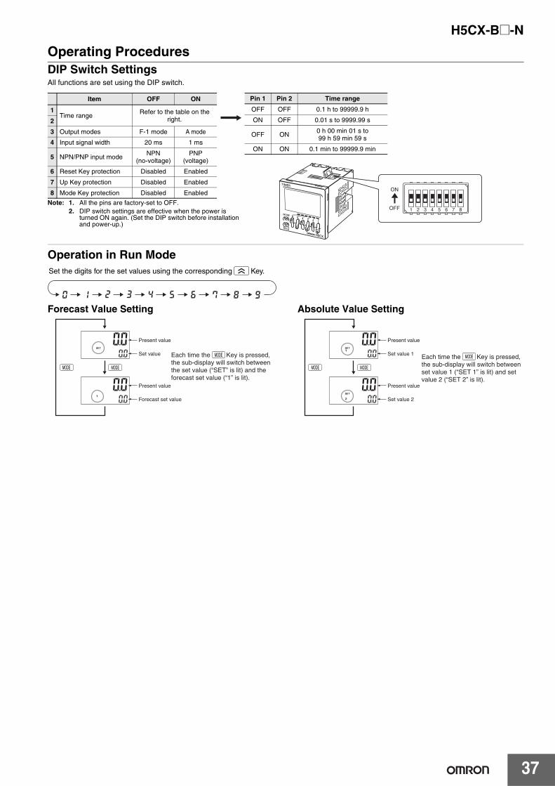
H5CX-B@-N
37
Operating ProceduresDIP Switch SettingsAll functions are set using the DIP switch.
Operation in Run Mode
Forecast Value Setting Absolute Value Setting
Note: 1. All the pins are factory-set to OFF. 2. DIP switch settings are effective when the power is
turned ON again. (Set the DIP switch before installation and power-up.)
Item OFF ON
1Time range
Refer to the table on the right.2
3 Output modes F-1 mode A mode
4 Input signal width 20 ms 1 ms
5 NPN/PNP input mode NPN
(no-voltage)PNP
(voltage)
6 Reset Key protection Disabled Enabled
7 Up Key protection Disabled Enabled
8 Mode Key protection Disabled Enabled
Pin 1 Pin 2 Time range
OFF OFF 0.1 h to 99999.9 h
ON OFF 0.01 s to 9999.99 s
OFF ON0 h 00 min 01 s to 99 h 59 min 59 s
ON ON 0.1 min to 99999.9 min
OFF
ON
1 2 3 4 5 6 7 8
Set the digits for the set values using the corresponding Key.
Set value
Present value
Forecast set value
Present value
Each time the Key is pressed, the sub-display will switch between the set value (“SET” is lit) and the forecast set value (“1” is lit).
Set value 1
Present value
Set value 2
Present value
Each time the Key is pressed, the sub-display will switch between set value 1 (“SET 1” is lit) and set value 2 (“SET 2” is lit).
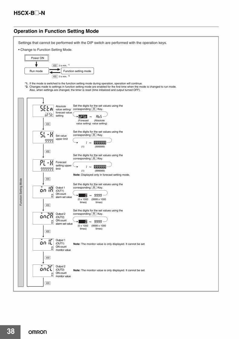
H5CX-B@-N
38
Operation in Function Setting Mode
Run mode
Power ON
Function setting mode
*1. If the mode is switched to the function setting mode during operation, operation will continue.*2. Changes made to settings in function setting mode are enabled for the first time when the mode is changed to run mode. Also, when settings are changed, the timer is reset (time initialized and output turned OFF).
3 s min. *2
3 s min. *1
Settings that cannot be performed with the DIP switch are performed with the operation keys.
• Change to Function Setting Mode.
(Absolute value setting)
(Forecast value setting)
Absolute value setting/forecast value setting
Set value upper limit
Output 1 (OUT1) ON count alarm set value
Output 2 (OUT2) ON count alarm set value
Output 1 (OUT1) ON count monitor value
Output 2 (OUT2) ON count monitor value
~
Set the digits for the set values using the corresponding Key.
(9999 x 1000 times)
(0 x 1000 times)
~
Set the digits for the set values using the corresponding Key.
Note: The monitor value is only displayed. It cannot be set.
Note: Displayed only in forecast setting mode.
~
Fun
ctio
n S
ettin
g M
ode
Set the digits for the set values using the corresponding Key.
Set the digits for the set values using the corresponding Key.
(9999 x 1000 times)
(0 x 1000 times)
Note: The monitor value is only displayed. It cannot be set.
Set the digits for the set values using the corresponding Key.
~Forecast setting upper limit
(1) (999999)
~(1) (999999)
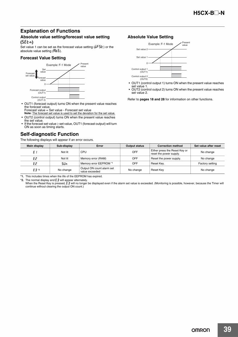
H5CX-B@-N
39
Explanation of FunctionsAbsolute value setting/forecast value setting (setm)Set value 1 can be set as the forecast value setting (ofst) or the absolute value setting (abs).
Forecast Value Setting
• OUT1 (forecast output) turns ON when the present value reaches the forecast value.Forecast value = Set value - Forecast set valueNote: The forecast set value is used to set the deviation for the set value.
• OUT2 (control output) turns ON when the present value reaches the set value.
• If the forecast set value ≥ set value, OUT1 (forecast output) will turn ON as soon as timing starts.
Absolute Value Setting
• OUT1 (control output 1) turns ON when the present value reaches set value 1.
• OUT2 (control output 2) turns ON when the present value reaches set value 2.
Refer to pages 18 and 28 for information on other functions.
Self-diagnostic FunctionThe following displays will appear if an error occurs.
*1. This includes times when the life of the EEPROM has expired.*2. The normal display and e3 will appear alternately.
When the Reset Key is pressed, e3 will no longer be displayed even if the alarm set value is exceeded. (Monitoring is possible, however, because the Timer will continue without clearing the output ON count.)
Set value
Forecast value
Forecastset value
0
Forecast output (OUT1)
Control output (OUT 2)
Present value Example: F-1 Mode
Set value 2
Set value 1
0
Control output 1 (OUT1)
Control output 2 (OUT2)
Present valueExample: F-1 Mode
Main display Sub-display Error Output status Correction method Set value after reset
e1 Not lit CPU OFF Either press the Reset Key or reset the power supply. No change
e2 Not lit Memory error (RAM) OFF Reset the power supply. No change
e2 sum Memory error EEPROM *1 OFF Reset Key. Factory setting
e3 *2 No change Output ON count alarm set value exceeded No change Reset Key No change
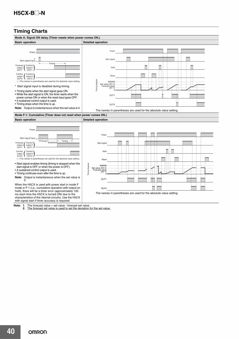
H5CX-B@-N
40
Timing Charts
Note: 1. The forecast value = set value - forecast set value2. The forecast set value is used to set the deviation for the set value.
Mode A: Signal ON delay (Timer resets when power comes ON.)
Basic operation Detailed operation
* Start signal input is disabled during timing.
• Timing starts when the start signal goes ON.• While the start signal is ON, the timer starts when the
power comes ON or when the reset input goes OFF.• A sustained control output is used.• Timing stops when the time is up. Note: Output is instantaneous when the set value is 0.
The names in parentheses are used for the absolute value setting.
Mode F-1: Cumulative (Timer does not reset when power comes ON.)
Basic operation Detailed operation
• Start signal enables timing (timing is stopped when the start signal is OFF or when the power is OFF).
• A sustained control output is used.• Timing continues even after the time is up.Note: Output is instantaneous when the set value is
0.
When the H5CX is used with power start in mode F mode or F-1 (i.e., cumulative operation with output on hold), there will be a timer error (approximately 100 ms each time the H5CX is turned ON) due to the characteristics of the internal circuitry. Use the H5CX with signal start if timer accuracy is required.
The names in parentheses are used for the absolute value setting.
Power
( ) The names in parentheses are used for the absolute value setting.
*Start signal inputTiming
Forecast output OUT1
( )Control output 1 OUT1
Control output OUT2
( )Control output 2 OUT2
Set value (SV 2)Forecast value
(SV 1)
OUT1
999999
0
OUT2
Power
Start signal
Gate
Reset
Tim
ing
diag
ram
Start signal inputTiming Timing
Sustained
Power
Forecast output OUT1
( )Control output 1 OUT1
Control output OUT2
( )Control output 2 OUT2
( ) The names in parentheses are used for the absolute value setting.
0
Set value (SV 2)Forecast value
(SV 1)
OUT1
999999
OUT2
Power
Start signal
Gate
Reset
Tim
ing
diag
ram
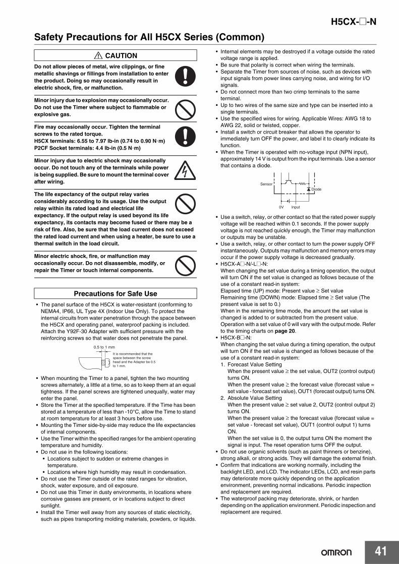
H5CX-@-N
41
Safety Precautions for All H5CX Series (Common)
Do not allow pieces of metal, wire clippings, or fine metallic shavings or fillings from installation to enter the product. Doing so may occasionally result in electric shock, fire, or malfunction.
Minor injury due to explosion may occasionally occur. Do not use the Timer where subject to flammable or explosive gas.
Fire may occasionally occur. Tighten the terminal screws to the rated torque.H5CX terminals: 6.55 to 7.97 lb-in (0.74 to 0.90 N m)P2CF Socket terminals: 4.4 lb-in (0.5 N m)
Minor injury due to electric shock may occasionally occur. Do not touch any of the terminals while power is being supplied. Be sure to mount the terminal cover after wiring.
The life expectancy of the output relay varies considerably according to its usage. Use the output relay within its rated load and electrical life expectancy. If the output relay is used beyond its life expectancy, its contacts may become fused or there may be a risk of fire. Also, be sure that the load current does not exceed the rated load current and when using a heater, be sure to use a thermal switch in the load circuit.
Minor electric shock, fire, or malfunction may occasionally occur. Do not disassemble, modify, or repair the Timer or touch internal components.
• The panel surface of the H5CX is water-resistant (conforming to NEMA4, IP66, UL Type 4X (Indoor Use Only). To protect the internal circuits from water penetration through the space between the H5CX and operating panel, waterproof packing is included. Attach the Y92F-30 Adapter with sufficient pressure with the reinforcing screws so that water does not penetrate the panel.
• When mounting the Timer to a panel, tighten the two mounting screws alternately, a little at a time, so as to keep them at an equal tightness. If the panel screws are tightened unequally, water may enter the panel.
• Store the Timer at the specified temperature. If the Time has been stored at a temperature of less than -10°C, allow the Time to stand at room temperature for at least 3 hours before use.
• Mounting the Timer side-by-side may reduce the life expectancies of internal components.
• Use the Timer within the specified ranges for the ambient operating temperature and humidity.
• Do not use in the following locations:• Locations subject to sudden or extreme changes in
temperature.• Locations where high humidity may result in condensation.
• Do not use the Timer outside of the rated ranges for vibration, shock, water exposure, and oil exposure.
• Do not use this Timer in dusty environments, in locations where corrosive gasses are present, or in locations subject to direct sunlight.
• Install the Timer well away from any sources of static electricity, such as pipes transporting molding materials, powders, or liquids.
• Internal elements may be destroyed if a voltage outside the rated voltage range is applied.
• Be sure that polarity is correct when wiring the terminals. • Separate the Timer from sources of noise, such as devices with
input signals from power lines carrying noise, and wiring for I/O signals.
• Do not connect more than two crimp terminals to the same terminal.
• Up to two wires of the same size and type can be inserted into a single terminals.
• Use the specified wires for wiring. Applicable Wires: AWG 18 to AWG 22, solid or twisted, copper.
• Install a switch or circuit breaker that allows the operator to immediately turn OFF the power, and label it to clearly indicate its function.
• When the Timer is operated with no-voltage input (NPN input), approximately 14 V is output from the input terminals. Use a sensor that contains a diode.
• Use a switch, relay, or other contact so that the rated power supply voltage will be reached within 0.1 seconds. If the power supply voltage is not reached quickly enough, the Timer may malfunction or outputs may be unstable.
• Use a switch, relay, or other contact to turn the power supply OFF instantaneously. Outputs may malfunction and memory errors may occur if the power supply voltage is decreased gradually.
• H5CX-A@-N/-L@-N:When changing the set value during a timing operation, the output will turn ON if the set value is changed as follows because of the use of a constant read-in system:Elapsed time (UP) mode: Present value ≥ Set valueRemaining time (DOWN) mode: Elapsed time ≥ Set value (The present value is set to 0.)When in the remaining time mode, the amount the set value is changed is added to or subtracted from the present value.Operation with a set value of 0 will vary with the output mode. Refer to the timing charts on page 20.
• H5CX-B@-N: When changing the set value during a timing operation, the output will turn ON if the set value is changed as follows because of the use of a constant read-in system:1. Forecast Value Setting
When the present value ≥ the set value, OUT2 (control output) turns ON.When the present value ≥ the forecast value (forecast value = set value - forecast set value), OUT1 (forecast output) turns ON.
2. Absolute Value SettingWhen the present value ≥ set value 2, OUT2 (control output 2) turns ON.When the present value ≥ the forecast value (forecast value = set value - forecast set value), OUT1 (control output 1) turns ON.When the set value is 0, the output turns ON the moment the signal is input. The reset operation turns OFF the output.
• Do not use organic solvents (such as paint thinners or benzine), strong alkali, or strong acids. They will damage the external finish.
• Confirm that indications are working normally, including the backlight LED, and LCD. The indicator LEDs, LCD, and resin parts may deteriorate more quickly depending on the application environment, preventing normal indications. Periodic inspection and replacement are required.
• The waterproof packing may deteriorate, shrink, or harden depending on the application environment. Periodic inspection and replacement are required.
CAUTION
Precautions for Safe Use
•
•
It is recommended that the space between the screw head and the Adapter be 0.5 to 1 mm.
0.5 to 1 mm
Input0V
SensorDiode
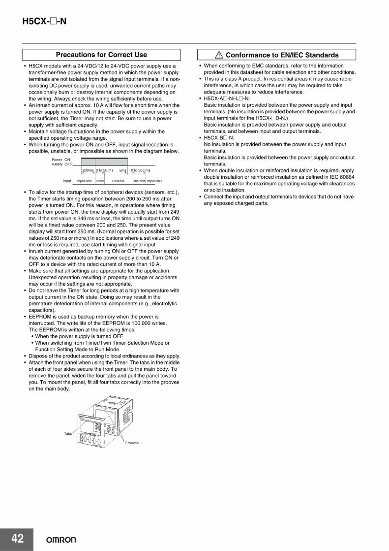
H5CX-@-N
42
• H5CX models with a 24-VDC/12 to 24-VDC power supply use a transformer-free power supply method in which the power supply terminals are not isolated from the signal input terminals. If a non-isolating DC power supply is used, unwanted current paths may occasionally burn or destroy internal components depending on the wiring. Always check the wiring sufficiently before use.
• An inrush current of approx. 10 A will flow for a short time when the power supply is turned ON. If the capacity of the power supply is not sufficient, the Timer may not start. Be sure to use a power supply with sufficient capacity.
• Maintain voltage fluctuations in the power supply within the specified operating voltage range.
• When turning the power ON and OFF, input signal reception is possible, unstable, or impossible as shown in the diagram below.
• To allow for the startup time of peripheral devices (sensors, etc.), the Timer starts timing operation between 200 to 250 ms after power is turned ON. For this reason, in operations where timing starts from power ON, the time display will actually start from 249 ms. If the set value is 249 ms or less, the time until output turns ON will be a fixed value between 200 and 250. The present value display will start from 250 ms. (Normal operation is possible for set values of 250 ms or more.) In applications where a set value of 249 ms or less is required, use start timing with signal input.
• Inrush current generated by turning ON or OFF the power supply may deteriorate contacts on the power supply circuit. Turn ON or OFF to a device with the rated current of more than 10 A.
• Make sure that all settings are appropriate for the application. Unexpected operation resulting in property damage or accidents may occur if the settings are not appropriate.
• Do not leave the Timer for long periods at a high temperature with output current in the ON state. Doing so may result in the premature deterioration of internal components (e.g., electrolytic capacitors).
• EEPROM is used as backup memory when the power is interrupted. The write life of the EEPROM is 100,000 writes. The EEPROM is written at the following times:• When the power supply is turned OFF• When switching from Timer/Twin Timer Selection Mode or
Function Setting Mode to Run Mode• Dispose of the product according to local ordinances as they apply.• Attach the front panel when using the Timer. The tabs in the middle
of each of four sides secure the front panel to the main body. To remove the panel, widen the four tabs and pull the panel toward you. To mount the panel, fit all four tabs correctly into the grooves on the main body.
• When conforming to EMC standards, refer to the information provided in this datasheet for cable selection and other conditions.
• This is a class A product. In residential areas it may cause radio interference, in which case the user may be required to take adequate measures to reduce interference.
• H5CX-A@-N/-L@-N:Basic insulation is provided between the power supply and input terminals. (No insulation is provided between the power supply and input terminals for the H5CX-@D-N.)Basic insulation is provided between power supply and output terminals, and between input and output terminals.
• H5CX-B@-N:No insulation is provided between the power supply and input terminals.Basic insulation is provided between the power supply and output terminals.
• When double insulation or reinforced insulation is required, apply double insulation or reinforced insulation as defined in IEC 60664 that is suitable for the maximum operating voltage with clearances or solid insulation.
• Connect the input and output terminals to devices that do not have any exposed charged parts.
Precautions for Correct Use
Input Impossible
200ms 5ms0 to 50 ms 0 to 500 ms
PossibleUnstable Unstable Impossible
Power supply
ONOFF
Tabs
Grooves
Conformance to EN/IEC Standards
Warranty and Application ConsiderationsRead and Understand This Catalog
Please read and understand this catalog before purchasing the products. Please consult your OMRON representative if you have any questions or comments.
Warranty and Limitations of Liability
WARRANTYOMRON's exclusive warranty is that the products are free from defects in materials and workmanship for a period of one year (or other period if specified) from date of sale by OMRON.OMRON MAKES NO WARRANTY OR REPRESENTATION, EXPRESS OR IMPLIED, REGARDING NON-INFRINGEMENT, MERCHANTABILITY, OR FITNESS FOR PARTICULAR PURPOSE OF THE PRODUCTS. ANY BUYER OR USER ACKNOWLEDGES THAT THE BUYER OR USER ALONE HAS DETERMINED THAT THE PRODUCTS WILL SUITABLY MEET THE REQUIREMENTS OF THEIR INTENDED USE. OMRON DISCLAIMS ALL OTHER WARRANTIES, EXPRESS OR IMPLIED.
LIMITATIONS OF LIABILITYOMRON SHALL NOT BE RESPONSIBLE FOR SPECIAL, INDIRECT, OR CONSEQUENTIAL DAMAGES, LOSS OF PROFITS, OR COMMERCIAL LOSS IN ANY WAY CONNECTED WITH THE PRODUCTS, WHETHER SUCH CLAIM IS BASED ON CONTRACT, WARRANTY, NEGLIGENCE, OR STRICT LIABILITY.In no event shall the responsibility of OMRON for any act exceed the individual price of the product on which liability is asserted.IN NO EVENT SHALL OMRON BE RESPONSIBLE FOR WARRANTY, REPAIR, OR OTHER CLAIMS REGARDING THE PRODUCTS UNLESS OMRON'S ANALYSIS CONFIRMS THAT THE PRODUCTS WERE PROPERLY HANDLED, STORED, INSTALLED, AND MAINTAINED AND NOT SUBJECT TO CONTAMINATION, ABUSE, MISUSE, OR INAPPROPRIATE MODIFICATION OR REPAIR.
Application Considerations
SUITABILITY FOR USEOMRON shall not be responsible for conformity with any standards, codes, or regulations that apply to the combination of products in the customer's application or use of the products.Take all necessary steps to determine the suitability of the product for the systems, machines, and equipment with which it will be used.Know and observe all prohibitions of use applicable to this product.NEVER USE THE PRODUCTS FOR AN APPLICATION INVOLVING SERIOUS RISK TO LIFE OR PROPERTY WITHOUT ENSURING THAT THE SYSTEM AS A WHOLE HAS BEEN DESIGNED TO ADDRESS THE RISKS, AND THAT THE OMRON PRODUCTS ARE PROPERLY RATED AND INSTALLED FOR THE INTENDED USE WITHIN THE OVERALL EQUIPMENT OR SYSTEM.
Disclaimers
PERFORMANCE DATAPerformance data given in this catalog is provided as a guide for the user in determining suitability and does not constitute a warranty. It may represent the result of OMRON's test conditions, and the users must correlate it to actual application requirements. Actual performance is subject to the OMRON Warranty and Limitations of Liability.
CHANGE IN SPECIFICATIONSProduct specifications and accessories may be changed at any time based on improvements and other reasons. Consult with your OMRON representative at any time to confirm actual specifications of purchased product.
DIMENSIONS AND WEIGHTSDimensions and weights are nominal and are not to be used for manufacturing purposes, even when tolerances are shown.
ALL DIMENSIONS SHOWN ARE IN MILLIMETERS.To convert millimeters into inches, multiply by 0.03937. To convert grams into ounces, multiply by 0.03527.

Authorized Distributor:
In the interest of product improvement, specifications are subject to change without notice.
Cat. No. L111-E1-01OMRON Industrial Automation Global: www.ia.omron.comPrinted in Japan
0709
OMRON CorporationIndustrial Automation Company
Regional HeadquartersOMRON EUROPE B.V.Wegalaan 67-69-2132 JD HoofddorpThe NetherlandsTel: (31)2356-81-300/Fax: (31)2356-81-388
OMRON ELECTRONICS LLCOne Commerce Drive Schaumburg,IL 60173-5302 U.S.A.Tel: (1) 847-843-7900/Fax: (1) 847-843-7787
OMRON ASIA PACIFIC PTE. LTD.No. 438A Alexandra Road # 05-05/08 (Lobby 2), Alexandra Technopark, Singapore 119967Tel: (65) 6835-3011/Fax: (65) 6835-2711
OMRON (CHINA) CO., LTD.Room 2211, Bank of China Tower, 200 Yin Cheng Zhong Road, PuDong New Area, Shanghai, 200120, ChinaTel: (86) 21-5037-2222/Fax: (86) 21-5037-2200
Control Devices Division H.Q.Industrial Component Division2-2-1 Nishikusatsu, Kusatsu-shi, Shiga, 525-0035 JapanTel: (81) 77-565-5160/Fax: (81) 77-565-5569
© OMRON Corporation 2009 All Rights Reserved.