Embed Size (px)
Citation preview

MESTA ELECTRONICS, INC.
Digital Power Manager 50 amp Panel Owner’s Manual
11020 Parker Drive N. Huntingdon, PA 15642 412/754-3000
SAVE THESE IMPORTANT SAFETY INSTRUCTIONS

i
Table of Contents 1. INTRODUCTION .................................................................................................................................. 1
1.1 THEORY OF OPERATION ............................................................................................................ 1 2. SAFETY PRECAUTIONS ..................................................................................................................... 2 3. INSTALLATION .................................................................................................................................... 3
3.1 PLACING THE DIGITAL POWER MANAGER .............................................................................. 3 3.2 CONNECTING POWER WIRING AND EXTERNAL CURRENT SENSORS ................................ 4
3.2.1 INSTALLATION PROCEDURE .............................................................................................. 5 3.2.2 CUSTOMER RELAY CONTACTS ......................................................................................... 5
4. OPERATING THE UNIT ....................................................................................................................... 6 4.1 TURNING ON THE UNIT ............................................................................................................... 6 4.2 FRONT PANEL TOUCH SCREEN DISPLAY ................................................................................ 7 4.3 STATUS CONNECTIONS ............................................................................................................. 9 4.4 PREVENTATIVE MAINTENANCE ................................................................................................. 9
5. SERIAL/ETHERNET COMMUNICATIONS ........................................................................................ 10 5.1 CONNECTING TO THE SERIAL COMMUNICATIONS INTERFACE ......................................... 10 5.2 CONNECTING TO THE ETHERNET INTERFACE ..................................................................... 11 5.3 SYSTEM SOFTWARE COMMANDS ........................................................................................... 12
5.3.1 STATUS REPORTS ............................................................................................................. 12 5.3.2 DPM DATE AND TIME ......................................................................................................... 13 5.3.3 HISTORICAL EVENT DATABASE DISPLAY INFORMATION ............................................ 14 5.3.4 CHANGING SYSTEM OPERATING PARAMETERS .......................................................... 14
APPENDIX A. DPM SPECIFICATIONS BY MODEL .............................................................................. 17 APPENDIX B. CUSTOMER INSTALLATION DIAGRAM ....................................................................... 19 APPENDIX C. WARRANTY/SERVICE AND REPAIR ............................................................................ 21
List of Illustrations Figure 1: Enclosure Installation Clearances ............................................................................................. 3 Figure 2: Installation Block Diagram ......................................................................................................... 4
List of Tables Table 1: Ratings for required branch circuit protection ............................................................................. 4 Table 2: Ratings for required branch circuit protection ............................................................................. 4 Table 3: RS232 Pin Configuration .......................................................................................................... 10 Table 4: Serial Communications Protocol ............................................................................................... 10 Table 5: Status Display Parameters ....................................................................................................... 13

3ACDPM050 - 3ACDPM300
ii
(Page Intentionally Left Blank)

1
1. INTRODUCTION
Electronic equipment and controls, such as computers, computer peripherals, AC and DC motor drives and many other critical and commonly used electronic hardware in the market place today, immensely overburden the electric utilities with various harmonic distortions. Such equipment, or nonlinear loads, uniquely characterized with high current crest factor (C.F.) and low power factor (P.F.) create a harmonic distortion in the plant utility grid. These distortions make the operation of communications and other sensitive equipment nearly impossible. Electric utilities are using more sophisticated metering equipment to monitor power factor so that distortion power factor is now measured in addition to the traditional displacement power factor. This can result in substantial penalty charges on a plant's electric bill. Power consultants, computer and communications specialists are therefore compelled to include in their specifications compliance to ANSI/IEEE 519-1992 stringent requirements, which define the maximum amount of harmonic distortion that newly installed equipment and controls are allowed to inject in the utility lines.
Many approaches have been devised in the past, aimed to minimize the harmonic distortion. Special zigzag transformers, phase shift transformers, and passive filters have all brought some type of harmonic relief, but not without severe limitations. Since the generated harmonics are a function of the actual load, and can vary during the course of the operation, it is impossible to design such a filter in advance, which will cover any and all loads and harmonics conditions.
Unlike the harmonic correction methods listed above, the Mesta Digital Power Factor and Harmonic Manager (Mesta DPM) is a true active filter. Its design does not necessitate knowledge regarding the harmonic profile of the load. Only the Total Current Distortion and phase displacement are required in sizing the DPM to any existing non-linear load.
1.1 THEORY OF OPERATION
The Mesta DPM coexists with the utility voltage, remaining phase-locked and voltage-equalized. The four quadrant Mesta inverter, the heart of the Mesta DPM, operates at a modulation frequency of several thousand cycles per second, which allows the DPM to respond to the exact need as it develops. The inverter draws energy from the utility at some portions of the cycle, stores the energy, then delivers that energy to the load later in the cycle when it is needed. The powerful microcontroller, while it is continuously investigating the load harmonics, instantaneously directs the energy/current flow in and out of the inverter, thus, improving the line current harmonic content and power factor.
WARNING
Always keep the front door fastened. Leaving the unit’s door open may expose personnel to an electrical shock hazard that could result in death or injury, or damage to the DPM or to the electrical loads it is correcting.

2
2. SAFETY PRECAUTIONS
Always keep the door closed and locking screws in the locked position. This equipment should be installed, operated and maintained only by qualified personnel. The only time that the unit should be opened is for initial installation or routine maintenance. The following warnings apply to the equipment and should be read and fully understood by qualified personnel before they begin working on the unit:
WARNING
Risk of Electric Shock exists inside the Digital Power Manager (DPM) enclosure. The AC Disconnect should be in the OFF position for 5 minutes prior to opening the door of the unit. For additional safety, if possible, the external AC breaker feeding the DPM and the non-linear load should also be locked in the OFF position. If this is not possible, the top terminals of the disconnect inside the unit will be electrically hot, and must therefore be avoided. Even with the disconnect turned off, hazardous voltages may exist within the unit for several minutes after the disconnect is turned off. THESE HAZARDOUS VOLTAGES REPRESENT A POSSIBLE SHOCK HAZARD THAT COULD RESULT IN DEATH OR INJURY TO PERSONNEL.
WARNING
The Digital Power Manager (DPM) contains capacitive components that remain energized for several minutes after power to the DPM has been removed. The AC disconnect should be in the OFF position for 5 minutes prior to opening the door of the unit. Of particular interest are the large can capacitors mounted in front of the heat sink. Two red lights mounted on the High Voltage Interface PC Board indicate if these capacitors are charged to hazardous levels. If either of these two red lights is lit, potentially deadly voltage exists on these capacitors. While these capacitors are charged, hazardous voltage exists in several places within the unit (including, but not limited to all DC filter capacitors; bussbars associated with the capacitors; the components on the heatsink; several other components located on the back panel; and the High Voltage Interface PC Board). The capacitors have circuits to discharge them. Do not proceed into the unit until the capacitors have been sufficiently discharged, signified by both red lights being off. Once the red lights are off, carefully measure the voltage across a far left and a far right large DC buss capacitor using a DC voltmeter, making sure you do not come in contact with any other metal objects within the cabinet. Make certain that both voltages you have measured are below 10 vdc before proceeding within the cabinet.
WARNING
Do not rely entirely on the red lights for safety. A failure in the lights or circuits that drive the lights could result in no lights being lit when a hazardous voltage exists. However, never proceed into the unit if the lights are on. Always use a DC voltmeter to measure the actual capacitor voltage once the lights are dim or off. Do not come in contact with any metal objects that are not grounded to the frame while making this measurement.
WARNING
The AC Disconnect MUST remain in the OFF position at all times while the door to the system is open. Turning the AC Disconnect on after the door has been opened will result in hazardous voltages being present at many locations within the unit. SUCH HAZARDOUS VOLTAGES COULD CAUSE ELECTRIC SHOCK THAT COULD RESULT IN DEATH OR INJURY.

3
3. INSTALLATION
This equipment should only be installed, operated and maintained by qualified personnel that have been trained to work with potentially hazardous electrical equipment.
Before the Digital Power Manager can be operated properly, the unit must be mounted to a sturdy wall (wall mounted), or placed on a level surface (free standing) with the power and signal wiring properly connected. It is highly recommended that before any wiring is done, the installer consults the Local and National wiring codes to determine the adequate AWG of the wire and suitable conduit to house the external wiring. In order to perform any of the following wiring functions, the AC disconnect in the unit must be in the off position as well as the distribution box breaker that connects the DPM to the utility and load. In addition, all of the safety instructions and warnings located in the “Safety Precautions” section of this manual should be read before proceeding.
3.1 PLACING THE DIGITAL POWER MANAGER
The Digital Power Manager is designed to be either wall mounted or free standing, depending on the current rating of the system. Open Panel models can be mounted inside a suitable industrial enclosure. The wall-mounted enclosures have holes located on the back of the enclosure for bolting the unit to a wall. The wall-mounted units should be mounted so that there is a gap of at least one foot between the bottom of the enclosure and the floor. This distance is necessary to insure sufficient airflow into the box from the bottom. A minimum of 9 inches of clearance is necessary between the top of the enclosure and any significant obstructions to allow adequate airflow out of the top of the box. The box should be positioned so that AC, chassis ground, and control wires can readily enter the top of the box on the right and left sides, indicated in the wiring instructions that follow. A minimum of 3 feet of clearance in front of the unit is necessary to allow opening the door sufficiently to service the unit. A minimum of 1 inch of clearance is required on the left and right sides of the cabinet. The diagram to the right reviews all of these clearance specifications graphically. The DPM is designed to operate in a 0ºC – 40ºC ambient temperature.
Important Note: Industrial enclosures that are used to house open panel models must be equipped with input air filter(s) and exhaust fan(s) to provide adequate air flow for the system. Please refer to the air flow (CFM) and heat loss specifications in appendix A of this manual. Consult factory if additional information is required.
The DPM may be placed in an industrial environment that is protected from water, metal filings or other conductive impurities and corrosive chemicals. The area should not be subjected to an overwhelming amount of dust or dirt; otherwise, frequent cleaning of the system and replacement of the input air filter will be required. Refer to specifications (appendix A) for filter size and type.
Figure 1: Enclosure Installation Clearances
DPM
9"Min.
1 FtMin.
1" Min.1" Min.

4
3.2 CONNECTING POWER WIRING AND EXTERNAL CURRENT SENSORS
Before beginning to install the system, confirm that the voltage rating and system type (Delta) of the DPM is the same as the load. Once this is confirmed, a suitable interface must be found in the load circuit to connect the DPM. This interface must be able to accommodate the power wiring to the DPM, the wiring to the non-linear load, the wiring from the utility, and the DPM current sensors. The figure to the right shows all the components just mentioned and illustrates the connections between them.
For detailed installation drawings, refer to the customer installation diagram for your particular model in appendix B of this manual.
The customer/installer is responsible for providing suitable (UL listed fuses or equivalent) branch circuit protection for the power wiring leading to the DPM. The current rating of this branch circuit protection is specified in the table below.
Table 1: Ratings for required branch circuit protection
Mesta DPM Model Min. Current Rating for Branch Circuit Protection
3ACDPM50-480-1 (or O) 63 amps
3ACDPM100-480-1 (or O) 125 amps
3ACDPM150-480-1 (or O 200 amps
3ACDPM200-480-1 (or O) 250 amps
3ACDPM300-480-1 (or O) 400 amps
The size (awg) of the power wiring leading to the Mesta DPM should be selected in accordance with the current rating of the branch circuit protection indicated above, subject to any and all applicable national and local electric codes. Any power or ground wire selected that is larger than 3 awg should be derated, according to National Electric Code, to allow for the high frequency (400Hz) current produced by the DPM.
Once the interface location, proper branch circuit protection and the appropriate power wiring have been selected the DPM should be prepared for installation. On the right side on the top of the DPM cabinet there is a pilot hole (two pilot holes for 200/300 amp systems), which is provided for the power wiring. The pilot hole on the left side on the top of the system is provided for the CT wiring and the wiring for the customer relay contacts. A qualified technician should use a punch to enlarge the pilot holes on the cabinet for the appropriate type of conduit to be used. Drilling or filing should be avoided, as any metal particles that fall inside the unit could interfere with the operation of the electrical/electronic components of the system.
Table 2: Field Wiring Terminal Ratings (Copper Wire Only, 75°C wire or equivalent)
Mesta DPM Model Maximum Permissible Wire Range (awg) Terminal Torque (lbs.-in.)
3ACDPM50-480-1 (or O) 2/ 1/0 27
3ACDPM100-480-1 (or O) 3/0 125
3ACDPM150-480-1 (or O) 3/0 125
3ACDPM200-480-1 (or O) 350 MCM 140
3ACDPM300-480-1 (or O) Terminal Tabs accept 3/8” SAE grade 5 (M10) bolts 300
Figure 2: Installation Block Diagram

5
3.2.1 INSTALLATION PROCEDURE
To install a Mesta DPM with CTs (current transformers) monitoring the “line” side of the DPM, perform the following recommended procedure. Do not attempt to turn on power to the DPM until all steps have been completed. The line side is defined as the wiring from the utility that powers both the DPM and the loads to be corrected. Conversely, the load side is defined as the wiring “after” the DPM that powers only the loads to be corrected. The CTs should be rated for the maximum anticipated load current of the conductor on which they will be installed. The I.D. of the CTs should be larger than the O.D. of the conductors. For detailed installation drawings, refer to the customer installation diagram for your particular model in appendix B of this manual. Note: The Mesta DPM may not operate properly if power factor correction capacitors are connected on the load side of the CTs. CTs must be installed on the load side of these capacitors for proper operation. Consult factory for any questions regarding the presence of power factor correction capacitors.
1) It is highly recommended for safety reasons to turn off power feeding the circuit that powers the DPM and loads to be corrected prior to proceeding.
2) Designate the 3 phases of your power circuit as phases A, B, and C. Phase rotation is not a concern, so the designation you make is arbitrary. If power is off and kept off until all of the remaining steps are completed, the remaining steps may be performed in any order; otherwise step 3 must precede step 4.
3) Terminate the secondary leads of CT A to A+ and A- terminals, CT B to B+ and B- terminals, and CT C (Optional) to C+ and C- of P1 of the CT Interface board inside the DPM enclosure. If using CTs supplied by Mesta, the black lead is the “+” lead and the white lead is the “-“ lead. Use a tightening torque of 4 in. lb. Also, use the provided mounting points and wire ties to route the CT wires and provide strain relief.
4) Encircle the conductor(s) you designated as phase A of your power circuit that feed both the DPM and the loads to be corrected with the CT marked “A”. Make sure to orient the CT so that its arrow is in the direction from the line side (utility) to the DPM/load side. Repeat for phases B and C (Phase C current sensor is required if single phase (line to neutral) loads are present).
5) Through a breaker or set of fuses, wire the power wiring from your designated phase A to the left-most terminal of the switch inside the DPM. Similarly, wire the power wiring from your designated phase B to the middle terminal and phase C to the right-most terminal of the switch.
WARNING: Once the circuitry that the CTs are monitoring is energized, DO NOT disconnect secondary wires of the CTs from P1 or remove P1 from the CT Interface Board. Power feeding the circuitry monitored by the CTs must be turned off before P1 connections are removed. Circuitry should not be reenergized until either the CTs are removed or the secondary wires are properly terminated. CTs should never be installed on live circuitry if the secondary wires are not properly terminated. Open circuit terminals of a CT monitoring a live circuit may develop a lethal voltage across the secondary wires. FAILURE TO FOLLOW THESE INSTRUCTIONS MAY RESULT IN SERIOUS INJURY OR DEATH.
Once all the power and signal connections have been made to the DPM, the electrical service can be re-established to the node. The DPM should have its disconnect switch turned off when it is first installed and the power is re-established.
3.2.2 CUSTOMER RELAY CONTACTS
A description of the customer relay contacts is available in the status connections section 4.3 of this manual. The customer can choose to utilize these contacts for remote monitoring of the system. Refer to section 4.3 of this manual and the installation diagram in appendix B for relay contact description ratings and location.

6
4. OPERATING THE UNIT
The Mesta Digital Power Manager has been designed to have very little startup time and even less maintenance. Since the DPM interacts with the existing power system, it does not have to be turned on for the loads to operate. This is extremely beneficial if the unit needs to be serviced, the DPM can be turned off indefinitely without affecting any of the loads. Once all the power and sensor connections have been made, as described in the previous section, and the electrical service re-established, the DPM can be turned on.
4.1 TURNING ON THE UNIT
To energize the unit, switch on the Disconnect located on the right side of the front door. If the power is connected correctly, the touch screen display will turn on. Before the initial start up of the system the operator should view the “POWER VOLTAGE” screen on the display to check for proper power, and power factors readings. First press the “MENU” icon and then select the “POWER VOLTAGE” icon from the menu. If the power and/or power factor readings are negative this may indicate that the system current sensors are installed improperly. An extremely low power factor reading may also indicate improper current sensor installation. If the display indicates a negative power, or a negative or extremely poor power factor (with at least a minimal load of approx. 2 kW) turn the system off and recheck the current sensor placement and connections before proceeding. WARNING: DO NOT ATTEMPT TO REWIRE THE CURRENT SENSORS WHILE THE WIRES BEING MONITORED BY THE CURRENT SENSORS ARE ENERGIZED. THIS MAY CAUSE SERIOUS DAMAGE TO THE CURRENT SENSORS AND RESULT IN HIGH VOLTAGE THAT MAY CAUSE SERIOUS INJURY OR DEATH. Do not enable the system until the “POWER VOLTAGE” display indicates positive power and a positive power factor greater than approximately + .60 (with at least a minimal load current of approx. 2 kW).
After it has been established that the current sensors are installed properly, and the system indicates positive power and power factor, the system can be enabled. To enable the system press the “RUN” icon at the bottom of the screen. The display will prompt the operator to confirm the “RUN” command by pressing the “RUN” icon a second time. In order to conserve energy, and to protect the system against potential damage due to improper installation, the DPM will not initialize itself, and begin operation unless the incoming line power read by the unit is > 5% of the power rating of the DPM. (The power rating of the unit is equal to .83 kW per amp of correction. Ex. 100-amp DPM = 83 kW. 5% = 4.15 kW). If the line power is too low the display will indicate “LINE POWER TOO LOW” and the unit will not begin to run. If there is no load available for start-up/testing of the system the minimum line power parameter can be reduced by changing the unit disable % parameter via the serial/ethernet communications interface as indicated in section 5.3.4 of this manual. After the DPM has initialized itself it will begin charging the internal DC bus. This is indicated by a “PRECHARGING” message on the display.
When the DC voltage bus has been completely pre-charged and the control determines it is OK to proceed, the DPM begins correcting the harmonics and power factor (if enabled) of the line and the display will indicate that the unit is operating. If the DPM current sensors are not installed with the correct current orientation (sensor backwards) or phase orientation (sensors swapped), then the DPM will attempt to run for a few seconds at maximum load then trip. If this is the case, shut down the system and the utility feed and recheck the current sensors and their orientation to the power wiring. WARNING: DO NOT ATTEMPT TO REWIRE THE CURRENT SENSORS WHILE WIRES BEING MONITORED BY THE CURRENT SENSORS ARE ENERGIZED. THIS MAY CAUSE SERIOUS DAMAGE TO THE CURRENT SENSORS AND RESULT IN HIGH VOLTAGE THAT MAY CAUSE SERIOUS INJURY OR DEATH.

7
Once the unit is enabled and operating properly the “CURRENTS” display will appear after 5 seconds, and the operator can observe the data to confirm that the current readings are correct and that the system is operating properly.
4.2 FRONT PANEL TOUCH SCREEN DISPLAY
The Mesta DPM is equipped with a touch screen display on the front of the system, which can perform the following functions and display the following parameters
“RUN” and “STOP” function – The system can be enabled or disabled by pressing the “RUN” or “STOP” icons located on the touch screen. Once the “RUN” or “STOP” icon has been pressed the system will prompt the operator to confirm the command by pressing the icon again within a specified amount of time.
“MENU” function – After pressing the “MENU” icon the operator can select from the “CURRENTS”, “POWER VOLTAGE”, “MISC. INFORMATION” or “SET PARAMETERS” pages described below.
System Status display – The operating status of the system (“ON” or “OFF) is displayed towards the bottom of the touch screen on every display page. Additional status information such as: normal operation, max. load, reduced power factor mode, low AC line, and warning or diagnostic messages are displayed directly below the “ON” or “OFF” status information.
“CURRENTS” display page – This is the default display during normal system operation. It can also be selected from the “MENU” page. This display shows the relevant AC “line” currents, AC “load” currents, and DPM (active filter) system currents.
“POWER VOLTAGE” display page - This display can be selected from the “MENU” page. This display shows the relevant line voltages, line frequency, kW, KVA, and power factor. It also displays the internal DC buss voltage of the system
“MISC. INFORMATION” display page – This display can be selected from the “MENU” page. This display shows the line or load rms current (depending on CT placement), neutral current and CT% loading. It also displays the temperatures of the system PC Boards and heat sink(s) as well as internal system supply voltages.
“Set Parameters” function page – To view/set parameters, go to the MENU, and press VIEW/SET PARAMETERS icon. There are presently 9 system operating parameters that can be viewed and changed by using the front panel touch screen display (For an explanation of each system operating parameter refer to section 5.3.4)

8
4.2.1 Changing System Operating Parameters using the Front Panel Touch Screen
To view/set parameters, go to the MENU, and press VIEW/SET PARAMETERS. There are presently 10 parameters that can be viewed. Three parameters are displayed at a time. Use the up and down arrow keys on the right side of the display to view a different set of 3 parameters.
To protect against someone unauthorized changing a parameter, the SET parameter function is initially disabled when the VIEW/SET PARAMETERS display is entered. To activate the SET parameter function to allow changing the values of parameters, one must press 3 areas of the display in a particular order.
1) Press the upper left corner of the display (anywhere within ½” for the upper left corner of the display) once, and only once. If you press the correct area, an “*” will appear just below the down arrow key (or the place the down arrow key would be if it is not currently displayed).
2) Next press the upper right corner of the display once, and only once. If you press the correct area, a second “*” will appear jus below the down arrow key. If instead the first “*” disappears, go back to step 1. If the first “*” stays displayed, but no 2nd “*” appears you may not have pressed hard enough – therefore, press the upper right corner of the display again.
3) Once you have 2 “*” characters, press the upper left corner of the display again. If you hit the correct spot, the “*” characters will disappear, and within about 1 second, boxes will appear around each of the displayed parameters. If no boxes appear, but the two “*” characters disappear, you must have pressed an area outside of the upper left corner – you will need to go back to step 1 to start over. If both “*” characters remain displayed, you did not press hard enough – therefore, press the upper left corner of the display again.
Once these areas have been pressed in the correct order and boxes have appeared around the parameters, you may press any boxed area to change that parameter. This will activate another display that will show the parameter selected, it’s present value, a range of acceptable inputs, and a keypad for inputting new values. A line that begins with “NEW VALUE:” or “NEW CHOICE” shows what you have entered from the keypad. Use the numbers of the keypad to enter a value or choice that is within the range displayed. Use the back arrow key to delete the last character entered. The “.” key doesn’t do anything, since no values require a decimal point. Once you have entered the value, press the “ENTER” key to accept it. If you decide you don’t want to change this value after all, press the “ESC” key to escape without accepting a new value. Once the “ENTER” or “ESC” key is pressed, you will go back to the VIEW/SET PARAMETERS display, where you can select another parameter to be changed. Once a parameter has been changed, the MENU button that was at the bottom right on the display will change to EXIT. Note that some parameters require the system to be disabled in order to change them. Notably, these are the first 3 parameters that all involve the external CTs. You will not be allowed to change these unless the system is first disabled. If parameters were altered, press the EXIT key to exit the VIEW/SET PARAMETERS display. Another display will ask you to either “save changes and exit” or “exit without saving”. If you want the altered values to be accepted by the system and stored in non-volatile memory, select the “save changes and exit” option. If you don’t want any of the changes made during this session, but instead want to revert back to the values prior to your changes, select the “exit without saving” option. If no parameters were altered, the MENU button will still be displayed in the lower right hand corner instead of the EXIT button. Press the MENU button to go to the main menu to select a different display.

9
4.3 STATUS CONNECTIONS
In addition to the front panel described in the previous section, there is a 12 pin green connector (P2) located on the small customer interface board located inside the DPM (Refer to installation diagram located in the appendix B of this manual). The customer interface board has three status relays whose contacts can be accessed via this connector. Wiring to this status connector can be brought into the top of the cabinet through the hole on the left side.
The first status relay uses pins 1 (common), 2 (normally open contact), and 3 (normally closed contact) of the connector.
The second status relay uses pins 4 (common), 5 (normally open contact), and 6 (normally closed contact).
The third status relay uses pins 7 (common), 8 (normally open contact), and 9 (normally closed contact).
If the unit is fully operational and correcting harmonics the first status relay will be energized (pins 1 and 2 of the connector will be shorted, pins 1 and 3 will be open). If a diagnostic or warning condition exists the second status relay will be energized (pins 4 and 5 of the connector will be shorted, pins 4 and 6 will be open). If the unit is operating at maximum capacity the third status relay will be energized (pins 7 and 8 of the connector will be shorted, pins 7 and 9 will be open). The maximum rating of each contact is 0.5 amps @ 125 VAC or 1.0 amps @ 24 VDC.
4.4 PREVENTATIVE MAINTENANCE
The following preventative maintenance items should be performed on a monthly basis or as needed, depending on the environment that the unit is installed.
Check installation environment to verify that it is free from water, metal filings, excessive dust or other conductive impurities and corrosive chemicals.
Clean or change the intake air filter as required, depending on the environmental conditions.
Make sure all air inlet and exhaust openings are clear and free from any obstructions.
Check for excessive dust/dirt buildup inside system. Clean as necessary.
Check interior of unit for indication of overheated components and/or connections or any signs of corrosion.
Any preventative maintenance should be performed by a qualified technician, exercising proper safety procedures.

10
5. SERIAL/ETHERNET COMMUNICATIONS
5.1 CONNECTING TO THE SERIAL COMMUNICATIONS INTERFACE
Serial and Ethernet communications interfaces are provided on the front of the DPM to allow the unit to be configured and data collected from the unit. The serial communications interface conforms to the RS-232C signal specification. The Ethernet interface is capable of 10/100 Mbps and uses TCP/IP protocol. The DPM can be configured via the front panel LCD touchscreen display or the serial/Ethernet communications (see sections 4.2.1 and 5.3.4) for either RS-232 or Ethernet communications, but not both at once. To configure the DPM for serial communications, RS232 must be selected (note: your system is normally shipped with the RS232 mode enabled).
Connect a 9-pin male D-connector end of a suitable “straight-through” serial communications cable to the connector. Connect the other end of the cable to a terminal or computer (preferably a notebook PC) running a terminal program set up with the proper protocol. One such terminal program on many Windows based computers is Hyperterminal. The 9-pin female connector on the unit is configured as follows:
Table 3: RS232 Pin Configuration
Pin Description
PIN 2 Transmit Data (data is transmitted from the unit to the terminal on this pin)
PIN 3 Receive Data (data is received by the unit from the terminal on this pin)
PIN 5 Signal Ground (reference for transmit and receive data, connected to earth ground within
the terminal)
The signaling protocol used by the serial interface is as follows:
Table 4: Serial Communications Protocol
Definition Description
FORMAT ASCII, 1 start bit, 8 data bits, 1 stop bit, no parity
BAUD RATE 9600 DUPLEX Full
HANDSHAKING No hardware or software handshaking is used. Interface is simple 3 wire (RXDATA, TXDATA,
and GND)
Once the connection is made between the equipment and the terminal, and the correct protocol is selected for the terminal, press the <Esc> key a few times. The monitor of the terminal should display “<ESC>“ every time you press the <Esc> key. If not, recheck your wiring and protocol setup.
<Esc> The escape key can be pressed at any time to abort any command. After pressing the escape key, the unit will display <ESC> to indicate such a key was pressed followed by a new ">" prompt. At such a time a new command can be entered.

11
5.2 CONNECTING TO THE ETHERNET INTERFACE
To activate the Ethernet interface (in place of the RS232 serial interface) select the Ethernet option for the “Communications” via the front panel or over the RS232 communications link (see section 5.3.4 - note: once the Ethernet option is selected, communications via the RS232 serial link will be lost). The Ethernet interface is set up for DHCP (Dynamic Host Configuration Protocol). Once connected to your Ethernet network, your network’s DHCP server should allocate an IP address for the DPM. Each DPM is configured with a unique Ethernet Hardware address (as are all other Ethernet compatible equipment). This address is printed in two locations on your equipment. It is on the back of the LCD display enclosure and also on the actual Ethernet module located on the 2” x 8” Interface board in the system. The address is a series of 6 pairs of hexadecimal numbers (0-9 or A-F) separated by “-“ or “.” Characters (e.g. 00-20-4A-B0-31-06). You may need this information for your DHCP server. Once you find the DPM on the system, you should instruct your DHCP server to allocate a fixed IP address for each DPM. This way, you will always know the IP address for the DPM, and it will not change.
Once you have the IP address for the DPM, you can access it from any computer on the network in various ways. One way is through the Hyperterminal program. Set up Hyperterminal properties to “Connect using” TCP/IP. Input the IP address for the DPM as the “Host Address” (format xxx.xxx.xxx.xxx where you put in the actual IP address in place of the x’s – e.g. 192.168.10.20). Finally, input 10001 as the port address. This will allow you to communicate with the DPM similar to the RS232 serial interface using the exact same commands, but from anywhere in your network.
Another means of communicating with the DPM is through TELNET (a DOS based interface) by typing “TELNET xxx.xxx.xxx.xxx 10001” at the DOS prompt (where xxx.xxx.xxx.xxx is replaced with your actual IP address). This method may have the unfortunate side-affect of having a local echo which results in double characters being displayed every time you type a character.
The Ethernet interface in the DPM is also equipped with a web server. This allows a third method using a browser such as Internet explorer and entering the address “http://xxx.xxx.xxx.xxx/main.html” (again, use the actual IP address in place of the xxx.xxx.xxx.xxx). A window titled “TCP/IP connection 10001 status: Connected” should pop up. Click within the window and you should start communicating. This method requires you to have java installed at your computer (this can be downloaded free from the java.com website should your computer not already have this capability).

12
5.3 SYSTEM SOFTWARE COMMANDS
Once you receive the prompt character “>“, you may enter a command to obtain information that you desire from the unit. Each command begins with a letter followed by additional parameter characters. Either upper or lower case characters may be used as the interface is not case-sensitive. The following sections contain some of the most commonly used commands.
5.3.1 STATUS REPORTS
Type S <enter> to obtain the DPM’s operating status. The following typical screen appears:
Software Commands: DPM status information may be examined using the following commands:
Sn Status command displays the present status of a parameter. To display the status of a particular parameter, type Sn<enter>. "S" indicates the status command, "n" represents a letter designating the parameter you desire to observe, and <enter> indicates an enter key, which is used to terminate the command. The “Status Display Parameters” table contains the list of available parameters that may be examined. As an example, if the present AC line voltage is to be examined, one would type SA followed by striking the <enter> key. One can also just enter S<enter> with no parameter letter and obtain a status update of the most useful parameters all at once.
Vn View command is similar to the Status command except the View command will continually display the status of the selected parameter until one presses the escape key on the computer or terminal keyboard. To continually view the status of a particular parameter, type Vn<enter>. "V" indicates the View command, "n" represents a letter designating the parameter to be viewed, and <enter> indicates a carriage return (or Enter key) which is used to terminate the command. Again, The “Status Display Parameters” table contains the list of available parameters that may be examined. As an example, if the AC line voltage is to be viewed continuously, one would type VA followed by striking the <enter> key. One can also just enter V<enter> with no parameter letter and continually view the status of the most useful parameters all at once.
*** MESTA DPM STATUS *** LINE_VOLT AB/BC/CA= 486.0/485.3/486.5 DPM_AMPS A/B/C = 44.8/ 51.1/ 49.1 LINE_AMPS A/B/C = 84.8/ 84.8/ 84.8 LOAD_AMPS A/B/C = 94.8/ 96.4/ 95.1 CT% / NEUTRAL AMPS= 38.2% / ---.- DPM_LOAD% A/B/C = 89.6/102.2/ 98.2 LINE_THDR% A/B/C = 3.2/ 3.2/ 3.2 LOAD_THDR% A/B/C = 45.6/ 48.2/ 46.1 LINE_AMPS HARMONIC= 2.7/ 2.7/ 2.7 LOAD_AMPS HARMONIC= 43.2/ 46.5/ 43.8 LINE_PWR KW/KVA/PF= 71.3/ 71.4/ .998 LOAD_PWR KW/KVA/PF= 70.4/ 80.1/ .878 LINE_FREQUENCY(HZ)= 60.01 DC_VOLT(LO+HI=SUM)= 410.1+409.9=820.0 MODE = ON – INV(S) 1 ENABLED STATUS = FULLY OPERATIONAL TEMP PCB/HS1A/HS1B= 24.9/ 35.1/ 35.8

13
Table 5: Status Display Parameters
S/V option Status Parameter Units A AC Line Voltages RMS volts B DPM Currents RMS amperesC Line Currents (Current drawn from the utility) RMS amperesD Load Currents (Current drawn by the load) RMS amperesE CT% (% of line CT rating that current thru the CTs represents) /
Neutral Amps (Neutral current – only valid if 3 line CTs are used) % of rating /
RMS amperesF DPM Loading for each phase % of rating G Line_THDR (or THDF) percent current harmonic distortion on the
line % of line current
H Load_THDR (or THDF) percent current harmonic distortion on the load
% of load current
I Total current harmonics drawn from the utility RMS amperesJ Total current harmonics drawn by the load RMS amperesK Line Power (Real Power/ Kvolt-amps/ power factor) drawn from the
utility) KW/KVA/PF
L Load Power (Real Power/ Kvolt-amps/ power factor) drawn by the load)
KW/KVA/PF
M Line Frequency Hertz N DC Capacitor Bus Voltage (sum of lower half + upper half of
capacitor bank Volts DC
O DPM Mode P DPM Status Q Temperature (Ambient/Heatsink 1/Heatsink 2) ºC T Inverter Currents – internal parameter roughly equal to DPM
Currents RMS amperes
X Internal voltages Volts DC Y Internal voltages Volts DC Z Internal voltages Volts DC
None Parameters A through Q displayed all at once
5.3.2 DPM DATE AND TIME
The DPM has a timekeeper that is used to timestamp when events occur. The time is not used in any critical systems in the DPM and will not affect its performance. To display the current time setting, enter TI at the command prompt. The current date and time will be displayed in 24 hour format (0-11 hours are AM, 12-23 hours are PM).
To change the date of the DPM, use the TD command. The complete date must be entered in month/day/year format, using a backslash as a delimiter. Each value must be exactly 2 characters long. For example, if the date is June 22, 2003, the following command needs to be entered:
TD=06/02/03<enter>
To change the time of the DPM, use the TT command. The complete time must be entered in hours:minutes:seconds format, using a colon as a delimiter. Each value must be exactly 2 characters long. For example, if the time to be entered is 2:40PM, the following command needs to be entered:
14
TT=14:40:00<enter>
After either the date or time has been updated, the current time and date information will be displayed by the DPM for confirmation.
5.3.3 HISTORICAL EVENT DATABASE DISPLAY INFORMATION
The DPM provides a historical database that can be used to determine when the DPM was turned on and off, when a current trip occurred, or diagnostic conditions existed. The “On/Off” and “Reset” historical databases are stored in battery-backed-up memory. This information is preserved even when the unit is totally shut down. The information in the databases may be viewed by using the H command provided by the terminal interface.
The “On/Off” database contains information about each time the DPM began and stopped correcting harmonics. The cause of the DPM turning off is recorded, as well as the time and date. In some cases, additional information is archived for advanced troubleshooting. To obtain On/Off records, add the “O” parameter to you request (i.e. >HO<enter>). The most recent record will be displayed.
The Reset database contains information about each time that the DPM microcontroller is reset. Information recorded includes date & time when the event occurred and the cause of the reset. To obtain Reset records, add the “R” parameter to your request (i.e. >HR<enter>). The most recent record will be displayed.
If multiple records need to be displayed, add a dash and the number of most recent records to be displayed. For example if a HO-4 command is entered, the four most recent On/Off records will be displayed.
Some records contain additional information concerning the event, the verbose option displays the currents, voltages, control state, etc., at the time the record was archived. To view this information, add a “,V“ at the end of an H command. For example, >HO-4,V<enter> displays the last four On/Off records and any additional information that was stored with the record.
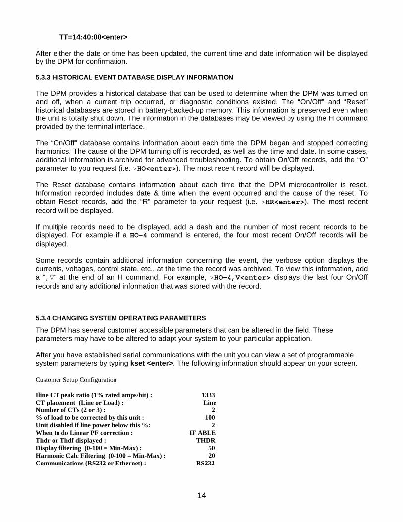
5.3.4 CHANGING SYSTEM OPERATING PARAMETERS
The DPM has several customer accessible parameters that can be altered in the field. These parameters may have to be altered to adapt your system to your particular application. After you have established serial communications with the unit you can view a set of programmable system parameters by typing kset <enter>. The following information should appear on your screen. Customer Setup Configuration Iline CT peak ratio (1% rated amps/bit) : 1333 CT placement (Line or Load) : Line Number of CTs (2 or 3) : 2 % of load to be corrected by this unit : 100 Unit disabled if line power below this %: 2 When to do Linear PF correction : IF ABLE Thdr or Thdf displayed : THDR Display filtering (0-100 = Min-Max) : 50 Harmonic Calc Filtering (0-100 = Min-Max) : 20 Communications (RS232 or Ethernet) : RS232

15
Note: The first three parameters listed above under the Customer Setup Configuration are not accessible by performing the following procedure. Please contact the factory if you find it necessary to change any one of the first three parameters. In order to change the customer accessible parameters under the Customer Setup Configuration you must perform the following numbered steps listed below. The <enter> designation is instructing you to hit the enter key. You may type either capital letters or lower case letters, the systems are not sensitive to the case used. If you make a mistake during this procedure, you may hit the escape key on the keyboard to abort the procedure. Aborting the procedure will result in no changes to any of the parameters being saved. 1. Type dcs <enter> 2. System should respond with “access OK” 3. Type kset;ch <enter> 4. System should respond with “CUSTOMER SETUP CONFIGURATION:” and then start listing each customer accessible parameter individually followed by the question “ADJUST (Y/N)?” 5. Type N<enter>until you reach the parameter you want to change 6. When you have reached the parameter you want to change type Y<enter> 7. If there are only two available choices for this parameter the system will change the parameter and move on to the next line. If there are more than two choices for a parameter the system will respond with “New Value” followed by a “_” prompt, or several numbered options to choose from. At this point you can respond by typing a numeric value after the “_” prompt followed by <enter>, or type in the number that corresponds to one of the choices followed by <enter>. 8. Answer N <enter>to all remaining “ADJUST (Y/N)?” questions until the “>” prompt is displayed indicating you have exited the parameter setup function 9. Type kset<enter> to verify that the parameter you selected has been changed Explanation of System Operating Parameters I Line CT Peak Ratio This is a system setting used to calibrate the DPM™ for proper operation with the specific line current sensors that have been shipped with the system. Consult factory if this value needs to be changed. CT Placement (Line or Load) This indicates the installation point of the current sensors relative to the installation point of the DPM™. Placement of the CTs on the line side is preferred for optimum system performance. CT placement on the load side of the DPM™ is required if more than one unit is being installed in parallel, or if line side CT placement is not possible. Consult factory if this value needs to be changed. Number of CTs This indicates the number of current sensors being used to monitor the three-phase line current. Standard installations require 2 current sensors. A third current sensor on phase C may be required if single-phase loads are present on the load side of the current sensor installation point. Consult factory if this value needs to be changed. % of load to be corrected by this Unit This indicates the % of correction that this unit is programmed to perform. A single unit is programmed to perform 100% correction. When two or more units are installed in parallel each unit must be programmed to perform a % of the total correction based on the number, and the current rating, of the units installed. For example; if two 100-amp units are installed in parallel in order to provide a total of 200 amps of correction then each unit will be programmed to correct for 50% of the load.

16
UNIT DISABLED IF LINE POWER BELOW THIS % In order to conserve energy, and to protect the system against potential damage due to improper installation, the DPM will stop operating unless the incoming line power read by the unit is > 2% of the power rating of the DPM and unit will not initialize itself, and begin operation unless the incoming line power read by the unit is 5% (or 3% higher than the “unit disable” programmed value). The power rating of the unit is equal to .83 kW per amp of correction, Ex. 100-amp DPM = 83 kW. This value can be changed by the customer if needed for certain installation requirements, but a value of 2% is recommended for normal operating conditions. A value of 0% can be entered if you would like to enable the system without a load. When to do linear PF correction When the “If Able” selection is chosen for this parameter the Mesta DPM will provide, harmonic correction, linear power factor correction, and line balancing, as long as the unit has sufficient current capacity available to perform linear power factor correction and line balancing after harmonic correction has been performed. If linear power factor correction and line balancing are not required the unit can be programmed to provide harmonic correction only by selecting the “Never” option. The “Always” option results in an equal effort being made for all 3 corrections regardless of whether or not the system is at maximum capacity. The “Never” option will result in the best harmonic elimination performance, while the other two choices will usually result in the highest power factor from the utility. The “If Able” option will result in better harmonic elimination performance than the “Always” option if the system is operated at maximum capacity; however, the “Always” option may result in a higher power factor from the utility (if not at maximum capacity, there should be little difference between the “If Able” and “Always” options. Thdr or Thdf displayed This parameter indicates which value for total harmonic distortion % is displayed in the Mesta DPM Status display. Thdr displays the total harmonic distortion as a % of the total RMS current drawn by the load. Thdf displays the total harmonic distortion as a % of the fundamental 60 Hz current drawn by the load. Display Filtering This indicates the amount of filtering performed prior to displaying the values shown in the Mesta DPM Status Display. The higher the value, the heavier the filtering. Harmonic Calc Filtering This indicates the amount of filtering performed when calculating the harmonic distortion displayed by the DPM. The higher the value, the heavier the filtering.
Communications
This indicates whether the RS232 serial communications or the Ethernet communications is active on the system. Note: changing this parameter from RS232 to Ethernet while communicating over the RS232 serial interface, or changing this parameter from Ethernet to RS232 while communicating over the Ethernet interface, will immediately result in loss of communications in the mode. Note: there is a jumper J1 on the Interface board in the system (small 2” x 8” printed circuit board located next to the main control board in the system) that overrides this setting if in any other position than the “N” (NORMAL) position. The “N” position is the default position from the factory for this jumper.

17
APPENDIX A. DPM SPECIFICATIONS BY MODEL
This section of the Mesta Electronics Owner's Manual contains a set of operating specifications for the model that you have purchased.

3ACDPM050/480 – 50 AMP 3 DPM SPECIFICATIONS POWER
Voltage 480VAC 3 Delta Nominal Current 50 Ampsrms correction current Crest Factor Capability 3.0 Frequency 60Hz 5Hz
OVERLOAD PROTECTION Output is electronically current limited to 300%
peak, 100% rms load rating Fuses provide backup protection to electronic
current limit Over temperature protection
PERFORMANCE Total Current Distortion (TCD) <5%, with no
individual harmonic exceeding 3% Power Factor 1.0 (Unity) Displacement Power Factor 1.0 (Unity) Efficiency >97% overall at full rating
INDICATORS AND CONTROLS LCD TOUCH SCREEN provides detailed
information on , AC line, load, and system operating parameters
LCD TOUCH SCREEN Perform system run, stop and menu functions
RS232 Interface for remote communications of status and diagnostics
Relay Contacts provides status contacts capable of 24V/0.1A operation
Ethernet Interface (Optional) for remote communications of status and diagnostics
PHYSICAL
Operating Temp 0ºC to 40ºC ambient without derating
Humidity Maximum 95% non-condensing Storage Temp -20ºC to 40ºC Thermal Internal forced air Audible Noise 55 dBA Power hardwired to internal circuit breaker Enclosure NEMA 1 Filters 12”x16”x1” (fiberglass type) Dimensions height 56", depth 14", width 20" Weight 275 lbs (125 Kg) Color Grey
OPTIONS 50 Hz Models and other voltages NOTE: For any of the above options, consult factory.

19
APPENDIX B. CUSTOMER INSTALLATION DIAGRAM
This section of the manual contains an installation diagram for the specific model DPM that has been purchased.


21
APPENDIX C. WARRANTY/SERVICE AND REPAIR
LIMITED WARRANTY POLICY
Mesta Electronics, Inc. warrants its Digital Power Factor and Harmonics Manager (DPM) to be free from defects in materials and workmanship for a period of 1 year from the date of original shipment from the factory, provided the DPM has not been abused, misused, or used outside of the specified conditions. Mesta Electronics, Inc. will be the sole determiner as to whether the unit has been abused or misused. If found to be defective, the unit will be repaired or replaced at the discretion of Mesta Electronics, Inc. Unless specified by contract, warranty service can only be obtained by returning the equipment to the Mesta factory.
Before returning any unit, in or out of warranty, to Mesta Electronics, purchaser must contact Mesta's Customer Service Department. Any UNAUTHORIZED return of a unit to Mesta Electronics for in-warranty or out-of-warranty repairs will be subject to an inspection and handling charge, in addition to all associated repair and transportation costs. Mesta Electronics, Inc. will be in no way responsible for any consequential damages of any kind or nature whatsoever resulting from the use of its unit in any manner whatsoever and/or from the breach of any warranty, express or implied.

REV 2.13 (04-10)
Mesta Electronics, Inc Pioneers in Power Electronics!

MESTA ELECTRONICS, INC. 11020 Parker Drive N. Huntingdon, PA 15642
412/754-3000