Embed Size (px)
Citation preview
2-347-773-15 (1)
© 2003 Sony Corporation
Digital PortableMixer
Operating InstructionsBefore operating the unit, please read this manual thoroughly andretain it for future reference.
DMX-P01

2
Owner’s RecordThe model and serial numbers are locatedon the rear. Record the serial numbers inthe spaces provided below. Refer to themwhenever you call upon your Sony dealerregarding the product.
Model No. DMX-P01Serial No.______________
WARNING
To reduce the risk of fire or electricshock, do not expose thisapparatus to rain or moisture.
To avoid electrical shock, do notopen the cabinet. Refer servicing toqualified personnel only.
CAUTIONThe apparatus shall not be exposed todripping or splashing. No objects filledwith liquids, such as vases, shall be placedon the apparatus.
WARNINGExcessive sound pressure from earphonesand headphones can cause hearing loss.In order to use this product safely, avoidprolonged listening at excessive soundpressure levels.
Batteries shall not be exposed to excessiveheat such as sunshine, fire or the like.
For the customers in the U.S.A.This equipment has been tested and foundto comply with the limits for a Class Adigital device, pursuant to Part 15 of theFCC Rules. These limits are designed toprovide reasonable protection againstharmful interference when the equipmentis operated in a commercial environment.This equipment generates, uses, and canradiate radio frequency energy and, if not
installed and used in accordance with theinstruction manual, may cause harmfulinterference to radio communications.Operation of this equipment in aresidential area is likely to cause harmfulinterference in which case the user will berequired to correct the interference at hisown expense.
You are cautioned that any changes ormodifications not expressly approved inthis manual could void your authority tooperate this equipment.
All interface cables used to connectperipherals must be shielded in order tocomply with the limits for a digital devicepursuant to Subpart B of Part 15 of FCCRules.
This device complies with Part 15 of theFCC Rules. Operation is subject to thefollowing two conditions: (1) this devicemay not cause harmful interference, and(2) this device must accept anyinterference received, includinginterference that may cause undesiredoperation.
For the customers in CanadaThis Class A digital apparatus complieswith Canadian ICES-003.
For the customers in EuropeThis product with the CE markingcomplies with the EMC Directive issuedby the Commission of the EuropeanCommunity.Compliance with this directive impliesconformity to the following Europeanstandards:• EN55103-1 : Electromagnetic
Interference(Emission)• EN55103-2 : Electromagnetic
Susceptibility(Immunity)This product is intended for use in thefollowing Electromagnetic Environments:
3
E1 (residential), E2 (commercial and lightindustrial), E3 (urban outdoors), E4(controlled EMC environment, ex. TVstudio).
This product has been manufactured by oron behalf of Sony Corporation, 1-7-1Konan Minato-ku Tokyo, 108-0075 Japan.Inquiries related to product compliancebased on European Union legislation shallbe addressed to the authorizedrepresentative, Sony Deutschland GmbH,Hedelfinger Strasse 61, 70327 Stuttgart,Germany. For any service or guaranteematters, please refer to the addressesprovided in the separate service orguarantee documents.
4
Table of Contents
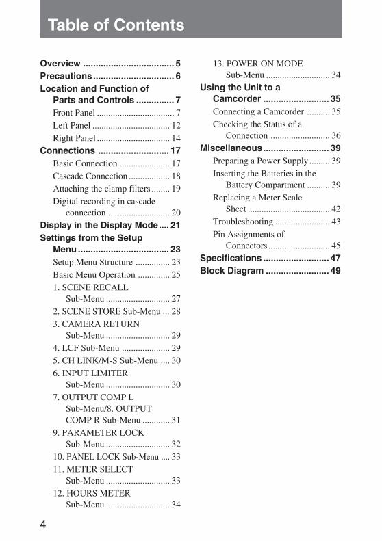
Overview .................................... 5Precautions................................ 6Location and Function of
Parts and Controls ............... 7Front Panel .................................. 7Left Panel .................................. 12Right Panel ................................ 14
Connections ............................ 17Basic Connection ...................... 17Cascade Connection .................. 18Attaching the clamp filters ........ 19Digital recording in cascade
connection ........................... 20Display in the Display Mode.... 21Settings from the Setup
Menu .................................... 23Setup Menu Structure ............... 23Basic Menu Operation .............. 251. SCENE RECALL
Sub-Menu ............................ 272. SCENE STORE Sub-Menu ... 283. CAMERA RETURN
Sub-Menu ............................ 294. LCF Sub-Menu ..................... 295. CH LINK/M-S Sub-Menu .... 306. INPUT LIMITER
Sub-Menu ............................ 307. OUTPUT COMP L
Sub-Menu/8. OUTPUTCOMP R Sub-Menu ............ 31
9. PARAMETER LOCKSub-Menu ............................ 32
10. PANEL LOCK Sub-Menu .... 3311. METER SELECT
Sub-Menu ............................ 3312. HOURS METER
Sub-Menu ............................ 34
13. POWER ON MODESub-Menu ............................ 34
Using the Unit to aCamcorder .......................... 35Connecting a Camcorder .......... 35Checking the Status of a
Connection .......................... 36Miscellaneous.......................... 39
Preparing a Power Supply ......... 39Inserting the Batteries in the
Battery Compartment .......... 39Replacing a Meter Scale
Sheet .................................... 42Troubleshooting ........................ 43Pin Assignments of
Connectors ........................... 45Specifications .......................... 47Block Diagram ......................... 49
5
Overview
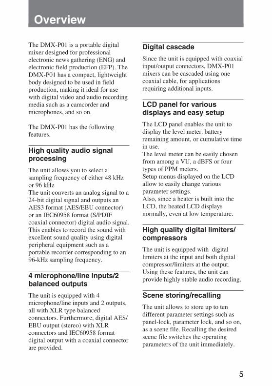
The DMX-P01 is a portable digitalmixer designed for professionalelectronic news gathering (ENG) andelectronic field production (EFP). TheDMX-P01 has a compact, lightweightbody designed to be used in fieldproduction, making it ideal for usewith digital video and audio recordingmedia such as a camcorder andmicrophones, and so on.
The DMX-P01 has the followingfeatures.
High quality audio signalprocessing
The unit allows you to select asampling frequency of either 48 kHzor 96 kHzThe unit converts an analog signal to a24-bit digital signal and outputs anAES3 format (AES/EBU connector)or an IEC60958 format (S/PDIFcoaxial connector) digital audio signal.This enables to record the sound withexcellent sound quality using digitalperipheral equipment such as aportable recorder corresponding to an96-kHz sampling frequency.
4 microphone/line inputs/2balanced outputs
The unit is equipped with 4microphone/line inputs and 2 outputs,all with XLR type balancedconnectors. Furthermore, digital AES/EBU output (stereo) with XLRconnectors and IEC60958 formatdigital output with a coaxial connectorare provided.
Digital cascade
Since the unit is equipped with coaxialinput/output connectors, DMX-P01mixers can be cascaded using onecoaxial cable, for applicationsrequiring additional inputs.
LCD panel for variousdisplays and easy setup
The LCD panel enables the unit todisplay the level meter. batteryremaining amount, or cumulative timein use.The level meter can be easily chosenfrom among a VU, a dBFS or fourtypes of PPM meters.Setup menus displayed on the LCDallow to easily change variousparameter settings.Also, since a heater is built into theLCD, the heated LCD displaysnormally, even at low temperature.
High quality digital limiters/compressors
The unit is equipped with digitallimiters at the input and both digitalcompressor/limiters at the output.Using these features, the unit canprovide highly stable audio recording.
Scene storing/recalling
The unit allows to store up to tendifferent parameter settings such aspanel-lock, parameter lock, and so on,as a scene file. Recalling the desiredscene file switches the operatingparameters of the unit immediately.
6
Full parameter controls onthe front panel similar tothose of analog mixers
Controls and switches are logicallylaid out on the front panel to allowfast, easy and accurate settingadjustments. Also, the panel-lockfunction prevents you from operatingthe unit accidentally.
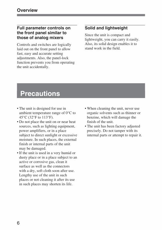
Precautions
• The unit is designed for use inambient temperature range of 0°C to45°C (32°F to 113°F).
• Do not place the unit on or near heatsources, such as lighting equipment,power amplifiers, or in a placesubject to direct sunlight or excessivemoisture. In such places, the externalfinish or internal parts of the unitmay be damaged.
• If the unit is used in a very humid ordusty place or in a place subject to anactive or corrosive gas, clean itsurface as well as the connectorswith a dry, soft cloth soon after use.Lengthy use of the unit in suchplaces or not cleaning it after its usein such places may shorten its life.
Solid and lightweight
Since the unit is compact andlightweight, you can carry it easily.Also, its solid design enables it tostand work in the field.
• When cleaning the unit, never useorganic solvents such as thinner orbenzine, which will damage thefinish of the unit.
• The unit has been factory adjustedprecisely. Do not tamper with itsinternal parts or attempt to repair it.
Overview
7
Location and Function of Parts andControls
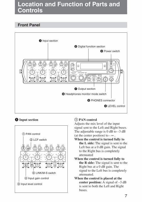
Front Panel
1 Input section
2 Digital function section
3 Power switch
4 LEVEL control
5 PHONES connector
6 Headphones monitor mode switch
7 Output section
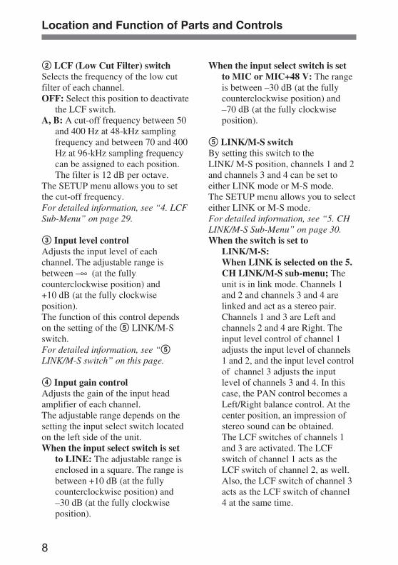
1 Input section 1 PAN controlAdjusts the mix level of the inputsignal sent to the Left and Right buses.The adjustable range is 0 dB to –3 dB(at the center position) to - ∞ .When the control is turned fully to
the L side: The signal is sent to theLeft bus at a 0 dB gain. The signalto the Right bus is completelyattenuated
When the control is turned fully tothe R side: The signal is sent to theRight bus at a 0 dB gain. Thesignal to the Left bus is completelyattenuated.
When the control is placed at thecenter position: A signal of –3 dBis sent to both the Left and Rightbuses.
1 PAN control
2 LCF switch
3 Input level control
4 Input gain control
5 LINK/M-S switch
8
Location and Function of Parts and Controls
2 LCF (Low Cut Filter) switchSelects the frequency of the low cutfilter of each channel.OFF: Select this position to deactivate
the LCF switch.A, B: A cut-off frequency between 50
and 400 Hz at 48-kHz samplingfrequency and between 70 and 400Hz at 96-kHz sampling frequencycan be assigned to each position.The filter is 12 dB per octave.
The SETUP menu allows you to setthe cut-off frequency.For detailed information, see “4. LCFSub-Menu” on page 29.
3 Input level controlAdjusts the input level of eachchannel. The adjustable range isbetween –∞ (at the fullycounterclockwise position) and+10 dB (at the fully clockwiseposition).The function of this control dependson the setting of the 5 LINK/M-Sswitch.For detailed information, see “5LINK/M-S switch” on this page.
4 Input gain controlAdjusts the gain of the input headamplifier of each channel.The adjustable range depends on thesetting the input select switch locatedon the left side of the unit.When the input select switch is set
to LINE: The adjustable range isenclosed in a square. The range isbetween +10 dB (at the fullycounterclockwise position) and–30 dB (at the fully clockwiseposition).
When the input select switch is setto MIC or MIC+48 V: The rangeis between –30 dB (at the fullycounterclockwise position) and–70 dB (at the fully clockwiseposition).
5 LINK/M-S switchBy setting this switch to theLINK/ M-S position, channels 1 and 2and channels 3 and 4 can be set toeither LINK mode or M-S mode.The SETUP menu allows you to selecteither LINK or M-S mode.For detailed information, see “5. CHLINK/M-S Sub-Menu” on page 30.When the switch is set to
LINK/M-S:When LINK is selected on the 5.CH LINK/M-S sub-menu; Theunit is in link mode. Channels 1and 2 and channels 3 and 4 arelinked and act as a stereo pair.Channels 1 and 3 are Left andchannels 2 and 4 are Right. Theinput level control of channel 1adjusts the input level of channels1 and 2, and the input level controlof channel 3 adjusts the inputlevel of channels 3 and 4. In thiscase, the PAN control becomes aLeft/Right balance control. At thecenter position, an impression ofstereo sound can be obtained.The LCF switches of channels 1and 3 are activated. The LCFswitch of channel 1 acts as theLCF switch of channel 2, as well.Also, the LCF switch of channel 3acts as the LCF switch of channel4 at the same time.
9
When M-S is selected on the 5.CH LINK/M-S sub-menu; Theunit is in M-S mode.Select this position for M-Sdecoding when an M-Smicrophone is used.Connect channel 1 and channel 3to the M side and channel 2 andchannel 4 to the S side. In such acase, the input level control of theCH-1 and CH-3 act as an inputlevel control and the input levelcontrols of the CH-2 and CH-4 actas a phase control. Turning thephase control to the right providesan expansive feeling.
When the switch is set to OFF:Controls and switches act as thoseof each channel, independently.
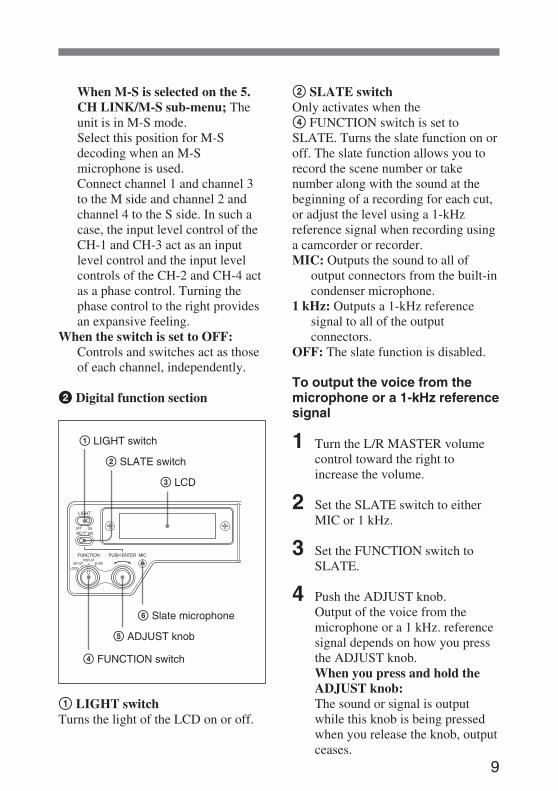
2 Digital function section
1 LIGHT switchTurns the light of the LCD on or off.
1 LIGHT switch
2 SLATE switch
3 LCD
4 FUNCTION switch
5 ADJUST knob
6 Slate microphone
2 SLATE switchOnly activates when the4 FUNCTION switch is set toSLATE. Turns the slate function on oroff. The slate function allows you torecord the scene number or takenumber along with the sound at thebeginning of a recording for each cut,or adjust the level using a 1-kHzreference signal when recording usinga camcorder or recorder.MIC: Outputs the sound to all of
output connectors from the built-incondenser microphone.
1 kHz: Outputs a 1-kHz referencesignal to all of the outputconnectors.
OFF: The slate function is disabled.
To output the voice from themicrophone or a 1-kHz referencesignal
1 Turn the L/R MASTER volumecontrol toward the right toincrease the volume.
2 Set the SLATE switch to eitherMIC or 1 kHz.
3 Set the FUNCTION switch toSLATE.
4 Push the ADJUST knob.Output of the voice from themicrophone or a 1 kHz. referencesignal depends on how you pressthe ADJUST knob.When you press and hold theADJUST knob:The sound or signal is outputwhile this knob is being pressedwhen you release the knob, outputceases.
10
Location and Function of Parts and Controls
When you press the knob andrelease it instantly:When you press the knob andrelease it instantly, the sound orsignal continues to be output.When you press the knob andrelease it again, output ceases.
3 LCD (Liquid Crystal Display)What is displayed depends on thesetting of the FUNCTION switch.For detailed information, see “4FUNCTION switch.”A heater is built into the LCD to beused in cold weather. This preventsthe LCD from slowing down thedisplay speed. The temperature isdetected and the heater isautomatically turned on or off.
Note
This heater is activated only with anexternal power supply. When thepower is supplied from the batteries,the heater is not activated.
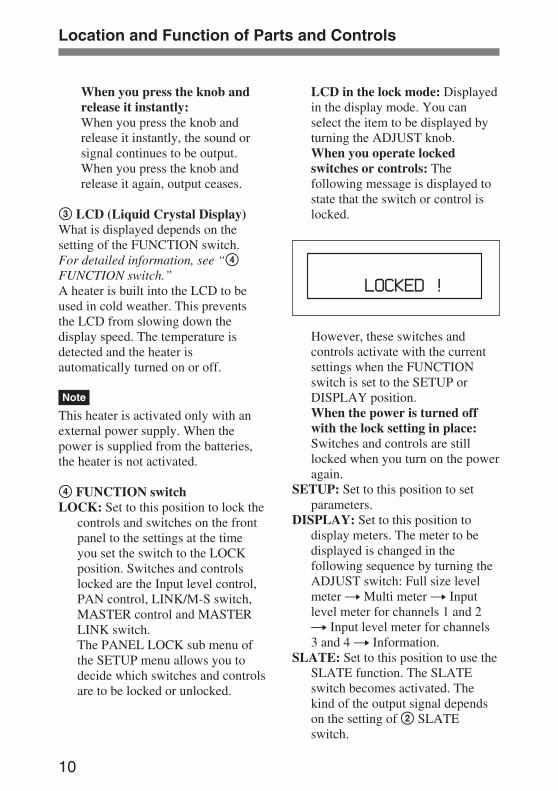
4 FUNCTION switchLOCK: Set to this position to lock the
controls and switches on the frontpanel to the settings at the timeyou set the switch to the LOCKposition. Switches and controlslocked are the Input level control,PAN control, LINK/M-S switch,MASTER control and MASTERLINK switch.The PANEL LOCK sub menu ofthe SETUP menu allows you todecide which switches and controlsare to be locked or unlocked.
LCD in the lock mode: Displayedin the display mode. You canselect the item to be displayed byturning the ADJUST knob.When you operate lockedswitches or controls: Thefollowing message is displayed tostate that the switch or control islocked.
However, these switches andcontrols activate with the currentsettings when the FUNCTIONswitch is set to the SETUP orDISPLAY position.When the power is turned offwith the lock setting in place:Switches and controls are stilllocked when you turn on the poweragain.
SETUP: Set to this position to setparameters.
DISPLAY: Set to this position todisplay meters. The meter to bedisplayed is changed in thefollowing sequence by turning theADJUST switch: Full size levelmeter t Multi meter t Inputlevel meter for channels 1 and 2t Input level meter for channels3 and 4 t Information.
SLATE: Set to this position to use theSLATE function. The SLATEswitch becomes activated. Thekind of the output signal dependson the setting of 2 SLATEswitch.
11
5 ADJUST (PUSH ENTER) knobUsed for menu operations. Select amenu by turning the knob and executeby pressing the knob.When the SLATE function is on, thisswitch acts as the slate signal outputbutton.
6 Slate microphoneThis built-in condenser microphone isactivated when the ADJUST knob ispressed.For detailed information on how tooutput voice from the microphone, see“To output the voice from themicrophone or a 1-kHz referencesignal” on page 9.
3 Power switchTurns the power on or off.When the power is on, the externalpower supply is selected automaticallywhen the power is supplied externally.If the internal batteries are inserted,the power supply is not interruptedeven if you disconnect and re-connectthe external power supply. Also, youcan change the internal batterieswithout interrupting operations whenyou use the external power supply.
4 LEVEL controlAdjusts the headphones volume level.
5 PHONES connector (stereophone jack)Connects the headphones. The samesignal as the one from the PHONESconnector located on the right side ofthe unit is output.The signal to be output depends on thesetting of the 6 Headphones monitormode switch.
6 Headphones monitor modeswitchSelects the signal to be monitoredthrough the headphones.L/R: Outputs the Left signal of the
master output signal to the Leftchannel and the Right signal to theRight channel as stereo.
L+R: Outputs a mixed signal of themaster output signal to both Leftand Right channels as mono.
L: Outputs the Left signal of themaster output signal to both Leftand Right channels.
R: Outputs the Right signal of themaster output signal to both Leftand Right channels.
M-S: Outputs the M/S decoded signalto the PHONES connector. Selectthis position when the M-S (Mid-Side) microphone is used and onlythe output signal to the PHONESconnector is to be decoded.
CAMERA: Outputs the signal fromthe camcorder input to theCAMERA connector located onthe right side.
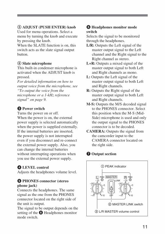
7 Output section
1 PEAK indicator
2 MASTER LINK switch
3 L/R MASTER volume control
12
Location and Function of Parts and Controls
1 PEAK indicatorLights in red when the output signalreaches –3 dB from a clipping level.When the output compressors/limitersactivate, this indicator lights toindicate the compressor/limiteroperations, as follows.When the input level exceeds thepreset threshold level, the outputcompressors activate and the indicatorlights in orange.When the input level exceeds thepreset threshold level, the limitersactivate and the indicator lights in red.The OUTPUT COMP L and OUTPUTCOMP R sub-menus of the SETUPmenu allow you to make settings ofthe threshold level for thecompressors/limiters.
2 MASTER LINK switchSetting the switch to the LINKposition links the Left channel outputand Right channel output of the masteroutput. The L MASTER volumecontrol adjusts the output level of bothchannels. In this case, the R MASTERvolume control is not activated. Thisfunction is not applied to the outputcompressor/limiter.
3 L/R MASTER volume controlAdjusts the output level. Theadjustable range is – ∞ dB at the fullycounterclockwise position, 0 dB and+10 dB at the fully clockwise position.
Left Panel
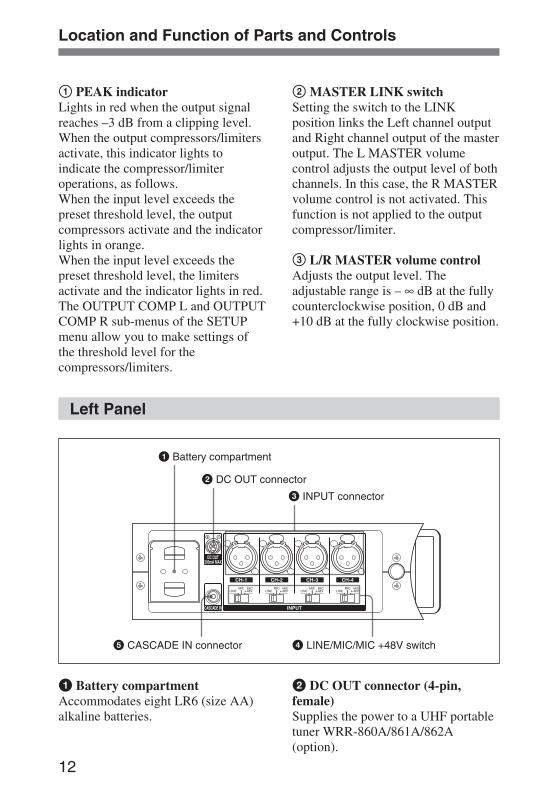
1 Battery compartment
2 DC OUT connector
3 INPUT connector
4 LINE/MIC/MIC +48V switch5 CASCADE IN connector
1 Battery compartmentAccommodates eight LR6 (size AA)alkaline batteries.
2 DC OUT connector (4-pin,female)Supplies the power to a UHF portabletuner WRR-860A/861A/862A(option).

13
Notes
• Be sure not to connect devices otherthan a UHF portable tuner.
• The unit outputs the power, onlywhen the unit operates with anexternal power supply.This connector outputs the power bydividing the power input via theDC IN 10-15 V connector. Thus theoutput voltage depends on the powerinput via the DC IN 10 - 15 Vconnector.
3 INPUT (analog signal input)connectors (XLR type 3-pin, female)Input the analog audio signals of thefour channels CH1, CH2, CH3 andCH4.
4 LINE/MIC/MIC +48V switchSelects the position to match theincoming signal level of each channel.LINE: Set to this position when
connecting equipment with aninput signal level between+10 dBu and –30 dBu.
MIC: Set to this position whenconnecting the equipment with aninput signal between –30 dBu and–70 dBu, especially whenconnecting a microphone.
MIC +48V: Set to this position whenconnecting the equipment with aninput signal between –30 dBu and–70 dBu, especially whenconnecting a DC +48V powermicrophone.
5 CASCADE IN (Cascade signalinput) connector (Phono jack)Used for a cascade connection. Whenthis unit is as the second oneconnected, connect this connector tothe COAXIAL connector located onthe right panel of the first DMX-P01.This unit is synchronized with the firstDMX-P01 using the master clocksignal extracted from the signal of thisconnector.
Note
In a cascade connection, the samplingrate of both DMX-P01 mixers must bematched. Set the sampling rate tomatch using the SAMPLING RATEswitch.Also, do not input the IEC60958format signal to the CASCADEINPUT connector.
14
Location and Function of Parts and Controls
Right Panel
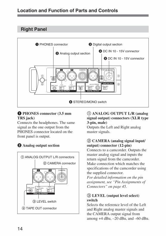
1 PHONES connector
2 Analog output section
3 Digital output section
4 DC IN 10 - 15V connector
6 STEREO/MONO switch
5 DC IN 10 - 15V connector
1 PHONES connector (3.5 mmTRS jack)Connects the headphones. The samesignal as the one output from thePHONES connector located on thefront panel is output.
2 Analog output section
1 ANALOG OUTPUT L/R connectors
2 CAMERA connector
3 LEVEL switch
4 TAPE OUT connector
1 ANALOG OUTPUT L/R (analogsignal output) connectors (XLR type3-pin, male)Outputs the Left and Right analogmaster signals.
2 CAMERA (analog signal input/output) connector (12-pin)Connects to a camcorder. Outputs themaster analog signal and inputs thereturn signal from the camcorder.Make connection which matches thespecifications of the camcorder usingthe supplied connector.For detailed information on the pinassignment, see “Pin Assignments ofConnectors” on page 45.
3 LEVEL (output level select)switchSelects the reference level of the Leftand Right analog master signals andthe CAMERA output signal fromamong +4 dBu, –20 dBu, and –60 dBu.
15
4 TAPE OUT (analog signaloutput) connector (3.5mm TRSjack)Outputs an unbalanced stereo analogsignal. The reference level is fixed to–10 dBu.
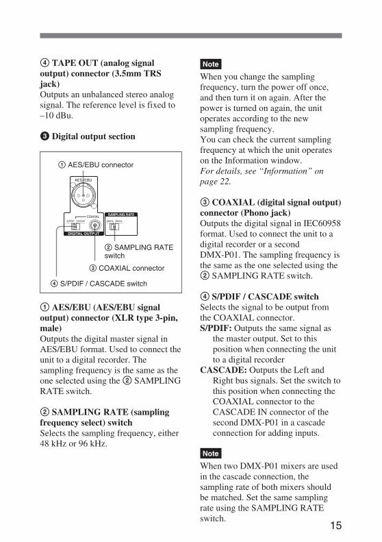
3 Digital output section
1 AES/EBU (AES/EBU signaloutput) connector (XLR type 3-pin,male)Outputs the digital master signal inAES/EBU format. Used to connect theunit to a digital recorder. Thesampling frequency is the same as theone selected using the 2 SAMPLINGRATE switch.
2 SAMPLING RATE (samplingfrequency select) switchSelects the sampling frequency, either48 kHz or 96 kHz.
1 AES/EBU connector
2 SAMPLING RATEswitch
3 COAXIAL connector
4 S/PDIF / CASCADE switch
Note
When you change the samplingfrequency, turn the power off once,and then turn it on again. After thepower is turned on again, the unitoperates according to the newsampling frequency.You can check the current samplingfrequency at which the unit operateson the Information window.For details, see “Information” onpage 22.
3 COAXIAL (digital signal output)connector (Phono jack)Outputs the digital signal in IEC60958format. Used to connect the unit to adigital recorder or a secondDMX-P01. The sampling frequency isthe same as the one selected using the2 SAMPLING RATE switch.
4 S/PDIF / CASCADE switchSelects the signal to be output fromthe COAXIAL connector.S/PDIF: Outputs the same signal as
the master output. Set to thisposition when connecting the unitto a digital recorder
CASCADE: Outputs the Left andRight bus signals. Set the switch tothis position when connecting theCOAXIAL connector to theCASCADE IN connector of thesecond DMX-P01 in a cascadeconnection for adding inputs.
Note
When two DMX-P01 mixers are usedin the cascade connection, thesampling rate of both mixers shouldbe matched. Set the same samplingrate using the SAMPLING RATEswitch.
16
4 DC IN 10 - 15 V (external powerinput) connector (DC jack type)/5 DC IN 10 - 15 V (external powerinput) connector (XLR type 4-pin,male)Inputs the 10 to 15 V DC externalpower.
Notes
• An external battery other than BP-90type battery cannot be connected to4 DC IN 10 - 15 V (DC jack type)connector because the polarity of theDC jack is different.
• Do not connect external batteries toboth 4 DC IN 10 - 15 V connector(DC jack type) and 5 DC IN 10 - 15V connector (XLR type 4-pin) at thesame time. Be sure to connect theexternal battery to either one.
6 STEREO/MONO (stereo/monoselect) switchChanges signals to be output from allof the output connectors to eitherstereo or mono.
Location and Function of Parts and Controls
17
Connections
Note
Before making connections, be sureto turn the power of any peripheralequipment off.
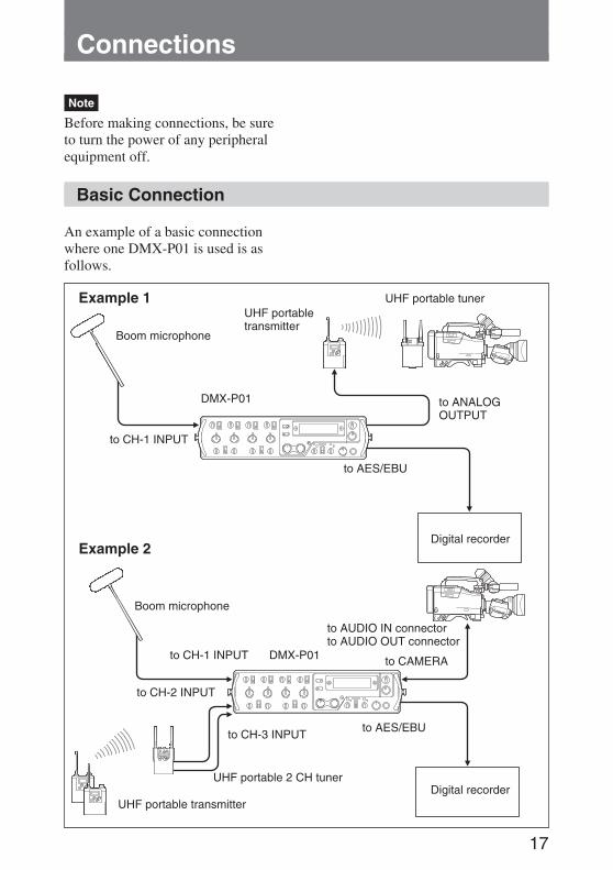
Basic Connection
An example of a basic connectionwhere one DMX-P01 is used is asfollows.
Example 1
Boom microphone
to CH-1 INPUT
DMX-P01
UHF portabletransmitter
UHF portable tuner
to ANALOGOUTPUT
Digital recorderExample 2
Boom microphone
to CH-1 INPUT DMX-P01
to CH-2 INPUT
to CH-3 INPUT
UHF portable 2 CH tuner
UHF portable transmitter
to AES/EBU
to AUDIO IN connectorto AUDIO OUT connector
to CAMERA
Digital recorder
to AES/EBU
18
Connections
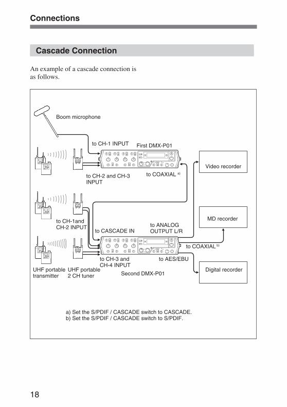
Cascade Connection
An example of a cascade connection isas follows.
Boom microphone
to CH-1 INPUT First DMX-P01
to COAXIAL a)
Video recorder
to CH-1andCH-2 INPUT
to CASCADE INto ANALOGOUTPUT L/R
MD recorder
to COAXIAL b)
to CH-2 and CH-3INPUT
UHF portable2 CH tuner
to AES/EBU
Second DMX-P01Digital recorderUHF portable
transmitter
a) Set the S/PDIF / CASCADE switch to CASCADE.b) Set the S/PDIF / CASCADE switch to S/PDIF.
to CH-3 andCH-4 INPUT
19
Attaching the clampfilters
Caution
For customers in Europe
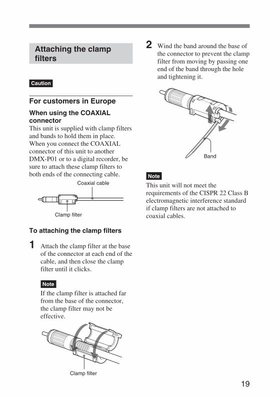
When using the COAXIALconnectorThis unit is supplied with clamp filtersand bands to hold them in place.When you connect the COAXIALconnector of this unit to anotherDMX-P01 or to a digital recorder, besure to attach these clamp filters toboth ends of the connecting cable.
To attaching the clamp filters
1 Attach the clamp filter at the baseof the connector at each end of thecable, and then close the clampfilter until it clicks.
Note
If the clamp filter is attached farfrom the base of the connector,the clamp filter may not beeffective.
2 Wind the band around the base ofthe connector to prevent the clampfilter from moving by passing oneend of the band through the holeand tightening it.
Note
This unit will not meet therequirements of the CISPR 22 Class Belectromagnetic interference standardif clamp filters are not attached tocoaxial cables.
Coaxial cable
Clamp filter
Clamp filter
Band
20
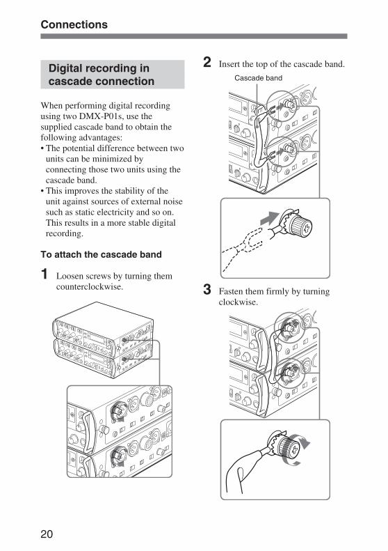
Digital recording incascade connection
When performing digital recordingusing two DMX-P01s, use thesupplied cascade band to obtain thefollowing advantages:• The potential difference between two
units can be minimized byconnecting those two units using thecascade band.
• This improves the stability of theunit against sources of external noisesuch as static electricity and so on.This results in a more stable digitalrecording.
To attach the cascade band
1 Loosen screws by turning themcounterclockwise.
2 Insert the top of the cascade band.
3 Fasten them firmly by turningclockwise.
Cascade band
Connections
21
Display in the Display Mode
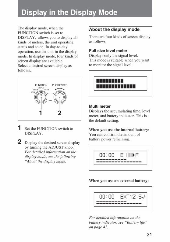
The display mode, when theFUNCTION switch is set toDISPLAY, allows you to display allkinds of meters, the unit operatingstatus and so on. In day-to-dayoperation, use the unit in the displaymode. In display mode, four kinds ofscreen display are available.Select a desired screen display asfollows.
1 2
1 Set the FUNCTION switch toDISPLAY.
2 Display the desired screen displayby turning the ADJUST knob.For detailed information on thedisplay mode, see the following“About the display mode.”
About the display mode
There are four kinds of screen display,as follows.
Full size level meterDisplays only the signal level.This mode is suitable when you wantto monitor the signal level.
Multi meterDisplays the accumulating time, levelmeter, and battery indicator. This isthe default setting.
When you use the internal battery:You can confirm the amount ofbattery power remaining.
When you use an external battery:
For detailed information on thebattery indicator, see “Battery life”on page 41.
22
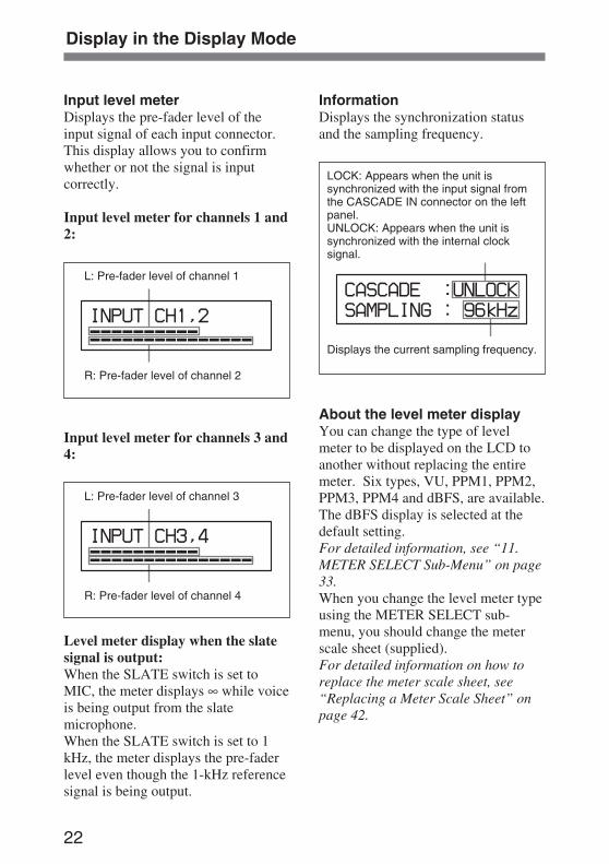
Input level meterDisplays the pre-fader level of theinput signal of each input connector.This display allows you to confirmwhether or not the signal is inputcorrectly.
Input level meter for channels 1 and2:
L: Pre-fader level of channel 1
R: Pre-fader level of channel 2
Input level meter for channels 3 and4:
L: Pre-fader level of channel 3
R: Pre-fader level of channel 4
Level meter display when the slatesignal is output:When the SLATE switch is set toMIC, the meter displays ∞ while voiceis being output from the slatemicrophone.When the SLATE switch is set to 1kHz, the meter displays the pre-faderlevel even though the 1-kHz referencesignal is being output.
InformationDisplays the synchronization statusand the sampling frequency.
LOCK: Appears when the unit issynchronized with the input signal fromthe CASCADE IN connector on the leftpanel.UNLOCK: Appears when the unit issynchronized with the internal clocksignal.
Displays the current sampling frequency.
About the level meter displayYou can change the type of levelmeter to be displayed on the LCD toanother without replacing the entiremeter. Six types, VU, PPM1, PPM2,PPM3, PPM4 and dBFS, are available.The dBFS display is selected at thedefault setting.For detailed information, see “11.METER SELECT Sub-Menu” on page33.When you change the level meter typeusing the METER SELECT sub-menu, you should change the meterscale sheet (supplied).For detailed information on how toreplace the meter scale sheet, see“Replacing a Meter Scale Sheet” onpage 42.
Display in the Display Mode
23
Settings from the Setup Menu
Setup Menu Structure
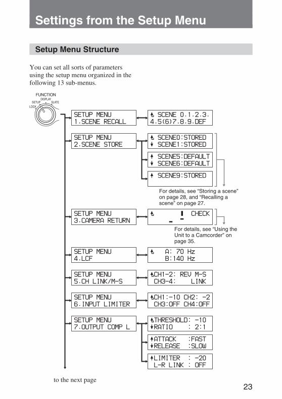
You can set all sorts of parametersusing the setup menu organized in thefollowing 13 sub-menus.
to the next page
For details, see “Using theUnit to a Camcorder” onpage 35.
For details, see “Storing a scene”on page 28, and “Recalling ascene” on page 27.
24
Settings from the Setup Menu
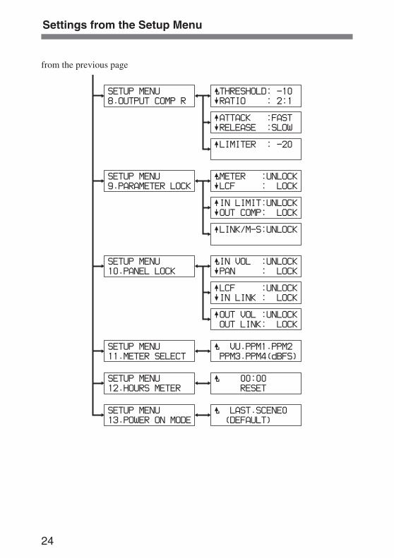
from the previous page
25
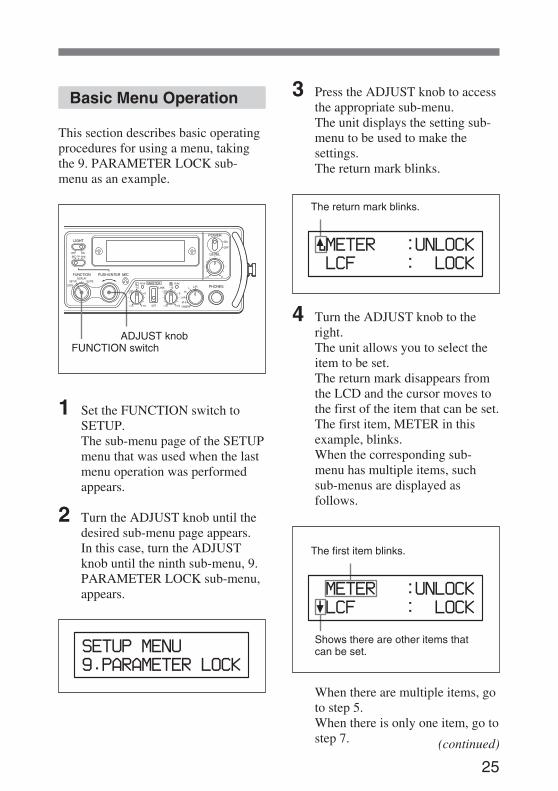
Basic Menu Operation
This section describes basic operatingprocedures for using a menu, takingthe 9. PARAMETER LOCK sub-menu as an example.
1 Set the FUNCTION switch toSETUP.The sub-menu page of the SETUPmenu that was used when the lastmenu operation was performedappears.
2 Turn the ADJUST knob until thedesired sub-menu page appears.In this case, turn the ADJUSTknob until the ninth sub-menu, 9.PARAMETER LOCK sub-menu,appears.
3 Press the ADJUST knob to accessthe appropriate sub-menu.The unit displays the setting sub-menu to be used to make thesettings.The return mark blinks.
The return mark blinks.
4 Turn the ADJUST knob to theright.The unit allows you to select theitem to be set.The return mark disappears fromthe LCD and the cursor moves tothe first of the item that can be set.The first item, METER in thisexample, blinks.When the corresponding sub-menu has multiple items, suchsub-menus are displayed asfollows.
The first item blinks.
Shows there are other items thatcan be set.
When there are multiple items, goto step 5.When there is only one item, go tostep 7.
ADJUST knobFUNCTION switch
(continued)
26
Settings from the Setup Menu
When you want to perform anoperation such as a reset (12.HOURS METER sub-menu), or acheck of an item (3. CAMERARETURN sub-menu) on theappropriate sub-menu, go to step7.
5 Turn the ADJUST knob until thedesired item blinks.Turning it to the right results inthe cursor moving to the nextitem, and turning it to the leftresults in the cursor moving to theprevious item.
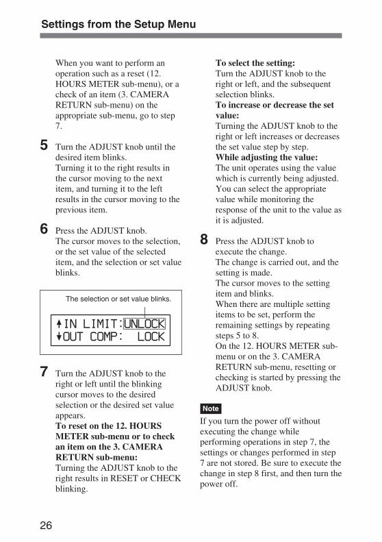
6 Press the ADJUST knob.The cursor moves to the selection,or the set value of the selecteditem, and the selection or set valueblinks.
The selection or set value blinks.
7 Turn the ADJUST knob to theright or left until the blinkingcursor moves to the desiredselection or the desired set valueappears.To reset on the 12. HOURSMETER sub-menu or to checkan item on the 3. CAMERARETURN sub-menu:Turning the ADJUST knob to theright results in RESET or CHECKblinking.
To select the setting:Turn the ADJUST knob to theright or left, and the subsequentselection blinks.To increase or decrease the setvalue:Turning the ADJUST knob to theright or left increases or decreasesthe set value step by step.While adjusting the value:The unit operates using the valuewhich is currently being adjusted.You can select the appropriatevalue while monitoring theresponse of the unit to the value asit is adjusted.
8 Press the ADJUST knob toexecute the change.The change is carried out, and thesetting is made.The cursor moves to the settingitem and blinks.When there are multiple settingitems to be set, perform theremaining settings by repeatingsteps 5 to 8.On the 12. HOURS METER sub-menu or on the 3. CAMERARETURN sub-menu, resetting orchecking is started by pressing theADJUST knob.
Note
If you turn the power off withoutexecuting the change whileperforming operations in step 7, thesettings or changes performed in step7 are not stored. Be sure to execute thechange in step 8 first, and then turn thepower off.
27
To move to another sub-menu
1 When the cursor blinks beside thesetting item just set, turn theADJUST knob to the left until thereturn mark to the left of the topsetting item appears and blinks.
2 Press the ADJUST knob.The sub-menu appears.
3 Turn the ADJUST knob to the leftor right until the desired sub-menuappears, and then press theADJUST knob.
When you cannot enter thesetting mode from the sub-menuThat sub-menu has been locked toprevent misoperation using 9.PARAMETER LOCK sub-menu. Toperform settings on that sub-menu,unlock it using the 9. PARAMETERLOCK sub-menu.
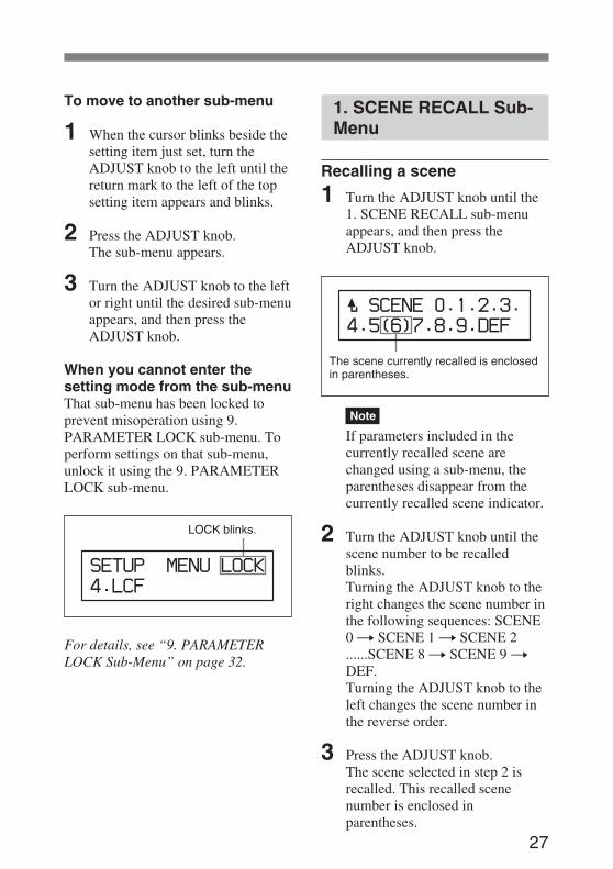
LOCK blinks.
For details, see “9. PARAMETERLOCK Sub-Menu” on page 32.
1. SCENE RECALL Sub-Menu
Recalling a scene
1 Turn the ADJUST knob until the1. SCENE RECALL sub-menuappears, and then press theADJUST knob.
The scene currently recalled is enclosedin parentheses.
Note
If parameters included in thecurrently recalled scene arechanged using a sub-menu, theparentheses disappear from thecurrently recalled scene indicator.
2 Turn the ADJUST knob until thescene number to be recalledblinks.Turning the ADJUST knob to theright changes the scene number inthe following sequences: SCENE0 t SCENE 1 t SCENE 2......SCENE 8 t SCENE 9 tDEF.Turning the ADJUST knob to theleft changes the scene number inthe reverse order.
3 Press the ADJUST knob.The scene selected in step 2 isrecalled. This recalled scenenumber is enclosed inparentheses.
28
Settings from the Setup Menu
2. SCENE STORE Sub-Menu
This sub-menu allows you to store tendifferent parameter settings as a scenefile from scenes nos. 0 to 9. Recallingthe desired scene changes the unit tothe desired setup immediately.
Parameters stored in a scenefileParameters set on sub-menus 4 to 11.
Note
For settings on the 10. PANEL LOCKsub-menu, only the locked switchesand controls are stored. To actuallylock those switches and controls, youshould set the FUNCTION switch tothe LOCK position.
Storing a scene
1 Turn the ADJUST knob until the2. SCENE STORE sub-menuappears, and then press theADJUST knob.
Status display section
2 Turn the ADJUST knob until thedesired scene number blinks.Turning the ADJUST knob to theright changes the scene number inthe following sequences: SCENE0 t SCENE 1 t SCENE 2......SCENE 8 t SCENE 9.
Turning the ADJUST knob to theleft changes the scene number inthe reverse order.The status display section showsthe status of each scene.
3 Press the ADJUST knob.The cursor moves to the statusdisplay section and CANCELappears there.
4 Turn the ADJUST knob to theright to display WRITE.Turning the ADJUST knob to theright changes the status displaysection in the following sequence:CANCEL t WRITE tERASE.To cancel the storing operationand return the cursor to thescene number selection area:Display CANCEL.
To reset the parameters to thedefault settings:Display ERASE.
5 Press the ADJUST knob toexecute the change.Parameters currently set are storedas a scene with the numberselected in step 2.
Display
DEFAULT
STORED
Status
The correspondingscene file is not used(parameters are defaultsettings).
The default settings areoverwritten (parametersother than the defaultsare stored).
29
3. CAMERA RETURNSub-Menu
This sub-menu allows you to checkwhether or not signal transmission andreception are correctly performedbetween the unit and a camcorder bytransmitting a 1-kHz reference signalfrom all of output connectors of theunit.By comparing the 1-kHz referencesignal sent from the unit with thesignal returned from the camcorder, anerror is detected. You can confirm theconnection status and adjust the outputlevel and recording according to theerror detected.For detailed information, see “Usingthe Unit to a Camcorder” on page 35.
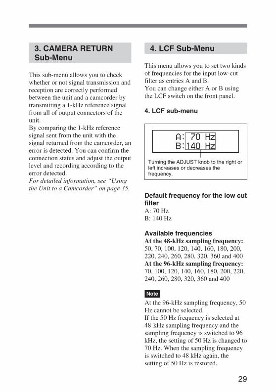
4. LCF Sub-Menu
This menu allows you to set two kindsof frequencies for the input low-cutfilter as entries A and B.You can change either A or B usingthe LCF switch on the front panel.
4. LCF sub-menu
Turning the ADJUST knob to the right orleft increases or decreases thefrequency.
Default frequency for the low cutfilterA: 70 HzB: 140 Hz
Available frequenciesAt the 48-kHz sampling frequency:50, 70, 100, 120, 140, 160, 180, 200,220, 240, 260, 280, 320, 360 and 400At the 96-kHz sampling frequency:70, 100, 120, 140, 160, 180, 200, 220,240, 260, 280, 320, 360 and 400
Note
At the 96-kHz sampling frequency, 50Hz cannot be selected.If the 50 Hz frequency is selected at48-kHz sampling frequency and thesampling frequency is switched to 96kHz, the setting of 50 Hz is changed to70 Hz. When the sampling frequencyis switched to 48 kHz again, thesetting of 50 Hz is restored.
30
Settings from the Setup Menu
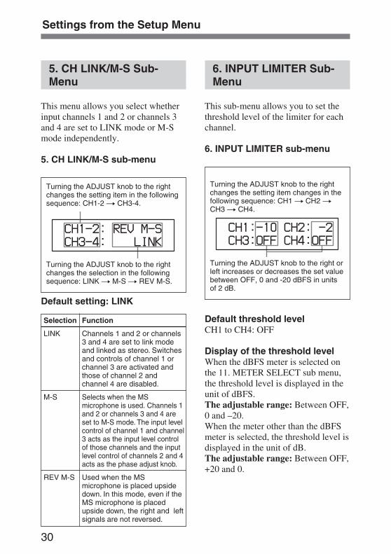
5. CH LINK/M-S Sub-Menu
This menu allows you select whetherinput channels 1 and 2 or channels 3and 4 are set to LINK mode or M-Smode independently.
5. CH LINK/M-S sub-menu
Turning the ADJUST knob to the rightchanges the setting item in the followingsequence: CH1-2 t CH3-4.
Turning the ADJUST knob to the rightchanges the selection in the followingsequence: LINK t M-S t REV M-S.
Default setting: LINK
6. INPUT LIMITER Sub-Menu
This sub-menu allows you to set thethreshold level of the limiter for eachchannel.
6. INPUT LIMITER sub-menu
Turning the ADJUST knob to the rightchanges the setting item changes in thefollowing sequence: CH1 t CH2 tCH3 t CH4.
Turning the ADJUST knob to the right orleft increases or decreases the set valuebetween OFF, 0 and -20 dBFS in unitsof 2 dB.
Default threshold levelCH1 to CH4: OFF
Display of the threshold levelWhen the dBFS meter is selected onthe 11. METER SELECT sub menu,the threshold level is displayed in theunit of dBFS.The adjustable range: Between OFF,0 and –20.When the meter other than the dBFSmeter is selected, the threshold level isdisplayed in the unit of dB.The adjustable range: Between OFF,+20 and 0.
Selection
LINK
M-S
REV M-S
Function
Channels 1 and 2 or channels3 and 4 are set to link modeand linked as stereo. Switchesand controls of channel 1 orchannel 3 are activated andthose of channel 2 andchannel 4 are disabled.
Selects when the MSmicrophone is used. Channels 1and 2 or channels 3 and 4 areset to M-S mode. The input levelcontrol of channel 1 and channel3 acts as the input level controlof those channels and the inputlevel control of channels 2 and 4acts as the phase adjust knob.
Used when the MSmicrophone is placed upsidedown. In this mode, even if theMS microphone is placedupside down, the right and leftsignals are not reversed.
31
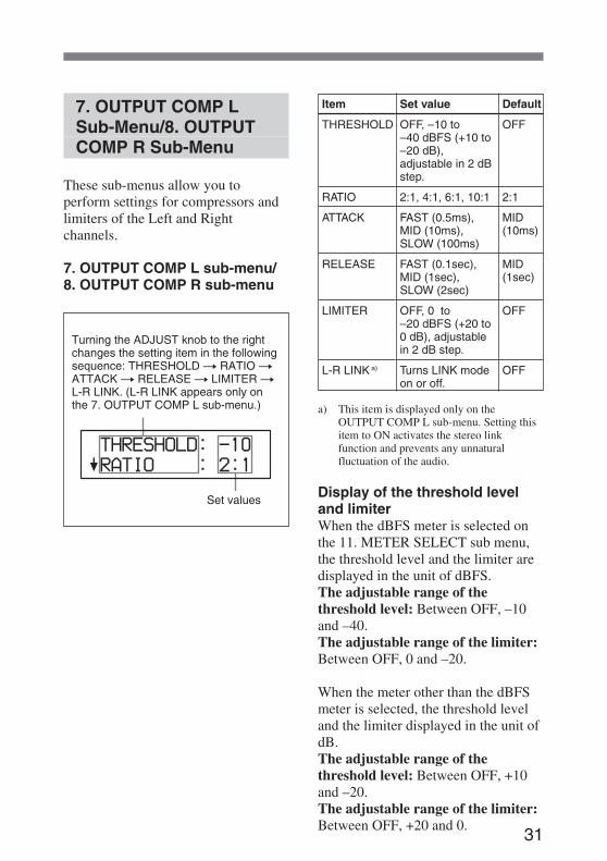
7. OUTPUT COMP LSub-Menu/8. OUTPUTCOMP R Sub-Menu
These sub-menus allow you toperform settings for compressors andlimiters of the Left and Rightchannels.
7. OUTPUT COMP L sub-menu/8. OUTPUT COMP R sub-menu
Turning the ADJUST knob to the rightchanges the setting item in the followingsequence: THRESHOLD t RATIO tATTACK t RELEASE t LIMITER tL-R LINK. (L-R LINK appears only onthe 7. OUTPUT COMP L sub-menu.)
Set values
a) This item is displayed only on theOUTPUT COMP L sub-menu. Setting thisitem to ON activates the stereo linkfunction and prevents any unnaturalfluctuation of the audio.
Display of the threshold leveland limiterWhen the dBFS meter is selected onthe 11. METER SELECT sub menu,the threshold level and the limiter aredisplayed in the unit of dBFS.The adjustable range of thethreshold level: Between OFF, –10and –40.The adjustable range of the limiter:Between OFF, 0 and –20.
When the meter other than the dBFSmeter is selected, the threshold leveland the limiter displayed in the unit ofdB.The adjustable range of thethreshold level: Between OFF, +10and –20.The adjustable range of the limiter:Between OFF, +20 and 0.
Default
OFF
2:1
MID(10ms)
MID(1sec)
OFF
OFF
Item
THRESHOLD
RATIO
ATTACK
RELEASE
LIMITER
L-R LINK a)
Set value
OFF, –10 to–40 dBFS (+10 to–20 dB),adjustable in 2 dBstep.
2:1, 4:1, 6:1, 10:1
FAST (0.5ms),MID (10ms),SLOW (100ms)
FAST (0.1sec),MID (1sec),SLOW (2sec)
OFF, 0 to–20 dBFS (+20 to0 dB), adjustablein 2 dB step.
Turns LINK modeon or off.
32
Settings from the Setup Menu
Note
When L-R LINK is set to ON, youcannot work on the 8. OUTPUTCOMP R sub-menu. If you select the8. OUTPUT COMP R sub-menu andpress the ADJUST knob, thefollowing message appears.
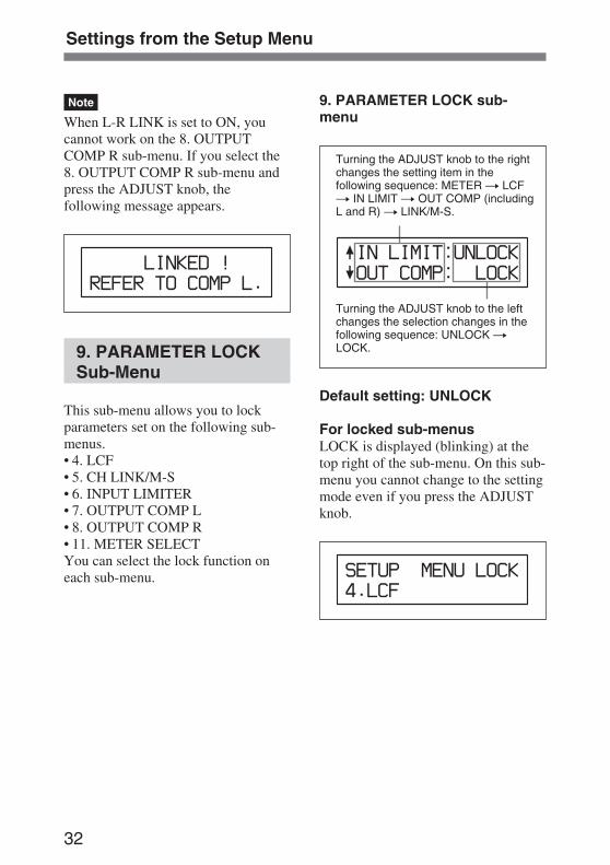
9. PARAMETER LOCKSub-Menu
This sub-menu allows you to lockparameters set on the following sub-menus.• 4. LCF• 5. CH LINK/M-S• 6. INPUT LIMITER• 7. OUTPUT COMP L• 8. OUTPUT COMP R• 11. METER SELECTYou can select the lock function oneach sub-menu.
9. PARAMETER LOCK sub-menu
Turning the ADJUST knob to the rightchanges the setting item in thefollowing sequence: METER t LCFt IN LIMIT t OUT COMP (includingL and R) t LINK/M-S.
Turning the ADJUST knob to the leftchanges the selection changes in thefollowing sequence: UNLOCK tLOCK.
Default setting: UNLOCK
For locked sub-menusLOCK is displayed (blinking) at thetop right of the sub-menu. On this sub-menu you cannot change to the settingmode even if you press the ADJUSTknob.

33
10. PANEL LOCK Sub-Menu
When the FUNCTION switch is set toLOCK, all of or some of the switchesand controls on the front panel arelocked and you cannot operate them.This sub-menu allows you to decidewhich switches and controls should belocked, from among the input levelcontrol, PAN control, LCF switch, L/R MASTER output level control,LINK/M-S switch, and MASTERLINK control.
10. PANEL LOCK sub-menu
Turning the ADJUST knob to the rightchanges the setting item in the followingsequence: IN VOL t PAN t LCF tIN LINK t OUT VOL t OUT LINK.
Turning the ADJUST knob to the rightchanges the selection in the followingsequence: LOCK t UNLOCK.
Default setting: LOCK
11. METER SELECTSub-Menu
This sub-menu allows you to selectthe level meter to be displayed on theLCD from among 6 types of meter,VU, PPM1, PPM2, PPM3, PPM4 anddBFS.The dBFS meter is the default.When you change the type of meterdisplayed using this sub-menu, youshould replace the meter scale sheetwith the one corresponding to the newmeter.For detailed information on thesupplied meter scale sheets, see“Replacing a Meter Scale Sheet” onpage 42.
11. METER SELECT sub-menu
Turning the ADJUST knob to the rightchanges the selection in the followingsequence: VU t PPM1 t PPM2 tPPM3 t PPM4 t dBFS.
The type of the meter currently beingdisplayed is surrounded by parenthesis.
Note
The following table shows therelationship between the meterdisplayed on the LCD and the metertype.
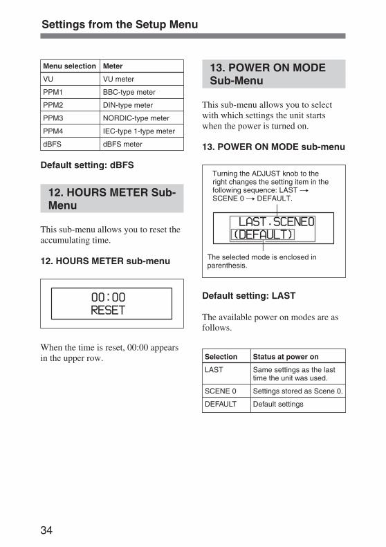
34
Menu selection Meter
VU VU meter
PPM1 BBC-type meter
PPM2 DIN-type meter
PPM3 NORDIC-type meter
PPM4 IEC-type 1-type meter
dBFS dBFS meter
Default setting: dBFS
12. HOURS METER Sub-Menu
This sub-menu allows you to reset theaccumulating time.
12. HOURS METER sub-menu
When the time is reset, 00:00 appearsin the upper row.
13. POWER ON MODESub-Menu
This sub-menu allows you to selectwith which settings the unit startswhen the power is turned on.
13. POWER ON MODE sub-menu
Turning the ADJUST knob to theright changes the setting item in thefollowing sequence: LAST tSCENE 0 t DEFAULT.
The selected mode is enclosed inparenthesis.
Default setting: LAST
The available power on modes are asfollows.
Selection
LAST
SCENE 0
DEFAULT
Status at power on
Same settings as the lasttime the unit was used.
Settings stored as Scene 0.
Default settings
Settings from the Setup Menu
35
Using the Unit to a Camcorder
This section describes how to connectthe unit to a camcorder and how tocheck the connection status.
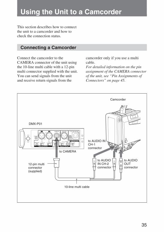
Connecting a Camcorder
Connect the camcorder to theCAMERA connector of the unit usingthe 10-line multi cable with a 12-pinmulti connector supplied with the unit.You can send signals from the unitand receive return signals from the
camcorder only if you use a multicable.For detailed information on the pinassignment of the CAMERA connectorof the unit, see “Pin Assignments ofConnectors” on page 45.
Camcorder
DMX-P01
to AUDIO INCH-1connector
12-pin multiconnector(supplied)
to AUDIOIN CH-2connector
to AUDIOOUTconnector
10-line multi cable
to CAMERA
36
Using the Unit to a Camcorder
Checking the Status ofa Connection
The 3. CAMERA RETURN sub-menuallows you to check formisconnections of lines or otherproblems between the unit and thecamcorder. This function can preventtrouble.To confirm the status of a connection,proceed as follows.
1 Turn on the power of the unit andthe camcorder.
2 Match the reference level of theunit and the camcorder.Set the LEVEL switch on the rightpanel of the unit and the inputlevel select switch on thecamcorder to the same value.When connecting with a +4 dBureference output level:Set the LEVEL switch of the unitto +4 and the input level selectswitch of the camcorder to LINE.When connecting with a –60dBu reference level:Set the LEVEL switch of the unitto –60 and the input level selectswitch of the camcorder to MIC.For detailed information on theswitches of the camcorder, referto the operations manual suppliedwith the camcorder.
3 Send a 1-kHz reference signalusing the SLATE function of theunit, and adjust the output level ofthe unit to the reference valueusing the L/R MASTER volumecontrol.
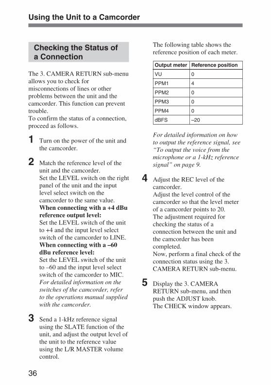
The following table shows thereference position of each meter.
Output meter Reference position
VU 0
PPM1 4
PPM2 0
PPM3 0
PPM4 0
dBFS –20
For detailed information on howto output the reference signal, see“To output the voice from themicrophone or a 1-kHz referencesignal” on page 9.
4 Adjust the REC level of thecamcorder.Adjust the level control of thecamcorder so that the level meterof a camcorder points to 20.The adjustment required forchecking the status of aconnection between the unit andthe camcorder has beencompleted.Now, perform a final check of theconnection status using the 3.CAMERA RETURN sub-menu.
5 Display the 3. CAMERARETURN sub-menu, and thenpush the ADJUST knob.The CHECK window appears.
37
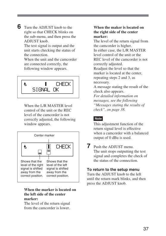
6 Turn the ADJUST knob to theright so that CHECK blinks onthe sub-menu, and then press theADJUST knob.The test signal is output and theunit starts checking the status ofthe connection.When the unit and the camcorderare connected correctly, thefollowing window appears.
When the L/R MASTER levelcontrol of the unit or the REClevel of the camcorder is notcorrectly adjusted, the followingwindow appears.
Center marker
When the marker is located onthe left side of the centermarker:The level of the return signalfrom the camcorder is lower.
Shows that thelevel of the rightsignal is shiftedaway from thecorrect position.
Shows that thelevel of the leftsignal is shiftedaway from thecorrect position.
When the maker is located onthe right side of the centermarker:The level of the return signal fromthe camcorder is higher.In either case, the L/R MASTERlevel control of the unit or theREC level of the camcorder is notcorrectly adjusted.Readjust the level so that themarker is located at the center,repeating steps 2 and 3, asnecessary.A message stating the result of thecheck also appears.For detailed information onmessages, see the following“Messages stating the results ofcheck”, on page 38.
Note
This adjustment function of thereturn signal level is effectivewhen a camcorder with a balancedoutput of 0 dBu is used.
7 Push the ADJUST menu.The unit stops outputting the testsignal and completes the check ofthe status of the connection.
To return to the setup menuTurn the ADJUST knob to the leftuntil the return mark blinks, and thenpress the ADJUST knob.
38
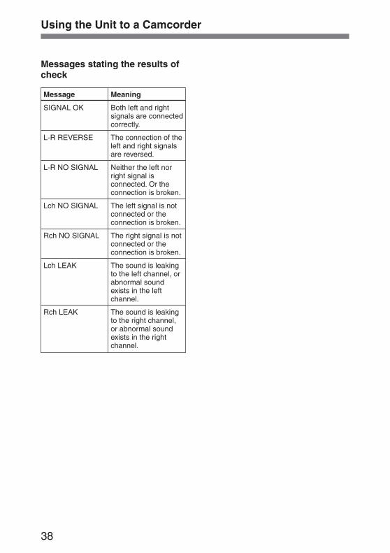
Messages stating the results ofcheck
Message
SIGNAL OK
L-R REVERSE
L-R NO SIGNAL
Lch NO SIGNAL
Rch NO SIGNAL
Lch LEAK
Rch LEAK
Meaning
Both left and rightsignals are connectedcorrectly.
The connection of theleft and right signalsare reversed.
Neither the left norright signal isconnected. Or theconnection is broken.
The left signal is notconnected or theconnection is broken.
The right signal is notconnected or theconnection is broken.
The sound is leakingto the left channel, orabnormal soundexists in the leftchannel.
The sound is leakingto the right channel,or abnormal soundexists in the rightchannel.
Using the Unit to a Camcorder
39
Miscellaneous
Preparing a PowerSupply
The unit can be powered in thefollowing two ways:• Internal batteries
Eight LR6 (size AA) alkalinebatteries can be accommodated in thebattery compartment.
• External batteryA lithium ion battery or nickel metalhydride battery which is connected tothe DC IN 10 - 15 V connector onthe right panel. The unit is equippedwith two types of DC IN 10 - 15 Vconnector, an XLR 4-pin and a DCjack type connector. Use either onedepending on the external batteryyou are using.
Notes
• Do not connect external batteries toboth the 4-pin of the XLR typeconnector and the DC jack typeconnector at the same time.Be sure to connect the externalbattery to either one.Connecting external batteries toboth connectors may cause thedeterioration of the externalbatteries.
• Do not connect the external batteryother than the BP-90 type battery tothe DC jack type connector,because the polarity of the DC jackis different.
When both internal batteries andan external battery are usedWhen the power of the unit is turnedon, the power is supplied from theexternal battery. Since the unit can be
powered by an external battery whilepreserving the life of the internalbatteries, the power supply is switchedfrom internal batteries if the DC cordis disconnected accidentally or theexternal battery is shut downsuddenly.
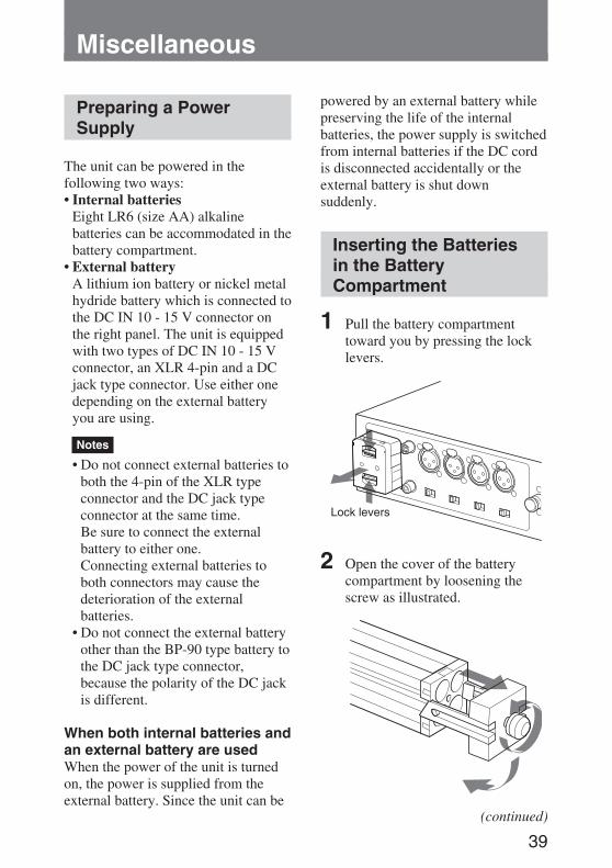
Inserting the Batteriesin the BatteryCompartment
1 Pull the battery compartmenttoward you by pressing the locklevers.
2 Open the cover of the batterycompartment by loosening thescrew as illustrated.
Lock levers
(continued)
40
Miscellaneous
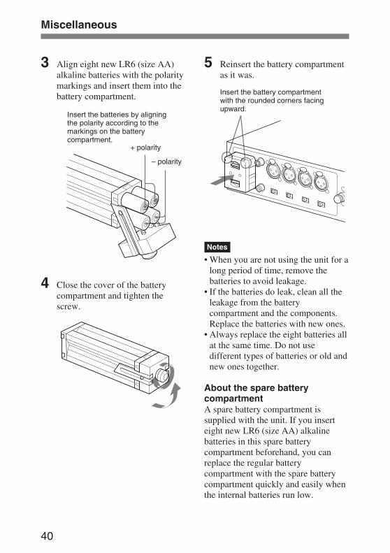
3 Align eight new LR6 (size AA)alkaline batteries with the polaritymarkings and insert them into thebattery compartment.
4 Close the cover of the batterycompartment and tighten thescrew.
Insert the batteries by aligningthe polarity according to themarkings on the batterycompartment.
+ polarity
– polarity
Insert the battery compartmentwith the rounded corners facingupward.
5 Reinsert the battery compartmentas it was.
Notes
• When you are not using the unit for along period of time, remove thebatteries to avoid leakage.
• If the batteries do leak, clean all theleakage from the batterycompartment and the components.Replace the batteries with new ones.
• Always replace the eight batteries allat the same time. Do not usedifferent types of batteries or old andnew ones together.
About the spare batterycompartmentA spare battery compartment issupplied with the unit. If you inserteight new LR6 (size AA) alkalinebatteries in this spare batterycompartment beforehand, you canreplace the regular batterycompartment with the spare batterycompartment quickly and easily whenthe internal batteries run low.
41
Battery life
When the multi meter mode of theLCD is selected, the battery conditionis shown on the LCD.
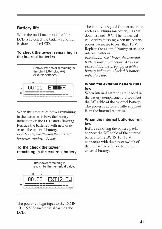
To check the pwoer remaining inthe internal batteries
Shows the power remaining inthe eight LR6 (size AA)alkaline batteries.
When the amount of power remainingin the batteries is low, the batteryindication on the LCD starts flashing.Replace the batteires with new ones,or use the external battery.For details, see “When the internalbatteries run low” below.
To the check the powerremaining in the external battery
The power remaining isshown by the numerical value.
The power voltage input to the DC IN10 - 15 V connector is shown on theLCD.
The battery designed for a camcorder,such as a lithium ion battery, is shutdown around 10 V. The numericalvalue starts flashing when the batterypower decreases to less than 10 V.Replace the external battery or use theinternal batteries.For details, see “When the externalbattery runs low” below. When theexternal battery is equipped with abattery indicator, check this batteryindicator, too.
When the external battery runslowWhen internal batteries are loaded inthe battery compartment, disconnectthe DC cable of the external battery.The power is automatically suppliedfrom the internal batteries.
When the internal batteries runlowBefore removing the battery pack,connect the DC cable of the externalbattery to the DC IN 10 -15 Vconnector with the power switch ofthe unit set to on to switch to theexternal battery.
42
Miscellaneous
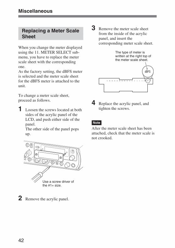
Replacing a Meter ScaleSheet
When you change the meter displayedusing the 11. METER SELECT sub-menu, you have to replace the meterscale sheet with the correspondingone.As the factory setting, the dBFS meteris selected and the meter scale sheetfor the dBFS meter is attached to theunit.
To change a meter scale sheet,proceed as follows.
1 Loosen the screws located at bothsides of the acrylic panel of theLCD, and push either side of thepanel.The other side of the panel popsup.
2 Remove the acrylic panel.
3 Remove the meter scale sheetfrom the inside of the acrylicpanel, and insert thecorresponding meter scale sheet.
The type of meter iswritten at the right top ofthe meter scale sheet.
4 Replace the acrylic panel, andtighten the screws.
Note
After the meter scale sheet has beenattached, check that the meter scale isnot crooked.
Use a screw driver ofthe #1+ size.
43
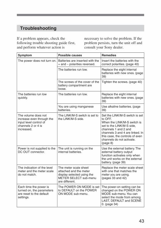
If a problem appears, check thefollowing trouble shooting guide first,and perform whatever action is
Symptom
The power does not turn on.
The batteries run lowquickly.
The volume does notincrease even through theinput level control ofchannels 2 or 4 isincreased.
Power is not supplied to theDC OUT connector.
The indication of the levelmeter and the meter scaledo not match.
Each time the power isturned on, the parametersare reset to the defaultsettings.
Possible causes
Batteries are inserted with the+ and – polarities reversed.
The batteries run low.
The screws of the cover of thebattery compartment areloose.
The batteries run low.
You are using manganesebatteries.
The LINK/M-S switch is set tothe LINK/M-S side.
The unit is running on theinternal batteries.
The meter scale sheetattached and the meterdisplay selected using theMETER SELECT sub-menuare different.
The POWER ON MODE is setto DEFAULT on the POWERON MODE sub-menu.
Remedies
Insert the batteries with thecorrect polarities. (page 40)
Replace the eight internalbatteries with new ones. (page39)
Tighten the screws. (page 40)
Replace the eight internalbatteries with new ones. (page39)
Use alkaline batteries. (page39)
Set the LINK/M-S switch is setto OFF.When the LINK/M-S switch isset to the LINK/M-S side,channels 1 and 2 andchannels 3 and 4 are linked. Inthis case, the controls of evenchannels do not activate.(page 8)
Use the external battery. Theexternal battery outputfunction activates only whenthe unit works on the externalbattery. (page 39)
Replace the meter scale sheetwith one that matches themeter you are using.(pages 33 and 42)
The power-on setting can bechanged on the POWER ONMODE sub-menu. You canselect the mode from amongLAST, DEFAULT and SCENE0. (page 34)
Troubleshooting
necessary to solve the problem. If theproblem persists, turn the unit off andconsult your Sony dealer.
44
Miscellaneous
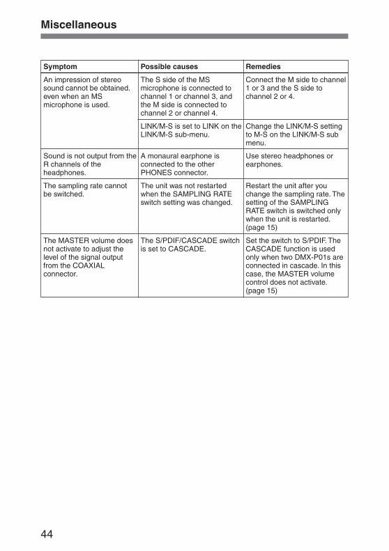
Symptom
An impression of stereosound cannot be obtained.even when an MSmicrophone is used.
Sound is not output from theR channels of theheadphones.
The sampling rate cannotbe switched.
The MASTER volume doesnot activate to adjust thelevel of the signal outputfrom the COAXIALconnector.
Possible causes
The S side of the MSmicrophone is connected tochannel 1 or channel 3, andthe M side is connected tochannel 2 or channel 4.
LINK/M-S is set to LINK on theLINK/M-S sub-menu.
A monaural earphone isconnected to the otherPHONES connector.
The unit was not restartedwhen the SAMPLING RATEswitch setting was changed.
The S/PDIF/CASCADE switchis set to CASCADE.
Remedies
Connect the M side to channel1 or 3 and the S side tochannel 2 or 4.
Change the LINK/M-S settingto M-S on the LINK/M-S submenu.
Use stereo headphones orearphones.
Restart the unit after youchange the sampling rate. Thesetting of the SAMPLINGRATE switch is switched onlywhen the unit is restarted.(page 15)
Set the switch to S/PDIF. TheCASCADE function is usedonly when two DMX-P01s areconnected in cascade. In thiscase, the MASTER volumecontrol does not activate.(page 15)
45
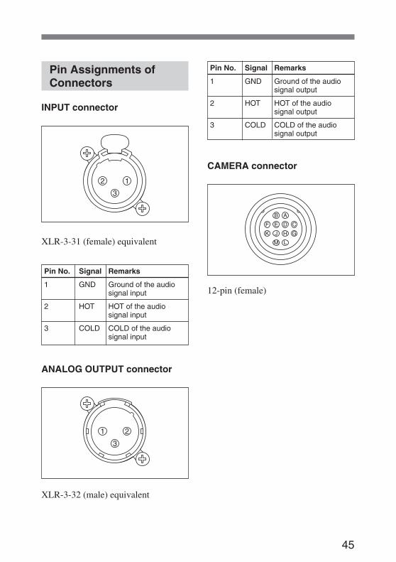
Pin Assignments ofConnectors
INPUT connector
XLR-3-31 (female) equivalent
Pin No. Signal Remarks
1 GND Ground of the audiosignal input
2 HOT HOT of the audiosignal input
3 COLD COLD of the audiosignal input
ANALOG OUTPUT connector
XLR-3-32 (male) equivalent
Pin No. Signal Remarks
1 GND Ground of the audiosignal output
2 HOT HOT of the audiosignal output
3 COLD COLD of the audiosignal output
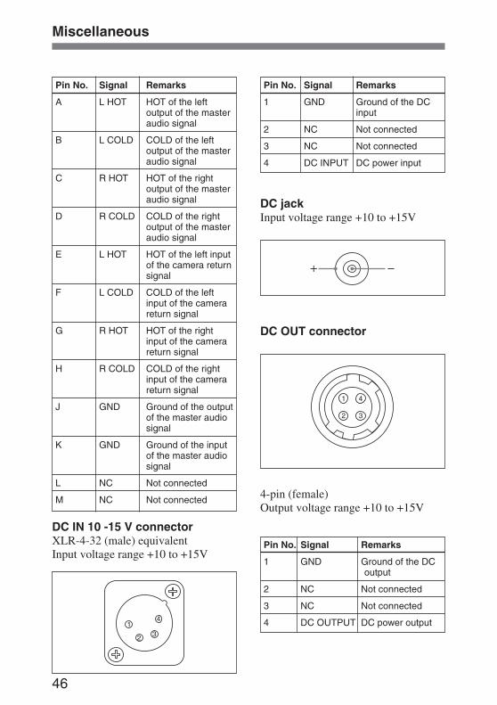
CAMERA connector
12-pin (female)
46
Pin No. Signal Remarks
A L HOT HOT of the leftoutput of the masteraudio signal
B L COLD COLD of the leftoutput of the masteraudio signal
C R HOT HOT of the rightoutput of the masteraudio signal
D R COLD COLD of the rightoutput of the masteraudio signal
E L HOT HOT of the left inputof the camera returnsignal
F L COLD COLD of the leftinput of the camerareturn signal
G R HOT HOT of the rightinput of the camerareturn signal
H R COLD COLD of the rightinput of the camerareturn signal
J GND Ground of the outputof the master audiosignal
K GND Ground of the inputof the master audiosignal
L NC Not connected
M NC Not connected
DC IN 10 -15 V connectorXLR-4-32 (male) equivalentInput voltage range +10 to +15V
Pin No. Signal Remarks
1 GND Ground of the DCinput
2 NC Not connected
3 NC Not connected
4 DC INPUT DC power input
DC jackInput voltage range +10 to +15V
DC OUT connector
4-pin (female)Output voltage range +10 to +15V
Pin No. Signal Remarks
1 GND Ground of the DCoutput
2 NC Not connected
3 NC Not connected
4 DC OUTPUT DC power output
Miscellaneous
47
Specifications
General
Power requirements10 - 15 V DC (at the external
power supply from the DCIN 10 - 15 V connector)
Maximum power consumption1400 mA or less (at the
external power supply fromthe DC IN 10 - 15 Vconnector)
Operating temperature0°C to 45°C
(32°F to 113°F)Storage temperature
–20°C to 60°C(–4°F to 140°F)
Continuous operation timeApprox. 5 hours
at the follwoing condition:Power supply; 8 LR6/AA-size Sony alkalinebatteriesSampling frequency;48 kHz,Temparature; 25°C( 77°F),LCD Light; offDC +48 V; off
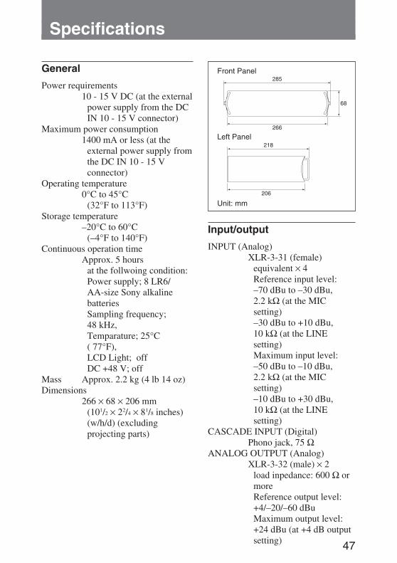
Mass Approx. 2.2 kg (4 lb 14 oz)Dimensions
266 × 68 × 206 mm(101/2 × 22/4 × 81/8 inches)(w/h/d) (excludingprojecting parts)
Input/output
INPUT (Analog)XLR-3-31 (female)
equivalent × 4Reference input level:–70 dBu to –30 dBu,2.2 kΩ (at the MICsetting)–30 dBu to +10 dBu,10 kΩ (at the LINEsetting)Maximum input level:–50 dBu to –10 dBu,2.2 kΩ (at the MICsetting)–10 dBu to +30 dBu,10 kΩ (at the LINEsetting)
CASCADE INPUT (Digital)Phono jack, 75 Ω
ANALOG OUTPUT (Analog)XLR-3-32 (male) × 2
load inpedance: 600 Ω ormoreReference output level:+4/–20/–60 dBuMaximum output level:+24 dBu (at +4 dB outputsetting)
Front Panel
Left Panel
Unit: mm
48
AES/EBU (Digital)XLR-3-32 (male)
equivalent, 110 ΩS/PDIF / CASCADE (Digital)
Phono jack, 75 ΩPHONES (Analog)
Stereo phone jack × 13.5 mm TRS jack × 1,
load impedance:32 Ω or more,300 mW or more (at a32 Ω load)
TAPE OUT (Analog)3.5 mm TRS jack, load
impedance: 10 kΩ ormore,Reference output level:–10 dBuMaximum output level:+ 10 dBu
CAMERA12-PIN
Reference input level:0 dBuReference output level:+4/–20/–60 dBu
DC OUT4-pin (female),output
voltage range:+10 to +15 V
DC IN 10 - 15 VXLR-4-32 (male)
equivalent,input voltage range:+10 to +15 V
DC jack, input voltagerange: +10 to +15 V
Audio characteristics
Frequency response20 Hz to 20 kHz, 0.5/–1 dB
(at a 48-kHz samplingfrequency)
20 Hz to 40 kHz, 0.5/–3 dB(at a 96-kHz samplingfrequency)
Noise level (E.I.N)–130 dBu or less
(A-weighted, mic input,150 Ω terminated, typical)
T.H.D 0.05 % or less (at 1 kHz,+4 dBu)
Maximum output level+24 dBu, load impedance
10 kΩCrosstalk –90 dB or less (at 1 kHz)
Supplied accessories
Meter scale sheet (5)Spare battery compartment (1)Feet (4) a)
12-pin multi connector (1)Clamp filter (2)Band (2)Operating Instructions (1)CD-ROM (Operating Instructions pdf
files) (1)
a) When you use the unit on a desk, it mayslide around easily. To prevent it frommoving, it is recommended that you attachthe feet supplied to the bottom of the unit.
Design and specifications are subjectto change without notice.
Specifications
49
OF
F A
B
OF
F A
B
OF
F A
B
OF
F A
B
+48V
CH
1A
ES
/EB
U
OU
TP
UT
L
OU
TP
UT
R
CA
ME
RA
CO
AX
IAL
PH
ON
ES
PH
ON
ES
DC
INX
LR Type
DC
OU
T
DC
IN JA
CK
8 x LR6
(SIZ
E A
A)
TAP
E O
UT
-10dBu
HA
ATT
AD
CLC
F
24bit96k/48kH
z
LEV
EL
ME
TE
RCH
AN
NE
LV
OL
CH
AN
NE
LV
OL
PAN
INP
UT
LIMIT
ER
LINK
/M-S
Trim+
10 to -30dBu
-30 to -70dBu
LIM
LIM
PE
AK
LED
OU
TP
UT
CO
MP
/LIM
ITE
R
S/P
DIF
CA
SC
AD
E
MA
ST
ER
VO
LS
TER
EO
/MO
NO
1kHz
OF
FM
IC
+48V
CH
2H
AAT
TA
DC
LCF
CH
AN
NE
LV
OL
PAN
INP
UT
LIMIT
ER
Trim+
10 to -30dBu
-30 to -70dBu
LIM
M S
+48V
CH
3H
AAT
TA
DC
LCF
24bit96k/48kH
z
LEV
EL
ME
TE
R
PAN
INP
UT
LIMIT
ER
LINK
/M-S
Trim+
10 to -30dBu
-30 to -70dBu
LIM
+48V
CH
4
CA
SC
AD
EIN
HA
ATT96kH
z
INT
SY
NC
/ DI S
YN
CO
SC
1kHz
SLAT
EM
ICS
AM
PLIN
G R
ATE
SE
LEC
T
48kHz
AD
CLC
F
CH
AN
NE
LV
OL
PAN
INP
UT
LIMIT
ER
Trim+
10 to -30dBu
-30 to -70dBu
LIM
M S
DI
AG
C/A
DC
LIM
DO
DODA
C
DA
C
CP
U
ATT
ATT
+4/-20/-60dB
u
HE
AD
PH
ON
ES
ELE
CT
/M-S
DE
CO
RD
HE
AD
PH
ON
EA
MP
HE
ATE
R
PO
WE
R S
W
INT
/EX
TS
W
24bit96k/48kH
z
24bit96k/48kH
z
LEV
EL
ME
TE
R
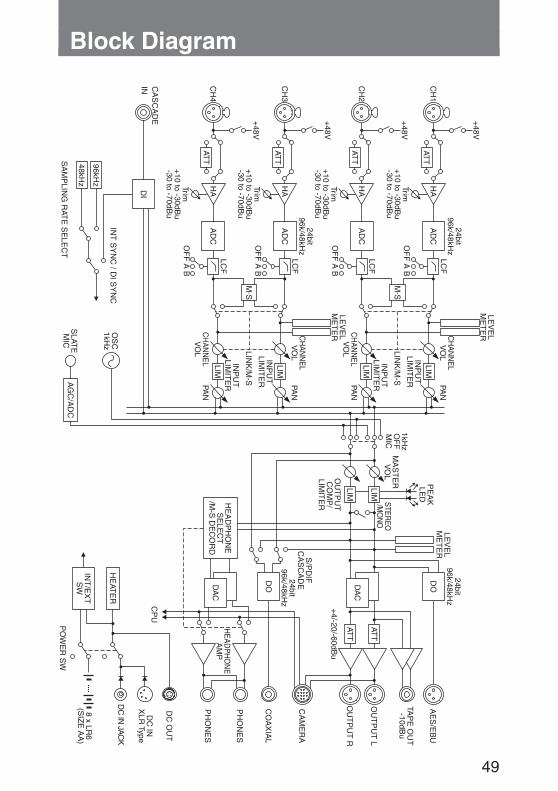
Block Diagram

Sony Corporation

![[SPECO] Catalog - Concrete Batching Plant · 2018. 11. 14. · Concrete batching plant Silo Top Type Portable Batching Plant Ribbon & Twin Mixer Portable Shuttle Conveyor Portable](https://img.pdfslide.us/doc/110x75/6134471cdfd10f4dd73ba0cc/speco-catalog-concrete-batching-plant-2018-11-14-concrete-batching-plant.jpg)