Embed Size (px)
Citation preview
Digital PECVD Machine Design and Construction
Zlatan Ceric
William Edwards
Timothy Gurtler
David Ogden
Quan Tran
Date:12/10/2010

Project Overview
Contracted by Nanotechnology Research Center Converted existing RIE to PECVD machine Automation of process eliminates the need for
constant human monitoring Cost of Hardware: $35,000 Built base model for NRC modification
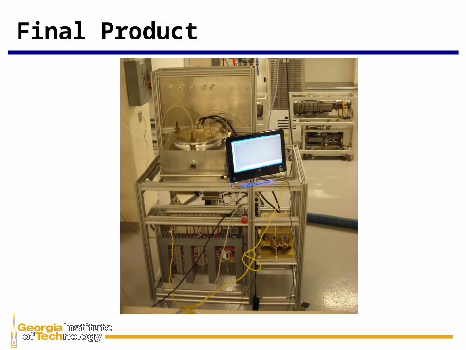
Final Product
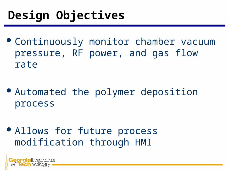
Design Objectives
Continuously monitor chamber vacuum pressure, RF power, and gas flow rate
Automated the polymer deposition process
Allows for future process modification through HMI
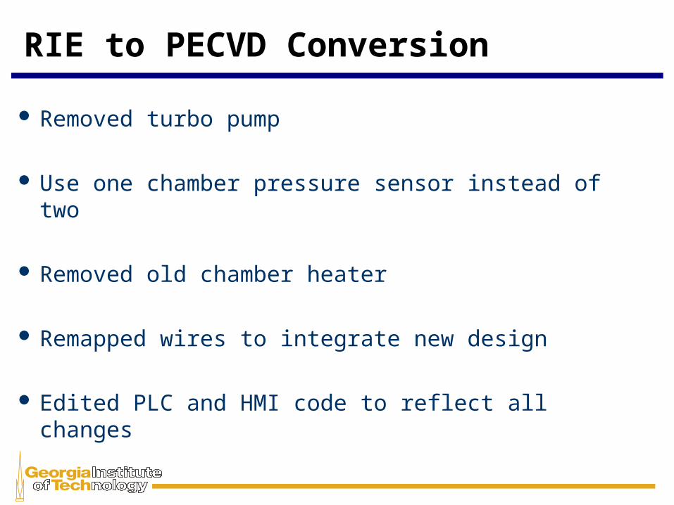
RIE to PECVD Conversion
Removed turbo pump
Use one chamber pressure sensor instead of two
Removed old chamber heater
Remapped wires to integrate new design
Edited PLC and HMI code to reflect all changes
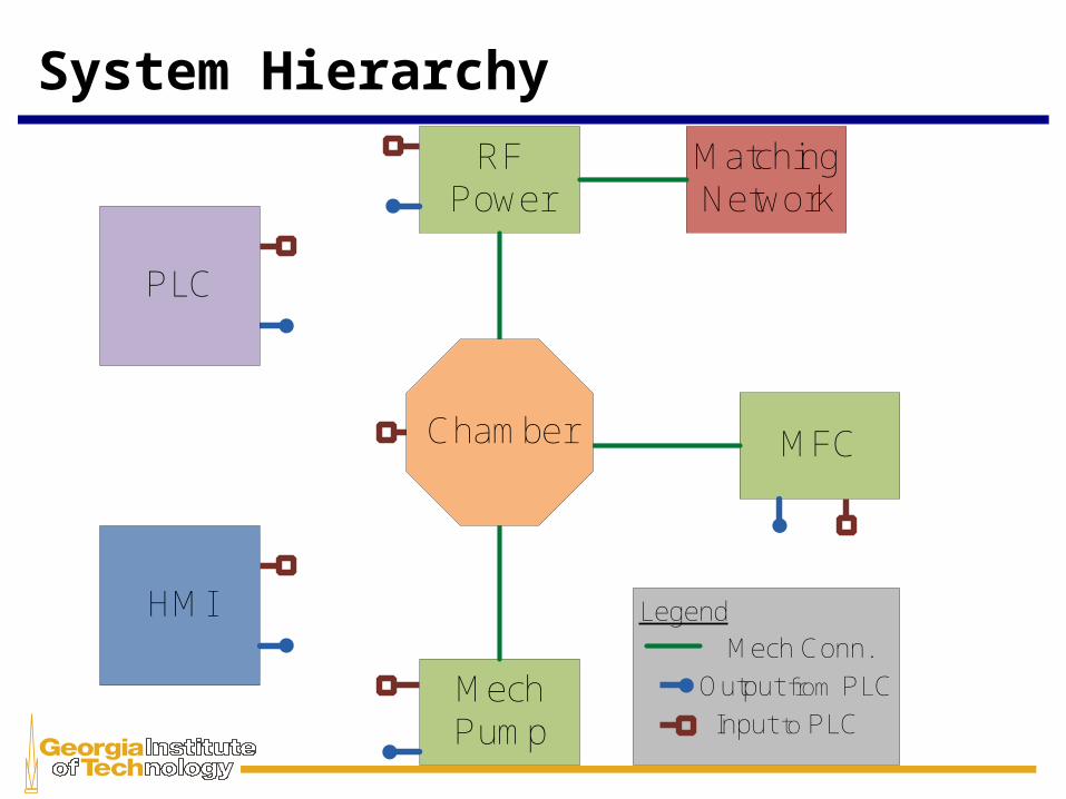
System Hierarchy
HMI
RF Power
Mech Pump
MFC
Matching Network
Legend
Input to PLC
Output from PLC
Mech Conn.
PLC
Chamber
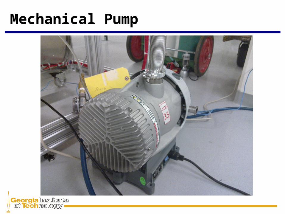
Mechanical Pump
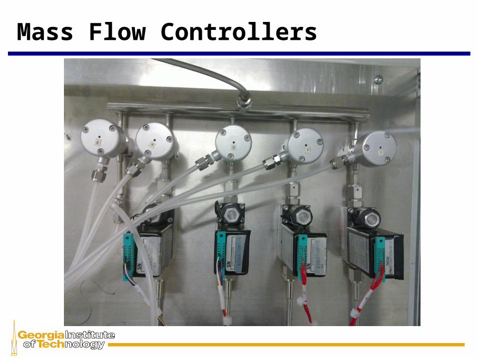
Mass Flow Controllers
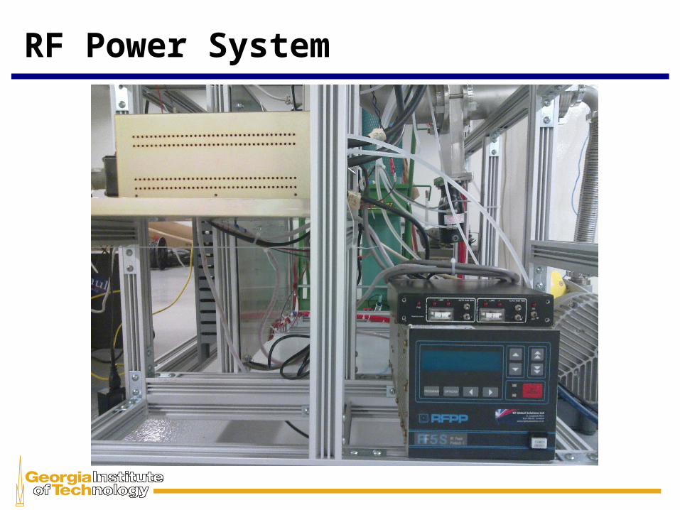
RF Power System

Chassis Construction
Gator Jaw is the material used to build the stand
It is customizable and easily changed if needed
Plates can be mounted to the frame to provided a surface for components to mount
Component Mounting
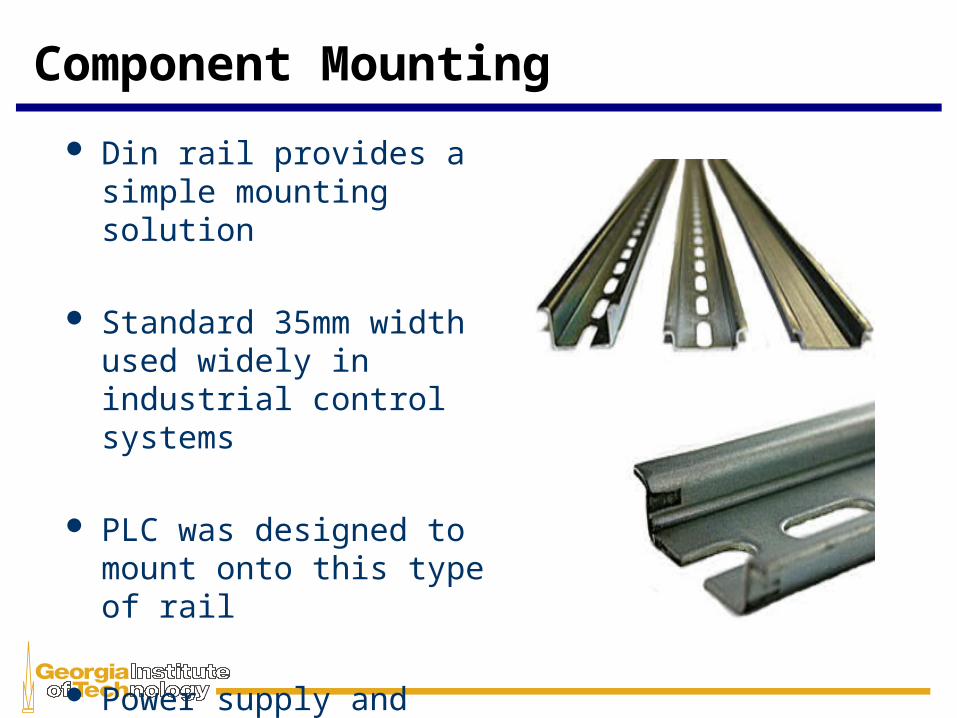
Din rail provides a simple mounting solution
Standard 35mm width used widely in industrial control systems
PLC was designed to mount onto this type of rail
Power supply and terminal blocks also mount to it
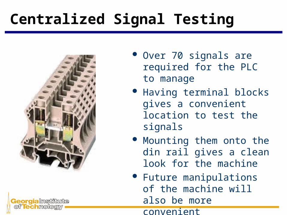
Centralized Signal Testing
Over 70 signals are required for the PLC to manage
Having terminal blocks gives a convenient location to test the signals
Mounting them onto the din rail gives a clean look for the machine
Future manipulations of the machine will also be more convenient
Testing the Machine
Wire continuity was first check to ensure each component was properly connected
Each Input into the PLC was forced on to ensure each component was working properly
Feedback was compared between components and HMI Display
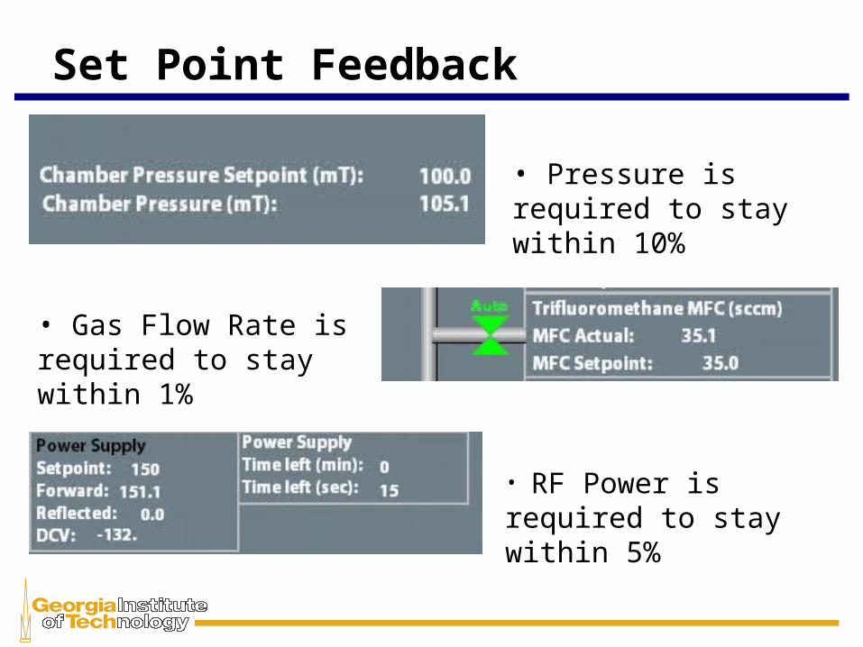
Set Point Feedback
• Pressure is required to stay within 10%
• Gas Flow Rate is required to stay within 1%
• RF Power is required to stay within 5%
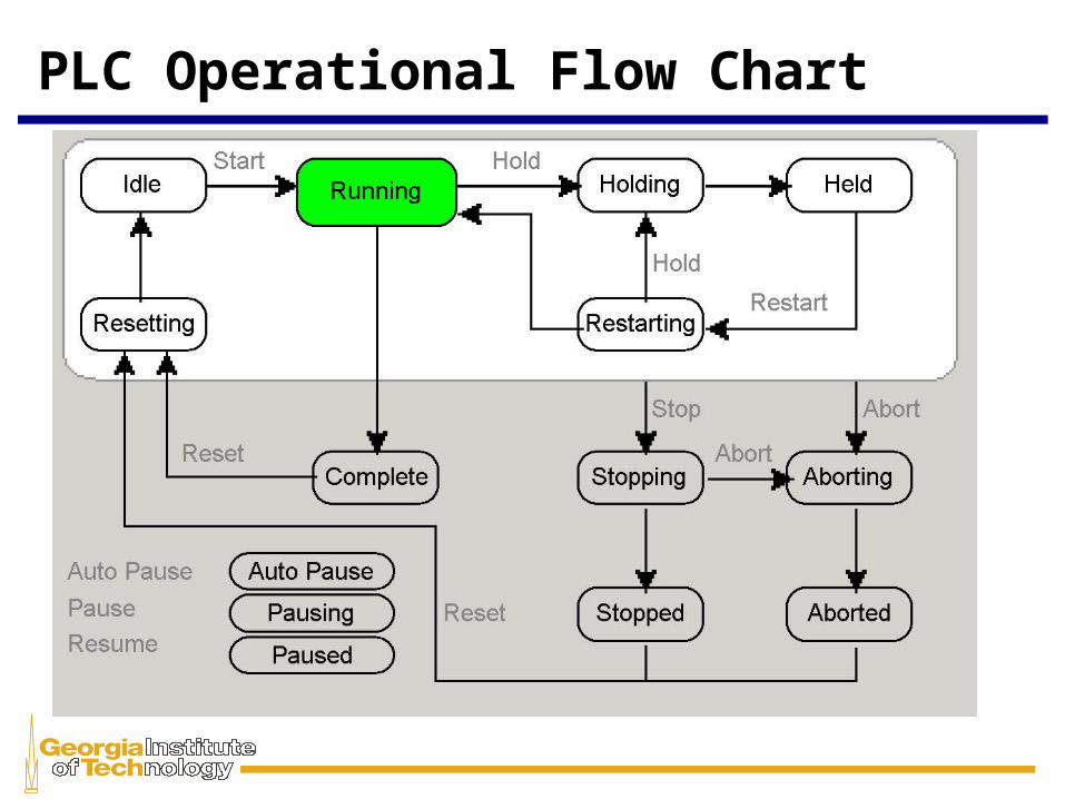
PLC Operational Flow Chart
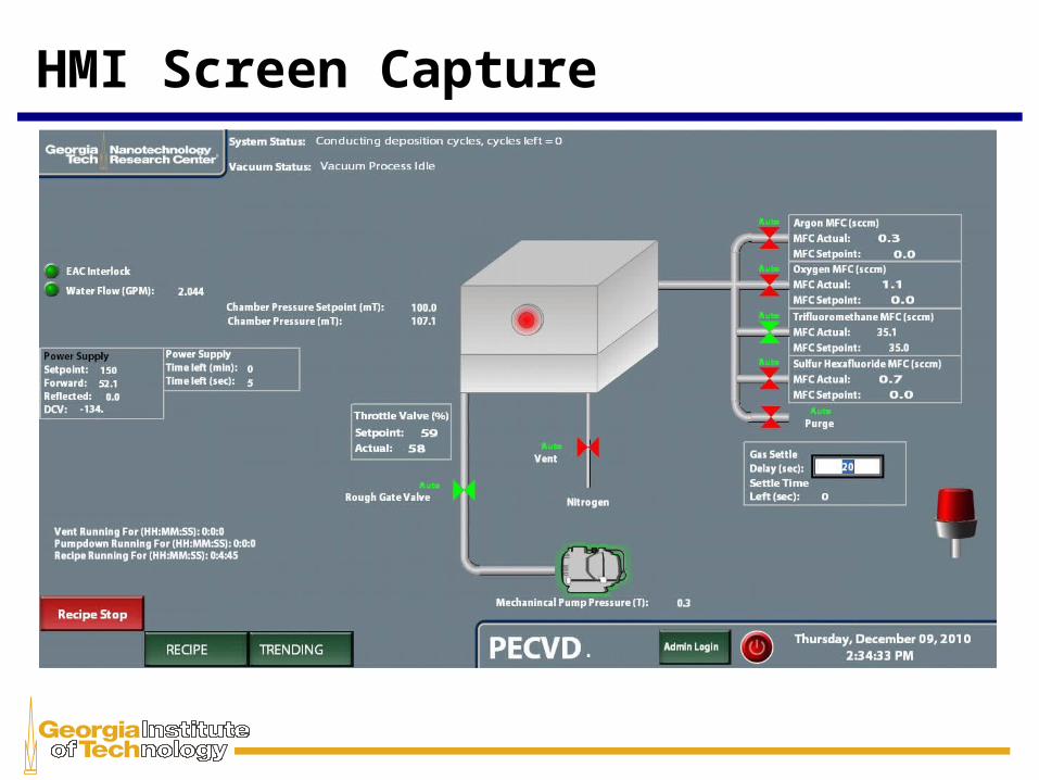
HMI Screen Capture
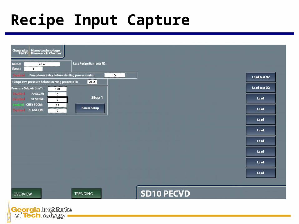
Recipe Input Capture
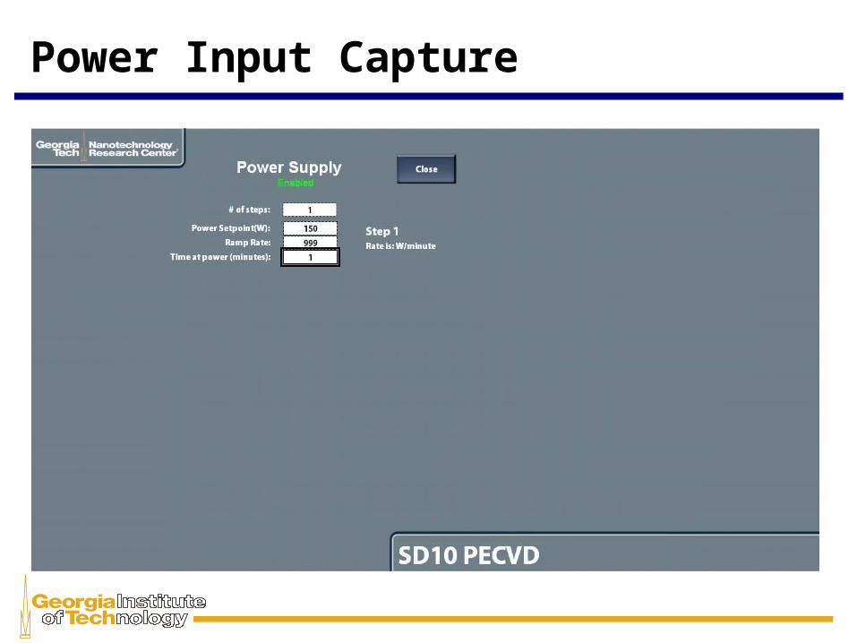
Power Input Capture

Coding Challenges Working with new programs and languages:
– RSLogix5000 with Ladder Logic– FactoryTalk View Studio
Interfacing with analog, digital, and serial connections
Inability to test and debug software before machine was fully assembled
Not able to implement “Trending” function due to time constraints
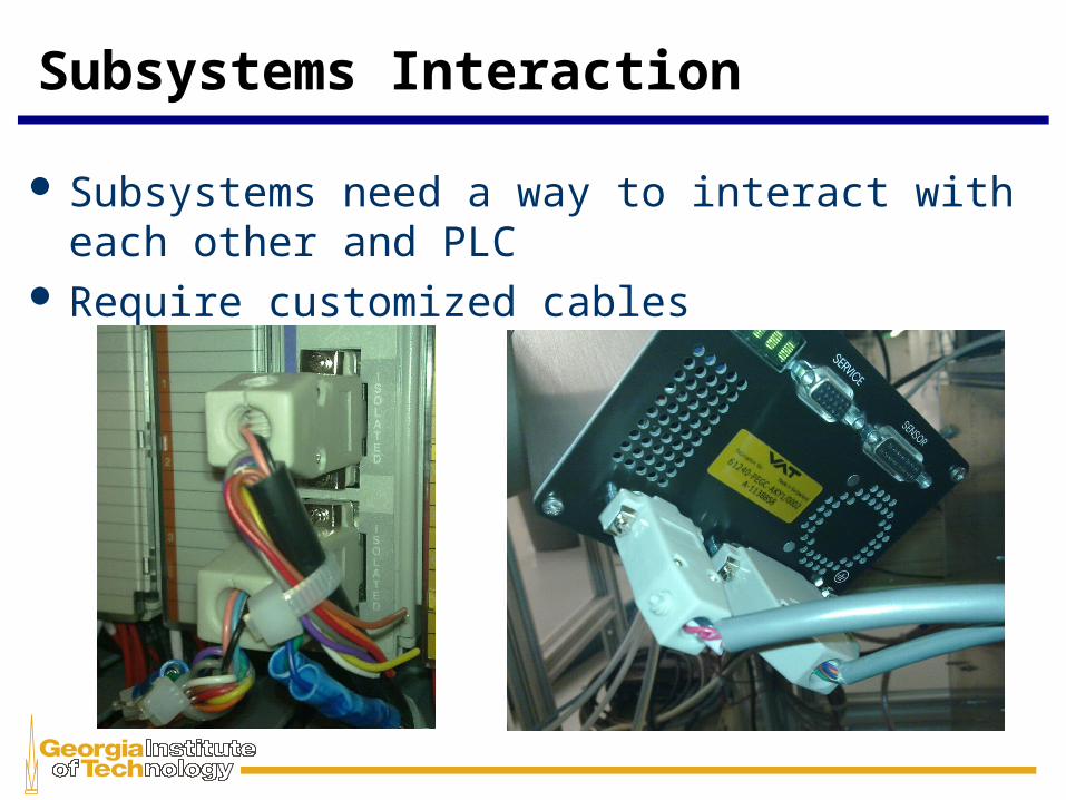
Subsystems Interaction
Subsystems need a way to interact with each other and PLC
Require customized cables
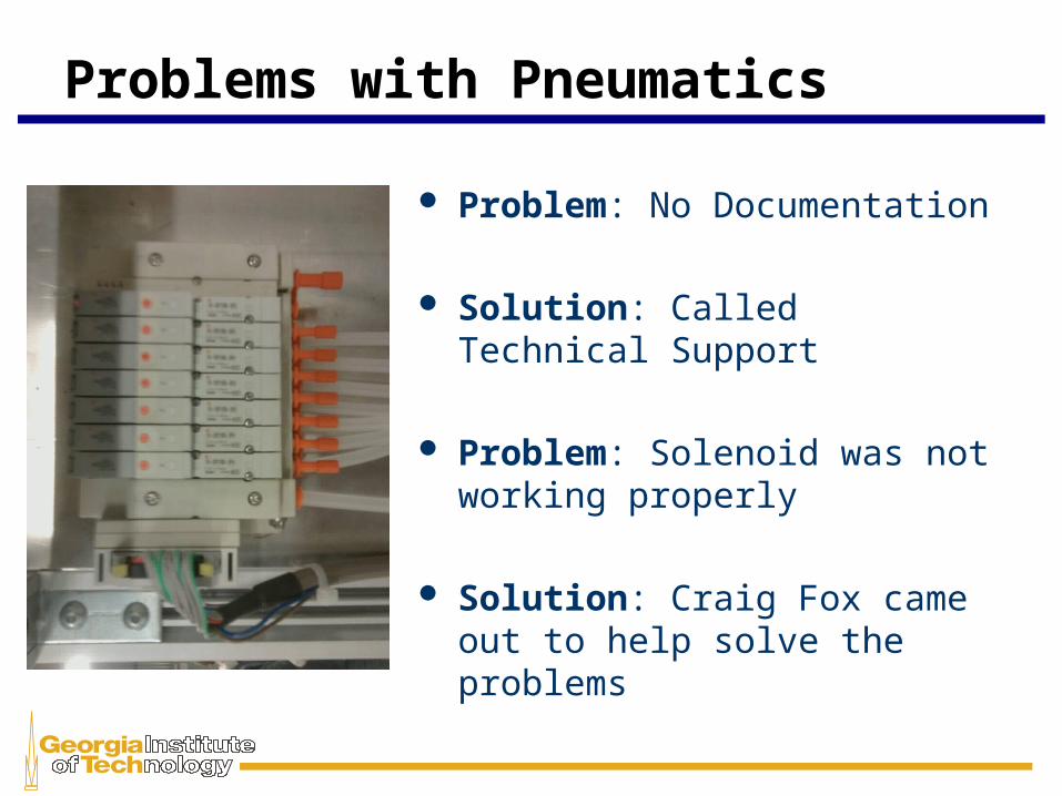
Problems with Pneumatics
Problem: No Documentation
Solution: Called Technical Support
Problem: Solenoid was not working properly
Solution: Craig Fox came out to
help solve the problems
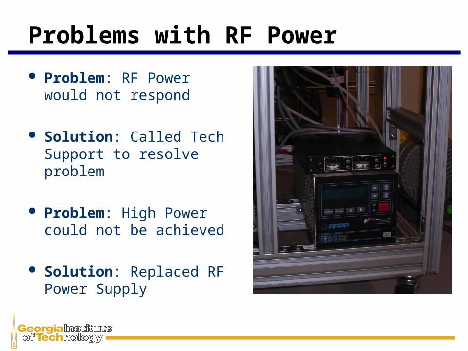
Problems with RF Power
Problem: RF Power would not respond
Solution: Called Tech Support to resolve problem
Problem: High Power could not be achieved
Solution: Replaced RF Power Supply
Budget and Cost
Project is exclusively design for Ga Tech NRC and cannot be used for mass production
Parts were donated, salvaged, and funded by:– Ga Tech NRC– Rockwell Automation
A conservative estimate cost of $135,000 including hardware and labor/testing for completed project
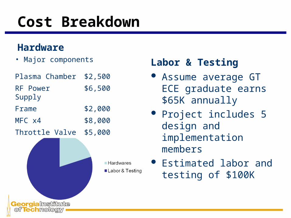
Cost Breakdown
Labor & Testing Assume average GT ECE
graduate earns $65K annually
Project includes 5 design and implementation members
Estimated labor and testing of $100K
Hardware
Plasma Chamber $2,500
RF Power Supply $6,500
Frame $2,000
MFC x4 $8,000
Throttle Valve $5,000
• Major components
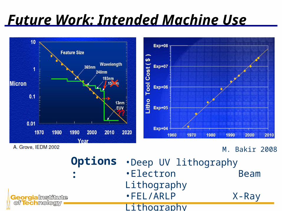
Future Work: Intended Machine Use
M. Bakir 2008
Options: •Deep UV lithography•Electron Beam Lithography•FEL/ARLP X-Ray Lithography•Nano Imprint Lithography

Topographic negative of structure will will be constructed with electron beam lithographyOrganic Gas will deposit non stick polymer on moldMold will be used as press to relief desired structureAntistick coating will have to be reapplied after several uses (~3)
Future Work: Additional Machine Use
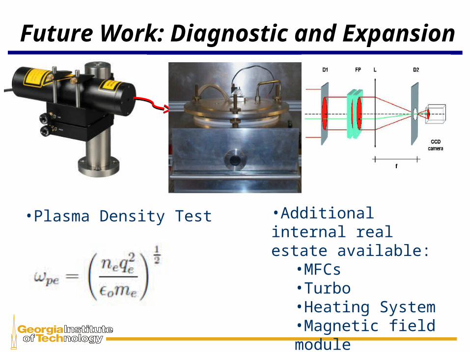
Future Work: Diagnostic and Expansion
•Plasma Density Test •Additional internal real estate available:
•MFCs•Turbo•Heating System•Magnetic field module
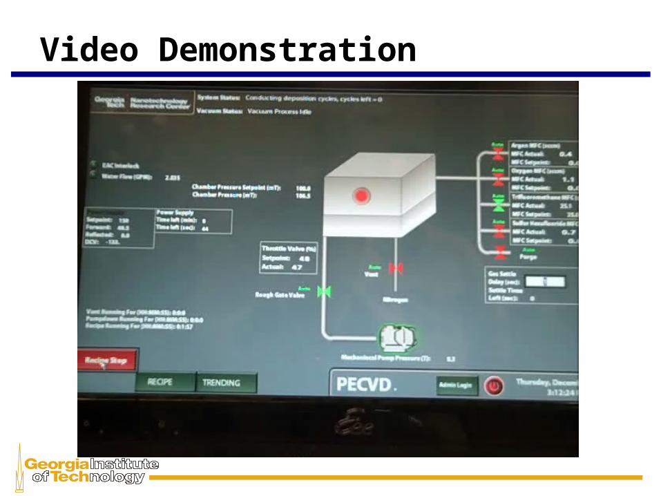
Video Demonstration

Questions or Comments?