Embed Size (px)
Citation preview
Cloud Computing Page 1
DIGITAL NOTES ON
CLOUD COMPUTING B.TECH III YR / II SEM
(2017-18)
DEPARTMENT OF INFORMATION TECHNOLOGY
MALLA REDDY COLLEGE OF ENGINEERING & TECHNOLOGY
(Autonomous Institution – UGC, Govt. of India) Recognized under 2(f) and 12 (B) of UGC ACT 1956
(Affiliated to JNTUH, Hyderabad, Approved by AICTE - Accredited by NBA & NAAC – ‘A’ Grade - ISO 9001:2015 Certified)
Maisammaguda, Dhulapally (Post Via. Hakimpet), Secunderabad – 500100, Telangana State, India
Cloud Computing Page 2
MALLA REDDY COLLEGE OF ENGINEERING & TECHNOLOGY Department of Information Technology
III Year B.Tech IT – II Sem L T /P/D C
4 / - / - 4 (R15A0529) CLOUD COMPUTING
Objectives:
• To understand the various distributed system models and evolving computing paradigms
• To gain knowledge in virtualization of computer resources
• To realize the reasons for migrating into cloud
• To introduce the various levels of services that can be achieved by a cloud.
• To describe the security aspects in cloud and the services offered by a cloud.
UNIT- Systems Modeling: Distributed System Models and Enabling Technologies- Scalable Computing over the Internet- System Models for Distributed and Cloud Computing- Software Environments for Distributed Systems and Clouds-- Performance, Security, and Energy Efficiency
Computer Clusters for Scalable Parallel Computing: Clustering- Clustering for Massive Parallelism-Computer Clusters and MPP Architectures-Design Principles of Computer Clusters-Cluster Job and Resource Management.
UNIT- II
Virtualization: Virtual Machines and Virtualization of Clusters and Data Centers- Implementation Levels of Virtualization -Virtualization Structures/Tools and Mechanisms-Virtualization of CPU, Memory, and I/O Devices-Virtual Clusters and Resource Management-Virtualization for Data-Center Automation
UNIT- III
Foundations: Introduction to Cloud Computing- Migrating into a Cloud-The Enterprise Cloud Computing Paradigm.
UNIT- IV
Infrastructure as a Service (IAAS)& Platform (PAAS):Virtual machines provisioning and Migration services-On the Management of Virtual machines for Cloud Infrastructures-Aneka—Integration of Private and Public Clouds
UNIT- V
Software as a Service( SAAS)&Data Security in the Cloud:
Google App Engine – Centralizing Email Communications- Collaborating via Web-Based Communication Tools-An Introduction to the idea of Data Security- The Current State of Data Security in the Cloud- Cloud Computing and Data Security Risk- Cloud Computing and Identity.
TEXT BOOKS:
1. Distributed and Cloud Computing, Kaittwang Geoffrey C.Fox and Jack J Dongrra, Elsevier India 2012.
Cloud Computing Page 3
2.Mastering Cloud Computing- Raj Kumar Buyya, Christian Vecchiola and S.TanuraiSelvi, TMH, 2012.
3. Michael Miller, Cloud Computing: Web-Based Applications That Change the Way You Work and
Collaborate Online, Que Publishing, August 2008.
Reference Books:
1. Cloud Computing : A Practical Approach, Anthony T.Velte, Toby J.Velte, Robert Elsenpeter, Tata McGraw Hill, rp2011.
2. Enterprise Cloud Computing, Gautam Shroff, Cambridge University Press, 2010.
3. Cloud Computing: Implementation, Management and Security, John W.Rittinghouse, James F.Ransome, CRC Press, rp2012.
4. Cloud Application Architectures: Building Applications and Infrastructure in the Cloud, George Reese, O’reilly, SPD, rp2011.
5. Cloud Security and Privacy: An Enterprise Perspective on Risks and Compliance, Tim Mather, Subra Kumaraswamy, Shahed Latif, O’Reilly, SPD, rp2011.
Outcomes:
• To distinguish the different models and computing paradigms.
• To explain the levels of virtualization and resources virtulaization
• To analyze the reasons for migrating into cloud
• To effectively use the cloud services in terms of infrastructure and operating platforms.
• To apply the services in the cloud for real world scenarios
Cloud Computing Page 4
INDEX
S.NO Title Page No
1 Computing Paradigm & Degrees of Parallelism 5
2 The Internet of Things (IoT) & Cyber-Physical Systems 7
3 System Models For Distributed And Cloud Computing 7
4 Service-Oriented Architecture (SOA) 9
5 Performance Metrics & Energy Efficiency in Distributed Computing 10
6 Clustering for Massive Parallelism 14
7 Basic Cluster Architecture 15
8 Levels of Virtualization Implementation 29
9 VMM Design Requirements and Providers 30
10 Xen Architecture 32
11 Full virtualization- CPU Memory-I/O Virtualization 32
12 Cloud OS for Virtualized Data Centers 36
13 Introduction to Cloud Computing 37
14 Introduction – Migration into cloud 40
15 Challenges in the Cloud 43
16 Introduction to IAAS 44
17 OVF (Open Virtualization Format) 47
18 Live Migration Effect 50
19 Aneka 52
20 SaaS 53
21 Integration Products And Platforms 53
22 Google App Engine 54
23 Centralizing Email Communications 55
24 Collaborating via Web-Based Communication Tools 56
25 An Introduction to the idea of Data Security 57
26 The Current State of Data Security in the Cloud 58
27 Cloud Computing and Identity 59
28 Cloud Computing and Data Security Risk 60
Cloud Computing Page 5
UNIT -1
Scalable Computing over the Internet
High-Throughput Computing-HTC
HTC paradigm pays more attention to high-flux computing. The main application for high-flux
computing is in Internet searches and web services by millions or more users simultaneously.
The performance measures high throughput or the number of tasks completed per unit of time.
HTC technology needs to improve batch processing speed, and also address the acute problems
of cost, energy savings, security, and reliability at many data and enterprise computing centers
Computing Paradigm Distinctions
• Centralized computing
o This is a computing paradigm by which all computer resources are centralized in one
physical system.
o All resources (processors, memory, and storage) are fully shared and tightly coupled within
one integrated OS.
o Many data centers and supercomputers are centralized systems, but they are used in parallel,
distributed, and cloud computing applications.
• Parallel computing
• In parallel computing, all processors are either tightly coupled with centralized shared
memory or loosely coupled with distributed memory
• . Interprocessor communication is accomplished through shared memory or via message
passing.
• A computer system capable of parallel computing is commonly known as a parallel computer
• Programs running in a parallel computer are called parallel programs. The process of writing
parallel programs is often referred to as parallel programming
• Distributed computing
• A distributed system consists of multiple autonomous computers, each having its own
private memory, communicating through a computer network.
• Information exchange in a distributed system is accomplished through message passing.
• A computer program that runs in a distributed system is known as a distributed program.
• The process of writing distributed programs is referred to as distributed programming.
• Distributed computing system uses multiple computers to solve large-scale problems over
the Internet using a centralized computer to solve computational problems.
• Cloud computing
• An Internet cloud of resources can be either a centralized or a distributed computing system.
The cloud applies parallel or distributed computing, or both.
• Clouds can be built with physical or virtualized resources over large data centers that are
centralized or distributed.
• Cloud computing can also be a form of utility computing or service computing
Cloud Computing Page 6
Degrees of Parallelism
• Bit-level parallelism (BLP) :
o converts bit-serial processing toword-level processing gradually.
• Instruction-levelparallelism (ILP)
o the processor executes multiple instructions simultaneously rather thanonly one instruction
at a time.
o ILP is executed through pipelining, superscalarcomputing, VLIW (very long instruction
word) architectures, and multithreading.
o ILP requiresbranch prediction, dynamic scheduling, speculation, and compiler support to
work efficiently.
• Data-level parallelism (DLP)
o DLP through SIMD (single instruction, multipledata) and vector machines using vector or
array types of instructions.
o DLP requires even more hardwaresupport and compiler assistance to work properly.
• Task-level parallelism (TLP):
o Ever since the introduction of multicoreprocessors and chip multiprocessors (CMPs), we
have been exploring TLP
o TLP is far from beingvery successful due to difficulty in programming and compilation of
code for efficient execution onmulticore CMPs.
• Utility Computing
o Utility computing focuses on a business model in which customers receive computing
resources from a paid service provider. All grid/cloud platforms are regarded as utility
service providers.
• The Internet of Things (IoT)
o Traditional Internet connects machines to machines or web pages to web pages.
o IoT was introduced in 1999 at MIT
o networked interconnection of everyday objects, tools, devices, or computers
o a wireless network of sensors that interconnect all things in our daily life.
o Three communication patterns co-exist: namely H2H (human-to-human), H2T (human-
tothing),and T2T (thing-to-thing).
o connect things (including human and machine objects) at any time and any place
intelligently with low cost
o IPv6 protocol, 2128 IP addresses are available to distinguish all the objects on Earth,
including all computers and pervasive devices
o IoT needs to be designed to track 100 trillion static or moving objects simultaneously.
o IoT demands universal addressability of all of the objects or things.
o The dynamic connections will grow exponentially into a new dynamic network of networks,
called the Internet of Things (IoT).
Cyber-Physical Systems
o A cyber-physical system (CPS) is the result of interaction between computational processes
and the physical world.
Cloud Computing Page 7
o CPS integrates “cyber” (heterogeneous, asynchronous) with “physical” (concurrent and
information-dense) objects
o CPS merges the “3C” technologies of computation, communication, and control into an
intelligent closed feedback system
o IoT emphasizes various networking connections among physical objects, while the CPS
emphasizes exploration of virtual reality (VR) applications in the physical world
SYSTEM MODELS FOR DISTRIBUTED AND CLOUD COMPUTING o Distributed and cloud computing systems are built over a large number of autonomous
computer nodes. These node machines are interconnected by SANs, LANs, or WANs
o A massive system is with millions of computers connected to edge networks.
o Massive systems are considered highly scalable
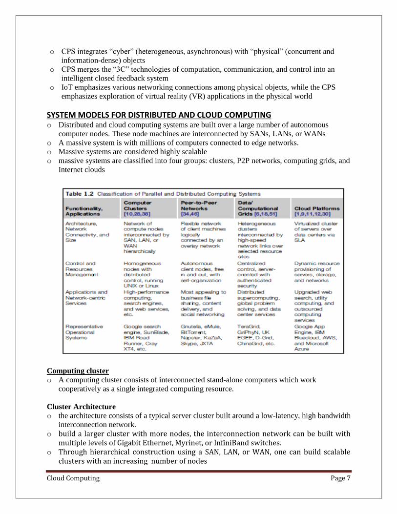
o massive systems are classified into four groups: clusters, P2P networks, computing grids, and
Internet clouds
Computing cluster
o A computing cluster consists of interconnected stand-alone computers which work
cooperatively as a single integrated computing resource.
Cluster Architecture
o the architecture consists of a typical server cluster built around a low-latency, high bandwidth
interconnection network.
o build a larger cluster with more nodes, the interconnection network can be built with multiple levels of Gigabit Ethernet, Myrinet, or InfiniBand switches.
o Through hierarchical construction using a SAN, LAN, or WAN, one can build scalable clusters with an increasing number of nodes
Cloud Computing Page 8
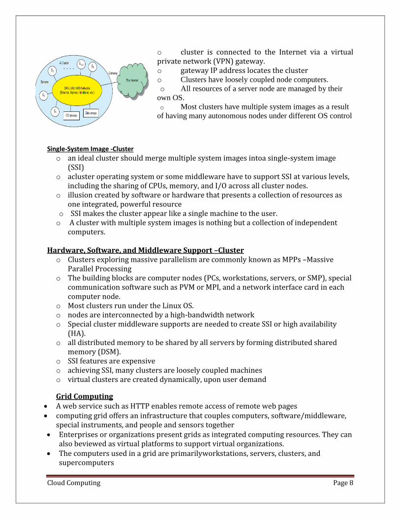
o cluster is connected to the Internet via a virtual private network (VPN) gateway. o gateway IP address locates the cluster o Clusters have loosely coupled node computers.
o All resources of a server node are managed by their
own OS.
o Most clusters have multiple system images as a result
of having many autonomous nodes under different OS control
Single-System Image -Cluster
o an ideal cluster should merge multiple system images intoa single-system image (SSI)
o acluster operating system or some middleware have to support SSI at various levels, including the sharing of CPUs, memory, and I/O across all cluster nodes.
o illusion created by software or hardware that presents a collection of resources as one integrated, powerful resource
o SSI makes the cluster appear like a single machine to the user. o A cluster with multiple system images is nothing but a collection of independent
computers.
Hardware, Software, and Middleware Support –Cluster o Clusters exploring massive parallelism are commonly known as MPPs –Massive
Parallel Processing o The building blocks are computer nodes (PCs, workstations, servers, or SMP), special
communication software such as PVM or MPI, and a network interface card in each computer node.
o Most clusters run under the Linux OS. o nodes are interconnected by a high-bandwidth network o Special cluster middleware supports are needed to create SSI or high availability
(HA). o all distributed memory to be shared by all servers by forming distributed shared
memory (DSM). o SSI features are expensive o achieving SSI, many clusters are loosely coupled machines o virtual clusters are created dynamically, upon user demand
Grid Computing • A web service such as HTTP enables remote access of remote web pages • computing grid offers an infrastructure that couples computers, software/middleware,
special instruments, and people and sensors together • Enterprises or organizations present grids as integrated computing resources. They can
also beviewed as virtual platforms to support virtual organizations. • The computers used in a grid are primarilyworkstations, servers, clusters, and
supercomputers
Cloud Computing Page 9
Peer-to-Peer Network-P2P • P2P architecture offers a distributed model of networked systems. • P2P network is client-oriented instead of server-oriented • In a P2P system, every node acts as both a client and a server
• Peer machines are simply client computers connected to the Internet. • All client machines act autonomously to join or leave the system freely. This implies that
no master-slave relationship exists among the peers. • No central coordination or central database is needed. The system is self-organizing with
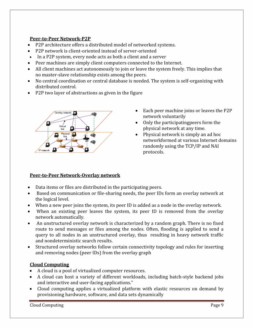
distributed control. • P2P two layer of abstractions as given in the figure
• Each peer machine joins or leaves the P2P network voluntarily
• Only the participatingpeers form the physical network at any time.
• Physical network is simply an ad hoc networkformed at various Internet domains randomly using the TCP/IP and NAI protocols.
Peer-to-Peer Network-Overlay network • Data items or files are distributed in the participating peers. • Based on communication or file-sharing needs, the peer IDs form an overlay network at
the logical level. • When a new peer joins the system, its peer ID is added as a node in the overlay network. • When an existing peer leaves the system, its peer ID is removed from the overlay
network automatically. • An unstructured overlay network is characterized by a random graph. There is no fixed
route to send messages or files among the nodes. Often, flooding is applied to send a query to all nodes in an unstructured overlay, thus resulting in heavy network traffic and nondeterministic search results.
• Structured overlay networks follow certain connectivity topology and rules for inserting and removing nodes (peer IDs) from the overlay graph
Cloud Computing • A cloud is a pool of virtualized computer resources. • A cloud can host a variety of different workloads, including batch-style backend jobs
and interactive and user-facing applications.” • Cloud computing applies a virtualized platform with elastic resources on demand by
provisioning hardware, software, and data sets dynamically
Cloud Computing Page 10
The Cloud Landscape Infrastructure as a Service (IaaS) • This model puts together infrastructures demanded by users—namely servers, storage,
networks, and the data center fabric. • The user can deploy and run on multiple VMs running guest OSes on specific
applications. • The user does not manage or control the underlying cloud infrastructure, but can
specify when to request and release the needed resources. Platform as a Service (PaaS) • This model enables the user to deploy user-built applications onto a virtualized cloud
platform. • PaaS includes middleware, databases, development tools, andsome runtime support
such as Web 2.0 and Java. • The platform includes both hardware andsoftware integrated with specific
programming interfaces. • The provider supplies the API andsoftware tools (e.g., Java, Python, Web 2.0, .NET). The
user is freed from managing the cloudinfrastructure. Software as a Service (SaaS) • This refers to browser-initiated application software overthousands of paid cloud
customers. • The SaaS model applies to business processes, industryapplications, consumer
relationship management (CRM), enterprise resources planning (ERP),human resources (HR), and collaborative applications.
• On the customer side, there is no upfrontinvestment in servers or software licensing. • On the provider side, costs are rather low, comparedwith conventional hosting of user
applications Internet clouds offer four deployment modes: private, public, managed, and hybrid SOFTWARE ENVIRONMENTS FOR DISTRIBUTED SYSTEMSAND CLOUDS Service-Oriented Architecture (SOA) • In grids/web services, Java, and CORBA, an entity is, respectively, a service, a Java
object, and a CORBA distributed object in a variety of languages. • These architectures build on the traditional seven Open Systems Interconnection (OSI)
layers that provide the base networking abstractions. • On top of this we have a base software environment, which would be
o .NET or Apache Axis for web services, o the Java Virtual Machine for Java, and a broker network for CORBA
• On top of this base environment one would build a higher level environment reflecting the special features of the distributed computing environment.
• SOAapplies to building grids, clouds, grids of clouds, clouds of grids, clouds of clouds (also known asinterclouds),
Cloud Computing Page 11
• SS (sensor service : A large number of sensors provide data-collectionservices (ZigBee device, a Bluetoothdevice, WiFi access point, a personal computer, a GPA, or a wireless phoneetc
• Filter services : to eliminate unwanted raw data, in orderto respond to specific requests from the web, the grid, or web services
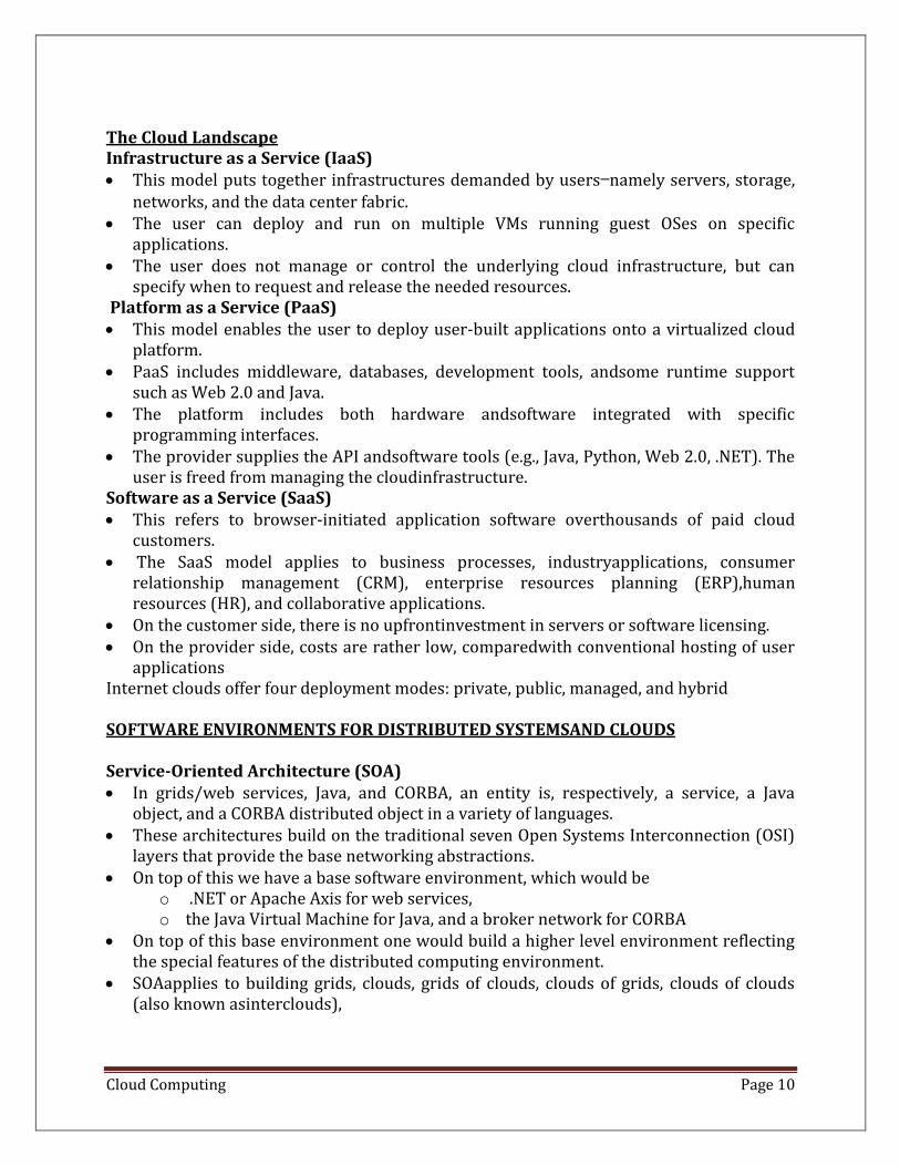
Layered Architecture for Web Services and Grids • Entity Interfaces • Java methodinterfaces correspond to the Web Services Description Language (WSDL), • CORBA interface - definition language (IDL) specifications • These interfaces are linked with customized, high-level communication systems: SOAP,
RMI, and IIOP • These communication systems support features including particular message patterns
(such as Remote Procedure Call or RPC), fault recovery, and specialized routing. • Communication systems are built on message-oriented middleware (enterprise bus)
infrastructure such as Web-Sphere MQ or Java Message Service (JMS)
Cases of fault tolerance- the features in the Web Services Reliable Messaging (WSRM) Security -reimplements the capabilities seen in concepts such as Internet Protocol Security (IPsec) Several models with, for example, JNDI (Jini and Java Naming and DirectoryInterface) illustrating different approaches within the Java distributed object model. The CORBA TradingService, UDDI (Universal Description, Discovery, and Integration), LDAP (Lightweight Directory Access Protocol), and ebXML (Electronic Business using eXtensibleMarkup Language earlier years, CORBA and Java approaches were used in distributed systems rather than today’sSOAP, XML, or REST (Representational State Transfer).
Web Services and Tools REST approach:
• delegates most ofthe difficult problems to application (implementation-specific) software. In a web services language
• minimal information in the header, and the message body (that is opaque to genericmessage processing) carries all the needed information.
• architectures are clearly more appropriatefor rapid technology environments. • REST can use XML schemas but not those that are part of SOAP; “XML overHTTP” is a
popular design choice in this regard. • Above the communication and managementlayers, we have the ability to compose new
entities or distributed programs by integrating severalentities together.
CORBA and Java:
Cloud Computing Page 12
• the distributed entities are linked with RPCs, and the simplest way to buildcomposite applications is to view the entities as objects and use the traditional ways of linking themtogether.
• For Java, this could be as simple as writing a Java program with method calls replaced byRemote Method Invocation (RMI),
• CORBA supports a similar model with a syntax reflecting theC++ style of its entity (object) interfaces.
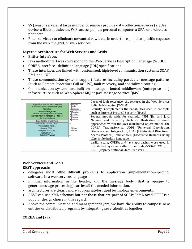
Parallel and Distributed Programming Models
PERFORMANCE, SECURITY, AND ENERGY EFFICIENCY
Performance Metrics:
• In a distributed system, performance is attributed to a large numberof factors. • System throughput is often measured in MIPS, Tflops (tera floating-point operations
persecond), or TPS (transactions per second). • Systemoverhead is often attributed to OS boot time, compile time, I/O data rate, and
the runtime support systemused. • Other performance-related metrics include the QoS for Internet and web services;
systemavailability and dependability; and security resilience for system defense against network attacks
Dimensions of Scalability
Cloud Computing Page 13
Any resource upgrade ina system should be backward compatible with existing hardware and software resources. System scaling can increase or decrease resources depending on many practicalfactors Size scalability • This refers to achieving higher performance or more functionality by increasingthe
machine size. • The word “size” refers to adding processors, cache, memory, storage, or I/Ochannels.
The most obvious way to determine size scalability is to simply count the number ofprocessors installed.
• Not all parallel computer or distributed architectures are equally sizescalable. • For example, the IBM S2 was scaled up to 512 processors in 1997. But in 2008,
theIBMBlueGene/L system scaled up to 65,000 processors. • Software scalability
• This refers to upgrades in the OS or compilers, adding mathematical andengineering libraries, porting new application software, and installing more user-friendlyprogramming environments.
• Some software upgrades may not work with large systemconfigurations. • Testing and fine-tuning of new software on larger systems is a nontrivial job.
• Application scalability • This refers to matching problem size scalability with machine sizescalability. • Problem size affects the size of the data set or the workload increase. Instead of
increasingmachine size, users can enlarge the problem size to enhance system efficiency or cost-effectiveness.
• Technology scalability • This refers to a system that can adapt to changes in building technologies,such as
the component and networking technologies • Whenscaling a system design with new technology one must consider three aspects:
time, space, andheterogeneity. • (1) Time refers to generation scalability. When changing to new-generation
processors,one must consider the impact to the motherboard, power supply, packaging and cooling,and so forth. Based on past experience, most systems upgrade their commodity processors everythree to five years.
• (2) Space is related to packaging and energy concerns. Technology scalabilitydemands harmony and portability among suppliers.
• (3) Heterogeneity refers to the use ofhardware components or software packages from different vendors. Heterogeneity may limit thescalability.
Amdahl’s Law
• Let the program has been parallelized or partitioned for parallelexecution on a cluster of many processing nodes.
• Assume that a fraction α of the code must be executedsequentially, called the sequential bottleneck.
Cloud Computing Page 14
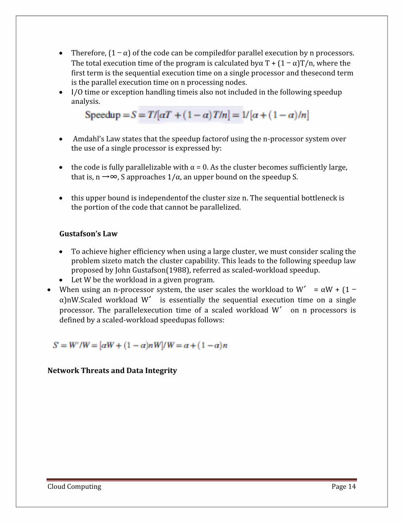
• Therefore, (1 − α) of the code can be compiledfor parallel execution by n processors.
The total execution time of the program is calculated byα T + (1 − α)T/n, where the first term is the sequential execution time on a single processor and thesecond term is the parallel execution time on n processing nodes.
• I/O time or exception handling timeis also not included in the following speedup analysis.
• Amdahl’s Law states that the speedup factorof using the n-processor system over the use of a single processor is expressed by:
• the code is fully parallelizable with α = 0. As the cluster becomes sufficiently large,
that is, n →∞, S approaches 1/α, an upper bound on the speedup S.
• this upper bound is independentof the cluster size n. The sequential bottleneck is the portion of the code that cannot be parallelized.
Gustafson’s Law
• To achieve higher efficiency when using a large cluster, we must consider scaling the problem sizeto match the cluster capability. This leads to the following speedup law proposed by John Gustafson(1988), referred as scaled-workload speedup.
• Let W be the workload in a given program. • When using an n-processor system, the user scales the workload to W′ = αW + (1 −
α)nW.Scaled workload W′ is essentially the sequential execution time on a single
processor. The parallelexecution time of a scaled workload W′ on n processors is defined by a scaled-workload speedupas follows:
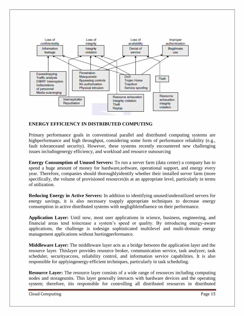
Network Threats and Data Integrity
Cloud Computing Page 15
ENERGY EFFICIENCY IN DISTRIBUTED COMPUTING
Primary performance goals in conventional parallel and distributed computing systems are
highperformance and high throughput, considering some form of performance reliability (e.g.,
fault toleranceand security). However, these systems recently encountered new challenging
issues includingenergy efficiency, and workload and resource outsourcing
Energy Consumption of Unused Servers: To run a server farm (data center) a company has to
spend a huge amount of money for hardware,software, operational support, and energy every
year. Therefore, companies should thoroughlyidentify whether their installed server farm (more
specifically, the volume of provisioned resources)is at an appropriate level, particularly in terms
of utilization.
Reducing Energy in Active Servers: In addition to identifying unused/underutilized servers for
energy savings, it is also necessary toapply appropriate techniques to decrease energy
consumption in active distributed systems with negligibleinfluence on their performance.
Application Layer: Until now, most user applications in science, business, engineering, and
financial areas tend toincrease a system’s speed or quality. By introducing energy-aware
applications, the challenge is todesign sophisticated multilevel and multi-domain energy
management applications without hurtingperformance.
Middleware Layer: The middleware layer acts as a bridge between the application layer and the
resource layer. Thislayer provides resource broker, communication service, task analyzer, task
scheduler, securityaccess, reliability control, and information service capabilities. It is also
responsible for applyingenergy-efficient techniques, particularly in task scheduling.
Resource Layer: The resource layer consists of a wide range of resources including computing
nodes and storageunits. This layer generally interacts with hardware devices and the operating
system; therefore, itis responsible for controlling all distributed resources in distributed
Cloud Computing Page 16
computing systems. Dynamic power management (DPM) and dynamic voltage-frequency
scaling (DVFS) are two popular methods incorporated into recent computer hardware systems.
In DPM, hardware devices, such as the CPU, have the capability to switch from idle mode to one
or more lower power modes. In DVFS, energy savings are achieved based on the fact that the
power consumptionin CMOS circuits has a direct relationship with frequency and the square of
the voltage supply.
Network Layer: Routing and transferring packets and enabling network services to the resource
layer are the mainresponsibility of the network layer in distributed computing systems. The
major challenge to buildenergy-efficient networks is, again, determining how to measure,
predict, and create a balancebetween energy consumption and performance.
Clustering for Massive Parallelism. • A computer cluster is a collection of interconnected stand-alone computers which can
work together collectively and cooperatively as a single integrated computing resource pool.
• Clustering explores massive parallelism at the job level and achieves high availability (HA) through stand-alone operations.
• Benefits of computer clusters and massively parallel processors (MPPs) include • Scalable performance, HA, fault tolerance, modular growth, and use of commodity
components. These features can sustain the generation changes experienced in hardware, software, and network components.
Design Objectives of Computer Clusters
Scalability: • Clustering of computers is based on the concept of modular growth. To scale a cluster
from hundreds of uniprocessor nodes to a supercluster with 10,000 multicore nodes is a nontrivial task.
• The scalability could be limited by a number of factors, such as the multicore chip technology, cluster topology, packaging method, power consumption, and cooling scheme applied.
Packaging • Cluster nodes can be packaged in a compact or a slack fashion. In a compact cluster, the
nodes are closely packaged in one or more racks sitting in a room, and the nodes are not attached to peripherals (monitors, keyboards, mice, etc.).
• In a slack cluster, the nodes are attached to their usual peripherals (i.e., they are complete SMPs, workstations, and PCs), and they may be located in different rooms, different buildings, or even remote regions.
• Packaging directly affects communication wire length, and thus the selection of interconnection technology used.
• While a compact cluster can utilize a high-bandwidth, low-latency communication network that is often proprietary, nodes of a slack cluster are normally connected through standard LANs or WANs.
Cloud Computing Page 17
Control
• A cluster can be either controlled or managed in a centralized or decentralized fashion. A compact cluster normally has centralized control, while a slack cluster can be controlled either way.
• In a centralized cluster, all the nodes are owned, controlled, managed, and administered by a central operator.
• In a decentralized cluster, the nodes have individual owners. This lack of a single point of control makes system administration of such a cluster very difficult. It also calls for special techniques for process scheduling, workload migration, checkpointing, accounting, and other similar tasks.
Homogeneity • A homogeneous cluster uses nodes from the same platform, that is, the same processor
architecture and the same operating system; often, the nodes are from the same vendors.
• A heterogeneous cluster uses nodes of different platforms. Interoperability is an
important issue in heterogeneous clusters.
• In a homogeneous cluster, a binary process image can migrate to another node and
continue execution.
• This is not feasible in a heterogeneous cluster, as the binary code will not be executable
when the process migrates to a node of a different platform.
Security
• Intracluster communication can be either exposed or enclosed.
• In an exposed cluster, the communication paths among the nodes are exposed to the
outside world. An outside machine can access the communication paths, and thus
individual nodes, using standard protocols (e.g., TCP/IP).
• Such exposed clusters are easy to implement, but have several disadvantages:
• Being exposed, intracluster communication is not secure, unless the
communication subsystemperforms additional work to ensure privacy and security.
• Outside communications may disrupt intracluster communications in an unpredictable
fashion.
• Standard communication protocols tend to have high overhead.
• In an enclosed cluster, intracluster communication is shielded from the outside world,
which
• alleviates the aforementioned problems.
• A disadvantage is that there is currently no standard for efficient, enclosed intracluster communication. Consequently, most commercial or academic clusters realize fast communications through one-of-a-kind protocols
Cloud Computing Page 18
Fundamental Cluster Design Issues
1. Scalable Performance: Scaling of resources (cluster nodes, memory capacity, I/O
bandwidth, etc.) leads to a proportional increase in performance. Both scale-up and scale-
down capabilities are needed, depending on application demand or cost-effectiveness
considerations. Clustering is driven by scalability
2. Single-System Image (SSI): A set of workstations connected by an Ethernet network is
not necessarily a cluster. A cluster is a single system.
3. Availability Support: Clusters can provide cost-effective HA capability with lots of
redundancy in processors, memory, disks, I/O devices, networks, and operating system
images
4. Cluster Job Management: Clusters try to achieve high system utilization from
traditional workstations or PC nodes that are normally not highly utilized. Job
management software is required to provide batching, load balancing, parallel processing,
and other functionality
5. Inter node Communication: The inter node physical wire lengths are longer in a cluster
than in an MPP. A long wire implies greater interconnect network latency. But, longer
wires have more problems in terms of reliability, clock skew, and cross talking. These
problems call for reliable and secure communication protocols, which increase overhead.
Clusters often use commodity networks (e.g., Ethernet) with standard protocols such as
TCP/IP.
6. Fault Tolerance and Recovery: Clusters of machines can be designed to eliminate all
single points of failure. Through redundancy, a cluster can tolerate faulty conditions up to
a certain extent. Heartbeat mechanisms can be installed to monitor the running condition
of all nodes. In case of a node failure, critical jobs running on the failing nodes can be
saved by failing over to the surviving node machines. Rollback recovery schemes restore
the computing results through periodic checkpointing.
7. Cluster Family Classification:computer clusters are divided into three classes
• Compute clusters:
o These are clusters designed mainly for collective computationover a single large job.
The compute clusters do not handle many I/O operations, such as database services.
When a single compute job requires frequent communication among the cluster
nodes, the cluster must share a dedicated network, and thus the nodes are mostly
homogeneous and tightly coupled. This type of clusters is also known as a Beowulf
cluster
• High-Availability clusters HA (high-availability)
Cloud Computing Page 19
o clusters are designed to be fault-tolerant and achieve HA of services. HA clusters
operate with many redundant nodes to sustain faults or failures.
• Load-balancing clusters
o These clusters shoot for higher resource utilization through load balancing among all
participating nodes in the cluster. All nodes share the workload or function as a single
virtual machine (VM).
o Requests initiated from the user are distributed to all node computers to form a
cluster. This results in a balanced workload among different machines, and thus
higher resource utilization or higher performance. Middleware is needed to achieve
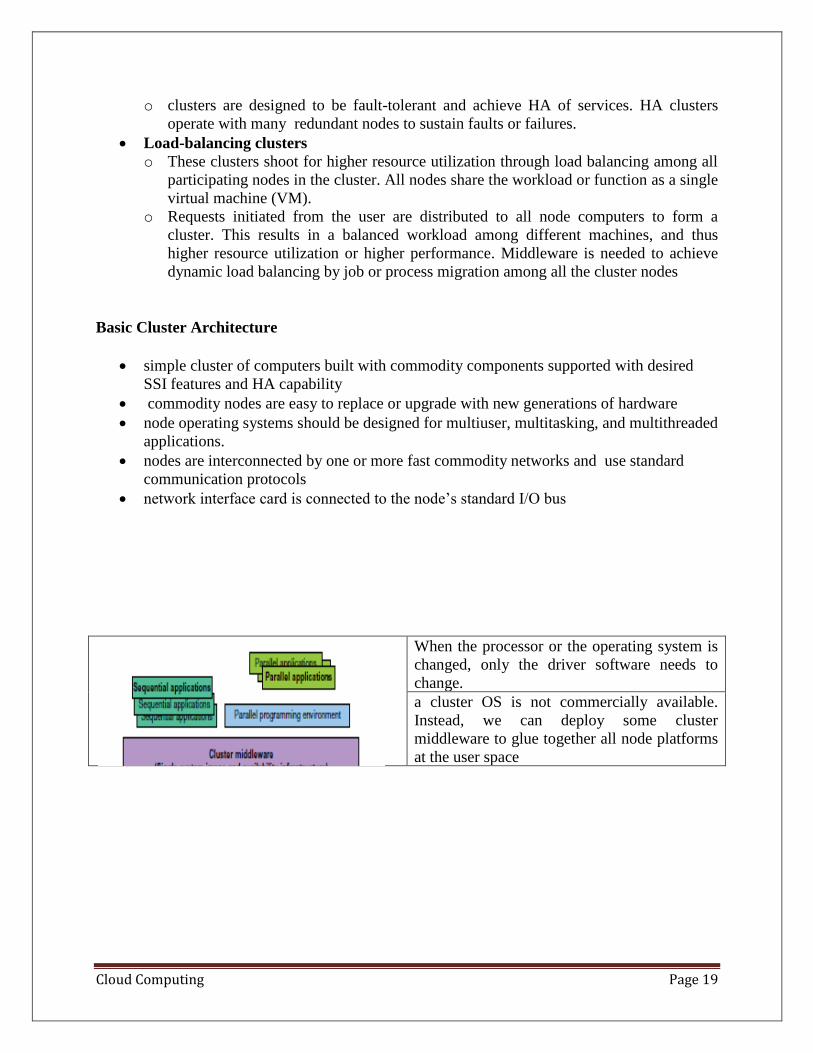
dynamic load balancing by job or process migration among all the cluster nodes Basic Cluster Architecture
• simple cluster of computers built with commodity components supported with desired
SSI features and HA capability • commodity nodes are easy to replace or upgrade with new generations of hardware • node operating systems should be designed for multiuser, multitasking, and multithreaded
applications.
• nodes are interconnected by one or more fast commodity networks and use standard
communication protocols
• network interface card is connected to the node’s standard I/O bus
When the processor or the operating system is
changed, only the driver software needs to
change.
a cluster OS is not commercially available.
Instead, we can deploy some cluster
middleware to glue together all node platforms
at the user space
Cloud Computing Page 20
• middleware offers HA services
• An SSI layer provides a single entry point,
a single file hierarchy, a single point of
control
• idealized cluster is supported by three
subsystems
• conventional databasesand OLTP monitors
• A user interface subsystemis needed to
combine the advantages of the web
interface and the Windows GUI.
• cluster supports parallel programming
based on standard languages and
communication libraries using PVM, MPI,
or OpenMP. The programming
environment also includes tools for
debugging, profiling, monitoring
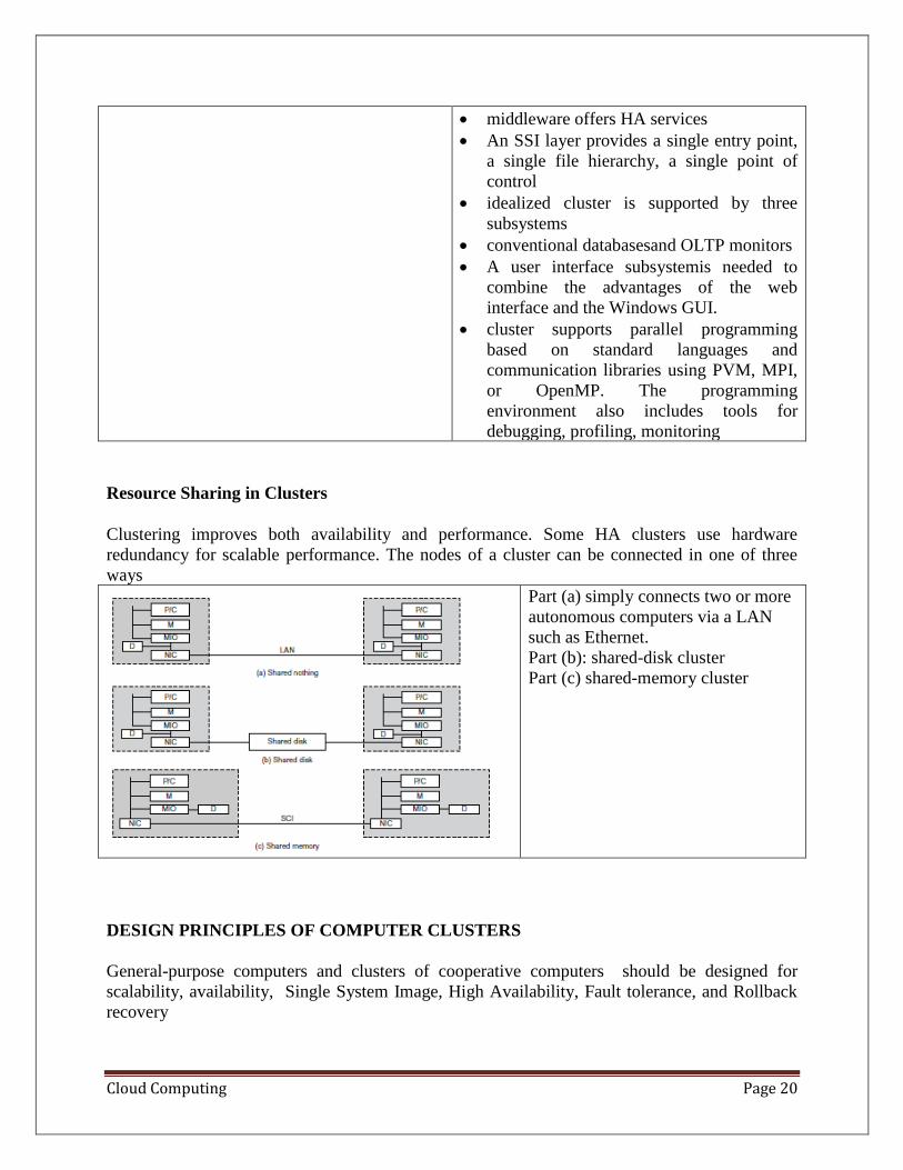
Resource Sharing in Clusters
Clustering improves both availability and performance. Some HA clusters use hardware
redundancy for scalable performance. The nodes of a cluster can be connected in one of three
ways
Part (a) simply connects two or more
autonomous computers via a LAN
such as Ethernet.
Part (b): shared-disk cluster
Part (c) shared-memory cluster
DESIGN PRINCIPLES OF COMPUTER CLUSTERS
General-purpose computers and clusters of cooperative computers should be designed for
scalability, availability, Single System Image, High Availability, Fault tolerance, and Rollback
recovery
Cloud Computing Page 21
• Single System Image: A single system image is the illusion, created by software or hardware,
that presents a collection of resources as an integrated powerful resource. SSI makes the
cluster appear like a single machine to the user, applications, and network. A cluster with
multiple system images is nothing but a collection of independent computers Single-System-
Image Features
⚫ Single System: The entire cluster is viewed by the users as one system, which has
multiple processors.
⚫ Single Control: Logically, an end user or system user utilizes services from one place
with a single interface.
⚫ Symmetry: A user can use a cluster service from any node. All cluster services and
functionalities are symmetric to all nodes and all users, except those protected by access
rights.
⚫ Location Transparent: The user is not aware of the whereabouts of the physical device
that eventually provides a service.
Basic SSI Services
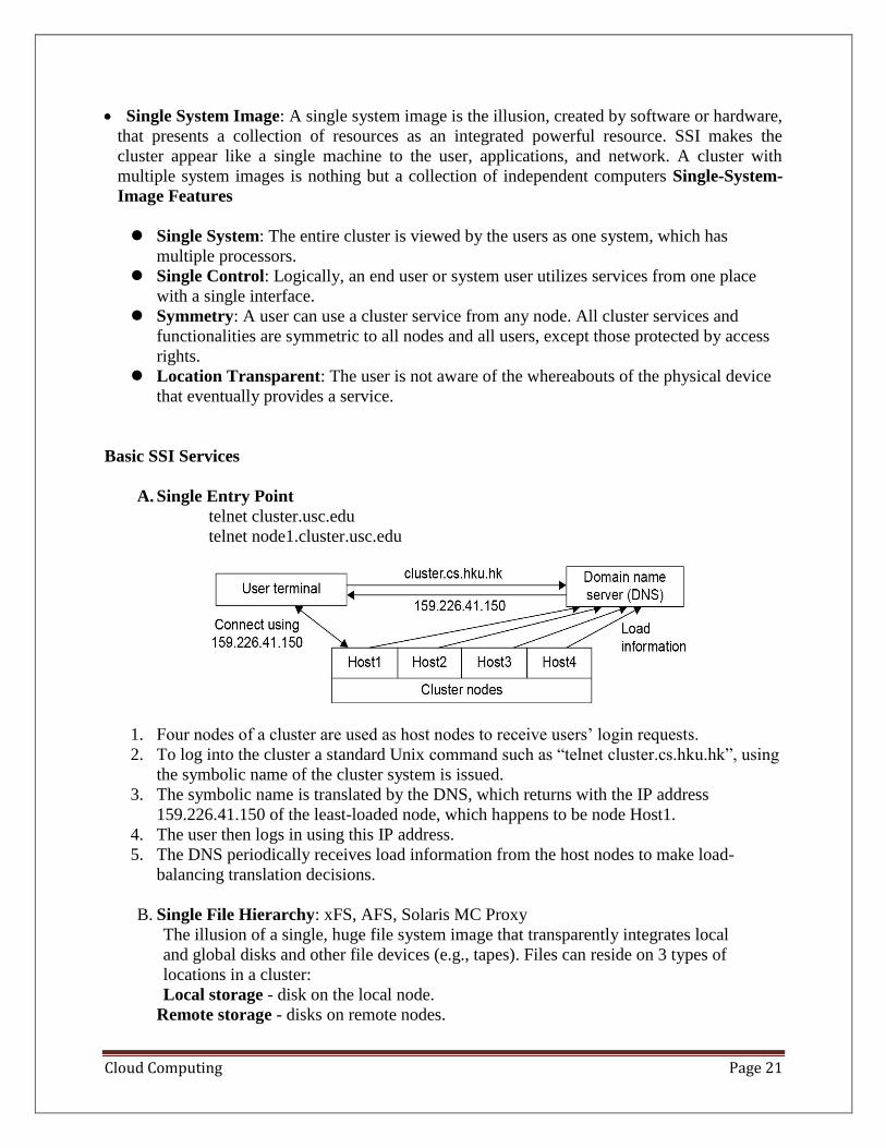
A. Single Entry Point
telnet cluster.usc.edu
telnet node1.cluster.usc.edu
1. Four nodes of a cluster are used as host nodes to receive users’ login requests.
2. To log into the cluster a standard Unix command such as “telnet cluster.cs.hku.hk”, using
the symbolic name of the cluster system is issued.
3. The symbolic name is translated by the DNS, which returns with the IP address
159.226.41.150 of the least-loaded node, which happens to be node Host1.
4. The user then logs in using this IP address.
5. The DNS periodically receives load information from the host nodes to make load-
balancing translation decisions.
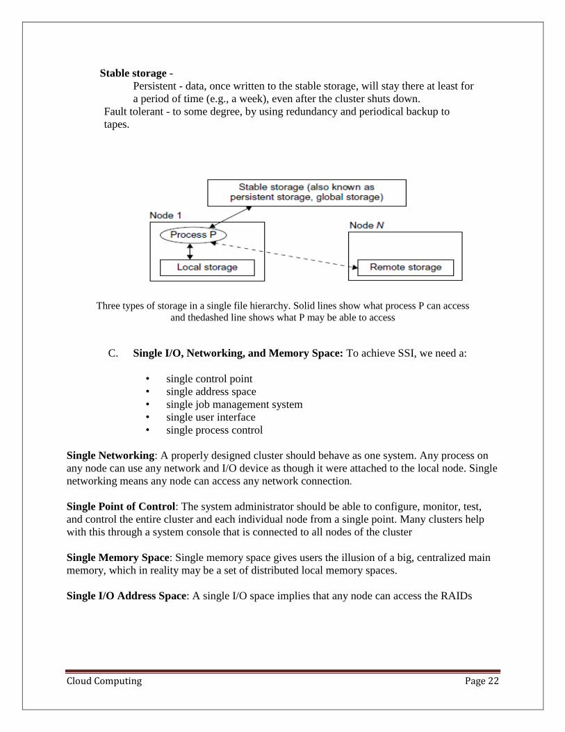
B. Single File Hierarchy: xFS, AFS, Solaris MC Proxy
The illusion of a single, huge file system image that transparently integrates local
and global disks and other file devices (e.g., tapes). Files can reside on 3 types of
locations in a cluster:
Local storage - disk on the local node.
Remote storage - disks on remote nodes.
Cloud Computing Page 22
Stable storage -
Persistent - data, once written to the stable storage, will stay there at least for
a period of time (e.g., a week), even after the cluster shuts down.
Fault tolerant - to some degree, by using redundancy and periodical backup to
tapes.
Three types of storage in a single file hierarchy. Solid lines show what process P can access
and thedashed line shows what P may be able to access
C. Single I/O, Networking, and Memory Space: To achieve SSI, we need a:
• single control point
• single address space
• single job management system
• single user interface
• single process control
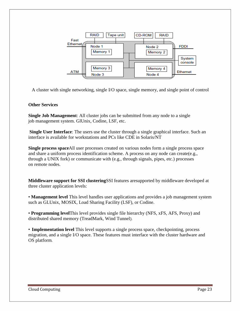
Single Networking: A properly designed cluster should behave as one system. Any process on
any node can use any network and I/O device as though it were attached to the local node. Single
networking means any node can access any network connection.
Single Point of Control: The system administrator should be able to configure, monitor, test,
and control the entire cluster and each individual node from a single point. Many clusters help
with this through a system console that is connected to all nodes of the cluster
Single Memory Space: Single memory space gives users the illusion of a big, centralized main
memory, which in reality may be a set of distributed local memory spaces.
Single I/O Address Space: A single I/O space implies that any node can access the RAIDs
Cloud Computing Page 23
A cluster with single networking, single I/O space, single memory, and single point of control
Other Services
Single Job Management: All cluster jobs can be submitted from any node to a single
job management system. GlUnix, Codine, LSF, etc.
Single User Interface: The users use the cluster through a single graphical interface. Such an
interface is available for workstations and PCs like CDE in Solaris/NT
Single process spaceAll user processes created on various nodes form a single process space
and share a uniform process identification scheme. A process on any node can create(e.g.,
through a UNIX fork) or communicate with (e.g., through signals, pipes, etc.) processes
on remote nodes.
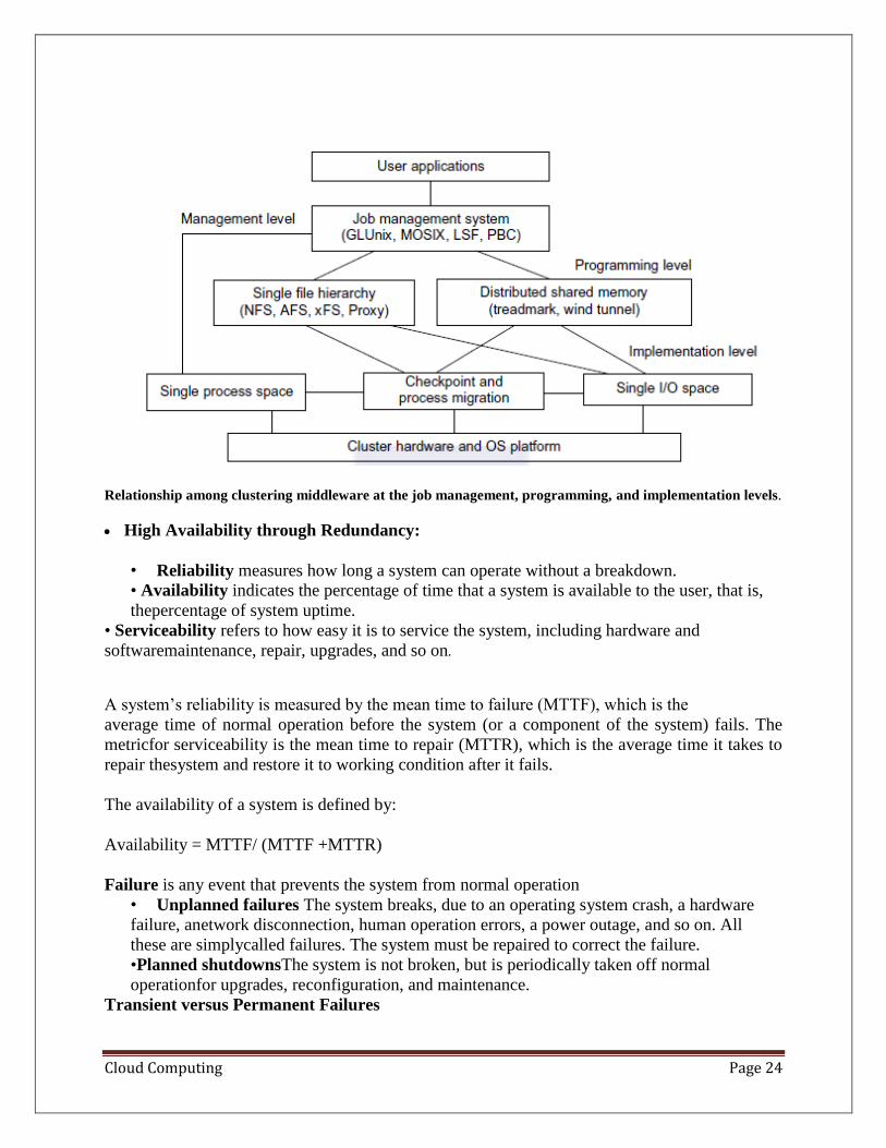
Middleware support for SSI clusteringSSI features aresupported by middleware developed at
three cluster application levels:
• Management level This level handles user applications and provides a job management system
such as GLUnix, MOSIX, Load Sharing Facility (LSF), or Codine.
• Programming levelThis level provides single file hierarchy (NFS, xFS, AFS, Proxy) and
distributed shared memory (TreadMark, Wind Tunnel).
• Implementation level This level supports a single process space, checkpointing, process
migration, and a single I/O space. These features must interface with the cluster hardware and
OS platform.
Cloud Computing Page 24
Relationship among clustering middleware at the job management, programming, and implementation levels.
• High Availability through Redundancy:
• Reliability measures how long a system can operate without a breakdown.
• Availability indicates the percentage of time that a system is available to the user, that is,
thepercentage of system uptime.
• Serviceability refers to how easy it is to service the system, including hardware and
softwaremaintenance, repair, upgrades, and so on.
A system’s reliability is measured by the mean time to failure (MTTF), which is the
average time of normal operation before the system (or a component of the system) fails. The
metricfor serviceability is the mean time to repair (MTTR), which is the average time it takes to
repair thesystem and restore it to working condition after it fails.
The availability of a system is defined by:
Availability = MTTF/ (MTTF +MTTR)
Failure is any event that prevents the system from normal operation
• Unplanned failures The system breaks, due to an operating system crash, a hardware
failure, anetwork disconnection, human operation errors, a power outage, and so on. All
these are simplycalled failures. The system must be repaired to correct the failure.
•Planned shutdownsThe system is not broken, but is periodically taken off normal
operationfor upgrades, reconfiguration, and maintenance.
Transient versus Permanent Failures
Cloud Computing Page 25
A lot of failures are transient in that they occur temporarily and then disappear. They can be
dealtwith without replacing any components. A standard approach is to roll back the system to a
known state and start over.
Permanent failures cannot be corrected by rebooting. Some hardwareor software component
must be repaired or replaced. For instance, rebooting will not work ifthe system hard disk is
broken.
Partial versus Total Failures
A failure that renders the entire system unusable is called a total failure. A failure that only
affectspart of the system is called a partial failure if the system is still usable, even at a reduced
capacity
Redundancy Techniques
Isolated Redundancy: A key technique to improve availability in any system is to use
redundant components. When acomponent (the primary component) fails, the service it provided
is taken over by another component(the backup component). Furthermore, the primary and the
backup components should be isolatedfrom each other, meaning they should not be subject to the
same cause of failure. Clustersprovide HA with redundancy in power supplies, fans, processors,
memories, disks, I/O devices, networks,operating system images, and so on. In a carefully
designed cluster, redundancy is also isolated.
N-Version Programming to Enhance Software Reliability
A common isolated-redundancy approach to constructing a mission-critical software system is
calledN-version programming. The software is implemented by N isolated teams who may not
even knowthe others exist. Different teams are asked to implement the software using different
algorithms,programming languages, environment tools, and even platforms In a fault-tolerant
system, the N versions all run simultaneously and their results are constantly compared. If the
results differ, thesystem is notified that a fault has occurred.
• Fault-Tolerant Cluster Configurations: The cluster solution was targeted to provide
availability support for two server nodes with threeascending levels of availability: hot
standby, active takeover, and fault-tolerant. The level of availabilityincreases from standby to
active and fault-tolerant cluster configurations. The shorter is the recoverytime, the higher is
the cluster availability. Failback refers to the ability of a recovered node returningto normal
operation after repair or maintenance. Activeness refers to whether the node is used inactive
work during normal operation.
• Hot standby server clusters: In a hot standby cluster, only the primary node is actively doing
all the useful work normally. The standby node is powered on (hot) and running some
monitoring programs to communicate heartbeat signals to check the status of the primary
node, but is not actively running other useful workloads. The primary node must mirror any
data to shared disk storage, which is accessible by the standby node. The standby node
requires a second copy of data.
Cloud Computing Page 26
• Active-takeover clusters: In this case, the architecture is symmetric among multiple server
nodes. Both servers are primary, doing useful work normally. Both failover and failback are
often supported on both server nodes. When a node fails, the user applications fail over to
the available node in the cluster. Depending on the time required to implement the failover,
users may experience some delays or may lose some data that was not saved in the last
checkpoint.
• Failover cluster: When a component fails, this technique allows the remaining system to
take over the services originally provided by the failed component. A failover mechanism
mustprovide several functions, such as failure diagnosis, failure notification, and failure
recovery.Failure diagnosis refers to the detection of a failure and the location of the failed
componentthat caused the failure. A commonly used technique is heartbeat, whereby the
cluster nodessend out a stream of heartbeat messages to one another. If the system does not
receive thestream of heartbeat messages from a node, it can conclude that either the node or
the networkconnection has failed.
Recovery Schemes
Failure recovery refers to the actions needed to take over the workload of a failed component.
Thereare two types of recovery techniques. In backward recovery, the processes running on a
cluster periodicallysave a consistent state (called a checkpoint) to a stable storage. After a failure,
the systemis reconfigured to isolate the failed component, restores the previous checkpoint, and
resumes normaloperation. This is called rollback. Backward recovery is relatively easy to
implement in an application-independent, portable fashion
If execution time is crucial,such as in real-time systems where the rollback time cannot be
tolerated, a forward recovery schemeshould be used. With such a scheme, the system is not
rolled back to the previous checkpoint upon afailure. Instead, the system utilizes the failure
diagnosis information to reconstruct a valid system stateand continues execution. Forward
recovery is application-dependent and may need extra hardware
Checkpointing and Recovery Techniques
Checkpointingisthe process of periodically saving the state of an executing program to stable
storage, from whichthe system can recover after a failure. Each program state saved is called a
checkpoint. The disk filethat contains the saved state is called the checkpoint file.
Checkpointing techniques are useful not only for availability, but also for program debugging,
process migration, and load balancing
Checkpointing can be realized by the operating system at the kernel level, where the OS
transparentlycheckpoints and restarts processes
A less transparent approach linksthe user code with a checkpointinglibrary in the user space.
Checkpointing and restarting are handled by this runtime support. This approach is used widely
because it has the advantage thatuser applications do not have to be modified.
Cloud Computing Page 27
A third approach requires the user (or the compiler) to insert checkpointingfunctions in the
application; thus, the application has to be modified, and the transparencyis lost. However, it has
the advantage that the user can specify where to checkpoint. This is helpful to reduce
checkpointing overhead. Checkpointing incurs both time and storage overheads.
Checkpoint Overheads
During a program’s execution, its states may be saved many times. This is denoted by the time
consumedto save one checkpoint. The storage overhead is the extra memory and disk space
requiredfor checkpointing. Both time and storage overheads depend on the size of the checkpoint
file.
Choosing an Optimal Checkpoint Interval
The time period between two checkpoints is called the checkpoint interval. Making the interval
larger can reduce checkpoint time overhead.
Wong and Franklin derived an expression for optimal checkpoint interval
Optimal checkpoint interval = Square root (MTTF x tc)/h
MTTF is the system’s mean time to failure. This MTTF accounts the time consumed to
save one checkpoint, and h is the average percentage of normal computation performed in a
checkpointinterval before the system fails. The parameter h is always in the range. After a
system isrestored, it needs to spend h × (checkpoint interval) time to recompute.
Incremental Checkpoint
Instead of saving the full state at each checkpoint, an incremental checkpoint scheme saves only
theportion of the state that is changed from the previous checkpoint In full-state checkpointing,
only one checkpoint file needs to be kepton disk. Subsequent checkpoints simply overwrite this
file. With incremental checkpointing, old filesneeded to be kept, because a state may span many
files. Thus, the total storage requirement is larger
Forked Checkpointing
Most checkpoint schemes are blocking in that the normal computation is stopped while
checkpointingis in progress. With enough memory, checkpoint overhead can be reduced by
making a copy ofthe program state in memory and invoking another asynchronous thread to
perform the checkpointingconcurrently. A simple way to overlap checkpointing with
computation is to use the UNIXfork( ) system call. The forked child process duplicates the parent
process’s address space andcheckpoints it. Meanwhile, the parent process continues execution.
Overlapping is achieved sincecheckpointing is disk-I/O intensive
User-Directed Checkpointing
The checkpoint overheads can sometimes be substantially reduced if the user inserts code (e.g.,
library or system calls) to tell the system when to save, what to save, and what not to save. What
should be the exact contents of a checkpoint? It should contain just enough information to allow
asystem to recover. The state of a process includes its data state and control state
Cloud Computing Page 28
Checkpointing Parallel Programs The state of a parallel program is usually much larger
than that of a sequential program, as it consists of the set of the states of individual processes,
plus thestate of the communication network. Parallelism also introduces various timing and
consistency problems
Consistent Snapshot
A global snapshot is called consistent if there is no message that is received by the checkpoint of
one process, but not yet sent by another process. Graphically, this corresponds to the case that no
arrow crosses a snapshot line from right to left
Coordinated versus Independent Checkpointing
Checkpointing schemes for parallel programs can be classified into two types. In coordinated
checkpointing(also called consistent checkpointing), the parallel program is frozen, and all
processes arecheckpointed at the same time. In independent checkpointing, the processes are
checkpointed independentof one another.
Cluster Job Scheduling and Management
A Job Management System (JMS) should have three parts:
⚫ A user server lets the user submit jobs to one or more queues, specify resource
requirements for each job, delete a job from a queue, inquire about the status of a job or a
queue.
⚫ A job scheduler that performs job scheduling and queuing according to job types,
resource requirements, resource availability, and scheduling policies.
⚫ A resource manager that allocates and monitors resources, enforces scheduling policies,
and collects accounting information.
JMS Administration
⚫ JMS should be able to dynamically reconfigure the cluster with minimal impact on the
running jobs.
⚫ The administrator’s prologue and epilogue scripts should be able to run before and after
each job for security checking, accounting, and cleanup.
⚫ Users should be able to cleanly kill their own jobs.
⚫ The administrator or the JMS should be able to cleanly suspend or kill any job.
➢ Clean means that when a job is suspended or killed, all its processes must be
included.
➢ Otherwise some “orphan” processes are left in the system, wasting cluster
resources and may eventually render the system unusable.
Several types of jobs execute on a cluster.
⚫ Serial jobs run on a single node.
⚫ Parallel jobs use multiple nodes.
Cloud Computing Page 29
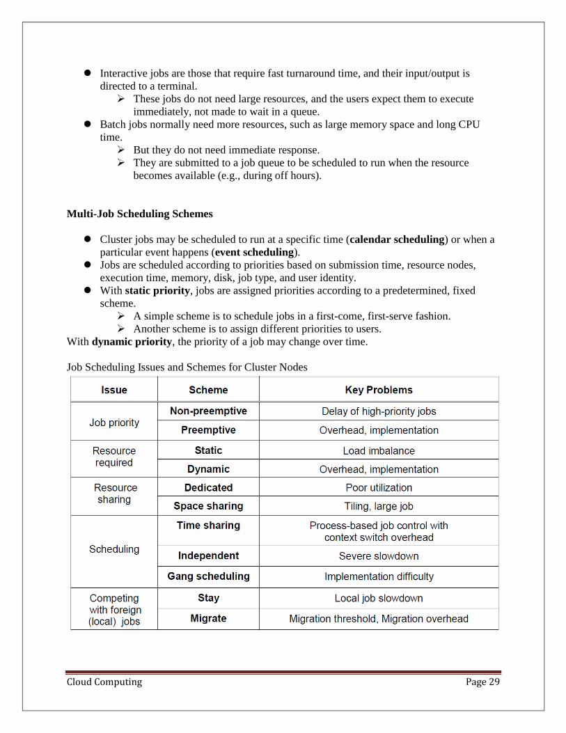
⚫ Interactive jobs are those that require fast turnaround time, and their input/output is
directed to a terminal.
➢ These jobs do not need large resources, and the users expect them to execute
immediately, not made to wait in a queue.
⚫ Batch jobs normally need more resources, such as large memory space and long CPU
time.
➢ But they do not need immediate response.
➢ They are submitted to a job queue to be scheduled to run when the resource
becomes available (e.g., during off hours).
Multi-Job Scheduling Schemes
⚫ Cluster jobs may be scheduled to run at a specific time (calendar scheduling) or when a
particular event happens (event scheduling).
⚫ Jobs are scheduled according to priorities based on submission time, resource nodes,
execution time, memory, disk, job type, and user identity.
⚫ With static priority, jobs are assigned priorities according to a predetermined, fixed
scheme.
➢ A simple scheme is to schedule jobs in a first-come, first-serve fashion.
➢ Another scheme is to assign different priorities to users.
With dynamic priority, the priority of a job may change over time.
Job Scheduling Issues and Schemes for Cluster Nodes
Cloud Computing Page 30
Scheduling Modes
Dedicated Mode:
⚫ Only one job runs in the cluster at a time, and at most one process of the job is assigned
to a node at a time.
⚫ The single job runs until completion before it releases the cluster to run other jobs.
Space Sharing:
Multiple jobs can run on disjoint partitions (groups) of nodes simultaneously.
⚫ At most one process is assigned to a node at a time.
⚫ Although a partition of nodes is dedicated to a job, the interconnect and the I/O
subsystem may be shared by all jobs.
Time sharing :
⚫ Multiple user processes are assigned to the same node.
Time-sharing introduces the following parallel scheduling policies:
⚫ Independent Scheduling (Independent): Uses the operating system of each
cluster node to schedule different processes as in a traditional workstation.
⚫ Gang Scheduling: Schedules all processes of a parallel job together. When one
process is active, all processes are active.
⚫ Competition with Foreign (Local) Jobs: Scheduling becomes more complicated
when both cluster jobs and local jobs are running. The local jobs should have
priority over cluster jobs.
1. Migration Scheme IssuesNode Availability: Can the job find another available node to
migrate to?
➢ Berkeley study : Even during peak hours, 60% of workstations in a cluster are
available.
2. Migration Overhead: The migration time can significantly slow down a parallel job.
➢ Berkeley study : a slowdown as great as 2.4 times.
➢ Slowdown is less if a parallel job is run on a cluster of twice the size.
➢ e.g. a 32-node job on a 60-node cluster – migration slowdown no more than 20%,
even when migration time of 3 minutes.
3. Recruitment Threshold: the amount of time a workstation stays unused before the
cluster considers it an idle node.
Cloud Computing Page 31
UNIT -2
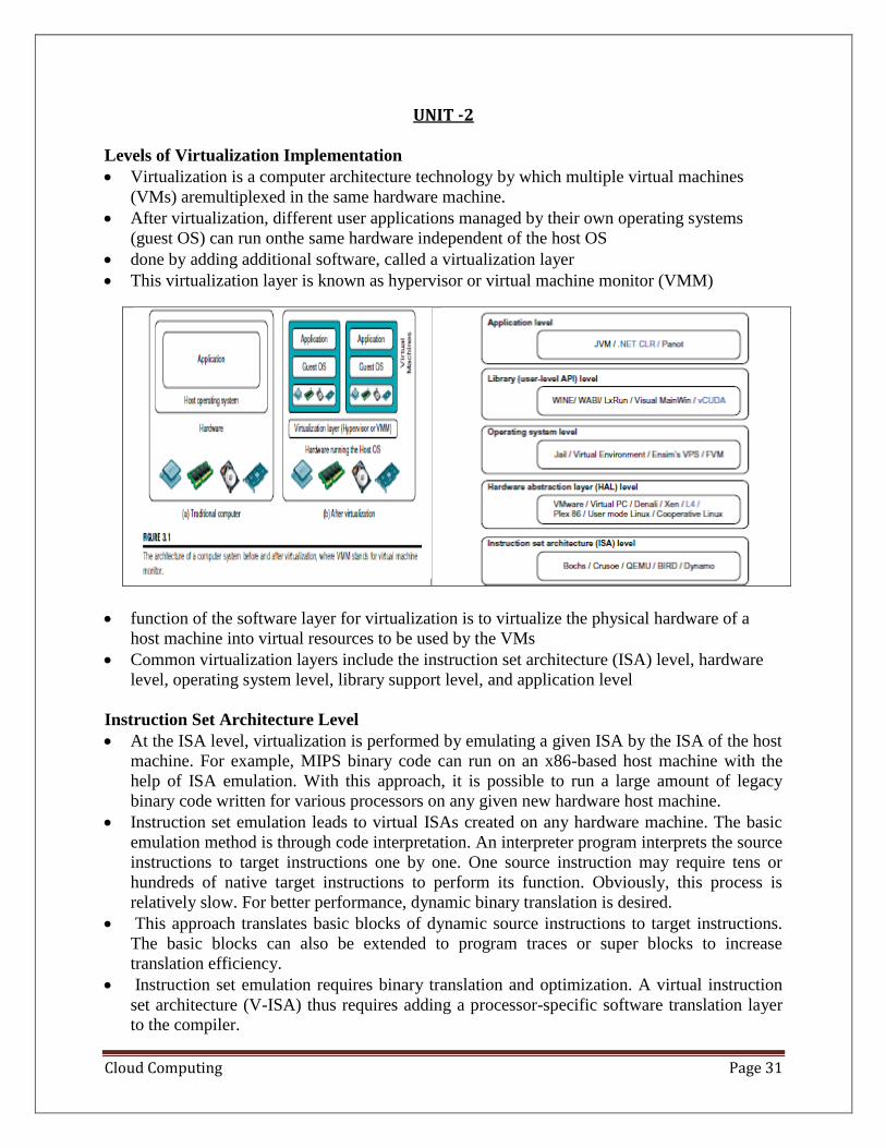
Levels of Virtualization Implementation
• Virtualization is a computer architecture technology by which multiple virtual machines
(VMs) aremultiplexed in the same hardware machine.
• After virtualization, different user applications managed by their own operating systems
(guest OS) can run onthe same hardware independent of the host OS
• done by adding additional software, called a virtualization layer
• This virtualization layer is known as hypervisor or virtual machine monitor (VMM)
• function of the software layer for virtualization is to virtualize the physical hardware of a
host machine into virtual resources to be used by the VMs
• Common virtualization layers include the instruction set architecture (ISA) level, hardware
level, operating system level, library support level, and application level
Instruction Set Architecture Level
• At the ISA level, virtualization is performed by emulating a given ISA by the ISA of the host
machine. For example, MIPS binary code can run on an x86-based host machine with the
help of ISA emulation. With this approach, it is possible to run a large amount of legacy
binary code written for various processors on any given new hardware host machine.
• Instruction set emulation leads to virtual ISAs created on any hardware machine. The basic
emulation method is through code interpretation. An interpreter program interprets the source
instructions to target instructions one by one. One source instruction may require tens or
hundreds of native target instructions to perform its function. Obviously, this process is
relatively slow. For better performance, dynamic binary translation is desired.
• This approach translates basic blocks of dynamic source instructions to target instructions.
The basic blocks can also be extended to program traces or super blocks to increase
translation efficiency.
• Instruction set emulation requires binary translation and optimization. A virtual instruction
set architecture (V-ISA) thus requires adding a processor-specific software translation layer
to the compiler.
Cloud Computing Page 32
Hardware Abstraction Level
• Hardware-level virtualization is performed right on top of the bare hardware.
• Thisapproach generates a virtual hardware environment for a VM.
• The process managesthe underlying hardware through virtualization. The idea is to virtualize
a computer’s resources, such asits processors, memory, and I/O devices.
• The intention is to upgrade the hardware utilization rate bymultiple users concurrently. The
idea was implemented in the IBM VM/370 in the 1960s.
• Morerecently, the Xen hypervisor has been applied to virtualize x86-based machines to run
Linux or otherguest OS applications.
Operating System Level
• This refers to an abstraction layer between traditional OS and user applications.
• OS-level virtualizationcreates isolated containers on a single physical server and the OS
instances to utilize the hardwareand software in data centers.
• The containers behave like real servers.
• OS-level virtualization iscommonly used in creating virtual hosting environments to allocate
hardware resources among alarge number of mutually distrusting users.
• It is also used, to a lesser extent, in consolidating serverhardware by moving services on
separate hosts into containers or VMs on one server.
Library Support Level
• Most applications use APIs exported by user-level libraries rather than using lengthy system
callsby the OS.
• Since most systems provide well-documented APIs, such an interface becomes
anothercandidate for virtualization.
• Virtualization with library interfaces is possible by controlling the communicationlink
between applications and the rest of a system through API hooks.
User-Application Level
• Virtualization at the application level virtualizes an application as a VM.
• On a traditional OS, anapplication often runs as a process. Therefore, application-level
virtualization is also known as process-level virtualization.
• The most popular approach is to deploy high level language (HLL)VMs. In this scenario, the
virtualization layer sits as an application program on top of the operatingsystem,
• The layer exports an abstraction of a VM that can run programs written and compiledto a
particular abstract machine definition.
• Any program written in the HLL and compiled for thisVM will be able to run on it. The
Microsoft .NET CLR and Java Virtual Machine (JVM) are twogood examples of this class of
VM.
VMM Design Requirements and Providers
• layer between real hardware and traditional operating systems. This layer is commonly
called the Virtual Machine Monitor (VMM)
• three requirements for a VMM
Cloud Computing Page 33
• a VMM should provide an environment for programs which is essentially identical to the
original machine
• programs run in this environment should show, at worst, only minor decreases in speed
• VMM should be in complete control of the system resources.
• VMM includes the following aspects:
• (1) The VMM is responsible for allocating hardware resources for programs;
• (2) it is not possible for a program to access any resource not explicitly allocated to it;
• (3) it is possible under certain circumstances for a VMM to regain control of resources
already allocated.
Virtualization Support at the OS Level
• Why OS-Level Virtualization? :
o it is slow to initialize a hardware-level VM because each VM creates its own
image from scratch.
• OS virtualization inserts a virtualization layer inside an operating system to partition a
machine’s physical resources.
• It enables multiple isolated VMs within a single operating system kernel.
• This kind of VM is often called a virtual execution environment (VE), Virtual Private
System (VPS), or simply container
• The benefits of OS extensions are twofold:
o (1) VMs at the operating system level have minimal startup/shutdown costs, low
resource requirements, and high scalability;
o (2) for an OS-level VM, it is possible for a VM and its host environment to
synchronize state changes when necessary.
Middleware Support for Virtualization
• Library-level virtualization is also known as user-level Application Binary Interface
(ABI) or API emulation.
• This type of virtualization can create execution environments for running alien programs
on a platform
Hypervisor and Xen Architecture
• The hypervisor software sits directly between the physical hardware and its OS.
• This virtualization layer is referred to as either the VMM or the hypervisor
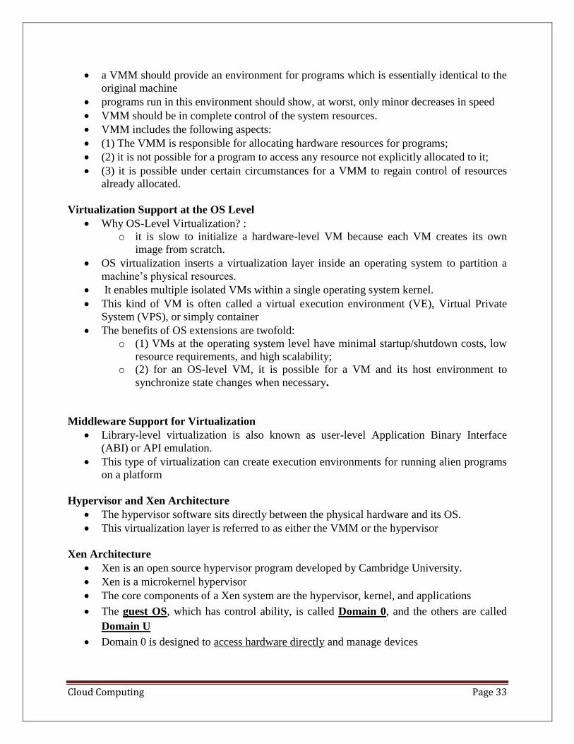
Xen Architecture
• Xen is an open source hypervisor program developed by Cambridge University.
• Xen is a microkernel hypervisor
• The core components of a Xen system are the hypervisor, kernel, and applications
• The guest OS, which has control ability, is called Domain 0, and the others are called
Domain U
• Domain 0 is designed to access hardware directly and manage devices
Cloud Computing Page 34
• VM state is akin to a tree: the current state of the machine is a point that progresses
monotonically as the software executes.
• VMs are allowed to roll back to previous states in their execution (e.g., to fix
configuration errors) or rerun from the same point many times
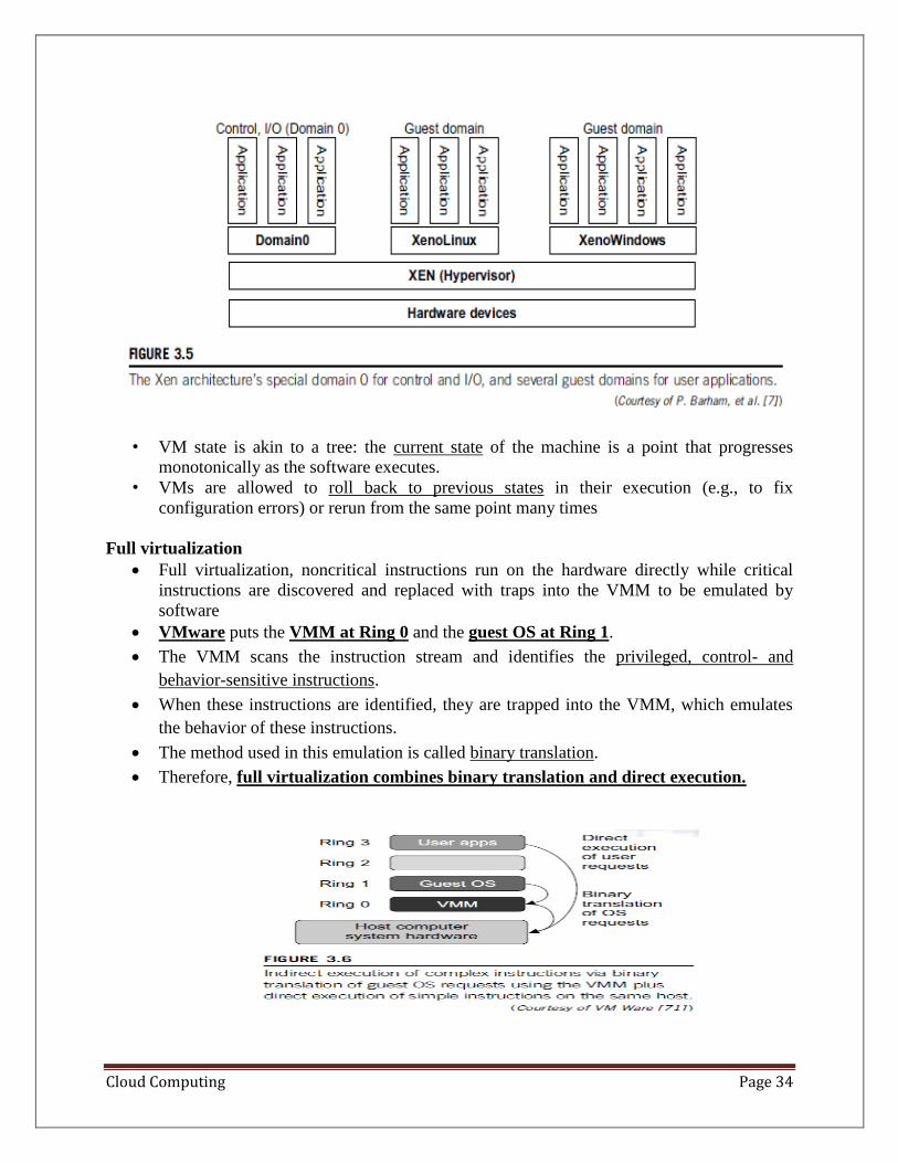
Full virtualization
• Full virtualization, noncritical instructions run on the hardware directly while critical
instructions are discovered and replaced with traps into the VMM to be emulated by
software
• VMware puts the VMM at Ring 0 and the guest OS at Ring 1.
• The VMM scans the instruction stream and identifies the privileged, control- and
behavior-sensitive instructions.
• When these instructions are identified, they are trapped into the VMM, which emulates
the behavior of these instructions.
• The method used in this emulation is called binary translation.
• Therefore, full virtualization combines binary translation and direct execution.
Cloud Computing Page 35
Para-Virtualization
• Para-virtualization needs to modify the guest operating systems
• A para-virtualized VM provides special APIs requiring substantial OS modifications in
user applications
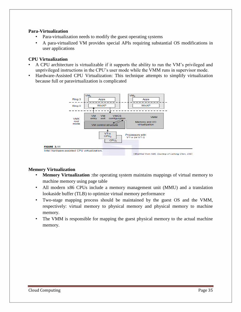
CPU Virtualization
• A CPU architecture is virtualizable if it supports the ability to run the VM’s privileged and
unprivileged instructions in the CPU’s user mode while the VMM runs in supervisor mode.
• Hardware-Assisted CPU Virtualization: This technique attempts to simplify virtualization
because full or paravirtualization is complicated
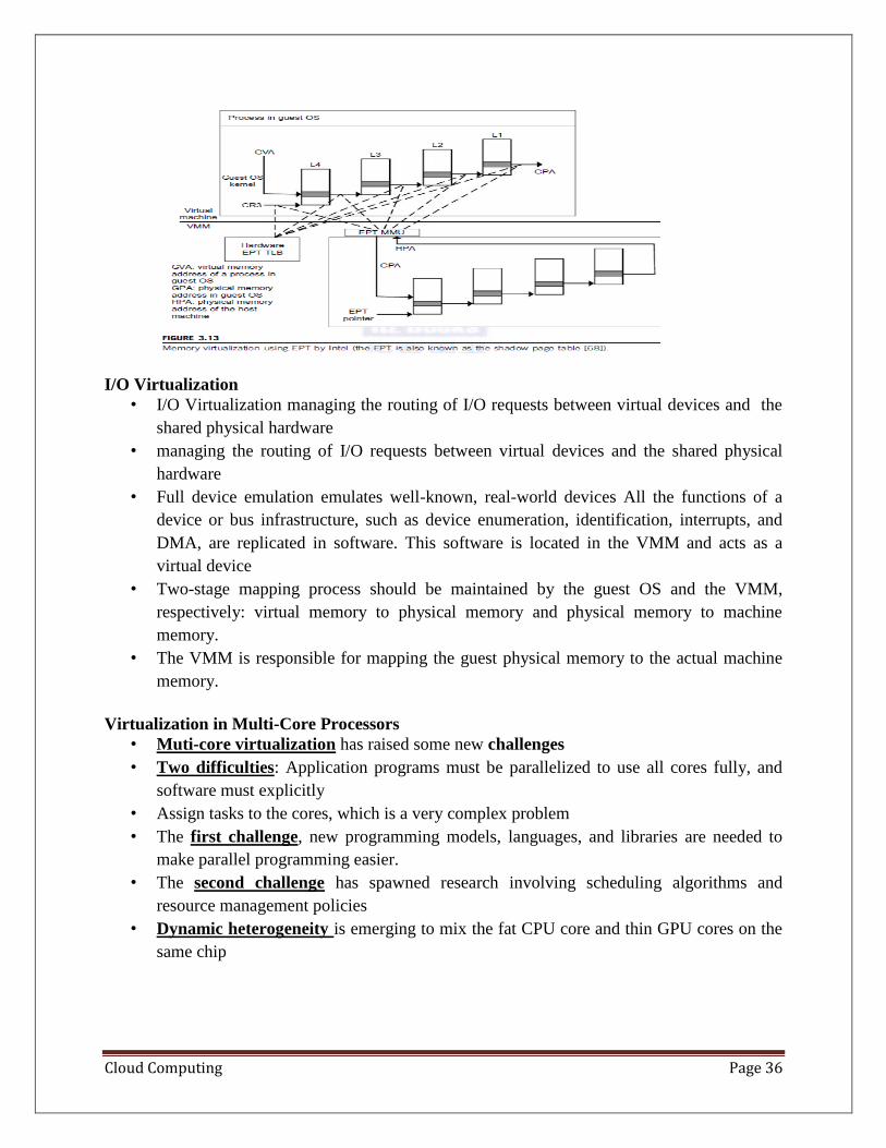
Memory Virtualization
• Memory Virtualization :the operating system maintains mappings of virtual memory to
machine memory using page table
• All modern x86 CPUs include a memory management unit (MMU) and a translation
lookaside buffer (TLB) to optimize virtual memory performance
• Two-stage mapping process should be maintained by the guest OS and the VMM,
respectively: virtual memory to physical memory and physical memory to machine
memory.
• The VMM is responsible for mapping the guest physical memory to the actual machine
memory.
Cloud Computing Page 36
I/O Virtualization
• I/O Virtualization managing the routing of I/O requests between virtual devices and the
shared physical hardware
• managing the routing of I/O requests between virtual devices and the shared physical
hardware
• Full device emulation emulates well-known, real-world devices All the functions of a
device or bus infrastructure, such as device enumeration, identification, interrupts, and
DMA, are replicated in software. This software is located in the VMM and acts as a
virtual device
• Two-stage mapping process should be maintained by the guest OS and the VMM,
respectively: virtual memory to physical memory and physical memory to machine
memory.
• The VMM is responsible for mapping the guest physical memory to the actual machine
memory.
Virtualization in Multi-Core Processors
• Muti-core virtualization has raised some new challenges
• Two difficulties: Application programs must be parallelized to use all cores fully, and
software must explicitly
• Assign tasks to the cores, which is a very complex problem
• The first challenge, new programming models, languages, and libraries are needed to
make parallel programming easier.
• The second challenge has spawned research involving scheduling algorithms and
resource management policies
• Dynamic heterogeneity is emerging to mix the fat CPU core and thin GPU cores on the
same chip
Cloud Computing Page 37
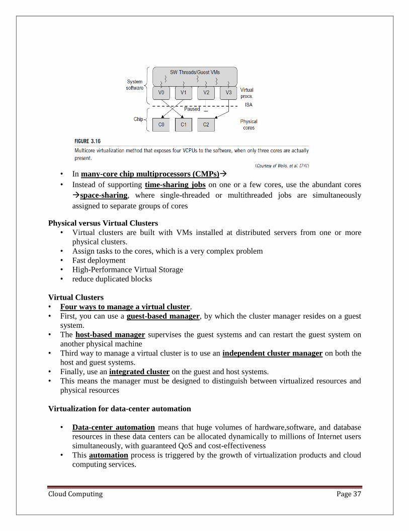
• In many-core chip multiprocessors (CMPs)→
• Instead of supporting time-sharing jobs on one or a few cores, use the abundant cores
→space-sharing, where single-threaded or multithreaded jobs are simultaneously
assigned to separate groups of cores
Physical versus Virtual Clusters
• Virtual clusters are built with VMs installed at distributed servers from one or more
physical clusters.
• Assign tasks to the cores, which is a very complex problem
• Fast deployment
• High-Performance Virtual Storage
• reduce duplicated blocks
Virtual Clusters
• Four ways to manage a virtual cluster.
• First, you can use a guest-based manager, by which the cluster manager resides on a guest
system.
• The host-based manager supervises the guest systems and can restart the guest system on
another physical machine
• Third way to manage a virtual cluster is to use an independent cluster manager on both the
host and guest systems.
• Finally, use an integrated cluster on the guest and host systems.
• This means the manager must be designed to distinguish between virtualized resources and
physical resources
Virtualization for data-center automation
• Data-center automation means that huge volumes of hardware,software, and database
resources in these data centers can be allocated dynamically to millions of Internet users
simultaneously, with guaranteed QoS and cost-effectiveness
• This automation process is triggered by the growth of virtualization products and cloud
computing services.
Cloud Computing Page 38
• The latest virtualization development highlights high availability (HA), backup services,
workload balancing, and further increases in client bases.
Server Consolidation in Data Centers
• heterogeneous workloads -chatty workloads and noninteractive workloads
• Server consolidation is an approach to improve the low utility ratio of hardware
resources by reducing the number of physical servers
Virtual Storage Management
• storage virtualization has a different meaning in a system virtualization environment
• system virtualization, virtual storage includes the storage managed by VMMs
• and guest OSes data stored in this environment
• can be classified into two categories: VM images and application data.
Cloud OS for Virtualized Data Centers
• Data centers must be virtualized to serve as cloud providers
• Eucalyptus for Virtual Networking of Private Cloud :
• Eucalyptus is an open source software system intended mainly for supporting
Infrastructure as a Service (IaaS) clouds
• The system primarily supports virtual networking and the management of VMs;
• virtual storage is not supported.
• Its purpose is to build private clouds
• three resource managers
o Instance Manager
o Group Manager
o Cloud Manager

Cloud Computing Page 39
UNIT -3 Introduction to Cloud Computing
• Cloud computing allowing access to large amounts of computing power in a fully
virtualized manner, by aggregating resources and offering a single system view
• Cloud computing has been coined as an umbrella term to describe a category of
sophisticated on-demand computing services initially offered by commercial providers,
such as Amazon, Google, and Microsoft.
• The main principle behind this model is offering computing, storage, and software “as a
service
• Cloud is a parallel and distributed computing system consisting of a collection of inter-
connected and virtualised computers that are dynamically provisioned
• The National Institute of Standards and Technology (NIST) characterizes cloud
computing as “. . . a pay-per-use model for enabling available, convenient, on-demand
network access to a shared pool of configurable computing resources
Common characteristics a cloud should have:
• pay-per-use (no ongoing commitment, utility prices);
• elastic capacity and the illusion of infinite resources;
• self-service interface; and
• resources that are abstracted or virtualised.
•
ROOTS OF CLOUD COMPUTING
• Autonomic Computing: seeks to improve systems by decreasing human involvement in
their operation
• Autonomic, or self-managing, systems rely on monitoring probes and gauges (sensors),
on an adaptation engine (autonomic manager) for computing optimizations based on
monitoring data, and on effectors to carry out changes on the system.
• IBM’s Autonomic Computing Initiative - four properties of autonomic systems: self-
configuration, selfoptimization, self-healing, and self-protection.
• Reference model for autonomic control loops of autonomic managers, called MAPE-K
(Monitor Analyze Plan Execute—Knowledge)
Cloud Computing Page 40
LAYERS AND TYPES OF CLOUDS
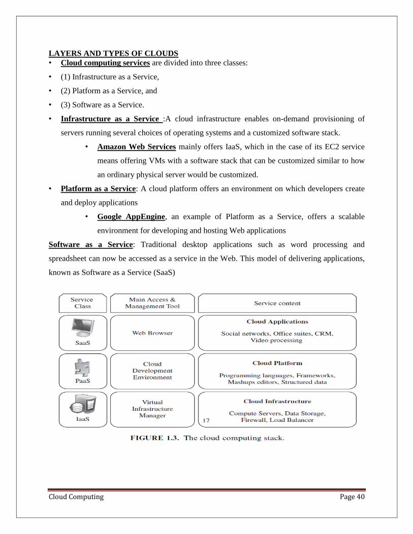
• Cloud computing services are divided into three classes:
• (1) Infrastructure as a Service,
• (2) Platform as a Service, and
• (3) Software as a Service.
• Infrastructure as a Service :A cloud infrastructure enables on-demand provisioning of
servers running several choices of operating systems and a customized software stack.
• Amazon Web Services mainly offers IaaS, which in the case of its EC2 service
means offering VMs with a software stack that can be customized similar to how
an ordinary physical server would be customized.
• Platform as a Service: A cloud platform offers an environment on which developers create
and deploy applications
• Google AppEngine, an example of Platform as a Service, offers a scalable
environment for developing and hosting Web applications
Software as a Service: Traditional desktop applications such as word processing and
spreadsheet can now be accessed as a service in the Web. This model of delivering applications,
known as Software as a Service (SaaS)
Cloud Computing Page 41
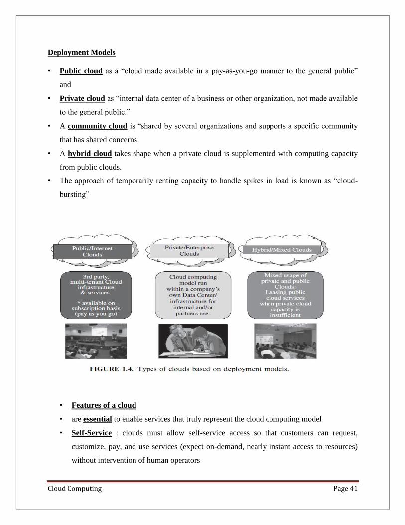
Deployment Models
• Public cloud as a “cloud made available in a pay-as-you-go manner to the general public”
and
• Private cloud as “internal data center of a business or other organization, not made available
to the general public.”
• A community cloud is “shared by several organizations and supports a specific community
that has shared concerns
• A hybrid cloud takes shape when a private cloud is supplemented with computing capacity
from public clouds.
• The approach of temporarily renting capacity to handle spikes in load is known as “cloud-
bursting”
• Features of a cloud
• are essential to enable services that truly represent the cloud computing model
• Self-Service : clouds must allow self-service access so that customers can request,
customize, pay, and use services (expect on-demand, nearly instant access to resources)
without intervention of human operators
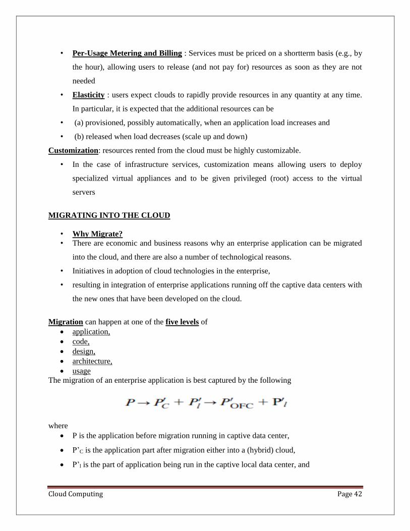
Cloud Computing Page 42
• Per-Usage Metering and Billing : Services must be priced on a shortterm basis (e.g., by
the hour), allowing users to release (and not pay for) resources as soon as they are not
needed
• Elasticity : users expect clouds to rapidly provide resources in any quantity at any time.
In particular, it is expected that the additional resources can be
• (a) provisioned, possibly automatically, when an application load increases and
• (b) released when load decreases (scale up and down)
Customization: resources rented from the cloud must be highly customizable.
• In the case of infrastructure services, customization means allowing users to deploy
specialized virtual appliances and to be given privileged (root) access to the virtual
servers
MIGRATING INTO THE CLOUD
• Why Migrate?
• There are economic and business reasons why an enterprise application can be migrated
into the cloud, and there are also a number of technological reasons.
• Initiatives in adoption of cloud technologies in the enterprise,
• resulting in integration of enterprise applications running off the captive data centers with
the new ones that have been developed on the cloud.
Migration can happen at one of the five levels of
• application,
• code,
• design,
• architecture,
• usage
The migration of an enterprise application is best captured by the following
where
• P is the application before migration running in captive data center,
• P’C is the application part after migration either into a (hybrid) cloud,
• P’l is the part of application being run in the captive local data center, and
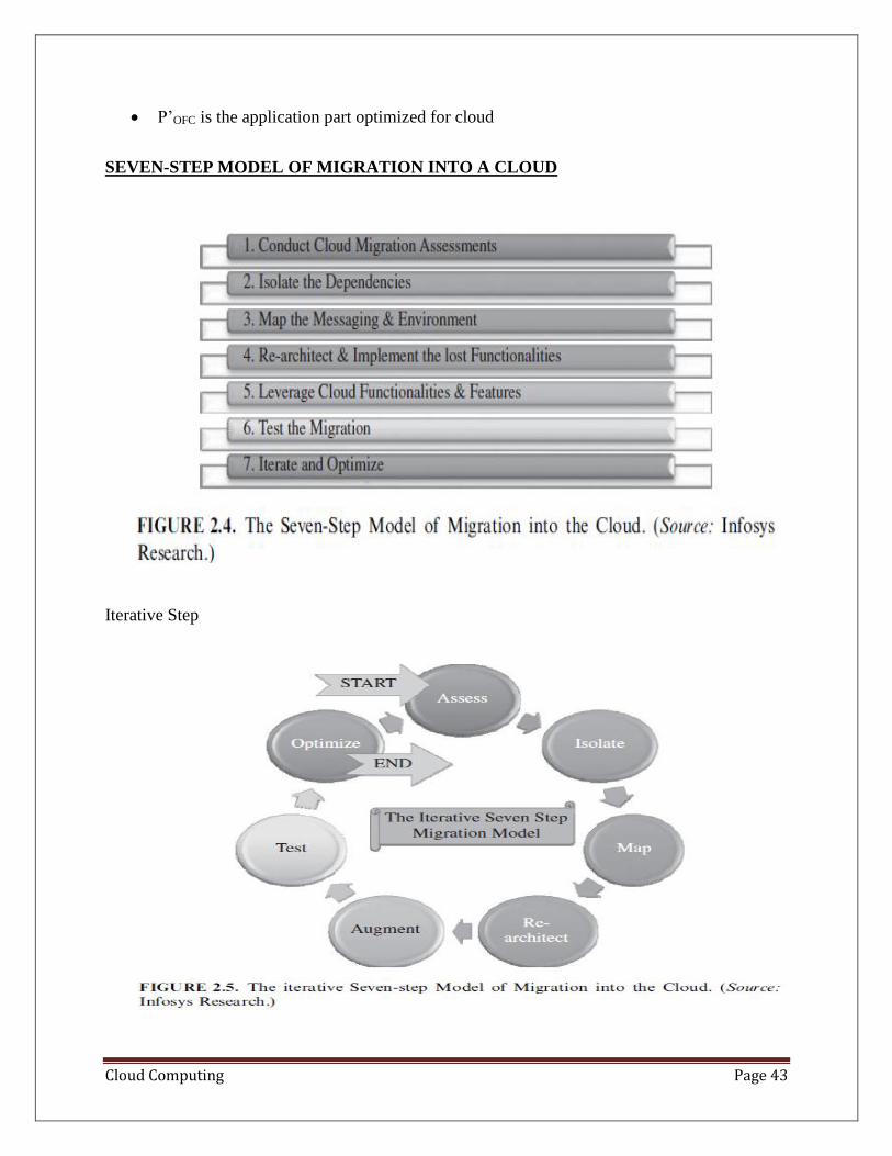
Cloud Computing Page 43
• P’OFC is the application part optimized for cloud
SEVEN-STEP MODEL OF MIGRATION INTO A CLOUD
Iterative Step
Cloud Computing Page 44
Migration Risks and Mitigation
• The biggest challenge to any cloud migration project is how effectively the migration
risks are identified and mitigated.
• Migration risks for migrating into the cloud fall under two broad categories:
• the general migration risks
• the security-related migration risks
• several issues identifying all possible production level deviants:
– the business continuity and disaster recovery in the world of cloud computing
service;
– the compliance with standards and governance issues; the IP and licensing issues;
– the quality of service (QoS) parameters as well as the corresponding SLAs
committed to;
– the ownership, transfer, and storage of data in the application;
– the portability and interoperability issues which could help mitigate potential
vendor lock-ins;
On the security front - as addressed in the guideline document published by the Cloud
Security Alliance.
– Issues include
– security at various levels of the enterprise application as applicable on the cloud
in addition to issues of trust and issues of privacy.
– There are several legal compliances that a migration strategy and implementation
has to fulfill,
– including obtaining the right execution logs as well as retaining the rights to all
audit trails at a detailed level
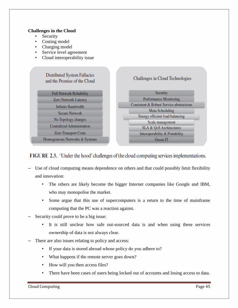
Cloud Computing Page 45
Challenges in the Cloud
• Security
• Costing model
• Charging model
• Service level agreement
• Cloud interoperability issue
– Use of cloud computing means dependence on others and that could possibly limit flexibility
and innovation:
• The others are likely become the bigger Internet companies like Google and IBM,
who may monopolise the market.
• Some argue that this use of supercomputers is a return to the time of mainframe
computing that the PC was a reaction against.
– Security could prove to be a big issue:
• It is still unclear how safe out-sourced data is and when using these services
ownership of data is not always clear.
– There are also issues relating to policy and access:
• If your data is stored abroad whose policy do you adhere to?
• What happens if the remote server goes down?
• How will you then access files?
• There have been cases of users being locked out of accounts and losing access to data.
Cloud Computing Page 46
UNIT -4
INFRASTRUCTURE AS A SERVICE PROVIDERS (IAAS)
• Public Infrastructure as a Service providers commonly offer virtual servers containing
one or more CPUs, OS, software stack, storage space and communication facilities
• The most relevant features are:
• (i) geographic distribution of data centers;
• (ii) variety of user interfaces and APIs to access the system;
• (iii) specialized components and services that aid particular applications (e.g.,
loadbalancers,)
• (iv) choice of virtualization platform and operating systems;
• (v) different billing methods and period
Geographic Presence: To improve availability and responsiveness, a provider of worldwide
services would typically build several data centers distributed around the world.
• Availability zones are “distinct locations that are engineered to be
insulated from failures in other availability zones and provide inexpensive,
low-latency network connectivity to other availability zones in the same
region.”
• User Interfaces and Access to Servers.
• Ideally, a public IaaS provider must provide multiple access means to its cloud, thus
catering for various usersand their preferences.
• Different types of user interfaces (UI) provide different levels of abstraction, the most
common being
• graphical user interfaces (GUI),
• command-line tools (CLI), and
• Web service (WS) APIs.
Advance Reservation of Capacity.
Cloud Computing Page 47
• Advance reservations allow users to request for an IaaS provider to reserve resources
for a specific time frame in the future, thus ensuring that cloud resources will be available
at that time
• Amazon Reserved Instances is a form of advance reservation of capacity,
allowing users to pay a fixed amount of money in advance to guarantee resource
availability
• Automatic Scaling and Load Balancing.
• As mentioned earlier in this chapter, elasticity is a key characteristic of the cloud
computing model.
• Applications often need to scale up and down to meet varying load conditions.
• Service-Level Agreement.
• Service-level agreements (SLAs) are offered by IaaS providers to express their
commitment to delivery of a certain QoS.
• To customers it serves as a warranty.
• Amazon EC2 states that “if the annual uptime Percentage for a customer drops
below 99.95% for the service year, that customer is eligible to receive a service
credit equal to 10% of their bill.3”
• Hypervisor and Operating System Choice:
– Traditionally, IaaS offerings have been based on heavily customized open-source
Xen deployments.
– IaaS providers needed expertise in Linux, networking, virtualization, metering,
resource management, and many other low-level aspects to successfully deploy
and maintain their cloud offerings.
Public Cloud and Infrastructure Services
• Public cloud or external cloud
• describes cloud computing - resources are dynamically provisioned via publicly
accessible Web applications/Web services (SOAP or RESTful interfaces) from an off-site
third-party provider,
• who shares resources and bills on a fine-grained utility computing basis,
Cloud Computing Page 48
• the user pays only for the capacity of the provisioned resources at a particular time
Amazon Elastic Compute Cloud (EC2) is an IaaS service that provides elastic compute
capacity in the cloud
Private Cloud and Infrastructure Services
• A private cloud aims at providing public cloud functionality, but on private resources,
while maintaining control over an organization’s data and resources to meet security and
governance’s requirements in an organization.
• Private clouds exhibit the following characteristics:
– Allow service provisioning and compute capability for an organization’s users in
a self-service manner.
– Automate and provide well-managed virtualized environments.
– Optimize computing resources, and servers’ utilization.
– Support specific workloads.
• Examples are Eucalyptus and OpenNebula
“Hybrid cloud”
• in which a combination of private/internal and external cloud resources exist together by
enabling outsourcing of noncritical services and functions in public cloud and keeping the
critical ones internal
• Release resources from a public cloud and to handle sudden demand usage, which is
called “cloud bursting
Cloud and Virtualization Standardization Efforts
• Standardization is important to ensure interoperability between
• virtualization mangement vendors,
• the virtual machines produced by each one of them,
• and cloud computing
• Distributed Management Task Force(DMTF)
• initiated the VMAN (Virtualization Management Initiative),
• delivers broadly supported interoperability and portability standards for managing the
virtual computing lifecycle.
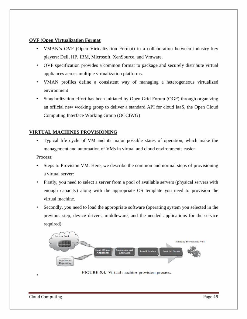
Cloud Computing Page 49
OVF (Open Virtualization Format
• VMAN’s OVF (Open Virtualization Format) in a collaboration between industry key
players: Dell, HP, IBM, Microsoft, XenSource, and Vmware.
• OVF specification provides a common format to package and securely distribute virtual
appliances across multiple virtualization platforms.
• VMAN profiles define a consistent way of managing a heterogeneous virtualized
environment
• Standardization effort has been initiated by Open Grid Forum (OGF) through organizing
an official new working group to deliver a standard API for cloud IaaS, the Open Cloud
Computing Interface Working Group (OCCIWG)
VIRTUAL MACHINES PROVISIONING
• Typical life cycle of VM and its major possible states of operation, which make the
management and automation of VMs in virtual and cloud environments easier
Process:
• Steps to Provision VM. Here, we describe the common and normal steps of provisioning
a virtual server:
• Firstly, you need to select a server from a pool of available servers (physical servers with
enough capacity) along with the appropriate OS template you need to provision the
virtual machine.
• Secondly, you need to load the appropriate software (operating system you selected in the
previous step, device drivers, middleware, and the needed applications for the service
required).
•
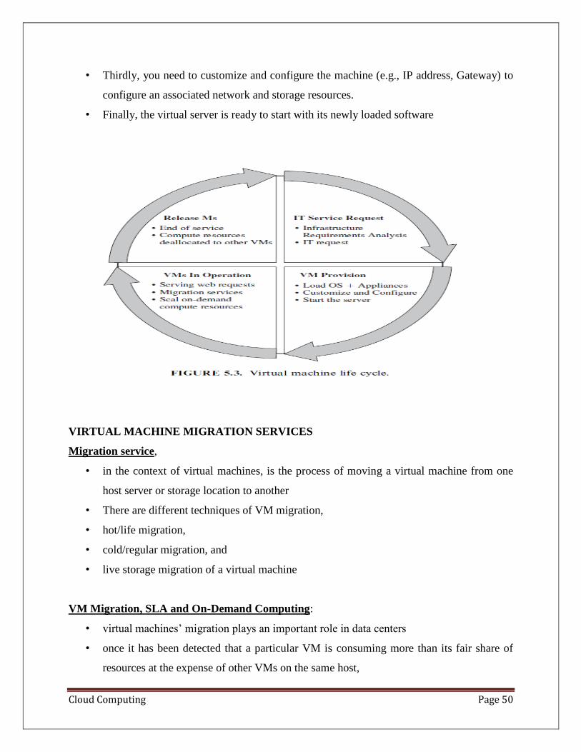
Cloud Computing Page 50
• Thirdly, you need to customize and configure the machine (e.g., IP address, Gateway) to
configure an associated network and storage resources.
• Finally, the virtual server is ready to start with its newly loaded software
VIRTUAL MACHINE MIGRATION SERVICES
Migration service,
• in the context of virtual machines, is the process of moving a virtual machine from one
host server or storage location to another
• There are different techniques of VM migration,
• hot/life migration,
• cold/regular migration, and
• live storage migration of a virtual machine
VM Migration, SLA and On-Demand Computing:
• virtual machines’ migration plays an important role in data centers
• once it has been detected that a particular VM is consuming more than its fair share of
resources at the expense of other VMs on the same host,
Cloud Computing Page 51
• it will be eligible, for this machine, to either be moved to another underutilized host or
assign more resources for it
• There should be an integration between virtualization’s management tools (with its
migrations and performance’s monitoring capabilities), and SLA’s management tools to
achieve balance in resources by migrating and monitoring the workloads, and
accordingly, meeting the SLA
Migration of Virtual Machines to Alternate Platforms
• Advantages of having facility in data center’s technologies is
• to have the ability to migrate virtual machines from one platform to another
• For example, the VMware converter that handles migrations between ESX hosts;
• the VMware server; and the VMware workstation.
• The VMware converter can also import from other virtualization platforms, such as
Microsoft virtual server machines
Deployment Scenario:
• ConVirt deployment consists of at least one ConVirt workstation,
• whereConVirt is installed and ran, which provides the main console for managing the
VM life cycle, managing images, provisioning new VMs, monitoring machine resources,
and so on.
• There are two essential deployment scenarios for ConVirt:
• A, basic configuration in which the Xen or KVM virtualization platform is on the local
machine, where ConVirt is already installed; B,
• An advanced configuration in which the Xen or KVM is on one or more remote servers.
Installation. The installation process involves the following:
• Installing ConVirt on at least one computer.
• Preparing each managed server to be managed by ConVirt.
• We have two managing servers with the following Ips
• (managed server 1, IP:172.16.2.22; and
• managed server 2, IP:172.16.2.25) as shown in the deployment diagram
Cloud Computing Page 52
Environment, Software, and Hardware. ConVirt 1.1, Linux Ubuntu 8.10, three machines, Dell
core 2 due processor, 4G RAM.
• Adding Managed Servers and Provisioning VM.
• Once the installation is done and you are ready to manage your virtual infrastructure, then
you can start the ConVirt management console :
• Select any of servers’ pools existing (QA Lab in our scenario) and on its context menu,
select “Add Server.”
• You will be faced with a message asking about the virtualization platform you want to
manage (Xen or KVM), as shown in Figure
• Choose KVM, and then enter the managed server information and credentials (IP,
username, and password) as shown in Figure
• Once the server is synchronized and authenticated with the management console, it will
appear in the left pane/of the ConVirt,
• Live Migration Effect on a Running Web Server.
• Clark et al. did evaluate the above migration on an Apache 1.3 Web server; this served
static content at a high rate, as illustrated in Figure 5.6.
• The throughput is achieved when continuously serving a single 512-kB file to a set of one
hundred concurrent clients.
• This simple example demonstrates that a highly loaded server can be migrated with both
controlled impact on live services and a short downtime
• VMware Vmotion.
• This allows users to
• (a) automatically optimize and allocate an entire pool of resources for maximum
hardware utilization, flexibility, and availability and
• (b) perform hardware’s maintenance without scheduled downtime along with migrating
virtual machines away from failing or underperforming servers
• Citrix XenServerXenMotion.
Cloud Computing Page 53
• This is a nice feature of the Citrix XenServer product, inherited from the Xen live migrate
utility, which provides the IT administrator with the facility to move a running VM from
one XenServer to another in the same pool without interrupting the service
Regular/Cold Migration.
Cold migration is the migration of a powered-off virtual machine.
• Main differences between live migration and cold migration are that
• 1) live migration needs a shared storage for virtual machines in the server’s pool, but
cold migration does not;
• 2) live migration for a virtual machine between two hosts, there would be certain CPU
compatibility checks to be applied; while in cold migration this checks do not apply
• The cold migration process (VMware ) can be summarized as follows:
• The configuration files, including the NVRAM file (BIOS settings), log files, as
well as the disks of the virtual machine, are moved from the source host to the
destination host’s associated storage area.
• The virtual machine is registered with the new host.
• After the migration is completed, the old version of the virtual machine is deleted
from the source host.
Live Storage Migration of Virtual Machine.
• This kind of migration constitutes moving the virtual disks or configuration file of a
running virtual machine to a new data store without any interruption in the availability of
the virtual machine’s service
Aneka
• Manjrasoft Aneka is a .NET-based platform and framework designed for building and
deploying distributed applications on clouds.
• It provides a set of APIs for transparently exploiting distributed resources and expressing
the business logic of applications by using the preferred programming abstractions.
• Aneka also provides support for deploying and managing clouds.
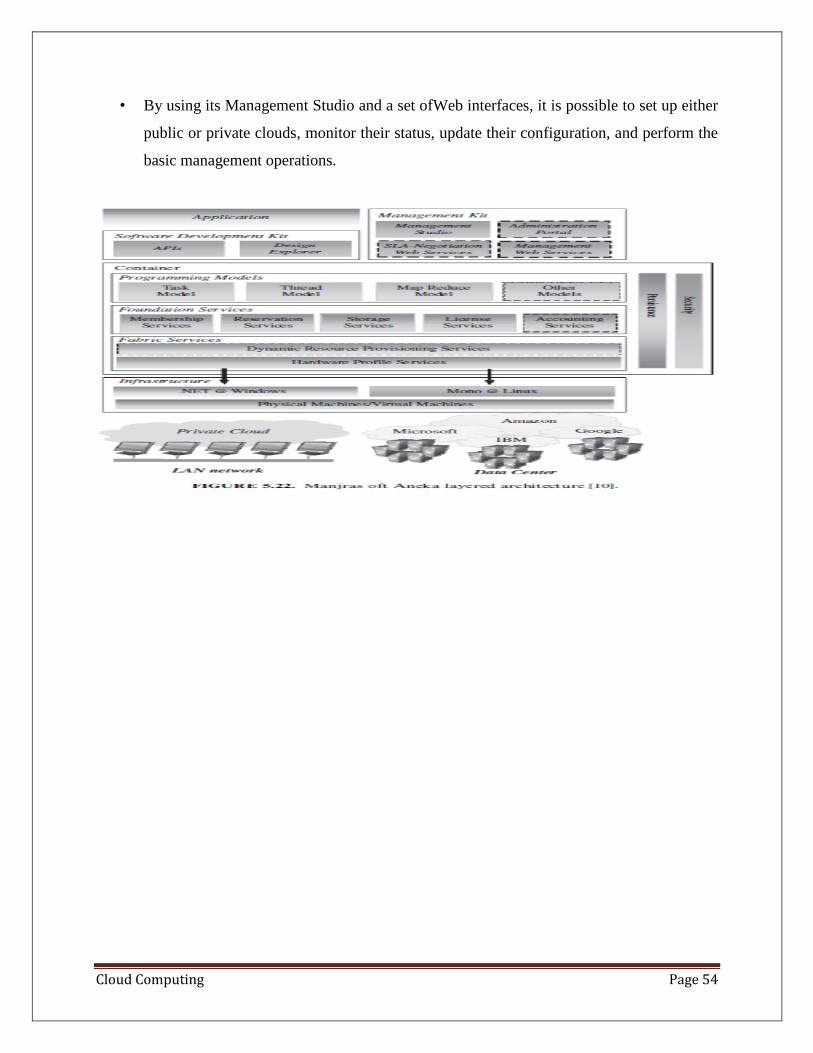
Cloud Computing Page 54
• By using its Management Studio and a set ofWeb interfaces, it is possible to set up either
public or private clouds, monitor their status, update their configuration, and perform the
basic management operations.
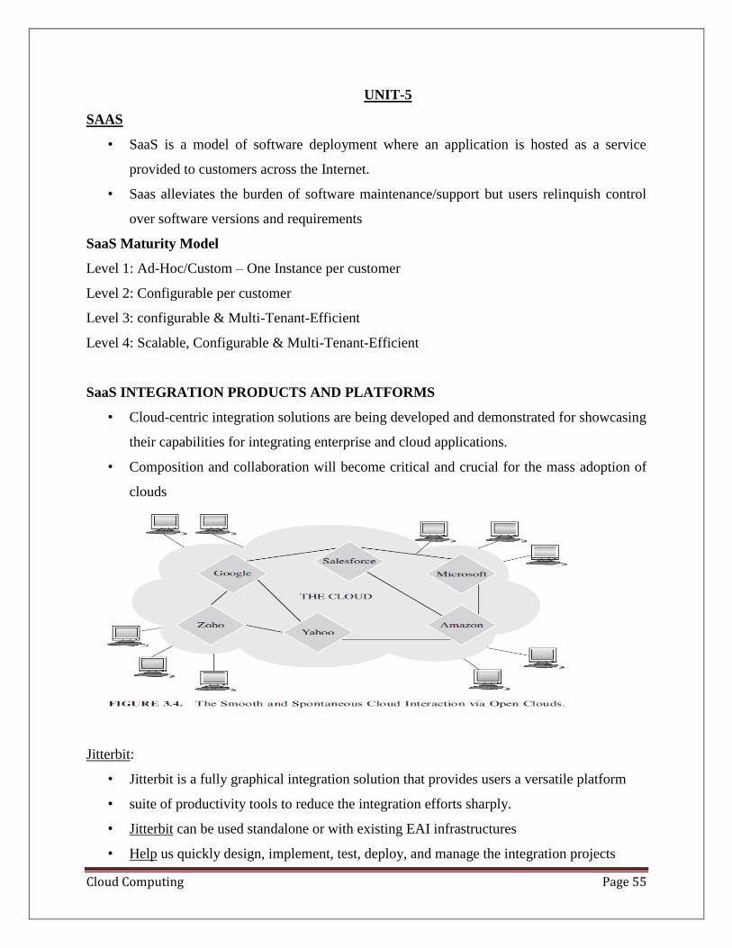
Cloud Computing Page 55
UNIT-5
SAAS
• SaaS is a model of software deployment where an application is hosted as a service
provided to customers across the Internet.
• Saas alleviates the burden of software maintenance/support but users relinquish control
over software versions and requirements
SaaS Maturity Model
Level 1: Ad-Hoc/Custom – One Instance per customer
Level 2: Configurable per customer
Level 3: configurable & Multi-Tenant-Efficient
Level 4: Scalable, Configurable & Multi-Tenant-Efficient
SaaS INTEGRATION PRODUCTS AND PLATFORMS
• Cloud-centric integration solutions are being developed and demonstrated for showcasing
their capabilities for integrating enterprise and cloud applications.
• Composition and collaboration will become critical and crucial for the mass adoption of
clouds
Jitterbit:
• Jitterbit is a fully graphical integration solution that provides users a versatile platform
• suite of productivity tools to reduce the integration efforts sharply.
• Jitterbit can be used standalone or with existing EAI infrastructures
• Help us quickly design, implement, test, deploy, and manage the integration projects
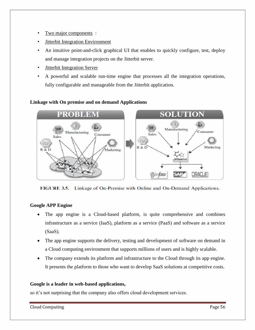
Cloud Computing Page 56
• Two major components :
• Jitterbit Integration Environment
• An intuitive point-and-click graphical UI that enables to quickly configure, test, deploy
and manage integration projects on the Jitterbit server.
• Jitterbit Integration Server
• A powerful and scalable run-time engine that processes all the integration operations,
fully configurable and manageable from the Jitterbit application.
Linkage with On premise and on demand Applications
Google APP Engine
• The app engine is a Cloud-based platform, is quite comprehensive and combines
infrastructure as a service (IaaS), platform as a service (PaaS) and software as a service
(SaaS).
• The app engine supports the delivery, testing and development of software on demand in
a Cloud computing environment that supports millions of users and is highly scalable.
• The company extends its platform and infrastructure to the Cloud through its app engine.
It presents the platform to those who want to develop SaaS solutions at competitive costs.
Google is a leader in web-based applications,
so it’s not surprising that the company also offers cloud development services.
Cloud Computing Page 57
• These services come in the form of the Google App Engine, which enables developers to
build their own web applications utilizing the same infrastructure that powers Google’s
powerful applications.
• The Google App Engine provides a fully integrated application environment. Using
Google’s development tools and computing cloud, App Engine applications are easy to
build, easy to maintain, and easy to scale. All you have to do
Features of App Engine
• These are covered by the depreciation policy and the service-level agreement of the app
engine. Any changes made to such a feature are backward-compatible and
implementation of such a feature is usually stable. These include data storage, retrieval,
and search; communications; process management; computation; app configuration and
management.
• Data storage, retrieval, and search include features such as HRD migration tool, Google Cloud
SQL, logs, datastore, dedicated Memcache, blobstore, Memcache and search.
• Communications include features such as XMPP. channel, URL fetch, mail, and Google Cloud
Endpoints.
• Process management includes features like scheduled tasks and task queue
• Computation includes images.
• App management and configuration cover app identity, users, capabilities, traffic splitting,
modules, SSL for custom domains, modules, remote access, and multitenancy
Centralizing email Communications
• The key here is to enable anywhere/anytime access to email.
• Precloud computing, your email access was via a single computer, which also stored all
your email messages. For this purpose, you probably used a program like Microsoft
Outlook or Outlook Express, installed on your home computer.
• To check your home email from work, it took a bit of juggling and perhaps the use of
your ISP’s email access web page. That web page was never in sync with the messages
Cloud Computing Page 58
on your home PC, of course, which is just the start of the problems with trying to
communicate in this fashion.
• A better approach is to use a web-based email service, such as Google’s Gmail
(mail.google.com), Microsoft’s Windows Live Hotmail (mail.live.com), or Yahoo! Mail
(mail.yahoo.com). These services place your email inbox in the cloud; you can access it
from any computer connected to the Internet.
Collaborating via Web-Based Communication Tools
GMAIL
• Gmail offers a few unique features that set it apart from the web-based email crowd.
• First, Gmail doesn’t use folders. With Gmail you can’t organize your mail into folders, as
you can with the other services.
• Instead, Gmail pushes the search paradigm as the way to find the messages you want—
not a surprise, given Google’s search-centric business model.
• Gmail does, however, let you “tag” each message with one or more labels. This has the
effect of creating virtual folders, as you can search and sort your messages by any of their
labels.
• In addition, Gmail groups together related email messages in what Google calls
conversations
Yahoo! Mail Yahoo! Mail (mail.yahoo.com)
• is another web mail service, provided by the popular Yahoo! search site.
• The basic Yahoo! Mail is free and can be accessed from any PC, using any web
browser.
• Yahoo! also offers a paid service called Yahoo! Mail Plus that lets you send larger
messages and offers offline access to your messages via POP email clients
Web Mail Services
• AOL Mail (mail.aol.com)
• BigString (www.bigstring.com) E
• xcite Mail (mail.excite.com)
• FlashMail (www.flashmail.com)
Cloud Computing Page 59
• GMX Mail (www.gmx.com)
• Inbox.com (www.inbox.com)
• Lycos Mail (mail.lycos.com)
• Mail.com (www.mail.com)
• Zoho Mail (zoho.mail.com)
Data Security
• Information in a cloud environment has much more dynamism and fluidity than
information that is static on a desktop or in a network folder
• Nature of cloud computing dictates that data are fluid objects, accessible froma multitude
of nodes and geographic locations and, as such, must have a datasecurity methodology
that takes this into account while ensuring that this fluidity is not compromised
• The idea of content-centric or information-centric protection, being an inherent part of a
data object is a development out of the idea of the “de-perimerization” of the enterprise.
• This idea was put forward by a group of Chief Information Officers (CIOs) who formed
an organization called the Jericho Forum
CLOUD COMPUTING AND IDENTITY
Digital identity
• holds the key to flexible data security within a cloud Environment
• A digital identity represents who we are and how we interact with others on-line.
• Access, identity, and risk are three variables that can become inherently connected
when applied to the security of data, because access and risk are directly proportional:
As access increases, so then risk to the security of the data increases.
• Access controlled by identifying the actor attempting the access is the most logical
manner of performing this operation.
• Ultimately, digital identity holds the key to securing data, if that digital identity can be
programmatically linked to security policies controlling the post-access usage of data.
Identity, Reputation, and Trust
Cloud Computing Page 60
• Reputation is a real-world commodity; that is a basic requirement of human-to-human
relationships
• Our basic societal communication structure is built upon the idea of reputation and trust.
• Reputation and its counter value, trust, is easily transferable to a digital realm:
o eBay, for example, having partly built a successful business model on the strength
of a ratings system, builds up the reputation of its buyers and sellers through
successful (or unsuccessful) transactions.
• These types of reputation systems can be extremely useful when used with a digital
identity.
• They can be used to associate varying levels of trust with that identity, which in turn can
be used to define the level (granular variations) of security policy applied to data
resources that the individual wishes to access
User-Centric Identity:
• Digital identities are a mechanism for identifying an individual, particularly within a cloud
environment ; identity ownership being placed upon the individual is known as user-
centric identity
• It allows users to consent and control how their identity (and the individual identifiers
making up the identity, the claims) is used.
• This reversal of ownership away from centrally managed identity platforms (enterprise-
centric) has many advantages.
• This includes the potential to improve the privacy aspects of a digital identity, by giving an
individual the ability to apply permission policies based on their identity and to control
which aspects of that identity are divulged
• An identity may be controllable by the end user, to the extent that the user can then
decide what information is given to the party relying on the identity
Information Card:
• Information cards permit a user to present to a Web site or other service (relying party)
one or more claims, in the form of a software token, which may be used to uniquely
identify that user.
Cloud Computing Page 61
• They can be used in place of user name/ passwords, digital certificates, and other
identification systems, when user identity needs to be established to control access to a
Web site or other resource, or to permit digital signing
Information cards are part of an identity meta-system consisting of:
• 1. Identity providers (IdP), who provision and manage information cards,with specific
claims, to users.
• 2. Users who own and utilize the cards to gain access to Web sites and other resources
that support information cards.
• An identity selector/service, which is a piece of software on the user’s desktop or in the
cloud that allows a user to select and manage their cards.
• 4. Relying parties. These are the applications, services, and so on, that can use an
information card to authenticate a person and to then authorize an action such as logging
onto a Web site, accessing a document, signing content, and so on
Each information card is associated with a set of claims which can be used toidentify the user.
These claims include identifiers such as name, email address,post code
Using Information Cards to Protect Data
• Information cards are built around a set of open standards devised by a consortium that
includes Microsoft, IBM, Novell, and so on.
• The original remit of the cards was to create a type of single sign on system for the
Internet, to help users to move away from the need to remember multiple passwords.
• However, the information card system can be used in many more ways.
• Because an information card is a type of digital identity, it can be used in the same way
that other digital identities can be used.
For example, an information card can be used to digitally sign data and content and to control
access to data and content. One of the more sophisticated uses of an information card is the
advantage given to the cards by way of the claims system.
Cloud Computing and Data Security Risk
• Cloud computing is a development that is meant to allow more open accessibility and
easier and improved data sharing.
Cloud Computing Page 62
• Data are uploaded into a cloud and stored in a data center, for access by users from that
data center; or in a more fully cloud-based model, the data themselves are created in the
cloud and stored and accessed from the cloud (again via a data center).
• The most obvious risk in this scenario is that associated with the storage of that data. A
user uploading or creating cloud-based data include those data that are stored and
maintained by a third-party cloud provider such as Google, Amazon, Microsoft, and so
on.
This action has several risks associated with it:
• Firstly, it is necessary to protect the data during upload into the data center to ensure that
the data do not get hijacked on the way into the database.
• Secondly, it is necessary to the stores the data in the data center to ensure that they are
encrypted at all times.
• Thirdly, and perhaps less obvious, the access to those data need to be controlled; this
control should also be applied to the hosting company, including the administrators of the
data center.
• In addition, an area often forgotten in the application of security to a data resource is the
protection of that resource during its use
Data security risks are compounded by the open nature of cloud computing.
• Access control becomes a much more fundamental issue in cloud-based systems because
of the accessibility of the data
• Information-centric access control (as opposed to access control lists) can help to balance
improved accessibility with risk, by associating access rules with different data objects
within an open and accessible platform, without losing the Inherent usability of that
platform
• A further area of risk associated not only with cloud computing, but also with traditional
network computing, is the use of content after access.
• The risk is potentially higher in a cloud network, for the simple reason that the
information is outside of your corporate walls
Cloud Computing Page 63
Data-centric mashupsare those
• that are used to perform business processes around data creation and dissemination—by
their very nature, can be used to hijack data, leaking sensitive information and/or
affecting integrity of that data
• Cloud computing, more than any other form of digital communication technology, has
created a need to ensure that protection is applied at the inception of the information, in a
content centric manner, ensuring that a security policy becomes an integral part of that
data throughout its life cycle.
Encryption
• is a vital component of the protection policy, but further controls over the access of that
data and on the use of the data must be met.
• In the case of mashups, the controlling of access to data resources, can help toalleviate
the security concerns by ensuring that mashup access is authenticated.
• Linking security policies, as applied to the use of content, to the access control method
offer a way of continuing protection of data, post access and throughout the life cycle;
this type of data security philosophy must be incorporated into the use of cloud
computing to alleviate security risks.