Embed Size (px)
Citation preview

Digital Navigation Implant
Digital Implant No.1
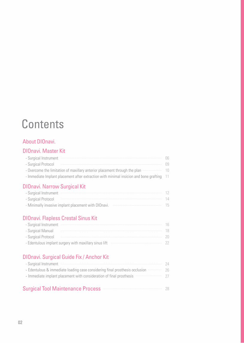
ContentsAbout DIOnavi.
DIOnavi. Master Kit- Surgical Instrument - Surgical Protocol- Overcome the limitation of maxillary anterior placement through the plan- Immediate Implant placement after extraction with minimal insicion and bone grafting
DIOnavi. Narrow Surgical Kit- Surgical Instrument- Surgical Protocol- Minimally invasive implant placement with DIOnavi.
DIOnavi. Flapless Crestal Sinus Kit- Surgical Instrument- Surgical Manual - Surgical Protocol - Edentulous implant surgery with maxillary sinus lift
DIOnavi. Surgical Guide Fix / Anchor Kit- Surgical Instrument- Edentulous & immediate loading case considering final prosthesis occlusion
- Immediate implant placement with consideration of final prosthesis
Surgical Tool Maintenance Process
02
06091011
121415
16182022
242627
28

DIOnavi. surgical instruments guarantee superior cutting force and durability.It is fully optimized for flapless surgery.
UF(II) Fixture Ø3.0 / Ø3.3 / Ø3.8 / Ø4.0 / Ø4.5 / Ø5.0 Exclusive kit for a flapless surgery
UF(II) Fixture Ø3.0 / Ø3.3
Connect Guide Fix on fixture after placing implantand insert Fix Pin after initial drilling or use Anchor Screw to fixsurgical guide in edentulous cases or free-end case
This kit supports flapless sinus surgery (Crestal approach only)
Surgical Instrument
DIOnavi. Master Kit
DIOnavi. Narrow Kit
Order Code_ UF(M) 05
Order Code_ UF 14
DIOnavi. Surgical Guide Fix/ Anchor KitOrder Code_ SGF 02
DIOnavi. Flapless Crestal Sinus KitOrder Code_ SMK 02
03

DIOnavi. Digital Implant System increases the accuracy of the implant placement through implant planning that considers both occlusion and stress diversion and it can also be useful in patient consultation with 3D simulation.
What is DIOnavi.?
Digital Navigation Implant
Implant surgery using DIOnavi. Conventional implant surgery
04
With the highest accuracy and the stability
Crown is designed first on the exact location,and then fixture is placed below, therefore the implant canwithstand the high load, and it is advantageous forabutment selection and maintenance.
It may be difficult to disperse loading which may lead to fracturedprosthetics or implant failure since it is difficult to line up the center of theimplant and the crown.
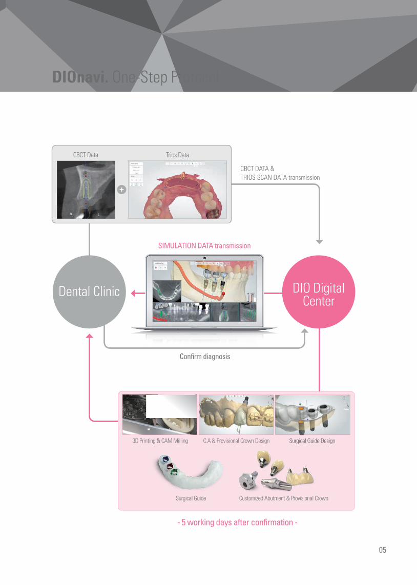
DIOnavi. One-Step Protocol
Dental Clinic DIO DigitalCenter
+
CBCT Data
3D Printing & CAM Milling C.A & Provisional Crown Design Surgical Guide Design
Customized Abutment & Provisional CrownSurgical Guide
Trios Data
05
CBCT DATA & TRIOS SCAN DATA transmission
Confirm diagnosis
SIMULATION DATA transmission
- 5 working days after confirmation -

DIOnavi. Navigation Implant
DIOnavi. Master Kit Order Code_ UF(M) 05
Initial Drill Profile Drill Implant Connector
Point Straight Drill & Drill Tube
Bone Flattening Drill
Tissue Punch Guide Drill
Drill Extension
Ratchet Wrench
Connector Extension
Abutment Profile Drill
Outstanding cutting forces and durability. Available for UF(II) System
Tap Drill
DIO IMPLANT
Final Drill
06
F 3.0
F 3.3
CE 65
08A
CE 65
08M
Ø2.5
S
Ø2.5
L
Drill Tube
GTP
5125

Tissue Punch
4 Initial DrillForms a hole (osteotomy site) on the cortical bone
1 Stable gingiva removal is possible with a fixed blade inside the tissue punch (Flapless Surgery)
Forms a hole on the bone to facilitate initial drilling
Flattens uneven alveolar bone surfaceand removes gingiva residue
Ø3.0GTP 5125
Diameter
Code
■ Product Code
D
Unit: mm
Ø2.0ISD 2005M
7
Diameter
Unit: mm
Length
5
8.510
11.51315
ISD 2007MISD 2008MISD 2010MISD 2011MISD 2013MISD 2015M*
■ Product Code
* Optional items
3 Guide Drill
Ø2.0UGD 2030M
Diameter
Unit: mm
Code
■ Product Code
Ø3.8 Ø4.0 Ø4.5 Ø5.0GPD 3805M GPD 4005M GPD 4505M GPD 5005M
Diameter
Unit: mm
Code
■ Product Code
Prevents excessive torque by expanding the cortical bone on the D1 and D2 bone6 Profile Drill
D
910.5
2 Bone Flattening Drill
UBFD 5127M
Unit: mm
Code
■ Product Code
910.5
12
Ø2.7 Ø3.0 Ø3.2 Ø3.8 Ø4.3USD 2707M USD 3007M* USD 3207M* USD 3807M* USD 4307M*
USD 3008M USD 3208M USD 3808M USD 4308M
USD 3010M USD 3210M USD 3810M USD 4310M
USD 3011M USD 3211M USD 3811M USD 4311M
USD 3013M USD 3213M USD 3813M USD 4313M
USD 3015M* USD 3215M* USD 3815M* USD 4315M*
8.5
Diameter
Unit: mm
Length
7
10
11.5
13
15
USD 2708M
USD 2710M
USD 2711M
USD 2713M
USD 2715M*
■ Product Code
* Optional items
Ø2.0
0.5
Length 5 7 8.5 10 11.5 13 15
L
*
5 Final DrillExpands the drill hole untill final drilling
D
0.5
Length 7 8.5 10 11.5 13 15
L
* *
Digital Implant No.1 DIO
07
D
7
GTP
5125
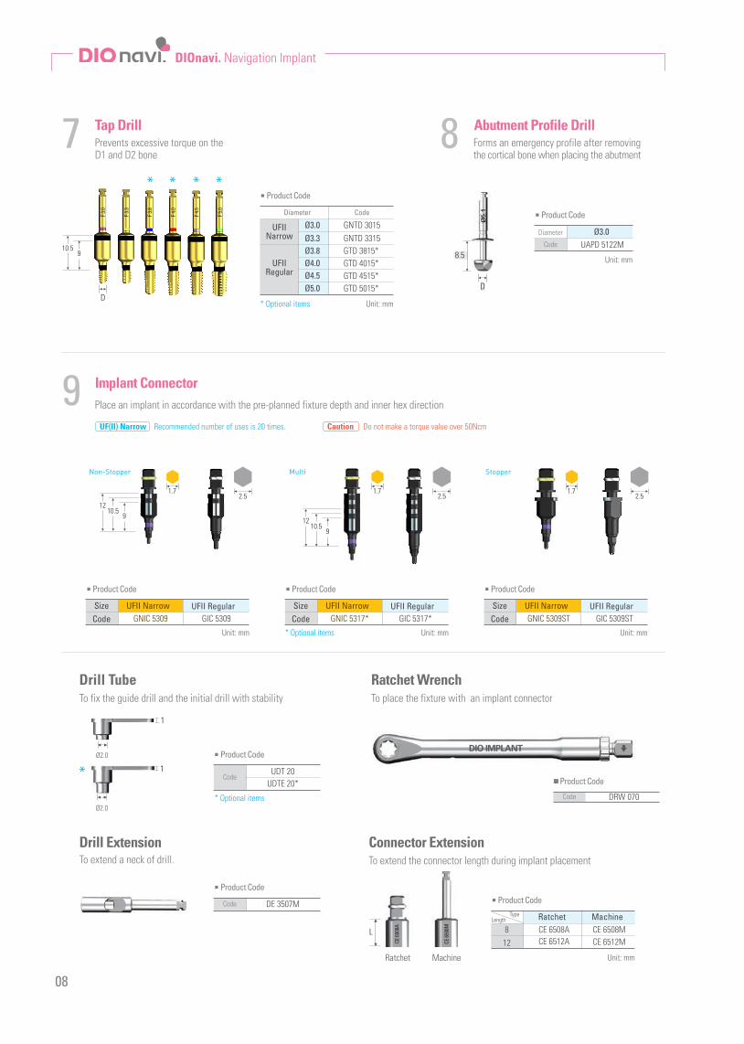
8 Abutment Profile Drill
Ø3.0UAPD 5122M
Diameter
Unit: mm
Code
■ Product Code
7 Tap DrillPrevents excessive torque on the D1 and D2 bone
Place an implant in accordance with the pre-planned fixture depth and inner hex direction
Forms an emergency profile after removing the cortical bone when placing the abutment
GNTD 3015Ø3.3
Unit: mm
Ø3.0UFIINarrow
UFIIRegular
Ø3.8Ø4.0Ø4.5Ø5.0
GNTD 3315GTD 3815*GTD 4015*GTD 4515*GTD 5015*
■ Product Code
Diameter Code
9 Implant Connector
UFII RegularGNIC 5309 GIC 5309Code
Unit: mm
Size
■ Product Code
UFII RegularGNIC 5317* GIC 5317*Code
Unit: mm
Size
■ Product Code
UFII NarrowUFII NarrowUFII Narrow UFII RegularGNIC 5309ST GIC 5309STCode
Unit: mm
Size
■ Product Code
Ratchet WrenchTo place the fixture with an implant connector
DRW 070Code
■ Product Code
Drill TubeTo fix the guide drill and the initial drill with stability
UDT 20UDTE 20*
Code
■ Product Code
Connector ExtensionTo extend the connector length during implant placement
Ratchet MachineCE 6508A CE 6508M
CE 6512M12
Type
Unit: mm
Length
8CE 6512A
■ Product Code
L
Ratchet Machine
To extend a neck of drill.Drill Extension
DE 3507MCode
■ Product Code
DD
8.5
* Optional items
* Optional items
* Optional items
910.5
DIOnavi. Navigation Implant
* * * *
DIO IMPLANT
08
UF(II) Narrow Recommended number of uses is 20 times. Caution Do not make a torque value over 50Ncm
F 3.0
F 3.3
F 3.8
F 4.0
F 4.5
F 5.0
Non-Stopper Multi Stopper
9
9
10.5
1.7 1.7 1.72.5 2.5 2.5
10.5
12
12
1
Ø2.0
Ø2.0
1*
CE 65
08A
CE 65
08M

9mm
TissuePunch
BoneFlattening
Drill
GuideDrill
(Ø2.0)
InitialDrill
(Ø2.0)Profile
DrillTapDrill
AbutmentProfile DrillØ2.7 Ø3.0 Ø3.2
Final Drill
Drill Tube
Ø3.8 Ø4.3
Ø3.8
Ø3.3
Ø3.0
Ø4.0
Ø4.5
Ø5.0
Soft
Medium
Hard
Soft
Medium
Hard
Soft
Medium
Hard
Soft
Medium
Hard
Soft
Medium
Hard
Soft
Medium
Hard
ProfileDrill
TissuePunch
BoneFlattening
Drill
GuideDrill
(Ø2.0)
InitialDrill
(Ø2.0)TapDrill
AbutmentProfile
DrillØ2.7 Ø3.0 Ø3.2
Final Drill
Ø3.8 Ø4.3
Point Straight Drill & Drill Tube
Unit: mm
PSD 2518PSD 2525
Code
■ Product Code
This drill keeps the right drilling path when you use an initial drill on immediate extraction socket area.※Recommended drilling RPM is 1200 and must irrigate while drilling.
Digital Implant No.1 DIO
Unit: mm
UDT 25Code
■ Product Code
Surgical Protocol
09
▼ ▼ ▼ ▼ ▼ ▼ ▼ ▼ ▼ ▼ ▼ ▼
1011.5
1516.5
2.5
Ø2.5
S
1011.5
2.5
15
22.521
19.518
16.5
Ø2.5
L
1
Ø2.5
*Optional
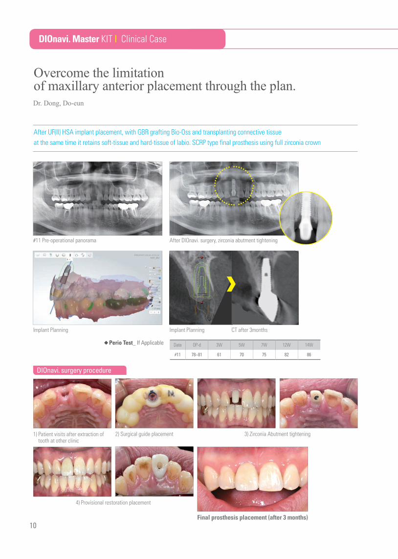
#11 Pre-operational panorama
Implant Planning CT after 3months
After DIOnavi. surgery, zirconia abutment tightening
Final prosthesis placement (after 3 months)
After UF(II) HSA implant placement, with GBR grafting Bio-Oss and transplanting connective tissue at the same time it retains soft-tissue and hard-tissue of labio. SCRP type final prosthesis using full zirconia crown
10
Date OP-d 3W 5W 7W 12W 14W
#11 78~81 61 70 75 82 86
◆Perio Test_ If Applicable
Overcome the limitationof maxillary anterior placement through the plan.
DIOnavi. Master KIT | Clinical Case
1) Patient visits after extraction of tooth at other clinic
4) Provisional restoration placement
2) Surgical guide placement 3) Zirconia Abutment tightening
Implant Planning
Dr. Dong, Do-eun
DIOnavi. surgery procedure
Navigation Implant
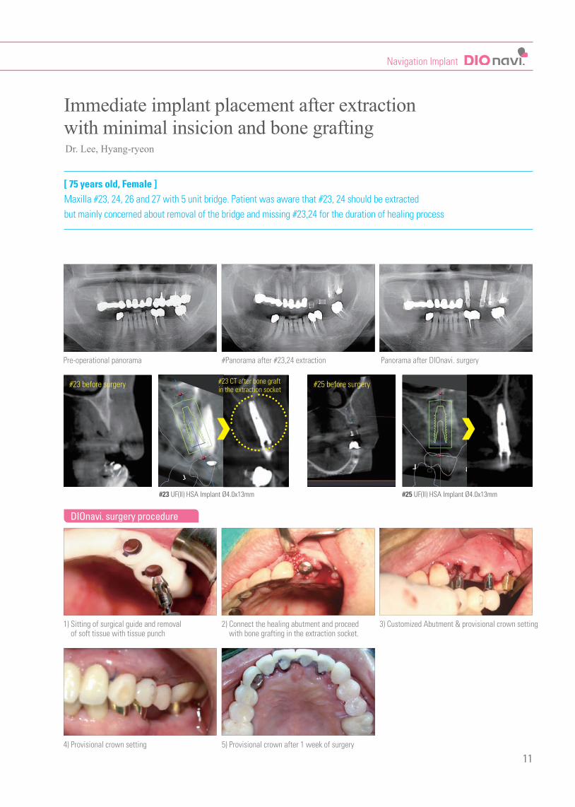
[ 75 years old, Female ] Maxilla #23, 24, 26 and 27 with 5 unit bridge. Patient was aware that #23, 24 should be extractedbut mainly concerned about removal of the bridge and missing #23,24 for the duration of healing process
11
Overcome the limitationof maxillary anterior placement through the plan.
Immediate implant placement after extractionwith minimal insicion and bone grafting
DIOnavi. surgery procedure
Pre-operational panorama
1) Sitting of surgical guide and removal of soft tissue with tissue punch
4) Provisional crown setting
#Panorama after #23,24 extraction
2) Connect the healing abutment and proceed with bone grafting in the extraction socket.
5) Provisional crown after 1 week of surgery
Panorama after DIOnavi. surgery
3) Customized Abutment & provisional crown setting
#23 before surgery #25 before surgery#23 CT after bone graftin the extraction socket
#23 UF(II) HSA Implant Ø4.0x13mm #25 UF(II) HSA Implant Ø4.0x13mm
Dr. Lee, Hyang-ryeon

DIOnavi. Navigation Implant
DIOnavi. Narrow Surgical Kit Order Code_ UF 14
12
Outstanding cutting forces and durability.Available for UF(II) Narrow system
Ratchet Wrench
DIO IMPLANT
Tissue Punch
5mmGuide Drill
Initial Drill
Drill Tube
Final Drill Ø2.5 Final Drill Ø2.7 Final Drill Ø3.0
Profile DrillImplant
Conncentor Connector Extension
CE 65
08A
CE 65
08M
AbutmentProfile Drill
Bone Flattening Drill
Digital Implant No.1 DIO
Tissue Punch1 3 Guide Drill2 Bone Flattening Drill
13
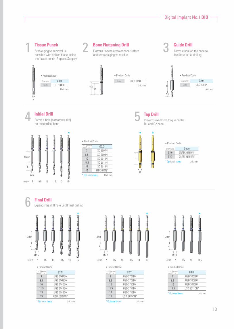
Stable gingiva removal is possible with a fixed blade inside the tissue punch (Flapless Surgery)
Forms a hole on the bone to facilitate initial drilling
Flattens uneven alveolar bone surfaceand removes gingiva residue
4 Initial DrillForms a hole (osteotomy site) on the cortical bone
5 Tap DrillPrevents excessive torque on the D1 and D2 bone
Unit: mm
Ø2.0UGD 2005N
Diameter
Code
■ Product Code
5.5
12Unit: mm
UBFD 3430Code
■ Product Code
1213.5
Ø3.0GTP 3430
Diameter
Code
■ Product Code
Unit: mm
D
Ø2.0ISD 2007N
8.5
Diameter
Unit: mm
Length
7
1011.51315
ISD 2008NISD 2010NISD 2011NISD 2013NISD 2015N*
■ Product Code
*
Ø2.0
Length 7 8.5 10 11.5 13 15
12mm
L
D
12
Unit: mm
CodeGNTD 3018DN*GNTD 3318DN*
Diameter
■ Product Code
Ø3.0Ø3.3
* *
* Optional items
* Optional items * Optional items
* Optional items
* Optional items
6 Final Drill
Ø2.5USD 2507DNUSD 2508DNUSD 2510DNUSD 2511DNUSD 2513DN
USD 2515DN*
8.5
Diameter
Unit: mm
Length
7
1011.51315
■ Product Code
Ø3.0USD 3007DNUSD 3008DNUSD 3010DN
USD 3011DN*
8.5
Diameter
Unit: mm
Length
7
1011.5
■ Product Code
Ø3.0
Length 7 8.5 10 11.5
L
12mm
Ø2.5
Length 7 8.5 10 11.5 13 15
L
12mm
*
Ø2.7USD 2707DNUSD 2708DNUSD 2710DNUSD 2711DNUSD 2713DN
USD 2715DN*
8.5
Diameter
Unit: mm
Length
7
1011.51315
■ Product Code
Ø2.7
Length 7 8.5 10 11.5 13 15
L
12mm
* *
Expands the drill hole untill final drilling

DIOnavi. Navigation Implant
10 Implant Connector98 Abutment Profile DrillProfile Drill
Ratchet Wrench
DRW 070Code
■ Product Code
Drill Tube
DIO IMPLANT
Surgical Protocol
14
Forms an emergency profile afterremoving the cortical bone whenplacing the abutment
Prevents excessive torque by expanding the cortical bone on the D1 and D2 bone
To places an implant in accordancewith the pre-planned fixture depthand inner hex direction
To place the fixture with the use ofan implant connector
To fix the initial drill without shaking motion
Ø3.0 Ø3.3
12mm
Unit: mm
Code
GNPD 3305DNGNPD 3005DN
Diameter
■ Product Code
Ø3.0Ø3.3
1.7
12mm
Unit: mm
Code
GNIC 3618GNIC 3615
Length
■ Product Code
151812mm
Unit: mm
UAPD 3428Code
■ Product Code
UDTE 10Code
■ Product Code1
Ø2.0
12mm
TissuePunch
BoneFlattening
Drill
GuideDrill
(Ø2.0)
InitialDrill
(Ø2.0)Profile
DrillØ2.5 Ø2.7
Final Drill
Ø3.3
Ø3.0
TissuePunch
BoneDensity
BoneFlattening Drill Guide Drill Initial Drill
(Ø2.0) Profile Drill AbutmentProfile DrillØ2.5 Ø2.7 Ø3.0
Soft
Medium
Hard
Soft
Medium
Hard
Final Drill
▼ ▼ ▼ ▼ ▼ ▼ ▼
AbutmentProfile Drill
▼

15
DIOnavi. Narrow Surgical KIT | Clinical Case
Minimally invasive implant placement with DIOnavi.
[ Female, 49 years old ] Maxillary anterior bridge / Insufficient remaining bone / Scared at Implant surgeryAfter DIOnavi. surgery, planning temporary prosthetic considering aesthetic factor on the day of surgery.
#12 Extraction and Implant placement, fitting temporary prosthetics / Bone width 4.5mm → UF(II) Narrow Ø3.3 Fixture#21 Implant placement and fitting temporary prosthetic / Bone width 4.5mm → UF(II) Narrow Ø3.3 Fixture
1) Removal of bridge and extraction #12 tooth
5) UF(II) 3313S fixture (insertion) 6) Customized abutment (tightening)
4) Use bone flattening drill after fitting surgical guide for the narrow alveolar bone
2,3) Surgical guide, customized abutment and provisional crown are designed based on CT scan data & Trios scan data
pre-operational panorama Panorama after DIOnavi. Surgery
Completed prosthetics on the day of surgery
#12, Bone width 4.5mmUF(II) HSA Implant Ø3.3×13mm
#21, Bone width 4.5mmUF(II) HSA Implant Ø3.3×13mm
Implant planning Merging CT Scan Data & Trios Scan Data
DIOnavi. Surgery procedure
Dr. Kang, Jaeseok
DIOnavi. Navigation Implant
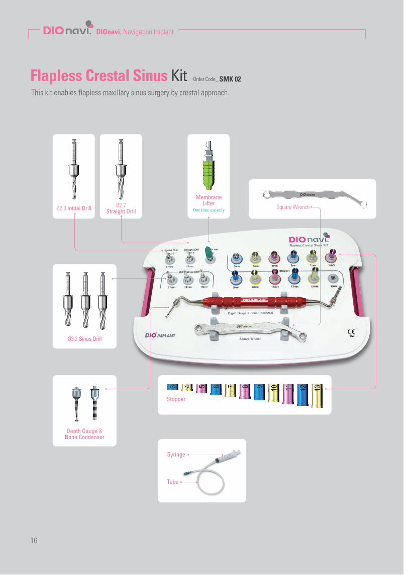
Flapless Crestal Sinus Kit Order Code_ SMK 02
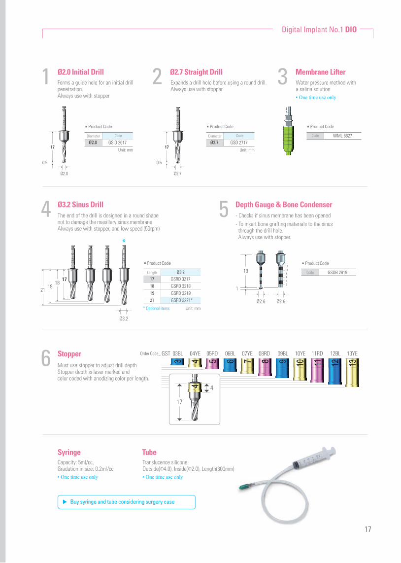
Ø2.0 Initial Drill
MembraneLifterØ2.7
Straight Drill
Ø3.2 Sinus Drill
Stopper
Square Wrench
Depth Gauge &Bone Condenser
Syringe
Tube
Ø2.0
× 1
7
Ø3.2
× 1
7
Ø3.2
× 1
8
Ø3.2
× 1
9
Ø2.7
× 1
7
16
This kit enables flapless maxillary sinus surgery by crestal approach.
One time use only
Digital Implant No.1 DIO
17
0.5
Ø2.0
Order Code_ GST 03BL 04YE 07YE 10YE 13YE05RD 08RD 11RD06BL 09BL 12BL
17
4
Ø2.0 Initial Drill
Ø3.2 Sinus Drill
Stopper
Depth Gauge & Bone Condenser
1
4
6
5
Forms a guide hole for an initial drillpenetration. Always use with stopper
The end of the drill is designed in a round shapenot to damage the maxillary sinus membrane.Always use with stopper, and low speed (50rpm)
Must use stopper to adjust drill depth.Stopper depth is laser marked and color coded with anodizing color per length.
Capacity: 5ml/cc,Gradation in size: 0.2ml/cc▪ One time use only
Translucence silicone.Outside(Φ4.0), Inside(Φ2.0), Length(300mm)▪ One time use only
▶ Buy syringe and tube considering surgery case
- Checks if sinus membrane has been opened- To insert bone grafting materials to the sinus through the drill hole. Always use with stopper.
Expands a drill hole before using a round drill. Always use with stopper
Water pressure method with a saline solution▪ One time use only
Syringe Tube
Ø2.0 GSID 2017Diameter Code
■ Product Code
Unit: mm
■ Product Code
Ø2.7 GSD 2717Diameter Code
Unit: mm
2 3Ø2.7 Straight Drill Membrane Lifter
■ Product Code
WML 6627Code
1719
2118
Ø3.2
17
0.5
Ø2.7
■ Product Code
Ø3.2GSRD 3217GSRD 3218GSRD 3219GSRD 3221*
Length
17181921
Ø2.0
× 1
7
Ø2.7
× 1
7
Ø3.2
× 1
7
Ø3.2
× 1
8
Ø3.2
× 1
9
Ø3.2
× 2
1
Unit: mm
■ Product Code
GSDB 2619Code19
1
Ø2.6 Ø2.6
12108642
*
17
* Optional items
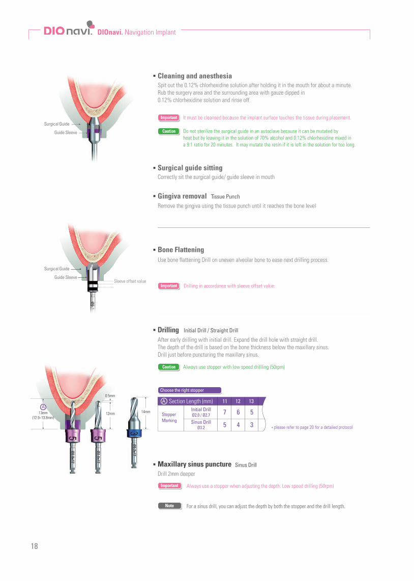
For a sinus drill, you can adjust the depth by both the stopper and the drill length.
Drilling Initial Drill / Straight Drill
After early drilling with initial drill. Expand the drill hole with straight drill.The depth of the drill is based on the bone thickness below the maxillary sinus.Drill just before puncturing the maxillary sinus.
Cleaning and anesthesia
Surgical guide sitting
Gingiva removal
Spit out the 0.12% chlorhexidine solution after holding it in the mouth for about a minute. Rub the surgery area and the surrounding area with gauze dipped in 0.12% chlorhexidine solution and rinse off.
Do not sterilize the surgical guide in an autoclave because it can be mutated by heat but by leaving it in the solution of 70% alcohol and 0.12% chlorhexidine mixed in a 9:1 ratio for 20 minutes. It may mutate the resin if it is left in the solution for too long.
It must be cleansed because the implant surface touches the tissue during placement.Important
Important
Caution
Caution
Correctly sit the surgical guide/ guide sleeve in mouth
Tissue Punch
Remove the gingiva using the tissue punch until it reaches the bone level
Use bone flattening Drill on uneven alveolar bone to ease next drilling process.
Bone Flattening
Maxillary sinus puncture Sinus Drill
Drill 2mm deeper
Always use a stopper when adjusting the depth. Low speed drilling (50rpm)
Drilling in accordance with sleeve offset value.
Important
Note
Surgical Guide
Guide Sleeve
Always use stopper with low speed drillling (50rpm)
StopperMarking
7 6 5
5 4 3
A Section Length (mm)Initial Drill
Sinus DrillØ2.0 / Ø2.7
Ø3.2
11 12 13
Choose the right stopper
* please refer to page 20 for a detailed protocol
13mm(12.9~13.8mm)
12mm 14mm
0.5mm
A
DIOnavi. Navigation Implant
18
Surgical Guide
Sleeve offset valueGuide Sleeve

Sinus membrane lift
Inject bone graft material
Remove the surgical guide and inject the saline solution into the drill hole using the membrane lifter.
By using only a bone condenser without the use of a surgical guide, inject the bone graft materials into the drill hole up into the sinus.
After lifting the sinus membrane, drill 2mm deeper with a sinus drill and expand the entrance of the sinus bone.
Place the implant using a surgical guideThe implant that entered the sinus, disperses the bone graft materials. If the amount of remaining bone is more than 4mm, initial fixation can be achieved,and temporary prosthetic can be placed after immediate placement
Inject 0.4cc after you feel the pressure. (excluding the initial amount of 0.2~0.5cc)
If the remaining bone is very thin – less than 3mm – and initial fixation cannot be achieved, only perform sinus bone graft and do not proceed immediate implant placement.
Always use a stopper to adjust the depth
Caution
Caution
Caution
Membrane Lifter
Bone condenser
Final Drill
0.1 0.2 0.3 0.4 0.5 0.6 0.7 0.8 0.9 1.0
0.3 0.6 0.9 1.2 1.5 1.8 2.1 2.4 2.7 3.0
1 2 3 4 5 6 7 8 9 10
Final Drilling
Implant placement
Digital Implant No.1 DIO
19
3.2x18
15mm
Note
Note
Note
※Case where sinus bone(A) is opened well
You can feel the pressure when injecting the saline solution and after the membrane is lifted, the pressure drops and saline is injected in the space.
※Case where sinus bone(A) s not opened well
After you feel the pressure, the nozzle is pushed out and no more pressure can be forced. ⇀Make a second attempt after drilling 1mm deeper with a sinus drill & Stopper.
Perform saline aspiration with a nozzle still in the hole.If negative pressure can be felt after the injected saline and blood mix together to form an aspiration, the membrane is safely lifted.
Spongy type bone graft material recommended for DIOnavi.In the case of immediate placement after bone graft, implant helps to keep the space inside the sinus with the spongy type bone graft material and promotes bone formation.
During this process, bone materials are diffused.
Sinus bone expansion
After lifting the sinus membrane, drill 1mm deeper with a sinus drill to expand the entrance to the sinus.
Always use a stopper to adjust the depthCaution
Sinus Drill (2nd)
Decide on the volume of bone graft material
Sinus membrane lifted height
Bonegraft GBR
(CC)
For immediate implant placement
For delayed implant placement
Lifted height

Sinus
BoneGingiva
Surgical guide+ Guide sleeve
11mm11~11.8mm
Sinus
Bone
Gingiva
Sinus
Bone
Gingiva
Surgical guide+ Guide sleeve
Tissue Punch
Tissue Punch
Tissue Punch
BoneFlattening Drill
You should be aware of offset value
when drilling.
You should be aware of offset value
when drilling.
You should be aware of offset value
when drilling.
additional drilling when it is not opened(Stopper 3mm)
additional drilling when it is not opened(Length 18mm / Stopper 3mm)
additional drilling when it is not opened(Length 19mm / Stopper 3mm)
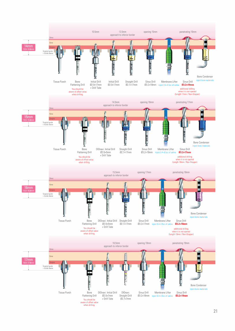
inject 0.4~0.5cc of saline.
inject 0.4~0.5cc of saline.
inject 0.4~0.5cc of saline.
inject bone materials
inject bone materials
inject bone materials
BoneFlattening Drill
BoneFlattening Drill
Initial DrillØ2.0×17mm + Drill Tube
Initial DrillØ2.0×17mm + Drill Tube
Initial DrillØ2.0×17mm + Drill Tube
Initial DrillØ2.0×17mm
Initial DrillØ2.0×17mm
Straight DrillØ2.7×17mm
Straight DrillØ2.7×17mm
Straight DrillØ2.7×17mm
Sinus DrillØ3.2×17mm
Sinus DrillØ3.2×17mm
Sinus DrillØ3.2×17mm
Bone Condenser
Bone Condenser
Bone Condenser
Sinus DrillØ3.2×17mm
Sinus DrillØ3.2×17mm
Sinus DrillØ3.2×18mm
Surgical guide+ Guide sleeve
12mm11.9~12.8mm
13mm12.9~13.8mm
Flapless Crestal Sinus KitProtocol
20
10.5mmapproach to inferior border
11.5mmapproach to inferior border
12.5mmapproach to inferior border
10.5mm
10.5mm
10.5mm
opening 12mm
opening 13mm
opening 14mm
penetrating 13mm
penetrating 14mm
penetrating 15mm
Membrane Lifter
Membrane Lifter
Membrane Lifter
Surgical protocol up to sinus bone expansion based on the length from the top of the sleeve to the sinus
Please check the planning file closely before surgery and follow the protocol guide during surgery.Caution
Sinus
Bone
Gingiva
Sinus
Bone
Gingiva
Surgical guide+ Guide sleeve
Surgical guide+ Guide sleeve
15mm14.9~15.8mm
14mm13.9~14.8mm
Sinus
Bone
Gingiva
Sinus
Bone
Gingiva
Surgical guide+ Guide sleeve
Tissue Punch
Tissue Punch
Tissue Punch
Tissue Punch
You should be aware of offset value
when drilling.
You should be aware of offset value
when drilling.
You should be aware of offset value
when drilling.
You should be aware of offset value
when drilling.
additional drillingwhen it is not opened
(Length 17mm / Non-Stopper)
additional drillingwhen it is not opened
(Length 18mm / Non-Stopper)
additional drillingwhen it is not opened
(Length 19mm / Non-Stopper)
inject 0.4~0.5cc of saline.
inject 0.4~0.5cc of saline.
inject 0.4~0.5cc of saline.
inject 0.4~0.5cc of saline.
inject bone materials
inject bone materials
inject bone materials
inject bone materials
BoneFlattening Drill
BoneFlattening Drill
BoneFlattening Drill
BoneFlattening Drill
Initial DrillØ2.0×17mm + Drill Tube
DIOnavi. Initial Drill Ø2.0×5mm + Drill Tube
DIOnavi. Initial Drill Ø2.0×5mm+ Drill Tube
DIOnavi. Initial Drill Ø2.0×7mm+ Drill Tube
Initial DrillØ2.0×17mm
Straight DrillØ2.7×17mm
Straight DrillØ2.7×17mm
Straight DrillØ2.7×17mm
DIOnavi.Straight DrillØ2.7×7mm
Sinus DrillØ3.2×18mm
Sinus DrillØ3.2×19mm
Sinus DrillØ3.2×17mm
Sinus DrillØ3.2×18mm
Bone Condenser
Bone Condenser
Bone Condenser
Bone Condenser
Sinus DrillØ3.2×19mm
Sinus DrillØ3.2×17mm
Sinus DrillØ3.2×18mm
Sinus DrillØ3.2×19mm
Surgical guide+ Guide sleeve
16mm15.9~16.8mm
17mm16.9~17.8mm
21
13.5mmapproach to inferior border
14.5mmapproach to inferior border
15.5mmapproach to inferior border
16.5mmapproach to inferior border
10.5mm opening 15mm
opening 16mm
opening 17mm
opening 18mm
penetrating 16mm
penetrating 17mm
penetrating 18mm
penetrating 19mm
Membrane Lifter
Membrane Lifter
Membrane Lifter
Membrane Lifter
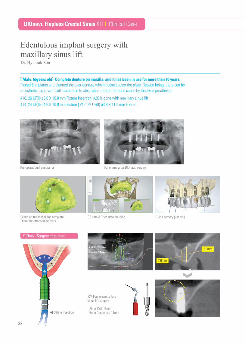
Pre-operational panorama Panorama after DIOnavi. Surgery
Edentulous implant surgery withmaxillary sinus lift
DIOnavi. Flapless Crestal Sinus KIT | Clinical Case
Guide surgery planningScanning the model and template.There are attached markers.
CT data & Trios data merging
8.9mm
7.0mm
#26 Flapless maxillary sinus lift surgery
- Sinus Drill 15mm- Bone Condenser 11mm◀ Saline Injection
22
[ Male, 66years old] Complete denture on maxilla, and it has been in use for more than 10 years.Placed 6 implants and planned the over-denture which doesn’t cover the plate. Reason being, there can be an esthetic issue with soft tissue due to absorption of anterior bone cause by the fixed prosthesis.
#16, 26 UF(II) ø5.0 X 10.0 mm Fixture Insertion, #26 is done with maxillary sinus lift#14, 24 UF(II) ø4.5 X 10.0 mm Fixture | #12, 22 UF(II) ø3.8 X 11.5 mm Fixture
Dr. Hyunrak Son
DIOnavi. Surgery procedure

Navigation Implant
※ Right after surgery
※ CT data : Surgery Plan vs After Surgery
#16UF(II) HSA ø5.0 X 10.0 mm
#22UF(II) HSA ø3.8 X 11.5 mm
#14UF(II) HSA ø4.5 X 10.0 mm
#24UF(II) HSA ø4.5 X 10.0 mm
#12UF(II) HSA ø3.8 X 11.5 mm
#26UF(II) HSA ø5.0 X 10.0 mm
23

DIOnavi. Navigation Implant
DIOnavi. Surgical Guide Fix / Anchor Kit Order Code_ SGF 02
24
Surgical Guid Fix Pin
Anchor Drill
Anchor Screw Surgical Guide Fix
Drill Tube
Anchor ScrewDriver
0 1.5 3
Ø2.0
× 1
5
Connect Guide Fix or fixture after placing implant and insert Fix Pin after initial drilling or use Anchor Screw to fix surgical guide in edentulous cases or free-end case

9mmOffset Offset
10.5mmOffset12mm
00
1.5 3
25
Digital Implant No.1 DIO
Surgical Guide Fix Pin
Surgical Guide Fix
Drill Tube Anchor Drill
1
2
3 4
Anchor Screw Driver5 Anchor Screw6
■ Product Code
■ Product Code ■ Product Code
SGFP 2008Code
UDT 20Code
■ Product Code
ASD 2513Code
AD 2015Code
■ Product Code
Ø6.3SGF 6309SGF 6310SGF 6312
Offset
910.512
Unit: mm
■ Product Code
Ø1.5ASC 1511ASC 1515
Lenth
1113
Unit: mm
1
Ø2.0
For mandibular
For maxillary
1115
Ø2.0
× 1
5
Use Guide Fix Pin after drilling ø2.0 to fix the surgical guide.
※ Using Bone Flattening Drill can reduce interference between bone and gingiva.
※ Regardless of offset, it is used after ø2.0x8.5mm drilling.
This is connected with implant fixture to fix the surgical guide.Color coded with offset value.
Drill tube minimizes deviation during the guide/initial drilling process.
Use only for anchor screw
Make a hole for an anchor
Anchor screw directly fix the surgical guide to gingiva
Subject of advice
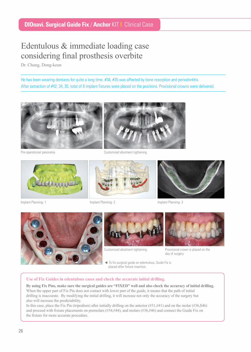
He has been wearing dentures for quite a long time. #34, #35 was affected by bone resorption and periodontitis.After extraction of #42, 34, 35, total of 8 implant fixtures were placed on the positions. Provisional crowns were delivered.
Edentulous & immediate loading case considering final prosthesis overbite
DIOnavi. Surgical Guide Fix / Anchor KIT | Clinical Case
Pre-operational panorama Customized abutment tightening
Implant Planning- 1 Implant Planning- 2
◀ To fix surgical guide on edentulous, Guide Fix is placed after fixture insertion.
Implant Planning- 3
Customized abutment tightening Provisional crown is placed on the day of surgery
26
Use of Fix Guides in edentulous cases and check the accurate initial drilling.By using Fix Pins, make sure the surgical guides are “FIXED” well and also check the accuracy of initial drilling. When the upper part of Fix Pin does not contact with lower part of the guide, it means that the path of initial drilling is inaccurate. By modifying the initial drilling, it will increase not only the accuracy of the surgery but also will increase the predictability.In this case, place the Fix Pin (tripodism) after initially drilling on the anterior (#31,#41) and on the molar (#36,$46) and proceed with fixture placements on premolars (#34,#44), and molars (#36,#46) and connect the Guide Fix on the fixture for more accurate procedure.
Dr. Chung, Dong-keun
Navigation Implant
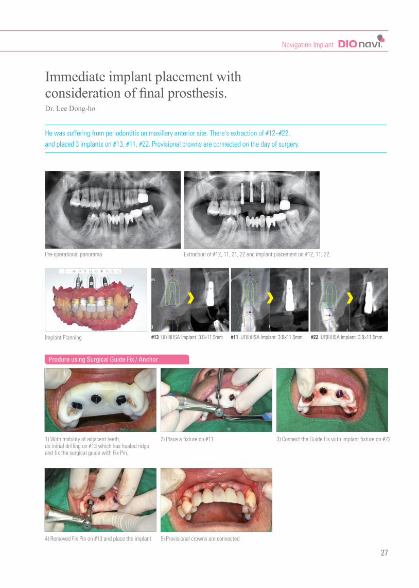
He was suffering from periodontitis on maxillary anterior site. There's extraction of #12~#22, and placed 3 implants on #13, #11, #22. Provisional crowns are connected on the day of surgery.
Immediate implant placement with consideration of final prosthesis.
Pre-operational panorama
1) With mobility of adjacent teeth, do initial drilling on #13 which has healed ridgeand fix the surgical guide with Fix Pin.
4) Removed Fix Pin on #13 and place the implant
2) Place a fixture on #11
5) Provisional crowns are connected
3) Connect the Guide Fix with implant fixture on #22
Implant Planning
Extraction of #12, 11, 21, 22 and implant placement on #12, 11, 22.
27
#13 UF(II)HSA Implant 3.8×11.5mm #11 UF(II)HSA Implant 3.8×11.5mm #22 UF(II)HSA Implant 3.8×11.5mm
Produre using Surgical Guide Fix / Anchor
Dr. Lee Dong-ho
Sterilization
Cleanse / Dry
01 Because all surgical tools are provided in a non-sterile condition, they must be cleansed and sterilized before using.
Caution
Wrong cleansing and sterilizing process causes corrosion and damage to the tools and if used directly, it may be the cause of 2nd infection.
02 The recommended number of use of a drill is 20~30 times based on the bone status, and it must be replaced if the blade has been damaged or transformed.
Caution If damaged drill is used, Heat Necrosis may occur
03 When managing the surgical tool, one must wear a mask and a glove to prevent infection.
01 Must only use antiseptic solution that is FDA and CE approved, and you must follow the manufacturer’s directions
02 When cleansing metal instruments, corrosion free antiseptic solution and cleansing product use is recommended.
03 For safety, one must always wear personal protection gear such as gloves, glasses, and masks.
04 The user has an obligation to be responsible for the sterilization and management of the instrument.
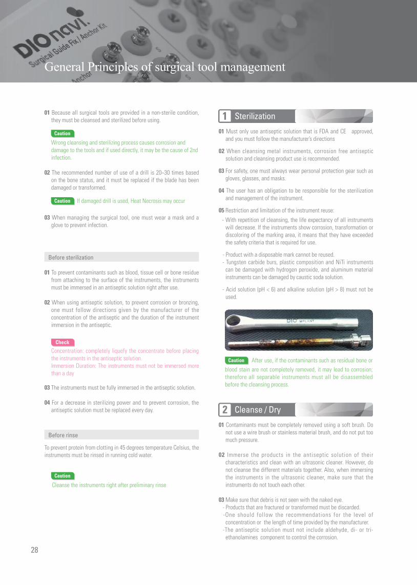
05 Restriction and limitation of the instrument reuse:
- With repetition of cleansing, the life expectancy of all instruments will decrease. If the instruments show corrosion, transformation or discoloring of the marking area, it means that they have exceeded the safety criteria that is required for use.
- Product with a disposable mark cannot be reused. - Tungsten carbide burs, plastic composition and NiTi instruments
can be damaged with hydrogen peroxide, and aluminum material instruments can be damaged by caustic soda solution.
- Acid solution (pH < 6) and alkaline solution (pH > 8) must not be used.
01 Contaminants must be completely removed using a soft brush. Do not use a wire brush or stainless material brush, and do not put too much pressure.
02 Immerse the products in the antiseptic solution of their characteristics and clean with an ultrasonic cleaner. However, do not cleanse the different materials together. Also, when immersing the instruments in the ultrasonic cleaner, make sure that the instruments do not touch each other.
03 Make sure that debris is not seen with the naked eye. - Products that are fractured or transformed must be discarded. -One should follow the recommendations for the level of
concentration or the length of time provided by the manufacturer. -The antiseptic solution must not include aldehyde, di- or tri-
ethanolamines component to control the corrosion.
Caution After use, if the contaminants such as residual bone or blood stain are not completely removed, it may lead to corrosion; therefore all separable instruments must all be disassembled before the cleansing process.
1
2
Before sterilization
01 To prevent contaminants such as blood, tissue cell or bone residue from attaching to the surface of the instruments, the instruments must be immersed in an antiseptic solution right after use.
02 When using antiseptic solution, to prevent corrosion or bronzing, one must follow directions given by the manufacturer of the concentration of the antiseptic and the duration of the instrument immersion in the antiseptic.
Check
Concentration: completely liquefy the concentrate before placing the instruments in the antiseptic solution. Immersion Duration: The instruments must not be immersed more than a day
03 The instruments must be fully immersed in the antiseptic solution.
04 For a decrease in sterilizing power and to prevent corrosion, the antiseptic solution must be replaced every day.
Before rinse
To prevent protein from clotting in 45 degrees temperature Celsius, the instruments must be rinsed in running cold water.
Caution
Cleanse the instruments right after preliminary rinse
28
General Principles of surgical tool management

Packaging
Pasteurization
01 Check on the dry status of the instruments and pack in the sterilized wrapping paper.
02 On the sterilized wrapping paper, attach a direction tape to check the date of sterilization. Check on the expiration date on the sterilized wrapping paper. Wrapping paper must be able to withstand up to 141 degrees that coincides with the EN ISO 11607.
01 Pasteurization process must follow the sterilizer equipment manufacturer. ◉ 4~ 18 minutes in 134’C for autoclave sterilization
02 Instruments and plastic components must be sterilized based on their packaging label.
- Sterilizer must coincide with the requirements of EN 13060 and EN285.
- Sterilization process must regard the ISO 11607. - One must follow the sterilization process and maintenance process
of the sterilizer provided by the manufacturer. - Efficiency management (Proper packaging, no humidity, change in
color of the sterilization dashboard)
01 Contaminants must be completely removed using a soft brush. Do not use a wire brush or stainless material brush, and do not put too much pressure.
02 Immerse the products in the antiseptic solution of their characteristics and clean with an ultrasonic cleaner. However, do not cleanse the different materials together. Also, when immersing the instruments in the ultrasonic cleaner, make sure that the instruments do not touch each other.
03 Make sure that debris is not seen with the naked eye. - Products that are fractured or transformed must be discarded. -One should follow the recommendations for the level of
concentration or the length of time provided by the manufacturer. -The antiseptic solution must not include aldehyde, di- or tri-
ethanolamines component to control the corrosion.
04 After cleaning, the products must be rinsed with distilled water or deionized water for at least a minute. If the antiseptic solution contains corrosion inhibitor, rinsing before placing in the sterilizer is recommended.
05 To prevent corrosion or water stain on the instruments, completely dry with a dryer or filtered compressed air
06 To prevent corrosion, decrease in sterilizing power, and contamination, antiseptic must be supplemented every day.
3
4
Check
Check on the instruments for faults (fracture, transformation, or corrosion). If necessary, assemble the instruments. Contaminated instruments must be cleansed or disinfected. Transformations that may affect the safety, performance or tolerance of the instruments; in other words; bent, damaged (fractured, corroded), or faulty products (discoloration of marking area, Loss) must be destroyed.
29
Surgery
Cleanse
Dry
Pack
Storage
Pasteurization
Surgical ToolMainteance
Process
Sterilization
Caution
If the instruments are not properly rinsed, residue is left behind, or is not properly dried, the sterilization process might discolor or corrode the instruments, and therefore the whole process must be gone through again.
Caution
Corrosion may start if debris such as blood stain or bone residue is not completely removed. They must be cleansed right after use and the debris must be completely removed when cleaning.

Digital Navigation Implant
Date of publication | June 2015Editing | DIO Implant Marketing teamPublisher | DIO Implant Headquarters


DIOnavi01E Ver.02_201511
DIO Implant 66, Centum seo-ro, Haeundae-gu, Busan 612-020, Korea Tel +82 51 745 7777 Fax +82 51 745 7778 www.dioimplant.com