Embed Size (px)
Citation preview
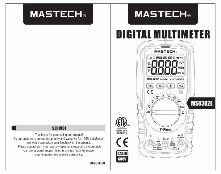
DIGITAL MULTIMETER
CAT.III
600V
SERVICE
00-05-3768
Thank you for purchasing our product! As our customers are our top priority and we strive for 100% satisfaction,
we would appreciate your feedback on the product. Please contact us if you have any questions regarding the product.
Our professional support team is always ready to answer your enquiries and provide assistance.
4
MS8302E
MS8302E
1 2
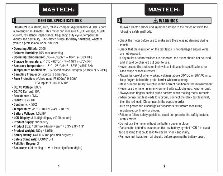
1. GENERAL SPECIFICATIONS
MS8302E is a stable, safe, reliable compact digital handheld 6000 count auto-ranging multimeter. This meter can measure AC/DC voltage, AC/DC current, resistance, capacitance, frequency, duty cycle, temperature, diodes and continuity. This meter is ideal for many situations, whether you're a professional or causal user.
• Safety Rating: CAT III 600V; pollution degree: II
• Operating Altitude: 2000m
• Relative Humidity: 75% max operating
• Operating Temperature: 0°C~40°C/32°F~104°F (<80% RH)
• Storage Temperature: -10°C~60°C/14°F~140°F (<70% RH)
• Accuracy Temperature: -18°C~28°C/64°F~82°F (<80% RH)
• Temperature Coefficient: 0.1x(specified accuracy)/°C (<18°C or >28°C)
• Sampling Frequency: approx. 3 times/sec.
• Fuse Protection: µA/mA input: FF 600mA H 600V
10A input: FF 10A H 600V
• DC/AC Voltage: 600V
• DC/AC Current: 10A
• Resistance: 40MΩ
• Diodes: 3.2V DC
• Continuity: <50Ω
• Temperature: -20°C~1000°C/-4°F~1832°F
• Battary Voltage: 1.5V/9V
• LCD Display: 3 ¾ digit display (4000 counts)
• Product Supply: 9V battery
• Product Size: 150mm×74mm×48mm / 6.3"×2.9"×1.9"
• Product Weight: 482g / 1.06lb
• Safety Standards: IEC61010-1
• Pollution Degree: 2
• Accuracy: ±(of reading + # of least significant digits)
2. WARNINGS
Check the meter before use to make sure there was no damage during
transit.
Check that the insulation on the test leads is not damaged and/or wires
are not exposed.
If any faults or abnormalities are observed, the meter should not be used
and should be checked out prior to use.
Never exceed the protection limit values indicated in specifications for
each range of measurement.
Always be careful when working voltages above 60V DC or 30V AC rms,
keep fingers behind the probe barrier while measuring.
Make sure the rotary switch is in the correct position before measurement.
Never use the meter in an environment with explosive gas, vapor or dust.
Always keep fingers behind probe barriers when making measurements.
When connecting test leads to a circuit, connect the black test lead first,
then the red lead. Disconnect in the opposite order.
Turn off power and discharge all capacitors first before measuring
resistance, continuity or diodes.
Failure to follow safety guidelines could compromise the safety features
of this meter.
Do not use the meter without the battery cover in place.
Replace the batteries as soon as the low battery symbol “ ” to avoid
false reading that could lead to electric shock and injury.
Remove test leads from all circuits before opening the battery cover.
•
•
•
•
•
•
•
•
•
•
•
•
•
•
To avoid electric shock and injury or damage to the meter, observe the
following safety methods:
4
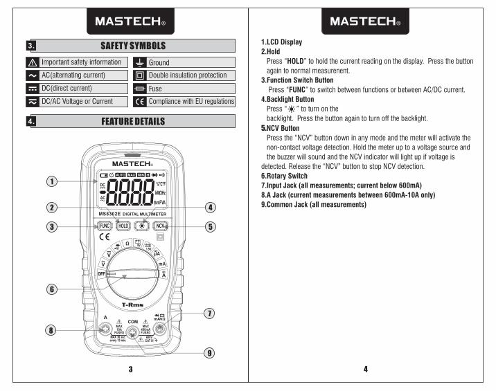
3. SAFETY SYMBOLS1.LCD Display
4.
2.Hold
Press “HOLD” to hold the current reading on the display. Press the button
again to normal measurenent.
3.Function Switch Button
Press “FUNC” to switch between functions or between AC/DC current.
Backlight Button
Press “ ” to turn on the
backlight. Press the button again to turn off the backlight.
5.
6.Rotary Switch
7.Input Jack (all measurements; current below 600mA)
8.A Jack (current measurements between 600mA-10A only)
9.Common Jack (all measurements)
NCV Button
Press the “NCV” button down in any mode and the meter will activate the
non-contact voltage detection. Hold the meter up to a voltage source and
the buzzer will sound and the NCV indicator will light up if voltage is
detected. Release the “NCV” button to stop NCV detection.
Important safety information
AC(alternating current)
DC(direct current)
DC/AC Voltage or Current
Double insulation protection
Fuse
Compliance with EU regulations
Ground
4. FEATURE DETAILS
3
5
4
3
2
6
8
7
9
1
4
MS8302E
4
4
2
1
6 7 9 8
4
5
3
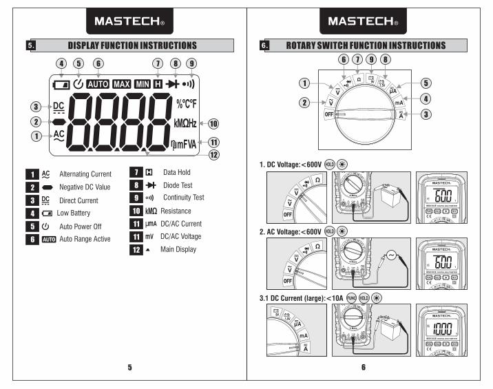
5. DISPLAY FUNCTION INSTRUCTIONS
3
2
5
6
Direct Current
Alternating Current
Negative DC Value
Auto Power Off
Auto Range Active
7
8
Data Hold
Diode Test
9 Continuity Test
6. ROTARY SWITCH FUNCTION INSTRUCTIONS
4 Low Battery
12 Main Display
10
11
11
Resistance
DC/AC Current
DC/AC Voltage2. AC Voltage:<600V
6
3.1 DC Current (large):<10A
5
1. DC Voltage:<600V
1
4 5 6 7 8 9
2
3
1
10
11
12
MS8302E
MS8302E
MS8302E
4
7 8
MS8302E
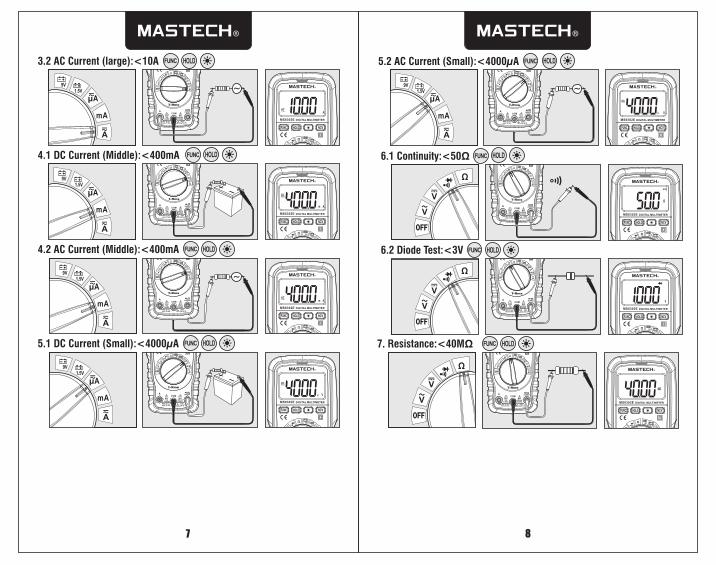
AC Current (large):<10A3.2
4.1 DC Current (Middle):<400mA
AC 4.2 Current (Middle):<400mA
AC 5.2 Current (Small):<4000µA
5.1 DC Current (Small):<4000µA
4
4
4
4
4
MS8302E
MS8302E
MS8302E
MS8302E
4
6.1 Continuity:<50Ω
6.2 Diode Test:<3V
4
4
MS8302E
MS8302E
MS8302E
7. Resistance:<40MΩ
6
MS8302E
9
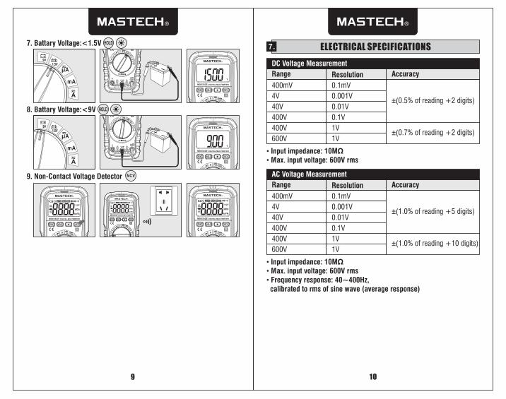
9. Non-Contact Voltage Detector NCV
7. ELECTRICAL SPECIFICATIONS
DC Voltage Measurement
Range Resolution Accuracy
400mV 0.1mV
±(0.5% of reading +2 digits)4V
40V
400V
0.001V
0.01V
0.1V
• Input impedance: 10MΩ• Max. input voltage: 600V rms
AC Voltage Measurement
Range Resolution Accuracy
400mV 0.1mV
±(1.0% of reading +5 digits)4V
40V
400V
0.001V
0.01V
0.1V
• Input impedance: 10MΩ• Max. input voltage: 600V rms• Frequency response: 40~400Hz, calibrated to rms of sine wave (average response)
10
400V 1V
400V 1V
MS8302E
6
MS8302E
7. Battary Voltage:<1.5V
4
4
8. Battary Voltage:<9V
MS8302E
MS8302E
600V 1V±(0.7% of reading +2 digits)
600V 1V±(1.0% of reading +10 digits)
11 12
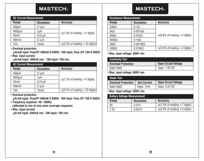
AC MeasurementCurrent
Range Resolution Accuracy
400 Aµ 0.1µA
±(1.2% of reading +5 digits)4000µA
40mA
400mA
1µA
0.01µA
0.1µA
• Overload protection: µA/mA input: Fuse(FF 400mA H 600V) 10A input: Fuse (FF 10A H 600V)• Frequency response: 40~400Hz, calibrated to rms of sine wave (average response)• Max. input current: µA/mA input: 400mA rms 10A input: 10A rms
10A 10mA ±(2.5% of reading +10 digits)
Resistance Measurement
Range Resolution Accuracy
400Ω 0.1Ω
±(0.8% of reading +5 digits)
4kΩ
40kΩ
400kΩ
0.001kΩ
0.01kΩ
0.1kΩ
• Max. input voltage: 600V rms
4MΩ 0.001MΩ
40MΩ 0.01MΩ
Continuity Test
Overload Protection Open Circuit Voltage
600V RMS Appx. 1.0V DC
• Max. input voltage: 600V rms
Diode Test
Overload Protection Open Circuit Voltage
600V RMS Appx. 3.2V DC
• Max. input voltage: 600V rms
Test Current
Appx. 1mA
±(2.0% of reading +5 digits)
DC Current Measurement
Range Resolution Accuracy
400µA 0.1µA
±(1.0% of reading +5 digits)4000µA
40mA
400mA
1µA
0.01µA
0.1µA
• Overload protection: µA/mA input: Fuse(FF 400mA H 600V) 10A input: Fuse (FF 10A H 600V)• Max. input current: µA/mA input: 400mA rms 10A input: 10A rms
10A 10mA ±(2.0% of reading +10 digits)
Battary Voltage Measurement
Range Resolution Accuracy
9V 0.01V ±(1.2% of reading +7 digits)
1.5V 0.001V ±(3.0% of reading +5 digits)
15 16
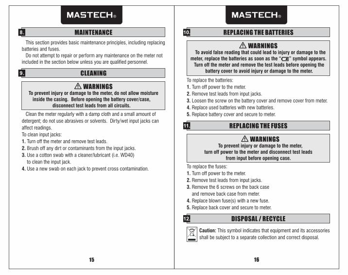
9. CLEANING
WARNINGS To prevent injury or damage to the meter, do not allow moisture
inside the casing. Before opening the battery cover/case, disconnect test leads from all circuits.
Clean the meter regularly with a damp cloth and a small amount of
detergent; do not use abrasives or solvents. Dirty/wet input jacks can
affect readings.
To clean input jacks:
1. Turn off the meter and remove test leads.
2. Brush off any dirt or contaminants from the input jacks.
3. Use a cotton swab with a cleaner/lubricant (i.e. WD40)
to clean the input jack.
4. Use a new swab on each jack to prevent cross contamination.
11. REPLACING THE FUSES
WARNINGS To prevent injury or damage to the meter,
turn off power to the meter and disconnect test leads from input before opening case.
To replace the fuses:
1. Turn off power to the meter.
2. Remove test leads from input jacks.
Remove the 6 screws on the back case
and remove back case from meter.
4. Replace blown fuse(s) with a new fuse.
5. Replace back cover and secure to meter.
3.
10. REPLACING THE BATTERIES
To replace the batteries:
1. Turn off power to the meter.
2. Remove test leads from input jacks.
3. Loosen the screw on the battery cover and remove cover from meter.
4. Replace used batteries with new batteries.
5. Replace battery cover and secure to meter.
WARNINGS To avoid false reading that could lead to injury or damage to the meter, replace the batteries as soon as the “ ” symbol appears. Turn off the meter and remove the test leads before opening the
battery cover to avoid injury or damage to the meter.
8. MAINTENANCE
This section provides basic maintenance principles, including replacing batteries and fuses. Do not attempt to repair or perform any maintenance on the meter not included in the section below unless you are qualified personnel.
12. DISPOSAL / RECYCLE
Caution: This symbol indicates that equipment and its accessories
shall be subject to a separate collection and correct disposal.