Embed Size (px)
Citation preview
DIGITAL MPA II™ ART DIGITAL MPA II™ Microphone Preamplifier
USER’S GUIDE

II
IMPORTANT SAFETY INSTRUCTIONS – READ FIRST This symbol, wherever it appears, This symbol, wherever it appears, alerts alerts you to the presence of uninsulated you to important operating and maintenance dangerous voltage inside the enclosure. Voltage instructions in the accompanying literature. that may be sufficient to constitute a risk of shock. Please read manual. Read instructions: Retain these safety and operating instructions for future reference. Heed all warnings printed here and on the equipment. Follow the operating instructions printed in this user guide. Do not open: Aside from two vacuum tubes, there are no user serviceable parts inside. Refer any service work to qualified technical personnel only. Power sources: Only connect the unit to mains power of the type marked on the rear panel. The power source must provide a good ground connection. Power cord: Use the power cord with the mains plug appropriate for your local mains supply as provided with the equipment. If the provided plug does not fit into your outlet consult your service agent. Route the power cord so that it is not likely to be walked on, stretched or pinched by items placed upon or against. Grounding: Do not defeat the grounding and polarization means of the power cord plug. Do not remove or tamper with the ground connection on the power cord. Ventilation: Do not position the unit where the air required for ventilation is impeded. If the unit is to be operated in a rack, case or other furniture, ensure that it is constructed to allow adequate ventilation. Moisture: To reduce the risk of fire or electrical shock do not expose the unit to rain, moisture or use in damp or wet conditions. Do not place a container of liquid on it, which may spill into any openings. Heat: Do not locate the unit in a place close to excessive heat or direct sunlight, as this could be a fire hazard. Locate the unit away from any equipment, which produces heat such as: power supplies, power amplifiers and heaters. Environment: Protect from excessive dirt, dust, heat, and vibration when operating and storing. Avoid tobacco ash, drink spillage and smoke, especially that associated with smoke machines. Handling: To prevent damage to the controls and cosmetics avoid rough handling and excessive vibration. Protect the controls from damage during transit. Use adequate padding if you need to ship the unit. To avoid injury to yourself or damage to the equipment take care when lifting, moving or carrying the unit. Servicing: Switch off the equipment and unplug the power cord immediately if it is exposed to moisture, spilled liquid, objects fallen into opening, or the power cord or plug becomes damaged during a lightning storm or if smoke odor or noise is noted. Refer servicing to qualified technical personnel only. Installation: Install the unit in accordance with the instructions printed in the user guide.

III
IMPORTANT SAFETY INSTRUCTIONS – READ FIRST ......................................................... II
DIGITAL MPA II OVERVIEW – FEATURES AND GENERAL INFORMATION: ...................... 1
FRONT PANEL CONNECTIONS AND CONTROLS ................................................................ 3 Input Gain control ..................................................................................................................................... 3 Input Impedance control ........................................................................................................................... 4 Low Cut Filter control................................................................................................................................ 4 Gain switch ............................................................................................................................................... 4 Phantom switch ........................................................................................................................................ 5 Phase switch............................................................................................................................................. 5 Plate Voltage switch ................................................................................................................................. 5 Mid/Side switch......................................................................................................................................... 6 Analog Output control ............................................................................................................................... 6 STEREO/Dual switch................................................................................................................................ 6 +4/-10 switch (rear panel) ......................................................................................................................... 7 Meter Trim ................................................................................................................................................ 7 Digital section front panel controls........................................................................................ 7 Digital Level control .................................................................................................................................. 7 Sample Rate control ................................................................................................................................. 8 Dither settings........................................................................................................................................... 9 Optical switch............................................................................................................................................ 9 Front Panel connections ....................................................................................................... 10 Instrument Inputs .................................................................................................................................... 10 Rear Panel connections ........................................................................................................ 11 Balanced Inputs ...................................................................................................................................... 11 Balanced Outputs ................................................................................................................................... 11 Insert jacks.............................................................................................................................................. 12 Wordclock jacks...................................................................................................................................... 12 ADAT Input ............................................................................................................................................. 12 Optical output.......................................................................................................................................... 12 S/PDIF output ......................................................................................................................................... 13 AES/EBU output ..................................................................................................................................... 13 DIGITAL MPA II OPERATING INSTRUCTIONS..................................................................... 14 Obtaining the best noise performance with the DIGITAL MPA II............................................................ 14 Adjusting the Input Impedance ............................................................................................................... 14 Obtaining the perfect digital level setting ................................................................................................ 15 Setting the Tube Plate Voltage ............................................................................................................... 16 Using the Mid/Side mode........................................................................................................................ 17 WARRANTY INFORMATION.................................................................................................. 18
SERVICE ................................................................................................................................. 19
DIGITAL MPA II SPECIFICATIONS........................................................................................ 20 Analog Section:....................................................................................................................................... 20 Digital Section:........................................................................................................................................ 20 List of Figures Figure 1 – Block Diagram .......................................................................................................... 2 Figure 2 – Front controls ............................................................................................................ 3 Figure 4 – Rear connections .................................................................................................... 11 Figure 4 – Mid/Side Mic alignment........................................................................................... 17
1
DIGITAL MPA II OVERVIEW – FEATURES AND GENERAL INFORMATION:
The ART DIGITAL MPA II microphone preamplifier features a new low noise, high performance
preamplification circuitry, designed for superior audio fidelity. Building upon the quality and success of
great sounding products like the Pro MPA and MPA GOLD, ART engineers set out to develop the
next generation of professional microphone preamplifier. The DIGITAL MPA II is the culmination of
years of research and development, and sets a new standard for quality and value. Professional
features and spectacular tone are what make the DIGITAL MPA II a world-class microphone pream-
plifier. Its impressive feature set includes:
• Variable input impedance for flexible microphone voicing (150 Ohms to 2400 Ohms). • Selectable plate voltage • Large VU meters • Front accessible meter trim • Selectable between output level and tube warmth • Improved discrete class A input microphone preamplifier • Lower noise at low gains • Lower THD • Wider frequency response • Front accessible Instrument Input Jack • Very high input impedance • Mid/Side micing support • +4dBm/-10dBV output level selection • Automatically switches to the instrument input when you plug in
The DIGITAL MPA II also features digital connectivity for use with various digital processors and digital recording devices. The Digital interface supports the following features and functions:
• 24-204KHz External sample rate • 44.1K, 48K, 88.2K, 96K, 176.4K, 192K Internal sample rates • 24/16 bit switchable dithering • Wide dynamic range A/D • Rotary Encoder for quick selection of sample rate • Separate analog and digital output level controls • Digital Level LED meters display both Average and Peak level. • ADAT optical I/O • Sync to incoming ADAT data rate • Switch selectable optical output (S/PDIF or ADAT) • AES/EBU and S/PDIF outputs • Two wordclock jacks allowing loop through
2
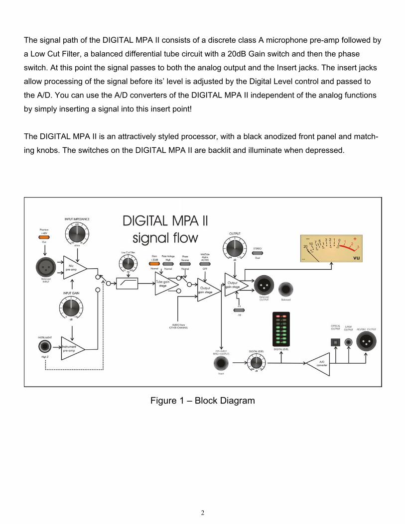
The signal path of the DIGITAL MPA II consists of a discrete class A microphone pre-amp followed by
a Low Cut Filter, a balanced differential tube circuit with a 20dB Gain switch and then the phase
switch. At this point the signal passes to both the analog output and the Insert jacks. The insert jacks
allow processing of the signal before its’ level is adjusted by the Digital Level control and passed to
the A/D. You can use the A/D converters of the DIGITAL MPA II independent of the analog functions
by simply inserting a signal into this insert point!
The DIGITAL MPA II is an attractively styled processor, with a black anodized front panel and match-
ing knobs. The switches on the DIGITAL MPA II are backlit and illuminate when depressed.
Figure 1 – Block Diagram
3
FRONT PANEL CONNECTIONS AND CONTROLS
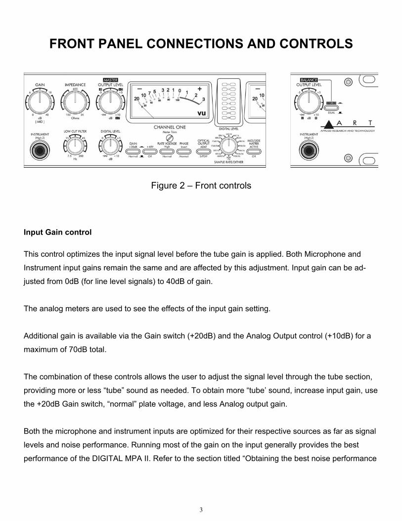
Figure 2 – Front controls
Input Gain control
This control optimizes the input signal level before the tube gain is applied. Both Microphone and
Instrument input gains remain the same and are affected by this adjustment. Input gain can be ad-
justed from 0dB (for line level signals) to 40dB of gain.
The analog meters are used to see the effects of the input gain setting.
Additional gain is available via the Gain switch (+20dB) and the Analog Output control (+10dB) for a
maximum of 70dB total.
The combination of these controls allows the user to adjust the signal level through the tube section,
providing more or less “tube” sound as needed. To obtain more “tube’ sound, increase input gain, use
the +20dB Gain switch, “normal” plate voltage, and less Analog output gain.
Both the microphone and instrument inputs are optimized for their respective sources as far as signal
levels and noise performance. Running most of the gain on the input generally provides the best
performance of the DIGITAL MPA II. Refer to the section titled “Obtaining the best noise performance
4
with the DIGITAL MPA II for more detailed instructions on setting the Input Gain control for the best
results.
Input Impedance control
This knob controls the Mic/line input amplifier impedance. This function allows variable voicing of any
microphone.
Refer to the application section titled “Adjusting the Input Impedance” for more information on making
the most of this function.
The ¼” instrument input is NOT affected by this control, and remains high (>1M Ohm) impedance.
Low Cut Filter control
The Low Cut Filter is a single tuned High Pass Filter that is frequency tunable. The input signal can
be filtered to remove “pops” or other extraneous low frequency information. This control moves the
rolloff frequency from 10 Hz (fully CCW) to 200 Hz (fully CW). Since it is single tuned, it preserves
some low frequency content so its use is less obtrusive. It is especially useful in close mic’d applica-
tions.
Gain switch
The Gain switch is used in conjunction with the input gain control to adjust signal levels through the
DIGITAL MPA II. When depressed, the tube circuit provides 20dB more gain in the signal path. This
also has the effect of driving the tube harder and making the tube the dominant source of gain and
overload character.
5
Phantom switch
Phantom power on the microphone input is turned on and off with this switch. Depressing the switch
will power condenser microphones and other 48volt phantom powered devices. Phantom power is
supplied to pins 2 and 3 of the input jack.
NOTE:
1) Dynamic microphones are NOT affected by Phantom power, although it should be turned off when
using dynamic microphones or line level inputs.
2) Although the 48volt phantom power ramps up and down slowly it may still create a pop. Mute the
output of the DIGITAL MPA II when engaging or disengaging phantom power to prevent damage to
equipment following the DIGITAL MPA II.
Phase switch
The Phase switch can invert the phase of the audio signal path in either channel. The Phase switch
is located after the tube circuit in the signal path, so you can hear slight differences between different
phase selections in the “normal” plate voltage mode near saturation. There are a number of reasons
why adjusting the phase is needed these include, wiring errors and inversions in some audio equip-
ment. Some microphones sound different depending on the phase chosen.
If two microphones are out of phase, they may cancel at various frequencies (depending on the
distance between them). If this happens, try changing the phase of one of the microphones and see if
there is an improvement.
Plate Voltage switch
This switch sets both the tube bias point and the plate voltage level the balanced differential tube
circuit runs at. The amount of headroom is adjusted by using the Gain switch and the input Gain
control. The DIGITAL MPA II takes about 10-30 seconds to smoothly transition from one mode to the
other. There is a slight increase in gain in the “High” plate voltage mode.

6
In the “Normal” (OUT) position, the tube distortion gradually rises until it smoothly clips. The tube is
run almost completely open-loop in this mode, providing a musical tube “crunch” when overdriven
with a natural recovery from clipping. The tube section can be more easily overdriven when the gain
switch is in. This mode brings out the harmonics in the input sources, particularly stringed instru-
ments.
The tube circuit runs extremely clean in the “High” (IN) position of the plate voltage switch. As signal
levels rise distortion remains very low until within 6dB of clipping, where the overload characteristics
smoothly limit the signal swing. There is increased bandwidth (>100KHz), and headroom in this mode
as well.
Mid/Side switch
The Mid/Side switch is used to decode Left/Right information when using two mics aligned for stereo
recording.
You can use either two figure-eight pattern mics or one omni-directional and one Figure-eight mic.
Analog Output control
The output signal level at the rear output jacks is adjusted by this control. It can provide from +10dB
of gain (fully clockwise) to completely muted. You can see the effects of this adjustment reflected in
the analog meters.
STEREO/Dual switch
The STEREO/Dual switch selects the operation of the output control knobs. Stereo mode gains and
operation are marked with reversed out text.
In Stereo mode, CH1 output adjusts the output gain of both channels and CH2 output control acts as
a power summed Balance control. There is a slight drop in output level in stereo mode when the
Balance knob is centered vs. at one extreme or another.
7
When the switch is in the “Dual” position the output controls act on only their respective channels.
+4/-10 switch (rear panel)
The +4/-10 switch is used to set the output level of the DIGITAL MPA II for the appropriate system
levels. This feature allows you to match 0 VU on the meters of the DIGITAL MPA II and your mixer or
other equipment.
When depressed, 0 VU on the output meter corresponds to +4dBu on the outputs. In –10 mode, the
output level measures –10dBV.
Meter Trim
The Meter Trim is used to adjust the Meter’s “0” point when. This may change if the unit is NOT
mounted with the front panel perpendicular to the floor.
Using a small flat-blade screwdriver you can mechanically fine-tune the meter indicator position if, for
example, it does not rest at the leftmost position when the unit is OFF.
Adjustments for feedback readings, when the unit is in use, are internal and are not user serviceable.
Digital section front panel controls
Digital Level control
The levels driving the A/D converter are adjusted with this control. The topology of the DIGITAL MPA
II lends itself to simultaneous use of the analog and digital outputs, as each has its’ own level control.
Common to both is the output signal of the tube circuit.
The Digital Level control is variable from +10dB to -∞ (fully muted).
Located before the Digital Level control is the insert jack, allowing processing to be added before
digital conversion.

8
As the Digital Level control is used refer to the Digital Level LED meter which indicates both peak and
average level present at the A/D converter input. This meter helps you get the perfect level adjust-
ment and avoid clipping the A/D. Refer to the section titled “Obtaining the perfect digital level setting”
for more detail on the operation and use of these features.
Sample Rate control
The Sample rate knob determines both the output sample rate of the DIGITAL MPA II as well as the
dither. You can select either AES/EBU (pro) format or S/PDIF (consumer) data format.
The internal sample rate can be set from 44.1KHz to 192KHz. Simply select the correct rate by
turning the knob to the rate you need and the DIGITAL MPA II will use its’ internal crystal controlled
oscillator to accurately generate the selected timing. Each sample rate has the option of either 24 bit
or 16 bit dither (i.e. 44.1K/24 or 44.1K/16).
Be careful in adjusting this control. Some equipment is not capable of the available sample rates and
may produce damaging side effects. Always turn down levels following the DIGITAL MPA II when
changing the sample rate.
External sync sources are Wordclock and ADAT INPUT.
Wordclock is a 5V logic level signal interfaced by a BNC connector on the rear of the unit. The Range
of wordclock accepted by the DIGITAL MPA II is 28KHZ to 212 kHz. It is recommended that you use
wordclock whenever possible, as this will minimize interface errors with other equipment.
NOTE: When using the ADAT optical output, the maximum sample rate is limited to about 50KHz. If
wordclock exceeds this the ADAT output (if selected) will fail.
The ADAT Input on the rear panel is used as a timing reference as well as a source of data to be
passed on to the ADAT output of the DIGITAL MPA II.
If the unit CANNOT sync to an external source (either out of range, not connected or a system fail-
ure), the optical Output select switch will blink. (You may see this switch flash once between changing
9
sample rates, indicating the fraction of a second it takes to settle to the new rate. This is normal).
NOTE: When using the ADAT Input as a sync source, the maximum sample rate is limited to about
50KHz.
Dither settings
The DIGITAL MPA II possesses a 24-bit A/D converter. When the output of the unit goes off to a
system that can handle only 16 bit data, the 8 least significant bits of data are ignored (truncated).
This leaves the sound with gritty “digital” sounding signals at very low levels. Setting the Sample Rate
selector to 16 bit adds a dither component that when truncated replaces this with a more musical
sound as the levels trail off into the noise floor.
Generally, keep the unit in 24-bit mode unless you are connected to a system that will truncate the
signal to 16 bits. The 24-bit mode has significantly greater dynamic range.
Optical switch
The optical output jack of the DIGITAL MPA II can have one of two formats. When this switch is
depressed AND lit blue, this jack will output 8 channels of ADAT. (ADAT cannot be output if the
sample rate exceeds 48KHZ. In this case the switch cap will NOT be illuminated, and the output
format will revert to 2-channel mode (TOSLINK). When ADAT output is active, The left channel of the
DIGITAL MPA II is output on CH1, the right channel of the DIGITAL MPA II is CH2, and the rest of the
channels consist of data received from the ADAT Input jack.
When the switch is in the OUT position OR the switch cap is not lit, the output consists of two chan-
nels of digital audio in the format selected by the Sample Rate Switch.
The Lighting of the optical switch cap serves a second function. If it is blinking, there is a timing
problem in the digital section. This usually happens when there is not a valid external timing input
selected.
10
Front Panel connections
Instrument Inputs
The ¼” jacks on the front panel serve as an instrument input. The input impedance is always >1M
Ohm and the gain can be adjusted by the Input gain control. The maximum input signal level is
+17dBu (5Vrms) @ minimum input gain.
When you plug into this jack it DISABLES the balanced input on the rear of the unit. This feature
allows you to keep the rear input patched in, and use the instrument input to switch to a different
source. The instrument input allows the DIGITAL MPA II to serve as a great DI device as well.
11
Rear Panel connections
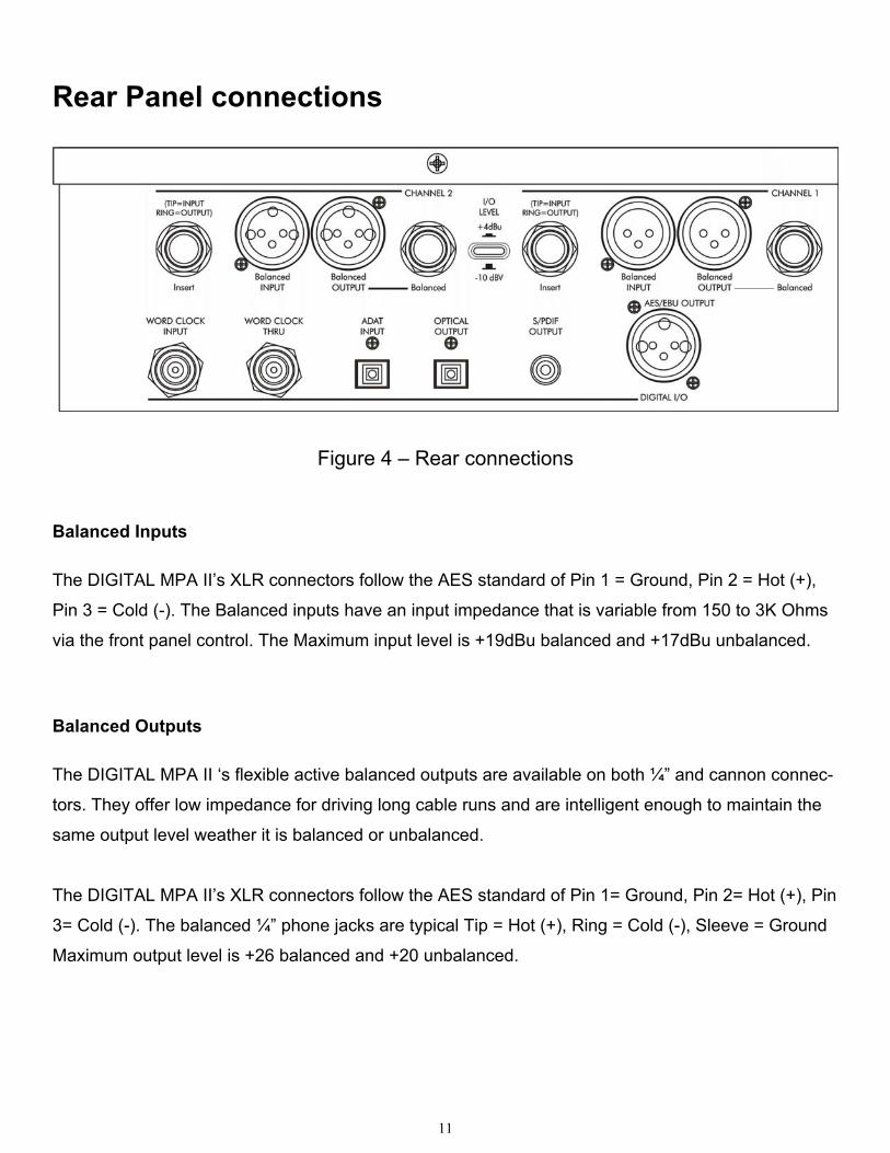
Figure 4 – Rear connections
Balanced Inputs
The DIGITAL MPA II’s XLR connectors follow the AES standard of Pin 1 = Ground, Pin 2 = Hot (+),
Pin 3 = Cold (-). The Balanced inputs have an input impedance that is variable from 150 to 3K Ohms
via the front panel control. The Maximum input level is +19dBu balanced and +17dBu unbalanced.
Balanced Outputs
The DIGITAL MPA II ‘s flexible active balanced outputs are available on both ¼” and cannon connec-
tors. They offer low impedance for driving long cable runs and are intelligent enough to maintain the
same output level weather it is balanced or unbalanced.
The DIGITAL MPA II’s XLR connectors follow the AES standard of Pin 1= Ground, Pin 2= Hot (+), Pin
3= Cold (-). The balanced ¼” phone jacks are typical Tip = Hot (+), Ring = Cold (-), Sleeve = Ground
Maximum output level is +26 balanced and +20 unbalanced.
12
Insert jacks
The insert jacks are used to process the audio passed on to the A/D converter. The Insert Jacks are
wired: Tip = Input, Ring = Output, Sleeve = Ground. The input impedance is 10K Ohm and the output
impedance is 1K Ohm. The minimum input signal required to drive the A/D to clip is +12dBu (3V
RMS)
Wordclock jacks
The DIGITAL MPA II offers Wordclock input on a BNC connectors. A 5V logic level signal is required
to drive the digital clock circuitry. Both BNC connectors are tied together allowing you to loop word-
clock through the DIGITAL MPA II saving cabling complexity.
ADAT Input
The ADAT input for the DIGITAL MPA II is a standard optical connector. This input is used when
synching to ADAT for timing purposes. It is also used as a data source for channels 3-8, as the
channels NOT transmitted by the DIGITAL MPA II are passed from this input to the Optical output
(when the optical output is set to ADAT mode).
Optical output
The Optical output switch selects the data source for this jack. This feature allows the DIGITAL MPA
II to output to multiple units in different formats at the same time.
In S/PDIF mode, two-channel audio is present. The data is identical to the coax and cannon digital
output connectors.
In ADAT mode the DIGITAL MPA II transmits its’ A/D data on the first two channels and passes
information from the ADAT input jack (CH3-8) on to the other channels.
13
Using the optical output in S/PDIF is recommended over the coax output, as it is the most robust and
reliable of all the digital outputs.
S/PDIF output
The S/PDIF coax connector allows the DIGITAL MPA II to connect to a wide range of consumer and
professional equipment. This output is .5V p-p (when connected) isolated from ground, and has a 75
Ohm impedance. The same data is sent to both this connector and the AES/EBU output, but it is
recommended that you not use both at the same time, as the AES/EBU output may work, but there
will be too great a loss in level to meet the S/PDIF spec.
AES/EBU output
The AES/EBU output of the DIGITAL MPA II is a 5V p-p signal with a 110 Ohm impedance. This
cannon connector is driven by the same drive circuitry and isolation transformer and as the S/PDIF
output.
14
DIGITAL MPA II OPERATING INSTRUCTIONS
Obtaining the best noise performance with the DIGITAL MPA II
Start by turning down the Input Gain knob and centering the Analog Output knob. Set the +20dB
switch , Plate Voltage1 switch and the Stereo/ Dual mode switch in the "out" position. The analog VU
meter will now indicate how much tube headroom there is.
Increase the Input Level knob until the analog VU meter reads above –10dB.
If you have turned the input knob fully clockwise and the indicated level is still below –10dB on the
meter, center the input knob and depress the Gain switch. Increase the Input Gain until there is
sufficient level.
This procedure optimizes the gain elements to provide the widest dynamic range possible.
Adjusting the Input Impedance
The same microphone can sound different on various pre-amps. One reason is that every pre-amp
presents a different load to on its’ input, some even change as gain is changed! Our third generation
discrete front end was designed to be absolutely transparent. Every nuance of the microphone is
maintained providing detail masked by inferior pre-amps. The Input Impedance control is one key
element in providing new versatility in voicing microphones.
NOTE: the Input impedance control only affects the cannon connector inputs. The ¼” instrument input
on the front panel is NOT affected by this control in any way. The instrument input impedance is
ALWAYS >1M Ohm.
15
Dynamic microphones are affected as much as phantom powered units.
We provide a continuously variable impedance control to allow you to fine-tune the voicing, finding
the perfect interaction between microphone and pre-amp.
Start by setting the centering the Input Impedance knob. This provides a 600-Ohm load.
Lower impedance loads will reject more noise picked up by cabling, and dampen microphone reso-
nance. Higher impedance settings provide a more “open” sound. Lower impedances tend to focus the
sound more.
Obtaining the perfect digital level setting
The Digital Level meter indicates both peak and average levels present at the A/D converter. The 0dB
LED indicates that there is less than 1dB of headroom before clipping. The highest peak level
reached is held for 1 second by a single LED and the average level is indicated by the remaining
LEDs, lit in series.
It is recommended you start with the Digital Level control centered. Adjust the input gain and +20dB
switch such that the digital meter holds peaks at –3dB and occasionally hits the red 0dB LED. This
setting will provide the best dynamic range AND the tube will saturate before the A/D clips (on heavy
overloads).
If you want more tube headroom, set the Digital Level control fully clockwise and reduce the Input
Gain control.
If you need to compress the input signal before it is converted to a digital signal, use the rear panel
Insert Jacks. The insert point is located between the tube output and the Digital Level control. This
allows insertion of a dynamics processor with the ability to tweak the A/D input sensitivity from the
DIGITAL MPA II front panel.
1 1 If you wish to operate the Digital MPA II in the "High" plate voltage mode, reduce the Output knob by 5dB to compen-sate for the difference in tube headroom/gain. You can also use the Digital meter to monitor the tube headroom in this Plate voltage mode by setting the Digital Level control to "0" dB.
16
Setting the Tube Plate Voltage
The DIGITAL MPA II allows the user select between one of two vastly different tube bias and power
supply levels. The transition between either setting is smooth and quiet and the gain variation is
minimal.
NOTE: It takes 15-30 seconds for the tube circuit to fully transition between either mode. During this
time, the unit passes a signal and the only noticeable change is a slight increase in level in the
“HIGH” setting.
The “Normal” setting produces a smooth transition from very clean low levels up to a “round” satu-
rated clipping on peaks. This setting is reminiscent of old tube gear, and used to get the most tube-
like sound out of the unit. Common uses include tracking with instruments.
The “High” setting of the plate voltage switch has increased bandwidth and headroom, very low
distortion and runs extremely clean until it reaches a point of saturated clipping. The clipping is well
controlled and still sounds natural. This setting is incredible on vocals.
17
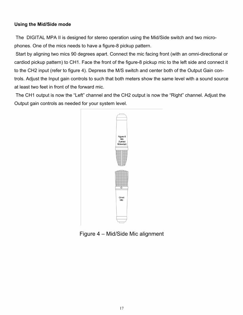
Using the Mid/Side mode
The DIGITAL MPA II is designed for stereo operation using the Mid/Side switch and two micro-
phones. One of the mics needs to have a figure-8 pickup pattern.
Start by aligning two mics 90 degrees apart. Connect the mic facing front (with an omni-directional or
cardiod pickup pattern) to CH1. Face the front of the figure-8 pickup mic to the left side and connect it
to the CH2 input (refer to figure 4). Depress the M/S switch and center both of the Output Gain con-
trols. Adjust the Input gain controls to such that both meters show the same level with a sound source
at least two feet in front of the forward mic.
The CH1 output is now the “Left” channel and the CH2 output is now the “Right” channel. Adjust the
Output gain controls as needed for your system level.
Figure 4 – Mid/Side Mic alignment

18
WARRANTY INFORMATION Limited Warranty
Applied Research and Technology will provide warranty and service for this unit in accordance with the following warrants: Applied Research and Technology (A R T) warrants to the original purchaser that this product and the components thereof will be free from defects in workmanship and materials for a pe-riod of three years from the date of purchase. Applied Research and Technology will, without charge, repair or replace, at its option, defective product or component parts upon prepaid de-livery to the factory service department or authorized service center, accompanied by proof of purchase date in the form of a valid sales receipt.
Exclusions
This warranty does not apply in the event of misuse or abuse of the product or as a result of unauthorized alterations or repairs. This warranty is void if the serial number is altered, de-faced, or removed. A R T reserves the right to make changes in design or make additions to or improvements upon this product without any obligation to install the same on products previously manufac-tured. A R T shall not be liable for any consequential damages, including without limitation damages resulting from loss of use. Some states do not allow limitations of incidental or consequential damages, so the above limitation or exclusion may not apply to you. This warranty gives you specific rights and you may have other rights, which vary from state to state. For units purchased outside the United States, an authorized distributor of Applied Research and Technology will provide service.

19
SERVICE
The following information is provided in the unlikely event that your unit requires service. 1) Be sure that the unit is the cause of the problem. Check to make sure the unit has power, all
cables are connected correctly, and the cables themselves are in working condition. You may want to consult with your dealer for assistance in troubleshooting or testing your par-ticular configuration.
2) If you believe the ART unit is at fault, go to www.artproaudio.com. You may contact Cus-
tomer Service for more assistance, or directly request a Return Authorization for service in the “resources” area of the website.
3) If you are returning the unit for service, pack the unit in its original carton or a reasonable
substitute. The original packaging may not be suitable as a shipping carton, so consider put-ting the packaged unit in another box for shipping. Print the RA number clearly on the out-side of the shipping box.
4) Include, with your unit, a note with the RA number and your contact information including a
daytime phone number, preferably attached to the top of the unit.
20
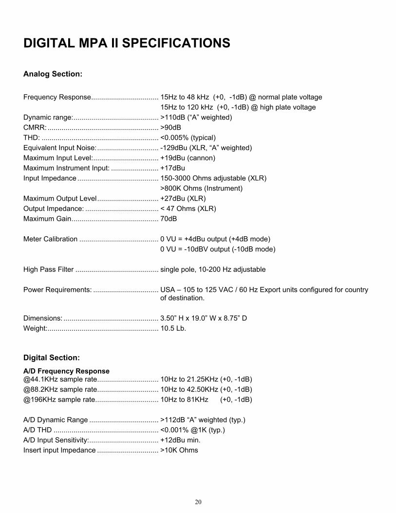
DIGITAL MPA II SPECIFICATIONS
Analog Section:
Frequency Response.................................. 15Hz to 48 kHz (+0, -1dB) @ normal plate voltage 15Hz to 120 kHz (+0, -1dB) @ high plate voltage Dynamic range:........................................... >110dB (“A” weighted) CMRR: ........................................................ >90dB THD: ........................................................... <0.005% (typical) Equivalent Input Noise:............................... -129dBu (XLR, “A” weighted) Maximum Input Level:................................. +19dBu (cannon) Maximum Instrument Input: ........................ +17dBu Input Impedance ......................................... 150-3000 Ohms adjustable (XLR) >800K Ohms (Instrument) Maximum Output Level............................... +27dBu (XLR) Output Impedance: ..................................... < 47 Ohms (XLR) Maximum Gain............................................ 70dB Meter Calibration ........................................ 0 VU = +4dBu output (+4dB mode) 0 VU = -10dBV output (-10dB mode) High Pass Filter .......................................... single pole, 10-200 Hz adjustable Power Requirements: ................................. USA – 105 to 125 VAC / 60 Hz Export units configured for country
of destination. Dimensions: ................................................ 3.50” H x 19.0” W x 8.75” D Weight:........................................................ 10.5 Lb.
Digital Section: A/D Frequency Response @44.1KHz sample rate............................... 10Hz to 21.25KHz (+0, -1dB) @88.2KHz sample rate............................... 10Hz to 42.50KHz (+0, -1dB) @196KHz sample rate................................ 10Hz to 81KHz (+0, -1dB) A/D Dynamic Range ................................... >112dB “A” weighted (typ.) A/D THD ..................................................... <0.001% @1K (typ.) A/D Input Sensitivity:................................... +12dBu min. Insert input Impedance ............................... >10K Ohms