Embed Size (px)
Citation preview

EN
DIGITAL MIXING CONSOLE
TF StageMix V4.0 User's Guide

Introduction
IntroductionThank you for downloading the TF StageMix app (hereafter referred to as "StageMix") for iPad. StageMix allows you to use your iPad to wirelessly control the parameters of your Yamaha TF series digital mixing console. StageMix gives the sound engineer the freedom to control parameters of the TF series console from the stage, while listening to the results from the vantage point of the performers. Because of its simple touch interface that offers a direct style of interaction with the console, we think you'll find that StageMix will help you set up faster and more dynamically than ever before. You can download the latest version of the TF series console firmware from the Yamaha Pro Audio website. http://www.yamahaproaudio.com/
Note• The software and this document are the exclusive copyrights of Yamaha Corporation. • Copying or modifying the software or reproduction of this document, by any means, whether in whole or in part, is expressly
forbidden without the written consent of Yamaha Corporation. • Yamaha Corporation makes no representations or warranties with regard to the use of the software and documentation and
cannot be held responsible for the results of the use of the software and this document. • Copying of commercially available music sequence data and/or digital audio files is strictly prohibited except for your personal
use.• Illustrations of product screens that appear in this document are for instructional purposes, and may appear somewhat different
from the screens that are displayed on your computer. • Information about system software and changes to certain product functions or specification due to updates to the software can
be found in the related documentation. • Apple, the Apple logo, and iPad are trademarks of Apple Inc., registered in the U.S. and other countries. • The company names and product names in this document are the trademarks or registered trademarks of their respective
companies.
User's GuideTF StageMix- 2 -

Table of contents
Table of contentsIntroduction .......................................................................................................... 2Note............................................................................................................................................................... 2
System compatibility information ........................................................................ 4
Wireless settings.................................................................................................... 5
Preparation............................................................................................................ 6Configuring the console's network settings..................................................................................................... 6Configuring iPad network settings .................................................................................................................. 6StageMix settings ........................................................................................................................................... 8
Screen areas ........................................................................................................... 9HOME screen.................................................................................................................................................. 9
SELECT MIXER screen.............................................................................................................................. 10UTILITY screen......................................................................................................................................... 11CUSTOM FADER BANK screen................................................................................................................. 12USER DEFINED BUTTONS screen............................................................................................................. 13RECORDER screen ................................................................................................................................... 15SETUP screen .......................................................................................................................................... 17
SCENE screen ............................................................................................................................................... 27INPUT screen................................................................................................................................................ 28EQ screen ..................................................................................................................................................... 30GATE screen ................................................................................................................................................. 32COMP screen ............................................................................................................................................... 33SEND TO screen ........................................................................................................................................... 35GEQ screen................................................................................................................................................... 36DELAY screen................................................................................................................................................ 37FX screen (FX1/2, InsFX1–6) ......................................................................................................................... 38NAME screen................................................................................................................................................ 40
Troubleshooting .................................................................................................. 41
User's GuideTF StageMix- 3 -

System compatibility information
System compatibility information• Apple iPad 4 and later• iOS 10 and later• Yamaha TF Series Digital Mixing Console V4.0 and later• Wireless access point (802.11g, 2.4GHz compatible, 802.11n, 5GHz recommended)• CAT5 Ethernet cable (used to connect the console to the wireless access point)
User's GuideTF StageMix- 4 -

Wireless settings
Wireless settingsConfigure your wireless access point, and refer to its operating instructions if necessary. Your wireless access point should not require any special settings in order to use StageMix, however, we recommend that you configure the access point to require a password for wireless connections for added security.The following briefly describes the steps needed to configure your wireless access point.
1. Assign the desired wireless network name (also called an "SSID") to the wireless access point.
2. Select a wireless security protocol (WPA, WPA2, etc.) and assign a password to the wireless access point.
3. Configure the wireless access point to use the desired wireless mode (802.11g or 802.11n).
4. When using 802.11n, you may be able to select whether the access point uses the 2.4GHz or 5GHz wireless band.
5. If your wireless access point supports Auto Channel Selection, enable it.This allows the wireless access point to automatically select the wireless channel with the least amount of interference.
For the fastest wireless communication between the iPad and the wireless access point, we recommend configuring the access point to use the 802.11n wireless mode at 5GHz. Additionally, using external antennas with your wireless access point (if supported) will make wireless connections to the access point more reliable.
User's GuideTF StageMix- 5 -

Preparation
PreparationConfiguring the console's network settings1. Use a CAT5 Ethernet cable to connect the console to the wireless access point.
Older access points that do not support Auto MDI-X require that you connect the console using a crossover cable. For access points that support Auto MDI-X (most do today), you can use either a straight cable or a crossover cable.
2. Make sure the Ethernet cable from the console is connect to a LAN port of the wireless access point.Do not connect the console to the wireless access point's WAN port.
Configuring iPad network settingsYou can configure the iPad to receive network settings via DHCP, or assign them manually.
Configuring iPad network settings using DHCPDHCP is a network protocol that allows a device to receive its network settings from a DHCP server. Use the following procedure to configure the iPad to use DHCP.
Operation1. Open the [Settings] screen on the iPad.
2. Tap [Wi-Fi] and then select the network name (SSID) of your wireless access point.
3. Tap the blue mark to the right of the current network to display details about the network connection.
4. Tap [DHCP], and then confirm that the iPad has received settings for IP address, subnet mask, router, and DNS.
5. You can tap [Renew Lease] to force the iPad to receive the network settings from the DHCP server again.
6. When finished, press the home button on the iPad.
NOTE• Make sure the subnet assigned to the iPad matches the subnet assigned to the console.• If the iPad does not receive network settings from the DHCP server even after you tap [Renew Lease], check the settings of the DHCP server.
You can also configure network settings for the iPad manually.
User's GuideTF StageMix- 6 -

Preparation
Configuring iPad network settings manually
Operation1. Open the [Settings] screen on the iPad.
2. Tap [Wi-Fi] and then select the network name (SSID) of your wireless access point.
3. Tap the blue mark to the right of the current network to display details about the network connection.
4. Tap [Static], and then configure each setting as described in the following steps.
5. IP address: Refer to the IP address of the console, and enter a comparable IP address by changing the last set of four numbers.For example, if the console's IP address is "192.168.0.128", you could assign "192.168.0.127" to the iPad.
6. Subnet mask: Enter "255.255.255.0".
7. Router: Enter the IP address of the wireless access point.Typically this is printed on a label on the device itself or is listed in the device's operating instructions.
8. Router: Enter the IP address of the wireless access point. (The same address as entered in step 7.)
9. When finished, press the home button on the iPad.
User's GuideTF StageMix- 7 -

Preparation
StageMix settingsStart StageMix.
The SELECT MIXER screen is displayed. The following are available from this screen.• OFFLINE: allows you to view a demo of the StageMix features and user interface.• CONNECT: allows you to select and connect to a TF series console that is connected to the same network.
Offline demo modeTap [OFFLINE] on the SELECT MIXER screen to use StageMix in demo mode, without connecting to a console. When using this mode, you cannot use level meters, access scenes, etc.
Connecting to the consoleIf the iPad and console are connected to the same network, select the console and tap [CONNECT] to connect to the console.When the maximum number of TF Editor and TF StageMix sessions (total: 3) are already connected to the TF series console, a "restricted" mark is displayed to the left of the IP address. When you select a TF series console that has a "restricted" mark displayed next to it and tap the CONNECT button, a message is displayed that indicates you cannot connect to the console.
After StageMix has received the necessary data from the console, the mixer window is displayed and you are ready to begin using StageMix.If StageMix cannot connect to the console, refer to the Troubleshooting section (page 41).
Network switching (V3.0 and later)If using iOS 9.3 and later with TF StageMix V3.0 and later, you can connect to a network using a wired connection in addition to a wireless connection. A Lightning to USB 3 Camera Adapter (or USB-C to USB Adapter) and an USB Ethernet Adapter are required to use a wired connection.You can switch between a wireless and wired connection when offline; you cannot switch while online.
User's GuideTF StageMix- 8 -

Screen areas
Screen areasHOME screenThe HOME screen is the main screen of StageMix. It is displayed each time you start StageMix.You can return to this screen by tapping [HOME] in the TOOLBAR area.
METER areaDisplays input level, output level, and fader levels. In SENDS ON FADER mode, it displays send levels.
1 ONLINE buttonDisplays the SELECT MIXER screen (page 10).When StageMix is connected to a console, the name of the console is displayed here.When no console is connected (i.e., offline demo mode), "OFFLINE" is displayed.
2 UTILITY buttonTap to display the UTILITY screen (page 11).
3 SETUP buttonDisplays the SETUP screen (page 17).
4 Meter displayDisplays all input and output meters. The channel names for each block are displayed in the bottom area of the meter.Meters are displayed in green for up to -21dB, yellow for up to -4dB, and in red for levels higher than -3dB.You can change the meter point in the SETUP screen (page 17).Note that the meter point for the MONITOR channel is always pre-fader.
The fader level for each channel is indicated by a white line. A thick white line is displayed when the fader is at the nominal (0dB) level.If a channel is turned off, the background of the meter is displayed in black and the meter itself is displayed in gray.
The area displayed in the details area is indicated in the METER area by a white box. You can drag this box left and right to display other channels in the details area. You can switch the details area between displaying the Custom Fader Bank and the typical display by swiping up on this area. You can also switch between the Custom Fader Bank and the typical display by pressing and holding down the white box.When the Custom Fader Bank is displayed, only the channel name of the top of each block is displayed at the bottom of the meter. However, when the top channel is blank or ROLL OUT, no name is displayed.
In SENDS ON FADER mode, each channel's send level is displayed here. In this case the fader level bar is displayed in the color assigned to the destination channel.
METER area
Details area
Overview strip area
TOOLBAR area
User's GuideTF StageMix- 9 -

Screen areas
SELECT MIXER screen
1 Network switching buttonSwitches the network connection between wireless and wired connection.A Lightning to USB 3 Camera Adapter (or USB-C to USB Adapter) and an USB Ethernet Adapter are required to use a wired connection.You can switch between a wireless and wired connection when offline; you cannot switch while online.
2 Device listThe name of any consoles on the network that StageMix can connect to are displayed here.Tap the name of the desired console to select it.If multiple consoles are discovered, you can scroll this area up and down to view the names of other consoles.When the maximum number of TF Editor and TF StageMix sessions (total: 3) are already connected to the TF series console, a "restricted" mark is displayed to the left of the IP address. When you select a TF series console that has a "restricted" mark displayed next to it and tap the CONNECT button, a message is displayed that indicates you cannot connect to the console.
3 CONNECT buttonConnects StageMix to the console that is selected in the device list.
4 OFFLINE buttonSwitches StageMix to offline demo mode.If a StageMix is connected to a console, it is disconnected.
User's GuideTF StageMix- 10 -

Screen areas
UTILITY screen
1 MUTE Master buttonThese are master buttons for each mute group. The buttons light up red when turned on.The 1 INPUT button mutes all input channels at once.The 2 FX button mutes all FX modules at once. It bypasses the insertion effect for channels AUX9/10 to AUX19/20.Buttons 3 to 6 mute all channels assigned to the corresponding mute group. Group assignment settings are specified in the TF series main unit. Buttons 3 to 5 are labeled with the mute group specified in the TF series main unit.
2 Custom Fader buttonDisplays the CUSTOM FADER BANK screen. (page 12)
3 User Defined Buttons buttonDisplays the USER DEFINED BUTTONS screen. (page 13)
4 Recorder buttonDisplays the RECORDER screen. (page 15)
User's GuideTF StageMix- 11 -

Screen areas
CUSTOM FADER BANK screen
1 Fader buttonsAllow you to select which fader will be configured.
2 Channel buttonsDetermine which channel will be assigned to the fader you selected for 1.If you select a channel that has already been assigned, the assignment is canceled. If you select None, the channel is not assigned to a fader.If you select ROLL OUT, when you select DCA in the Home screen, channels assigned to the selected DCA are displayed in the order they were assigned. When you select an item other than DCA in the Home screen, channels assigned to the last DCA you selected are displayed.You can assign ROLL OUT to multiple faders in one operation. For example, if you assign ROLL OUT to fader 5 when ROLL OUT has already been assigned to fader 1, ROLL OUT will be assigned to faders 2-4 automatically. If other functions have already been assigned to faders 2-4, a message is displayed asking whether if you want to assign ROLL OUT to faders 2-4.
CUSTOM FADER BANK screen menuThe following items are available in the CUSTOM FADER BANK screen's context menu.Import: Allows you to import TF series CUSTOM FADER BANK settings.Clear All: Allows you to clear all fader assignments (set them all to None) in one operation.Default: Allows you to return all fader assignments to their default settings.
User's GuideTF StageMix- 12 -

Screen areas
USER DEFINED BUTTONS screenThis screen is used to define User Defined Buttons for StageMix.
1 Button setting buttonsTapping one of these buttons displays a screen (Function Selection screen) used to select functions assigned to respective USER DEFINED BUTTONS.
Function Selection ScreenTapping the Label text box enables label text to be entered directly via the keyboard. Up to six alphanumeric characters can be entered. The Label field can also be left blank.If the Function function is selected, then Parameter1 selection choices are displayed. If the Parameter1 function is selected, then Parameter2 selection choices are displayed. If there are no parameter selection choices available for the selected function, then no selection choices are displayed for Parameter1 or Parameter2.
Functions Assignable to USER DEFINED BUTTONS
Fuction Parameter1 Parameter2 DescriptionNo Assign - - No functions are assigned.
AutomixerBypass Group a, Group b Bypasses the AUTOMIXER specified for Parameter2.
Specific CH CH1–CH8 Switches the AUTOMIXER specified for Parameter2 ON/OFF.
CH ON Specific CH All channels Switches the channel specified for Parameter2 ON/OFF.
CH Select
Inc -Successively selects channels in the order specified for Parameter1.
Dec -
Specific CH All channels Selects the channel specified for Parameter2.
CUE Specific CH All channels Switches the CUE specified for Parameter2 ON/OFF.
Effect Bypass FX1–2, INS FX1–6 Bypasses the effect specified for Parameter2.
User's GuideTF StageMix- 13 -

Screen areas
Meter Peak Hold ON - Switches the meter peak hold function ON/OFF.
MonitorOutput - Switches the monitor output ON/OFF.
Source Select STEREO, SUB, ST IN1–2, USB 33/34, Playback Selects the monitor source specified for Parameter2.
Mute Master
MUTE 1 (INPUT), MUTE 2 (FX), MUTE GROUP 3, MUTE GROUP 4, MUTE GROUP 5, MUTE GROUP 6
- Switches all applicable mute groups specified for Parameter1 ON/OFF.
OscillatorOscillator ON - Switches the oscillator ON/OFF.
Specific CH AUX1–20, STEREO L, STEREO R, SUB
Switches the oscillator assignment for the channel selected for Parameter2 ON/OFF.
Page ChangeBookmark -
Holding down the button for 2 seconds or more bookmarks the currently displayed screen. Holding down the button for less than 2 seconds recalls the saved screen.
Bookmark with “SEL” - Bookmarks the screen together with the selected channels. Otherwise it functions the same as Bookmark above.
Recorder Transport
Play/Pause Functions the same as the Play/Pause button in the RECORDER screen.
Stop Functions the same as the Stop button in the RECORDER screen.
Next Functions the same as the Next button in the RECORDER screen.
Previous Functions the same as the Previous button in the RECORDER screen.
Rec Functions the same as the Rec button in the RECORDER screen.
Auto Rec Stops recording and starts recording in a new file.
Rec & Start Starts recording with a single tap.
Scene
Inc - Selects the SCENE for the next larger number.
Dec - Selects the SCENE for the next smaller number.
Store - Stores the current setting by overwriting the setting for the selected number.
Recall - Recalls the SCENE for the selected number.
Inc Recall - Recalls the SCENE for the next larger number.
Dec Recall - Recalls the SCENE for the next smaller number.
Direct Recall/Store A00–A99, B00–B99Recalls the SCENE for the number specified for Parameter2. Holding down the button for 2 seconds or more stores the current setting by overwriting the previous setting for that number.
NOTE• Separate functions are assigned in the USER DEFINED BUTTONS screen above than for the [USER DEFINED KEYS] on the TF series
main unit. Functions assigned via the USER DEFINED BUTTONS screen can be executed using the Menu button (page 25).• Automixer, Meter (Peak Hold ON), Monitor, and Oscillator functions are operated via the TF series main unit. Those functions are not
available in TF StageMix.
Fuction Parameter1 Parameter2 Description
User's GuideTF StageMix- 14 -

Screen areas
RECORDER screenThis screen is used to operate the Recorder on the main unit.
1 Directory up buttonMove to the directory next level up the current directory.
2 Current directory informationDisplays the directory path for the current USB storage device directory.
3 Recording level meterDisplays the recording volume level.
4 Recording level sliderSets the recording volume level.
5 Song name listDisplays a list of song files in the current directory and corresponding sub-directories.Tapping on the sub-directory displays that directory.Tapping on a column heading sorts the list based on that heading.Song files can be selected by tapping on the file name.Tapping anywhere other than the checkbox for the selected song will play or pause the selected song.If the checkbox is tapped so that a check mark is displayed, then that file is played when playing ALL songs.The file name is displayed in the File Name column.Artist information is displayed in the Artist column (only for MP3 files). The song length is displayed in the Time column.
6 Song file information display/indicatorWhenever an MP3 or WAV file is played, this displays the file name and the location within the file being played.During recording, it displays the WAV file name and the recording elapsed time.
7 Play mode setting buttonSpecifies the loop play mode setting.Each tap changes the mode as follows.
: Plays one song one time (SINGLE play mode).
: Plays one song repeatedly (SINGLE REPEAT play mode).
: Plays all songs marked with a check mark one time (ALL play mode).
: Plays all songs marked with a check mark repeatedly (ALL REPEAT play mode).
User's GuideTF StageMix- 15 -

Screen areas
8 PREVIOUS buttonStarts playing at the beginning of the current or previous song when tapped.
9 STOP buttonStops recording or playing.
0 PLAY/PAUSE buttonPlays or pauses the current song.
A NEXT buttonStarts playing at the beginning of the next song.
B RECORD buttonActivates the standby mode for recording.
C Play volume level meterDisplays the play volume level.
D Play volume level sliderSets the play volume level.
User's GuideTF StageMix- 16 -

Screen areas
SETUP screenAllows you to configure the StageMix app.The SETUP screen is divided into the PREFERENCE, LICENSE, and ABOUT screens. You can switch between screens by tapping the desired screen name at the bottom of the SETUP screen.
PREFERENCE screen
GENERAL area
1 Fader/Pan DelayAllows you to adjust the amount of delay between when you adjust a control and when the adjustment is applied.This setting helps prevent unintended fader or pan movement.Range: 0.00–0.50sec (0.01sec increments)
2 Cue ModeAllows you to select the desired cue mode.Mix Cue: Enables cue for multiple channels.Last Cue: Enables cue for the last channel selected.
3 [SEND SEL] > [CUE] LinkWhen ON, the CUE follows the selected destination for the SENDS ON FADER mode.
4 Enable Phantom Power SwitchingAllows you to enable and disable the console's +48 phantom power feature.When phantom power is enabled, this switch is displayed in red. When phantom power is disabled, the +48V buttons on the INPUT screen are disabled.
5 Fader 0dB DetentIf this feature is turned on when you adjust a fader or pan, this feature stops fader and pan operations at 0 dB or center. You can then continue to drag it as desired.
6 Display Delay ScaleYou can select the desired units (frames, meters, feet, milliseconds) that are displayed as the delay time in the Processing area (page 20) of the HOME screen.
7 Frame RateSelects the frame rate (in numbers of frames) for the delay setting of the OUTPUT DELAY effect type.
CONFIRMATION area
8 Pre FaderDetermines whether a confirmation message is displayed when you tap the PRE button to turn it on (i.e., when you switch to pre-fader mode) in SENDS ON FADER mode.
9 RecallDetermines whether a confirmation message is displayed in the SCENE screen when you recall a scene.
0 StoreDetermines whether a confirmation message is displayed in the SCENE screen when you save a scene.
User's GuideTF StageMix- 17 -

Screen areas
A INPUT SelectWhen this item is turned on, a confirmation message is displayed when you change the input source on the INPUT screen.
CH SELECT area
B StageMix Follows ConsoleDetermines whether the channel you select on the console is also selected in StageMix.
C Console Follows StageMixDetermines whether the channel you select in StageMix is also selected on the console.
METERS area
D Input Meter PointDetermines the input level metering point.Pre HPF: After the head amp; before the HPFPre Fader: Before the faderPost On: After the [ON] key
E Output Meter PointDetermines the output level metering point.Pre EQ: Before the EQPre Fader: Before the faderPost On: After the [ON] key
RTA area
F Peak Hold Mode Determines the type of peak hold displayed for RTA. Freeze: The RTA display freezes when you turn the Hold button on. The display refreshes when you turn the Hold button
off. All Peaks: The maximum value of all RTA frequency bands are displayed in red. High Peak: The one frequency band with the highest value is displayed in red.
G Input GainAllows you to adjust the mic input gain of the iPad used for RTA.Available settings: -24dB, -12dB, 0dB, 12dB, 24dB
H Number of BandsDetermines the number of frequency bands displayed by RTA.Available settings: 61-band, 121-band
LICENSE screen
Displays license information about the software used by the StageMix app.
User's GuideTF StageMix- 18 -

Screen areas
ABOUT screen
Displays version information for the StageMix app and the connected console.
User's GuideTF StageMix- 19 -

Screen areas
Details area
Channel strips for 8 channels are displayed in the details area. You can scroll left and right to display the channel strips for other channels by swiping left or right on an inactive area of the screen.
Processing area
Fader area
CH Name area
User's GuideTF StageMix- 20 -

Screen areas
Processing area
Displays each channel's EQ, INPUT, GATE, COMP, SEND TO, GEQ, SEND PAN (when using SENDS ON FADER mode), DELAY and FX. The type of information displayed here varies depending on the type of channel. Tapping the processing area displays the corresponding setting screen. (The Send Pan display does not have a corresponding setting screen, but the values can be changed by sliding a finger over the icon.)You can swipe left and right in this area to display other information. The type of information displayed in the processing area changes for all channels.The type of information that can be displayed in this area for each type of channel is explained below.
Fader area
Allows you to adjust the fader and cue for each channel.
1 ON buttonTurns the channel on and off. This button lights when the channel is turned on.It flashes when a mute group is turned on. Tap the button while it is flashing to turn the mute off.Additionally, if a DCA channel is turned off, the ON button of channels included in the DCA channel flash. In this case, tapping the button has no effect.
2 Fader valueDisplays the value of the current fader level. You can tap the value and then increase and decrease it by tapping the up and down arrows.
CH 1–32 CH 33–40 ST IN1L–2R
FX1L–2R DCA1–8 STEREO AUX1–8 AUX 9/10–
AUX 19/20 SUB MON MATRIX
Input – – – – – – – –
EQ – –
Gate – – – – – – – – – –
Comp – – – – – –
GEQ – – – – – – – – –
Send Pan – – –
Send To – – – – – – –
Delay – – – – – – – – –
FX – – – FX1–FX2 – – – InsFX1–InsFX6 – – –
NOTE• When the MATRIX channel is set to "stereo", "Send Pan" will be displayed in STEREO AUX1-8, AUX9/10-19/20 and SUB.• The "Display Delay Scale" setting in the General area of the PREFERENCE screen allows you to select the desired units (frames, meters, feet,
milliseconds) that are displayed in the MATRIX channel DELAY box. (page 17)
User's GuideTF StageMix- 21 -

Screen areas
3 FaderDrag the fader's knob up and down to adjust the fader level.The fader stops at the nominal level (0dB); you can then continue to drag it up or down as desired.You can drag the fader left and right and then up and down to adjust it more precisely.You can adjust multiple faders at the same time.
4 Meter displayDisplays the post-fader channel level.Two meters are displayed for MONITOR channels and for channels linked as a stereo pair.Meters are not displayed for DCA channels.
5 CUE buttonTurns the channel's cue on and off. This button lights up when the cue is turned on.The CUE button is not displayed for the MONITOR channel.
CH Name area
Allows you to adjust the channel's pan/balance, and displays the channel's number, name, icon, and color.
1 Pan/balance sliderDrag left and right to adjust the pan or balance of the channel.The control stops at the center position; you can then continue to drag it left or right as desired.When the pan or balance is set to the center position, a round icon is displayed. You can also double-tap this area to set the pan or balance to the center position.You can adjust pan/balance for multiple channels at the same time.
2 Channel displayDisplays the channel number, name, icon, and color.
Overview strip area
The STEREO channel strip is normally displayed in the overview strip area. When using SENDS ON FADER mode, the destination AUX channel, SUB channel, or MATRIX channel strip is displayed here.You can switch to SENDS ON FADER mode by tapping a channel number displayed on the left side of the strip. The selected channel will be highlighted in the channel's color. Tapping on OFF at the bottom or the selected channel number restores the regular mode.
NOTE• If you have adjusted the Fader/Pan Delay setting on the PREFERENCE screen (page 17), the fader value is displayed in light blue when
the fader can be adjusted.• If Fader 0dB Detent on the PREFERENCE screen is turned off (page 17), the value fader does not stop at the nominal point.
User's GuideTF StageMix- 22 -

Screen areas
In the SENDS ON FADER mode, holding down the selected channel displays a pop-up menu for copying or pasting the send level for the corresponding channel.If you enter SENDS ON FADER mode while an FX channel is selected, nothing is displayed here.
Copying the Send Level for the Selected Destination Channel and Pasting it for Another Channel1. Tap the destination channel from which the send level is to be copied.
The mode switches to the SENDS ON FADER mode.
2. Hold down the destination channel from which the send level is to be copied.A pop-up menu is displayed for copying or pasting the send level for the channel that was held down.
3. Tap Copy.
4. Hold down the channel where the send level is to be pasted.A pop-up menu is displayed for copying or pasting the send level for the channel that was held down.
5. Tap Paste.
User's GuideTF StageMix- 23 -

Screen areas
SENDS ON FADER screen
Allows you to use the faders to adjust the send level for each channel.
In SENDS ON FADER mode, the details area changes to display SENDS ON FADER information.Note, however, that the display does not change for channels that have no send destination.
1 Send pan sliderDisplayed when you have selected a stereo channel as the destination of a send. Allows you to adjust the panning of the send. Not displayed when the destination of the send is FX, SUB.
2 Send ON buttonTurns the send on and off. This button lights when the send is turned on.
3 Send level faderAllows you to adjust the send level of the corresponding channel. You can tap the value and then increase and decrease it by tapping the up and down arrows.
4 FaderAllows you to adjust the level of the send.
5 PRE buttonDetermines whether the pre-fader or post-fader signal is sent. This button lights when it is turned on.On: Before the faderOff: After the faderNot displayed when the destination of the send is SUB or MATRIX.
6 CH NAME displayDisplays the channel's number, name, icon, and color.
User's GuideTF StageMix- 24 -
Screen areas
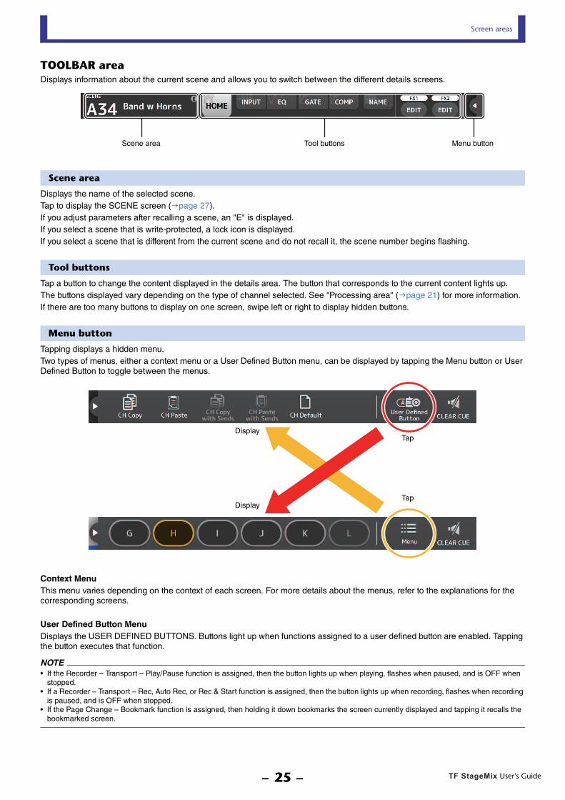
TOOLBAR areaDisplays information about the current scene and allows you to switch between the different details screens.
Scene area
Displays the name of the selected scene.Tap to display the SCENE screen (page 27).If you adjust parameters after recalling a scene, an "E" is displayed.If you select a scene that is write-protected, a lock icon is displayed.If you select a scene that is different from the current scene and do not recall it, the scene number begins flashing.
Tool buttons
Tap a button to change the content displayed in the details area. The button that corresponds to the current content lights up.The buttons displayed vary depending on the type of channel selected. See "Processing area" (page 21) for more information.If there are too many buttons to display on one screen, swipe left or right to display hidden buttons.
Menu button
Tapping displays a hidden menu.Two types of menus, either a context menu or a User Defined Button menu, can be displayed by tapping the Menu button or User Defined Button to toggle between the menus.
Context MenuThis menu varies depending on the context of each screen. For more details about the menus, refer to the explanations for the corresponding screens.
User Defined Button MenuDisplays the USER DEFINED BUTTONS. Buttons light up when functions assigned to a user defined button are enabled. Tapping the button executes that function.
NOTE• If the Recorder – Transport – Play/Pause function is assigned, then the button lights up when playing, flashes when paused, and is OFF when
stopped.• If a Recorder – Transport – Rec, Auto Rec, or Rec & Start function is assigned, then the button lights up when recording, flashes when recording
is paused, and is OFF when stopped.• If the Page Change – Bookmark function is assigned, then holding it down bookmarks the screen currently displayed and tapping it recalls the
bookmarked screen.
Scene area Tool buttons Menu button
DisplayTap
TapDisplay
User's GuideTF StageMix- 25 -

Screen areas
HOME screen menuThe following items are available in the HOME screen's context menu.CH Copy: Copies the settings of the current channel.CH Paste: Pastes settings from the copied channel and applies them to the selected channel.CH Copy with Sends: Copies settings for the selected channel, including the send level sent to the channel.CH Paste with Sends: Pastes channel settings copied to the selected channel, including the send level sent to the channel.CH Default: Resets the settings of the current channel to their default values.Clear CUE: Turns off all cue selections.
CH Copy with Sends and CH Paste with Sends buttons are only enabled when an FX, AUX, SUB, or MATRIX channel is selected.
User's GuideTF StageMix- 26 -

Screen areas
SCENE screenAllows you to manage previously saved mixer setups, or "Scenes".
1 Scene list selection buttonAllows you to switch between the available Scene lists.SCENE A: Displays the Scenes stored in Scene list A.SCENE B: Displays the Scenes stored in Scene list B.
2 Scene listDisplays the Scenes saved in the selected Scene list.You can tap a header in the list to sort the items by that header. (List items cannot be sorted by "Information".)To select a Scene, simply tap it. The selected Scene is highlighted, and can then be recalled.A green triangle is displayed next to the Scene that is currently recalled.The fade time setting for the scene is displayed in the Fade Time column. A icon is displayed if fade time is enabled. Fade time settings are specified in the TF series main unit.
Locked scenes are indicated by a lock icon and cannot be edited.
The date on which the Scene was last saved is displayed in the Date column.
3 Store buttonSaves the current mixer setup as a Scene using the number selected in the Scene list.You can tap this button to edit the title and comments.
4 Recall buttonRecalls the Scene that is selected in the Scene list.
5 Edit buttonYou can tap this button to edit the title and comments.
NOTEIf Store Confirmation on the PREFERENCE screen is turned on (page 17), a confirmation message is displayed before the data is stored. Tap the OK button to save the selected Scene. If Store Confirmation is turned off, the Scene will be saved and no confirmation message will be displayed.
User's GuideTF StageMix- 27 -

Screen areas
INPUT screenDisplayed when you tap the INPUT button in the TOOLBAR area.Allows you to turn phantom power on and off, toggle the signal phase, and adjust input gain.
1 Stereo link selection buttonAllows you to select whether two adjacent mono input channels are linked as a stereo pair, or behave as two separate mono channels. Tap to display the popup menu.OFF: Stereo link is disabled.CH1&2: Stereo link is enabled. When stereo link is enabled, the odd numbered channel is the left side of the stereo pair, and
the even numbered one is the right. The channel numbers displayed in the popup menu depend on the channel whose settings you are editing.
CH2&3: Stereo link is enabled. When stereo link is enabled, the even numbered channel is the left side of the stereo pair, and the odd numbered one is the right. The channel numbers displayed in the popup menu depend on the channel whose settings you are editing.
2 Input selectionAllows you to select the input source selected on console.
3 GainFinderDisplays the input gain level. When adjusting the input gain, adjust it so that the center of the GainFinder lights up. When USB is selected as the console's input, the input's digital gain is displayed here.VIRTUAL will be displayed when there are no I/O devices connected and SLOT is selected as the console's input.
4 +48V buttonTurns phantom power (+48V) to the head amp on and off.On: Phantom power is turned on.Off: Phantom power is turned off.When USB is selected as the console's input, this button is not displayed.This button is disabled when "Enable Phantom Power Switching" on the PREFERENCE screen of the SETUP screen is disabled. (page 17)
5 Φ (phase) buttonAllows you to reverse the input signal phase. When turned on, the input signal's phase is reversed.
6 Gain slidersWhen INPUT is selected as the console's input, the slider adjusts the analog gain of the head amp.The PAD (-24dB) will be switched on or off when the analog gain is adjusted between +17dB and +18dB.When USB is selected as the console's input, the slider adjusts digital gain.
NOTEWhen SLOT is selected as the console's input, analog gain adjustment and the +48V button cannot be used if the HA Control button on the SLOT SETUP screen is not turned on. Additionally, for inputs from a device whose head amp cannot be controlled, the gain slider 6 becomes a digital gain adjustment, and the +48V button 4 is not displayed.
User's GuideTF StageMix- 28 -

Screen areas
7 Level meterDisplays the input's gain adjusted level.
8 Digital gain text boxAllows you to adjust digital gain. The default setting is 0dB. You can tap the value and then increase and decrease it by tapping the up and down arrows.This item is not displayed when USB is selected as the console's input or for the ST IN channel.
9 Gain Unlink buttonDisplayed for stereo channels and for channels that have stereo link turned on.While you are tapping and holding the button, gain for the left and right channels can temporarily be adjusted individually. When you release the button, the gain for both channels can be adjusted together but the difference in gain between the two channels is maintained.
INPUT screen menuThe following items are available in the INPUT screen's context menu.ALL INPUT: Allows you to assign the INPUT jacks as the input source for all input channels.ALL USB: Allows you to assign the USB TO HOST connector as the input source for all input channels.ALL SLOT: Switches all inputs to input sources of Dante network devices that are connected to the NY64-D installed in the
expansion slot.
The input source for the following channels will be changed.
TF5:CH 1–32 (when CH 1–32 are selected)CH 33–40 (when CH 33–40 are selected)
TF3:CH 1–24 (when CH 1–24 are selected)CH 25–32 (when CH 25–32 are selected)CH 33–40 (when CH 33–40 are selected)
TF1/TF-RACK:CH 1–16 (when CH 1–16 are selected)CH 17–32 (when CH 17–32 are selected)
User's GuideTF StageMix- 29 -

Screen areas
EQ screenDisplayed when you tap the EQ button in the TOOLBAR area.Controls the EQ for each channel. 4-band parametric EQ is available for CH 1–32, AUX 1–20, STEREO, and MATRIX. 2-band parametric EQ is available for CH 33-40, STIN1, STIN2, FX1, FX2, and SUB.
1 EQ buttonTurns the EQ on and off.
2 HPF or LPF buttonTurns the HPF (high-pass filter) on and off.Displayed for CH 1–40.For the SUB channel, this button is the LPF (low-pass filter) button.
3 1-knob buttonSwitches between 1-knob EQ mode and manual mode.When using 1-knob mode, the 1-knob level slider is displayed.
4 1-knob level sliderAdjusts the amount of 1-knob EQ applied.
5 EQ mode type selection buttonWhen using 1-knob EQ mode, allows you to select the 1-knob EQ mode type. Select [Vocal] for vocal channels, otherwise select [Intensity].When set to Intensity, you can adjust the EQ to a setting between flat and increased intensity of the EQ settings you made using manual mode.For output channels, Loudness is available. This setting allows you to boost low and high tones.The available modes depend on the channel whose settings you are editing.
In manual mode, you can select the filter type. You can select low-band and high-band filter.For CH 1-40, the available low-band filters are low-shelving type and bell type. For other channels (i.e., for channels that do not have an HPF), the available low-band filters are HPF, low-shelving type, and bell type.The available high-band filters are LPF, high-shelving type, and bell type.
6 EQ output level meterDisplays the EQ output level.
7 EQ graphDisplays the parameter settings of the EQ and filter. As you adjust the settings of each band, the results are reflected in the graph.When using 1-knob EQ mode, you can adjust the 1-knob level slider by dragging it left and right.When using manual mode, you can drag the handles displayed in the graph to adjust the corresponding settings. When using the bell-type filter, you can adjust the Q by pinching the curve on the graph.
User's GuideTF StageMix- 30 -

Screen areas
The parameters for the selected band are displayed in a popup over the handle.
Tapping the icon toggles between showing or hiding the lock icon. Changes to the cutoff frequency and gain values can be disabled by showing the lock icon. The lock icon can be specified separately for each band.
You can return the EQ gain to its default setting by double-tapping the handle.When HPF is turned on, you can drag the HPF handle to adjust the cutoff frequency. You can also adjust HPF independently when using the Intensity mode for 1-knob EQ mode.If you tap an area of the graph where there is no parameter at 0 dB or lower, RTA or a keyboard is displayed. This is useful for understanding the relationship between sound range and frequency.When you open the EQ screen for the first time, a message is displayed asking whether you want to use the iPad mic for RTA display.
If you tap Don't Allow, RTA will not be displayed in the future. If you want to display RTA later, open the iOS Settings app, select Privacy Microphone, and then turn on StageMix.
8 Hold buttonTurn this button on to display the peak value in the RTA display. You can change how the peak is displayed by using the Peak Hold Mode setting in the PREFERENCE screen (page 17). When RTA display is turned off, this button is displayed in gray and is disabled.
EQ screen menuThe following items are available in the EQ screen's context menu.Copy: Copies the EQ parameters of the selected channel to the clipboard.Paste: Pastes the EQ parameters in the clipboard to the selected channel.Compare: Allows you to compare the EQ parameters of the selected channel with the EQ parameters in the clipboard by switching
between the two.Gain Flat: Sets the EQ gain of the current channel to the flat position.Default: Resets EQ settings to their default values.
NOTEStageMix will analyze the sound from the iPad microphone and display RTA.
User's GuideTF StageMix- 31 -

Screen areas
GATE screenDisplayed when you tap the GATE button in the TOOLBAR area.Allows you to configure the noise gate for each channel. When the input signal level is lower than a specified amount (threshold), the output signal is reduced by a specified amount (range). GATE is available for CH 1–32.
1 GATE buttonTurns the gate on and off.
2 Gate input level meterDisplays the gate's input level.
3 Threshold sliderDetermines the level at which the gate is applied.
4 Gate graphDisplays a visual representation of the gate level.
5 Range sliderDetermines the amount by which the signal will be lowered when the gate is applied.
6 Attack sliderWhen the input signal exceeds the threshold, this setting determines how quickly the gate opens.
7 Hold sliderWhen the input signal drops below the threshold, this setting determines how much time passes before the gate closes.
8 Decay sliderAfter the hold time passes, this setting determines how quickly the gate closes.The value here is expressed as the time required for the level to change by 6dB.
9 GR (gain reduction) meterDisplays the amount by which the signal's gain is reduced.
0 OUT (gate output) meterDisplays the gate's output level.
GATE screen menuThe following items are available in the GATE screen's context menu.Copy: Copies the GATE parameters of the selected channel to the clipboard.Paste: Pastes the GATE parameters in the clipboard to the selected channel.Compare: Allows you to compare the GATE parameters of the selected channel with the GATE parameters in the clipboard by
switching between the two.Default: Resets GATE settings to their default values.
User's GuideTF StageMix- 32 -

Screen areas
COMP screenDisplayed when you tap the COMP button in the TOOLBAR area.Allows you to configure the compressor for each channel.
1 COMP buttonTurns the compressor on and off.
2 1-knob buttonSwitches between 1-knob mode and manual mode.
3 1-knob level slider (1-knob mode only)Adjusts the amount of 1-knob compressor applied.Not displayed during manual mode.
4 Compressor input level sliderDisplays the compressor's input level.
5 Threshold sliderDetermines the level at which the compressor is applied.
6 Compressor graphDisplays a visual representation of the current settings.
7 Ratio sliderDetermines the amount of compression that is applied.
8 Attack sliderWhen the input signal exceeds the threshold, this setting determines how quickly the maximum amount of compressor is applied.
9 Release sliderWhen the input signal drops below the threshold, this setting determines how much time passes before the compressor is no longer applied. The value here is expressed as the time required for the level to change by 6dB.
0 Out Gain sliderAdjusts the output level of the compressor.
A Knee buttonDetermines the how gradual or sudden the curve is at the threshold. A soft knee means that compression is applied gradually as the signal exceeds the threshold; a hard knee means a more sudden transition.
B GR (gain reduction) meterDisplays the amount by which the signal's gain is reduced.
User's GuideTF StageMix- 33 -

Screen areas
C OUT (compressor output) meterDisplays the compressor output level.
COMP screen menuThe following items are available in the COMP screen's context menu.Copy: Copies the COMP parameters of the selected channel to the clipboard.Paste: Pastes the COMP parameters in the clipboard to the selected channel.Compare: Allows you to compare the COMP parameters of the selected channel with the COMP parameters in the clipboard by
switching between the two.Default: Resets COMP settings to their default values.
User's GuideTF StageMix- 34 -

Screen areas
SEND TO screenDisplayed by tapping the SEND TO button in the TOOLBAR area.The screen specifies the level sent to the AUX bus from each channel.
1 ON buttonsSwitches the flow sent to each AUX channel ON/OFF.
2 Level slidersAdjusts the level sent to each AUX channel.
3 PRE buttonsSelects whether the signal sent to the AUX channel is sent before or after the fader.On: Before the faderOff: After the fader
4 SEND PAN slidersDisplayed when the sending destination is a stereo AUX bus. It is used to adjust the SEND PAN setting.
User's GuideTF StageMix- 35 -

Screen areas
GEQ screenDisplayed when you tap the GEQ button in the TOOLBAR area.You can use the internal graphic equalizer (GEQ) to process AUX 1–8 and STEREO channel signals.The GEQ is a mono, 12-band EQ. Each band is 1/3 octave wide, with an adjustable gain range of ±15dB.31 bands are available; you can adjust gain for up to 12 bands.
1 GEQ buttonTurns the GEQ on and off.
2 GEQ channel selection buttonsThese buttons are displayed only when configuring the GEQ for stereo AUX buses or the STEREO channels.They are not displayed for mono AUX buses.
: Turns the GEQ left/right channel link on and off.
L/R: Allows you select the left and right GEQ channels. For AUX channels, L and R correspond to the channel pair, such as AUX 1 and 2.
3 EQ graph, RTA display, band selectionDisplays the EQ settings with RTA (real-time analysis).You can tap an area to move the display area and center in on where you tapped the screen.While adjusting a gain slider, the point of the corresponding band is highlighted in pink.
4 Gain slidersAllow you to adjust the gain for the corresponding band. The gain value is displayed above the handle.Double-tap a handle to set the corresponding band's gain to 0dB.Swipe left or right on an empty area to display the gain sliders for other bands.
5 Output level meterDisplays the GEQ output level.
6 Available bands displayDisplays the number of additional bands that you can adjust.
7 Hold buttonTurn this button on to display the peak value in the RTA display. You can change how the peak is displayed by using the Peak Hold Mode setting in the PREFERENCE screen (page 17).
GEQ screen menuThe following items are available in the GEQ screen's context menu.Copy: Copies the GEQ parameters of the selected channel to the clipboard.Paste: Pastes the GEQ parameters in the clipboard to the selected channel.Compare: Allows you to compare the GEQ parameters of the selected channel with the GEQ parameters in the clipboard by
switching between the two.Default: Resets GEQ settings to their default values.
User's GuideTF StageMix- 36 -

Screen areas
DELAY screenThe DELAY screen is displayed by tapping the DELAY button in the TOOLBAR area, with either a MATRIX channel or ST IN channel selected.Here you can adjust the delay time applied the signal output from MATRIX channels or ST IN channels, useful for delay compensation.
1 DELAY buttonTurns the DELAY on and off.
2 Display selection buttonWhen a MATRIX channel is set to "Stereo", select the MATRIX channel that will display the parameters.Two buttons are always displayed on the ST IN channel.
3 LR Link buttonIf switched ON when Stereo is specified for a MATRIX channel, the DELAY on/off and delay time operations for the left/right channels will be linked together when this is turned on. When the delay times are set to a different value, the delay times will operate in linked mode, maintaining the time difference.The LR Link button is always displayed on the ST IN channel (V4.0 and later).
4 DELAY sliderAllows you to adjust the delay time.You can specify the delay time in frames, meters, feet, or milliseconds.
5 DELAY settingDetermines the delay time by specifying frames, distance (meters or feet) or time (milliseconds). Tap a text box to display the keyboard and enter a value.
DELAY screen menuThe following items are available in the DELAY screen's context menu.Copy: Copies the DELAY parameters of the selected channel to the clipboard.Paste: Pastes the DELAY parameters in the clipboard to the selected channel.Default: Resets DELAY settings to their default values.
NOTEFor MATRIX channels, this is displayed only when Stereo is specified for that channel. To switch between "Stereo" and "MONOx2", use the settings on the BUS SETUP screen, located in the SETUP of TF series console.
User's GuideTF StageMix- 37 -

Screen areas
FX screen (FX1/2, InsFX1–6)Allows you to set the type of effect and the effect's parameters.
1 TAP buttonAllows you to adjust the BPM by tapping the button at the desired speed. Available when configuring delay and chorus effects. Corresponds to the [TAP] button on the TF series console.
2 Effect type buttonDisplays the EFFECT TYPE screen, where you can select an effect type.
3 Effect type and nameDisplays the type and library name of the current effect.
4 Parameter slidersAllow you to adjust the parameters available for the current effect.
5 Sync buttonDisplayed for effects that have a tempo setting, such as delays. When this button is turned on, the effect's tempo setting can be controlled with the [TAP] button (1).
6 Bypass buttonAllows you to bypass the effects module.
7 Effects output level meterDisplays the effects output level.
NOTETap the return button of the Overview strip area or the FX1/FX2 EDIT buttons to display the screen immediately before opening the FX screen.
User's GuideTF StageMix- 38 -

Screen areas
EFFECT TYPE screen
Allows you to select the effect type.
FX screen menuThe following items are available in the FX screen's context menu.Copy: Copies the effect parameters of the selected effect to the clipboard.Paste: Pastes the effect parameters in the clipboard to the selected effect.Compare: Allows you to compare the effect parameters of the selected effect with the effect parameters in the clipboard by
switching between the two.Default: Resets the selected effect's settings to their default values.
User's GuideTF StageMix- 39 -

Screen areas
NAME screenDisplayed when you tap the NAME button in the TOOLBAR area.Allows you to set the channel name, icon, and channel color.
1 Name text boxEnter the channel name here.Tap the text box to use the keyboard to enter text. You can enter up to eight alphanumeric characters.
2 CH NAME displayDisplays the channel's number, name, icon, and color. You can flick this area left or right to display other channels.
3 Icon buttonTap to display a list of available channel icons.
4 Category buttonAllows you to select a different category of channel icons.The available categories vary depending on the type of channel.
5 Channel icon listTap to apply the channel icon.You can drag this area up and down to display all of the available icons.
6 Sample Name buttonDisplays a list of commonly used channel names based on the selected channel icon.Tap a sample name to use it as the channel name.
7 Color buttonTap to display a list of channel colors.
Tap the desired color to use that color as the channel color.
User's GuideTF StageMix- 40 -

Troubleshooting
TroubleshootingWireless access point DHCP server setup
1 Use a web browser to access your wireless access point's web administrator page.
2 Enable the wireless access point's DHCP feature.
3 Configure the range of addresses that the DHCP feature will assign to connected devices.
4 Confirm that the IP address assigned to the console is outside of the range of IP addresses that the DHCP feature will assign to connected devices. If it is within this range, change the IP address of the console.For example, if the console's IP address is 192.168.1.2, set the DHCP feature to assign address beginning from 192.168.1.3.
If the console is not displayed in the SELECT MIXER screenIf your wireless access point's IGMP snooping feature is enabled, StageMix may not be able to find the console. Disable your wireless access point's IGMP snooping feature and try again.
Using TF Editor and StageMix togetherWhen computers (running TF Editor) and iPads (running TF StageMix) are connected to the console, the console supports up to three simultaneous connections.Only one computer running TF Editor can connect to the console at a time.
Internet connection error messagesWhen you select a wireless network using your iPad, your iPad may try to access the Internet. If your wireless access point cannot connect to the Internet, a "cannot connect to the Internet" message may be displayed on your iPad and StageMix may not be able to connect to the console. An Internet connection is not needed to connect StageMix to the console, however, you may need to change the settings on your wireless access point so that this message is no longer displayed. If this message is displayed, typically you will need to disable your wireless access point's "redirect feature". For details, refer to your device's operating instructions or contact the manufacturer.
If you cannot move 4 or more faders at the same timeIf the Multitasking Gestures setting of your iPad is turned on, you may not be able to move 4 or more faders at the same time. When using StageMix, make sure to turn the Multitasking Gestures feature off.
1 Open the [Settings] screen on the iPad.
2 Tap [General] and then turn [Multitasking Gestures] off.
If you cannot move 3 or more faders at the same timeIf the Zoom feature with the Accessibility settings of your iPad is turned on, you may not be able to move 3 or more faders at the same time. When using StageMix, make sure to turn the Zoom feature off.
1 Open the [Settings] screen on the iPad.
2 Tap [General] [Accessibility] and then turn [Zoom] off.
If RTA is not displayedWhen you open the EQ screen for the first time, a message is displayed asking whether you want to use the iPad mic for RTA display. If you tap Don't Allow, RTA will not be displayed in the future. If you want to display RTA later, open the iOS Settings app, select Privacy Microphone, and then turn on StageMix.
NOTENot all wireless access points have a DHCP server feature. If yours does not, assign an IP address manually to the iPad.
Published 03/2019 CR-F0
© 2015 Yamaha CorporationManual Development Group
Yamaha Downloadshttps://download.yamaha.com/
Yamaha Pro Audio global websitehttp://www.yamahaproaudio.com/
User's GuideTF StageMix- 41 -