Embed Size (px)
Citation preview
Cisco SeOL-21122-01
C H A P T E R 8
Digital Media and Video Surveillance DesignDigital Media System OverviewThe schools Service Ready Architecture (SRA) network architecture in combination with the Cisco Digital Media System (DMS) creates an environment which streamlines and automates information flow and process throughout school districts.
The evolution of digital communication in the 21st century education environment is transforming processes and empowering educators to develop and deploy “eye-catching”, compelling, and integrated video content.
• Digital media communication in school systems is an extremely effective tool to deliver dynamic and cost effective subject matter to staff and students.
• Using digital media school systems keeps the education community connected, increases awareness, and integrates with safety and security system notifications.
• Integrating digital media technologies assists teacher's curriculum development and professional development.
• Comprehensive digital video systems transform video delivery processes in individual classrooms; school administrator can create customized, on-demand educational video content or even relay live video feed during national events or local emergencies.
Video Surveillance OverviewVideo surveillance has been a key component of safety and security groups for many organizations. As an application, video surveillance has demonstrated its value and benefits countless times by providing real-time monitoring of a facility’s environment, people, and assets as well as by recording events for subsequent investigation, proof of compliance, and audit.
For school systems that need to visually monitor or record events video, surveillance has become more important as the number of security risks increases. In addition to video analytics, the value of video surveillance has grown significantly with the introduction of motion, heat, and environmental sensors.
In a typical school environment, several systems are deployed for disparate applications, such as physical access control, fire and smoke detection, and video surveillance. These applications typically do not communicate with each other and require different management and support personnel. As a result, owners and operators suffer from a lack of operational consistency, interoperability, and capabilities that translate into higher capital and operational costs and limit the return on their investment.
8-1rvice Ready Architecture for Schools Design Guide
Chapter 8 Digital Media and Video Surveillance Design Video Surveillance Overview
Cisco’s solution offers software and hardware to support video transmission, monitoring, recording, and management. Cisco video surveillance solutions work in unison with the advanced features and functions of the IP network infrastructure—switches, routers, and other network security devices—to enable secure, policy-based access to live and recorded video.
Cisco Digital Media System ArchitectureCisco has developed a comprehensive, scalable, and network-centric DMS architecture that is built on three major digital application components. Each application is specifically designed to address key challenges, regardless of how or where the digital content is designed and developed. The multifunction management and adaptive media system is common to these three applications:
• Desktop video—Interactive education training application that allow students to watch instructional videos on-demand or via live streaming. Students can use classroom PCs to navigate a Cisco Video Portal database to securely access relevant training video content.
• Enterprise TV—While the targeted users for desktop video applications are individuals or group of students, enterprise TV expands the same video capability to a larger audience and so extends the classroom. Live or on-demand pre-recorded training video can be broadcast in a classroom. In addition to internally developed video material, district and school administration can also enable live educational TV programming like science, discovery, etc.
• Digital signage—Enables innovative ways to publish content and information that improves the user experience, allows dynamic updates, and increases campus safety and security. Some of the common digital signage use cases in schools system include announcing school and district news, major events, classroom assignments, PTA meetings, etc.
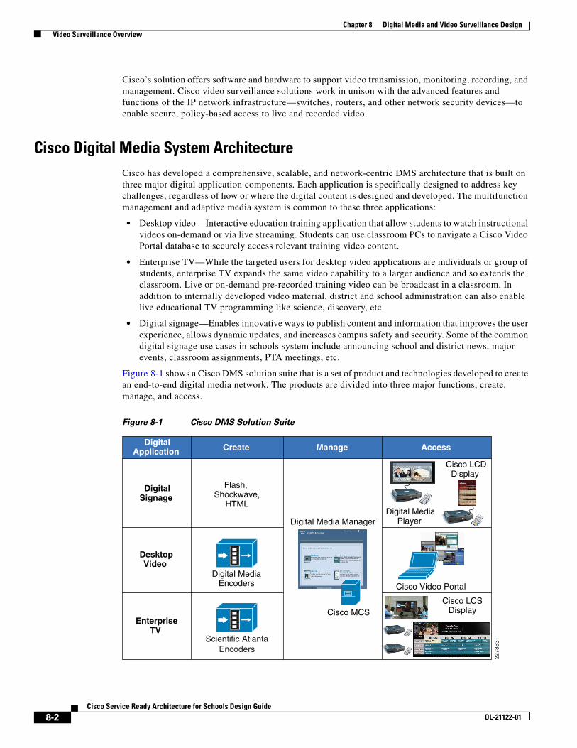
Figure 8-1 shows a Cisco DMS solution suite that is a set of product and technologies developed to create an end-to-end digital media network. The products are divided into three major functions, create, manage, and access.
Figure 8-1 Cisco DMS Solution Suite
Flash, Shockwave,
HTMLDigital Media
Player
Cisco Video Portal
Cisco LCSDisplay
Cisco LCDDisplay
Digital Media Manager
Cisco MCS
Digital MediaEncoders
Create Manage AccessDigitalApplication
DigitalSignage
DesktopVideo
EnterpriseTV
Scientific AtlantaEncoders
2278
53
8-2Cisco Service Ready Architecture for Schools Design Guide
OL-21122-01
Chapter 8 Digital Media and Video Surveillance Design Video Surveillance Overview
The digital media components in the Cisco DMS solution suite assist schools in deploying digital media solutions at their own pace; e.g., initially deploy digital signage with simple development applications and deploy interactive video solutions in subsequent phases.
The Cisco Digital Media Manager (DMM) is a Web-based application that simplifies deploying all three digital media applications in schools.
DMS Solution for SchoolsDMS solutions in schools have proven valuable in overcoming key challenges in the development of next-generation education delivery processes. DMS provides the flexibility to develop training content that can be accessed by students anytime, and anywhere. Cisco DMS relies on a resilient, scalable, and reliable network infrastructure for seamless end-to-end content delivery.
Figure 8-2 shows an end-to-end digital media reference model with all three applications enabling a unified digital network service for the school district.
The following are some of the key benefits of this DMS design model:
• Centralized management at the district office providing consistent publishing policies, security, scalability. and reduced operational and maintenance cost.
• Distributed storage and media access points enabling district office and schools to use centrally developed content with reduced bandwidth capacity and increased availability during network instability.
• In large-scale video networks, the Cisco Application and Content Network Services (ACNS) or WAN optimization appliances can be deployed to increase media performance and reduce expensive WAN bandwidth requirements.
8-3Cisco Service Ready Architecture for Schools Design Guide
OL-21122-01

Chapter 8 Digital Media and Video Surveillance Design Video Surveillance Overview
Figure 8-2 End-to-End Reference DMS Solution in School Network Architecture
The following section provides an overview of various deployment scenarios, device components, communication, and network requirements for digital media applications in schools. For a detailed digital media design and implementation guide, refer to:
http://www.cisco.com/en/US/docs/solutions/Enterprise/Video/DMS_DG/DMS_dg.html
Internet
WAN
Video
Admin
Regional School
Data Center Studio Classroom
HDTV
HDTV
HDTV HDTV
HDTV
HDTV
HDTV
Lobby Cafe
HDTV HDTV
Cafe
HDTV
StreamingServer
Web Server
Video
Scientific AtlanticEncoders
Digital Media Encoder
Digital SignageEnterprise TV
Desktop Videowith Video Portal
Digital MediaPlayer
School WebAdmin
Admin
District Office
Data Center Studio ConferenceRoom
HDTV HDTV HDTV
HDTV
HDTV
HDTV
Lobby Cafe
HDTV
StreamingServer
MXE
ADS/LDAP
DMM
DMSAdmin
CVP
Web Server
Scientific AtlanticEncoders
Digital MediaEncoder
2278
54
8-4Cisco Service Ready Architecture for Schools Design Guide
OL-21122-01
Chapter 8 Digital Media and Video Surveillance Design Desktop Video Application Overview
Desktop Video Application OverviewStudents, teachers, and administrative staff can watch live or pre-recorded video events from their personal computers at any location and at any time. The Cisco DMS Digital Video application empowers faculty to extend the classroom audience to remote locations by broadcasting live or recording training sessions available as video on-demand (VoD).
Cisco Desktop Video applications offer several benefits:
• Customizable interface with program guide and search window.
• Students can create a personalized video playlist.
• Questions and comments can be made during live video broadcast events.
• Restrict video content access based on Active Directory or LDAP authentication and privilege.
• Wide format support—Adobe Flash, Windows Media, H.264, QuickTime, etc.
• Player Controls—Synchronized slides, advanced video and controls, etc.
Desktop Video ComponentsAs one of the integrated components of the Cisco DMS solution suite, the digital video application uses common video development, management, and publishing components. In combination, external authentication servers can provide secure, on-demand video content and live video broadcast services to the desktop or on Cisco LCD TVs deployed in different physical locations.
The Cisco DMS solution suite consists of:
• Digital Media Manager (DMM)—Centralized management appliance in district office governs the content and communicates with local or remotely deployed critical desktop video components, e.g., CVP, HTTP server etc.
• Digital Media Encoder (DME)—Single or multi-channel media encoder receives live analog/digital feed from cameras or television service providers and transports over the IP network to the streaming server.
• Streaming Server—Provides stream splitting capabilities, allowing many clients to view a single live stream from DME or pre-recorded source (replay)
• Cisco Video Portal (CVP)—Web-based video navigation engine provides access to users after successful authentication with Active Directory or LDAP server.
• Web Server/Content Repository—Stores all VoDs referenced by Video Portal server. User triggers VoD request to access video content through CVP and the request gets redirected to pull video file from the content repository to the requested user.
Publishing Live and Video On-Demand ContentA critical feature of the Cisco Digital Media System for Cisco Desktop Video is its ability to simplify the publishing of live and on-demand digital media files to the Cisco Video Portal (CVP). On-demand video content can be uploaded from the developer’s computer directly to the DMM server for staging and previewing prior to deployment. This staging capability includes the addition of an approval process within the content workflow to help ensure that school branding, publishing policies, and messaging are properly incorporated in the content. Post approval process, the content can be moved or deployed to the Cisco Video Portal using secure file transmission.
8-5Cisco Service Ready Architecture for Schools Design Guide
OL-21122-01
Chapter 8 Digital Media and Video Surveillance Design Enterprise TV Application Overview
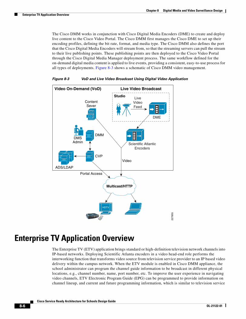
The Cisco DMM works in conjunction with Cisco Digital Media Encoders (DME) to create and deploy live content to the Cisco Video Portal. The Cisco DMM first manages the Cisco DME to set up their encoding profiles, defining the bit rate, format, and media type. The Cisco DMM also defines the port that the Cisco Digital Media Encoders will stream from, so that the streaming servers can pull the stream to their live publishing points. These publishing points are then deployed to the Cisco Video Portal through the Cisco Digital Media Manager deployment process. The same workflow defined for the on-demand digital media content is applied to live events, providing a consistent, easy-to-use process for all types of deployments. Figure 8-3 shows a schematic of Cisco DMM video management.
Figure 8-3 VoD and Live Video Broadcast Using Digital Video Application
Enterprise TV Application OverviewThe Enterprise TV (ETV) application brings standard or high-definition television network channels into IP-based networks. Deploying Scientific Atlanta encoders in a video head-end role performs the interworking function that transforms video source from television service provider to an IP based video delivery within the campus network. When the ETV module is enabled in Cisco DMM appliance, the school administrator can program the channel guide information to be broadcast in different physical locations, e.g., channel number, name, port number, etc. To improve the user experience in navigating video channels, ETV Electronic Program Guide (EPG) can be programmed to provide information on channel lineup, and current and future programming information, which is similar to television service
HDTV
Multicast/HTTP
Scientific AtlanticEncoders
Studio
DME
LiveVideoFeed
Video On-Demand (VoD) Live Video Broadcast
ADS/LDAP
DMM
ContentSever
DMSAdmin
CVPVideo
Portal Access22
7855
8-6Cisco Service Ready Architecture for Schools Design Guide
OL-21122-01

Chapter 8 Digital Media and Video Surveillance Design Enterprise TV Application Overview
provided programming guide. To watch the live video channels, users can use Cisco DMP and remote control to navigate and access the channel. Video delivery over IP networks can be unicast or multicast, depending on how IP/multicast is designed in campus network.
With larger displays in key physical locations, the ETV application becomes the primary communications interface in the district targeting large audiences. For example, live or VoD broadcast for education training, demonstrations, meetings, etc., targeting all the students in a classroom, or live news, etc.
Enterprise TV ComponentsTo broadcast school developed VoD or live video through ETV, the core Cisco DMS components used in the desktop video application can be leveraged to integrate ETV in the network. The primary difference between ETV and desktop video in this case would be Digital Media Player (DMP) instead of a PC as an access end point for a large screen display targeting a larger audience. To broadcast television network channels in the campus network, the Scientific Atlanta encoder must be integrated along with other ETV components. It is recommended to deploy distributed television service in local campus and not forward non-critical video traffic over the WAN infrastructure.
• Scientific Atlanta Encoder—An encoder system that provides interworking function between analog or digital television service provider and IP network. Encodes live video input and transforms into MPEG-2 or MPEG-4 multicast stream.
• Cisco Digital Media Player (DMP)—Key media access end point that connects to Cisco LCD TV for large size displays. DMP provides capabilities to decode multi-format graphics and stream video content received over unicast or multicast IP network.
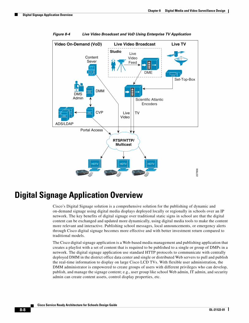
Broadcasting Live TV or Video On-Demand ContentThe communication flow between the DMP and the DMM and Video Portal function is similar to desktop video applications. Proper planning, technologies, and equipment must be deployed in campus network for successful live television video delivery. When designing the playlist in Cisco Enterprise TV module, the school administrator must understand that it can support up to 99 live and on-demand video channels broadcast in the campus network. The DMM administrator in the district office can use the DMM-ETV software module to create customized TV navigation interfaces, such as adding school logo and skins, programming video channel assignments, and configuring specific video channel assignment to DMP deployed in specific campus location. Figure 8-4 shows a schematic of the Enterprise TV video architecture.
District and school architects must understand the codec type required for publishing video in the campus network. Deployed digital encoders must follow the MPEG2 standard specification to stream the video. It is recommended to deploy Scientific Atlanta 9032SD or 9050HD encoder to stream live video stream to DMP for Enterprise TV application.
8-7Cisco Service Ready Architecture for Schools Design Guide
OL-21122-01
Chapter 8 Digital Media and Video Surveillance Design Digital Signage Application Overview
Figure 8-4 Live Video Broadcast and VoD Using Enterprise TV Application
Digital Signage Application OverviewCisco’s Digital Signage solution is a comprehensive solution for the publishing of dynamic and on-demand signage using digital media displays deployed locally or regionally in schools over an IP network. The key benefits of digital signage over traditional static signs in school are that the digital content can be exchanged and updated more dynamically, using digital media tools to make the content more relevant and interactive. Publishing school messages, local announcements, or emergency alerts through Cisco digital signage becomes more effective and with better investment return compared to traditional models.
The Cisco digital signage application is a Web-based media management and publishing application that creates a playlist with a set of content that is required to be published to a single or group of DMPs in a network. The digital signage application use standard HTTP protocols to communicate with centrally deployed DMM in the district office data center and single or distributed Web servers to pull and publish the real-time information to display on large Cisco LCD TVs. With flexible user administration, the DMM administrator is empowered to create groups of users with different privileges who can develop, publish, and manage the signage content; e.g., user group like school Web admin, IT admin, and security admin can create content assets, control display properties, etc.
HDTV HDTVHDTV
RTSP/HTTP/Multicast
Scientific AtlanticEncoders
Set-Top-Box
Studio
DME
LiveVideoFeed
Video On-Demand (VoD) Live Video Broadcast Live TV
ADS/LDAP
DMM
ContentSever
DMSAdmin
CVP LiveVideo
TV
Portal Access
2278
56
8-8Cisco Service Ready Architecture for Schools Design Guide
OL-21122-01
Chapter 8 Digital Media and Video Surveillance Design Digital Signage Application Overview
Digital Signage ComponentsThe requirements of the integrated digital media components depend on which content needs to be published through a signage module. The Cisco digital signage application provides the flexibility for the DMM administrator or school Web administrator to develop multi-functional, integrated content that can play key messages, stream VoD files from a content server, and keep connected with external information. For example, schools can publish a single Adobe flash file that is composed of static text information, embedded with education short VoD stream and live news information with RSS feed. The basic digital signage components are:
• Digital Media Manager (DMM)—Centralized management appliance in district office governs the content and communicate with local or remotely deployed critical desktop video components, e.g., CVP, HTTP server, etc.
• Cisco Digital Media Player (DMP)—The Cisco DMP is a highly reliable IP-based hardware endpoint for video decoding and playback of digital media content—including high-definition live broadcasts and VoD, Flash animations, text tickers, and other Web content—across digital displays. DMP is a critical component of the digital signage and ETV applications allow for the networking of digital displays and the broadcasting of live and on-demand media. The current DMP portfolio includes the Cisco DMP 4305G for standard signage and ETV and the Cisco DMP 4400G for high-end signage and ETV.
• Cisco LCD Professional Series—For an end-to-end Cisco digital media solution, the Cisco LCD professional series displays is a high definition LCD display that can be centrally managed through DMM.
• Web Server/Content Repository—Stores all HTML, VoDs, flash files referenced by HTTP server or Video Portal server. Multiple files can be played on same DMP; based on Web application design, the program triggers the content request and it is pulled by DMP from a source server.
Video Surveillance System ArchitectureThe Cisco Video Surveillance solution relies on an IP network infrastructure to link all components. The design of a highly available hierarchical network has been proven and tested for many years and allows applications to converge on an intelligent and resilient infrastructure.
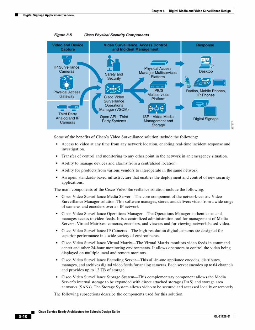
Figure 8-5 shows the main components of the Cisco Physical Security solution, including video surveillance, physical access control, incident response and integration with third-party systems.
8-9Cisco Service Ready Architecture for Schools Design Guide
OL-21122-01
Chapter 8 Digital Media and Video Surveillance Design Digital Signage Application Overview
Figure 8-5 Cisco Physical Security Components
Some of the benefits of Cisco’s Video Surveillance solution include the following:
• Access to video at any time from any network location, enabling real-time incident response and investigation.
• Transfer of control and monitoring to any other point in the network in an emergency situation.
• Ability to manage devices and alarms from a centralized location.
• Ability for products from various vendors to interoperate in the same network.
• An open, standards-based infrastructure that enables the deployment and control of new security applications.
The main components of the Cisco Video Surveillance solution include the following:
• Cisco Video Surveillance Media Server—The core component of the network-centric Video Surveillance Manager solution. This software manages, stores, and delivers video from a wide range of cameras and encoders over an IP network
• Cisco Video Surveillance Operations Manager—The Operations Manager authenticates and manages access to video feeds. It is a centralized administration tool for management of Media Servers, Virtual Matrixes, cameras, encoders, and viewers and for viewing network-based video.
• Cisco Video Surveillance IP Cameras—The high-resolution digital cameras are designed for superior performance in a wide variety of environments.
• Cisco Video Surveillance Virtual Matrix—The Virtual Matrix monitors video feeds in command center and other 24-hour monitoring environments. It allows operators to control the video being displayed on multiple local and remote monitors.
• Cisco Video Surveillance Encoding Server—This all-in-one appliance encodes, distributes, manages, and archives digital video feeds for analog cameras. Each server encodes up to 64 channels and provides up to 12 TB of storage.
• Cisco Video Surveillance Storage System—This complementary component allows the Media Server’s internal storage to be expanded with direct attached storage (DAS) and storage area networks (SANs). The Storage System allows video to be secured and accessed locally or remotely.
The following subsections describe the components used for this solution.
Video and DeviceCapture
Video Surveillance, Access Controland Incident Management
Response
2276
77
IP SurveillanceCameras
Radios, Mobile Phones,IP Phones
Digital Signage
Desktop
Cisco VideoSurveillanceOperations
Manager (VSOM)
Safety andSecurity
Third PartyAnalog and IP
Cameras
IP
Physical AccessManager Multiservices
Platform
Physical AccessGateway
IP
IPICSMultiservices
Platform
ISR - Video MediaManagement and
Storage
Open API - ThirdParty Systems
IP
8-10Cisco Service Ready Architecture for Schools Design Guide
OL-21122-01
Chapter 8 Digital Media and Video Surveillance Design Digital Signage Application Overview
Cisco Video Surveillance Media Server
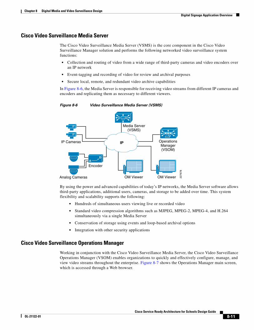
The Cisco Video Surveillance Media Server (VSMS) is the core component in the Cisco Video Surveillance Manager solution and performs the following networked video surveillance system functions:
• Collection and routing of video from a wide range of third-party cameras and video encoders over an IP network
• Event-tagging and recording of video for review and archival purposes
• Secure local, remote, and redundant video archive capabilities
In Figure 8-6, the Media Server is responsible for receiving video streams from different IP cameras and encoders and replicating them as necessary to different viewers.
Figure 8-6 Video Surveillance Media Server (VSMS)
By using the power and advanced capabilities of today’s IP networks, the Media Server software allows third-party applications, additional users, cameras, and storage to be added over time. This system flexibility and scalability supports the following:
• Hundreds of simultaneous users viewing live or recorded video
• Standard video compression algorithms such as MJPEG, MPEG-2, MPEG-4, and H.264 simultaneously via a single Media Server
• Conservation of storage using events and loop-based archival options
• Integration with other security applications
Cisco Video Surveillance Operations Manager
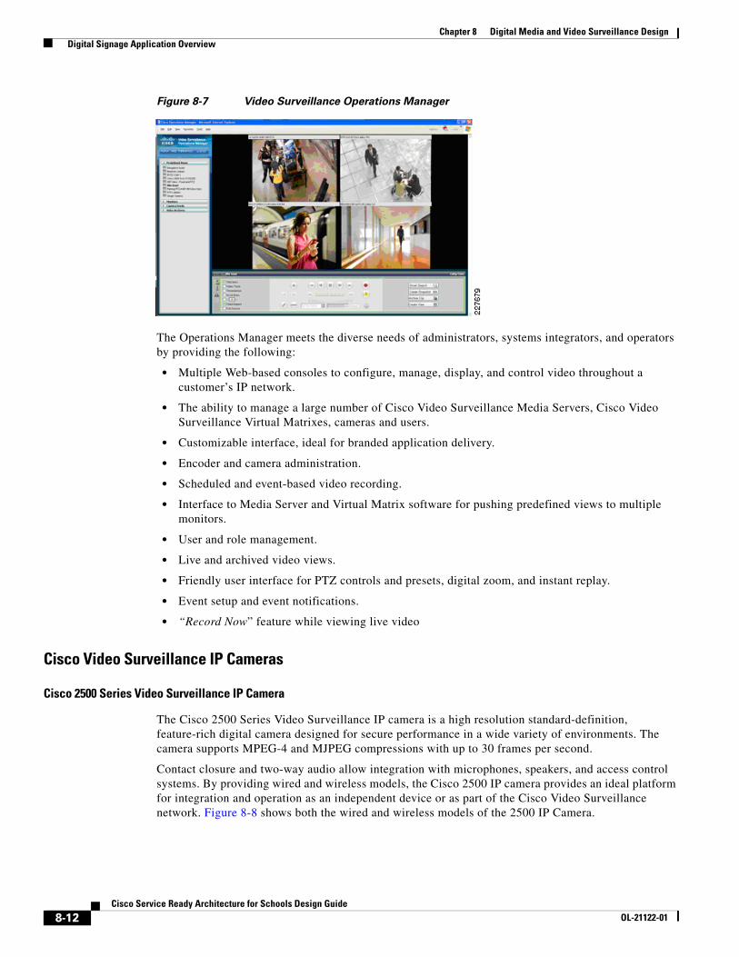
Working in conjunction with the Cisco Video Surveillance Media Server, the Cisco Video Surveillance Operations Manager (VSOM) enables organizations to quickly and effectively configure, manage, and view video streams throughout the enterprise. Figure 8-7 shows the Operations Manager main screen, which is accessed through a Web browser.
IP Cameras
Encoder
OM Viewer OM Viewer 2276
78
Media Server(VSMS)
OperationsManager(VSOM)
Analog Cameras
AD
IP
IP
IP
8-11Cisco Service Ready Architecture for Schools Design Guide
OL-21122-01
Chapter 8 Digital Media and Video Surveillance Design Digital Signage Application Overview
Figure 8-7 Video Surveillance Operations Manager
The Operations Manager meets the diverse needs of administrators, systems integrators, and operators by providing the following:
• Multiple Web-based consoles to configure, manage, display, and control video throughout a customer’s IP network.
• The ability to manage a large number of Cisco Video Surveillance Media Servers, Cisco Video Surveillance Virtual Matrixes, cameras and users.
• Customizable interface, ideal for branded application delivery.
• Encoder and camera administration.
• Scheduled and event-based video recording.
• Interface to Media Server and Virtual Matrix software for pushing predefined views to multiple monitors.
• User and role management.
• Live and archived video views.
• Friendly user interface for PTZ controls and presets, digital zoom, and instant replay.
• Event setup and event notifications.
• “Record Now” feature while viewing live video
Cisco Video Surveillance IP Cameras
Cisco 2500 Series Video Surveillance IP Camera
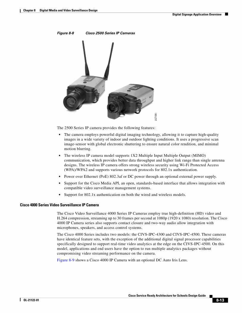
The Cisco 2500 Series Video Surveillance IP camera is a high resolution standard-definition, feature-rich digital camera designed for secure performance in a wide variety of environments. The camera supports MPEG-4 and MJPEG compressions with up to 30 frames per second.
Contact closure and two-way audio allow integration with microphones, speakers, and access control systems. By providing wired and wireless models, the Cisco 2500 IP camera provides an ideal platform for integration and operation as an independent device or as part of the Cisco Video Surveillance network. Figure 8-8 shows both the wired and wireless models of the 2500 IP Camera.
8-12Cisco Service Ready Architecture for Schools Design Guide
OL-21122-01
Chapter 8 Digital Media and Video Surveillance Design Digital Signage Application Overview
Figure 8-8 Cisco 2500 Series IP Cameras
The 2500 Series IP camera provides the following features:
• The camera employs powerful digital imaging technology, allowing it to capture high-quality images in a wide variety of indoor and outdoor lighting conditions. It uses a progressive scan image-sensor with global electronic shuttering to ensure natural color rendition, and minimal motion blurring.
• The wireless IP camera model supports 1X2 Multiple Input Multiple Output (MIMO) communication, which provides better data throughput and higher link range than single antenna designs. The wireless IP camera offers strong wireless security using Wi-Fi Protected Access (WPA)/WPA2 and supports various network protocols for 802.1x authentication.
• Power over Ethernet (PoE) 802.3af or DC power through an optional external power supply.
• Support for the Cisco Media API, an open, standards-based interface that allows integration with compatible video surveillance management systems.
• Support for 802.1x authentication on both the wired and wireless models.
Cisco 4000 Series Video Surveillance IP Camera
The Cisco Video Surveillance 4000 Series IP Cameras employ true high-definition (HD) video and H.264 compression, streaming up to 30 frames per second at 1080p (1920 x 1080) resolution. The Cisco 4000 IP Camera series also supports contact closure and two-way audio allow integration with microphones, speakers, and access control systems.
The Cisco 4000 Series includes two models: the CIVS-IPC-4300 and CIVS-IPC-4500. These cameras have identical feature sets, with the exception of the additional digital signal processor capabilities specifically designed to support real-time video analytics at the edge on the CIVS-IPC-4500. On this model, applications and end users have the option to run multiple analytics packages without compromising video streaming performance on the camera.
Figure 8-9 shows a Cisco 4000 IP Camera with an optional DC Auto Iris Lens.
8-13Cisco Service Ready Architecture for Schools Design Guide
OL-21122-01

Chapter 8 Digital Media and Video Surveillance Design Digital Signage Application Overview
Figure 8-9 Cisco 4000 Series IP Camera
The 4000 Series IP camera provides the following features:
• True high-definition video—The camera streams crisp and clear 1080p (1920 x 1080) video at 30 frames per second while maintaining surprisingly low network bandwidth.
• Progressive scan video—The camera captures each frame at its entire resolution using progressive scan rather than interlaced video capture, which captures each field of video.
• Embedded security and networking—The camera provides hardware-based Advanced Encryption Standard (AES).
• IP Multicast for enhanced bandwidth management.
• Event notification—The camera can examine designated areas for activity and notify users or other applications when it detects activity that exceeds a predefined sensitivity and threshold.
• True day/night functionality that includes an infrared (IR) filter that automatically switches to night mode in low light scenes.
• The camera supports Power-over-Ethernet (PoE) 802.3af, 12 VDC or 24 VAC power through an optional external power supply.
• The camera can be installed with a fixed mount or with an optional external pan/tilt mount and motorized zoom lens.
For more information, see the Physical Safety for Schools Application Deployment Guide:http://www.cisco.com/en/US/docs/solutions/Verticals/Education/safe_sec_ed_dg.html
Deploying Digital Signage in School CampusTo ensure a successful digital media deployment, network, display, and management planning must be done prior to deploying digital signage in the schools network. A well-planned digital signage network design provides flexibility to incrementally deploy desktop video and ETV digital media applications without making major infrastructure changes. As described earlier, digital signage uses standard HTTP protocols to pull and publish the signage content on displays. Network bandwidth consumption for digital signs varies widely as it depends on playlist and content types. This document provides the best practices to design and configure the digital signage with content developed with rich text, flash, and animation and located on distributed Web servers to increase network efficiency.
Centralized Management Model
Cisco DMM is highly scalable appliance server that can be deployed centrally in district office location to manage up to 1000 DMPs deployed in local and regional school campus network. Cisco DMP deployed in local district offices or remote regional schools can communicate with centralized DMM
8-14Cisco Service Ready Architecture for Schools Design Guide
OL-21122-01
Chapter 8 Digital Media and Video Surveillance Design Digital Signage Application Overview
over LAN and WAN network using standard HTTP as the control protocol to receive Web or content server re-direction information to display content. Deploying DMM in a centralized location allows the DMM administrators in district offices to manage all registered DMP in various ways:
• Add and archive digital content and assign metadata and keywords.
• Create and manage play lists, ticker alerts, messages, closed captions, and promotional interstitials.
• Preview digital signage content and manage approval workflow.
• Ability to pre-configure the playlist and schedule for instant and future deployments.
• Take WAN optimization solution advantage and provide tight integration with Cisco ACNS and Cisco Content Engines.
• Manage user administrator accounts and permissions.
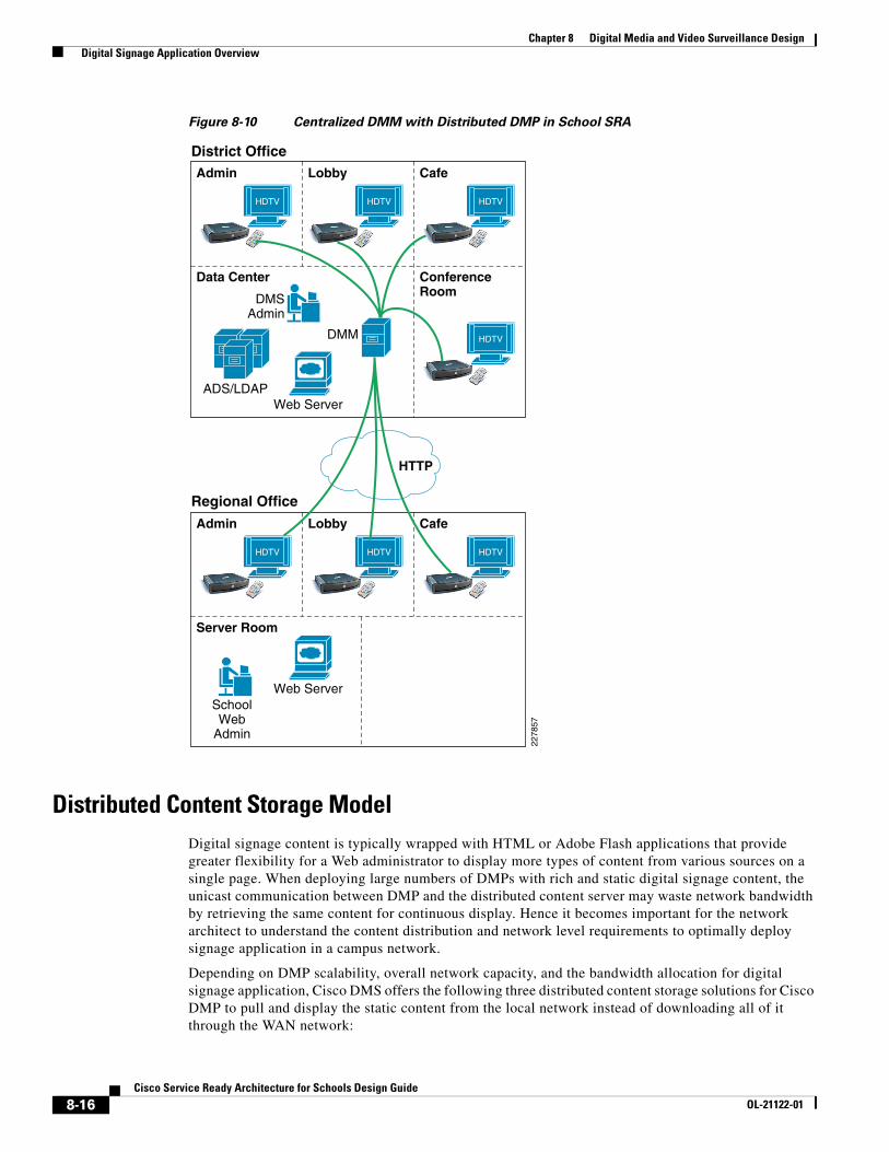
Centralizing DMP management and publishing signage content centrally at a district office allows the DMM administrator to advertise consistent information and messaging throughout the network. To minimize WAN network utilization, the school administrator must leverage internal storage or their local Web server to store and advertise the local, regional, and department news and information. However the district office and Internet news must be communicated over the WAN.
The network architect must consider integrating enterprise-class Cisco Application and Content Networking System (ACNS) that uses caching technology and offers higher scalability and reliable video delivery solution at the schools to improve end user experience and application response time. When integrated with the Cisco Wide-Area Application Services (WAAS) solution, it helps in optimizing WAN bandwidth utilization significantly with local redirection and high data compression over the WAN.
Figure 8-10 is a validated design to integrate digital signage with centralized management in the district office with distributed DMP in a large-scale school network.
8-15Cisco Service Ready Architecture for Schools Design Guide
OL-21122-01
Chapter 8 Digital Media and Video Surveillance Design Digital Signage Application Overview
Figure 8-10 Centralized DMM with Distributed DMP in School SRA
Distributed Content Storage ModelDigital signage content is typically wrapped with HTML or Adobe Flash applications that provide greater flexibility for a Web administrator to display more types of content from various sources on a single page. When deploying large numbers of DMPs with rich and static digital signage content, the unicast communication between DMP and the distributed content server may waste network bandwidth by retrieving the same content for continuous display. Hence it becomes important for the network architect to understand the content distribution and network level requirements to optimally deploy signage application in a campus network.
Depending on DMP scalability, overall network capacity, and the bandwidth allocation for digital signage application, Cisco DMS offers the following three distributed content storage solutions for Cisco DMP to pull and display the static content from the local network instead of downloading all of it through the WAN network:
HTTP
Web Server
Regional Office
District Office
HDTV
Admin
HDTV
Lobby
HDTV
Cafe
HDTV
ConferenceRoom
ADS/LDAP
Data Center
DMM
DMSAdmin
2278
57
Web Server
HDTV
Admin
HDTV
Lobby
HDTV
Cafe
Server Room
SchoolWeb
Admin
8-16Cisco Service Ready Architecture for Schools Design Guide
OL-21122-01
Chapter 8 Digital Media and Video Surveillance Design Digital Signage Application Overview
• Cisco DMS-Content Distribution (CD)—Is an ideal solution for a small-scale school network with few Cisco DMPs. Cisco DMM can push the static HTML or flash content via FTP or SFTP protocol to Cisco DMM on internal storage or to external storage device like USB drive and redirect Cisco DMP to access internal storage. This solution helps to minimize WAN bandwidth utilization.
• Local Content Server (Web or CIFS)—Storing the digital media content on a single local content server, like HTTP or CIFS sever, gives the network administrator more flexibility and management of the content distribution solution. The Web administrator can dynamically add, modify, and store the updated HTML or Flash file on a centralized server for Cisco DMP to retrieve and display. On the next HTTP request from DMP, the refreshed copy is displayed automatically. This solution provides more flexibility compared to Cisco DMS-CD solution, as it can dynamically update content without updating and managing content on each individual Cisco DMP.
• Cisco ACNS—Highly scalable and intelligent large size video content distribution to remote locations. Hierarchical content distribution system at district office and school sites distributes single copy of pre-recorded video to ACNS edge at the schools. To increase WAN network efficiency, Cisco ACNS leverages the caching technology and provides unicast VoD delivery in local LAN networks to end users instead of downloading one copy for each user over the WAN network.
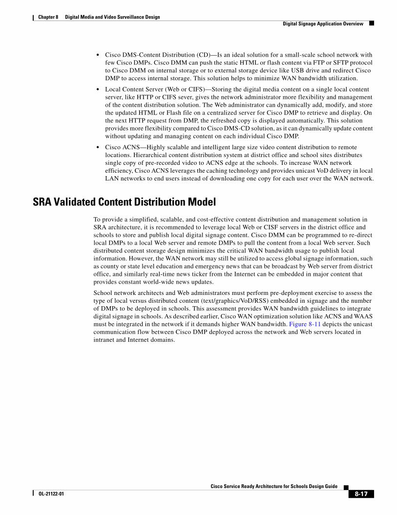
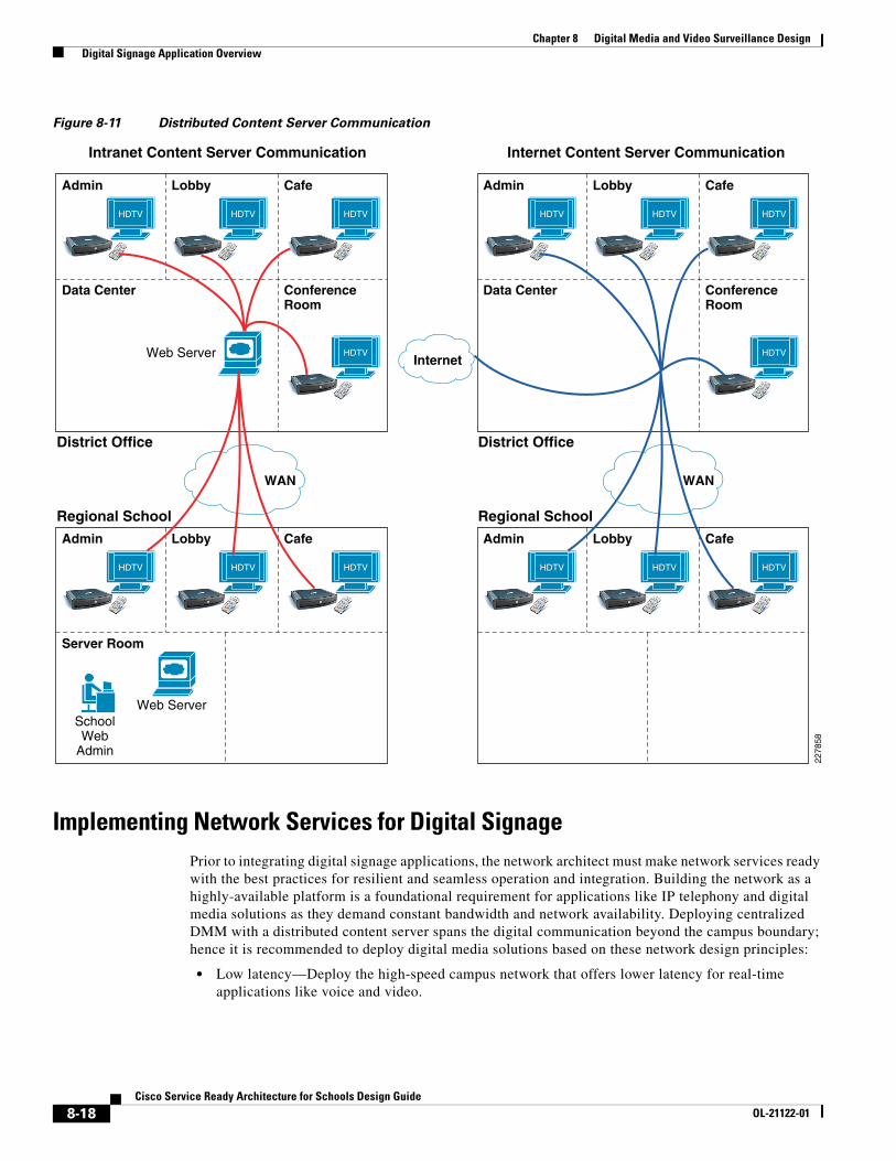
SRA Validated Content Distribution ModelTo provide a simplified, scalable, and cost-effective content distribution and management solution in SRA architecture, it is recommended to leverage local Web or CISF servers in the district office and schools to store and publish local digital signage content. Cisco DMM can be programmed to re-direct local DMPs to a local Web server and remote DMPs to pull the content from a local Web server. Such distributed content storage design minimizes the critical WAN bandwidth usage to publish local information. However, the WAN network may still be utilized to access global signage information, such as county or state level education and emergency news that can be broadcast by Web server from district office, and similarly real-time news ticker from the Internet can be embedded in major content that provides constant world-wide news updates.
School network architects and Web administrators must perform pre-deployment exercise to assess the type of local versus distributed content (text/graphics/VoD/RSS) embedded in signage and the number of DMPs to be deployed in schools. This assessment provides WAN bandwidth guidelines to integrate digital signage in schools. As described earlier, Cisco WAN optimization solution like ACNS and WAAS must be integrated in the network if it demands higher WAN bandwidth. Figure 8-11 depicts the unicast communication flow between Cisco DMP deployed across the network and Web servers located in intranet and Internet domains.
8-17Cisco Service Ready Architecture for Schools Design Guide
OL-21122-01
Chapter 8 Digital Media and Video Surveillance Design Digital Signage Application Overview
Figure 8-11 Distributed Content Server Communication
Implementing Network Services for Digital SignagePrior to integrating digital signage applications, the network architect must make network services ready with the best practices for resilient and seamless operation and integration. Building the network as a highly-available platform is a foundational requirement for applications like IP telephony and digital media solutions as they demand constant bandwidth and network availability. Deploying centralized DMM with a distributed content server spans the digital communication beyond the campus boundary; hence it is recommended to deploy digital media solutions based on these network design principles:
• Low latency—Deploy the high-speed campus network that offers lower latency for real-time applications like voice and video.
WAN
Regional School
District Office
HDTV
Admin
HDTV
Lobby
HDTV
Cafe
HDTV
ConferenceRoom
Data Center
2278
58
HDTV
Admin
HDTV
Lobby
HDTV
Cafe
WAN
Web Server
Regional School
District Office
Intranet Content Server Communication Internet Content Server Communication
HDTV
Admin
HDTV
Lobby
HDTV
Cafe
HDTV
ConferenceRoom
Data Center
Web Server
HDTV
Admin
HDTV
Lobby
HDTV
Cafe
Server Room
SchoolWeb
Admin
Internet
8-18Cisco Service Ready Architecture for Schools Design Guide
OL-21122-01
Chapter 8 Digital Media and Video Surveillance Design Digital Signage Application Overview
• High availability—To increase network resiliency it is recommended to deploy the network with redundant modules, systems, and power supplies offering non-stop communication and sub-second network recovery during minor or major network failure events.
• QoS—Enhance user experience and content quality with robust QoS policies at the campus network edge.
• Confidentiality—Protect digital media end points, appliances, and data with centralized authentication and encryption.
This section provides access ayer design and configuration guidelines to deploy Cisco DMP at the campus network edge and DMM in a centralized data center in a district office. For more information on design and implementation guideline for building a strong and resilient core and foundational campus network, refer to the following URL:
http://www.cisco.com/en/US/docs/solutions/Verticals/Education/SRA_Schools/school_sra_campus_dg.pdf
Deploying Cisco DMP in the Access Layer NetworkCisco DMP is a school managed and trusted end point in the campus access layer, hence the network administrator must apply the common security and QoS policy for DMP as defined for other trusted end-points like IP phones. In a typical deployment scenario, a single access layer switch may be connected to several other trusted and un-trusted end-points, hence it becomes an important task for administrator to provide secure and suitable network services.
Cisco access layer switches provides the flexibility to deploy Cisco DMP in two different modes, manual deployment and plug-and-play Auto Smartport (ASP) macro.
Manual Deployment
School administrator must manually implement the following three major network services to successfully integrate DMP in the network:
• Assigning unique Layer 2 VLAN
• Implement network edge security
• Implement network edge QoS
Assigning Unique Layer 2 VLAN
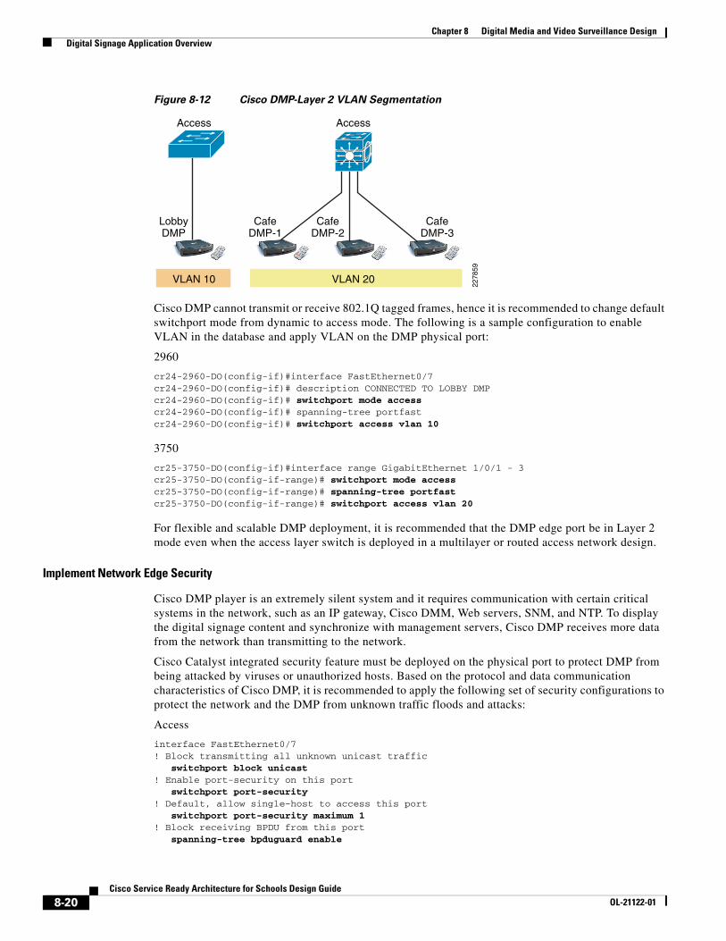
To provide secured and simplified digital signage communication, the DMP must be assigned a unique broadcast domain. De-coupling DMP with other trusted and un-trusted end points makes DMP more secure during any attacks and is easier to manage and troubleshoot. When single access layer connects to multiple DMPs, then all the DMPs can be assigned on the same Layer 2 VLAN. Like any other logical network partition design, it is recommended to use unique Layer 2 VLAN for DMP that are physically deployed on different Cisco access layer switches. Figure 8-12 provides recommended Cisco DMP Layer 2 segmentation guidelines in the access-layer:
8-19Cisco Service Ready Architecture for Schools Design Guide
OL-21122-01
Chapter 8 Digital Media and Video Surveillance Design Digital Signage Application Overview
Figure 8-12 Cisco DMP-Layer 2 VLAN Segmentation
Cisco DMP cannot transmit or receive 802.1Q tagged frames, hence it is recommended to change default switchport mode from dynamic to access mode. The following is a sample configuration to enable VLAN in the database and apply VLAN on the DMP physical port:
2960
cr24-2960-DO(config-if)#interface FastEthernet0/7cr24-2960-DO(config-if)# description CONNECTED TO LOBBY DMPcr24-2960-DO(config-if)# switchport mode accesscr24-2960-DO(config-if)# spanning-tree portfastcr24-2960-DO(config-if)# switchport access vlan 10
3750
cr25-3750-DO(config-if)#interface range GigabitEthernet 1/0/1 - 3cr25-3750-DO(config-if-range)# switchport mode accesscr25-3750-DO(config-if-range)# spanning-tree portfastcr25-3750-DO(config-if-range)# switchport access vlan 20
For flexible and scalable DMP deployment, it is recommended that the DMP edge port be in Layer 2 mode even when the access layer switch is deployed in a multilayer or routed access network design.
Implement Network Edge Security
Cisco DMP player is an extremely silent system and it requires communication with certain critical systems in the network, such as an IP gateway, Cisco DMM, Web servers, SNM, and NTP. To display the digital signage content and synchronize with management servers, Cisco DMP receives more data from the network than transmitting to the network.
Cisco Catalyst integrated security feature must be deployed on the physical port to protect DMP from being attacked by viruses or unauthorized hosts. Based on the protocol and data communication characteristics of Cisco DMP, it is recommended to apply the following set of security configurations to protect the network and the DMP from unknown traffic floods and attacks:
Access
interface FastEthernet0/7! Block transmitting all unknown unicast traffic switchport block unicast! Enable port-security on this port switchport port-security! Default, allow single-host to access this port switchport port-security maximum 1! Block receiving BPDU from this port spanning-tree bpduguard enable
Access
LobbyDMP
CafeDMP-1
CafeDMP-2
CafeDMP-3
2278
59
Access
VLAN 10 VLAN 20
8-20Cisco Service Ready Architecture for Schools Design Guide
OL-21122-01
Chapter 8 Digital Media and Video Surveillance Design Digital Signage Application Overview
Implement Network Edge QoS
It is important to implement differential service treatment for digital media applications over non-critical network traffic in the network. Depending on the digital media applications and the distributed content, appropriate QoS services must be implemented at the network edge that connects media end-points and in the data center where typically centralized management and content servers are deployed. As described earlier, the Cisco DMP primarily use standard HTTP protocol to communicate with centralized DMM management server and the distributed Web server to publish the digital signage content.
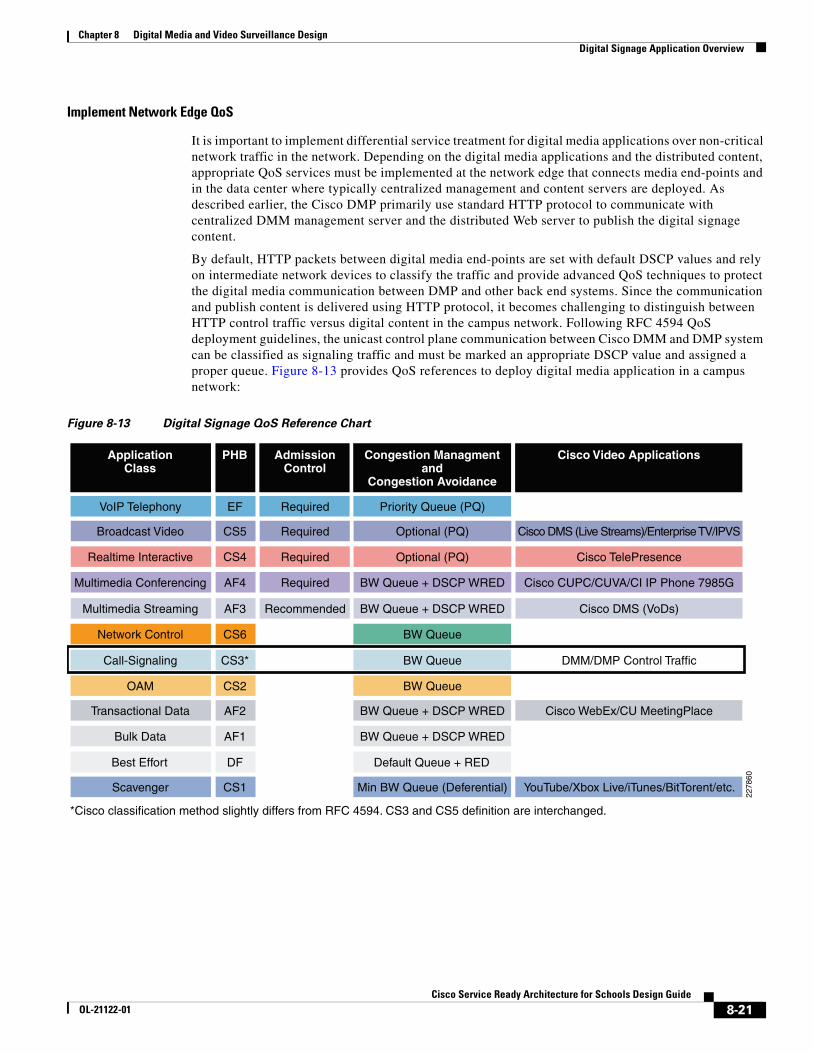
By default, HTTP packets between digital media end-points are set with default DSCP values and rely on intermediate network devices to classify the traffic and provide advanced QoS techniques to protect the digital media communication between DMP and other back end systems. Since the communication and publish content is delivered using HTTP protocol, it becomes challenging to distinguish between HTTP control traffic versus digital content in the campus network. Following RFC 4594 QoS deployment guidelines, the unicast control plane communication between Cisco DMM and DMP system can be classified as signaling traffic and must be marked an appropriate DSCP value and assigned a proper queue. Figure 8-13 provides QoS references to deploy digital media application in a campus network:
Figure 8-13 Digital Signage QoS Reference Chart
OAM
Network Control
Broadcast Video
ApplicationClass
Call-Signaling CS3*
*Cisco classification method slightly differs from RFC 4594. CS3 and CS5 definition are interchanged.
Realtime Interactive
CS5
CS2
Transactional Data AF2
Bulk Data AF1
Best Effort DF
Best Effort DFScavenger CS1
Best Effort DF
VoIP Telephony
Multimedia Streaming AF3 Recommended
Multimedia Conferencing AF4 Required
Required
AdmissionControl
Required
Required
BW Queue
BW Queue
BW Queue + DSCP WRED
BW Queue + DSCP WRED
Optional (PQ)
Congestion Managmentand
Congestion Avoidance
BW Queue
Optional (PQ)
BW Queue + DSCP WRED
BW Queue + DSCP WRED
Best Effort
Best EffortMin BW Queue (Deferential)
Default Queue + RED
Priority Queue (PQ)
Cisco DMS (VoDs)
Cisco CUPC/CUVA/CI IP Phone 7985G
Cisco DMS (Live Streams)/Enterprise TV/IPVS
Cisco Video Applications
DMM/DMP Control Traffic
Cisco TelePresence
Cisco WebEx/CU MeetingPlace
Best EffortYouTube/Xbox Live/iTunes/BitTorent/etc.
PHB
EF
CS6
2278
60
CS4
8-21Cisco Service Ready Architecture for Schools Design Guide
OL-21122-01
Chapter 8 Digital Media and Video Surveillance Design Digital Signage Application Overview
Applying Ingress QoS Policy on DMP and DMM Port
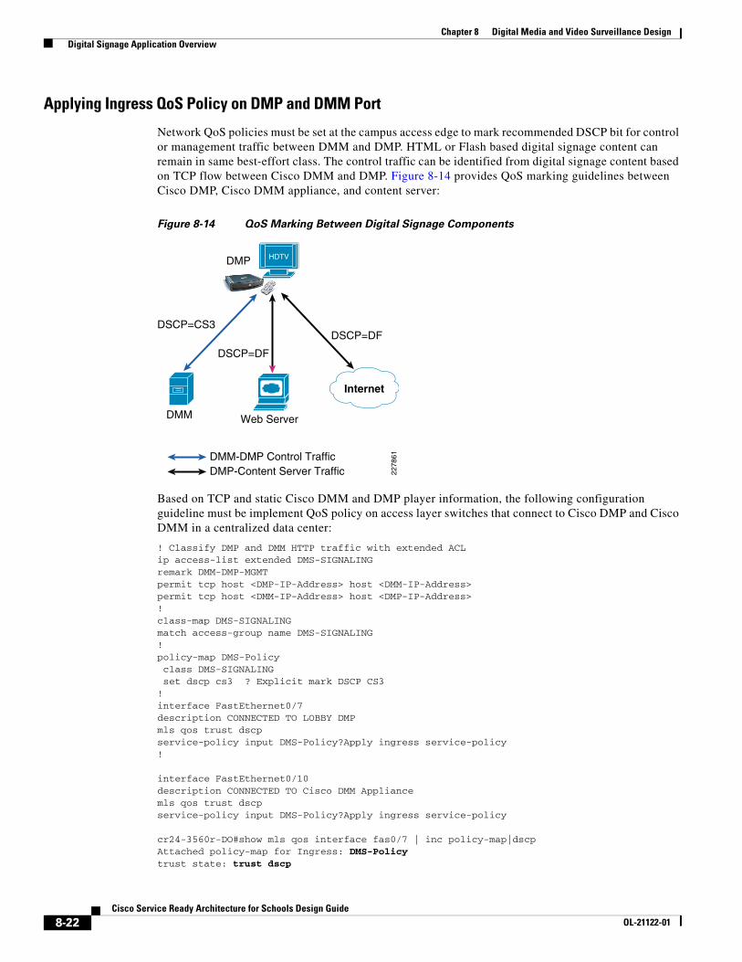
Network QoS policies must be set at the campus access edge to mark recommended DSCP bit for control or management traffic between DMM and DMP. HTML or Flash based digital signage content can remain in same best-effort class. The control traffic can be identified from digital signage content based on TCP flow between Cisco DMM and DMP. Figure 8-14 provides QoS marking guidelines between Cisco DMP, Cisco DMM appliance, and content server:
Figure 8-14 QoS Marking Between Digital Signage Components
Based on TCP and static Cisco DMM and DMP player information, the following configuration guideline must be implement QoS policy on access layer switches that connect to Cisco DMP and Cisco DMM in a centralized data center:
! Classify DMP and DMM HTTP traffic with extended ACL ip access-list extended DMS-SIGNALINGremark DMM-DMP-MGMTpermit tcp host <DMP-IP-Address> host <DMM-IP-Address>permit tcp host <DMM-IP-Address> host <DMP-IP-Address> !class-map DMS-SIGNALINGmatch access-group name DMS-SIGNALING!policy-map DMS-Policy class DMS-SIGNALING set dscp cs3 ? Explicit mark DSCP CS3!interface FastEthernet0/7description CONNECTED TO LOBBY DMPmls qos trust dscpservice-policy input DMS-Policy?Apply ingress service-policy!
interface FastEthernet0/10description CONNECTED TO Cisco DMM Appliancemls qos trust dscpservice-policy input DMS-Policy?Apply ingress service-policy
cr24-3560r-DO#show mls qos interface fas0/7 | inc policy-map|dscpAttached policy-map for Ingress: DMS-Policytrust state: trust dscp
HDTVDMP
DSCP=DF
DMM-DMP Control TrafficDMP-Content Server Traffic
DSCP=DFDSCP=CS3
DMM
2278
61Internet
Web Server
8-22Cisco Service Ready Architecture for Schools Design Guide
OL-21122-01
Chapter 8 Digital Media and Video Surveillance Design Digital Signage Application Overview
trust mode: trust dscp
Additional ingress QoS policies, such as policers, can be implemented on access switches if the network administrator is concerned about securing the restricting ports to consume higher bandwidth.
Applying Egress QoS Policy on DMP and DMM Port
Ingress QoS policy helps the network to distinguish between HTTP control and digital media content traffic within the campus backbone. Similar QoS techniques are required to provide differential services between control and digital media content traffic exiting the port connected to Cisco DMP and DMM appliance on the access layer switches. For global egress policy for trusted and un-trusted device, it is recommended to share the egress bandwidth to each hardware queue and enable prioritization for the low-latency traffic:
cr24-3560r-DO(config)#interface FastEthernet0/7cr24-3560r-DO(config-if)# srr-queue bandwidth share 1 30 35 5 ? Enable BW sharecr24-3560r-DO(config)#priority-queue out? Enable Priority-Queueing
cr24-3560r-DO#show mls qos interface fast0/7 queueingFastEthernet0/7Egress Priority Queue : enabledShaped queue weights (absolute) : 25 0 0 0Shared queue weights : 1 30 35 5The port bandwidth limit : 100 (Operational Bandwidth:100.0)The port is mapped to qset : 1
To deploy QoS in a school campus network design, refer to the following URL:
http://www.cisco.com/en/US/docs/solutions/Verticals/Education/SRA_Schools/SchoolSRA_QoS_sba.pdf
Auto Smartport Macro Deployment
Cisco access layer switches provide a zero-touch or plug-n-play type network provisioning solution by dynamically detecting connected end-points and automatically applying best practices and recommended configurations. Cisco Auto Smartport macro helps network architects to reduce the number of challenges in implementation when deploying complex configurations. Cisco validated design comprehensively validates multiple set of tools and technologies to solve the critical business problems. Cisco Auto Smartport leverages validated and recommended network configuration and parameters that dynamically provision the network without any user intervention. Implementing recommended and validated configuration parameters helps school network administrators to automatically provide network and device security and optimize application performance.
Cisco Auto Smartport leverages several Layer 2 protocol techniques to dynamically detect the end-point platform that intelligently triggers the function and applies the configuration from pre-defined recommended templates. To further increase operational efficiency, Cisco Auto Smartport removes all dynamically applied configurations when the device is un-plugged or removed from the network. The following is the list of Layer 2 technologies and end-point types that Cisco Auto Smartport macros use to dynamically apply configurations:
• Layer 2 Technologies
– Cisco Discovery Protocol (CDP)
– IEEE AB - LLDP
– 802.1x
– MAC-Authentication Bypass (MAB)
8-23Cisco Service Ready Architecture for Schools Design Guide
OL-21122-01
Chapter 8 Digital Media and Video Surveillance Design Digital Signage Application Overview
– Layer 2 Source MAC address
– Ethernet OUI
• Supported End-Point Platforms
– IP Phones—Cisco and Avaya IP Phone
– Wireless Access-Points—Cisco AP 11xx series
– IP Video Surveillance—Cisco IPVS 25xx and 4xxx series camera
– Digital Media Player—Cisco DMP 4x00 series players
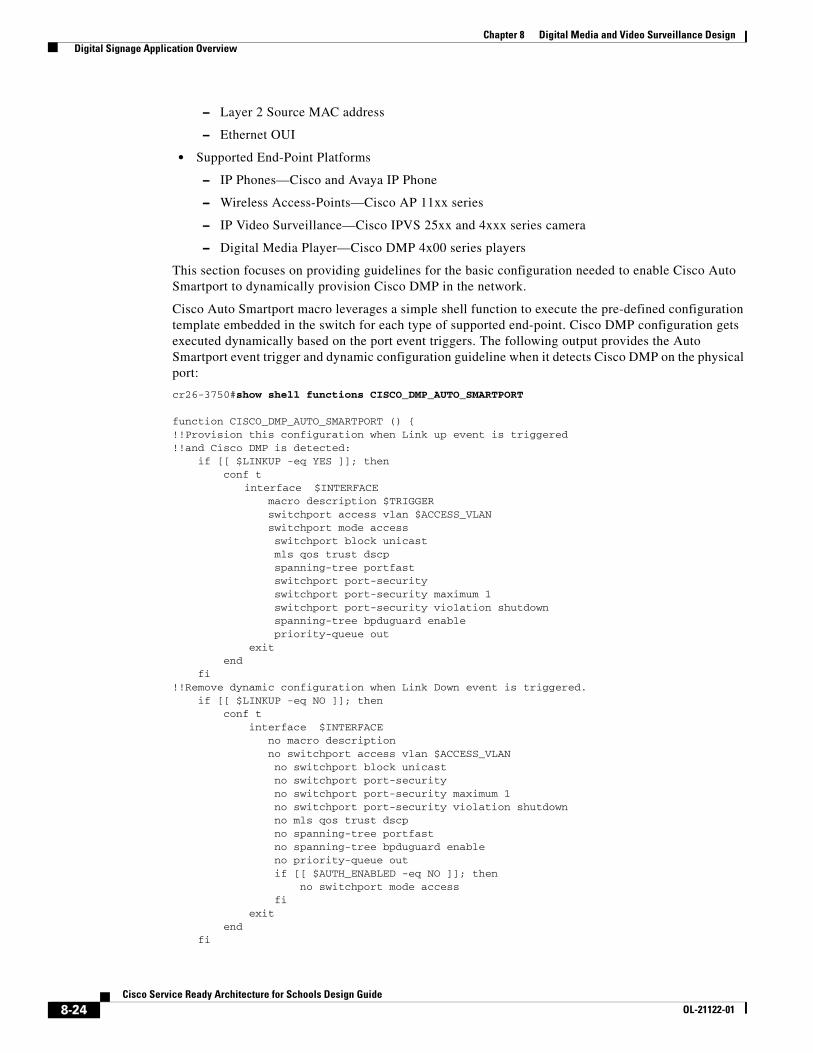
This section focuses on providing guidelines for the basic configuration needed to enable Cisco Auto Smartport to dynamically provision Cisco DMP in the network.
Cisco Auto Smartport macro leverages a simple shell function to execute the pre-defined configuration template embedded in the switch for each type of supported end-point. Cisco DMP configuration gets executed dynamically based on the port event triggers. The following output provides the Auto Smartport event trigger and dynamic configuration guideline when it detects Cisco DMP on the physical port:
cr26-3750#show shell functions CISCO_DMP_AUTO_SMARTPORT
function CISCO_DMP_AUTO_SMARTPORT () {!!Provision this configuration when Link up event is triggered!!and Cisco DMP is detected: if [[ $LINKUP -eq YES ]]; then conf t
interface $INTERFACEmacro description $TRIGGERswitchport access vlan $ACCESS_VLAN
switchport mode access switchport block unicast mls qos trust dscp spanning-tree portfast switchport port-security switchport port-security maximum 1 switchport port-security violation shutdown spanning-tree bpduguard enable priority-queue out exit end fi!!Remove dynamic configuration when Link Down event is triggered. if [[ $LINKUP -eq NO ]]; then conf t interface $INTERFACE
no macro description no switchport access vlan $ACCESS_VLAN no switchport block unicast no switchport port-security no switchport port-security maximum 1 no switchport port-security violation shutdown no mls qos trust dscp no spanning-tree portfast no spanning-tree bpduguard enable no priority-queue out if [[ $AUTH_ENABLED -eq NO ]]; then no switchport mode access fi exit end fi
8-24Cisco Service Ready Architecture for Schools Design Guide
OL-21122-01

Chapter 8 Digital Media and Video Surveillance Design Digital Signage Application Overview
}
Comparing the Auto Smartport macro configuration with a recommended manual configuration, it can be seen that the majority of the recommended manual configuration is in the macro template. Some of the advanced QoS parameters, such as MQC-based DSCP marking, may have to be manually configured.
Implementing Auto SmartPort Macro
School network administrators must enable Cisco Auto SmartPort Macro function along with basic network parameters on access layer switches to dynamically detect and provision the configuration for various types of end-points. Enabling Cisco Auto Smartport macro function globally enables all the physical ports and provisions and un-provisions the network configuration for the Cisco DMP based on shell triggers and functions. It also provides the flexibility to disable the Auto Smartport function on a per-port basis where the static configuration is required. The following is the simple global configuration to enable Cisco Auto Smartport processing for all the physical ports:
3750
cr26-3750(config)#macro auto global processing
cr26-3750#show macro auto interface | inc Auto Global Auto Smart Port Status Auto Smart Ports Enabled
As described earlier, Cisco Auto Smartport can leverage multiple Layer 2 technologies to detect the end-points, by default Auto SmartPort use the pre-defined MAC address-group range to dynamically detect the Cisco DMP based on Ethernet OUI address. To deploy Cisco DMP based on Ethernet OUI, no additional configuration is required. To enable secure access-control solution, Cisco Secure ACS and MAB can be integrated to authenticate Cisco DMP based on registered MAC address in the ACS database.
cr26-3750#show macro auto address-group CISCO_DMP_EVENTMAC Address Group Configuration:Group Name OUI MAC ADDRESS --------------------------------------------------------------------------CISCO_DMP_EVENT 0023.AC
000F.44
Because some of the network parameters like VLAN IDs are unique in the network, the school administrator needs to determine the common VLAN ID to deploy for a common set of end points. For example, when Cisco DMP is detected on Switch1, then it must dynamically detect the media player and assign it to appropriate VLAN and execute the network configuration template. By default, when Cisco Auto Smartport detects the Cisco DMP device on the port it configures the port in access-mode and assigned it a default VLAN ID = 1. After applying following single global configuration, the Auto Smartport automatically assigns all the Cisco DMP in to user-defined VLAN.
cr26-3750(config)#macro auto device media-player ACCESS_VLAN=58
cr26-3750#show macro auto device media-player | inc Device|ACCESSDevice:media-playerConfigurable Parameters:ACCESS_VLANDefaults Parameters:ACCESS_VLAN=1Current Parameters:ACCESS_VLAN=58
Tuning Auto SmartPort Macro
Cisco Auto Smartport is optimized in detecting the end points and provisioning the configuration for rapid and error-free deployments. The shell function that performs the configuration provisioning and un-provisioning task is based on physical link up and down events. In initial deployment, the end-points
8-25Cisco Service Ready Architecture for Schools Design Guide
OL-21122-01
Chapter 8 Digital Media and Video Surveillance Design Digital Signage Application Overview
can be detected using different Layer 2 techniques and all dynamically provisioned configurations can be saved in configuration files. Due to its nature the configuration is removed and then the same configuration is re-applied when the link goes down temporarily for any common reason, e.g., link flap, end-point is power cycled, etc.
To make configuration persistent during such a link flap, the following single global configuration can be applied to retain the dynamic configuration during a link flap:
cr26-3750(config)#macro auto sticky
Implementing Cisco Digital Media Player
Once the recommended network edge configuration on the access layer is implemented, the Cisco DMP is ready to be deployed. Since Cisco DMP uses an embedded Linux OS which is not accessible directly to end users, the basic network parameters must be provisioned using Web-based Cisco DMP-Device Manager (DM). The Cisco DMP-DM is divided into three major configuration modes:
• Settings (Network/Browser/Storage)
• Display
• DMP Administration
The school administrator must configure the basic network parameters to deploy Cisco DMP in production network; the DMM administrator from the district office can apply the global display and management parameters to DMP without intervening school administrator for any advanced configuration task.
This chapter provides the following deployment guidelines to successfully deploy Cisco DMP and Cisco DMM appliance server communication in the network:
• Assigning IP address to Cisco DMP
• Registering Cisco DMP to Cisco DMM database
Assigning IP Address to Cisco DMP
The default IP setting on Cisco DMP is to dynamically acquire IP address and gateway information from DHCP server. It is recommended to assign a unique static IP address to DMP as it provides flexibility to the network administrator to provide secured DMP-DM GUI access with ACLs and the ability to provide distinguished QoS treatment for control traffic between Cisco DMP and DMM appliance server. Figure 8-15 is a simple IP configuration task that the school administrator must perform to change the default IP address method from DHCP to static IP address mode:
8-26Cisco Service Ready Architecture for Schools Design Guide
OL-21122-01

Chapter 8 Digital Media and Video Surveillance Design Digital Signage Application Overview
Figure 8-15 Assigning DMP Static IP Address
Registering Cisco DMP to Cisco DMM Database
The first step to enable communication between digital signage components is to register network wide deployed Cisco DMP into the centralized Cisco DMM appliance database. Cisco DMM appliance requires basic information from Cisco DMM to register—MAC and IP address firmware version and storage information. Centralized DMM appliance can register large numbers of DMPs across the school network and it may become an operational challenge to manage each DMP player. DMM administrator can create a logical DMP group along with the range of IP subnet; DMM-DSM automatically groups the registered DMPs based on assigned IP address. The following are some of the advantages in deploying DMP group in school architecture:
• Organize registered DMPs into a single logical group.
• Instead of managing each individual DMP, the DMP group allows the DMM administrator to manage a group of DMPs collectively.
• Accelerate digital signage content deployment and instruction to the DMP group instead of individual players.
• Like content management, common display attributes to all DMPs in the DMP group.
The Cisco DMS solution provides flexibility to the DMM administrator for manual or automatic Cisco DMP registration into the database. Depending on the number of Cisco DMP deployed across the network, either of the registration process can be selected.
• Manual DMP Registration—The DMM administrator must manually enter Cisco DMP MAC and IP address information into the DMM database. For better operational management and troubleshooting, the DMP must be assigned to an logical DMP groups.
• Auto DMP Registration—Is a highly scalable, simplified, and error-free DMP registration solution for large deployments. To auto-register and auto-group the DMP in user-defined groups, the range of IP subnets or CIDR ranges must be specified to scan the Cisco DMP players in the network. Multiple IP subnets can be configured for single DMP group. The DMM appliance transmits TCP based unicast packet with pre-defined port number 7777 to scan Cisco DMP, which cannot be modified by the user. Hence for successful auto-registration process, it is recommended to make sure TCP port 7777 is not filtered anywhere in the network. The DMM admin can control the DMM appliance to trigger on-demand or schedule scan to locate DMP in the network for auto registration.
8-27Cisco Service Ready Architecture for Schools Design Guide
OL-21122-01
Chapter 8 Digital Media and Video Surveillance Design Digital Signage Application Overview
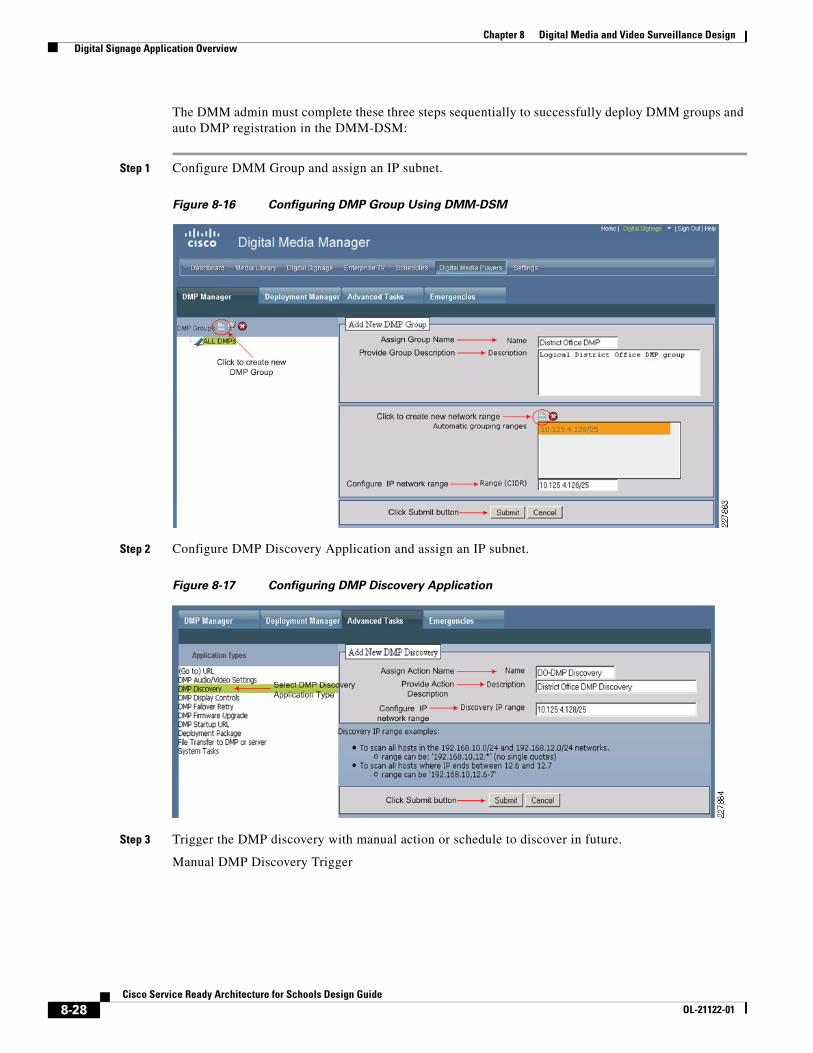
The DMM admin must complete these three steps sequentially to successfully deploy DMM groups and auto DMP registration in the DMM-DSM:
Step 1 Configure DMM Group and assign an IP subnet.
Figure 8-16 Configuring DMP Group Using DMM-DSM
Step 2 Configure DMP Discovery Application and assign an IP subnet.
Figure 8-17 Configuring DMP Discovery Application
Step 3 Trigger the DMP discovery with manual action or schedule to discover in future.
Manual DMP Discovery Trigger
8-28Cisco Service Ready Architecture for Schools Design Guide
OL-21122-01

Chapter 8 Digital Media and Video Surveillance Design Digital Signage Application Overview
Figure 8-18 Triggering DMP Discovery Manually
Refreshing the window in few seconds will reflect the dynamically discovered Cisco DMP that gets automatically registered and grouped as depicted in Figure 8-19. The default name of the auto-registered DMP is the same as their MAC address; the DMM admin must change to reflect with proper name or location name.
Figure 8-19 Dynamically Discovered DMP Discovery Triggered Manually
Scheduling DMP Discovery
Depending on the number of DMP groups, network ranges, and DMP players in the network, the DMP discovery may take some time. In large deployments, it is recommended to schedule Cisco DMP discovery during non-business hours. Scheduling DMP discovery in the network is identical to scheduling the digital signage publishing time. To schedule DMP discovery using Cisco DMM-DSM:
1. Click on Schedules ->Play in Future->Select discovery month and date
2. Select the DMP group to be discovered->Click on Add an Event Button.
3. Select DMP group from Select Group Tab and click OK.
4. Select Advanced Task from Task Type Tab and click on Select Advanced Tasks Tab.
5. Select DMP Discovery from Types and the Action Name and click OK.
6. Configure Start and Stop Action run time and optionally configure repeat value to dynamically discover Cisco DMP based on schedule.
Implementing Digital Signage
Upon successfully discovering and registering the Cisco DMP in the DMM appliance database, the DMM administrator can start preparing to implement digital signage in the network. The provision checklist must include exact content path and schedule to display the content on individual or group DMP in the network. As described earlier, the content must be stored on a Web or CISF server that is physically located on the same campus network as a Cisco DMP. Hence when creating the playlists, it is recommended to specify the URL path where the content is stored.
Publishing digital signage requires three simple configuration step on DMM-DSM as depicted in Figure 8-20:
8-29Cisco Service Ready Architecture for Schools Design Guide
OL-21122-01

Chapter 8 Digital Media and Video Surveillance Design Digital Signage Application Overview
Figure 8-20 Digital Signage Deployment Steps
Executing each step populates content information in DMM in the common repository, provides flexibility to compile playlist with distributed content, and schedules the digital signage publishing time by mapping the playlist to individual or group DMPs. The network topology in Figure 8-21 is used as a reference point to configure each deployment step.
Figure 8-21 Digital Signage Network Topology
WAN
Web/CISFServer
Regional Office
District Office
HDTV
Admin
HDTV
Lobby
HDTV
Cafe
HDTV
ConferenceRoom
Data Center
DMM
creekcountyschools.com
Web/CISFServer
DMSAdmin
2278
68
HDTV
Admin
HDTV
Lobby
HDTV
Cafe
Server Room
creek.rosenelementary.com
8-30Cisco Service Ready Architecture for Schools Design Guide
OL-21122-01
Chapter 8 Digital Media and Video Surveillance Design Digital Signage Application Overview
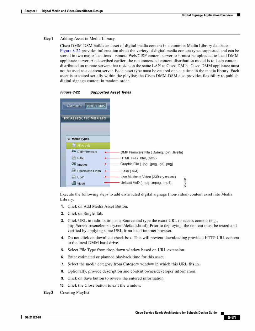
Step 1 Adding Asset in Media Library.
Cisco DMM-DSM builds an asset of digital media content in a common Media Library database. Figure 8-22 provides information about the variety of digital media content types supported and can be stored in two major locations—remote Web/CISF content server or it must be uploaded to local DMM appliance server. As described earlier, the recommended content distribution model is to keep content distributed on remote servers that reside on the same LAN as Cisco DMPs. Cisco DMM appliance must not be used as a content server. Each asset type must be entered one at a time in the media library. Each asset is executed serially within the playlist; the Cisco DMM-DSM also provides flexibility to publish digital signage content in random order.
Figure 8-22 Supported Asset Types
Execute the following steps to add distributed digital signage (non-video) content asset into Media Library:
1. Click on Add Media Asset Button.
2. Click on Single Tab.
3. Click URL in radio button as a Source and type the exact URL to access content (e.g., http://creek.rosenelemetary.com/default.html). Prior to deploying, the content must be tested and verified by applying same URL from local internet browser.
4. Do not click on download check box. This will prevent downloading provided HTTP URL content to the local DMM hard-drive.
5. Select File Type from drop down window based on URL extension.
6. Enter estimated or planned playback time for this asset.
7. Select the media category from Category window in which this URL fits in.
8. Optionally, provide description and content owner/developer information.
9. Click on Save button to review the entered information.
10. Click the Close button to exit the window.
Step 2 Creating Playlist.
8-31Cisco Service Ready Architecture for Schools Design Guide
OL-21122-01

Chapter 8 Digital Media and Video Surveillance Design Digital Signage Application Overview
Playlist is a user-defined logical group that is packaged with the compiled list of distributed digital signage assets which are being added in the shared Media Library database. For example, a playlist can include the intranet home page of the district office and regional school and library books catalog developed in Adobe Flash.
Cisco DMM-DSM provides the flexibility to develop playlists in two different modes—Standalone and Cisco Digital Media Designer (DMD). When the digital signage content is designed and developed outside the DMM-DMD, then DMM administrator must create a standalone playlist.
Cisco Digital Media Designer (DMD) is a Java-based, powerful, drag and drop design tool to create customized digital signage content. Cisco DMM offers pre-designed assets that can be leverage to create personalized design. DMD also offers flexibility to customized horizontal and vertical screen display orientation.
Figure 8-23 Digital Signage Playlist Options
This section provides guideline to implement a standalone playlist. Multiple playlists can be created and associated to an individual or group of DMPs. When designing the asset in the playlist, it is important to remember that the content publishing time and mappings to DMP groups are applied based on per-playlist and not on per-asset basis. The order of playlist execution is done serially based on specified time. Figure 8-24 depicts the playlist order and duration time on per-cycle basis.
Figure 8-24 Digital Signage Display Order and Duration
In a best practice, the playlist can be created based on individual district office or school departments that can provide flexibility to announce the news or any other department specific content at specific time without impacting the playlist for other DMP groups deployed in different departments. Execute the following steps to compile the distributed digital signage asset and estimated or planned run time for each individual asset.
Click on Create Playlist button and follow step-by-step instruction provided in Figure 8-25 to create a complied and distributed digital signage content in playlist.
8-32Cisco Service Ready Architecture for Schools Design Guide
OL-21122-01
Chapter 8 Digital Media and Video Surveillance Design Digital Signage Application Overview
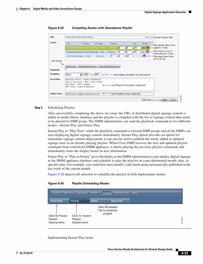
Figure 8-25 Compiling Assets with Standalone Playlist
Step 3 Scheduling Playlist.
After successfully completing the above two steps the URL of distributed digital signage content is added in media library database and the playlist is compiled with the list of signage content that needs to be played for DMP group. The DMM administrator can send the playback command in two different modes—Instant Play and Future Play.
Instant Play or “Play Now” sends the playback command to selected DMP groups and all the DMPs can start displaying digital signage content immediately. Instant Play option provides an option for immediate signage content deployment; it can also be used to publish the newly added or updated signage asset in an already playing playlist. When Cisco DMP receives the new and updated playlist command from centralized DMM appliance, it aborts playing the previous playlist commands and immediately starts the display based on new information.
Future Play or “Play in Future” gives flexibility to the DMM administrator to pre-deploy digital signage in the DMM appliance database and schedule to play the playlist on a pre-determined month, date, or specific time. For example, you could have next month’s café lunch menu automatically published in the last week of the current month.
Figure 8-26 depicts tab selection to schedule the playlist in both deployments modes.
Figure 8-26 Playlist Scheduling Modes
Implementing Instant Play mode
8-33Cisco Service Ready Architecture for Schools Design Guide
OL-21122-01

Chapter 8 Digital Media and Video Surveillance Design Digital Signage Application Overview
Execute the step-by-step procedure as depicted in Figure 8-27 to deploy digital signage instantly in the network. Cisco DMM-DSM provides the flexibility to select single, multiple, or all the DMPs using shift-key to instantaneously publish digital signage in large deployments.
Figure 8-27 Publishing Instant Digital Signage
Implementing Future Play mode
Click on Play in Future tab to schedule a future digital signage content publishing time. Click on Add an Event button from the bottom window and follow the step-by-step configuration guideline as displayed in Figure 8-28 to schedule future signage deployment:
Figure 8-28 Scheduling Signage Deployment
8-34Cisco Service Ready Architecture for Schools Design Guide
OL-21122-01