Embed Size (px)
Citation preview

University of Technology
Electromechanical Engineering Dept.
4th Year / Electromechanical Engineering Branch
DIGITAL MACHINE AND ROBOTICS
2010-2011
Assist. Prof. Dr. Farag Mahel Mohammed
References
1. Niku S.B., Introduction to Robotics, Analysis, Systems, Applications.
Prentice Hall, USA, 2002.
2. Paul, R.P., Robot Manipulators: Mathematics Programming, and
Control, MIT Press. Cambridge 1982.
3. Fu, K.S., Gonzales, R.C., Lee C.S.G., Robotics Control, Sensing,
Vision, and Intelligence, Mc.Graw-Hill International Ed. Singapore,
1988.
4. Craig J. J., Introduction to Robotics, Mechanics and Control, Pearson
Education Inc. International Ed. USA, 2005.
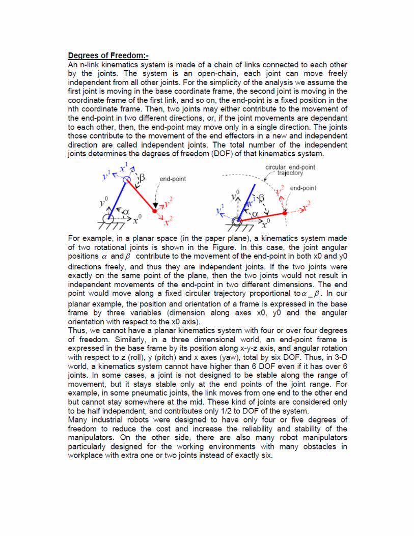
Introduction
The definition for a robot is stated by Robot Institute of America as
“A reprogrammable and multifunctional manipulator, devised for the
transport of materials, parts, tools or specialized systems, with varied and
programmed movements, with the aim of carrying out varied tasks”. This
definition is still far from perfect and needs additional principal properties
such as versatility (having interchangeable geometry) and auto adaptability
to environment (ability to redesign itself to varying environment).
These properties distinct modern robots from the automata machines
those are built for mass production and from products of art of mechanics.
Robots are among the essential tools in today's Industry. They are the
mechanical servants of human being, capable of performing several different
tasks and operations better and safer than the human labor.There are
commercial robots developed for different purposes from cleaning and
inspection to serving human as a pet.
Advantages of Industrial Robots-
Automation using Robotic technology proved itself by increasing the
productivity, safety, efficiency, quality, and consistency of products.
•Robotic devices works in hazardous environments, without needing
workplace comfort such as lighting, air conditioning, noise protection etc.
•They work continuously for very long shifts of work periods without
needing the work requirements of human labor.
•They can be designed more accurate than human.
•In extra-ordinary applications such as medical surgery robots, they can
manage many surgery services which are impossible to be applied by a
human.
•Robots can accomplish processing multiple tasks simultaneously.
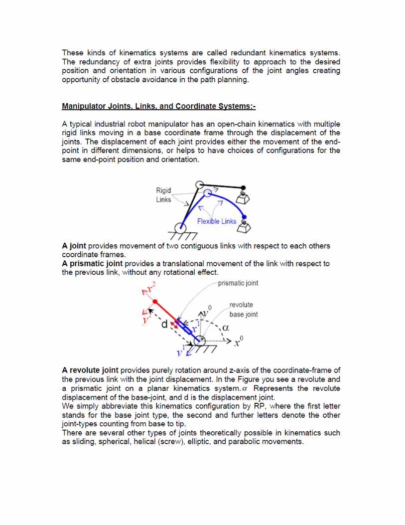
Robotic Components
(1)- Manipulator or rover
Is the main mechanism that provides the ultimate function of the robot. It
consists of a base, the links, the joints and other structural elements that
complete a robot.
(2)- End-effectors
Is the device that is connected to the end of the last joint (hand) of a
manipulator to handle objects, or performs required tasks by a direct contact.
It can be a dexterous hand, a simple gripper, a magnetic clutch or a similar
device that targets a direct contact to the processed material.
(3)- Actuators
Are the source of the force and movements of the manipulator joints.
Stepper motors and hydraulic cylinders provide positional movement, while
servo motor and pneumatic cylinders provide force for the movement of the
manipulator joints, which requires feedback loop for the control of the end-
effectors' position and orientation.
Types of Actuators
The motion of a robot is due to the action of the actuators moving
each of the joints. There are three main types of actuators suitable in
industrial applications named:
1. Electromagnetic actuators.
2. Hydraulic actuators.
3. Pneumatic actuators.
Characteristics of Actuators
1. The power to weight ratio of the actuators is the most important
characteristic in the mechanical design of the robotic systems. The
power to weight ratio of most electrical actuators are average,
however, stepper motors that provide positional stiffness are generally
heavier than dc-servomotors, which provide joint-torque. The power
of the hydraulic systems is the highest, ranging from 50 to 5000 psi
(pound per square inch, 14psi=1kg/cm2).
2. The stiffness is the resistance of a material against elastic
deformation. Compliance is the opposite concept, the tendency of
deforming under a load. Pneumatic systems have very low stiffness
due to the compressibility of gases. A typical hydraulic fluid has much
lower elasticity, providing a higher stiffness in hydraulic actuators.
This property makes a hydraulic actuator a directly position-
determining device.
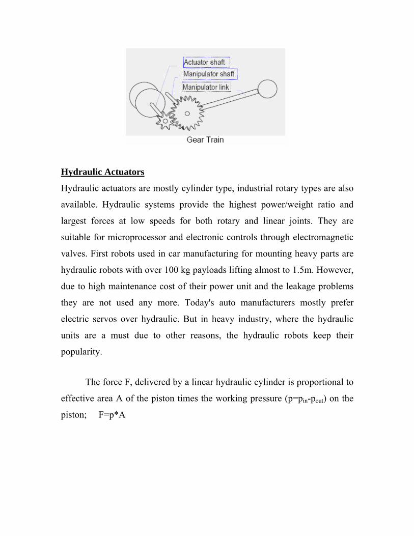
3. The torque supplied by an actuator mostly does not match to the
desired torque required to move the joint. In such cases, a gear-train is
necessary to match the joint torque to the actuator torque. A gear train
with gear ratio N provides the reduction of speed n times, while
increasing the torque with the same ratio.
Hydraulic Actuators
Hydraulic actuators are mostly cylinder type, industrial rotary types are also
available. Hydraulic systems provide the highest power/weight ratio and
largest forces at low speeds for both rotary and linear joints. They are
suitable for microprocessor and electronic controls through electromagnetic
valves. First robots used in car manufacturing for mounting heavy parts are
hydraulic robots with over 100 kg payloads lifting almost to 1.5m. However,
due to high maintenance cost of their power unit and the leakage problems
they are not used any more. Today's auto manufacturers mostly prefer
electric servos over hydraulic. But in heavy industry, where the hydraulic
units are a must due to other reasons, the hydraulic robots keep their
popularity.
The force F, delivered by a linear hydraulic cylinder is proportional to
effective area A of the piston times the working pressure (p=pin-pout) on the
piston; F=p*A
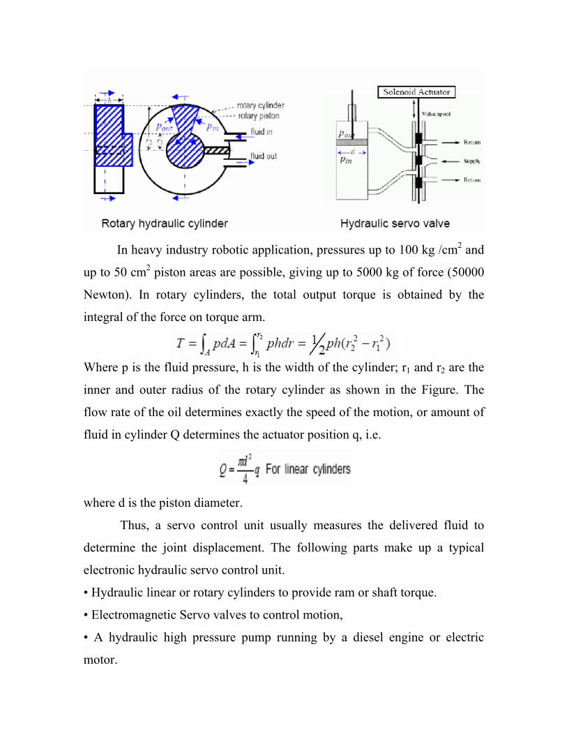
In heavy industry robotic application, pressures up to 100 kg /cm2 and
up to 50 cm2 piston areas are possible, giving up to 5000 kg of force (50000
Newton). In rotary cylinders, the total output torque is obtained by the
integral of the force on torque arm.
Where p is the fluid pressure, h is the width of the cylinder; r1 and r2 are the
inner and outer radius of the rotary cylinder as shown in the Figure. The
flow rate of the oil determines exactly the speed of the motion, or amount of
fluid in cylinder Q determines the actuator position q, i.e.
where d is the piston diameter.
Thus, a servo control unit usually measures the delivered fluid to
determine the joint displacement. The following parts make up a typical
electronic hydraulic servo control unit.
• Hydraulic linear or rotary cylinders to provide ram or shaft torque.
• Electromagnetic Servo valves to control motion,
• A hydraulic high pressure pump running by a diesel engine or electric
motor.
• Returned fluid and pressurized fluid reservoirs,
• Cooling system fans and radiators to remove the dissipated heat.
Advantages of Hydraulic actuator:
1. Large lift capacity.
2. High power to weight ratio.
3. Moderate speeds.
4. Oil is incompressible, lead to stiff structure.
5. Very good servo control can be achieved.
6. Self lubricating and self cooling.
7. Operate in stalled condition with no damage.
8. Fast response.
9. Smooth operation at low speed.
Disadvantages:
1. Hydraulic systems are expensive.
2. Maintenance problems with seals causing leakage.
3. Not suitable for high speed cycling.
4. Need for remote power source which uses floor space.
5. Need for a return line.
Pneumatic actuators
Pneumatic cylinder construction makes extensive use of aluminum
and other nonferrous alloys to reduce weight and the corrosive effects of air.
Aluminum cylinders also transfer heat efficiently.
Advantages of pneumatic actuators:
1. Relatively in expensive.
2. High speed.
3. No return line required.
Disadvantages:
1. Compressibility of air limits control and accuracy aspects.
2. Noise pollution from exhausts.
3. Leakage of air can be of concern.
4. Difficulties with control of speeds.
Electromagnetic actuators:
Electromagnetic actuators are mostly solenoid or relay, The basic law
beneath the electric motors is the force F generated on a current conducting
wire in a magnetic field B, i.e., F= I×B , where I is the vector of current
along the wire. A wire rotating in the magnetic field produces a voltage.
Similarly, a motion of the current carrying wire in a magnetic field against
this torque generates an induced voltage V at the terminals of the wire. A
DC motor uses this principle by switching the current with a commentator to
keep the current always in the highest region of the magnetic field. An AC
motor uses stationary wires (stator), while generating an induced voltage in
the rotating coils (rotor) to obtain a rotating magnetic field.
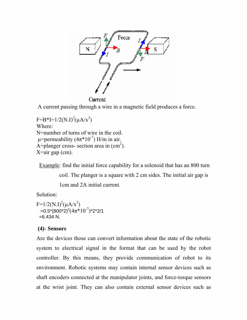
A current passing through a wire in a magnetic field produces a force. F=B*I=1/2(N.I)2(µA/x2) Where: N=number of turns of wire in the coil. µ=permeability (4π*10-7) H/m in air. A=planger cross- section area in (cm2). X=air gap (cm).
Example: find the initial force capability for a solenoid that has an 800 turn
coil. The planger is a square with 2 cm sides. The initial air gap is
1cm and 2A initial current.
Solution:
F=1/2(N.I)2(µA/x2) =0.5*(800*2)2(4π*10-7)*2*2/1 =6.434 N. (4)- Sensors
Are the devices those can convert information about the state of the robotic
system to electrical signal in the format that can be used by the robot
controller. By this means, they provide communication of robot to its
environment. Robotic systems may contain internal sensor devices such as
shaft encoders connected at the manipulator joints, and force-torque sensors
at the wrist joint. They can also contain external sensor devices such as
vision systems to detect the end-effectors location, proximity sensors at
several locations to detect the state of materials and devices in the work
environment.
•Human senses: sight, sound, touch, taste, and smell provide us vital
information to function and survive
•Robot sensors: measure robot configuration/condition and its environment
and send such information to robot controller as electronic signals (e.g., arm
position, presence of toxic gas)
•Robots often need information that is beyond 5 human senses (e.g., ability
to: see in the dark, detect tiny amounts of invisible radiation, measure
movement that is too small or fast for the human eye to see)
1. Vision Sensor: e.g., to pick bins, perform inspection, etc. Part-
Picking: Robot can handle work pieces that are randomly piled by
using 3-D vision sensor. Since alignment operation, a special parts
feeder, and an alignment palette are not required, an automatic system
can be constructed at low cost.
2. Strain Gage and FSRs: A strain gage is a directional wound wire
that changes resistance due to change of wire length and cross section.
Usually four strain gage resistors in bridge configuration provide one
reliable ratio metric measurement of the mechanical deformation. A
force sensing resistor (FSR) is available by Interlink Electronics. The
resistance of the polymer thick-film device changes from 500K to 1K
while the applied force is changing from 0.010 to 10 kg (0.1 to 100N).
3. Force Sensor: Resistive, piezoelectric, capacitive and magnetic force
sensors mostly convert the force to a small displacement by an elastic
deformation of sensor substrate, and detect the electrical or optical
effect of this deformation. Piezoelectric ceramic material develops a
charge on material surface proportional to its deformation. Three pairs
of strain gages may give torque and force readings in three dimension
4. Velocity and Acceleration Sensors : A tachogenerator is a small
voltage generator with a permanent magnet that generates a voltage
proportional to its rotor velocity. However, in robotics the joint speed
is simply calculated from the derivative of the joint displacement. In
an accelerometer, the compounds f the force exerted by a mass on
three axes are measured by six silicon strain o gages. Again, the
accelerometers are rarely used in applications since the calculation of
the acceleration is possible using the rate of change of displacement.
5. Infrared and Light Sensors : Infrared sensors are an assembly of
infrared light source and an infrared sensitive diode or transistor,
which produces proportional electrical signals to the light intensity.
An infrared LED serves as an inexpensive infrared light source, and
an infrared phototransistor reads the intensity of the transferred or
reflected light. They are also used for data transmission between
electrically isolated digital circuits against high voltages.
An array of LED's provides multiple readings with a single photo transistor
by means of time multiplexing, which also solves the phototransistor
dependent parameter differences in the analog readings. Whenever possible,
the sensor system is built to work on digital signals; either light exists or
does not exist. Optical focusing and moving mirrors may provide very
precise sweeping of the search area in very short time periods, for optical
range finding and proximity detection purposes. Optical sensing is widely
used in shaft encoders and in proximity switches, since they have no wearing
parts at all.
6. Proximity Sensors
A proximity sensor is a device which provides an electric signal
(switch status, voltage, current, resistive change etc.) when the sensor is in a
distance range to a specified target.
• A micro switch with a long flexible lever arm can be used as proximity
sensor by mechanical contact.
• In magnetic proximity sensors, the magnetic field of a permanent magnet
turns a reed relay on or off when the magnet is close enough to the reed-
relay.
• In inductive proximity sensors, the distance to a magnetic material is
detected by an unbalance in magnetic fields of an induction coil setup.
•In optical proximity sensors, the intensity of the reflected or obstructed
infrared beam indicates the distance to the reflecting or obstructing
material.
•In ultrasonic proximity sensors, echo or transmission of an ultrasound wave
indicates the existence of an object.
Other types of proximity sensors are used in special constraints of
environment such as noise, electrical disturbance, full darkness
requirements, etc. There are capacitive, Eddy current, and Laser proximity
sensors and range finders available for the industrial use. (5)- Control of industrial robots
Can be studied in various hierarchical levels
•Top level of control is the organization level, which accepts and interprets
input commands and related feedback from the system, defines the task to be
executed, then segments the task into subtasks in the appropriate order of
execution.
•The medium level is a coordination level, in which the instructions
(subtasks) are processed together with feedbacks from the process in order to
generate the lowest level commands (including desired trajectories) which
should be followed by the manipulator.
•The lowest level of control is the hardware control level of manipulator,
and involves execution of desired motion. Hardware control level needs a
model of the manipulator motion, and a performance criterion or cost
function for the design of the joint controllers.
(a)- Controller
•Provide necessary intelligence to control the manipulator/mobile robot.
•Process the sensory information and compute the control commands for the
actuators to carry out specified tasks.
Controller is a device that collects signals from the position sensors. It
processes them and generates the actuator signals to move the manipulator
joints in harmony, so that the manipulator tracks the pre-programmed
motion. The controller provides the hardware control level of the
manipulator.
(b)- Processor is generally a dedicated computer system built of many
microprocessors or microcontrollers to accomplish the higher level control
action.
The processor contains the storage medium to keep the programs. It provides
the joint positions to the controller for a smooth movement of the
manipulator along the programmed trajectories.
(c)- Software of robotic systems can be grouped in three main levels.
• The operating system operates the computer.
• The coordination level programs keep the manipulator in the trajectory.
•The organization level programs provide switching between the
coordination level programs depending on the feedback collected by the
sensors in the robot environment. This level provides the intelligence of the
robotic system, which means to act properly on the changing environmental
conditions.
Robot Technical Specifications
Followings are the significant characteristics of a typical industrial
robot.
1. The workspace is the geometrical space defined by all possible end-point
positions of a robot mechanism. The shape of the workspace depends on the
link and joint types and joint displacement limitations. The accuracy and
repeatability of a robot is valid only in the workspace described by the
manufacturer.
2. Payload is the maximum load to be carried by the robot while satisfying
all technical specifications. Mostly, a robot can hold four to tenfold of its
payload if in that application the specified accuracy and speed is not
important. Typical payload to weight ratio of the industrial robots is in the
range of 1/5 to1/10.
3. Reach is the farthest distance a robot can expand its arm in the
workspace. A painting robot which does not require high accuracy may have
longer reach than the assembly robots. A typical assembly robot may have
reach in the range from 0.40 to 0.80 meters.
4. Precision (validity) is the accuracy of the manipulator end-point position.
Accuracy of a manipulator is limited both by the flexible bending of the
manipulator mechanism, and also by the accuracy of the position feedback
encoders, actuators and controller.
5. Repeatability (variability) error is the maximum deviation of position
between the trials to move the endpoint of the robot to the same point
repeatedly. For example, if we make 100 trials to move to a point and the tip
moves maximum 1mm away from that point, the repeatability error of the
robot for that point is 1mm. Most industrial robots have repeatability around
0.05 mm.
Robot Programming
A typical industrial robot is mostly programmed in one of the
following four modes:
1. Physical Setup Mode is typical programming method for very simple
pick-and-place manipulators, where programmable logic controllers (PLC's),
proximity and limit switches, event switches, and timers are used to perform
cyclic operation of the manipulator for a desired task.
2. Walking Through Mode is an elaborated teach mode. The operator
teaches the manipulator which way to move by forcing the manipulator to
move in the desired way. This is the most common programming method for
playback robots. It is conveniently used for painting and assembly robots.
3. Lead Through or Teach Mode is for continuous path playback robots
and a typical programming mode of a manipulator with positional control
capability. Manipulator is moved to the desired positions by the aid of a
teach pendant (a control keypad), and the desired positions are stored into
program memory in the desired sequence. After teaching is accomplished,
controller is set to playback mode, in which the controller moves the
manipulator point to point to the desired positions.
4. Software Mode is off-line program writing mode using a text editor or
graphical interface. Programming in software mode requires knowledge on
operating system and robot languages. Sensor information is easily included
to the programming, and the task definitions can be extracted using the data
of the processed objects from the computer-aided-design (CAD) database. It
is the most sophisticated, and the most versatile way of programming a
robot. Most industrial robots have more than one programming modes, and,
the most convenient programming mode depends to the task to be
programmed. Robot Programming Languages
Robot language is the specific high level programming language of a
robot system. Each manufacturer designs a robot language for a family of
robot model. These languages are at different levels of sophistication
depending on the type of applications. Many of them are based on common
programming languages such as COBOL, Basic, C, and FORTRAN. Other
application specific languages are either interpreter based, or compiled to the
assembler or common high level languages.
1. Interpreter languages are easy to trace and debug since each
command can be interpreted step by step, but they are slow because
each line is executed sequentially and independently. Many industrial
robots use their own interpreter languages.
2. Compiler based languages are compiled to machine language (object
code) before their execution. These programs are much faster and
efficient, but debugging of these languages requires more effort since
the program cannot be executed in single-step mode. Some languages
have both a compiler for efficient usage, and an interpreter for debug
mode. It is possible to test a program in single-step mode, and then
execute it at much faster speeds.
3. Machine Language level is the lowest possible programming level of
programmable robots. It is the primitive programming language of the
processor. All programs are either compiled to machine language, or
interpreted by an interpreter that runs in machine language. Programs
directly written at machine level may be very efficient and fast, but
debugging and programming is extremely difficult.
4. Point-to-Point level languages (i.e. Cincinnati "Milacron") are very
primitive, simple to program easy to use interpreter languages. The
points to be followed are simply listed sequentially mostly in task-
frame. It generally lacks structuring and modularity (very weak in
branching, and conditional statements).
5. Primitive Motion Level languages are interpreter based languages
equipped with programming modularity. They have commands for
sensory data processing and branching, which makes the language
suitable for simple intelligent applications.
6. Structured Programming Level languages are compiler based
powerful languages which allow sophisticated programming.
However, they are more difficult to learn.
7. Task Oriented Languages are the top level of the robotic
programming which has not yet been implemented by any
manufacturer. Instead of programming a robot task in detail with each
and every step necessary to complete the task, the user will only
specify which task to do, and the controller (or interpreter) will create
all other necessary steps of the task. IBM in 1980's proposed it, but
never accomplished a fully working system. It is still an open research
area to develop a task oriented language.