Embed Size (px)
Citation preview

Copyright © 2004 Mitsubishi Digital Electronics, Inc.9351 Jeronimo Road, Irvine CA 92618-1904
2004V26 Chassis
V26 Chassis V26+ Chassis V26++ ChassisWD-52525 WD-52725 WD-52825WD-62525 WD-62725 WD-62825
Digital Light Processing�Projection Television

1
I
Chapter 1 - IntroductionV26 Models ..................................................................................................................................... 1-1HDMI� & CableCARD� ................................................................................................................. 1-2RF Antenna Inputs ........................................................................................................................... 1-3PVR (Personal Video Recorder) ....................................................................................................... 1-3DLP� Fundamentals ...................................................................................................................... 1-3Light Path Changes ......................................................................................................................... 1-5Servicing .......................................................................................................................................... 1-7
Chapter 2 - DisassemblyFront Disassembly........................................................................................................................... 2-1Rear Disassembly ........................................................................................................................... 2-4Accessing the Chassis .................................................................................................................... 2-5Accessing PWB-POWER................................................................................................................ 2-6Chassis Removal ............................................................................................................................. 2-6Accessing & Disconnecting the Lamp Ballast .................................................................................. 2-7
Chapter 3 - Light Engine ReplacementLight Engine Assembly .................................................................................................................... 3-1Airduct Removal ............................................................................................................................... 3-2Light Engine removal screws............................................................................................................ 3-2Light Engine Removable Parts ......................................................................................................... 3-3Installing the Replacement Light Engine .......................................................................................... 3-4
Chapter 4 - Service AdjustmentsOption Menu .................................................................................................................................... 4-1Service Adjustment Mode ................................................................................................................ 4-1Internal Test Pattern ......................................................................................................................... 4-2Service Adjustments ........................................................................................................................ 4-2Position Adjustments ....................................................................................................................... 4-2Mechanical Adjustments .................................................................................................................. 4-3
Required Disassembly ................................................................................................................. 4-3Rotation Adjustment..................................................................................................................... 4-4Keystone Adjustments ................................................................................................................. 4-6
Data Transfer & Data Reset ............................................................................................................. 4-7Chapter 5 - Troubleshooting
Replaceable Components ................................................................................................................ 5-1Normal Front Panel LED Indications ................................................................................................ 5-2Abnormal Front Panel LED Indications............................................................................................. 5-2Error Code Operational Check ......................................................................................................... 5-3Lamp Troubleshooting Procedure ..................................................................................................... 5-4POWER-PWB Troubleshooting ....................................................................................................... 5-4
Chapter 6 - Block DiagramsPower Supply .................................................................................................................................. 6-2Video Circuitry ................................................................................................................................. 6-3Sound Circuitry ................................................................................................................................ 6-6Control Circuitry ............................................................................................................................... 6-8
V26 Technical TrainingTable of Contents

II

II
1-1
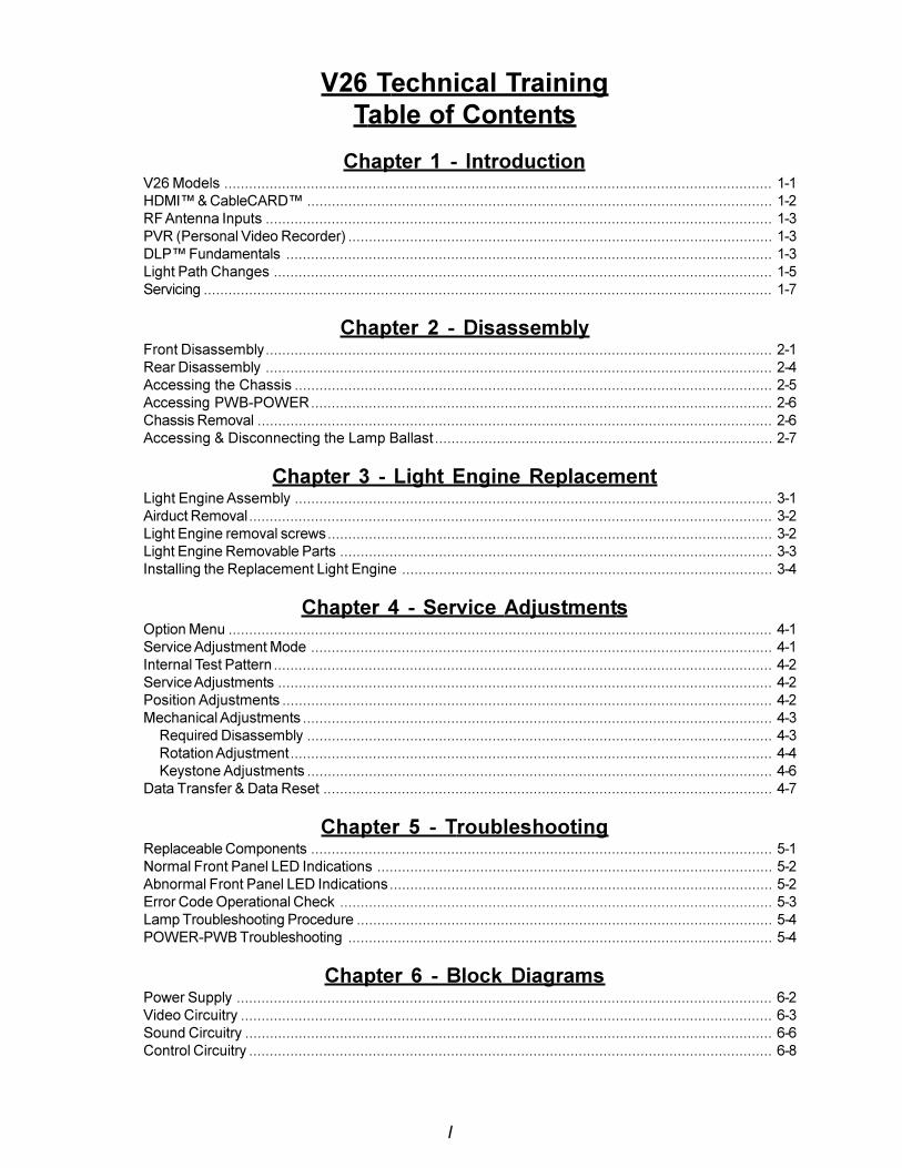
WD-52825WD-52525 WD-52725
Chapter 1Introduction
The new V26 Chassis types are all Integrated HD/CableReady TVs. There are three V26 chassis types, V26,V26+ and V26++. The specific models for each chas-sis type are given in Table 1-1.All of the models are table top models, but matchingbases are available for each model. The 52 inch modelfor each chassis type is shown above, with it's matchingbase.All models feature:
� Integrated HD/Cable Ready Circuitry
� DLPTM Light Engine� CableCARDTM Slot� Memory Card Reader� HDMI Input
The V26+ models add:� Anti-Glare Diamond Shield�� TV Guide On Screen ® (when available)
The 26++ models also include HD PVR (High Defini-tion Personal Video Recorder) with a 120 GB HardDisc Drive.
Table 1-1: V26 Chassis Series Models
V26 Chassis V26+ Chassis V26++ ChassisWD-52525 WD-52725 WD-52825WD-62525 WD-62725 WD-62825
1-2
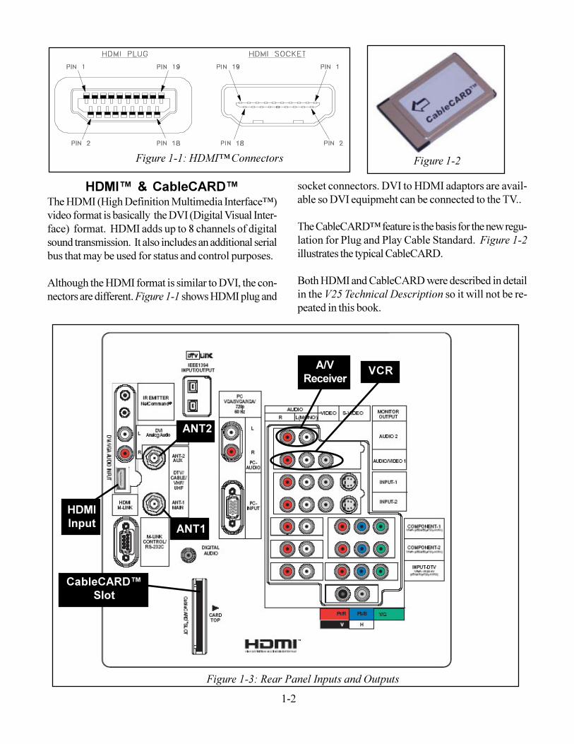
HDMI� & CableCARD�The HDMI (High Definition Multimedia Interface�)video format is basically the DVI (Digital Visual Inter-face) format. HDMI adds up to 8 channels of digitalsound transmission. It also includes an additional serialbus that may be used for status and control purposes.Although the HDMI format is similar to DVI, the con-nectors are different. Figure 1-1 shows HDMI plug and
Figure 1-1: HDMI� Connectors Figure 1-2socket connectors. DVI to HDMI adaptors are avail-able so DVI equipmeht can be connected to the TV..The CableCARD� feature is the basis for the new regu-lation for Plug and Play Cable Standard. Figure 1-2illustrates the typical CableCARD.Both HDMI and CableCARD were described in detailin the V25 Technical Description so it will not be re-peated in this book.
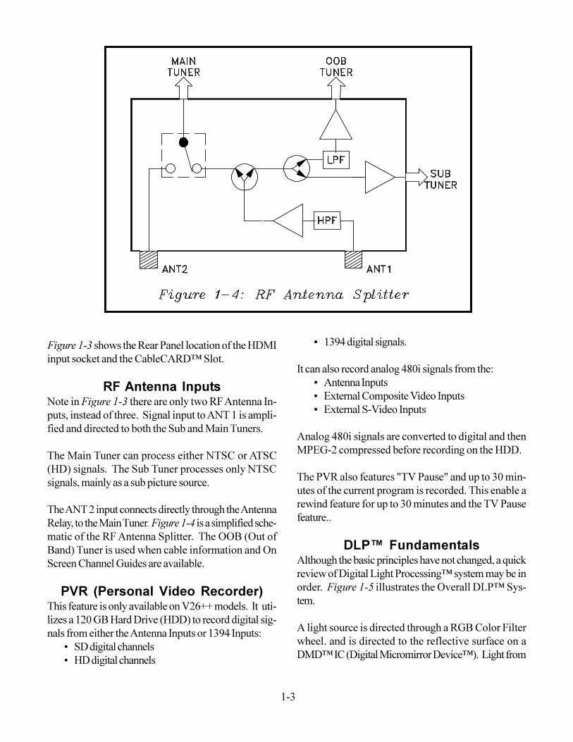
Figure 1-3: Rear Panel Inputs and Outputs
CableCARD�Slot
HDMIInput
ANT2
ANT1
A/VReceiver VCR
1-3
Figure 1-3 shows the Rear Panel location of the HDMIinput socket and the CableCARD� Slot.
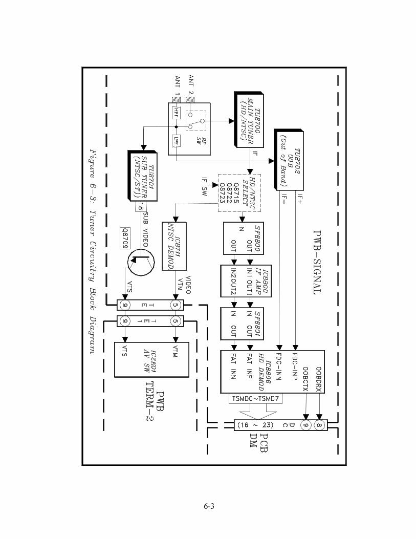
RF Antenna InputsNote in Figure 1-3 there are only two RF Antenna In-puts, instead of three. Signal input to ANT 1 is ampli-fied and directed to both the Sub and Main Tuners.The Main Tuner can process either NTSC or ATSC(HD) signals. The Sub Tuner processes only NTSCsignals, mainly as a sub picture source.The ANT 2 input connects directly through the AntennaRelay, to the Main Tuner. Figure 1-4 is a simplified sche-matic of the RF Antenna Splitter. The OOB (Out ofBand) Tuner is used when cable information and OnScreen Channel Guides are available.
PVR (Personal Video Recorder)This feature is only available on V26++ models. It uti-lizes a 120 GB Hard Drive (HDD) to record digital sig-nals from either the Antenna Inputs or 1394 Inputs:
� SD digital channels� HD digital channels
� 1394 digital signals.It can also record analog 480i signals from the:
� Antenna Inputs� External Composite Video Inputs� External S-Video Inputs
Analog 480i signals are converted to digital and thenMPEG-2 compressed before recording on the HDD.The PVR also features "TV Pause" and up to 30 min-utes of the current program is recorded. This enable arewind feature for up to 30 minutes and the TV Pausefeature..
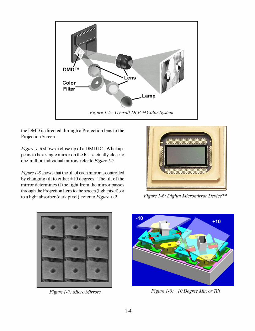
DLP� FundamentalsAlthough the basic principles have not changed, a quickreview of Digital Light Processing� system may be inorder. Figure 1-5 illustrates the Overall DLP� Sys-tem.A light source is directed through a RGB Color Filterwheel. and is directed to the reflective surface on aDMD� IC (Digital Micromirror Device�). Light from
1-4
DMD�ColorFilter
Lens
Lamp
Figure 1-5: Overall DLP� Color System
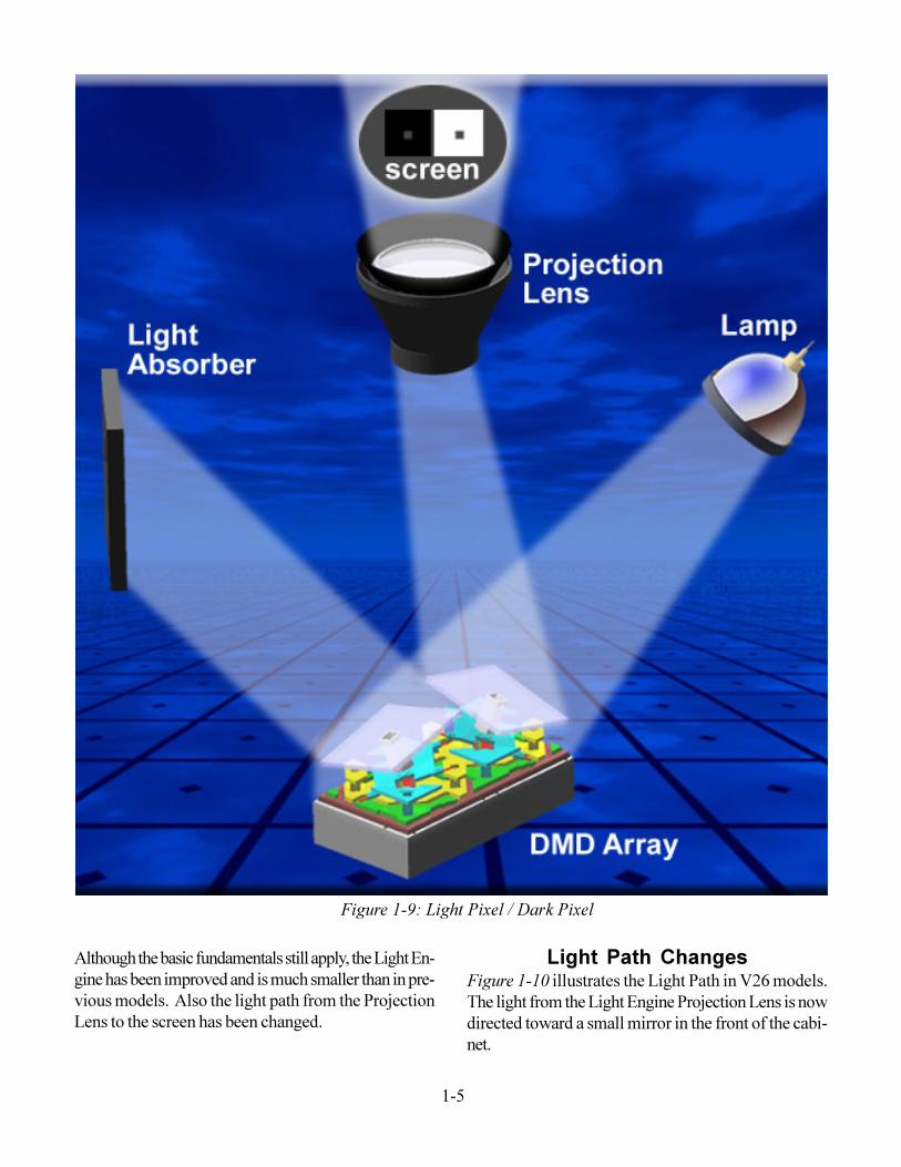
the DMD is directed through a Projection lens to theProjection Screen.Figure 1-6 shows a close up of a DMD IC. What ap-pears to be a single mirror on the IC is actually close toone million individual mirrors, refer to Figure 1-7.Figure 1-8 shows that the tilt of each mirror is controlledby changing tilt to either ±10 degrees. The tilt of themirror determines if the light from the mirror passesthrough the Projection Lens to the screen (light pixel), orto a light absorber (dark pixel), refer to Figure 1-9. Figure 1-6: Digital Micromirror Device�
Figure 1-7: Micro Mirrors
-10 +10
Figure 1-8: ±10 Degree Mirror Tilt
1-5
Although the basic fundamentals still apply, the Light En-gine has been improved and is much smaller than in pre-vious models. Also the light path from the ProjectionLens to the screen has been changed.
Figure 1-9: Light Pixel / Dark PixelLight Path Changes
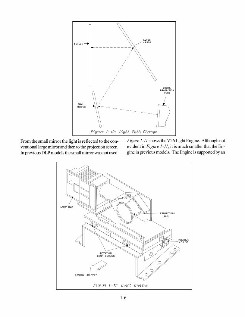
Figure 1-10 illustrates the Light Path in V26 models.The light from the Light Engine Projection Lens is nowdirected toward a small mirror in the front of the cabi-net.
1-6
From the small mirror the light is reflected to the con-ventional large mirror and then to the projection screen.In previous DLP models the small mirror was not used.
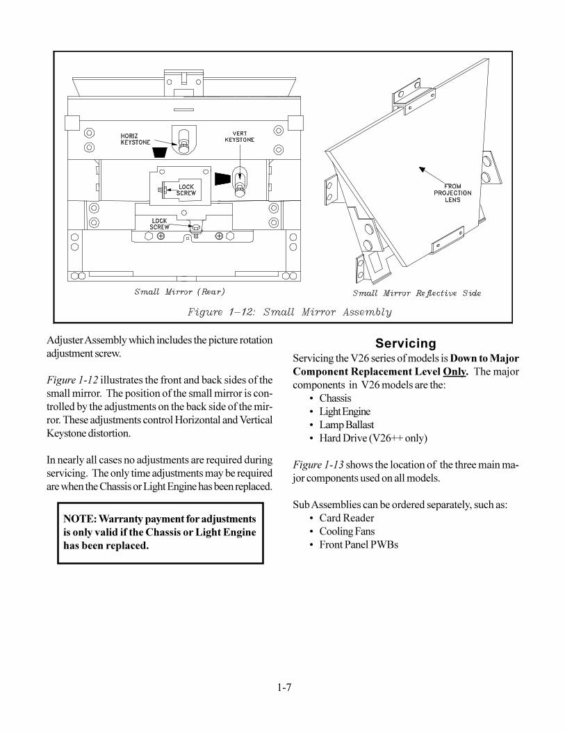
Figure 1-11 shows the V26 Light Engine. Although notevident in Figure 1-11, it is much smaller that the En-gine in previous models. The Engine is supported by an
1-7
Adjuster Assembly which includes the picture rotationadjustment screw.Figure 1-12 illustrates the front and back sides of thesmall mirror. The position of the small mirror is con-trolled by the adjustments on the back side of the mir-ror. These adjustments control Horizontal and VerticalKeystone distortion.In nearly all cases no adjustments are required duringservicing. The only time adjustments may be requiredare when the Chassis or Light Engine has been replaced.
NOTE: Warranty payment for adjustmentsis only valid if the Chassis or Light Enginehas been replaced.
ServicingServicing the V26 series of models is Down to MajorComponent Replacement Level Only. The majorcomponents in V26 models are the:
� Chassis� Light Engine� Lamp Ballast� Hard Drive (V26++ only)
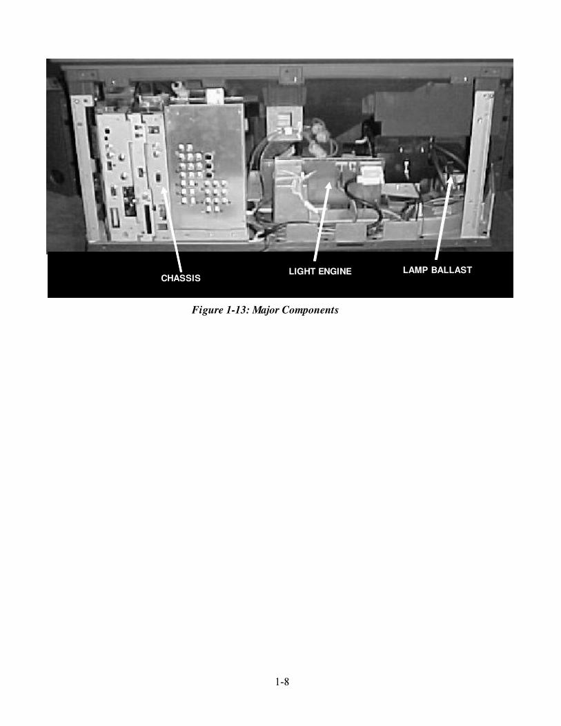
Figure 1-13 shows the location of the three main ma-jor components used on all models.Sub Assemblies can be ordered separately, such as:
� Card Reader� Cooling Fans� Front Panel PWBs
1-8
CHASSISLIGHT ENGINE LAMP BALLAST
Figure 1-13: Major Components
2-1
Servicing the V26 models consists mainly of replacingmajor components. These disassembly procedures aregeared to accessing and replacing these major compo-nents:
� Light Engine� Chassis� Lamp Ballast� PWB-POWER (Optional)
To order any of the major components, T/A (TechnicalAdvisory) authorizations is required.
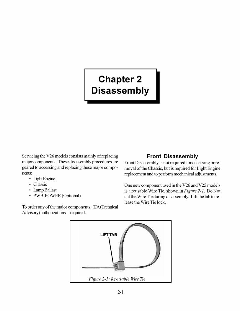
Front DisassemblyFront Disassembly is not required for accessing or re-moval of the Chassis, but is required for Light Enginereplacement and to perform mechanical adjustments.One new component used in the V26 and V25 modelsis a reusable Wire Tie, shown in Figure 2-1. Do Notcut the Wire Tie during disassembly. Lift the tab to re-lease the Wire Tie lock.
Figure 2-1: Re-usable Wire Tie
LIFT TAB
Chapter 2Disassembly
2-2
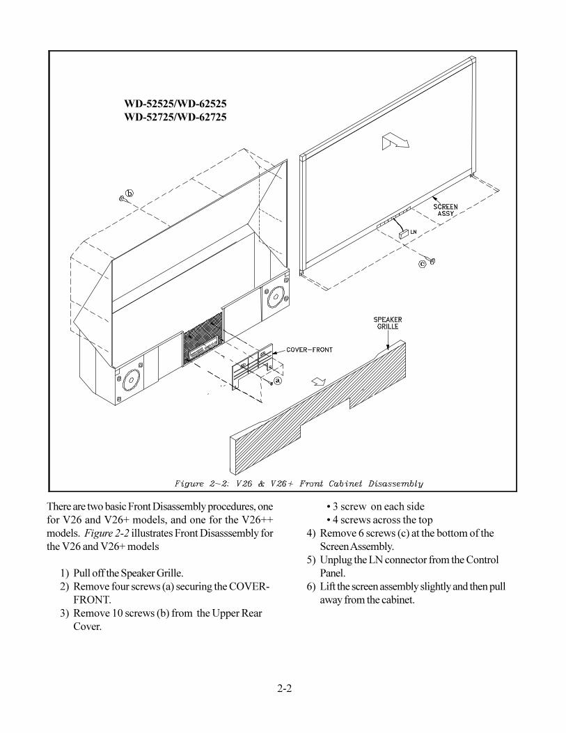
There are two basic Front Disassembly procedures, onefor V26 and V26+ models, and one for the V26++models. Figure 2-2 illustrates Front Disasssembly forthe V26 and V26+ models
1) Pull off the Speaker Grille.2) Remove four screws (a) securing the COVER-
FRONT.3) Remove 10 screws (b) from the Upper Rear
Cover.
� 3 screw on each side� 4 screws across the top
4) Remove 6 screws (c) at the bottom of theScreen Assembly.
5) Unplug the LN connector from the ControlPanel.
6) Lift the screen assembly slightly and then pullaway from the cabinet.
WD-52525/WD-62525WD-52725/WD-62725
2-3
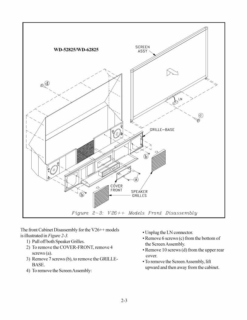
The front Cabinet Disassembly for the V26++ modelsis illustrated in Figure 2-3.
1) Pull off both Speaker Grilles.2) To remove the COVER-FRONT, remove 4
screws (a).3) Remove 7 screws (b), to remove the GRILLE-
BASE.4) To remove the Screen Assembly:
� Unplug the LN connector.� Remove 6 screws (c) from the bottom of the Screen Assembly.� Remove 10 screws (d) from the upper rear cover.� To remove the Screen Assembly, lift upward and then away from the cabinet.
WD-52825/WD-62825
2-4
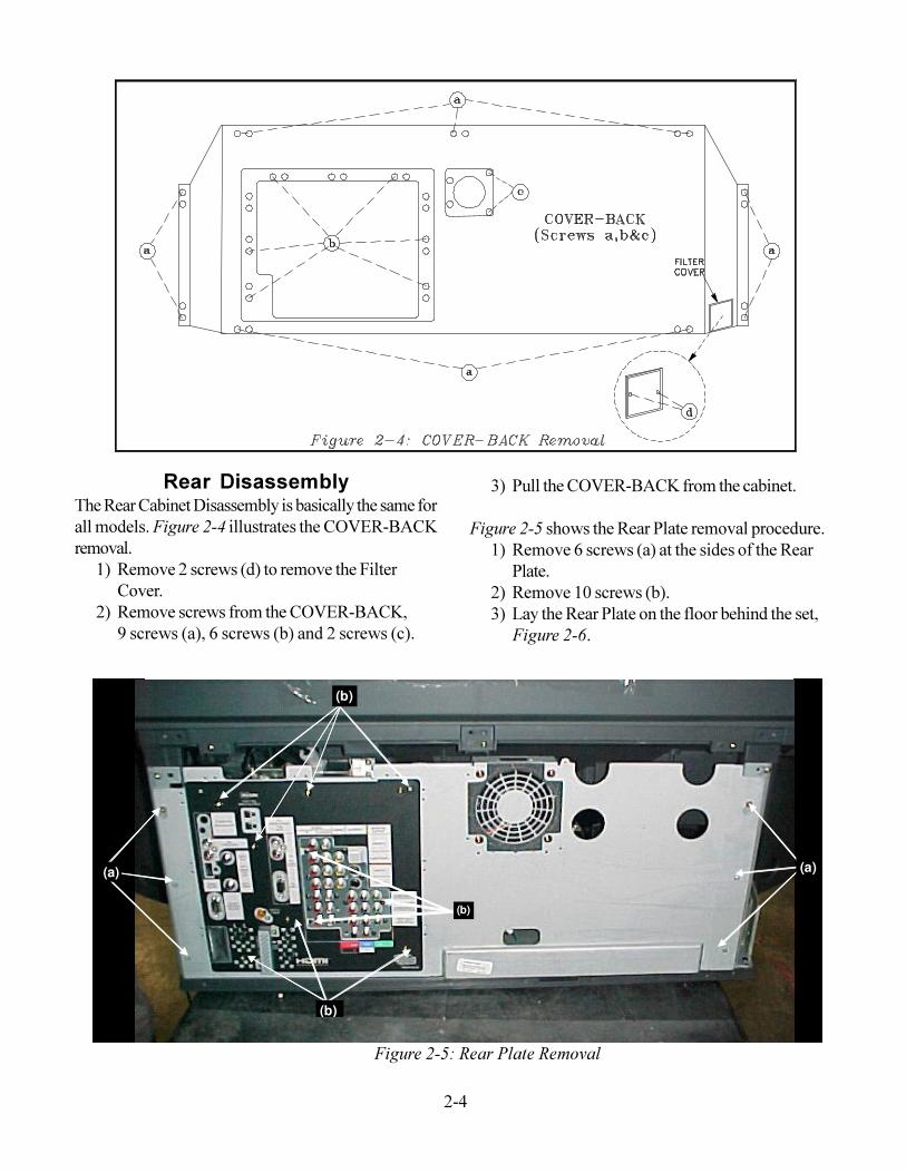
Rear DisassemblyThe Rear Cabinet Disassembly is basically the same forall models. Figure 2-4 illustrates the COVER-BACKremoval.
1) Remove 2 screws (d) to remove the FilterCover.
2) Remove screws from the COVER-BACK,9 screws (a), 6 screws (b) and 2 screws (c).
3) Pull the COVER-BACK from the cabinet.Figure 2-5 shows the Rear Plate removal procedure.
1) Remove 6 screws (a) at the sides of the RearPlate.
2) Remove 10 screws (b).3) Lay the Rear Plate on the floor behind the set,
Figure 2-6.
Figure 2-5: Rear Plate Removal
(a) (a)
(b)
(b)
(a) (a)
(b)
(b)
(b)
2-5
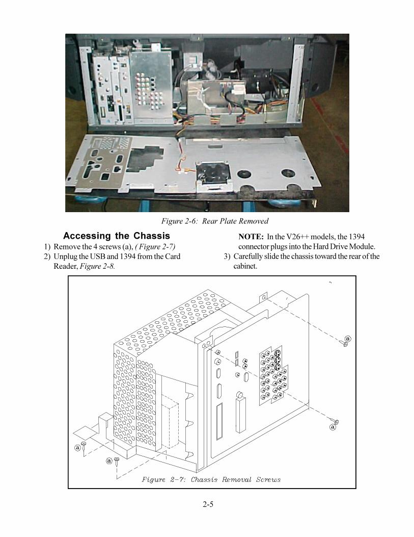
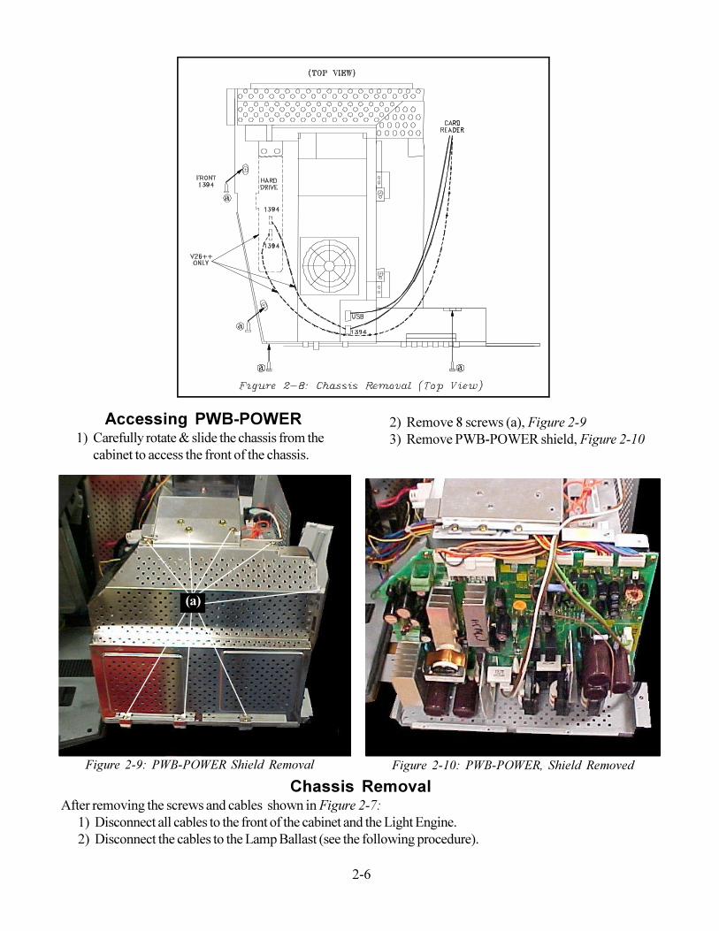
Accessing the Chassis1) Remove the 4 screws (a), ( Figure 2-7)2) Unplug the USB and 1394 from the Card
Reader, Figure 2-8.
NOTE: In the V26++ models, the 1394connector plugs into the Hard Drive Module.
3) Carefully slide the chassis toward the rear of thecabinet.
Figure 2-6: Rear Plate Removed
2-6
Accessing PWB-POWER1) Carefully rotate & slide the chassis from the
cabinet to access the front of the chassis.
Figure 2-10: PWB-POWER, Shield Removed
2) Remove 8 screws (a), Figure 2-93) Remove PWB-POWER shield, Figure 2-10
Chassis RemovalAfter removing the screws and cables shown in Figure 2-7:
1) Disconnect all cables to the front of the cabinet and the Light Engine.2) Disconnect the cables to the Lamp Ballast (see the following procedure).
(a)
Figure 2-9: PWB-POWER Shield Removal
2-7
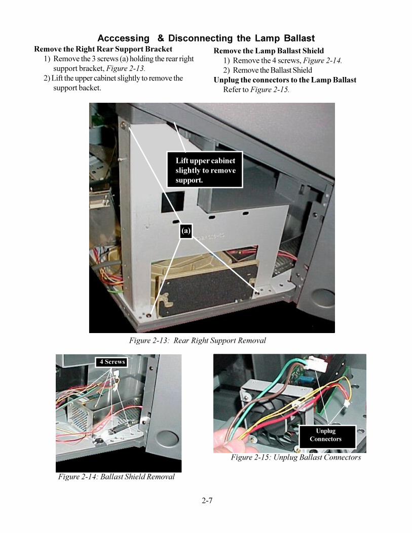
Remove the Right Rear Support Bracket1) Remove the 3 screws (a) holding the rear right
support bracket, Figure 2-13.2) Lift the upper cabinet slightly to remove the
support backet.
(a)
Figure 2-13: Rear Right Support Removal
Lift upper cabinetslightly to removesupport.
Acccessing & Disconnecting the Lamp BallastRemove the Lamp Ballast Shield
1) Remove the 4 screws, Figure 2-14.2) Remove the Ballast Shield
Unplug the connectors to the Lamp BallastRefer to Figure 2-15.
4 Screws
Figure 2-14: Ballast Shield Removal
UnplugConnectors
Figure 2-15: Unplug Ballast Connectors

2-8
3-1
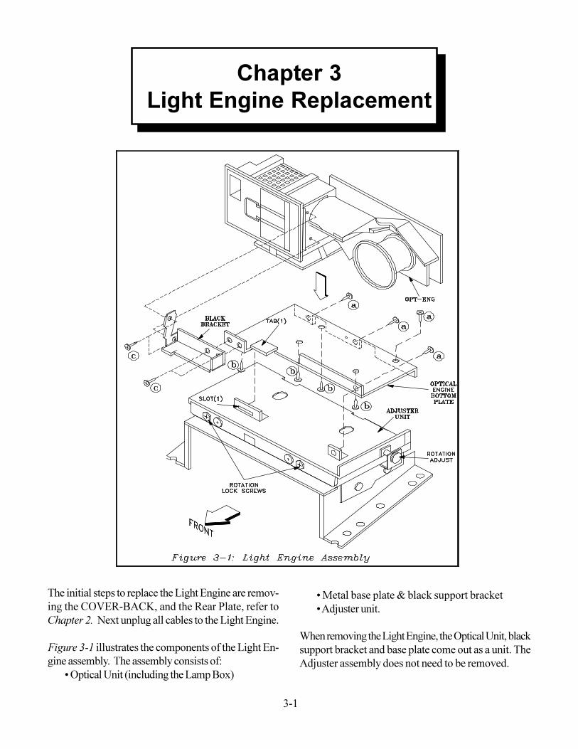
The initial steps to replace the Light Engine are remov-ing the COVER-BACK, and the Rear Plate, refer toChapter 2. Next unplug all cables to the Light Engine.Figure 3-1 illustrates the components of the Light En-gine assembly. The assembly consists of:
� Optical Unit (including the Lamp Box)
� Metal base plate & black support bracket� Adjuster unit.
When removing the Light Engine, the Optical Unit, blacksupport bracket and base plate come out as a unit. TheAdjuster assembly does not need to be removed.
Chapter 3Light Engine Replacement
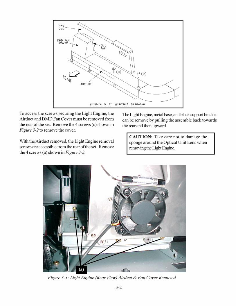
3-2Figure 3-3: Light Engine (Rear View) Airduct & Fan Cover Removed
To access the screws securing the Light Engine, theAirduct and DMD Fan Cover must be removed fromthe rear of the set. Remove the 4 screws (c) shown inFigure 3-2 to remove the cover.With the Airduct removed, the Light Engine removalscrews are accessible from the rear of the set. Removethe 4 screws (a) shown in Figure 3-3.
The Light Engine, metal base, and black support bracketcan be remove by pulling the assemble back towardsthe rear and then upward.
CAUTION: Take care not to damage thesponge around the Optical Unit Lens whenremoving the Light Engine.
(a)
3-3
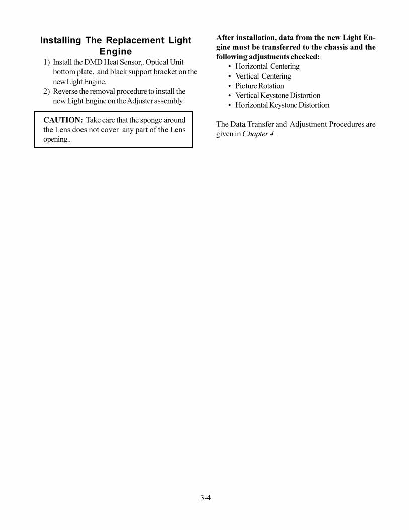
Bottom Plate
(b)
Figure 3-5: Bottom Plate Removal
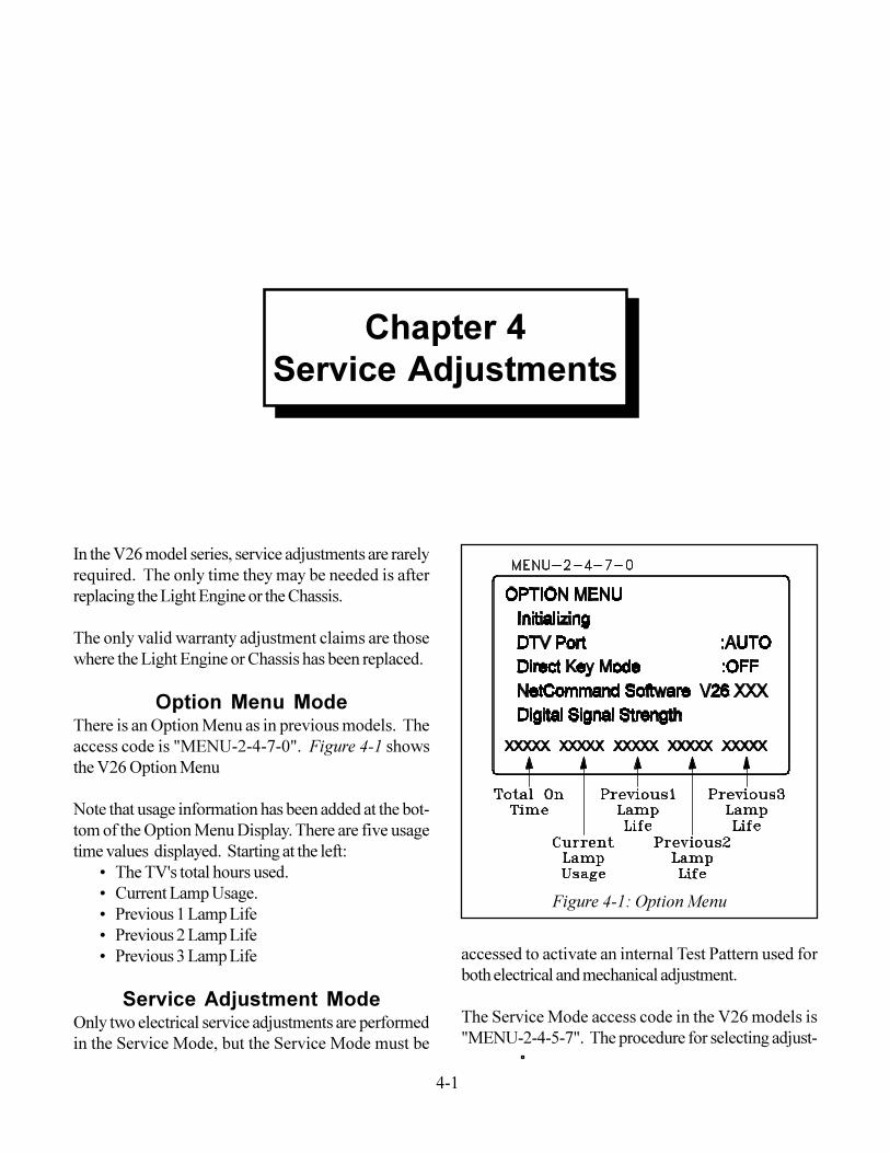
(c)Black Support
BracketFigure 3-6: Black support Bracket Removal
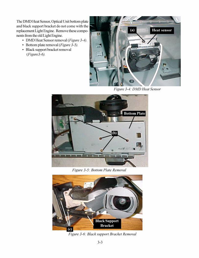
The DMD Heat Sensor, Optical Unit bottom plateand black support bracket do not come with thereplacement Light Engine. Remove these compo-nents from the old Light Engine.
� DMD Heat Sensor removal (Figure 3-4).� Bottom plate removal (Figure 3-5).� Black support bracket removal
(Figure3-6).
(a) Heat sensor
Figure 3-4: DMD Heat Sensor
3-4
Installing The Replacement LightEngine
1) Install the DMD Heat Sensor,. Optical Unitbottom plate, and black support bracket on thenew Light Engine.
2) Reverse the removal procedure to install thenew Light Engine on the Adjuster assembly.
CAUTION: Take care that the sponge aroundthe Lens does not cover any part of the Lensopening..
After installation, data from the new Light En-gine must be transferred to the chassis and thefollowing adjustments checked:
� Horizontal Centering� Vertical Centering� Picture Rotation� Vertical Keystone Distortion� Horizontal Keystone Distortion
The Data Transfer and Adjustment Procedures aregiven in Chapter 4.
4-1
In the V26 model series, service adjustments are rarelyrequired. The only time they may be needed is afterreplacing the Light Engine or the Chassis.The only valid warranty adjustment claims are thosewhere the Light Engine or Chassis has been replaced.
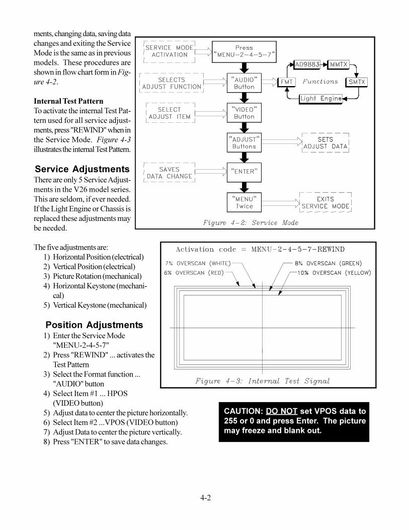
Option Menu ModeThere is an Option Menu as in previous models. Theaccess code is "MENU-2-4-7-0". Figure 4-1 showsthe V26 Option MenuNote that usage information has been added at the bot-tom of the Option Menu Display. There are five usagetime values displayed. Starting at the left:
� The TV's total hours used.� Current Lamp Usage.� Previous 1 Lamp Life� Previous 2 Lamp Life� Previous 3 Lamp Life
Service Adjustment ModeOnly two electrical service adjustments are performedin the Service Mode, but the Service Mode must be
Figure 4-1: Option Menu
accessed to activate an internal Test Pattern used forboth electrical and mechanical adjustment.The Service Mode access code in the V26 models is"MENU-2-4-5-7". The procedure for selecting adjust-
Chapter 4Service Adjustments
4-2
ments, changing data, saving datachanges and exiting the ServiceMode is the same as in previousmodels. These procedures areshown in flow chart form in Fig-ure 4-2.Internal Test PatternTo activate the internal Test Pat-tern used for all service adjust-ments, press "REWIND" when inthe Service Mode. Figure 4-3illustrates the internal Test Pattern.Service AdjustmentsThere are only 5 Service Adjust-ments in the V26 model series.This are seldom, if ever needed.If the Light Engine or Chassis isreplaced these adjustments maybe needed.The five adjustments are:
1) Horizontal Position (electrical)2) Vertical Position (electrical)3) Picture Rotation (mechanical)4) Horizontal Keystone (mechani-
cal)5) Vertical Keystone (mechanical)Position Adjustments
1) Enter the Service Mode"MENU-2-4-5-7"
2) Press "REWIND" ... activates theTest Pattern
3) Select the Format function ..."AUDIO" button
4) Select Item #1 ... HPOS(VIDEO button)
5) Adjust data to center the picture horizontally.6) Select Item #2 ...VPOS (VIDEO button)7) Adjust Data to center the picture vertically.8) Press "ENTER" to save data changes.ON: DO NOT set VPOS data to 255 oress
CAUTION: DO NOT set VPOS data to255 or 0 and press Enter. The picturemay freeze and blank out.
4-3
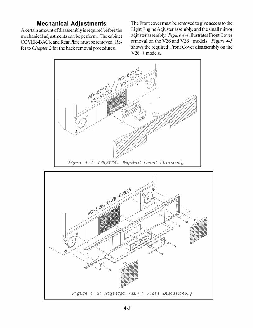
Mechanical AdjustmentsA certain amount of disassembly is required before themechanical adjustments can be perform. The cabinetCOVER-BACK and Rear Plate must be removed. Re-fer to Chapter 2 for the back removal procedures.
The Front cover must be removed to give access to theLight Engine Adjuster assembly, and the small mirroradjuster assembly. Figure 4-4 illustrates Front Coverremoval on the V26 and V26+ models. Figure 4-5shows the required Front Cover disassembly on theV26++ models.
4-4
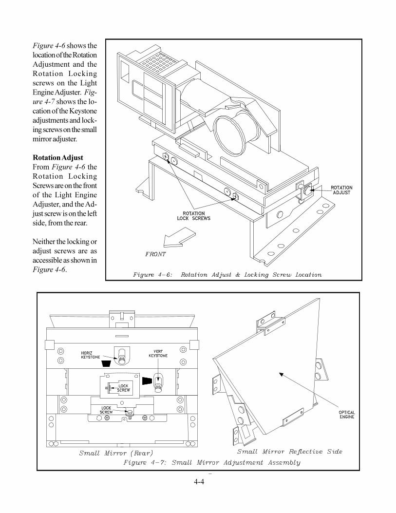
Figure 4-6 shows thelocation of the RotationAdjustment and theRotation Lockingscrews on the LightEngine Adjuster. Fig-ure 4-7 shows the lo-cation of the Keystoneadjustments and lock-ing screws on the smallmirror adjuster.Rotation AdjustFrom Figure 4-6 theRotation LockingScrews are on the frontof the Light EngineAdjuster, and the Ad-just screw is on the leftside, from the rear.Neither the locking oradjust screws are asaccessible as shown inFigure 4-6.
4-5
For all mechanical adjustments:� Locking screws are brass.� Adjustment screw are black. (A 4mm Allen
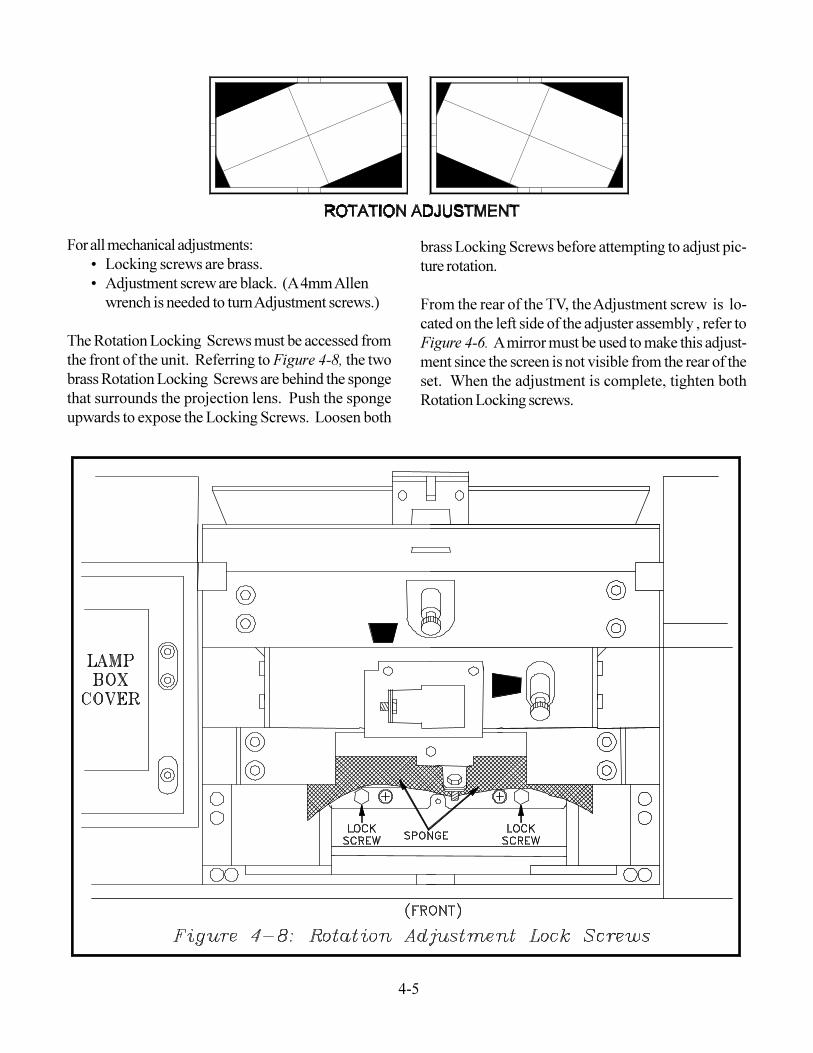
wrench is needed to turn Adjustment screws.)The Rotation Locking Screws must be accessed fromthe front of the unit. Referring to Figure 4-8, the twobrass Rotation Locking Screws are behind the spongethat surrounds the projection lens. Push the spongeupwards to expose the Locking Screws. Loosen both
brass Locking Screws before attempting to adjust pic-ture rotation.From the rear of the TV, the Adjustment screw is lo-cated on the left side of the adjuster assembly , refer toFigure 4-6. A mirror must be used to make this adjust-ment since the screen is not visible from the rear of theset. When the adjustment is complete, tighten bothRotation Locking screws.
4-6
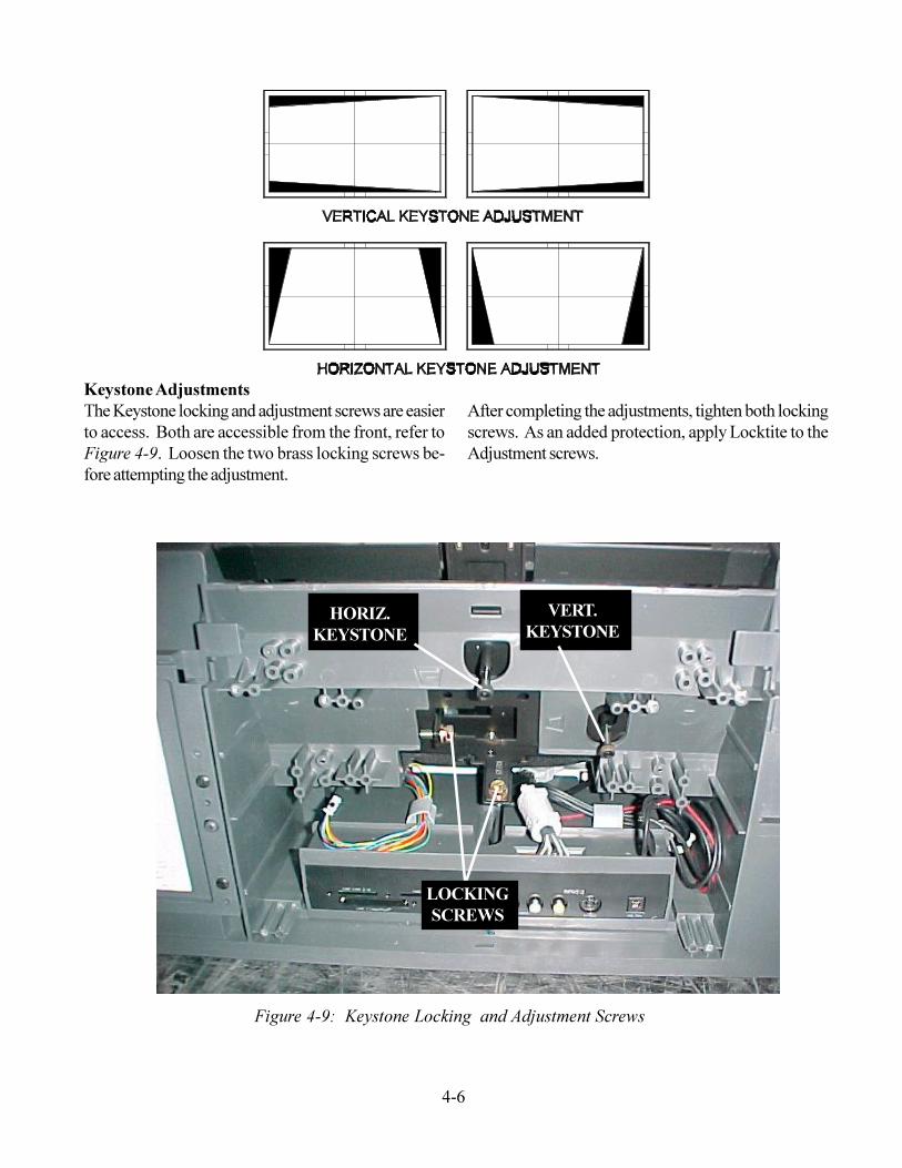
Keystone AdjustmentsThe Keystone locking and adjustment screws are easierto access. Both are accessible from the front, refer toFigure 4-9. Loosen the two brass locking screws be-fore attempting the adjustment.
LOCKINGSCREWS
HORIZ.KEYSTONE
VERT.KEYSTONE
Figure 4-9: Keystone Locking and Adjustment Screws
After completing the adjustments, tighten both lockingscrews. As an added protection, apply Locktite to theAdjustment screws.
4-7
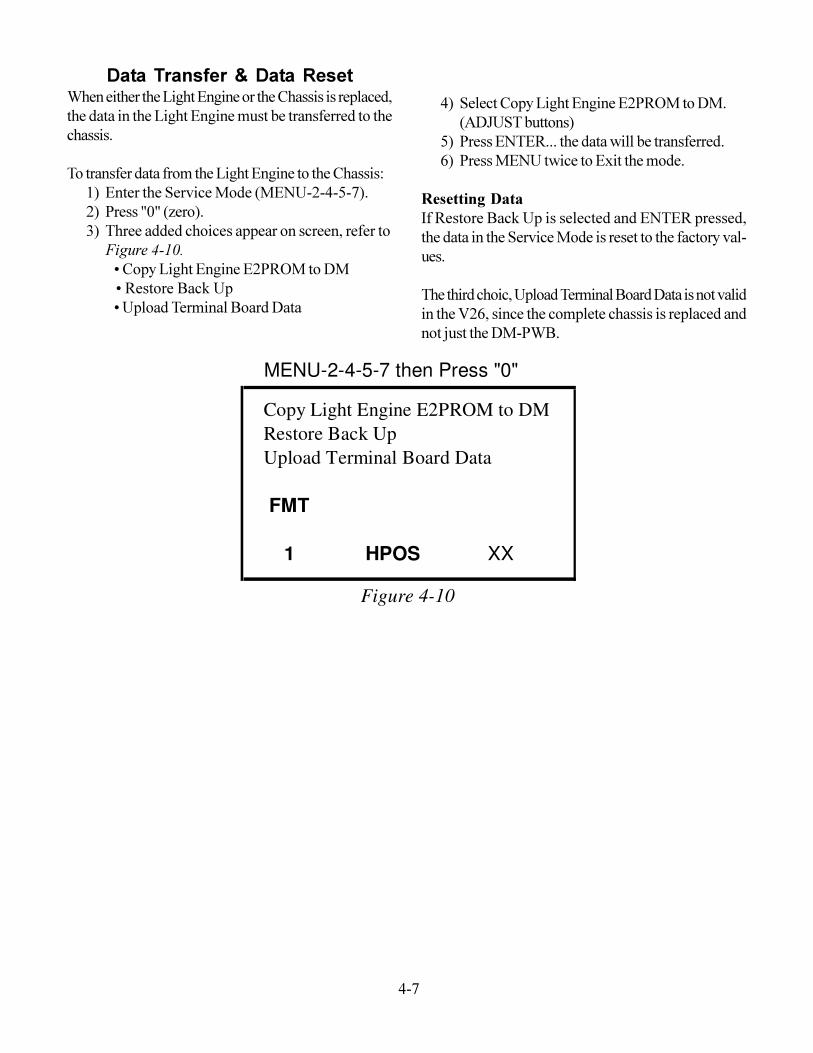
Data Transfer & Data ResetWhen either the Light Engine or the Chassis is replaced,the data in the Light Engine must be transferred to thechassis.To transfer data from the Light Engine to the Chassis:
1) Enter the Service Mode (MENU-2-4-5-7).2) Press "0" (zero).3) Three added choices appear on screen, refer to
Figure 4-10. � Copy Light Engine E2PROM to DM � Restore Back Up � Upload Terminal Board Data
4) Select Copy Light Engine E2PROM to DM.(ADJUST buttons)
5) Press ENTER... the data will be transferred.6) Press MENU twice to Exit the mode.
Resetting DataIf Restore Back Up is selected and ENTER pressed,the data in the Service Mode is reset to the factory val-ues.The third choic, Upload Terminal Board Data is not validin the V26, since the complete chassis is replaced andnot just the DM-PWB.
MENU-2-4-5-7 then Press "0"
Copy Light Engine E2PROM to DMRestore Back UpUpload Terminal Board Data
FMT
1 HPOS XX
Figure 4-10

4-8
5-1
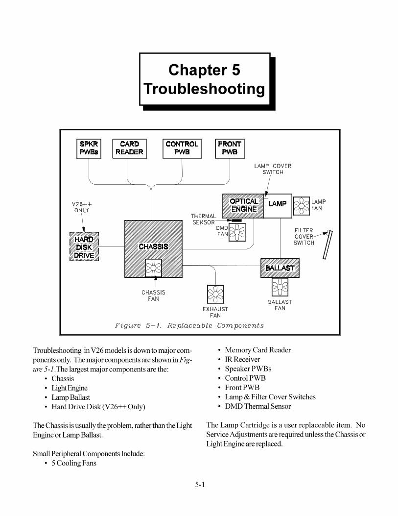
Troubleshooting in V26 models is down to major com-ponents only. The major components are shown in Fig-ure 5-1.The largest major components are the:
� Chassis� Light Engine� Lamp Ballast� Hard Drive Disk (V26++ Only)
The Chassis is usually the problem, rather than the LightEngine or Lamp Ballast.Small Peripheral Components Include:
� 5 Cooling Fans
� Memory Card Reader� IR Receiver� Speaker PWBs� Control PWB� Front PWB� Lamp & Filter Cover Switches� DMD Thermal Sensor
The Lamp Cartridge is a user replaceable item. NoService Adjustments are required unless the Chassis orLight Engine are replaced.
Chapter 5Troubleshooting
5-2
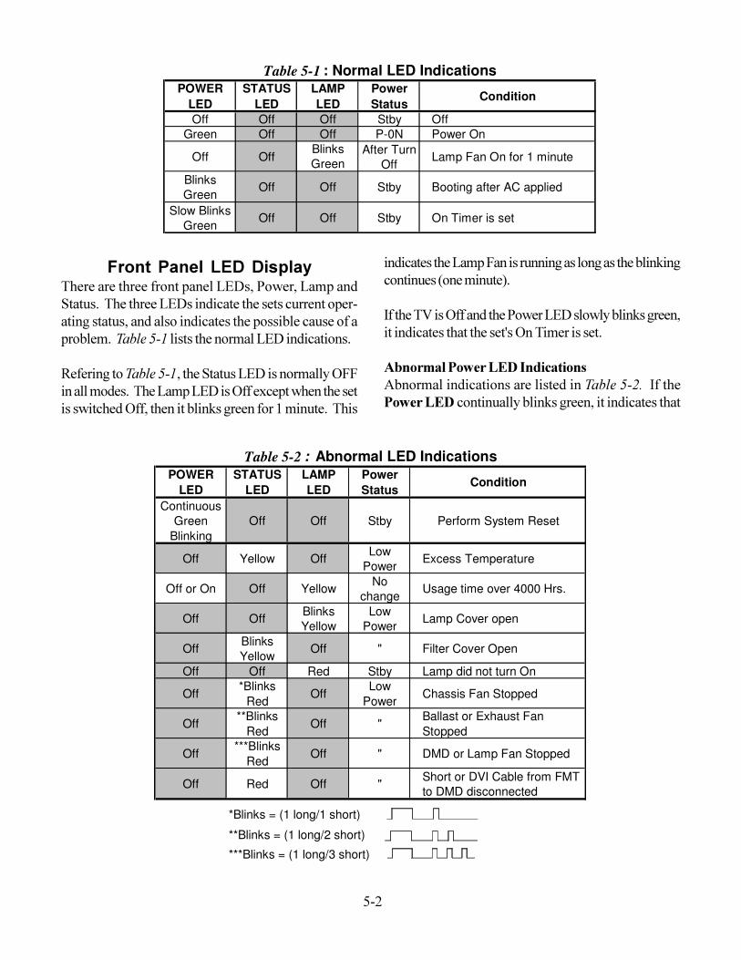
Front Panel LED DisplayThere are three front panel LEDs, Power, Lamp andStatus. The three LEDs indicate the sets current oper-ating status, and also indicates the possible cause of aproblem. Table 5-1 lists the normal LED indications.Refering to Table 5-1, the Status LED is normally OFFin all modes. The Lamp LED is Off except when the setis switched Off, then it blinks green for 1 minute. This
POWER LED
STATUS LED
LAMP LED
Power Status
Condition
Off Off Off Stby OffGreen Off Off P-0N Power On
Off OffBlinks Green
After Turn Off
Lamp Fan On for 1 minute
Blinks Green
Off Off Stby Booting after AC applied
Slow Blinks Green
Off Off Stby On Timer is set
Table 5-1 : Normal LED Indications
POWER LED
STATUS LED
LAMP LED
Power Status
Condition
Continuous Green
BlinkingOff Off Stby Perform System Reset
Off Yellow Off Low Power
Excess Temperature
Off or On Off Yellow No change
Usage time over 4000 Hrs.
Off Off Blinks Yellow
Low Power
Lamp Cover open
Off Blinks Yellow
Off " Filter Cover Open
Off Off Red Stby Lamp did not turn On
Off*Blinks
RedOff
Low Power
Chassis Fan Stopped
Off**Blinks
RedOff "
Ballast or Exhaust Fan Stopped
Off***Blinks
RedOff " DMD or Lamp Fan Stopped
Off Red Off " Short or DVI Cable from FMT to DMD disconnected
*Blinks = (1 long/1 short)
**Blinks = (1 long/2 short)
***Blinks = (1 long/3 short)
Table 5-2 : Abnormal LED Indications
indicates the Lamp Fan is running as long as the blinkingcontinues (one minute).If the TV is Off and the Power LED slowly blinks green,it indicates that the set's On Timer is set.Abnormal Power LED IndicationsAbnormal indications are listed in Table 5-2. If thePower LED continually blinks green, it indicates that
5-3
the DM has not booted up. Press the front panel Resetbutton, or unplug AC and then plug the AC back in.Abnormal Status LED IndicationsIf the Status LED is constant yellow, it indicates excesstemperature. Check the Air Filter and clean if neces-sary.If the Status LED blinks yellow, check that the Filtercover is installed properly.If the Staus LED blinks red, note the code.
� 1 long...1 short = Chassis Fan stopped� 1 long...2 short = Ballast or Exhaust Fan
stopped.� 1 long...3 short = DMD or Lamp Fan stopped.
If the Status LED is constant red, there is a circuit fail-ure (short), or the DVI cable to the Light Engine is dis-connect.Abnormal Lamp LED Indications
� Constant yellow ... current Lamp usage is over4000 hours.
� Blinks yellow ...Lamp Cover is open.� Contant red ... Lamp failed to turn On (refer the
the Lamp Troubleshooting Procedure)
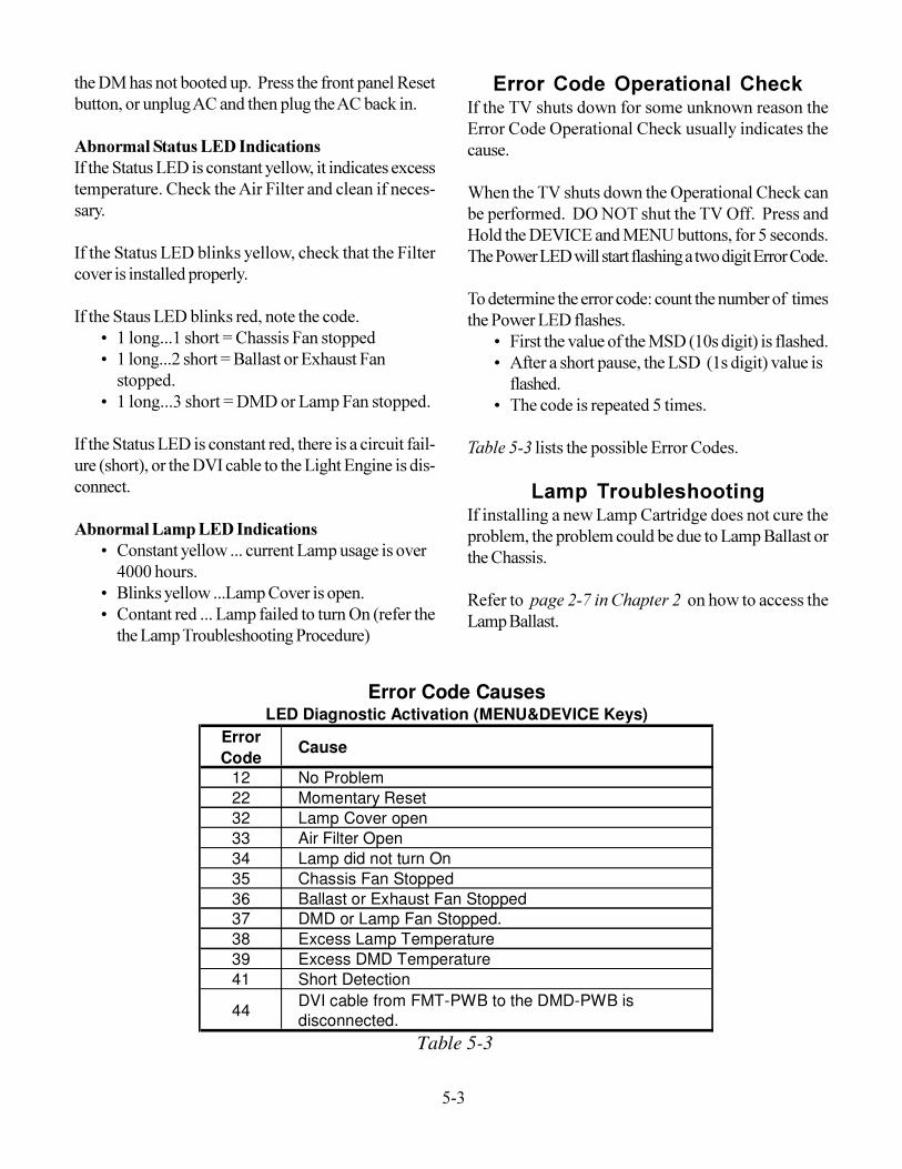
Error Code Operational CheckIf the TV shuts down for some unknown reason theError Code Operational Check usually indicates thecause.When the TV shuts down the Operational Check canbe performed. DO NOT shut the TV Off. Press andHold the DEVICE and MENU buttons, for 5 seconds.The Power LED will start flashing a two digit Error Code.To determine the error code: count the number of timesthe Power LED flashes.
� First the value of the MSD (10s digit) is flashed.� After a short pause, the LSD (1s digit) value is
flashed.� The code is repeated 5 times.
Table 5-3 lists the possible Error Codes.Lamp Troubleshooting
If installing a new Lamp Cartridge does not cure theproblem, the problem could be due to Lamp Ballast orthe Chassis.Refer to page 2-7 in Chapter 2 on how to access theLamp Ballast.
Error Code
Cause
12 No Problem22 Momentary Reset32 Lamp Cover open33 Air Filter Open34 Lamp did not turn On35 Chassis Fan Stopped36 Ballast or Exhaust Fan Stopped37 DMD or Lamp Fan Stopped.38 Excess Lamp Temperature39 Excess DMD Temperature41 Short Detection
44 DVI cable from FMT-PWB to the DMD-PWB is disconnected.
Error Code CausesLED Diagnostic Activation (MENU&DEVICE Keys)
Table 5-3
5-4
TP6VS
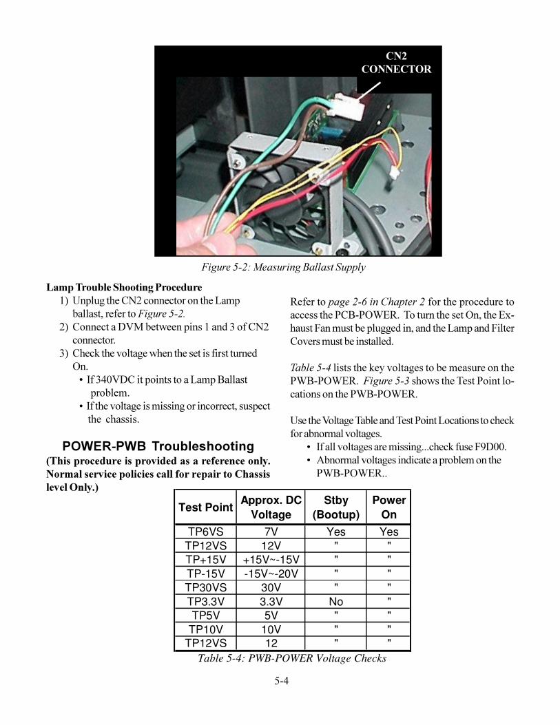
Figure 5-2: Measuring Ballast Supply
CN2CONNECTOR
Lamp Trouble Shooting Procedure1) Unplug the CN2 connector on the Lamp
ballast, refer to Figure 5-2.2) Connect a DVM between pins 1 and 3 of CN2
connector.3) Check the voltage when the set is first turned
On.� If 340VDC it points to a Lamp Ballast problem.� If the voltage is missing or incorrect, suspect the chassis.
POWER-PWB Troubleshooting(This procedure is provided as a reference only.Normal service policies call for repair to Chassislevel Only.)
Test PointApprox. DC
VoltageStby
(Bootup)Power
OnTP6VS 7V Yes YesTP12VS 12V " "TP+15V +15V~-15V " "TP-15V -15V~-20V " "TP30VS 30V " "TP3.3V 3.3V No "TP5V 5V " "
TP10V 10V " "TP12VS 12 " "
Table 5-4: PWB-POWER Voltage Checks
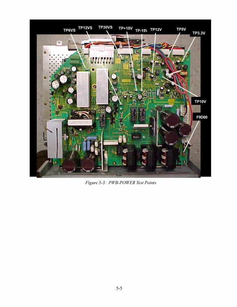
Refer to page 2-6 in Chapter 2 for the procedure toaccess the PCB-POWER. To turn the set On, the Ex-haust Fan must be plugged in, and the Lamp and FilterCovers must be installed.Table 5-4 lists the key voltages to be measure on thePWB-POWER. Figure 5-3 shows the Test Point lo-cations on the PWB-POWER.Use the Voltage Table and Test Point Locations to checkfor abnormal voltages.
� If all voltages are missing...check fuse F9D00.� Abnormal voltages indicate a problem on the
PWB-POWER..
5-5
TP6VS TP12VS TP30VS
F9D00
TP+15V TP-15V TP12V TP5V TP3.3V
TP10V
Figure 5-3: PWB-POWER Test Points

5-6
6-1
Chapter 6Block Diagrams
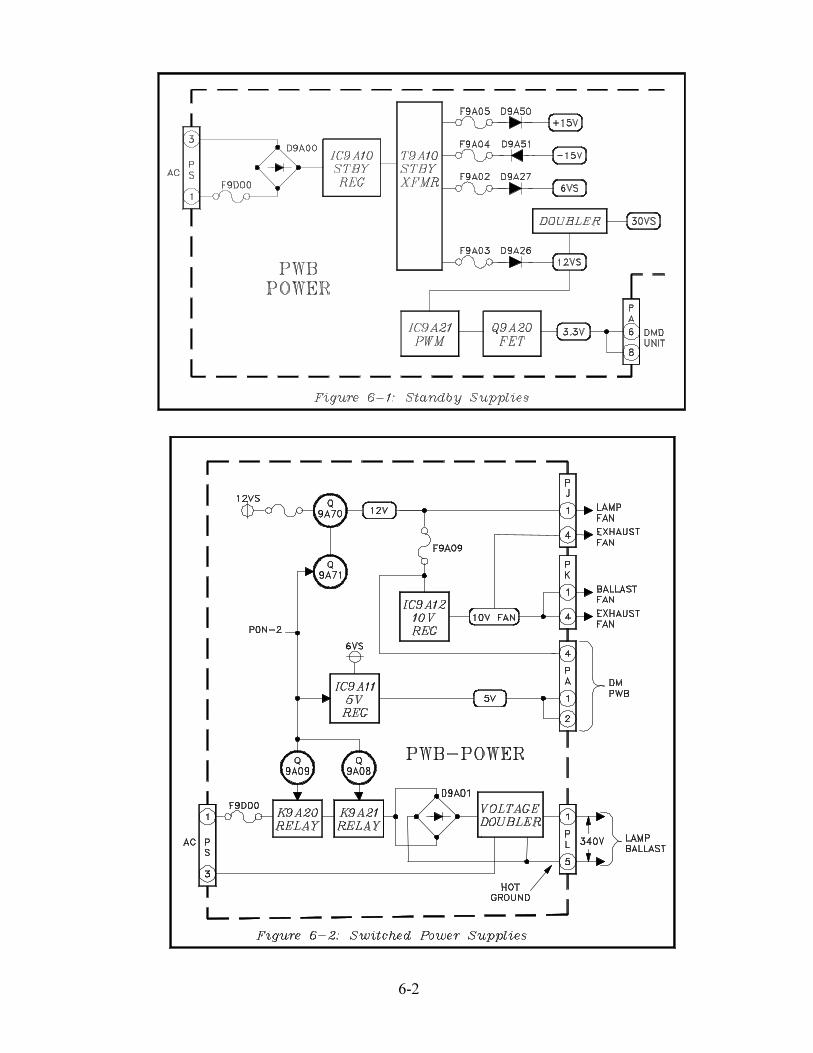
POWER SUPPLY� Standby Power Supplies� Switched Power Supplies
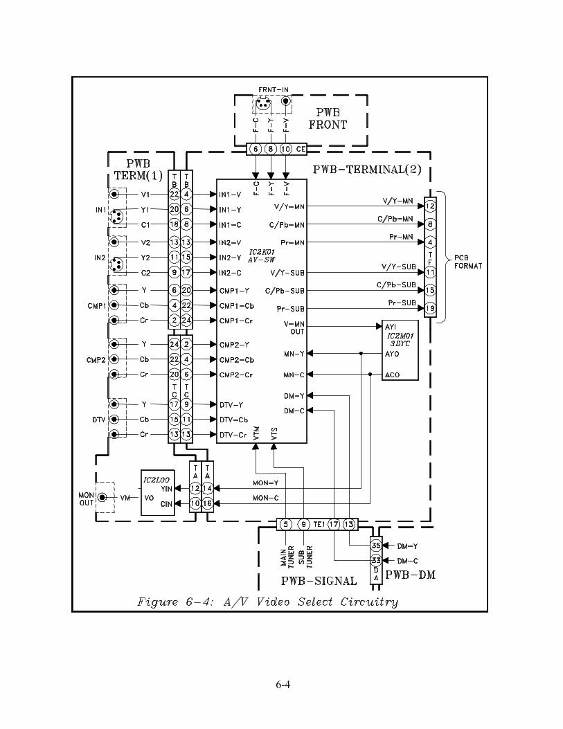
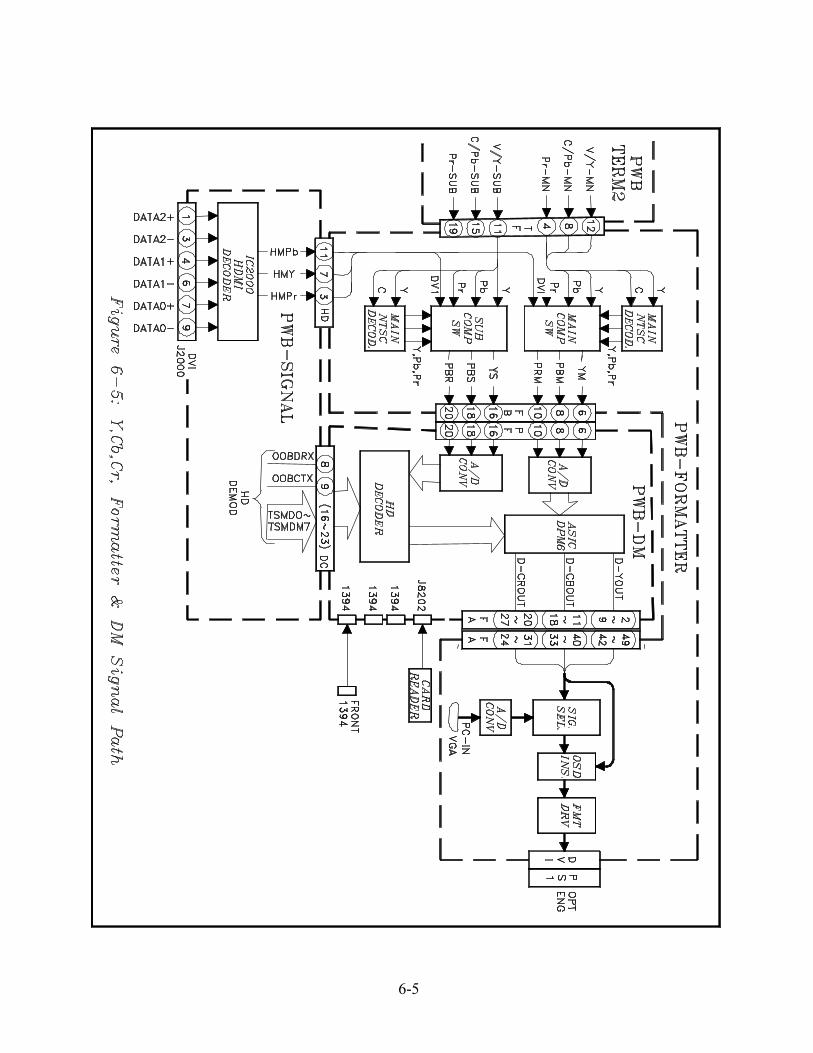
VIDEO SIGNAL PATH� Tuner Circuitry� A/V Video Select Circuitry� Y,Cb,Cr Signal Path
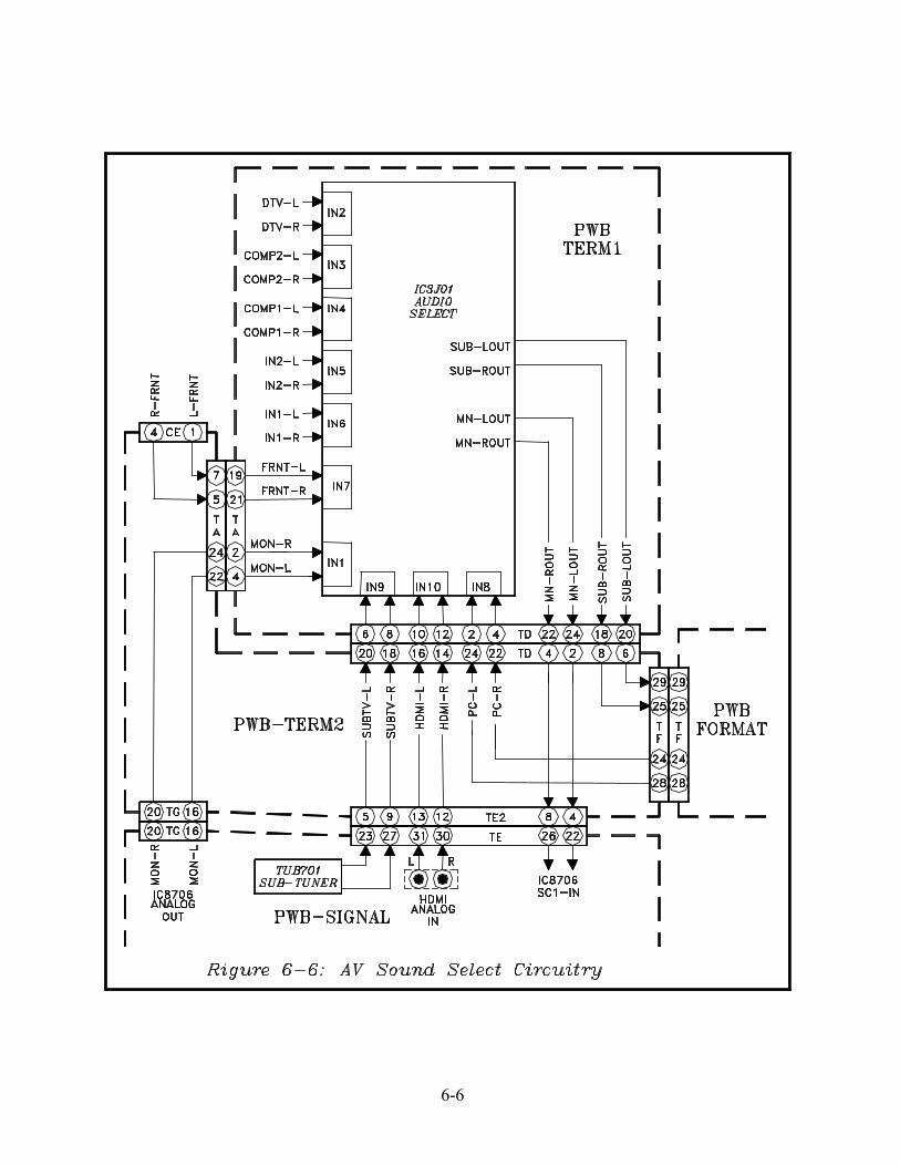
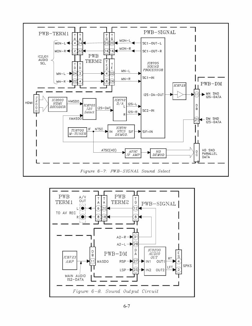
SOUND CIRCUITRY� A/V Sound Select Circuitry� PWB-SIGNAL Sound Select Circuitry� Sound Output Circuitry
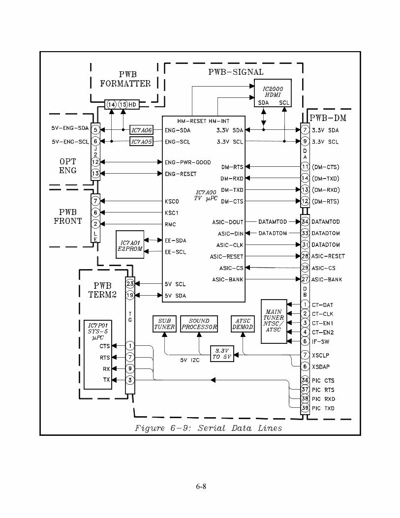
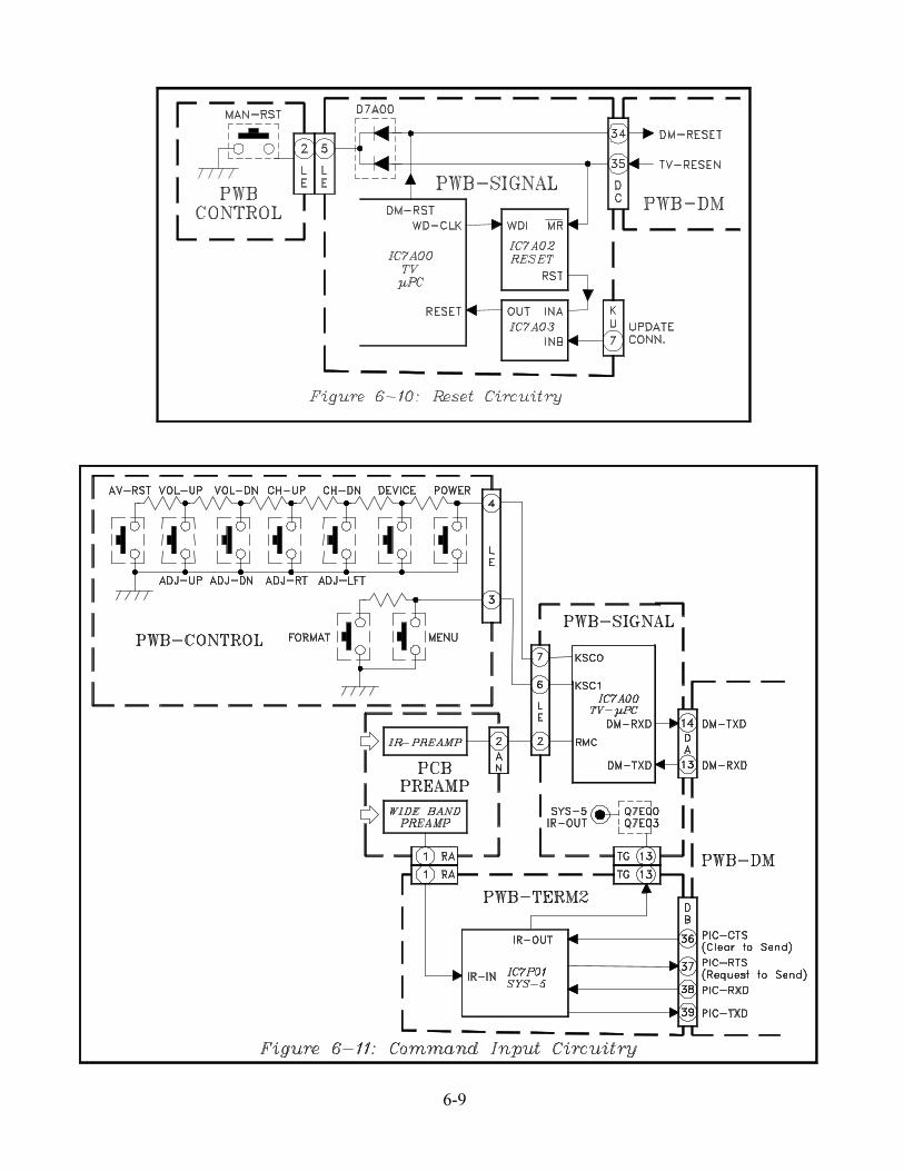
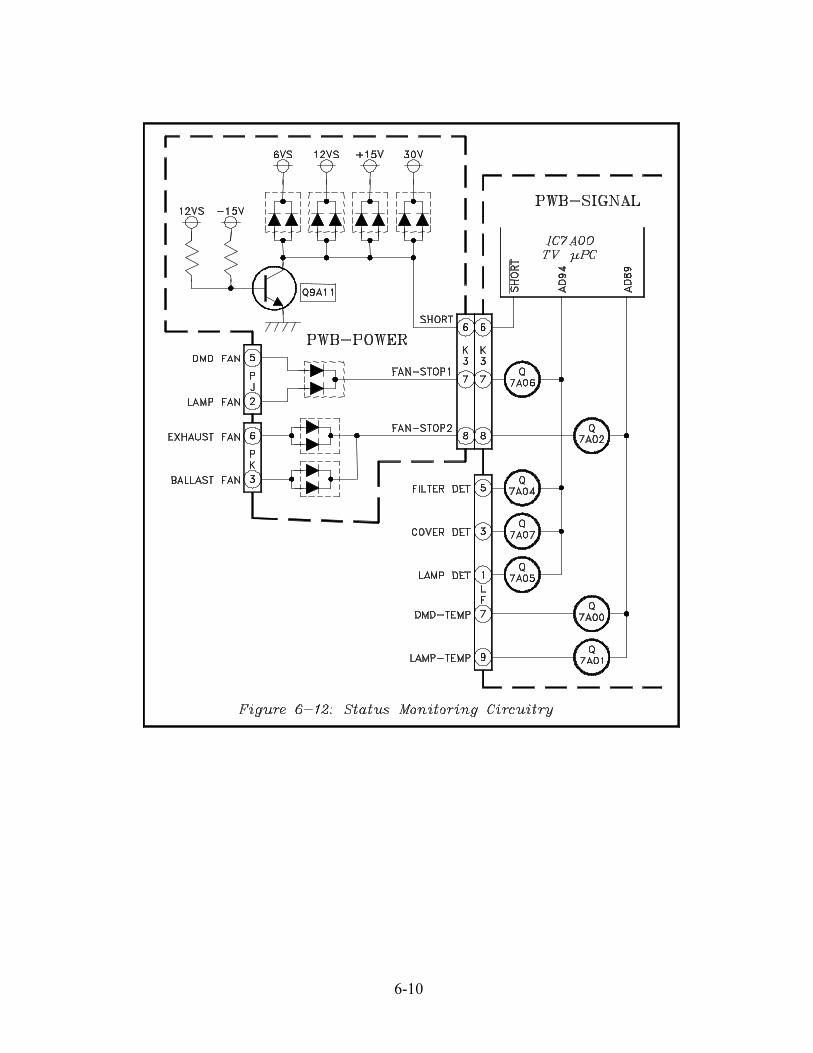
CONTROL CIRCUITRY� Serial Control Lines� Reset Circuitry� Command Input Circuitry� Status Monitoring Circuitry
The Block Diagrams in this chapter are not detailed, but serve to familiarize technicians with the circuitry in thevarious sections on the TV, and to give them some feeling for the the signal path. The diagrams include:
6-2
6-3
6-4
6-5
6-6
6-7
6-8
6-9
6-10


![Samsung l62a Chassis St61l2hdx Projection [ET]](https://img.pdfslide.us/doc/110x75/549e082eac79591a768b462e/samsung-l62a-chassis-st61l2hdx-projection-et.jpg)

![Drums Etc [v26-n3] Summer 2014](https://img.pdfslide.us/doc/110x75/568c53d91a28ab4916bc7505/drums-etc-v26-n3-summer-2014.jpg)


![Drums Etc [v26-n1] Winter 2014](https://img.pdfslide.us/doc/110x75/568c4dc41a28ab4916a53f7a/drums-etc-v26-n1-winter-2014.jpg)