Embed Size (px)
Citation preview

Machine Automation Controller
NX-series
Digital I/O Units
Digital I/O Units
User’s Manual
W521-E1-07
NX-IDNX-IANX-OCNX-ODNX-MD

All rights reserved. No part of this publication may be reproduced, stored in a retrieval system, or transmitted, in any form, or by any means, mechanical, electronic, photocopying, recording, or otherwise, without the prior written permission of OMRON.
No patent liability is assumed with respect to the use of the information contained herein. Moreover, because OMRON is constantly striving to improve its high-quality products, the information contained in this manual is subject to change without notice. Every precaution has been taken in the preparation of this manual. Neverthe-less, OMRON assumes no responsibility for errors or omissions. Neither is any liability assumed for damages resulting from the use of the information contained in this publication.
• Sysmac and SYSMAC are trademarks or registered trademarks of OMRON Corporation in Japan and other countries for OMRON factory automation products.
• Microsoft, Windows, Windows Vista, Excel, and Visual Basic are either registered trademarks or trademarks of Microsoft Corporation in the United States and other countries.
• EtherCAT® is registered trademark and patented technology, licensed by Beckhoff Automation GmbH, Germany.
• Safety over EtherCAT® is registered trademark and patented technology, licensed by Beckhoff Automation GmbH, Germany.
• ODVA, CIP, CompoNet, DeviceNet, and EtherNet/IP are trademarks of ODVA.
• The SD and SDHC logos are trademarks of SD-3C, LLC.
Other company names and product names in this document are the trademarks or registered trademarks of their respective companies.
Trademarks
Copyrights
NOTE
Microsoft product screen shots reprinted with permission from Microsoft Corporation.

1
Introduction
NX-series Digital I/O Unit User’s Manual (W521)
Introduction
Thank you for purchasing an NX-series Digital I/O Unit.
This manual contains information that is necessary to use the NX-series Digital I/O Unit. Please read this manual and make sure you understand the functionality and performance of the NX-series Digital I/O Unit before you attempt to use it in a control system.
Keep this manual in a safe place where it will be available for reference during operation.
This manual is intended for the following personnel, who must also have knowledge of electrical sys-tems (an electrical engineer or the equivalent).• Personnel in charge of introducing FA systems.• Personnel in charge of designing FA systems.• Personnel in charge of installing and maintaining FA systems.• Personnel in charge of managing FA systems and facilities.
For programming, this manual is intended for personnel who understand the programming language specifications in international standard IEC 61131-3 or Japanese standard JIS B 3503.
This manual covers the following product.• NX-series Digital I/O Unit
NX-ID /IA /OD/OC/MD
Intended Audience
Applicable Products

CONTENTS
2 NX-series Digital I/O Unit User’s Manual (W521)
CONTENTS
Introduction ..............................................................................................................1Intended Audience....................................................................................................................................... 1Applicable Products ..................................................................................................................................... 1
Relevant Manuals .....................................................................................................7
Manual Structure ......................................................................................................8Page Structure and Icons ............................................................................................................................ 8Special Information ...................................................................................................................................... 9Precaution on Terminology ........................................................................................................................ 10
Terms and Conditions Agreement ........................................................................ 11Warranty, Limitations of Liability ................................................................................................................ 11Application Considerations ........................................................................................................................ 12Disclaimers ................................................................................................................................................ 12
Safety Precautions .................................................................................................13Definition of Precautionary Information...................................................................................................... 13Symbols ..................................................................................................................................................... 13Warnings.................................................................................................................................................... 14Cautions..................................................................................................................................................... 15
Precautions for Safe Use.......................................................................................17
Precautions for Correct Use..................................................................................22
Regulations and Standards ...................................................................................23Conformance to EU Directives .................................................................................................................. 23Conformance to UL and CSA Standards ................................................................................................... 24Conformance to Shipbuilding Standards ................................................................................................... 24Conformance to KC Standards .................................................................................................................. 24Software Licenses and Copyrights ............................................................................................................ 24
Unit Versions ..........................................................................................................25Unit Versions.............................................................................................................................................. 25Unit Versions and Support Software Versions ........................................................................................... 26
Related Manuals .....................................................................................................27
Terminology ............................................................................................................30
Revision History .....................................................................................................32
Sections in this Manual .........................................................................................33
Section 1 Features and System Configuration
1-1 Features and Types of Digital I/O Units ............................................................................... 1-21-1-1 Digital I/O Unit Features.............................................................................................................. 1-21-1-2 Digital I/O Unit Types .................................................................................................................. 1-3
1-2 System Configuration ........................................................................................................... 1-41-2-1 System Configuration in the Case of a CPU Unit........................................................................ 1-41-2-2 System Configuration of Slave Terminals ...................................................................................1-5
3
CONTENTS
NX-series Digital I/O Unit User’s Manual (W521)
1-3 Model List............................................................................................................................... 1-71-3-1 Model Notation............................................................................................................................ 1-71-3-2 Digital Input Units...................................................................................................................... 1-101-3-3 Digital Output Units................................................................................................................... 1-121-3-4 Digital Mixed I/O Units .............................................................................................................. 1-15
1-4 List of Functions.................................................................................................................. 1-161-4-1 Digital Input Units...................................................................................................................... 1-161-4-2 Digital Output Units................................................................................................................... 1-171-4-3 Digital Mixed I/O Units .............................................................................................................. 1-18
1-5 Support Software................................................................................................................. 1-19
Section 2 Specifications
2-1 General Specifications.......................................................................................................... 2-22-2 Individual Specifications ...................................................................................................... 2-3
Section 3 Part Names and Functions
3-1 Part Names............................................................................................................................. 3-23-1-1 Screwless Clamping Terminal Block Type .................................................................................. 3-23-1-2 M3 Screw Terminal Block Type................................................................................................... 3-73-1-3 Connector Types......................................................................................................................... 3-8
3-2 Indicators ............................................................................................................................. 3-133-2-1 TS Indicator .............................................................................................................................. 3-153-2-2 IN/OUT Indicator....................................................................................................................... 3-16
Section 4 Installation and Wiring
4-1 Installing NX Units ................................................................................................................ 4-24-1-1 Installing NX Units ...................................................................................................................... 4-24-1-2 Attaching Markers....................................................................................................................... 4-44-1-3 Removing NX Units .................................................................................................................... 4-64-1-4 Installation Orientation ................................................................................................................ 4-7
4-2 Power Supply Types and Wiring .......................................................................................... 4-94-2-1 Applications of I/O Power Supply and Supply Methods.............................................................. 4-94-2-2 Calculating the Total Current Consumption from I/O Power Supply ..........................................4-11
4-3 Wiring the Terminals ........................................................................................................... 4-124-3-1 Wiring to the Screwless Clamping Terminal Block.................................................................... 4-124-3-2 Wiring to M3 Screw Terminal Block .......................................................................................... 4-314-3-3 Wiring to MIL/Fujitsu Connectors.............................................................................................. 4-354-3-4 Checking the Wiring.................................................................................................................. 4-39
4-4 Wiring Examples.................................................................................................................. 4-404-4-1 Wiring the Input Units ............................................................................................................... 4-404-4-2 Precautions when Wiring to the Output Units ........................................................................... 4-52
Section 5 I/O Refreshing
5-1 I/O Refreshing ........................................................................................................................ 5-25-1-1 I/O Refreshing from CPU Units to NX Units ............................................................................... 5-25-1-2 I/O Refreshing from CPU Units or Industrial PCs to Slave Terminal .......................................... 5-3
5-2 I/O Refreshing Methods ........................................................................................................ 5-55-2-1 Types of I/O Refreshing Methods ............................................................................................... 5-5

CONTENTS
4 NX-series Digital I/O Unit User’s Manual (W521)
5-2-2 Setting the I/O Refreshing Methods............................................................................................ 5-75-2-3 Selecting NX Units ...................................................................................................................... 5-85-2-4 Free-Run Refreshing................................................................................................................... 5-85-2-5 Synchronous Input Refreshing.................................................................................................. 5-125-2-6 Synchronous Output Refreshing............................................................................................... 5-165-2-7 Time Stamp Refreshing............................................................................................................. 5-195-2-8 Input Refreshing with Input Changed Time............................................................................... 5-205-2-9 Output Refreshing with Specified Time Stamp.......................................................................... 5-275-2-10 An Example of Turning ON Outputs at Specific Times After the Sensor Inputs Change .......... 5-33
Section 6 Digital Input Units
6-1 Types of Digital Input Units................................................................................................... 6-26-2 Specifications of I/O Data ..................................................................................................... 6-4
6-2-1 Allocable I/O Data ....................................................................................................................... 6-4
6-3 List of Settings....................................................................................................................... 6-76-4 Function ............................................................................................................................... 6-13
6-4-1 List of Digital Input Unit Functions............................................................................................. 6-136-4-2 Input Filter ................................................................................................................................. 6-14
Section 7 Digital Output Units
7-1 Types of Digital Output Units................................................................................................ 7-27-2 Specifications of I/O Data ..................................................................................................... 7-5
7-2-1 Allocable I/O Data ....................................................................................................................... 7-5
7-3 List of Settings....................................................................................................................... 7-97-4 Function ............................................................................................................................... 7-12
7-4-1 List of Digital Output Unit Functions.......................................................................................... 7-127-4-2 Load Rejection Output Setting .................................................................................................. 7-137-4-3 Load Short-circuit Protection..................................................................................................... 7-17
7-5 Push-pull Output ................................................................................................................. 7-197-6 Precautions when Using the Relay Output Units ............................................................. 7-20
Section 8 Digital Mixed I/O Units
8-1 Types of Digital Mixed I/O Units ........................................................................................... 8-28-2 Specifications of I/O Data ..................................................................................................... 8-3
8-2-1 Allocable I/O Data ....................................................................................................................... 8-3
8-3 List of Settings....................................................................................................................... 8-58-3-1 Input Settings .............................................................................................................................. 8-58-3-2 Output Settings ........................................................................................................................... 8-6
8-4 Function ................................................................................................................................. 8-78-4-1 Input Functions............................................................................................................................ 8-78-4-2 Output Functions......................................................................................................................... 8-7
Section 9 Troubleshooting
9-1 How to Check for Errors ....................................................................................................... 9-29-2 Checking for Errors with the Indicators .............................................................................. 9-39-3 Checking for Errors and Troubleshooting on the Support Software................................ 9-5

5
CONTENTS
NX-series Digital I/O Unit User’s Manual (W521)
9-3-1 Checking for Errors from the Sysmac Studio.............................................................................. 9-59-3-2 Checking for Errors from Support Software Other Than the Sysmac Studio.............................. 9-69-3-3 Event Codes and Corrections for Errors..................................................................................... 9-79-3-4 Meaning of Error ....................................................................................................................... 9-10
9-4 Resetting Errors .................................................................................................................. 9-199-5 Troubles Specific To Each Type of NX Units..................................................................... 9-20
9-5-1 Digital Inputs ............................................................................................................................. 9-209-5-2 Digital Outputs .......................................................................................................................... 9-21
9-6 Troubleshooting Flowchart ................................................................................................ 9-22
Section 10 Inspection and Maintenance
10-1 Cleaning and Inspection ..................................................................................................... 10-210-1-1 Cleaning.................................................................................................................................... 10-210-1-2 Periodic Inspection ................................................................................................................... 10-2
10-2 Maintenance Procedures .................................................................................................... 10-5
Appendices
A-1 Data Sheet ..............................................................................................................................A-2A-1-1 Model List ................................................................................................................................... A-2A-1-2 Digital Input Units........................................................................................................................A-7A-1-3 Digital Output Units...................................................................................................................A-38A-1-4 Digital Mixed I/O Units ..............................................................................................................A-82
A-2 Dimensions ..........................................................................................................................A-96A-2-1 Screwless Clamping Terminal Block Type ................................................................................ A-96A-2-2 M3 Screw Terminal Block Type................................................................................................. A-98A-2-3 Connector Types....................................................................................................................... A-99
A-3 Connecting Connector-Terminal Block Conversion Units and I/O Relay Terminals...A-102A-3-1 Patterns for Combining Connector-Terminal Block Conversion Units
and I/O Relay Terminals .........................................................................................................A-102A-3-2 Combinations of Connections.................................................................................................A-104A-3-3 Connector-Terminal Block Conversion Unit Connection Diagrams ........................................ A-110A-3-4 Connection Diagrams for I/O Relay Terminals........................................................................ A-127
A-4 EMC Directive Measures for Relay Outputs....................................................................A-133A-5 List of NX Objects..............................................................................................................A-134
A-5-1 Format of Object Descriptions ................................................................................................A-134A-5-2 Digital Input Units....................................................................................................................A-135A-5-3 Digital Output Units.................................................................................................................A-143A-5-4 Digital Mixed I/O Units ............................................................................................................A-152
A-6 List of Screwless Clamping Terminal Block Models......................................................A-157A-6-1 Model Notation........................................................................................................................ A-157A-6-2 List of Terminal Block Models .................................................................................................A-157
A-7 Version Information with CPU Units ................................................................................A-158A-7-1 Relationship between Unit Versions of Units ..........................................................................A-158
A-8 Version Information with Communications Coupler Units ............................................A-160A-8-1 Connection to an EtherCAT Coupler Unit ............................................................................... A-160A-8-2 Connection to an EtherNet/IP Coupler Unit ............................................................................ A-162
A-9 Displaying the Edit Unit Operation Settings Tab Page ..................................................A-164A-9-1 Connection to the CPU Unit.................................................................................................... A-164A-9-2 Slave Terminal ........................................................................................................................ A-166

CONTENTS
6 NX-series Digital I/O Unit User’s Manual (W521)
Index
7
Relevant Manuals
NX-series Digital I/O Unit User’s Manual (W521)
Relevant Manuals
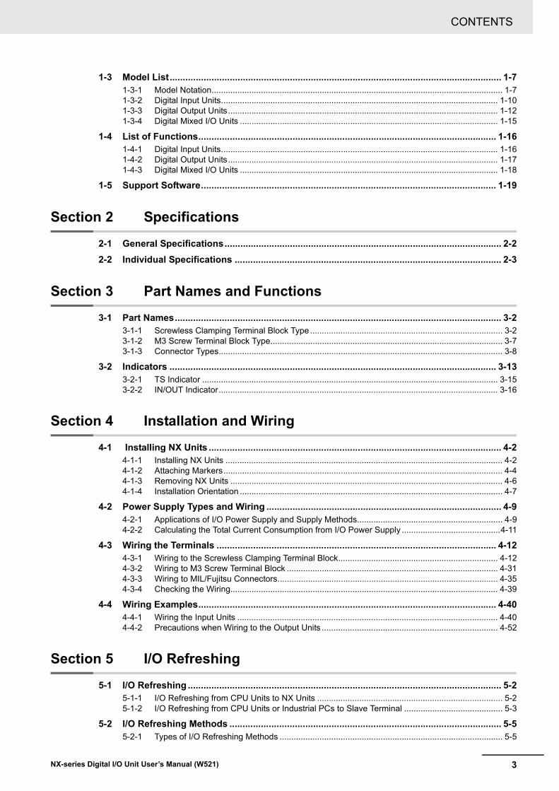
The table below provides the relevant manuals for the NX-series Digital I/O Units.
Read all of the manuals that are relevant to your system configuration and application to make the most of the NX-series Digital I/O Units.
Other manuals, such as related product manuals, are necessary for specific system configurations and applications. Refer to Related Manuals on page 27 for the related manuals.
Manual name ApplicationNX-series Digital I/O Units User's Manual
Learning how to use NX-series Digital I/O Units
NX-series Data Reference Man-ual
Referencing lists of the data that is required to configure systems with NX-series Units

Manual Structure
8 NX-series Digital I/O Unit User’s Manual (W521)
Manual Structure
The following page structure and icons are used in this manual.
Note This illustration is provided only as a sample. It may not literally appear in this manual.
Page Structure and Icons
4-9
4 Installation and Wiring
NJ-series CPU Unit Hardware User’s Manual (W500)
stin
U gn
itnu
oM
3-4
4
stne
nop
moC r
ellort
noC
gnit
cenn
oC
1-3-
4
4-3 Mounting Units
The Units that make up an NJ-series Controller can be connected simply by pressing the Units togetherand locking the sliders by moving them toward the back of the Units. The End Cover is connected in thesame way to the Unit on the far right side of the Controller.
1 Join the Units so that the connectors fit exactly.
2 The yellow sliders at the top and bottom of each Unit lock the Units together. Move the sliderstoward the back of the Units as shown below until they click into place.
Precautions for Correct UsePrecautions for Correct Use
4-3-1 Connecting Controller Components
ConnectorHook Hook holes
Slider
Lock
Release
Move the sliders toward the back until they lock into place.
Level 1 headingLevel 2 headingLevel 3 headingLevel 2 heading
A step in a procedure
Manual name
Special information
Level 3 heading
Page tab
Gives the current headings.
Indicates a procedure.
Icons indicate precautions, additional information, or reference information.
Gives the number of the main section.
The sliders on the tops and bottoms of the Power Supply Unit, CPU Unit, I/O Units, Special I/O Units, and CPU Bus Units must be completely locked (until they click into place) after connecting the adjacent Unit connectors.

9
Manual Structure
NX-series Digital I/O Unit User’s Manual (W521)
Special information in this manual is classified as follows:
Precautions for Safe Use
Precautions on what to do and what not to do to ensure safe usage of the product.
Precautions for Correct Use
Precautions on what to do and what not to do to ensure proper operation and performance.
Additional Information
Additional information to read as required.
This information is provided to increase understanding or make operation easier.
Version Information
Information on differences in specifications and functionality for CPU Units, Industrial PCs, and Communications Coupler Units with different unit versions and for different versions of the Sup-port Software is given.
Note References are provided to more detailed or related information.
Special Information

Manual Structure
10 NX-series Digital I/O Unit User’s Manual (W521)
• In this manual, “download” refers to transferring data from the Support Software to a physical device and “upload” refers to transferring data from a physical device to the Support Software.
• In this manual, the directions in relation to the Units are given in the following figure, which shows upright installation.
• This user's manual refers to the NY-series IPC Machine Controller Industrial Panel PCs and Indus-trial Box PCs as simply Industrial PCs or as NY-series Industrial PCs.
• This user's manual refers to the built-in EtherCAT port on an NJ/NX-series Controller or NY-series Industrial PC as simple a built-in EtherCAT port.
• This user's manual may omit manual names and manual numbers in places that refer to the user's manuals for CPU Units and Industrial PCs. The following table gives some examples. When neces-sary, refer to Related Manuals on page 27 to determine the appropriate manual based on the com-mon text for the omitted contents.
Examples:
• This user’s manual may omit manual names and manual numbers in places that refer to the user's manuals for Communications Coupler Units. If you will use a Communications Coupler Unit, refer to Related Manuals on page 27 to identify the manual for your Unit.
Precaution on Terminology
Manual name Omitted contents Common textNJ/NX-series CPU Unit Software User's Manual
Software user's manual for the con-nected CPU Unit or Industrial PC
Software User's Manual
NY-seriesIPC Machine Controller Industrial Panel PC / Industrial Box PCSoftware User’s ManualNJ/NX-series CPU Unit Built-in EtherCAT® Port User's Manual
User's manual for built-in EtherCAT port on the connected CPU Unit or Industrial PC
Built-in EtherCAT port
NY-seriesIPC Machine Controller Industrial Panel PC / Industrial Box PCBuilt-in EtherCAT® PortUser’s Manual
RightLeft
Up
Down

11
Terms and Conditions Agreement
NX-series Digital I/O Unit User’s Manual (W521)
Terms and Conditions Agreement
Exclusive WarrantyOmron’s exclusive warranty is that the Products will be free from defects in materials and workman-ship for a period of twelve months from the date of sale by Omron (or such other period expressed in writing by Omron). Omron disclaims all other warranties, express or implied.
LimitationsOMRON MAKES NO WARRANTY OR REPRESENTATION, EXPRESS OR IMPLIED, ABOUT NON-INFRINGEMENT, MERCHANTABILITY OR FITNESS FOR A PARTICULAR PURPOSE OF THE PRODUCTS. BUYER ACKNOWLEDGES THAT IT ALONE HAS DETERMINED THAT THE PRODUCTS WILL SUITABLY MEET THE REQUIREMENTS OF THEIR INTENDED USE.
Omron further disclaims all warranties and responsibility of any type for claims or expenses based on infringement by the Products or otherwise of any intellectual property right.
Buyer RemedyOmron’s sole obligation hereunder shall be, at Omron’s election, to (i) replace (in the form originally shipped with Buyer responsible for labor charges for removal or replacement thereof) the non-com-plying Product, (ii) repair the non-complying Product, or (iii) repay or credit Buyer an amount equal to the purchase price of the non-complying Product; provided that in no event shall Omron be responsible for warranty, repair, indemnity or any other claims or expenses regarding the Products unless Omron’s analysis confirms that the Products were properly handled, stored, installed and maintained and not subject to contamination, abuse, misuse or inappropriate modification. Return of any Products by Buyer must be approved in writing by Omron before shipment. Omron Companies shall not be liable for the suitability or unsuitability or the results from the use of Products in combi-nation with any electrical or electronic components, circuits, system assemblies or any other materi-als or substances or environments. Any advice, recommendations or information given orally or in writing, are not to be construed as an amendment or addition to the above warranty.
See http://www.omron.com/global/ or contact your Omron representative for published information.
OMRON COMPANIES SHALL NOT BE LIABLE FOR SPECIAL, INDIRECT, INCIDENTAL, OR CON-SEQUENTIAL DAMAGES, LOSS OF PROFITS OR PRODUCTION OR COMMERCIAL LOSS IN ANY WAY CONNECTED WITH THE PRODUCTS, WHETHER SUCH CLAIM IS BASED IN CONTRACT, WARRANTY, NEGLIGENCE OR STRICT LIABILITY.
Further, in no event shall liability of Omron Companies exceed the individual price of the Product on which liability is asserted.
Warranty, Limitations of Liability
Warranties
Limitation on Liability; Etc
Terms and Conditions Agreement
12 NX-series Digital I/O Unit User’s Manual (W521)
Omron Companies shall not be responsible for conformity with any standards, codes or regulations which apply to the combination of the Product in the Buyer’s application or use of the Product. At Buyer’s request, Omron will provide applicable third party certification documents identifying ratings and limitations of use which apply to the Product. This information by itself is not sufficient for a com-plete determination of the suitability of the Product in combination with the end product, machine, sys-tem, or other application or use. Buyer shall be solely responsible for determining appropriateness of the particular Product with respect to Buyer’s application, product or system. Buyer shall take applica-tion responsibility in all cases.
NEVER USE THE PRODUCT FOR AN APPLICATION INVOLVING SERIOUS RISK TO LIFE OR PROPERTY WITHOUT ENSURING THAT THE SYSTEM AS A WHOLE HAS BEEN DESIGNED TO ADDRESS THE RISKS, AND THAT THE OMRON PRODUCT(S) IS PROPERLY RATED AND INSTALLED FOR THE INTENDED USE WITHIN THE OVERALL EQUIPMENT OR SYSTEM.
Omron Companies shall not be responsible for the user’s programming of a programmable Product, or any consequence thereof.
Data presented in Omron Company websites, catalogs and other materials is provided as a guide for the user in determining suitability and does not constitute a warranty. It may represent the result of Omron’s test conditions, and the user must correlate it to actual application requirements. Actual perfor-mance is subject to the Omron’s Warranty and Limitations of Liability.
Product specifications and accessories may be changed at any time based on improvements and other reasons. It is our practice to change part numbers when published ratings or features are changed, or when significant construction changes are made. However, some specifications of the Product may be changed without any notice. When in doubt, special part numbers may be assigned to fix or establish key specifications for your application. Please consult with your Omron’s representative at any time to confirm actual specifications of purchased Product.
Information presented by Omron Companies has been checked and is believed to be accurate; how-ever, no responsibility is assumed for clerical, typographical or proofreading errors or omissions.
Application Considerations
Suitability of Use
Programmable Products
Disclaimers
Performance Data
Change in Specifications
Errors and Omissions

13
Safety Precautions
NX-series Digital I/O Unit User’s Manual (W521)
Safety Precautions
The following notation is used in this manual to provide precautions required to ensure safe usage of an NX-series Digital I/O Unit.
The safety precautions that are provided are extremely important to safety. Always read and heed the information provided in all safety precautions.
The following notation is used.
Definition of Precautionary Information
Symbols
The circle and slash symbol indicates operations that you must not do.
The specific operation is shown in the circle and explained in text.
This example indicates prohibiting disassembly.
The triangle symbol indicates precautions (including warnings).
The specific operation is shown in the triangle and explained in text.
This example indicates a precaution for electric shock.
The triangle symbol indicates precautions (including warnings).
The specific operation is shown in the triangle and explained in text.
This example indicates a general precaution.
The filled circle symbol indicates operations that you must do.
The specific operation is shown in the circle and explained in text.
This example shows a general precaution for something that you must do.
WARNING
Caution
Indicates a potentially hazardous situation which, if not avoided, could result in death or serious injury. Additionally, there may be severe property damage.
Indicates a potentially hazardous situation which, if not avoided, may result in minor or moderate injury, or property damage.
Safety Precautions
14 NX-series Digital I/O Unit User’s Manual (W521)
Warnings
During Power Supply
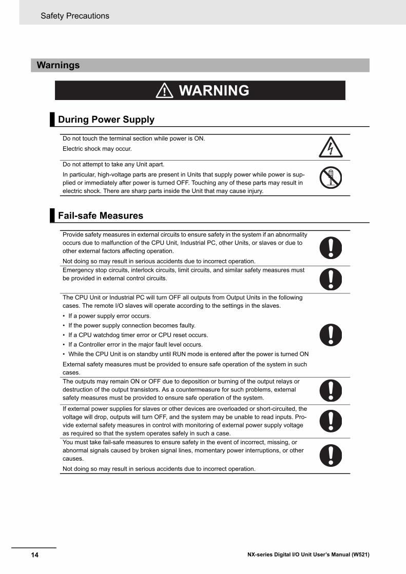
Do not touch the terminal section while power is ON.
Electric shock may occur.
Do not attempt to take any Unit apart.
In particular, high-voltage parts are present in Units that supply power while power is sup-plied or immediately after power is turned OFF. Touching any of these parts may result in electric shock. There are sharp parts inside the Unit that may cause injury.
Fail-safe Measures
Provide safety measures in external circuits to ensure safety in the system if an abnormality occurs due to malfunction of the CPU Unit, Industrial PC, other Units, or slaves or due to other external factors affecting operation.
Not doing so may result in serious accidents due to incorrect operation.Emergency stop circuits, interlock circuits, limit circuits, and similar safety measures must be provided in external control circuits.
The CPU Unit or Industrial PC will turn OFF all outputs from Output Units in the following cases. The remote I/O slaves will operate according to the settings in the slaves.
• If a power supply error occurs.• If the power supply connection becomes faulty.• If a CPU watchdog timer error or CPU reset occurs.• If a Controller error in the major fault level occurs.• While the CPU Unit is on standby until RUN mode is entered after the power is turned ON
External safety measures must be provided to ensure safe operation of the system in such cases.The outputs may remain ON or OFF due to deposition or burning of the output relays or destruction of the output transistors. As a countermeasure for such problems, external safety measures must be provided to ensure safe operation of the system.
If external power supplies for slaves or other devices are overloaded or short-circuited, the voltage will drop, outputs will turn OFF, and the system may be unable to read inputs. Pro-vide external safety measures in control with monitoring of external power supply voltage as required so that the system operates safely in such a case.You must take fail-safe measures to ensure safety in the event of incorrect, missing, or abnormal signals caused by broken signal lines, momentary power interruptions, or other causes.
Not doing so may result in serious accidents due to incorrect operation.
WARNING

15
Safety Precautions
NX-series Digital I/O Unit User’s Manual (W521)
Voltage and Current Inputs
Make sure that the voltages and currents that are input to the Units and slaves are within the specified ranges.
Inputting voltages or currents that are outside of the specified ranges may cause accidents or fire.
Transferring
Always confirm safety at the destination node before you transfer Unit configuration infor-mation, parameters, settings, or other data from tools such as the Sysmac Studio.
The devices or machines may operate unexpectedly, regardless of the operating mode of the Controller.
Cautions
Wiring
When you connect a computer or other peripheral device to a Communications Coupler Unit that has a non-isolated DC power supply, either ground the 0-V side of the external power supply (i.e. Unit power supply) or do not ground it at all.
If the peripheral devices are grounded incorrectly, the external power supply (i.e. Unit power supply) may be short-circuited.
Never ground the 24-V side of the power supply, as shown in the following figure.
Be sure that all terminal screws and cable connector screws are tightened to the torque specified in the relevant manuals. The loose screws may result in fire or malfunction.
Caution
Peripheral device (e.g., computer)
Non-isolated DC power supply (internal power
supply circuit)
24 V 0 V
Peripheral device cable
Ground terminal
Communications Coupler UnitNX Unit power supply
Unit power supply

Safety Precautions
16 NX-series Digital I/O Unit User’s Manual (W521)
Online Editing
Execute online editing only after confirming that no adverse effects will be caused by devia-tions in the timing of I/O. If you perform online editing, the task execution time may exceed the task period, I/O may not be refreshed with external devices, input signals may not be read, and output timing may change.

17
Precautions for Safe Use
NX-series Digital I/O Unit User’s Manual (W521)
Precautions for Safe Use
• When transporting any Unit, use the special packing box for it.Also, do not subject the Unit to excessive vibration or shock during transportation.
• Do not drop any Unit or subject it to abnormal vibration or shock.Doing so may result in Unit malfunction or burning.
• Mount terminal blocks and connectors only after checking the mounting location carefully.• Be sure that the terminal blocks, expansion cables, and other items with locking devices are properly
locked into place.
• Do not apply labels or tape to the Unit. When the Unit is installed or removed, adhesive or scraps may adhere to the pins in the NX bus connector, which may result in malfunctions.
• Do not touch the pins in the NX bus connector on the Unit. Dirt may adhere to the pins in the NX bus connector, which may result in malfunctions.
Transporting
Mounting
Installation
Example: NX Unit (12 mm width)
NG NG

Precautions for Safe Use
18 NX-series Digital I/O Unit User’s Manual (W521)
• Do not write on an NX Unit with ink within the restricted region that is shown in the following figure. Also do not get this area dirty. When the Unit is installed or removed, ink or dirt may adhere to the pins in the NX bus connector, which may result in malfunctions in the CPU Rack or the Slave Termi-nal. Refer to the user’s manual for the connected CPU Unit or Communications Coupler Unit for the restricted region of CPU Unit and Communications Coupler Unit.
• For the installation orientations in the following figure, support the cables, e.g., with a duct, so that the End Plate on the bottom is not subjected to the weight of the cables. The weight of the cables may cause the bottom End Plate to slide downward so that the Slave Terminal is no longer secured to the DIN Track, which may result in malfunctions.
Restricted region (shaded
portion)
Up
Down

19
Precautions for Safe Use
NX-series Digital I/O Unit User’s Manual (W521)
• Double-check all switches and other settings and double-check all wiring to make sure that they are correct before turning ON the power supply.
• Use the correct wiring parts and tools when you wire the system.• Do not pull on the cables or bend the cables beyond their natural limit. Also, do not place heavy
objects on top of the cables or other wiring lines. Doing so may break the cable.• When wiring or installing the Units, do not allow metal fragments to enter the Units.• Do not press the flat-blade screwdriver straight into the release holes on a screwless clamping termi-
nal block. Doing so may damage the terminal block.
• When you insert a flat-blade screwdriver into a release hole on a screwless clamping terminal block, press it down with a force of 30N or less. Applying excessive force may damage the terminal block.
• Do not incline or twist the flat-blade screwdriver while it is in a release hole on a screwless clamping terminal block. Doing so may damage the terminal block.
• If you use reed switches for the input contacts for AC Input Units, use switches with an allowable cur-rent of 1 A or greater. If the capacity of the reed switches is too low, inrush current may fuse the con-tacts.
• Use crimp terminals for wiring the M3 screw terminal blocks. Do not connect bare stranded wires directly to the M3 screw terminal blocks.
• Use all Units within the I/O power supply ranges that are given in the specifications.• Use the I/O power supply current for the CPU Rack of the NX-series NX1P2 CPU Unit at 4 A or less.
Using the currents that are outside of the specifications may cause failure or damage.• Supply sufficient power according to the contents of this manual.• Use the power supply voltage that is specified in this manual.• Do not apply voltages that exceed the rated value to any Input Unit.• Do not apply voltages or connect loads to the Output Units or slaves in excess of the maximum rat-
ings.• Inrush current occurs when the power supply is turned ON. When selecting fuses or breakers for
external circuits, consider their fusing and detection characteristics as well as the above precautions and allow sufficient margin in shut-off performance.
• Install external breakers and take other safety measures against short-circuiting and overcurrents in external wiring.
Wiring
Power Supply Design
NG OK
NG NG

Precautions for Safe Use
20 NX-series Digital I/O Unit User’s Manual (W521)
• When you set the Operating Mode at Startup, confirm that no adverse effect will occur in the system.
• Before you start operation, always register the NX Units that are connected to the Communications Coupler Unit in the host communications master as the Unit Configuration Information.
• Check the user program, data, and parameter settings for proper execution before you use them for actual operation.
• If you change the fail-soft operation setting, the output status when the error occurs may also change. Confirm safety before you change the fail-soft operation setting.
• If you use fail-soft operation, write programming to determine whether Unit I/O data is valid. Without such programming, the user program cannot distinguish between Units for which I/O refreshing is continued and Units for which I/O refreshing is stopped.
• Do not disconnect the cable or turn OFF the power supply to the Controller or a Slave Terminal when downloading data or the user program from the Support Software.
• Always turn OFF the external power supply to the Units before attempting any of the following.
Mounting or removing an NX Unit, Communications Coupler Unit, CPU Unit, or Industrial PCAssembling UnitsSetting DIP switches or rotary switchesConnecting or wiring cablesAttaching or removing terminal blocks or connectors
Units that supply power continue to supply power to the Units for up to several seconds after the power supply is turned OFF. The PWR indicator remains lit as long as power is supplied. Confirm that the PWR indicator is not lit before you perform any of the above.
• Confirm that the controlled system will not be adversely affected before you perform any of the fol-lowing operations.
Changing the operating mode of the CPU Unit or the Industrial PC (including changing the setting of the Operating Mode at Startup)Changing the user program or settingsChanging set values or present valuesForced refreshing
• Always sufficiently check the safety at the connected devices before you change the settings of a slave or Unit.
• Do not exceed the ranges that are given in the specifications for the communications distance and number of connected Units.
• Refer to the user’s manual for the Communications Coupler Unit for precautions for the safe use of communications with the connected Communications Coupler Unit.
Turning ON the Power Supply
Actual Operation
Turning OFF the Power Supply
Operation
General Communications
21
Precautions for Safe Use
NX-series Digital I/O Unit User’s Manual (W521)
• When you replace a Unit, start operation only after you transfer the settings and variables that are required for operation to the new Unit.
• Dispose of the product according to local ordinances as they apply.
Unit Replacement
Disposal

Precautions for Correct Use
22 NX-series Digital I/O Unit User’s Manual (W521)
Precautions for Correct Use
• Follow the instructions in this manual to correctly perform installation and wiring.• Do not operate or store the Units in the following locations. Doing so may result in malfunction, in
operation stopping, or in burning.
Locations subject to direct sunlightLocations subject to temperatures or humidity outside the range specified in the specificationsLocations subject to condensation as the result of severe changes in temperatureLocations subject to corrosive or flammable gasesLocations subject to dust (especially iron dust) or saltsLocations subject to exposure to water, oil, or chemicalsLocations subject to shock or vibration
• Take appropriate and sufficient countermeasures during installation in the following locations.
Locations subject to strong, high-frequency noiseLocations subject to static electricity or other forms of noiseLocations subject to strong electromagnetic fieldsLocations subject to possible exposure to radioactivityLocations close to power lines
• Before touching a Unit, be sure to first touch a grounded metallic object in order to discharge any static build-up.
• Use the rated power supply voltage for the Units that supply power. Take appropriate measures to ensure that the specified power with the rated voltage and frequency is supplied in places where the power supply is unstable.
• Install the Units away from sources of heat and ensure proper ventilation. Not doing so may result in malfunction, in operation stopping, or in burning.
• Do not allow foreign matter to enter the openings in the Unit. Doing so may result in Unit burning, electric shock, or failure.
• If you change the event level of an error, the output status when the error occurs may also change. Confirm safety before you change an event level.
• Do not turn OFF the power supply while data is being transferred.• Do not turn OFF the power supply while parameters are being written to the CPU Unit, the Communi-
cations Coupler Unit or NX Units.
• Refer to the user’s manual for the Communications Coupler Unit for precautions for the correct use of communications with the connected Communications Coupler Unit.
Storage, Mounting, and Wiring
Actual Operation
Turning OFF the Power Supply
General Communications

23
Regulations and Standards
NX-series Digital I/O Unit User’s Manual (W521)
Regulations and Standards
• EMC Directives• Low Voltage Directive
EMC DirectivesOMRON devices that comply with EU Directives also conform to the related EMC standards so that they can be more easily built into other devices or the overall machine. The actual products have been checked for conformity to EMC standards.*1
Whether the products conform to the standards in the system used by the customer, however, must be checked by the customer. EMC-related performance of the OMRON devices that comply with EU Directives will vary depending on the configuration, wiring, and other conditions of the equipment or control panel on which the OMRON devices are installed. The customer must, therefore, perform the final check to confirm that devices and the overall machine conform to EMC standards.
*1. Applicable EMC (Electromagnetic Compatibility) standards are as follows:EMS (Electromagnetic Susceptibility): EN 61131-2EMI (Electromagnetic Interference): EN 61131-2 (Radiated emission: 10-m regulations).
Low Voltage DirectiveAlways ensure that devices operating at voltages of 50 to 1,000 VAC and 75 to 1,500 VDC meet the required safety standards. The applicable directive is EN 61010-2-201.
Conformance to EU DirectivesThe NX-series Units comply with EU Directives. To ensure that the machine or device in which the NX-series Units are used complies with EU Directives, the following precautions must be observed.• The NX-series Units must be installed within a control panel.• You must use SELV power supply for the DC power supplies that are connected as the Unit power
supplies and I/O power supplies for the NX-series Units.We recommend that you use the OMRON S8VK-S series Power Supplies for the CPU Racks with NX-series NX1P2 CPU Units. We recommend that you use the OMRON S8JX-series Power Sup-plies for Slave Terminals. EMC standard compliance was confirmed for these recommended Power Supplies.
• NX-series Units that comply with EU Directives also conform to the Common Emission Standard (EN 61131-2). Radiated emission characteristics (10-m regulations) may vary depending on the configuration of the control panel used, other devices connected to the control panel, wiring, and other conditions.You must therefore confirm that the overall machine or equipment in which the NX-series Units are used complies with EU Directives.
• You must use power supplies with an output hold time of 10 ms or longer for the DC power sup-plies that are connected as the Unit power supplies and I/O power supplies for the NX-series Units.
Conformance to EU Directives
Applicable Directives
Concepts

Regulations and Standards
24 NX-series Digital I/O Unit User’s Manual (W521)
• This is a Class A product (for industrial environments). In a residential environment, it may cause radio interference. If radio interference occurs, the user may be required to take appropriate mea-sures.
Some NX-series products comply with UL and CSA standards. If you use an NX-series product that complies with UL or CSA standards and the machinery or system in which you use the NX-series prod-uct must also comply with the standards, refer to the Instruction Sheet that is provided with the product. The Instruction Sheet provides the application conditions for complying with the standards.
Some NX-series products comply with shipbuilding standards. If you use an NX-series product that complies with shipbuilding standards and the machinery or system in which you use the NX-series product must also comply with the standards, consult with your OMRON representative. Application conditions are defined according to the installation location. Application may not be possible for some installation locations.
For usage conditions for shipbuilding standards, refer to Conformance to Shipping Standards in the user's manual for the CPU Unit or Communications Coupler Unit that the NX Units are connected to.
Observe the following precaution if you use NX-series Units in Korea.
Class A Device (Broadcasting Communications Device for Office Use)
This device obtained EMC registration for office use (Class A), and it is intended to be used in places other than homes.
Sellers and/or users need to take note of this.
This product incorporates certain third party software. The license and copyright information associated with this software is available at http://www.fa.omron.co.jp/nj_info_e/.
Conformance to UL and CSA Standards
Conformance to Shipbuilding Standards
Conformance to KC Standards
Software Licenses and Copyrights

25
Unit Versions
NX-series Digital I/O Unit User’s Manual (W521)
Unit Versions
This section describes the notation that is used for unit versions, the confirmation method for unit ver-sions, and the relationship between unit versions and Support Software versions.
A “unit version” has been introduced to manage the Units in the NX Series according to differences in functionality accompanying Unit upgrades.
An example is provided below for Communications Coupler Units and NX Units. For the notation that is used for the unit versions of CPU Units or Industrial PCs and the confirmation method for unit versions, refer to the user’s manual for each Unit.
The unit version is given with the Unit specifications on the side of the Unit or in the notched area.
Unit Versions
Notation of Unit Versions on Products
Notched area
Unit specifications
LOT No.
Unit versionLot number
Unit model numberLot number and unit version
Unit Versions
26 NX-series Digital I/O Unit User’s Manual (W521)
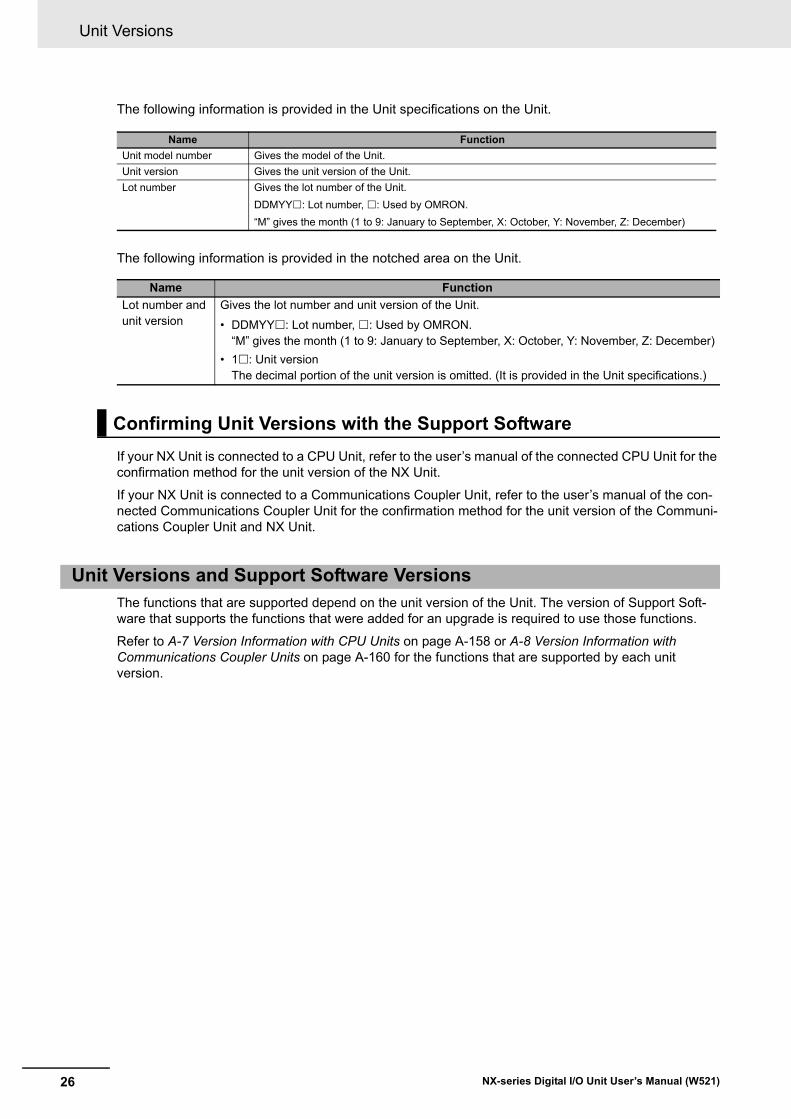
The following information is provided in the Unit specifications on the Unit.
The following information is provided in the notched area on the Unit.
If your NX Unit is connected to a CPU Unit, refer to the user’s manual of the connected CPU Unit for the confirmation method for the unit version of the NX Unit.
If your NX Unit is connected to a Communications Coupler Unit, refer to the user’s manual of the con-nected Communications Coupler Unit for the confirmation method for the unit version of the Communi-cations Coupler Unit and NX Unit.
The functions that are supported depend on the unit version of the Unit. The version of Support Soft-ware that supports the functions that were added for an upgrade is required to use those functions.
Refer to A-7 Version Information with CPU Units on page A-158 or A-8 Version Information with Communications Coupler Units on page A-160 for the functions that are supported by each unit version.
Name FunctionUnit model number Gives the model of the Unit.Unit version Gives the unit version of the Unit.Lot number Gives the lot number of the Unit.
DDMYY: Lot number, : Used by OMRON.“M” gives the month (1 to 9: January to September, X: October, Y: November, Z: December)
Name FunctionLot number and unit version
Gives the lot number and unit version of the Unit.
• DDMYY: Lot number, : Used by OMRON.“M” gives the month (1 to 9: January to September, X: October, Y: November, Z: December)
• 1: Unit versionThe decimal portion of the unit version is omitted. (It is provided in the Unit specifications.)
Confirming Unit Versions with the Support Software
Unit Versions and Support Software Versions

27
Related Manuals
NX-series Digital I/O Unit User’s Manual (W521)
Related Manuals
The following table shows related manuals. Use these manuals for reference.
Manual name Cat. No. Model numbers Application DescriptionNX-series Digital I/O Units User’s Manual
W521 NX-ID
NX-IA
NX-OC
NX-OD
NX-MD
Learning how to use NX-series Dig-ital I/O Units
The hardware, setup methods, and functions of the NX-series Digital I/O Units are described.
NX-series Data Refer-ence Manual
W525 NX- Referencing lists of the data that is required to config-ure systems with NX-series Units
Lists of the power consumptions, weights, and other NX Unit data that is required to configure systems with NX-series Units are provided.
NX-series System Units User’s Manual
W523 NX-PD1
NX-PF0
NX-PC0
NX-TBX01
Learning how to use NX-series System Units
The hardware and functions of the NX-series System Units are described.
Sysmac Studio Version 1 Operation Manual
W504 SYSMAC-SE2
Learning about the operating proce-dures and func-tions of the Sysmac Studio
Describes the operating procedures of the Sysmac Studio.
NX-IO Configurator Operation Manual
W585 CXONE-ALD-V4
Learning about the operating proce-dures and func-tions of the NX-IO Configurator.
Describes the operating procedures of the NX-IO Configurator.
NJ/NX-series Trouble-shooting Manual
W503 NX701-
NJ501-
NJ301-
NJ101-
NX1P2-
Learning about the errors that may be detected in an NJ/NX-series Con-troller
Concepts on managing errors that may be detected in an NJ/NX-series Con-troller and information on individual errors are described.
NY-seriesTroubleshooting Manual
W564 NY532-
NY512-
Learning about the errors that may be detected in an NY-series Indus-trial PC
Concepts on managing errors that may be detected in an NY-series Controller and information on individual errors are described.
NX-series EtherCAT® Coupler Unit User’s Manual
W519 NX-ECC20 Learning how to use an NX-series EtherCAT Coupler Unit and Ether-CAT Slave Termi-nals
The following items are described: the overall system and configuration meth-ods of an EtherCAT Slave Terminal (which consists of an NX-series Ether-CAT Coupler Unit and NX Units), and information on hardware, setup, and functions to set up, control, and monitor NX Units through EtherCAT.

Related Manuals
28 NX-series Digital I/O Unit User’s Manual (W521)
NX-series Ether-Net/IPTM Coupler Unit User’s Manual
W536 NX-EIC202 Learning how to use an NX-series EtherNet/IP Cou-pler Unit and Eth-erNet/IP Slave Terminals
The following items are described: the overall system and configuration meth-ods of an EtherNet/IP Slave Terminal (which consists of an NX-series Ether-Net/IP Coupler Unit and NX Units), and information on hardware, setup, and functions to set up, control, and monitor NX Units.
NX-series CPU Unit Hardware User’s Man-ual
W535 NX701- Learning the basic specifications of the NX-series NX701 CPU Units, including introduc-tory information, designing, installa-tion, and mainte-nance.
Mainly hardware information is pro-vided.
An introduction to the entire NX701 CPU Unit system is provided along with the following information on the CPU Unit.
• Features and system configuration
• Overview
• Part names and functions
• General specifications
• Installation and wiring
• Maintenance and Inspection
NX-series NX1P2 CPU Unit Hardware User’s Manual
W578 NX1P2- Learning the basic specifications of the NX-series NX1P2 CPU Units, including introduc-tory information, designing, installa-tion, and mainte-nance. Mainly hardware informa-tion is provided.
An introduction to the entire NX1P2 CPU Unit system is provided along with the following information on the CPU Unit.
• Features and system configuration
• Overview
• Part names and functions
• General specifications
• Installation and wiring
• Maintenance and InspectionNJ-series CPU Unit Hardware User’s Man-ual
W500 NJ501-
NJ301-
NJ101-
Learning the basic specifications of the NJ-series CPU Units, including introductory infor-mation, designing, installation, and maintenance.
Mainly hardware information is pro-vided.
An introduction to the entire NJ-series system is provided along with the fol-lowing information on the CPU Unit.
• Features and system configuration
• Overview
• Part names and functions
• General specifications
• Installation and wiring
• Maintenance and Inspection
NY-series IPC Machine Controller Industrial Panel PC Hardware User’s Manual
W557 NY532- Learning the basic specifications of the NY-series Industrial Panel PCs, including introductory infor-mation, designing, installation, and maintenance. Mainly hardware information is pro-vided.
An introduction to the entire NY-series system is provided along with the fol-lowing information on the Industrial Panel PC.
• Features and system configuration
• Introduction
• Part names and functions
• General specifications
• Installation and wiring
• Maintenance and inspection
Manual name Cat. No. Model numbers Application Description

29
Related Manuals
NX-series Digital I/O Unit User’s Manual (W521)
NY-series IPC Machine Controller Industrial Box PC Hardware User's Manual
W556 NY512- Learning the basic specifications of the NY-series Industrial Box PCs, including introduc-tory information, designing, installa-tion, and mainte-nance. Mainly hardware informa-tion is provided.
An introduction to the entire NY-series system is provided along with the fol-lowing information on the Industrial Box PC.
• Features and system configuration
• Introduction
• Part names and functions
• General specifications
• Installation and wiring
• Maintenance and inspectionNJ/NX-series CPU Unit Software User's Manual
W501 NX701-
NJ501-
NJ301-
NJ101-
NX1P2-
Learning how to program and set up an NJ/NX-series CPU Unit.
Mainly software information is pro-vided.
The following information is provided on an NJ/NX-series CPU Unit.
• CPU Unit operation
• CPU Unit features
• Initial settings
• Programming based on IEC 61131-3 language specifications
NY-series IPC Machine Controller Industrial Panel PC / Industrial Box PC Software User’s Manual
W558 NY532-
NY512-
Learning how to program and set up the Controller functions of an NY-series Indus-trial PC
The following information is provided on NY-series Machine Automation Con-trol Software.
• Controller operation
• Controller features
• Controller settings
• Programming based on IEC 61131-3 language specifications
NJ/NX-series Instruc-tions Reference Manual
W502 NX701-
NJ501-
NJ301-
NJ101-
NX1P2-
Learning detailed specifications on the basic instruc-tions of an NJ/NX-series CPU Unit
The instructions in the instruction set (IEC 61131-3 specifications) are described.
NY-series Instructions Reference Manual
W560 NY532-
NY512-
Learning detailed specifications on the basic instruc-tions of an NY-series Indus-trial PC
The instructions in the instruction set (IEC 61131-3 specifications) are described.
Manual name Cat. No. Model numbers Application Description

Terminology
30 NX-series Digital I/O Unit User’s Manual (W521)
Terminology
Term Abbre-viation Description
application layer status, AL status --- Status for indicating information on errors that occur in an application on a slave.
CAN application protocol over Ether-CAT
CoE A CAN application protocol service implemented on EtherCAT.
CAN in Automation CiA CiA is the international users' and manufacturers' group that develops and supports higher-layer protocols.
Communications Coupler Units --- The generic name of an interface unit for remote I/O communications on a network between NX Units and a host network master.
CPU Rack --- A rack to which a CPU Unit is mounted. For an NX-series NX1P2 CPU Unit, a CPU Rack has a CPU Unit with NX Units and an End Cover mounted to it.
DC time --- Time indicated by the clock shared between the CPU Unit and the NX Units in a CPU Rack for an NX-series NX1P2 CPU Unit. EtherCAT slaves that support distributed clock synchronization have a clock that is shared by all slaves in the network. The time that is based on this distrib-uted clock is called the DC time. The same clock is shared by an NX-series NX1P2 CPU Unit, NX Units connected to the CPU Unit, and applicable EtherCAT slaves.
device profile --- A collection of device dependent information and functionality providing consistency between similar devices of the same device type.
device variable --- A variable that is used to access a specific device through an I/O port by an NJ/NX-series CPU Unit or NY-series Industrial PC. Process data on an EtherCAT slave is allocated to this variable. For an NX-series NX1P2 CPU Unit, I/O data for the NX Units on a CPU Unit is allocated. A user application on a CPU Unit or Industrial PC accesses a device that can be connected, by directly reading and writing this device variable.
distributed clock DC Clock distribution mechanism used to synchronize EtherCAT slaves and the EtherCAT master.
EtherCAT slave controller ESC A controller for EtherCAT slave communications.EtherCAT slave information ESI An XML file that contains setting information for an EtherCAT slave.EtherCAT state machine ESM An EtherCAT communications state machine.EtherCAT Technology Group ETG The ETG is a global organization in which OEM, end users, and technol-
ogy providers join forces to support and promote the further technology development.
I/O map settings --- Settings that assign variables to I/O ports. Assignment information between I/O ports and variables.
I/O port --- A logical interface that is used by the NJ/NX-series CPU Unit or NY-series Industrial PC to exchange data with an external device (slave or Unit).
I/O refreshing --- Cyclic data exchange with external devices that is performed with prede-termined memory addresses.
index --- Address of an object within an application process.network configuration information --- The EtherCAT network configuration information held by the EtherCAT
master.NX bus --- The NX-series internal bus.object --- An abstract representation of a particular component within a device,
which consists of data, parameters, and methods.object dictionary OD Data structure that contains description of data type objects, communi-
cation objects and application objects.

31
Terminology
NX-series Digital I/O Unit User’s Manual (W521)
Operational --- A state in EtherCAT communications where SDO communications and I/O are possible.
PDO communications --- An acronym for process data communications.Pre-Operational --- A state in EtherCAT communications where only SDO communications
are possible with the slaves, i.e., no I/O can be performed.primary periodic task --- The task with the highest priority.process data --- Collection of application objects designated to be downloaded cyclically
or acyclically for the purpose of measurement and control.process data communications --- One type of EtherCAT communications in which process data objects
(PDOs) are used to exchange information cyclically and in realtime. This is also called PDO communications.
process data object PDO A structure that describes the mappings of parameters that have one or more process data entities.
receive PDO RxPDO A process data object received by an EtherCAT slave.Safe-Operational --- A state in EtherCAT communications where only SDO communications
and reading input data from slaves are possible. Outputs from slaves are not performed.
SDO communications --- One type of EtherCAT communications in which service data objects (SDOs) are used to transmit information whenever required.
service data object SDO CoE asynchronous mailbox communications where all objects in the object dictionary can be read and written.
Slave Information Interface SII Slave information that is stored in non-volatile memory in the slave.Slave Terminal --- A building-block remote I/O terminal to which a Communications Cou-
pler Unit and NX Units are mountedsubindex --- Sub-address of an object within the object dictionary.Sync0 --- A signal that gives the interrupt timing based on the distributed clock
(DC) in EtherCAT communications. The slaves execute controls accord-ing to this interrupt timing.
Sync Manager SM Collection of control elements to coordinate access to concurrently used objects.
task period --- The interval at which the primary periodic task or a periodic task is exe-cuted.
transmit PDO TxPDO A process data object sent from an EtherCAT slave.
Term Abbre-viation Description

Revision History
32 NX-series Digital I/O Unit User’s Manual (W521)
Revision History
A manual revision code appears as a suffix to the catalog number on the front and back covers of the manual.
Revision code Date Revised content01 April 2013 Original production02 June 2013 Added time stamp refreshing, models on time stamp refreshing and cor-
rected mistakes.03 September 2013 Added information on the NX-IA3117/OC2733 and corrected mistakes.04 July 2014 Added information on the
NX-ID5142-5/ID6142-5/OD5121-5/OD5256-5/OD6121-5/OD6256-5/MD6121-5/MD6256-5 and corrected mistakes.
05 April 2015 • Added information on the NX-ID5142-1/ID6142-6/OD3268/OD5121-1/OD5256-1/OD6121-6/MD6121-6.
• Made changes accompanying the addition of the NX-series CPU Unit.• Corrected mistakes.
06 October 2016 • Made changes accompanying the addition of NX-OC4633.• Made changes to add NY-series IPC Machine Controller Industrial
Panel PCs and Industrial Box PCs.• Made changes accompanying the addition of the NX-series NX1P2
CPU Unit.• Corrected mistakes.
07 June 2017 • Made changes accompanying the upgrade of the NX-ECC203 unit ver-sion to version 1.5.
• Made changes accompanying the upgrade of the NX-EIC202 unit ver-sion to version 1.2.
• Corrected mistakes.
Cat. No. W521-E1-07Revision code

33
Sections in this Manual
NX-series Digital I/O Unit User’s Manual (W521)
1
2
3
4
5
6
7
8
9
1 10
2 A
3 I
4
5
6
7
8
9
Features and System Configuration
Specifications
Part Names andFunctions
Installation and Wiring
I Index
I/O Refreshing
10
A Appendices
Digital Output Units
Digital Input Units
Digital Mixed I/O Units
Troubleshooting
Inspection and Maintenance
Sections in this Manual

Sections in this Manual
34 NX-series Digital I/O Unit User’s Manual (W521)
1 - 1
1
NX-series Digital I/O Unit User’s Manual (W521)
This section describes NX system configuration and the types of Digital I/O Units.
1-1 Features and Types of Digital I/O Units . . . . . . . . . . . . . . . . . . . . . . . . . . . . 1-21-1-1 Digital I/O Unit Features . . . . . . . . . . . . . . . . . . . . . . . . . . . . . . . . . . . . . . . . . . 1-21-1-2 Digital I/O Unit Types . . . . . . . . . . . . . . . . . . . . . . . . . . . . . . . . . . . . . . . . . . . . 1-3
1-2 System Configuration . . . . . . . . . . . . . . . . . . . . . . . . . . . . . . . . . . . . . . . . . . 1-41-2-1 System Configuration in the Case of a CPU Unit . . . . . . . . . . . . . . . . . . . . . . . 1-41-2-2 System Configuration of Slave Terminals . . . . . . . . . . . . . . . . . . . . . . . . . . . . . 1-5
1-3 Model List . . . . . . . . . . . . . . . . . . . . . . . . . . . . . . . . . . . . . . . . . . . . . . . . . . . . 1-71-3-1 Model Notation . . . . . . . . . . . . . . . . . . . . . . . . . . . . . . . . . . . . . . . . . . . . . . . . . 1-71-3-2 Digital Input Units . . . . . . . . . . . . . . . . . . . . . . . . . . . . . . . . . . . . . . . . . . . . . . 1-101-3-3 Digital Output Units . . . . . . . . . . . . . . . . . . . . . . . . . . . . . . . . . . . . . . . . . . . . . 1-121-3-4 Digital Mixed I/O Units . . . . . . . . . . . . . . . . . . . . . . . . . . . . . . . . . . . . . . . . . . 1-15
1-4 List of Functions . . . . . . . . . . . . . . . . . . . . . . . . . . . . . . . . . . . . . . . . . . . . . 1-161-4-1 Digital Input Units . . . . . . . . . . . . . . . . . . . . . . . . . . . . . . . . . . . . . . . . . . . . . . 1-161-4-2 Digital Output Units . . . . . . . . . . . . . . . . . . . . . . . . . . . . . . . . . . . . . . . . . . . . . 1-171-4-3 Digital Mixed I/O Units . . . . . . . . . . . . . . . . . . . . . . . . . . . . . . . . . . . . . . . . . . 1-18
1-5 Support Software . . . . . . . . . . . . . . . . . . . . . . . . . . . . . . . . . . . . . . . . . . . . . 1-19
Features and System Configura-tion

1 Features and System Configuration
1 - 2 NX-series Digital I/O Unit User’s Manual (W521)
1-1 Features and Types of Digital I/O Units
This section describes features and types of Digital I/O Units.
The Digital I/O Units are NX Units to process inputs and outputs of digital signals (ON/OFF signals).
The NX-series Digital I/O Units have the following features.
NX Unit NX-series Digital I/O Units can be connected to the following Units.*1
• NX-series CPU Unit• NX-series Communications Coupler Unit
When a CPU Unit and a Communications Coupler Unit are used together, you can unify the methods for installing, wiring, and setting up NX Units, and eventually reduce design costs.
*1. For whether NX Units can be connected to the CPU Unit or Communications Coupler Unit to be used, refer to the user's manual for the CPU Unit or Communications Coupler Unit to be used.
When the NX-series CPU Units or EtherCAT Coupler Unit is used together with NX Units that support synchronous I/O refreshing, the I/O control of multiple NX Units can be synchronized at the time to syn-chronize with the refresh cycle of the NX bus.
This provides an accurate I/O control because it suppresses jitter in the I/O timing of multiple NX Units.
1-1-1 Digital I/O Unit Features
Can be Connected to a CPU Unit or Communications Coupler Unit
Synchronous I/O with Refresh Cycle of the NX Bus
NX Units: e.g., NX-series Degital I/O Units
NX-series EtherCAT Coupler Unit
NX-series NX1P2 CPU Unit
Example:

1 - 3
1 Features and System Configuration
NX-series Digital I/O Unit User’s Manual (W521)
1-1 Features and Types of Digi-
tal I/O U
nits
1
1-1-2 Digital I/O
Unit Types
You can use NX-series CPU Units or EtherCAT Coupler Units with NX Units that support input refresh-ing with input changed time and with other NX Units that support output refreshing with specified time stamp to control the outputs at fixed intervals after the sensor inputs change.
The terminal block is a screwless clamping terminal block.
You can connect the wires simply by pushing the ferrules into the terminals. The amount of wiring work is reduced without requiring the use of screws.
The types of Digital I/O Units are as follows.
Refer to 1-3 Model List on page 1-7 for details on Digital I/O Unit models and 1-4 List of Functions on page 1-16 for details on their functions.
Controlling Outputs at Fixed Intervals After Inputs Change
Simple I/O Wiring with a Screwless Clamping Terminal Block
1-1-2 Digital I/O Unit Types
Type PurposeDigital Input Units These are Units with functionality to process input of digital signals from sensors
and other connected external devices.Digital Output Units These are Units with functionality to process output of digital signals to relays and
other connected external devices.Digital Mixed I/O Units These are Units with functionality to process input of digital signals from connected
external devices as well as functionality to process output of digital signals to con-nected external devices.
External output device(Output)
Workpiece
Sensor(Input)
Fixed intervalWhen input changes When output is made

1 Features and System Configuration
1 - 4 NX-series Digital I/O Unit User’s Manual (W521)
1-2 System Configuration
NX Unit NX-series Digital I/O Units can be connected to the following Units.• NX-series CPU Unit• NX-series Communications Coupler Unit
The following explains the system configuration for each NX Unit connection destination.
The following figure shows a system configuration when a group of NX Units is connected to an NX-series CPU Unit.
You can connect the EtherCAT Slave Terminal to the built-in EtherCAT port on the CPU Unit. Refer to 1-2-2 System Configuration of Slave Terminals on page 1-5 for details on the system configuration of a Slave Terminal.
1-2-1 System Configuration in the Case of a CPU Unit
Sym-bol Item Description
(A) NX-series CPU Unit The Unit that serves as the center of control for a Machine Automation Con-troller. It executes tasks, refreshes I/O for other Units and slaves, etc. NX Units can be connected to an NX1P2 CPU Unit.
(B) NX Units The NX Units perform I/O processing with connected external devices. The NX Units exchange data with the CPU Unit through I/O refreshing. A maximum of eight NX Units can be connected to an NX1P2 CPU Unit.
(A) NX-series CPU Unit
EtherCAT Slave Terminal
(D) Support Software Sysmac Studio
Built-in EtherCAT port
Connect to built-in EtherNet/IP port
(B) NX Units
CPU Rack
NX1P2-
(C) End Cover
EtherCAT
NX Units
EtherCAT Coupler Unit

1 - 5
1 Features and System Configuration
NX-series Digital I/O Unit User’s Manual (W521)
1-2 System C
onfiguration
1
1-2-2 System C
onfiguration of Slave Term
inals
A building-block remote I/O slave provided with a group of NX Units connected to a Communications Coupler Unit is generically called a Slave Terminal.
The NX Units can be flexibly combined with a Communications Coupler Unit to achieve the optimum remote I/O slave for the application with less wiring, less work, and less space.
The following figure shows an example of the system configuration when an EtherCAT Coupler Unit is used as a Communications Coupler Unit.
Refer to the user's manual for the connected Communications Coupler Unit for details on how to config-ure the system when any other type of Communications Coupler Unit is used.
(C) End Cover The End Cover is attached to the end of a CPU Rack.(D) Support Software
(Sysmac Studio)
A computer software application for setting, programming, debugging, and troubleshooting NJ/NX/NY-series Controllers.
For an NX1P2 CPU Unit, this application performs setting operation by making a connection to a built-in EtherNet/IP port.
1-2-2 System Configuration of Slave Terminals
Sym-bol Item Description
(A) EtherCAT masterNJ/NX-series CPU Unit, NY-series Industrial PC,or master from another manufacturer
(G) Communications cableEthernet cables
(B) NX SeriesEtherCAT Coupler UnitNX-ECC20
• EtherCAT Slave Terminal
(E) Support Software*1
(E) Support Software
(F) ESI files
(D) End Cover
(C) NX Units
EtherCAT port
(F) ESI files
Peripheral USB port
.xml
.xml
Connection to peripheral USB port on EtherCAT Coupler Unit
*1. The connection method for the Support Software depends on the model of the CPU Unit or Industrial PC.

1 Features and System Configuration
1 - 6 NX-series Digital I/O Unit User’s Manual (W521)
Let-ter Item Description
(A) EtherCAT master *1
*1. An EtherCAT Slave Terminal cannot be connected to any of the OMRON CJ1W-NC81/82 Position Control Units even though they can operate as EtherCAT masters.
The EtherCAT master manages the network, monitors the status of slaves, and exchanges I/O data with slaves.
(B) EtherCAT Coupler Unit The EtherCAT Coupler Unit serves as an interface for process data communi-cations on the EtherCAT network between the NX Units and the EtherCAT master.
The I/O data for the NX Units is accumulated in the EtherCAT Coupler Unit and then all of the data is exchanged with the EtherCAT master at the same time.
The EtherCAT Coupler Unit can also perform message communications (SDO communications) with the EtherCAT master.
(C) NX Units The NX Units perform I/O processing with connected external devices.
The NX Units perform process data communications with the EtherCAT mas-ter through the EtherCAT Coupler Unit.
(D) End Cover The End Cover is attached to the end of the Slave Terminal.(E) Support Software*2 *3
*2. The term Support Software indicates software that is provided by OMRON. If you connect to a master from another company, use the software tool corresponding to that master.
*3. Refer to 1-5 Support Software on page 1-19 for information on Support Software.
The Support Software runs on a personal computer and it is used to configure the EtherCAT network and EtherCAT Slave Terminal, and to program, monitor, and troubleshoot the Controllers.
(F) ESI (EtherCAT Slave Information) file
The ESI files contain information that is unique to the EtherCAT Slave Termi-nals in XML format. You can load an ESI file into the Support Software to eas-ily allocate Slave Terminal process data and make other settings.
The ESI files for OMRON EtherCAT slaves are installed in the Support Soft-ware. You can obtain the ESI files for the latest models through the Support Software’s automatic update function.
(G) Communications cable Use a double-shielded cable with aluminum tape and braiding of Ethernet cat-egory 5 (100Base-TX) or higher, and use straight wiring.

1 - 7
1 Features and System Configuration
NX-series Digital I/O Unit User’s Manual (W521)
1-3 Model List
1
1-3-1 Model N
otation
1-3 Model List
The Digital I/O Unit models are assigned based on the following rules.
1-3-1 Model Notation
Number of points2 : 2 points3 : 4 points4 : 8 points5 : 16 points6 : 32 points, or 16 points each for inputs and outputs
I/O type
For both NPN/PNP−
NPNPNP−
−
For both NPN/PNP, NPNFor both NPN/PNP, PNP−
−
−
−
NPNPNP−
−
N.O.N.O. + N.C.
123467
Unit typeID : DC inputIA : AC inputOD : Transistor outputOC : Relay outputMD : DC input/Transistor output
NX - - - -
Number Inputs Outputs Mixed I/O (Input, Output)
Other specifications Refer to Other specifications on the next page.
External connection terminals
Screwless clamping terminal blockM3 screw terminal blockMIL connectorFujitsu connector
None-1-5-6
External connection terminalsNumber

1 Features and System Configuration
1 - 8 NX-series Digital I/O Unit User’s Manual (W521)
Digital Input Units
Digital Output Units
Other Specifications
Number Input voltage
ON/OFF response time I/O refreshing method
Exceeds 1 μs 1 μs max.
Free-Run refreshing *1 onlyor
Switching Synchronous I/O refreshing *2 and Free-Run
refreshing
*1. Free-Run refreshing*2. Synchronous I/O refreshing
Input refreshing with input changed time only
1712 to 24 VDC or 240 VAC
Yes --- Yes ---
4224 VDC
Yes --- Yes ---43 --- Yes Yes ---44 --- Yes --- Yes
Number
Rated volt-age
Load cur-rent
ON/OFF response time I/O refreshing method Other func-
tions
Exceeds 1 μs
1 μs max.
Free-Run refresh-ing *1 only
orSwitching Syn-chronous I/O
refreshing *2 and Free-Run refresh-
ing
*1. Free-Run refreshing*2. Synchronous I/O refreshing
Output refresh-ing with speci-fied time stamp
only
Load short-circuit protection
21 12 to 24 VDC or 240 VAC
0.5 A Yes --- Yes --- ---33 2 A Yes --- Yes --- ---53
24 VDC0.5 A
--- Yes Yes --- ---54 --- Yes --- Yes ---56 Yes --- Yes --- Yes57 --- Yes Yes --- Yes58 --- Yes --- Yes Yes68 2 A Yes --- Yes --- Yes
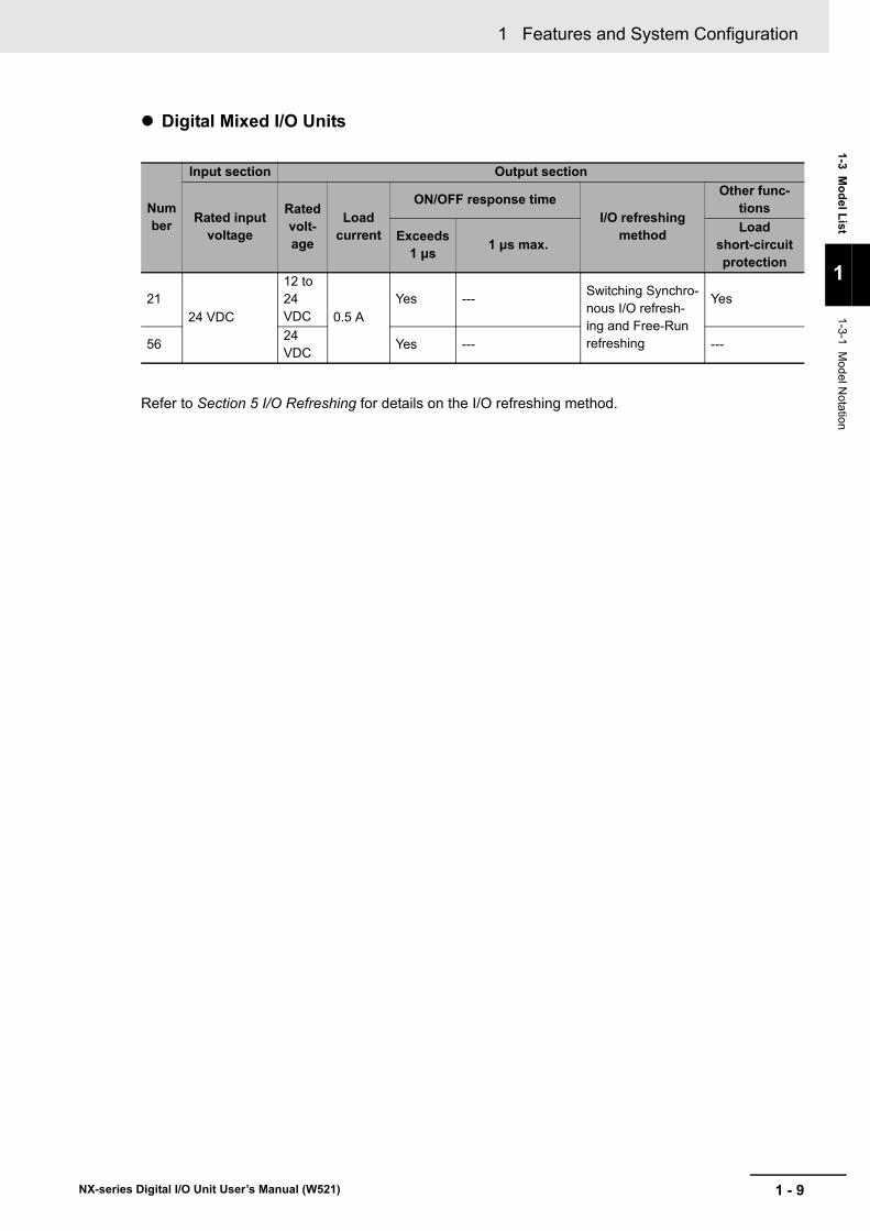
1 - 9
1 Features and System Configuration
NX-series Digital I/O Unit User’s Manual (W521)
1-3 Model List
1
1-3-1 Model N
otation
Digital Mixed I/O Units
Refer to Section 5 I/O Refreshing for details on the I/O refreshing method.
Number
Input section Output section
Rated input voltage
Rated volt-age
Load current
ON/OFF response timeI/O refreshing
method
Other func-tions
Exceeds 1 μs 1 μs max.
Load short-circuit protection
2124 VDC
12 to 24 VDC 0.5 A
Yes --- Switching Synchro-nous I/O refresh-ing and Free-Run refreshing
Yes
5624 VDC
Yes --- ---

1 Features and System Configuration
1 - 10 NX-series Digital I/O Unit User’s Manual (W521)
This section shows the specifications for Digital Input Units.
Refer to A-1-2 Digital Input Units on page A-7 for details on the specifications of individual Digital Input Units.
1-3-2 Digital Input Units
DC Input Units (Screwless Clamping Terminal Block, 12 mm Width)
Model
Number of
points
Internal I/O common
Rated input voltage
I/O refreshing method
ON/OFF response time Reference
NX-ID3317
4 points
NPN
12 to 24 VDC Switching Synchro-nous I/O refreshing and Free-Run refreshing
20 μs max./400 μs max. P. A-9
NX-ID3343
24 VDC 100 ns max./100 ns max.
P. A-11
NX-ID3344Input refreshing with input changed time only
P. A-13
NX-ID3417
PNP
12 to 24 VDC Switching Synchro-nous I/O refreshing and Free-Run refreshing
20 μs max./400 μs max. P. A-14
NX-ID3443
24 VDC
100 ns max./100 ns max.
P. A-16
NX-ID3444Input refreshing with input changed time only
P. A-17
NX-ID4342 8 points
NPNSwitching Synchro-nous I/O refreshing and Free-Run refreshing
20 μs max./400 μs max.
P. A-18
NX-ID4442 PNP P. A-20
NX-ID5342 16 points
NPN P. A-22
NX-ID5442 PNP P. A-24
DC Input Units (M3 Screw Terminal Block, 30 mm Width)
Model
Number of
points
Internal I/O common
Rated input voltage
I/O refreshing method
ON/OFF response time Reference
NX-ID5142-116 points
For both NPN/PNP 24 VDC
Switching Synchro-nous I/O refreshing and Free-Run refreshing
20 μs max./400 μs max. P. A-26

1 - 11
1 Features and System Configuration
NX-series Digital I/O Unit User’s Manual (W521)
1-3 Model List
1
1-3-2 Digital Input U
nits
DC Input Units (MIL Connector, 30 mm Width)
Model
Number of
points
Internal I/O common
Rated input voltage
I/O refreshing method
ON/OFF response time Reference
NX-ID5142-516 points
For both NPN/PNP 24 VDC Switching Synchro-
nous I/O refreshing and Free-Run refreshing
20 μs max./400 μs max.
P. A-28
NX-ID6142-532 points
For both NPN/PNP 24 VDC P. A-30
DC Input Units (Fujitsu Connector, 30 mm Width)
Model
Number of
points
Internal I/O common
Rated input voltage
I/O refreshing method
ON/OFF response time Reference
NX-ID6142-632 points
For both NPN/PNP 24 VDC
Switching Synchro-nous I/O refreshing and Free-Run refreshing
20 μs max./400 μs max. P. A-33
AC Input Units (Screwless Clamping Terminal Block, 12 mm Width)
Model
Number of
points
Rated input voltage I/O refreshing method
ON/OFF response time Reference
NX-IA31174 points
200 to 240 VAC, 50/60 Hz (170 to 264 VAC, ±3 Hz) Free-Run refreshing 10 ms max./40 ms
max. P. A-36

1 Features and System Configuration
1 - 12 NX-series Digital I/O Unit User’s Manual (W521)
This section shows the specifications for Digital Output Units.
Refer to A-1-3 Digital Output Units on page A-38 for details on the specifications of individual Digital Output Units.
1-3-3 Digital Output Units
Transistor Output Units (Screwless Clamping Terminal Block, 12 mm Width)
ModelNum-ber of points
Internal I/O common
Maximum value of load cur-
rent
Rated volt-age
I/O refresh-ing method
ON/OFF response
time
Refer-ence
NX-OD2154
2 points
NPN
0.5 A/point, 1 A/Unit 24 VDC
Output refreshing with speci-fied time stamp only
300 ns max./300 ns max.
P. A-40
NX-OD2258 PNP P. A-42
NX-OD3121
4 points
NPN
0.5 A/point, 2 A/Unit
12 to 24 VDC
Switching Synchro-nous I/O refreshing and Free-Run refreshing
0.1 ms max./0.8 ms max.
P. A-44
NX-OD3153
24 VDC
300 ns max./300 ns max.
P. A-46
NX-OD3256
PNP
0.5 ms max./1.0 ms max.
P. A-48
NX-OD3257300 ns max./300 ns max.
P. A-50
NX-OD3268 2 A/point, 8 A/Unit
0.5 ms max./1.0 ms max.
P. A-52
NX-OD4121
8 points
NPN
0.5 A/point, 4 A/Unit
12 to 24 VDC
0.1 ms max./0.8 ms max.
P. A-54
NX-OD4256 PNP 24 VDC0.5 ms max./1.0 ms max.
P. A-56
NX-OD512116 points
NPN 12 to 24 VDC
0.1 ms max./0.8 ms max.
P. A-58
NX-OD5256 PNP 24 VDC0.5 ms max./1.0 ms max.
P. A-60

1 - 13
1 Features and System Configuration
NX-series Digital I/O Unit User’s Manual (W521)
1-3 Model List
1
1-3-3 Digital O
utput Units
Transistor Output Units (M3 Screw Terminal Block, 30 mm Width)
ModelNum-ber of points
Internal I/O common
Maximum value of load cur-
rent
Rated volt-age
I/O refresh-ing method
ON/OFF response
time
Refer-ence
NX-OD5121-1
16 points
NPN
0.5 A/point, 5 A/Unit
12 to 24 VDC
Switching Synchro-nous I/O refreshing and Free-Run refreshing
0.1 ms max./0.8 ms max.
P. A-62
NX-OD5256-1 PNP 24 VDC0.5 ms max./1.0 ms max.
P. A-64
Transistor Output Units (MIL Connector, 30 mm Width)
ModelNum-ber of points
Internal I/O common
Maximum value of load cur-
rent
Rated volt-age
I/O refresh-ing method
ON/OFF response
time
Refer-ence
NX-OD5121-516 points
NPN0.5 A/point, 2 A/Unit
12 to 24 VDC
Switching Synchro-nous I/O refreshing and Free-Run refreshing
0.1 ms max./0.8 ms max.
P. A-66
NX-OD5256-5 PNP 24 VDC0.5 ms max./1.0 ms max.
P. A-68
NX-OD6121-532 points
NPN 0.5 A/point, 2 A/com-mon, 4 A/Unit
12 to 24 VDC
0.1 ms max./0.8 ms max.
P. A-70
NX-OD6256-5 PNP 24 VDC0.5 ms max./1.0 ms max.
P. A-72
Transistor Output Units (Fujitsu Connector, 30 mm Width)
ModelNum-ber of points
Internal I/O common
Maximum value of load cur-
rent
Rated volt-age
I/O refresh-ing method
ON/OFF response
time
Refer-ence
NX-OD6121-6 32 points NPN
0.5 A/point, 2 A/com-mon, 4 A/Unit
12 to 24 VDC
Switching Synchro-nous I/O refreshing and Free-Run refreshing
0.1 ms max./0.8 ms max.
P. A-74

1 Features and System Configuration
1 - 14 NX-series Digital I/O Unit User’s Manual (W521)
Relay Output Units (Screwless Clamping Terminal Block, 12 mm Width)
ModelNum-ber of points
Relay type Maximum switching capacity
I/O refresh-ing method
ON/OFF response
time
Refer-ence
NX-OC2633
2 points
N.O. 250 VAC/2 A (cosΦ = 1), 250 VAC/2 A (cosΦ = 0.4), 24 VDC/2 A,4 A/Unit
Free-Run refreshing
15 ms max./15 ms max.
P. A-76
NX-OC2733 N.O. + N.C. P. A-78
Relay Output Units (Screwless Clamping Terminal Block, 24 mm Width)
ModelNum-ber of points
Relay type Maximum switching capacity
I/O refresh-ing method
ON/OFF response
time
Refer-ence
NX-OC4633 8 points N.O.
250 VAC/2A (cosΦ = 1),250 VAC/2A (cosΦ = 0.4),24 VDC/2A,8 A/Unit
Free-Run refreshing
15 ms max./15 ms max.
P. A-80

1 - 15
1 Features and System Configuration
NX-series Digital I/O Unit User’s Manual (W521)
1-3 Model List
1
1-3-4 Digital M
ixed I/O U
nits
This section shows the specifications for Digital Mixed I/O Units.
Refer to A-1-4 Digital Mixed I/O Units on page A-82 for details on the specifications of individual Mixed I/O Units.
1-3-4 Digital Mixed I/O Units
DC Input/Transistor Output Units (MIL Connector, 30 mm Width)
ModelNum-ber of points
Internal I/O common
Maximum value of load cur-
rent
Rated volt-age
I/O refresh-ing method
ON/OFF response
time
Refer-ence
NX-MD6121-5Out-puts: 16 points
Inputs: 16 points
Outputs: NPN
Inputs: For both NPN/PNP
0.5 A/point, 2 A/Unit
Outputs: 12 to 24 VDC
Inputs: 24 VDC
Switching Synchro-nous I/O refreshing and Free-Run refreshing
Outputs: 0.1 ms max./0.8 ms max.
Inputs: 20 μs max./400 μs max.
P. A-84
NX-MD6256-5
Outputs: PNP
Inputs: For both NPN/PNP
Outputs: 24 VDC
Inputs: 24 VDC
Outputs: 0.5 ms max./1.0 ms max.
Inputs: 20 μs max./400 μs max.
P. A-88
DC Input/Transistor Output Units (Fujitsu Connector, 30 mm Width)
ModelNum-ber of points
Internal I/O common
Maximum value of load cur-
rent
Rated volt-age
I/O refresh-ing method
ON/OFF response
time
Refer-ence
NX-MD6121-6
Out-puts: 16 points
Inputs: 16 points
Outputs: NPN
Inputs: For both NPN/PNP
0.5 A/point, 2 A/Unit
Outputs: 12 to 24 VDC
Inputs: 24 VDC
Switching Synchro-nous I/O refreshing and Free-Run refreshing
Outputs: 0.1 ms max./0.8 ms max.
Inputs: 20 μs max./400 μs max.
P. A-92

1 Features and System Configuration
1 - 16 NX-series Digital I/O Unit User’s Manual (W521)
1-4 List of Functions
This section provides an overview of functions that the Digital I/O Units have.
Refer to the specifications of each model in A-1 Data Sheet on page A-2 for details on the functions.
1-4-1 Digital Input Units
Function name Description ReferenceFree-Run Refreshing With this I/O refreshing method, the refresh cycle of the NX
bus and the I/O refresh cycles of the NX Units are asynchro-nous.
5-2-4 Free-Run Refreshing on page 5-8
Synchronous I/O Refresh-ing
With this I/O refreshing method, the timing to read inputs or to refresh outputs is synchronized on a fixed interval between more than one NX Unit connected to a CPU Unit.
In addition, with this I/O refreshing method, the timing to read inputs or to refresh outputs is synchronized on a fixed interval between more than one NX Unit on more than one Slave Ter-minal.
5-2-5 Synchro-nous Input Refreshing on page 5-12
Time Stamp Refreshing With this I/O refreshing method, the NX Units record the DC times when inputs change or perform outputs at specified DC times. These times are not synchronized to the NX bus refresh cycles.
Data exchange between the NX Units and the CPU Unit and data exchange between the NX Units and the EtherCAT Cou-pler Unit are performed cyclically on the NX bus refresh cycles.
5-2-7 Time Stamp Refreshing on page 5-19
Input refreshing with input changed time
With this I/O refreshing method, the Input Units record the DC times when inputs changed.
5-2-8 Input Refreshing with Input Changed Time on page 5-20
Input Filter This function eliminates the chattering or the noises from input signals.
It is used to prevent the error reading due to the noises. You can set the filter time constant.
6-4-2 Input Filter on page 6-14

1 - 17
1 Features and System Configuration
NX-series Digital I/O Unit User’s Manual (W521)
1-4 List of Functions
1
1-4-2 Digital O
utput Units
1-4-2 Digital Output Units
Function name Description ReferenceFree-Run Refreshing With this I/O refreshing method, the refresh cycle of the NX
bus and the I/O refresh cycles of the NX Units are asynchro-nous.
5-2-4 Free-Run Refreshing on page 5-8
Synchronous I/O Refresh-ing
With this I/O refreshing method, the timing to read inputs or to refresh outputs is synchronized on a fixed interval between more than one NX Unit connected to a CPU Unit.
In addition, with this I/O refreshing method, the timing to read inputs or to refresh outputs is synchronized on a fixed interval between more than one NX Unit on more than one Slave Ter-minal.
5-2-6 Synchro-nous Output Refreshing on page 5-16
Time Stamp Refreshing With this I/O refreshing method, the NX Units record the DC times when inputs change or perform outputs at specified DC times. These times are not synchronized to the NX bus refresh cycles.
Data exchange between the NX Units and the CPU Unit and data exchange between the NX Units and the EtherCAT Cou-pler Unit are performed cyclically on the NX bus refresh cycles.
5-2-7 Time Stamp Refreshing on page 5-19
Output refreshing with specified time stamp
With this I/O refreshing method, the Output Units refresh out-puts at specified DC times.
5-2-9 Output Refreshing with Specified Time Stamp on page 5-27
Load Rejection Output Setting
A function that performs the preset output operation when the Digital Output Unit cannot receive output data due to an NX bus error or CPU Unit watchdog timer error, in the case of Units connected to a CPU Unit.
A function that performs the preset output operation when the Digital Output Unit cannot receive output data due to a host error on the Communications Coupler Unit or an error on the NX bus, in the case of Slave Terminals.
7-4-2 Load Rejec-tion Output Setting on page 7-13
Load Short-circuit Protec-tion
A function in which the output will turn OFF to protect the out-put circuit when an overload or load short-circuit occurs due to a failure of the connected external devices.
7-4-3 Load Short-circuit Pro-tection on page 7-17

1 Features and System Configuration
1 - 18 NX-series Digital I/O Unit User’s Manual (W521)
1-4-3 Digital Mixed I/O Units
Function name Description ReferenceFree-Run Refreshing With this I/O refreshing method, the refresh cycle of the NX
bus and the I/O refresh cycles of the NX Units are asynchro-nous.
5-2-4 Free-Run Refreshing on page 5-8
Synchronous I/O Refresh-ing
With this I/O refreshing method, the timing to read inputs or to refresh outputs is synchronized on a fixed interval between more than one NX Unit connected to a CPU Unit.
In addition, with this I/O refreshing method, the timing to read inputs or to refresh outputs is synchronized on a fixed interval between more than one NX Unit on more than one Slave Ter-minal.
5-2-5 Synchro-nous Input Refreshing on page 5-12
Input Filter This function eliminates the chattering or the noises from input signals.
It is used to prevent the error reading due to the noises. You can set the filter time constant.
6-4-2 Input Filter on page 6-14
Load Rejection Output Setting
A function that performs the preset output operation when the Digital Output Unit cannot receive output data due to an NX bus error or CPU Unit watchdog timer error, in the case of Units connected to a CPU Unit.
A function that performs the preset output operation when the Digital Output Unit cannot receive output data due to a host error on the Communications Coupler Unit or an error on the NX bus, in the case of Slave Terminals.
7-4-2 Load Rejec-tion Output Setting on page 7-13
Load Short-circuit Protec-tion
A function in which the output will turn OFF to protect the out-put circuit when an overload or load short-circuit occurs due to a failure of the connected external devices.
7-4-3 Load Short-circuit Pro-tection on page 7-17

1 - 19
1 Features and System Configuration
NX-series Digital I/O Unit User’s Manual (W521)
1-5 Support Software
1
1-5 Support Software
The Support Software that is used depends on the system configuration.
Support Software for a System Configured with a CPU UnitIf your system is configured by connecting an NX Unit to a CPU Unit, the Sysmac Studio is used as the Support Software.
Support Software for a System Configured with a Slave TerminalIf your system is configured by connecting an NX Unit to a Communications Coupler Unit, refer to the user’s manual for the Communications Coupler Unit for information on the Support Software.
Refer to A-7 Version Information with CPU Units on page A-158 or A-8 Version Information with Com-munications Coupler Units on page A-160 for information on the Support Software versions.

1 Features and System Configuration
1 - 20 NX-series Digital I/O Unit User’s Manual (W521)

2 - 1
2
NX-series Digital I/O Unit User’s Manual (W521)
This section describes the general specifications and individual specifications of Digital I/O Units.
2-1 General Specifications . . . . . . . . . . . . . . . . . . . . . . . . . . . . . . . . . . . . . . . . . 2-22-2 Individual Specifications . . . . . . . . . . . . . . . . . . . . . . . . . . . . . . . . . . . . . . . . 2-3
Specifications

2 Specifications
2 - 2 NX-series Digital I/O Unit User’s Manual (W521)
2-1 General Specifications
General specifications of Digital I/O Units are shown below.
Item SpecificationEnclosure Mounted in a panelGrounding methods Ground of 100 Ω or less
Operat-ing envi-ronment
Ambient operating tem-perature 0 to 55°C
Ambient operating humid-ity 10 to 95% RH (with no icing or condensation)
Atmosphere Must be free from corrosive gases.Ambient storage tempera-ture -25 to 70°C (with no icing or condensation)
Altitude 2,000 m max.Pollution degree Pollution degree 2 or less: Conforms to JIS B 3502 and IEC 61131-2.Noise immunity Conforms to IEC 61000-4-4, 2 kV (power supply line)Overvoltage category Category II: Conforms to JIS B 3502 and IEC 61131-2.EMC immunity level Zone BVibration resistance *1
*1. Relay Output Unit specifications depend on the model. Refer to A-1 Data Sheet on page A-2 for details.
Conforms to IEC 60068-2-6.5 to 8.4 Hz with amplitude of 3.5 mm,8.4 to 150 Hz, acceleration of 9.8 m/s2
100 min each in X, Y, and Z directions (10 sweeps of 10 min each = 100 min total)
Shock resistance *1 Conforms to IEC 60068-2-27, 147 m/s2, 3 times each in X, Y, and Z directions
Insulation resistance *2
*2. Varies with NX Unit Models. Refer to A-1 Data Sheet on page A-2 for the specifications of individual NX Units.
Dielectric strength *2
Applicable standards*3
*3. Refer to the OMRON website (www.ia.omron.com) or ask your OMRON representative for the most recent ap-plicable standards for each model.
cULus: Listed (UL508) or Listed (UL 61010-2-201), ANSI/ISA 12.12.01, EU: EN 61131-2 or EN 61010-2-201, C-Tick, KC: KC Registration, NK, LR

2 - 3
2 Specifications
NX-series Digital I/O Unit User’s Manual (W521)
2-2 Individual Specifications
2
2-2 Individual Specifications
Refer to A-1 Data Sheet on page A-2 for the specifications of individual Digital I/O Units.

2 Specifications
2 - 4 NX-series Digital I/O Unit User’s Manual (W521)

3 - 1
3
NX-series Digital I/O Unit User’s Manual (W521)
This section describes the names and functions of the Digital I/O Unit parts.
3-1 Part Names . . . . . . . . . . . . . . . . . . . . . . . . . . . . . . . . . . . . . . . . . . . . . . . . . . . 3-23-1-1 Screwless Clamping Terminal Block Type . . . . . . . . . . . . . . . . . . . . . . . . . . . . 3-23-1-2 M3 Screw Terminal Block Type . . . . . . . . . . . . . . . . . . . . . . . . . . . . . . . . . . . . . 3-73-1-3 Connector Types . . . . . . . . . . . . . . . . . . . . . . . . . . . . . . . . . . . . . . . . . . . . . . . . 3-8
3-2 Indicators . . . . . . . . . . . . . . . . . . . . . . . . . . . . . . . . . . . . . . . . . . . . . . . . . . . 3-133-2-1 TS Indicator . . . . . . . . . . . . . . . . . . . . . . . . . . . . . . . . . . . . . . . . . . . . . . . . . . 3-153-2-2 IN/OUT Indicator . . . . . . . . . . . . . . . . . . . . . . . . . . . . . . . . . . . . . . . . . . . . . . . 3-16
Part Names and Functions

3 Part Names and Functions
3 - 2 NX-series Digital I/O Unit User’s Manual (W521)
3-1 Part Names
This section describes the names and functions of the Digital I/O Unit parts.
3-1-1 Screwless Clamping Terminal Block Type
NX Units (12 mm Width)
Let-ter
Name Function
(A) Marker attachment loca-tions
The locations where markers are attached. The markers made by OMRON are installed for the factory setting. Commercially available markers can also be installed.Refer to 4-1-2 Attaching Markers on page 4-4
(B) NX bus connector This connector is used to connect each Unit.(C) Unit hookup guides These guides are used to connect two Units.(D) DIN Track mounting hooks These hooks are used to mount the NX Unit to a DIN Track.(E) Protrusions for removing
the UnitThe protrusions to hold when removing the Unit.
(F) Indicators The indicators show the current operating status of the Unit.
Refer to 3-2 Indicators on page 3-13(G) Terminal block The terminal block is used to connect external devices.
The number of terminals depends on the type of Unit.(H) Unit specifications The specifications of the Unit are given.
(C)(D)
(H)
(G)
(F)
(C)
(A)
(E)
(C)(E)(C)
(B) (B)

3 - 3
3 Part Names and Functions
NX-series Digital I/O Unit User’s Manual (W521)
3-1 Part Nam
es
3
3-1-1 Screw
less Clam
ping Terminal B
lock Type
NX Units (24 mm Width)
Let-ter
Name Function
(A) Marker attachment loca-tions
The locations where markers are attached. The markers made by OMRON are installed for the factory setting. Commercially available markers can also be installed.Refer to 4-1-2 Attaching Markers on page 4-4
(B) NX bus connector This connector is used to connect each Unit.(C) Unit hookup guides These guides are used to connect two Units.(D) DIN Track mounting hooks These hooks are used to mount the NX Unit to a DIN Track.(E) Protrusions for removing
the UnitThe protrusions to hold when removing the Unit.
(F) Indicators The indicators show the current operating status of the Unit.
Refer to 3-2 Indicators on page 3-13(G) Terminal block The terminal block is used to connect external devices.
The number of terminals depends on the type of Unit.(H) Unit specifications The specifications of the Unit are given.
(B)
(A)
(C)(C) (E)(D) (B)
(H)
(G)
(F)
(C)(E)(C)

3 Part Names and Functions
3 - 4 NX-series Digital I/O Unit User’s Manual (W521)
There are two models of screwless clamping terminal blocks: NX-TB2 and NX-TB1. Each model has three types of terminal blocks: 8-terminal type, 12-terminal type, and 16-terminal type.
NX-TB2
NX-TB1
Terminal Blocks
8-terminal type 12-terminal type 16-terminal type
(A)
A1
A2
A3
A4
A5
A6
A7
A8
B1
B2
B3
B4
B5
B6
B7
B8
A1
A2
A3
A4
A5
A6
A7
A8
B1
B2
B3
B4
B5
B6
B7
B8
A1
A2
A3
A4
A5
A6
A7
A8
B1
B2
B3
B4
B5
B6
B7
B8
(B)
(C)A1
A2
A3
A4
A5
A6
A7
A8
D1
D2
D3
D4
D5
D6
D7
D8
24 mm Width8-terminal type ×2
8-terminal type 12-terminal type 16-terminal type
(B)
(C)
(A)
A1
A2
A3
A4
A5
A6
A7
A8
B1
B2
B3
B4
B5
B6
B7
B8
A1
A2
A3
A4
A5
A6
A7
A8
B1
B2
B3
B4
B5
B6
B7
B8
A1
A2
A3
A4
A5
A6
A7
A8
B1
B2
B3
B4
B5
B6
B7
B8

3 - 5
3 Part Names and Functions
NX-series Digital I/O Unit User’s Manual (W521)
3-1 Part Nam
es
3
3-1-1 Screw
less Clam
ping Terminal B
lock Type
The NX-TB2 and NX-TB1 Terminal Blocks have different terminal current capacities. The NX-TB2 has 10 A and NX-TB1 has 4 A.
To differentiate between the two models of terminal blocks, use the terminal number column indica-tions. The terminal block with white letters on a dark background is the NX-TB2.
You can mount either NX-TB1 or NX-TB2 Terminal Blocks to the Units that the current capacity specification of the terminals is 4 A or less.
You can only mount the NX-TB2 Terminal Block to the Units that the current capacity specifi-cation of the terminals is greater than 4 A.
Additional Information
• Each Digital I/O Unit is compatible with only one of three types of terminal blocks. You can-not use a terminal block with a number of terminals that differs from the specifications for a particular Unit.
• The 8-terminal type and 12-terminal type do not have terminal holes and release holes for following terminal numbers.8-terminal type: A2, A4, A6, A8, B2, B4, B6, and B812-terminal type: A7, A8, B7, and B8
Let-ter Name Function
(A) Terminal number indi-cations
Terminal numbers for which A and B indicate the column, and 1 to 8 indicate the line are displayed.The terminal number is a combination of column and line, i.e. A1 to A8 and B1 to B8.For models of 24 mm width, A1 to A8 and B1 to B8 are terminal number of the left terminal block, C1 to C8 and D1 to D8 are terminal numbers of the right terminal block.The terminal number indications are the same regardless of the number of terminals on the terminal block.
(B) Release holes Insert a flat-blade screwdriver into these holes to connect and remove the wires.
(C) Terminal holes The wires are inserted into these holes.

3 Part Names and Functions
3 - 6 NX-series Digital I/O Unit User’s Manual (W521)
Applicable Terminal Blocks for Each Unit ModelThe following indicates the terminal blocks that are applicable to each Unit.
Precautions for Correct Use
You can mount either NX-TB1 or NX-TB2 Terminal Blocks to the Units that the cur-rent capacity specification of the terminals is 4 A or less.
However, even if you mount the NX-TB2 Terminal Block, the current specification does not change because the current capacity specification of the terminals on the Units is 4 A or less.
Refer to A-6 List of Screwless Clamping Terminal Block Models on page A-157 for information on the models of terminal blocks.
Unit model numberTerminal block
Model Number of terminals
Ground terminal mark Current capacity
NX-ID3 NX-TBA121 12 Not provided 4 ANX-TBA122 10 A
NX-ID4 NX-TBA161 16 4 ANX-ID5 NX-TBA162 10 ANX-IA3117 NX-TBA081 8 4 ANX-OD2 NX-TBA082 10 ANX-OD3268 NX-TBA162 16 10 ANX-OD3
(any model other than NX-OD3268)
NX-TBA121 12 4 ANX-TBA122 10 A
NX-OD4 NX-TBA161 16 4 ANX-OD5 NX-TBA162 10 ANX-OC2 NX-TBA081 8 4 A
NX-TBA082 10 ANX-OC4633 NX-TBA082 8 10 A
NX-TBB082
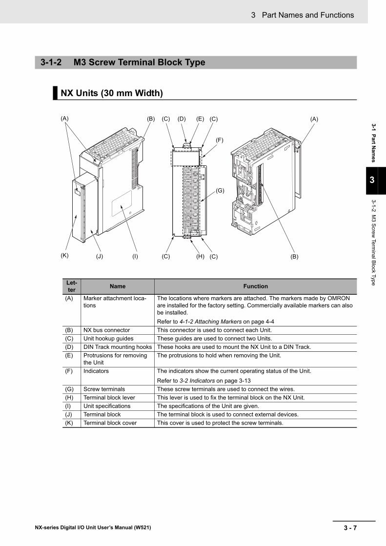
3 - 7
3 Part Names and Functions
NX-series Digital I/O Unit User’s Manual (W521)
3-1 Part Nam
es
3
3-1-2 M3 Screw
Terminal B
lock Type
3-1-2 M3 Screw Terminal Block Type
NX Units (30 mm Width)
Let-ter Name Function
(A) Marker attachment loca-tions
The locations where markers are attached. The markers made by OMRON are installed for the factory setting. Commercially available markers can also be installed.Refer to 4-1-2 Attaching Markers on page 4-4
(B) NX bus connector This connector is used to connect each Unit.(C) Unit hookup guides These guides are used to connect two Units.(D) DIN Track mounting hooks These hooks are used to mount the NX Unit to a DIN Track.(E) Protrusions for removing
the UnitThe protrusions to hold when removing the Unit.
(F) Indicators The indicators show the current operating status of the Unit.
Refer to 3-2 Indicators on page 3-13(G) Screw terminals These screw terminals are used to connect the wires.(H) Terminal block lever This lever is used to fix the terminal block on the NX Unit.(I) Unit specifications The specifications of the Unit are given.(J) Terminal block The terminal block is used to connect external devices.(K) Terminal block cover This cover is used to protect the screw terminals.
(C)(D)
(J) (I)
(G)
(F)
(C)(A) (E)
(C) (B)(C) (H)
(B)
(K)
(A)

3 Part Names and Functions
3 - 8 NX-series Digital I/O Unit User’s Manual (W521)
Units with MIL Connectors (1 Connector with 20 Terminals)
3-1-3 Connector Types
NX Units (30 mm Width)
Let-ter Name Function
(A) Marker attachment loca-tion
The locations where markers are attached. The markers made by OMRON are installed for the factory setting. Commercially available markers can also be installed.Refer to 4-1-2 Attaching Markers on page 4-4.
(B) NX bus connector This connector is used to connect each Unit.(C) Unit hookup guides These guides are used to connect two Units.(D) DIN Track mounting hooks These hooks are used to mount the NX Unit to a DIN Track.(E) Protrusions for removing
the UnitThe protrusions to hold when removing the Unit.
(F) Indicators The indicators show the current operating status of the Unit.
Refer to 3-2 Indicators on page 3-13.(G) Connectors The connectors are used to connect to external devices.(H) Unit specifications The specifications of the Unit are given.
(C)(E)(C)
(C)(D)
(H)
(G)
(F)
(C)(A) (E)(B) (B)

3 - 9
3 Part Names and Functions
NX-series Digital I/O Unit User’s Manual (W521)
3-1 Part Nam
es
3
3-1-3 Connector Types
Units with MIL Connectors (1 Connector with 40 Terminals)
Let-ter Name Function
(A) Marker attachment loca-tion
The locations where markers are attached. The markers made by OMRON are installed for the factory setting. Commercially available markers can also be installed.Refer to 4-1-2 Attaching Markers on page 4-4.
(B) NX bus connector This connector is used to connect each Unit.(C) Unit hookup guides These guides are used to connect two Units.(D) DIN Track mounting hooks These hooks are used to mount the NX Unit to a DIN Track.(E) Protrusions for removing
the UnitThe protrusions to hold when removing the Unit.
(F) Indicators The indicators show the current operating status of the Unit.
Refer to 3-2 Indicators on page 3-13.(G) Connectors The connectors are used to connect to external devices.(H) Unit specifications The specifications of the Unit are given.
(C)(E)(C)
(C)(D)
(H)
(G)
(F)
(C)(A) (E)(B) (B)

3 Part Names and Functions
3 - 10 NX-series Digital I/O Unit User’s Manual (W521)
Units with MIL Connectors (2 Connectors with 20 Terminals)
Let-ter Name Function
(A) Marker attachment loca-tion
The locations where markers are attached. The markers made by OMRON are installed for the factory setting. Commercially available markers can also be installed.Refer to 4-1-2 Attaching Markers on page 4-4.
(B) NX bus connector This connector is used to connect each Unit.(C) Unit hookup guides These guides are used to connect two Units.(D) DIN Track mounting hooks These hooks are used to mount the NX Unit to a DIN Track.(E) Protrusions for removing
the UnitThe protrusions to hold when removing the Unit.
(F) Indicators The indicators show the current operating status of the Unit.
Refer to 3-2 Indicators on page 3-13.(G) Connectors The connectors are used to connect to external devices.(H) Unit specifications The specifications of the Unit are given.
(C)(E)(C)
(C)(D)
(H)
(G)
(F)
(C)(A) (E)(B) (B)

3 - 11
3 Part Names and Functions
NX-series Digital I/O Unit User’s Manual (W521)
3-1 Part Nam
es
3
3-1-3 Connector Types
Units with Fujitsu Connectors (1 Connector with 40 Terminals)
Let-ter Name Function
(A) Marker attachment loca-tion
The locations where markers are attached. The markers made by OMRON are installed for the factory setting. Commercially available markers can also be installed.Refer to 4-1-2 Attaching Markers on page 4-4.
(B) NX bus connector This connector is used to connect each Unit.(C) Unit hookup guides These guides are used to connect two Units.(D) DIN Track mounting hooks These hooks are used to mount the NX Unit to a DIN Track.(E) Protrusions for removing
the UnitThe protrusions to hold when removing the Unit.
(F) Indicators The indicators show the current operating status of the Unit.
Refer to 3-2 Indicators on page 3-13.(G) Connectors The connectors are used to connect to external devices.(H) Unit specifications The specifications of the Unit are given.
(C)(E)(C)
(C)(D)
(H)
(G)
(F)
(C)(A) (E)(B) (B)

3 Part Names and Functions
3 - 12 NX-series Digital I/O Unit User’s Manual (W521)
Units with Fujitsu Connectors (2 Connectors with 24 Terminals)
Let-ter Name Function
(A) Marker attachment loca-tion
The locations where markers are attached. The markers made by OMRON are installed for the factory setting. Commercially available markers can also be installed.Refer to 4-1-2 Attaching Markers on page 4-4.
(B) NX bus connector This connector is used to connect each Unit.(C) Unit hookup guides These guides are used to connect two Units.(D) DIN Track mounting hooks These hooks are used to mount the NX Unit to a DIN Track.(E) Protrusions for removing
the UnitThe protrusions to hold when removing the Unit.
(F) Indicators The indicators show the current operating status of the Unit.
Refer to 3-2 Indicators on page 3-13.(G) Connectors The connectors are used to connect to external devices.(H) Unit specifications The specifications of the Unit are given.
(C)(E)(C)
(C)(D)
(H)
(G)
(F)
(C)(A) (E)(B) (B)

3 - 13
3 Part Names and Functions
NX-series Digital I/O Unit User’s Manual (W521)
3-2 Indicators
3
3-2 Indicators
There are the indicators to show the current operating status of the Unit or the signal I/O status on the Digital I/O Units.
The following indicator patterns are available depending on width of the Unit and the number of I/O points.
NX Units (12 mm Width)
NX Units (24 mm Width)
2-point type 4-point type 8-point type 16-point type
(A)
(B)
(A)
(B)
8-point type

3 Part Names and Functions
3 - 14 NX-series Digital I/O Unit User’s Manual (W521)
NX Units (30 mm Width)
The following section describes the specifications of each indicator.
Let-ter Name Function
(A) Model number indications The model numbers of the NX Unit are displayed.(Example) "ID3317" in the case of NX-ID3317
The NX Units are separated in the following color depending on the type of inputs and outputs.• Digital Input Unit: Orange• Digital Output Unit: Yellow• Digital Mixed I/O Unit: White
(B) Indicators The indicators show the current operating status of the NX Unit or the signal I/O status.
16-point type
16-point + 16-point type (Mixed I/O Units)
32-point type
(A)
(B)

3 - 15
3 Part Names and Functions
NX-series Digital I/O Unit User’s Manual (W521)
3-2 Indicators
3
3-2-1 TS Indicator
The meanings of light statuses are described as follows:
3-2-1 TS Indicator
Color Status DescriptionGreen Lit • The Unit is operating normally.
• The Unit is ready for I/O refreshing.
• I/O checking is operating.*1
*1. Refer to the manual for the Communications Coupler Unit for the status of the indicator on the Communications Coupler Units when I/O checking is in progress.
Flashing at 2-s intervals.
• Initializing• Restarting is in progress for the Unit.• Downloading
Red Lit A hardware failure, WDT error, or other fatal error that is common to all I/O Units occurred.
Flashing at 1-s intervals.
A communications error or other NX bus-related error that is common to all I/O Units occurred.
--- Not lit • No Unit power supply• Restarting is in progress for the Unit.• Waiting for initialization to start
This indicator shows the current status of the Digital I/O Unit and its communications status with the CPU Unit or with the Communications Coupler Unit.

3 Part Names and Functions
3 - 16 NX-series Digital I/O Unit User’s Manual (W521)
3-2-2 IN/OUT Indicator
Color Status DescriptionYellow Lit Digital I/O is ON
--- Not lit Digital I/O is OFF
This indicator shows the signal I/O status of each terminal of the Digital I/O Units.
For Digital Mixed I/O Units, the indicator shows as follows.
OUT indicator
IN indicator

4 - 1
4
NX-series Digital I/O Unit User’s Manual (W521)
This section describes how to install the NX Units, the types of power supplies provided to the NX Units and wiring methods, and how to wire the NX Units.
4-1 Installing NX Units . . . . . . . . . . . . . . . . . . . . . . . . . . . . . . . . . . . . . . . . . . . . . 4-24-1-1 Installing NX Units . . . . . . . . . . . . . . . . . . . . . . . . . . . . . . . . . . . . . . . . . . . . . . . 4-24-1-2 Attaching Markers . . . . . . . . . . . . . . . . . . . . . . . . . . . . . . . . . . . . . . . . . . . . . . . 4-44-1-3 Removing NX Units . . . . . . . . . . . . . . . . . . . . . . . . . . . . . . . . . . . . . . . . . . . . . . 4-64-1-4 Installation Orientation . . . . . . . . . . . . . . . . . . . . . . . . . . . . . . . . . . . . . . . . . . . 4-7
4-2 Power Supply Types and Wiring . . . . . . . . . . . . . . . . . . . . . . . . . . . . . . . . . . 4-94-2-1 Applications of I/O Power Supply and Supply Methods . . . . . . . . . . . . . . . . . . 4-94-2-2 Calculating the Total Current Consumption from I/O Power Supply . . . . . . . . .4-11
4-3 Wiring the Terminals . . . . . . . . . . . . . . . . . . . . . . . . . . . . . . . . . . . . . . . . . . 4-124-3-1 Wiring to the Screwless Clamping Terminal Block . . . . . . . . . . . . . . . . . . . . . 4-124-3-2 Wiring to M3 Screw Terminal Block . . . . . . . . . . . . . . . . . . . . . . . . . . . . . . . . 4-314-3-3 Wiring to MIL/Fujitsu Connectors . . . . . . . . . . . . . . . . . . . . . . . . . . . . . . . . . . 4-354-3-4 Checking the Wiring . . . . . . . . . . . . . . . . . . . . . . . . . . . . . . . . . . . . . . . . . . . . 4-39
4-4 Wiring Examples . . . . . . . . . . . . . . . . . . . . . . . . . . . . . . . . . . . . . . . . . . . . . 4-404-4-1 Wiring the Input Units . . . . . . . . . . . . . . . . . . . . . . . . . . . . . . . . . . . . . . . . . . . 4-404-4-2 Precautions when Wiring to the Output Units . . . . . . . . . . . . . . . . . . . . . . . . . 4-52
Installation and Wiring

4 Installation and Wiring
4 - 2 NX-series Digital I/O Unit User’s Manual (W521)
4-1 Installing NX Units
This section describes how to install NX Units.
Refer to the user's manual for the CPU Unit or Communications Coupler Unit to which NX Units areconnected for information on preparations of installation and installation in a control panel.
This section describes how to mount two NX Units to each other.
Always turn OFF the power supply before you mount NX Units.
Always mount NX Units one at a time. If you attempt to mount multiple NX Units that are already con-nected together, the connections between the NX Units may separate from each other and fall.
Precautions for Safe Use
• Do not apply labels or tape on the NX Units. When the Unit is installed or removed, adhesive or scrap may adhere to the pins of the NX bus connector, which may cause malfunctions.
• Do not touch the pins in the NX bus connector on the Unit. Dirt may adhere to the pins in the NX bus connector, which may result in malfunctions.
• Do not write on an NX Unit with ink within the restricted region that is shown in the following figure. Also do not get this area dirty. When the Unit is installed or removed, ink or dirt may adhere to the pins in the NX bus connector, which may result in malfunctions in the CPU Rack or the Slave Terminal. Refer to the user’s manual for the connected CPU Unit or Communications Coupler Unit for the restricted region of CPU Unit and Communications Coupler Unit.
4-1-1 Installing NX Units
Example: NX Unit (12 mm width)
NG NG
Restricted region (shaded
portion)

4 - 3
4 Installation and Wiring
NX-series Digital I/O Unit User’s Manual (W521)
4-1 Installing NX U
nits
4
4-1-1 Installing NX
Units
Precautions for Correct Use
• When you install an NX Unit, do not touch or bump the pins in the NX bus connector.• When you handle an NX Unit, be careful not to apply any stress to the pins in the NX bus
connector. If you install an NX Unit and turns ON the power supply when the pins in the NX bus connector are deformed, a contact defect may cause malfunctions.
1 From the front of the previously mounted NX Unit, engage the Unit hookup guides on a new Unit with the Unit hookup guides on the previously mounted NX Unit.
2 Slide the NX Unit in on the hookup guides.
3 Press the NX Unit with a certain amount of force against the DIN Track until you hear the DIN Track mounting hook lock into place.
When you mount the NX Unit, it is not necessary to release the DIN track mounting hook on the NX Unit.
After you mount the NX Unit, make sure that it is locked to the DIN Track.
Unit hookup guides
Unit hookup guides

4 Installation and Wiring
4 - 4 NX-series Digital I/O Unit User’s Manual (W521)
Additional Information
• Normally, it is not necessary to release the DIN track mounting hook when you mount the NX Unit. However, if you mount the NX Unit on a DIN Track that is not a recommended DIN Track, the DIN track mounting hook may not lock correctly. If that happens, first unlock the DIN track mounting hook, mount the NX Unit to the DIN Track, then lock the DIN track mount-ing hook.
• Refer to the user's manual for the CPU Unit to which NX Units can be connected for informa-tion on how to mount the CPU Unit, and how to mount NX Units to the CPU Unit.
• Refer to the user's manual for the Communications Coupler Unit for information on how to mount the Communications Coupler Unit, and how to mount the NX Unit to the Communica-tions Coupler Unit.
You can attach markers to the NX Units to identify them.
The plastic markers made by OMRON are installed for the factory setting. The ID information can bewritten on them.
Commercially available markers can also be installed.
Replace the markers made by OMRON if you use commercially available markers now.
The marker attachment locations vary depending on the type of the external connection terminals onthe NX Units.
4-1-2 Attaching Markers
External connection terminals on NX Units Marker attachment locationScrewless clamping terminal block NX Unit and terminal blockM3 screw terminal blockMIL connector NX Unit onlyFujitsu connector
A marker that is attached to the NX Unit
A marker that is attached to the terminal block

4 - 5
4 Installation and Wiring
NX-series Digital I/O Unit User’s Manual (W521)
4-1 Installing NX U
nits
4
4-1-2 Attaching M
arkers
Installation MethodInsert the protrusions on the markers into the marker attachment locations.
Commercially Available MarkersCommercially available markers are made of plastic and can be printed on with a special printer.
To use commercially available markers, purchase the following products.
The markers made by OMRON cannot be printed on with commercially available special printers.
Product nameModel number
Manufactured by Phoenix Contact Manufactured by WeidmullerMarkers UC1-TMF8 DEK 5/8Special marker printer UM EN BLUEMARK X1 PrintJet PRO
Marker attachment location
Marker
Screwless clamping terminal blockNX Unit M3 screw
terminal block
Marker attachment location
Marker Marker
Terminal block cover
Marker attachment location

4 Installation and Wiring
4 - 6 NX-series Digital I/O Unit User’s Manual (W521)
Precautions for Safe Use
Always turn OFF the Unit power supply and I/O power supply before you remove the NX Unit.
1 Use a flat-blade screwdriver to pull up the DIN Track mounting hook on the Unit to remove.
2 Put your fingers on the protrusions for removing multiple NX Units including the Unit to be removed, then pull out straight forward to remove.
4-1-3 Removing NX Units
Flat-blade screwdriverDIN track mounting hook
Protrusion for removing the Unit
Protrusion for removing the Unit

4 - 7
4 Installation and Wiring
NX-series Digital I/O Unit User’s Manual (W521)
4-1 Installing NX U
nits
4
4-1-4 Installation Orientation
Precautions for Correct Use
• When removing an NX Unit, remove multiple Units together which include the one you want to remove. If you attempt to remove only one Unit, it is stuck and hard to pull out.
• Do not unlock the DIN track mounting hooks on all of the NX Units at the same time. If you unlock the DIN Track mounting hooks on all of the NX Units at the same time, all of the Units may come off.
The following explains the installation orientation for each NX Unit connection destination.
Orientation is possible only in the upright installation orientation.
However, there are restrictions on the specifications depending on the NX Units to be used.
Refer to the user's manuals for the NX Units and System Units that you will use for details on restric-tions.
4-1-4 Installation Orientation
Installation Orientation in the Case of a CPU Unit
Upper
Lower

4 Installation and Wiring
4 - 8 NX-series Digital I/O Unit User’s Manual (W521)
Orientation is possible in the following six directions.
(A) is the upright orientation and (B) to (F) are other orientations.
However, there are restrictions on the installation orientation and restrictions to specifications that canresult from the Communications Coupler Units and NX Units that are used.
Refer to the user's manuals for the Communications Coupler Units, NX Units and System Units that youwill use for details on restrictions.
Precautions for Safe Use
For installation orientations (C) and (D) in the above figure, support the cables, e.g., with a duct, so that the End Plate on the bottom is not subjected to the weight of the cables. The weight of the cables may cause the bottom End Plate to slide downward so that the Slave Terminal is no longer secured to the DIN Track, which may cause malfunctions.
Installation Orientation in the Case of a Slave Terminal
(A)
(B)
(E) Upper
Lower
(C)
(F)
(D)

4 - 9
4 Installation and Wiring
NX-series Digital I/O Unit User’s Manual (W521)
4-2 Power Supply Types and W
iring
4
4-2-1 Applications of I/O
Pow
er Supply and Supply M
ethods
4-2 Power Supply Types and Wiring
There are the following two types of power supplies that supply power to the NX Units.
The method for supplying power to the NX Units and the wiring method depend on the specifications for the CPU Unit to which NX Units are connected or the specifications for the Slave Terminal. Refer to Designing the Power Supply System or Wiring, which are described both in the hardware user’s manual for the CPU Unit to which NX Units are connected and user’s manual for the Communications Coupler Unit, for details on the method for supplying power to the NX Units and the wiring method.
The subsequent sections describe the applications of I/O power supply for the Digital I/O Units and sup-ply methods, and how to calculate the total current consumption from the I/O power supply.
The applications of I/O power supply and supply methods for the Digital I/O Units are given as follows:
The I/O power supply is used for the following applications.• I/O circuits operations in the Digital I/O Units• Input current in a Digital Input Unit• Load current of the external load of a Digital Output Unit• Power supply for the connected external devices
This power is supplied by one of the following two methods. Refer to A-1 Data Sheet on page A-2 for the supply method of each NX Unit.
Supply from the NX BusThis power is supplied through the NX bus connectors by connecting an I/O power supply to the I/O power supply terminals on the Communications Coupler Unit or Additional I/O Power Supply Unit.
For the Units to which I/O power supply is provided by a CPU Rack, refer to Designing the Power Supply System or Wiring in the hardware user’s manual for the CPU Unit to which NX Units are con-nected.
For the Units to which I/O power supply is provided by a Slave Terminal, refer to Designing the Power Supply System or Wiring in the user's manual for the Communications Coupler Unit to be connected.
Power supply name DescriptionNX Unit power supply This power supply is used for operating the NX Units.I/O power supply This power supply is used for driving the I/O circuits of the NX Units and for the con-
nected external devices.
4-2-1 Applications of I/O Power Supply and Supply Methods
Applications of I/O Power Supply
I/O Power Supply Method

4 Installation and Wiring
4 - 10 NX-series Digital I/O Unit User’s Manual (W521)
Supply from External SourceThis power is supplied to the Units from an external source.
I/O power is supplied by connecting an I/O power supply to the I/O power supply terminals on the Units.
Additional Information
Power Supply-related Units for the NX-seriesThe following three NX-series Units are related to power supply.• Additional NX Unit Power Supply Unit• Additional I/O Power Supply Unit• I/O Power Supply Connection Unit
Refer to the NX-series System Unit User’s Manual (Cat. No. W523) for the specifications of these Units.
For a complete list of the latest power supply Units in the NX Series, refer to the product catalog or OMRON websites, or contact your OMRON representatives.

4 - 11
4 Installation and Wiring
NX-series Digital I/O Unit User’s Manual (W521)
4-2 Power Supply Types and W
iring
4
4-2-2 Calculating the Total C
urrent Consum
ption from I/O
Pow
er Supply
The total current consumption of I/O power supplied from the NX bus must be within the range of the maximum I/O power supply current of the Communications Coupler Unit or the Additional I/O Power Supply Unit. However, for a CPU Rack, the specification for the maximum I/O power supply current is restricted regardless of the model of the Additional I/O Power Supply Unit. Refer to the hardware user’s manual for the CPU Unit to which NX Units are connected for information on the restrictions for the CPU Rack.
To confirm this and to calculate the I/O power supply capacity, calculate the total current consumption from I/O power supply from the NX bus.
The total current consumption from I/O power supply from the NX bus is the total sum of current con-sumption from I/O power supply of the NX Unit that supplies the I/O power from the NX bus, the current consumption of each applicable I/O circuit, and current consumption of any connected external devices.
Note that the current consumption from I/O power supply indicated in the data sheet for each Unit type does not include the load current of any external connection load and current consumption of any con-nected external devices.
The total current consumption from I/O power supply of the Digital I/O Units is calculated as follows.
Total Current Consumption from I/O Power Supply of the Digital Input Units= (Current consumption from I/O power supply of the Digital Input Units) + (Input current of the Digi-tal Input Units × Number of input points used) + (Total current consumption of connected external devices)
Total Current Consumption from I/O Power Supply of the Digital Output Units= (Current consumption from I/O power supply of the Digital Output Units) + (Total load current of connection load) + (Total current consumption of connected external devices)
Refer to A-1 Data Sheet on page A-2 for the current consumption from I/O power supply for each Digital I/O Unit model and input current for each Digital Input Unit model.
There are no above confirmations if you use the NX Unit that supplies the I/O power from external source.
Use the total current consumption from I/O power supply from external source and the total current con-sumption from the I/O power supply from the above NX bus together to calculate the I/O power supply capacity.
Precautions for Safe Use
Use the I/O power supply current for the CPU Rack of the NX-series NX1P2 CPU Unit at 4 A or less. Using the currents that are outside of the specifications may cause failure or damage.
4-2-2 Calculating the Total Current Consumption from I/O Power Sup-ply

4 Installation and Wiring
4 - 12 NX-series Digital I/O Unit User’s Manual (W521)
4-3 Wiring the Terminals
This section describes how to wire the terminals on the Digital I/O Units.
This section describes how to connect wires to the screwless clamping terminal block, the installation and removing methods, and functions for preventing incorrect attachment.
You can connect ferrules that are attached to the twisted wires to the screwless clamping terminal block. You can also connect the twisted wires or the solid wires to the screwless clamping terminal block. If you connect the ferrules, all you need to do to connect the wires is to insert the ferrules into the terminal holes.
The terminals to be wired are as follows.
• I/O power supply terminals• I/O terminals
Make sure that the voltages and currents that are input to the Units and slaves are within the speci-fied ranges.
Inputting voltages or currents that are outside of the specified ranges may cause accidents or fire.
Be sure that all terminal screws and cable connector screws are tightened to the torque specified in the relevant manuals. The loose screws may result in fire or malfunction.
4-3-1 Wiring to the Screwless Clamping Terminal Block
Wiring Terminals
WARNING
Caution

4 - 13
4 Installation and Wiring
NX-series Digital I/O Unit User’s Manual (W521)
4-3 Wiring the Term
inals
4
4-3-1 Wiring to the S
crewless C
lamping Term
inal Block
The wires that you can connect to the screwless clamping terminal block are twisted wires, solid wires, and ferrules that are attached to the twisted wires. The following section describes the dimensions and processed methods for applicable wires.
Dimensions of Wires Connected to the Terminal BlockThe dimensions of wires that you can connect into the terminal holes of the screwless clamping ter-minal block are as in the figure below.
Process the applicable wires that are specified in the following description to apply the dimensions.
Applicable Wires
1.6 mm max. (Terminals other than ground terminals)2.0 mm max. (Ground terminals)
2.4 mm max. (Terminals other than ground terminals)2.7 mm max. (Ground terminals)

4 Installation and Wiring
4 - 14 NX-series Digital I/O Unit User’s Manual (W521)
Using FerrulesIf you use ferrules, attach the twisted wires to them.
Observe the application instructions for your ferrules for the wire stripping length when attaching fer-rules.
Always use plated one-pin ferrules. Do not use unplated ferrules or two-pin ferrules.
The applicable ferrules, wires, and crimping tools are listed in the following table.
When you use any ferrules other than those in the above table, crimp them to the twisted wires so that the following processed dimensions are achieved.
Terminal types
Manufac-turer
Ferrule model
Applica-ble wire
(mm2 (AWG))
Crimping tool
Terminals other than ground ter-minals
Phoenix Contact
AI0,34-8 0.34 (#22) Phoenix Contact (The figure in parentheses is the applicable wire size.)
CRIMPFOX 6 (0.25 to 6 mm2, AWG24 to 10)
AI0,5-8 0.5 (#20)AI0,5-10AI0,75-8 0.75 (#18)AI0,75-10AI1,0-8 1.0 (#18)AI1,0-10AI1,5-8 1.5 (#16)AI1,5-10
Ground ter-minals
AI2,5-10 2.0 *1
*1. Some AWG14 wires exceed 2.0 mm2 and cannot be used in the screwless clamping terminal block.
Terminals other than ground ter-minals
Weidmuller H0.14/12 0.14 (#26) Weidmuller (The figure in parentheses is the appli-cable wire size.)
PZ6 Roto (0.14 to 6 mm2, AWG26 to 10)
H0.25/12 0.25 (#24)H0.34/12 0.34 (#22)H0.5/14 0.5 (#20)H0.5/16H0.75/14 0.75 (#18)H0.75/16H1.0/14 1.0 (#18)H1.0/16H1.5/14 1.5 (#16)H1.5/16
8 to 10 mm
2.4 mm max. (Terminals other than ground terminals)2.7 mm max. (Ground terminals)
1.6 mm max. (Terminals other than ground terminals)2.0 mm max. (Ground terminals)
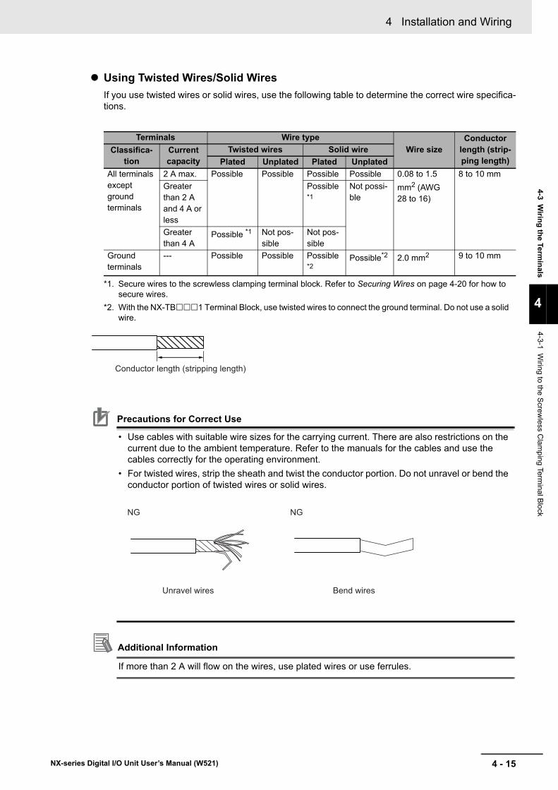
4 - 15
4 Installation and Wiring
NX-series Digital I/O Unit User’s Manual (W521)
4-3 Wiring the Term
inals
4
4-3-1 Wiring to the S
crewless C
lamping Term
inal Block
Using Twisted Wires/Solid WiresIf you use twisted wires or solid wires, use the following table to determine the correct wire specifica-tions.
Precautions for Correct Use
• Use cables with suitable wire sizes for the carrying current. There are also restrictions on the current due to the ambient temperature. Refer to the manuals for the cables and use the cables correctly for the operating environment.
• For twisted wires, strip the sheath and twist the conductor portion. Do not unravel or bend the conductor portion of twisted wires or solid wires.
Additional Information
If more than 2 A will flow on the wires, use plated wires or use ferrules.
Terminals Wire typeWire size
Conductor length (strip-ping length)
Classifica-tion
Current capacity
Twisted wires Solid wirePlated Unplated Plated Unplated
All terminals except ground terminals
2 A max. Possible Possible Possible Possible 0.08 to 1.5 mm2 (AWG 28 to 16)
8 to 10 mmGreater than 2 A and 4 A or less
Possible *1
Not possi-ble
Greater than 4 A
Possible *1
*1. Secure wires to the screwless clamping terminal block. Refer to Securing Wires on page 4-20 for how to secure wires.
Not pos-sible
Not pos-sible
Ground terminals
--- Possible Possible Possible *2
*2. With the NX-TB1 Terminal Block, use twisted wires to connect the ground terminal. Do not use a solid wire.
Possible*2 2.0 mm2 9 to 10 mm
Conductor length (stripping length)
Unravel wires Bend wires
NG NG

4 Installation and Wiring
4 - 16 NX-series Digital I/O Unit User’s Manual (W521)
This section describes how to connect and remove wires.
Terminal Block Parts and Names
Required ToolsUse a flat-blade screwdriver to connect and remove wires.
Use the following flat-blade screwdriver.
Recommended screwdriver
Connecting/Removing Wires
Model ManufacturerSZF 0-0,4×2,5 Phoenix Contact
Terminal hole
Release hole
2.5 mm0.4 mm
Front view
8 to 12°
Side view
2.5-mm dia.

4 - 17
4 Installation and Wiring
NX-series Digital I/O Unit User’s Manual (W521)
4-3 Wiring the Term
inals
4
4-3-1 Wiring to the S
crewless C
lamping Term
inal Block
Connecting FerrulesInsert the ferrule straight into the terminal hole.
It is not necessary to press a flat-blade screwdriver into the release hole.
After you make a connection, make sure that the ferrule is securely connected to the terminal block.
Connecting Twisted Wires/Solid WiresUse the following procedure to connect the twisted wires or solid wires to the terminal block.
1 Press a flat-blade screwdriver diagonally into the release hole.
Press at an angle of 10° to 15°.
If you press in the screwdriver correctly, you will feel the spring in the release hole.
Ferrule
1
10 to 15°
Release hole Flat-blade screwdriver
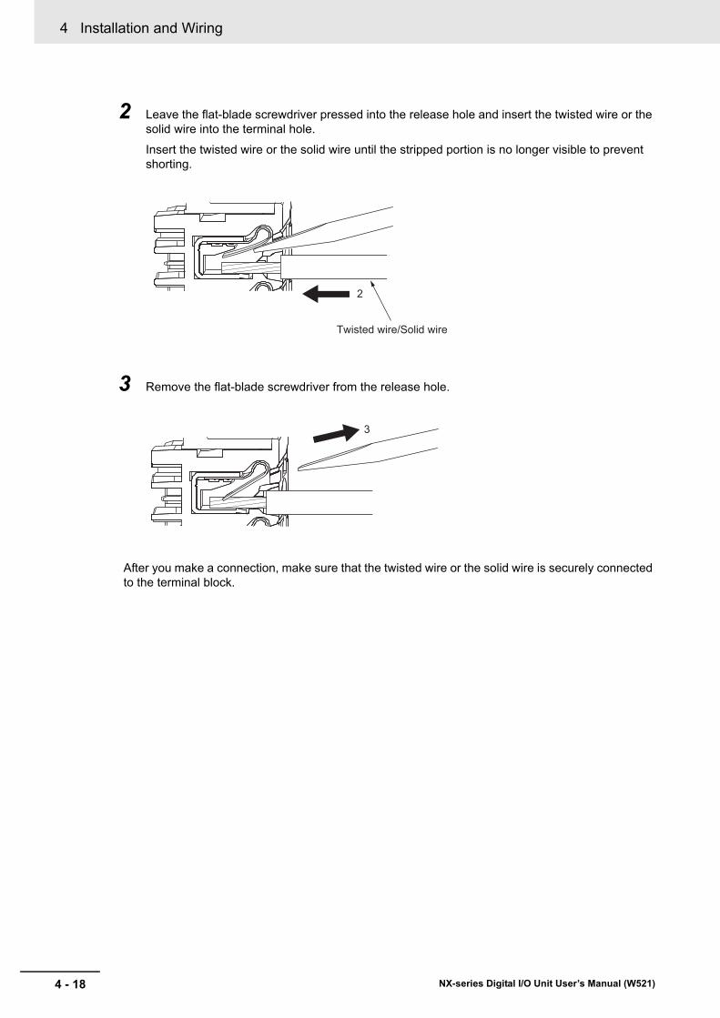
4 Installation and Wiring
4 - 18 NX-series Digital I/O Unit User’s Manual (W521)
2 Leave the flat-blade screwdriver pressed into the release hole and insert the twisted wire or the solid wire into the terminal hole.
Insert the twisted wire or the solid wire until the stripped portion is no longer visible to prevent shorting.
3 Remove the flat-blade screwdriver from the release hole.
After you make a connection, make sure that the twisted wire or the solid wire is securely connected to the terminal block.
2
Twisted wire/Solid wire
3

4 - 19
4 Installation and Wiring
NX-series Digital I/O Unit User’s Manual (W521)
4-3 Wiring the Term
inals
4
4-3-1 Wiring to the S
crewless C
lamping Term
inal Block
Precautions for Safe Use
• Do not press the flat-blade screwdriver straight into the release hole. Doing so may break the terminal block.
• When you insert a flat-blade screwdriver into a release hole, press it down with a force of 30 N max. Applying excessive force may damage the terminal block.
• Do not tilt or twist the flat-blade screwdriver while it is pressed into the release hole. Doing so may break the terminal block.
• Make sure that all wiring is correct.• Do not bend the cable forcibly. Doing so may sever the cable.
NG OK
NG NG

4 Installation and Wiring
4 - 20 NX-series Digital I/O Unit User’s Manual (W521)
Securing WiresIt is necessary to secure wires to the screwless clamping terminal block depending on the wire types that are used or the current flows on the wires.
The following table gives the necessity for securing wires.
Use the following procedure to secure the wires.
1 Prepare a cable tie.
A cable tie can be used with a width of 4 mm or less and a thickness of 1.5 mm or less.
Select a cable tie correctly for the operating environment.
2 Pass a cable tie through the hole for securing wires on the bottom of the screwless clamping ter-minal block.
TerminalsWire type
FerruleTwisted wires Solid wire
Classifica-tion
Current capacity Plated Unplated Plated Unplated
All terminals except ground terminals
2 A max. No No No No NoGreater than 2 A and 4 A or less
Not Possible Yes Not Possible
Greater than 4 A
Yes Not Possible
Ground terminals
--- No No No No
1.5 mm or less
4.0 mm or less
Hole for securing wires
Cable tie

4 - 21
4 Installation and Wiring
NX-series Digital I/O Unit User’s Manual (W521)
4-3 Wiring the Term
inals
4
4-3-1 Wiring to the S
crewless C
lamping Term
inal Block
3 Bundle the wires with a cable tie and secure them to the screwless clamping terminal block.
Secure wires within the range of 30 mm from the screwless clamping terminal block.
30 mm
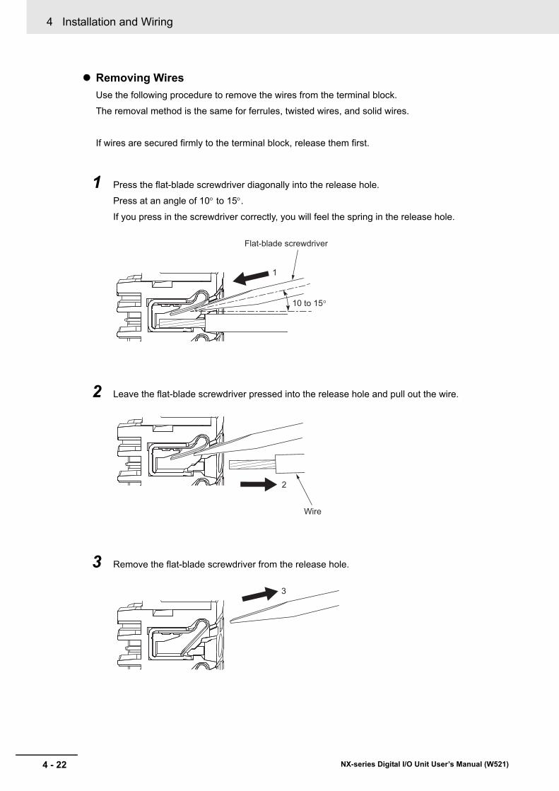
4 Installation and Wiring
4 - 22 NX-series Digital I/O Unit User’s Manual (W521)
Removing WiresUse the following procedure to remove the wires from the terminal block.
The removal method is the same for ferrules, twisted wires, and solid wires.
If wires are secured firmly to the terminal block, release them first.
1 Press the flat-blade screwdriver diagonally into the release hole.
Press at an angle of 10° to 15°.
If you press in the screwdriver correctly, you will feel the spring in the release hole.
2 Leave the flat-blade screwdriver pressed into the release hole and pull out the wire.
3 Remove the flat-blade screwdriver from the release hole.
1
10 to 15°
Flat-blade screwdriver
2
Wire
3

4 - 23
4 Installation and Wiring
NX-series Digital I/O Unit User’s Manual (W521)
4-3 Wiring the Term
inals
4
4-3-1 Wiring to the S
crewless C
lamping Term
inal Block
Precautions for Safe Use
• Do not press the flat-blade screwdriver straight into the release hole. Doing so may break the terminal block.
• When you insert a flat-blade screwdriver into a release hole, press it down with a force of 30 N max. Applying excessive force may damage the terminal block.
• Do not tilt or twist the flat-blade screwdriver while it is pressed into the release hole. Doing so may break the terminal block.
• Make sure that all wiring is correct.• Do not bend the cable forcibly. Doing so may sever the cable.
NG OK
NG NG

4 Installation and Wiring
4 - 24 NX-series Digital I/O Unit User’s Manual (W521)
1 Press the lock lever on the terminal block and pull out the top of the terminal block to remove it.
Removing a Terminal Block
Lock lever
Terminal block

4 - 25
4 Installation and Wiring
NX-series Digital I/O Unit User’s Manual (W521)
4-3 Wiring the Term
inals
4
4-3-1 Wiring to the S
crewless C
lamping Term
inal Block
1 Mount the terminal block hook on the guide at the bottom of the NX Unit, lift up the terminal block, and press in on the top of the terminal block until you hear it engage.
The terminal block will click into place on the Unit.
After you mount the terminal block, make sure that it is locked to the Unit.
Mount a terminal block that is applicable to each Unit model.
Refer to Applicable Terminal Blocks for Each Unit Model on page 3-6 for the applicable terminal blocks.
Attaching a Terminal Block
GuideHook

4 Installation and Wiring
4 - 26 NX-series Digital I/O Unit User’s Manual (W521)
In order to prevent unintentionally installing the wrong terminal block, you can limit the combination of a Unit and a terminal block.
Insert three Coding Pins (NX-AUX02) into three of the six incorrect attachment prevention holes on the Unit and on the terminal block. Insert these pins into positions so that they do not interfere with each other when the Unit and terminal block are connected to each other.
You can use these pins to create a combination in which the wrong terminal block cannot be attached because the pin patterns do not match.
Preventing Incorrect Attachment of Terminal Blocks
Terminal block
Unit
Cannot be attached.

4 - 27
4 Installation and Wiring
NX-series Digital I/O Unit User’s Manual (W521)
4-3 Wiring the Term
inals
4
4-3-1 Wiring to the S
crewless C
lamping Term
inal Block
Types of Coding PinsThere are two types of Coding Pins, both with their own unique shape: one for terminal blocks and one for Units.
Three pins come with each runner.
Use the following Coding Pins.
Name Model SpecificationCoding Pin NX-AUX02 For 10 Units
(Terminal block: 30 pins, Unit: 30 pins)
For terminal block For Unit
Coding Pins (Use this part.)
Runners
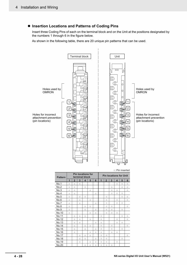
4 Installation and Wiring
4 - 28 NX-series Digital I/O Unit User’s Manual (W521)
Insertion Locations and Patterns of Coding PinsInsert three Coding Pins of each on the terminal block and on the Unit at the positions designated by the numbers 1 through 6 in the figure below.
As shown in the following table, there are 20 unique pin patterns that can be used.
Pin locations for terminal block
: Pin inserted
Terminal block Unit
1 2 3 4 5 6No.1 No.2 No.3 No.4 No.5 No.6 No.7 No.8 No.9 No.10
No.11 No.12 No.13 No.14 No.15 No.16 No.17 No.18 No.19 No.20
1 2 3 4 5 6
1
2
3
4
5
6
1
2
3
4
5
6
Holes used byOMRON
Holes for incorrectattachment prevention(pin locations)
Pin locations for UnitPattern
Holes used byOMRON
Holes for incorrectattachment prevention(pin locations)

4 - 29
4 Installation and Wiring
NX-series Digital I/O Unit User’s Manual (W521)
4-3 Wiring the Term
inals
4
4-3-1 Wiring to the S
crewless C
lamping Term
inal Block
To make the maximum of 20 patterns, purchase two sets of NX-AUX02 Pins. (One set for 10 Units.)
Precautions for Correct Use
• OMRON uses the holes other than No. 1 to 6 in the figure on the previous page. If you insert a Coding Pin into one of the holes used by OMRON on the terminal block side, this makes it impossible to mount the terminal block on a Unit.
• Do not use Coding Pins that have been attached and removed.
Inserting the Coding Pins
1 Hold the pins by the runner and insert a pin into one of the incorrect attachment prevention holes on the terminal block or on the Unit.
2 Rotate the runner to break off the Coding Pin.
Terminal block Unit
Terminal block

4 Installation and Wiring
4 - 30 NX-series Digital I/O Unit User’s Manual (W521)
Unit
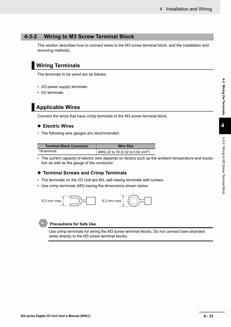
4 - 31
4 Installation and Wiring
NX-series Digital I/O Unit User’s Manual (W521)
4-3 Wiring the Term
inals
4
4-3-2 Wiring to M
3 Screw
Terminal B
lock
This section describes how to connect wires to the M3 screw terminal block, and the installation and removing methods.
The terminals to be wired are as follows.
• I/O power supply terminals• I/O terminals
Connect the wires that have crimp terminals to the M3 screw terminal block.
Electric Wires• The following wire gauges are recommended.
• The current capacity of electric wire depends on factors such as the ambient temperature and insula-tion as well as the gauge of the conductor.
Terminal Screws and Crimp Terminals• The terminals on the I/O Unit are M3, self-raising terminals with screws.• Use crimp terminals (M3) having the dimensions shown below.
Precautions for Safe Use
Use crimp terminals for wiring the M3 screw terminal blocks. Do not connect bare stranded wires directly to the M3 screw terminal blocks.
4-3-2 Wiring to M3 Screw Terminal Block
Wiring Terminals
Applicable Wires
Terminal Block Connector Wire Size18-terminal AWG 22 to 18 (0.32 to 0.82 mm2)
6.2 mm max. 6.2 mm max.

4 Installation and Wiring
4 - 32 NX-series Digital I/O Unit User’s Manual (W521)
• Make sure that all Units are connected properly.• Do not allow wire clippings, shavings, or other foreign material to enter any Unit during wiring.• Wire the Units so that they can be easily replaced.• Make sure that the I/O indicators are not covered by the wiring.• Do not place the wiring for I/O Units in the same duct or raceway as power lines. Inductive noise can
cause errors in operation.• Tighten the terminal screws to the torque of 0.5 N•m.
Connecting/Removing Wires
Screw (M3 screw with self-raising pressure plate)
17.5 mm

4 - 33
4 Installation and Wiring
NX-series Digital I/O Unit User’s Manual (W521)
4-3 Wiring the Term
inals
4
4-3-2 Wiring to M
3 Screw
Terminal B
lock
1 Release the lock of the terminal block.(1) Pull the terminal block cover forward to open the cover.(2) Pull the terminal block lever downward.
Support the NX Unit firmly while performing the operation of the terminal block lever.
2 Pull out the terminal block straight forward to remove.
Removing a Terminal Block
Terminal block cover Terminal block lever
(1) (2)

4 Installation and Wiring
4 - 34 NX-series Digital I/O Unit User’s Manual (W521)
1 Insert the terminal block straight into the NX Unit all the way.
2 Lock the terminal block.(1) Push in the terminal block lever upward.(2) Close the terminal block cover if it is still open.
Attaching a Terminal Block
Terminal block coverTerminal block lever
(1) (2)

4 - 35
4 Installation and Wiring
NX-series Digital I/O Unit User’s Manual (W521)
4-3 Wiring the Term
inals
4
4-3-3 Wiring to M
IL/Fujitsu Connectors
This section describes wiring for the Digital I/O Units with connectors.
Depending on the connector, the following methods are used to connect the Digital I/O Units with con-nectors to external I/O devices.• Use an OMRON Connecting Cable (equipped with a special connector) to connect to a terminal block
or relay terminal.• Use a special connector and make your own cable.
Precautions for Safe Use
• Do not apply voltages that exceed the rated value to any Input Unit.• Do not apply voltages or connect loads to the Output Units or slaves in excess of the maxi-
mum ratings.• Turn ON the power after checking the connector's wiring.• Do not pull the cable. Doing so will damage the cable.• Bending the cable too sharply can damage or break wiring in the cable.• If the external power supply has polarity, connect it with the correct polarity. If the polarity is
reversed, current may flow in the reverse direction and damage the connected devices regardless of the operation of the Unit.
Additional Information
The Digital I/O Units with 32 points and Fujitsu connectors have the same connector pin alloca-tions as the C200H High-density I/O Units, CS-series I/O Units with connectors and CJ-series I/O Units with connectors to make them compatible.
OMRON Connecting Cable can be used to connect Digital I/O Units with connectors to OMRON Con-nector-Terminal Block Conversion Units or to OMRON I/O Relay Terminals.
For details, refer to A-3 Connecting Connector-Terminal Block Conversion Units and I/O Relay Termi-nals on page A-102.
Connection Examples
4-3-3 Wiring to MIL/Fujitsu Connectors
Connecting to Connector-Terminal Block Conversion Units or I/O Relay Terminals
Connector-Terminal Block Conversion Unit
20 or 40 terminals
Connecting CableNX Unit
Connector-Terminal Block Conversion Unit
I/O Relay Terminal
Connecting Cable
NX Unit
I/O Relay Terminals

4 Installation and Wiring
4 - 36 NX-series Digital I/O Unit User’s Manual (W521)
Available ConnectorsUse the following connectors when assembling a connector and cable.
NX Units with MIL Connectors
Applicable Cable-side Connectors
NX Units with Fujitsu Connectors
Applicable Cable-side Connectors
Using User-made Cables with Connector
Model Specifications PinsNX-ID5142-5 DC Input Unit, 16 points 20NX-ID6142-5 DC Input Unit, 32 points 40NX-OD5121-5 Transistor Output Unit, 16 points 20NX-OD5256-5NX-OD6121-5 Transistor Output Unit, 32 points 40NX-OD6256-5NX-MD6121-5 DC Input/Transistor Output Units, 16 inputs, 16
outputs20 (× 2)
NX-MD6256-5
Connection Pins OMRON set DDK partsPressure-welded 40 XG4M-4030-T FRC5-A040-3TOS
20 XG4M-2030-T FRC5-A020-3TOSCrimped 40 XG5N-401 ---
20 XG5N-201 ---
Model Specifications PinsNX-ID6142-6 DC Input Unit, 32 points 40NX-OD6121-6 Transistor Output Unit, 32 pointsNX-MD6121-6 DC Input/Transistor Output Units, 16 inputs, 16 outputs 24 (× 2)
Connection Pins OMRON set Fujitsu partsSolder-type 40 C500-CE404 Socket: FCN-361J040-AU
Connector cover: FCN-360C040-J224 C500-CE241 Socket: FCN-361J024-AU
Connector cover: FCN-360C024-J2Crimped 40 C500-CE405 Socket: FCN-363J040
Connector cover: FCN-360C040-J2
Contacts: FCN-363J-AU24 C500-CE242 Socket: FCN-363J024
Connector cover: FCN-360C024-J2
Contacts: FCN-363J-AUPressure-welded 40 C500-CE403 FCN-367J040-AU/F
24 C500-CE243 FCN-367J024-AU/F

4 - 37
4 Installation and Wiring
NX-series Digital I/O Unit User’s Manual (W521)
4-3 Wiring the Term
inals
4
4-3-3 Wiring to M
IL/Fujitsu Connectors
Wire SizeWe recommend using cable with wire gauges of AWG 24 or AWG 28 (0.2 mm2 to 0.08 mm2). Use cable with external wire diameters of 1.61 mm max.
Wiring
NX Units with MIL Connectors
• Make sure that all Units are connected properly.• After the cable side connector is connected, close the lock lever on the NX Unit side connector sec-
tion to lock it. After you complete the wiring, make sure that the connector is locked.
NX Units with Fujitsu Connectors
1 Check that each Unit is installed securely.
Precautions for Correct Use
Do not force the cables.
2 When solder-type connectors are being used, be sure not to accidentally short adjacent termi-nals.
Cover the solder joint with heat-shrink tubing.
Solder-type connector
Heat-shrink tubingWire (0.2 to 0.13 mm2)
→

4 Installation and Wiring
4 - 38 NX-series Digital I/O Unit User’s Manual (W521)
3 Assemble the connector (purchased separately).
4 Mount the connector on the Digital I/O Unit and fix it in place with lock screws.
Tighten the connector lock screws to a torque of 0.2•m.
Nuts (3)
Socket
Connector coverSmall screws (3)
Nuts (2)
Cable bracket
Connector lock screws
Small screws (2)
Connector
Connector
Digital I/O UnitDigital I/O Unit
Connector lock screws

4 - 39
4 Installation and Wiring
NX-series Digital I/O Unit User’s Manual (W521)
4-3 Wiring the Term
inals
4
4-3-4 Checking the W
iring
Check the wiring by reading input data or writing output data from Slave Terminals using the Watch Tab Page of the Support Software.
For Input Units, you can turn ON/OFF the inputs from external devices that are connected to the target Units and monitor the results.
For Output Units, you can execute the I/O outputs of the target Units and check the operation of the connected external devices.
For details on monitoring and I/O output operations using the Support Software, refer to the operation manual for the Support Software that you are using.
Additional Information
• If you check the wiring for the Output Units that support output refreshing with specified time stamp, set the value of the Output Bit Time Stamp parameter to 0. At this time, the Out-put Units refresh outputs immediately and outputs are refreshed according to the output set values.
• In the Sysmac Studio, you can check the wiring from the I/O Map or Watch Tab Page. If you use the I/O Map, you can also monitor and perform forced refreshing even if the variables are not defined or the algorithms are not created. Therefore, you can easily check the wiring. Refer to the Sysmac Studio Version 1 Operation Manual (Cat. No. W504) for details on mon-itoring and forced refreshing operations.
• Some Communications Coupler Units support I/O checking that allows you to check wiring with only the Slave Terminal. Refer to the user's manual of the Communications Coupler Unit for detailed information on the support and functionality of I/O checking for your Communica-tions Coupler Unit.
4-3-4 Checking the Wiring

4 Installation and Wiring
4 - 40 NX-series Digital I/O Unit User’s Manual (W521)
4-4 Wiring Examples
This section gives some wiring examples for the Digital I/O Units and precautions for wiring.
NPN Type Input Units
This is the wiring for contact output type external devices.
This is the wiring for two-wire sensors.
4-4-1 Wiring the Input Units
Wiring to the DC Input Units (When I/O Power Is Supplied from the NX Bus)
IN
IOG
IOV
IOG
IOV
DC Input Unit
Communications Coupler Unit orAdditional I/O Power Supply Unit
Contact output
IN
IOG
IOV
IOG
IOV
Two-wire sensor
DC Input Unit
Communications Coupler Unit orAdditional I/O Power Supply Unit

4 - 41
4 Installation and Wiring
NX-series Digital I/O Unit User’s Manual (W521)
4-4 Wiring Exam
ples
4
4-4-1 Wiring the Input U
nits
This is the wiring for three-wire sensors.
PNP Type Input Units
This is the wiring for contact output type external devices.
IN
IOG
IOV
IOG
IOV
0V
Output
+
Three-wire sensor
DC Input Unit
Communications Coupler Unit orAdditional I/O Power Supply Unit
IOG
IOV
IOG
IOV
IN
Contact output
DC Input Unit
Communications Coupler Unit orAdditional I/O Power Supply Unit

4 Installation and Wiring
4 - 42 NX-series Digital I/O Unit User’s Manual (W521)
This is the wiring for two-wire sensors.
This is the wiring for three-wire sensors.
IOG
IOV
IOG
IOV
IN
Two-wire sensor
DC Input Unit
Communications Coupler Unit orAdditional I/O Power Supply Unit
IOG
IOV
IOG
IOV
IN
Three-wire sensor
0V
+
Output
DC Input Unit
Communications Coupler Unit orAdditional I/O Power Supply Unit

4 - 43
4 Installation and Wiring
NX-series Digital I/O Unit User’s Manual (W521)
4-4 Wiring Exam
ples
4
4-4-1 Wiring the Input U
nits
Precautions when Connecting a Two-wire DC SensorWhen a two-wire sensor is used with a DC Input Unit, check that the following conditions are met. Failure to meet these conditions may result in operating errors.
(a) Relation between ON voltage of the DC Input Unit and sensor residual voltage
The DC Input Unit cannot detect sensor output ON unless the following conditions are satisfied:
VON ≤ VCC - VR
The voltages related to the conditions for NPN type sensors are shown in the figure below.
The voltages related to the conditions for PNP type sensors are shown in the figure below.
VCC: Power supply voltage
VR: Sensor's output residual voltage
VON: ON voltage of DC Input Unit
IN
IOG
IOV
IOG
IOV
VR
VCC VON
Two-wire sensor
DC Input Unit
Communications Coupler Unit orAdditional I/O Power Supply Unit
IOG
IOV
IOG
IOV
IN
VR VCC
VON
Two-wire sensor
DC Input Unit
Communications Coupler Unit orAdditional I/O Power Supply Unit

4 Installation and Wiring
4 - 44 NX-series Digital I/O Unit User’s Manual (W521)
(b) Relation between input current to the DC Input Unit and sensor control output (load current)
The DC Input Unit cannot detect sensor output ON unless the following conditions are satisfied:
IOUT (min) ≤ Iin ≤ IOUT (max)
IOUT (min): Minimum value of load current
IOUT (max): Maximum value of load current
Use the following equation to calculate the input current of the resistance input.
Iin = (VCC - VR - 1.5 [internal residual voltage of DC Input Unit]) / RIN
Use the following equation to calculate the input current of the constant current input.
Iin = ION
Note For constant current input type Input Units, the input current does not increase linearly for the input volt-age. If you gradually raise the input voltage and once the input current reaches ION, the input current
does not increase and remains roughly constant even when the input voltage is raised.
When Iin is smaller than IOUT (min), connect a bleeder resistor R. The bleeder resistor constant can be calculated as follows: Select an appropriate bleeder resistor R so that both equations can be sat-isfied.
R ≤ (VCC - VR) / (IOUT (min) - ION)
Rated power W of bleeder resistor ≥ (VCC - VR)2 / R × 4 [allowable margin]

4 - 45
4 Installation and Wiring
NX-series Digital I/O Unit User’s Manual (W521)
4-4 Wiring Exam
ples
4
4-4-1 Wiring the Input U
nits
The voltages and currents related to the conditions for NPN type sensors are shown in the figure below.
The voltages and currents related to the conditions for PNP type sensors are shown in the figure below.
VCC: Power supply voltage
VR: Sensor's output residual voltage
IOUT: Sensor control output (load current)
ION: Input current of DC Input Unit (Input current when the rated voltage is applied)
R: Bleeder resistor
RIN: Input resistor of DC Input Unit
IN
IOG
IOV
IOG
IOV
VR
VCC R IinIOUTRIN
Two-wire sensor
DC Input Unit
Communications Coupler Unit orAdditional I/O Power Supply Unit
IOUT
IOG
IOV
IOG
IOV
IN
VR VCC
R
Iin
RIN
Two-wire sensor
DC Input Unit
Communications Coupler Unit orAdditional I/O Power Supply Unit

4 Installation and Wiring
4 - 46 NX-series Digital I/O Unit User’s Manual (W521)
(c) Relation between OFF current of the DC Input Unit and sensor leakage current
The DC Input Unit cannot detect sensor output OFF unless the following conditions are satisfied:
IOFF ≥ Ileak
When Ileak is greater than IOFF, connect a bleeder resistor R.
Use the following equation to calculate the bleeder resistance constant of the resistance input.
R ≤ RIN × VOFF / (Ileak × RIN - VOFF)
Use the following equation to calculate the bleeder resistance constant of the constant current input.
R ≤ (VOFF / IOFF) × VOFF / (Ileak × (VOFF / IOFF) - VOFF)
For both the resistance input and constant current input, use the following equation to calculate the rated power of bleeder resistor.
Rated power W of bleeder resistor ≥ (VCC - VR)2 / R × 4 [allowable margin]
The voltages and currents related to the conditions for NPN type sensors are shown in the figure below.
IN
IOG
IOV
IOG
IOV
VR
VCC R IOFFIleakRINVOFF
Two-wire sensor
DC Input Unit
Communications Coupler Unit orAdditional I/O Power Supply Unit
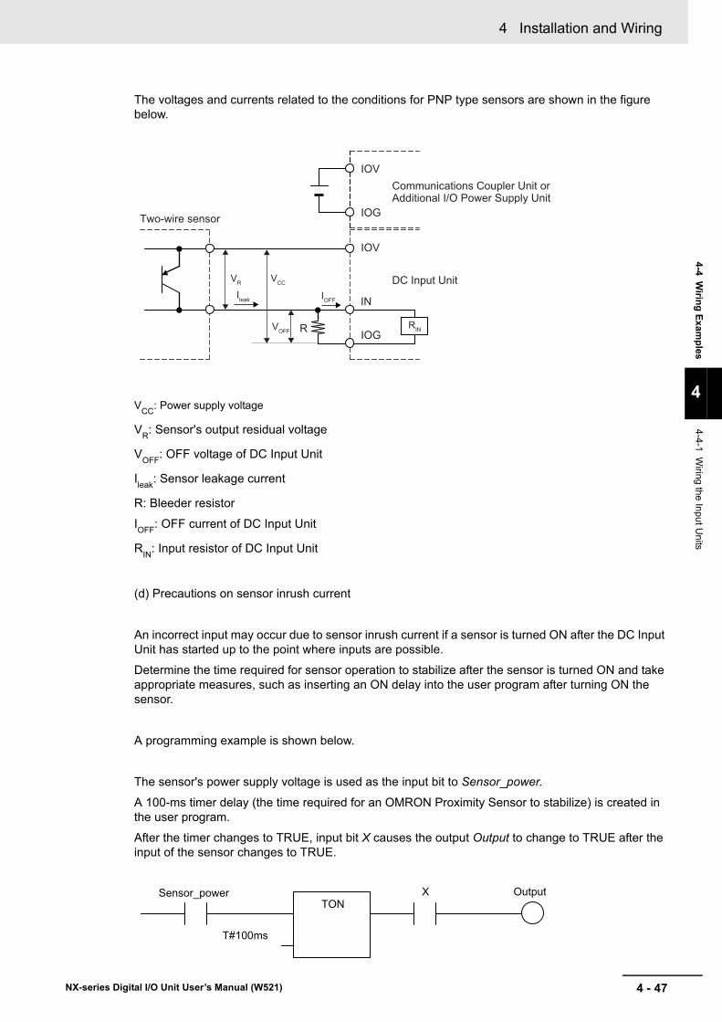
4 - 47
4 Installation and Wiring
NX-series Digital I/O Unit User’s Manual (W521)
4-4 Wiring Exam
ples
4
4-4-1 Wiring the Input U
nits
The voltages and currents related to the conditions for PNP type sensors are shown in the figure below.
VCC: Power supply voltage
VR: Sensor's output residual voltage
VOFF: OFF voltage of DC Input Unit
Ileak: Sensor leakage current
R: Bleeder resistor
IOFF: OFF current of DC Input Unit
RIN: Input resistor of DC Input Unit
(d) Precautions on sensor inrush current
An incorrect input may occur due to sensor inrush current if a sensor is turned ON after the DC Input Unit has started up to the point where inputs are possible.
Determine the time required for sensor operation to stabilize after the sensor is turned ON and take appropriate measures, such as inserting an ON delay into the user program after turning ON the sensor.
A programming example is shown below.
The sensor's power supply voltage is used as the input bit to Sensor_power.
A 100-ms timer delay (the time required for an OMRON Proximity Sensor to stabilize) is created in the user program.
After the timer changes to TRUE, input bit X causes the output Output to change to TRUE after the input of the sensor changes to TRUE.
Ileak
IOG
IOV
IOG
IOV
IN
VR VCC
R
IOFF
RINVOFF
Two-wire sensor
DC Input Unit
Communications Coupler Unit orAdditional I/O Power Supply Unit
TON
T#100ms
X Output Sensor_power

4 Installation and Wiring
4 - 48 NX-series Digital I/O Unit User’s Manual (W521)
Use the following information for reference when selecting or connecting input devices.
DC Input UnitsThe following types of DC input devices can be connected.
Wiring to the DC Input Units (When I/O Power Is Supplied from an External Source)
DC Input Unit
Output7 mA0 V
+DC Input Unit
Output
7 mA0 V
+Current regulator
+
IN
COM
DC Input Unit
DC Input Unit
DC Input Unit
Output7 mA0 V
+
Two-wire DC output
NPN open-collector output
DC Input Unit
COM
IN
Contact output
NPN current output
PNP current outputVoltage output
• The circuit below should NOT be used for I/O devices having a voltage output.
INOutput0 V
+
COM
Output
0 V
+
IN
COM
DC Input Unit+
ININ
COMCOM
IN
COM
SensorPowerSupply
SensorPowerSupply
SensorPowerSupply
SensorPowerSupply
SensorPowerSupply
SensorPowerSupply
4 - 49
4 Installation and Wiring
NX-series Digital I/O Unit User’s Manual (W521)
4-4 Wiring Exam
ples
4
4-4-1 Wiring the Input U
nits
Precautions when Connecting a Two-wire DC SensorWhen a two-wire sensor is used with a DC Input Unit, check that the following conditions are met. Failure to meet these conditions may result in operating errors.
(a) Relation between ON voltage of the DC Input Unit and sensor residual voltage
VON ≤ VCC - VR
(b) Relation between input current to the DC Input Unit and sensor control output (load current)
IOUT (min) ≤ ION ≤ IOUT (max)
ION = (VCC - VR - 1.5 [internal residual voltage of DC Input Unit]) / RIN
When ION is smaller than IOUT (min), connect a bleeder resistor R. The bleeder resistor constant can be calculated as follows:
R ≤ (VCC - VR) / (IOUT (min) - ION)
Power W of bleeder resistor ≥ (VCC - VR)2 / R × 4 [allowable margin]
VCC: Input voltage of DC Input Unit
VR: Sensor's output residual voltage
ION: Input current of DC Input Unit
IOUT: Sensor control output (load current)
RIN: Input resistor of DC Input Unit
(c) Relation between OFF current of the DC Input Unit and sensor leakage current
IOFF ≥ Ileak
When Ileak is greater than IOFF, connect a bleeder resistor R.
Use the following equation to calculate the bleeder resistance constant.
R ≤ RIN × VOFF / (Ileak × RIN - VOFF)
Power W of bleeder resistor ≥ (VCC - VR)2 / R × 4 [allowable margin]

4 Installation and Wiring
4 - 50 NX-series Digital I/O Unit User’s Manual (W521)
(d) Precautions on sensor inrush current
An incorrect input may occur due to sensor inrush current if a sensor is turned ON after the DC Input Unit has started up to the point where inputs are possible.
Determine the time required for sensor operation to stabilize after the sensor is turned ON and take appropriate measures, such as inserting an ON delay into the user program after turning ON the sensor.
A programming example is shown below.
The sensor's power supply voltage is used as the input bit to Sensor_power.
A 100-ms timer delay (the time required for an OMRON Proximity Sensor to stabilize) is created in the user program.
After the timer changes to TRUE, input bit X causes the output Output to change to TRUE after the input of the sensor changes to TRUE.
VCC: Power supply voltage VR: Sensor's output residual voltage
VON: ON voltage of DC Input Unit IOUT: Sensor control output (load current)
VOFF: OFF voltage of DC Input Unit Ileak: Sensor leakage current
ION: ON current of DC Input Unit R: Bleeder resistor
IOFF: OFF current of DC Input Unit
RIN: Input resistor of DC Input Unit
DC Input Unit
RVR
VCC
Two-wire sensor
RIN
TON
T#100ms
X Output Sensor_power
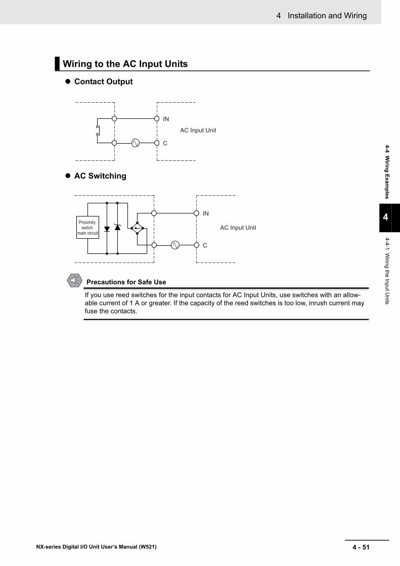
4 - 51
4 Installation and Wiring
NX-series Digital I/O Unit User’s Manual (W521)
4-4 Wiring Exam
ples
4
4-4-1 Wiring the Input U
nits
Contact Output
AC Switching
Precautions for Safe Use
If you use reed switches for the input contacts for AC Input Units, use switches with an allow-able current of 1 A or greater. If the capacity of the reed switches is too low, inrush current may fuse the contacts.
Wiring to the AC Input Units
C
IN
AC Input Unit
C
IN
AC Input UnitProximity
switch main circuit

4 Installation and Wiring
4 - 52 NX-series Digital I/O Unit User’s Manual (W521)
If a load connected to the output terminals is short-circuited, output components and printed circuit boards may be damaged. To guard against this, use the NX Units with load short-circuit protection.
When using the NX Units without load short-circuit protection, incorporate a protective fuse in the exter-nal circuit. Use a fuse with a capacity of around twice the rated output.
When connecting a transistor to an output device with a high inrush current (such as an incandescent lamp), steps must be taken to avoid damage to the output transistor.
Use either of the following methods to reduce the inrush current.
Countermeasure 1Draw about 1/3 of the current consumed by the load.
When I/O power is supplied from the NX bus, the method is as shown in the following figure.
When I/O power is supplied from an external source, the method is as shown in the following figure.
4-4-2 Precautions when Wiring to the Output Units
Output Short-circuit Protection
Inrush Current
IOG
IOV
IOG
IOV
Transistor Output UnitOUT
IOG
IOV
IOG
IOV
OUT
NPN type PNP type
L
L
Communications Coupler Unit or Additional I/O Power Supply Unit
Transistor Output Unit
Communications Coupler Unit or Additional I/O Power Supply Unit
OUT
COM
RTransistor Output Unit
NPN type PNP type
L+
OUT
COM
RTransistor Output Unit
L
+

4 - 53
4 Installation and Wiring
NX-series Digital I/O Unit User’s Manual (W521)
4-4 Wiring Exam
ples
4
4-4-2 Precautions w
hen Wiring to the O
utput Units
Countermeasure 2Mount a limiting resistor.
When I/O power is supplied from the NX bus, the method is as shown in the following figure.
When I/O power is supplied from an external source, the method is as shown in the following figure.
In countermeasure 1, the current consumption from I/O power supply is increased although the voltage supplied to the load L is not decreased.
In countermeasure 2, the voltage supplied to the load L is decreased although the current consumption from I/O power supply is not increased.
Select the appropriate countermeasures according to the operating conditions.
IOG
IOV
IOG
IOV
OUT
IOG
IOV
IOG
IOV
OUT
NPN type PNP type
L
LTransistor Output Unit
Communications Coupler Unit or Additional I/O Power Supply Unit
Transistor Output Unit
Communications Coupler Unit or Additional I/O Power Supply Unit
ROUT
COM
+Transistor Output Unit
NPN type PNP type
L
OUT
COM+
Transistor Output Unit
LR

4 Installation and Wiring
4 - 54 NX-series Digital I/O Unit User’s Manual (W521)

5 - 1
5
NX-series Digital I/O Unit User’s Manual (W521)
This section describes the types and functions of I/O refreshing for the NX Units.
5-1 I/O Refreshing . . . . . . . . . . . . . . . . . . . . . . . . . . . . . . . . . . . . . . . . . . . . . . . . . 5-25-1-1 I/O Refreshing from CPU Units to NX Units . . . . . . . . . . . . . . . . . . . . . . . . . . . 5-25-1-2 I/O Refreshing from CPU Units or Industrial PCs to Slave Terminal . . . . . . . . . 5-3
5-2 I/O Refreshing Methods . . . . . . . . . . . . . . . . . . . . . . . . . . . . . . . . . . . . . . . . . 5-55-2-1 Types of I/O Refreshing Methods . . . . . . . . . . . . . . . . . . . . . . . . . . . . . . . . . . . 5-55-2-2 Setting the I/O Refreshing Methods . . . . . . . . . . . . . . . . . . . . . . . . . . . . . . . . . 5-75-2-3 Selecting NX Units . . . . . . . . . . . . . . . . . . . . . . . . . . . . . . . . . . . . . . . . . . . . . . 5-85-2-4 Free-Run Refreshing . . . . . . . . . . . . . . . . . . . . . . . . . . . . . . . . . . . . . . . . . . . . 5-85-2-5 Synchronous Input Refreshing . . . . . . . . . . . . . . . . . . . . . . . . . . . . . . . . . . . . 5-125-2-6 Synchronous Output Refreshing . . . . . . . . . . . . . . . . . . . . . . . . . . . . . . . . . . . 5-165-2-7 Time Stamp Refreshing . . . . . . . . . . . . . . . . . . . . . . . . . . . . . . . . . . . . . . . . . 5-195-2-8 Input Refreshing with Input Changed Time . . . . . . . . . . . . . . . . . . . . . . . . . . . 5-205-2-9 Output Refreshing with Specified Time Stamp . . . . . . . . . . . . . . . . . . . . . . . . 5-275-2-10 An Example of Turning ON Outputs at Specific Times After the Sensor Inputs
Change . . . . . . . . . . . . . . . . . . . . . . . . . . . . . . . . . . . . . . . . . . . . . . . . . . . . . . 5-33
I/O Refreshing

5 I/O Refreshing
5 - 2 NX-series Digital I/O Unit User’s Manual (W521)
5-1 I/O Refreshing
This section describes I/O refreshing for NX Unit.
An NX-series NX1P2 CPU Unit cyclically performs I/O refreshing with the NX Units.
The following period and two cycles affect operation of the I/O refreshing between the CPU Unit and the NX Units.
(a) Primary period in CPU Unit
(b) Refresh cycle of the NX bus
(c) Refresh cycle of each NX Unit
The following operation occurs.• The refresh cycle of the NX bus in item (b) is automatically synchronized with the primary period of
the CPU Unit in item (a).• The refresh cycle of each NX Unit in item (c) depends on the I/O refreshing method which is given
below.
Refer to the NJ/NX-series CPU Unit Software User’s Manual (Cat. No. W501-E1-16 or later) for detailed information on I/O refreshing between the NX1P2 CPU Unit and the NX Units.
Refer to the NJ/NX-series CPU Unit Software User’s Manual (Cat. No. W501-E1-16 or later) for the I/O response times of NX Units in a CPU Rack.
5-1-1 I/O Refreshing from CPU Units to NX Units
CPU Unit
(b) Refresh cycle of the NX bus
NX UnitNX Unit
(c) Refresh cycle of each NX Unit
NX Unit
(a) Primary period in CPU Unit
Data exchange between the user program and I/O Units

5 - 3
5 I/O Refreshing
NX-series Digital I/O Unit User’s Manual (W521)
5-1 I/O R
efreshing
5
5-1-2 I/O R
efreshing from C
PU
Units or Industrial P
Cs to S
lave Terminal
The CPU Unit or Industrial PC cyclically performs I/O refreshing with the Slave Terminal through the Communications Master and Communications Coupler Units.
The following four cycles affect operation of the I/O refreshing between the NX Unit on a Slave Terminal and the CPU Unit or Industrial PC.
(a) Cycle time of the CPU Unit or Industrial PC
(b) Communications cycle of the host network
(c) Refresh cycle of the NX bus
(d) Refresh cycle of each NX Unit
The cycle time of the CPU Unit or Industrial PC and communications cycle of the host network and the I/O refresh cycle of the NX bus are determined by the CPU Unit or Industrial PC types and the communications types.
The following explains operations when the built-in EtherCAT port on the NJ/NX-series CPU Unit or NY-series Industrial PC is used for communications with an EtherCAT Slave Terminal, with symbols in the figure.
Refer to the user’s manual for the connected Communications Coupler Unit for details on the operation of I/O refreshing on Slave Terminals other than EtherCAT Slave Terminals.
5-1-2 I/O Refreshing from CPU Units or Industrial PCs to Slave Terminal
Data exchange between the user program and I/O Units
Communications Master UnitCPU Unit orIndustrial PC
(a) Cycle time
(b) Communications cycle of the host network
(c) Refresh cycle of the NX bus
Communi-cations Coupler Unit
NX UnitNX UnitNX Unit
Communications path
Other communications slaves
(d) Refresh cycle of each NX Unit
Slave Terminal

5 I/O Refreshing
5 - 4 NX-series Digital I/O Unit User’s Manual (W521)
The following shows the operation of I/O refreshing when the built-in EtherCAT port on the NX-series CPU Unit is used for communications with an EtherCAT Slave Terminal.• The process data communications cycle in item (b) and the refresh cycle of the NX bus in item (c) are
automatically synchronized with the primary period or the task period of the priority-5 periodic task of the CPU Unit in item (a).*1
• The refresh cycle of each NX Unit in item (d) depends on the I/O refreshing method which is given below.
*1. This applies when the distributed clock is enabled in the EtherCAT Coupler Unit.
The priority-5 periodic task must be supported by the connected CPU Unit model. Refer to the NJ/NX-series CPU Unit Software User’s Manual (Cat. No. W501-E1-16 or later) for the periodic tasks supported by each model of NX-series CPU Unit.
The following shows the operation of I/O refreshing when the built-in EtherCAT port on the NJ-series CPU Unit or NY-series Industrial PC is used for communications with an EtherCAT Slave Terminal.
• The process data communications cycle in item (b) and the refresh cycle of the NX bus in item (c)*1 are automatically synchronized with the primary period of the CPU Unit or Industrial PC in item (a).
• The refresh cycle of each NX Unit in item (d) depends on the I/O refreshing method which is given below.
*1. This applies when the distributed clock is enabled in the EtherCAT Coupler Unit.
Refer to the NX-series EtherCAT Coupler Unit User’s Manual (Cat. No. W519-E1-08 or later) for detailed information on I/O refreshing between the built-in EtherCAT port and EtherCAT Slave Termi-nals.
In addition, refer to the user's manual for the connected Communications Coupler Unit for the I/O response times of NX Units on Slave Terminals.
Operation of I/O Refreshing with NX-series CPU Units
Operation of I/O Refreshing with NJ-series CPU Units or NY-series Industrial PCs

5 - 5
5 I/O Refreshing
NX-series Digital I/O Unit User’s Manual (W521)
5-2 I/O R
efreshing Methods
5
5-2-1 Types of I/O R
efreshing Methods
5-2 I/O Refreshing Methods
This section describes I/O refreshing methods for the NX Units.
The I/O refreshing methods that you can use between the CPU Unit and the NX Units depend on the connected CPU Unit.
Refer to the software user’s manual for the connected CPU Unit for information on the I/O refreshing methods that you can use between the CPU Unit and the NX Units.
As an example, the I/O refreshing methods that you can use between the NX-series NX1P2 CPU Unit and the NX Units are shown below.
Since the NX1P2 CPU Unit can execute all I/O refreshing methods at the same time, you can use NX Units with different I/O refreshing methods together.
5-2-1 Types of I/O Refreshing Methods
Methods of I/O Refreshing between the CPU Unit and NX Units
I/O refreshing method name*1
*1. Task period prioritized refreshing cannot be used for the NX1P2 CPU Unit.
Outline of operationFree-Run refreshing With this I/O refreshing method, the refresh cycle of the NX bus and I/O
refresh cycles of the NX Units are asynchronous.Synchronous I/O refreshing With this I/O refreshing method, the timing to read inputs or to refresh out-
puts is synchronized on a fixed interval between more than one NX Unit con-nected to a CPU Unit.
Time stamp refreshing With this I/O refreshing method, the NX Units record the DC times when inputs change or perform outputs at specified DC times. These times are asynchronous to the NX bus refresh cycles. Data exchange between the NX Units and CPU Unit are performed cyclically on the NX bus refresh cycles.
Input refreshing with input changed time
With this I/O refreshing method, the Input Units record the DC times when inputs changed.
Output refreshing with specified time stamp
With this I/O refreshing method, the Output Units refresh outputs at specified DC times.
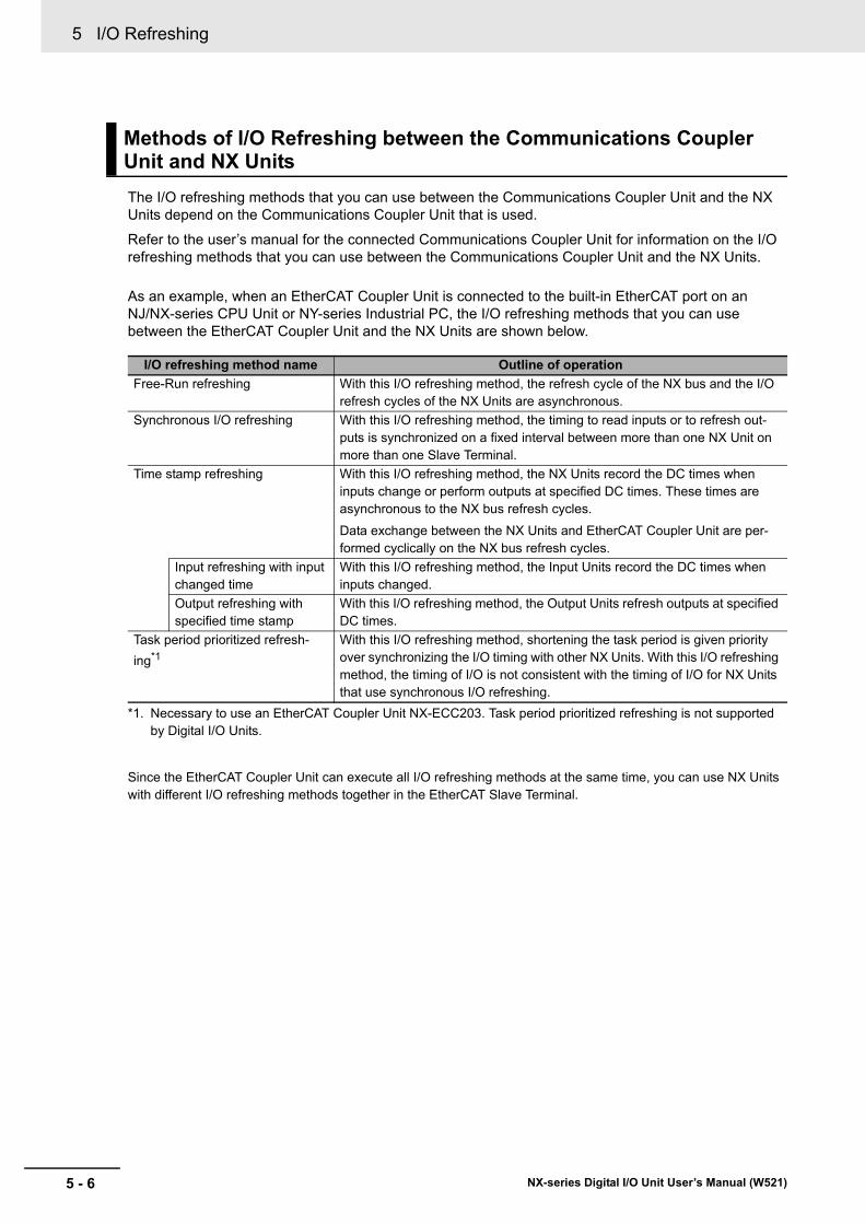
5 I/O Refreshing
5 - 6 NX-series Digital I/O Unit User’s Manual (W521)
The I/O refreshing methods that you can use between the Communications Coupler Unit and the NX Units depend on the Communications Coupler Unit that is used.
Refer to the user’s manual for the connected Communications Coupler Unit for information on the I/O refreshing methods that you can use between the Communications Coupler Unit and the NX Units.
As an example, when an EtherCAT Coupler Unit is connected to the built-in EtherCAT port on an NJ/NX-series CPU Unit or NY-series Industrial PC, the I/O refreshing methods that you can use between the EtherCAT Coupler Unit and the NX Units are shown below.
*1. Necessary to use an EtherCAT Coupler Unit NX-ECC203. Task period prioritized refreshing is not supported by Digital I/O Units.
Since the EtherCAT Coupler Unit can execute all I/O refreshing methods at the same time, you can use NX Units with different I/O refreshing methods together in the EtherCAT Slave Terminal.
Methods of I/O Refreshing between the Communications Coupler Unit and NX Units
I/O refreshing method name Outline of operationFree-Run refreshing With this I/O refreshing method, the refresh cycle of the NX bus and the I/O
refresh cycles of the NX Units are asynchronous.Synchronous I/O refreshing With this I/O refreshing method, the timing to read inputs or to refresh out-
puts is synchronized on a fixed interval between more than one NX Unit on more than one Slave Terminal.
Time stamp refreshing With this I/O refreshing method, the NX Units record the DC times when inputs change or perform outputs at specified DC times. These times are asynchronous to the NX bus refresh cycles.
Data exchange between the NX Units and EtherCAT Coupler Unit are per-formed cyclically on the NX bus refresh cycles.
Input refreshing with input changed time
With this I/O refreshing method, the Input Units record the DC times when inputs changed.
Output refreshing with specified time stamp
With this I/O refreshing method, the Output Units refresh outputs at specified DC times.
Task period prioritized refresh-ing*1
With this I/O refreshing method, shortening the task period is given priority over synchronizing the I/O timing with other NX Units. With this I/O refreshing method, the timing of I/O is not consistent with the timing of I/O for NX Units that use synchronous I/O refreshing.
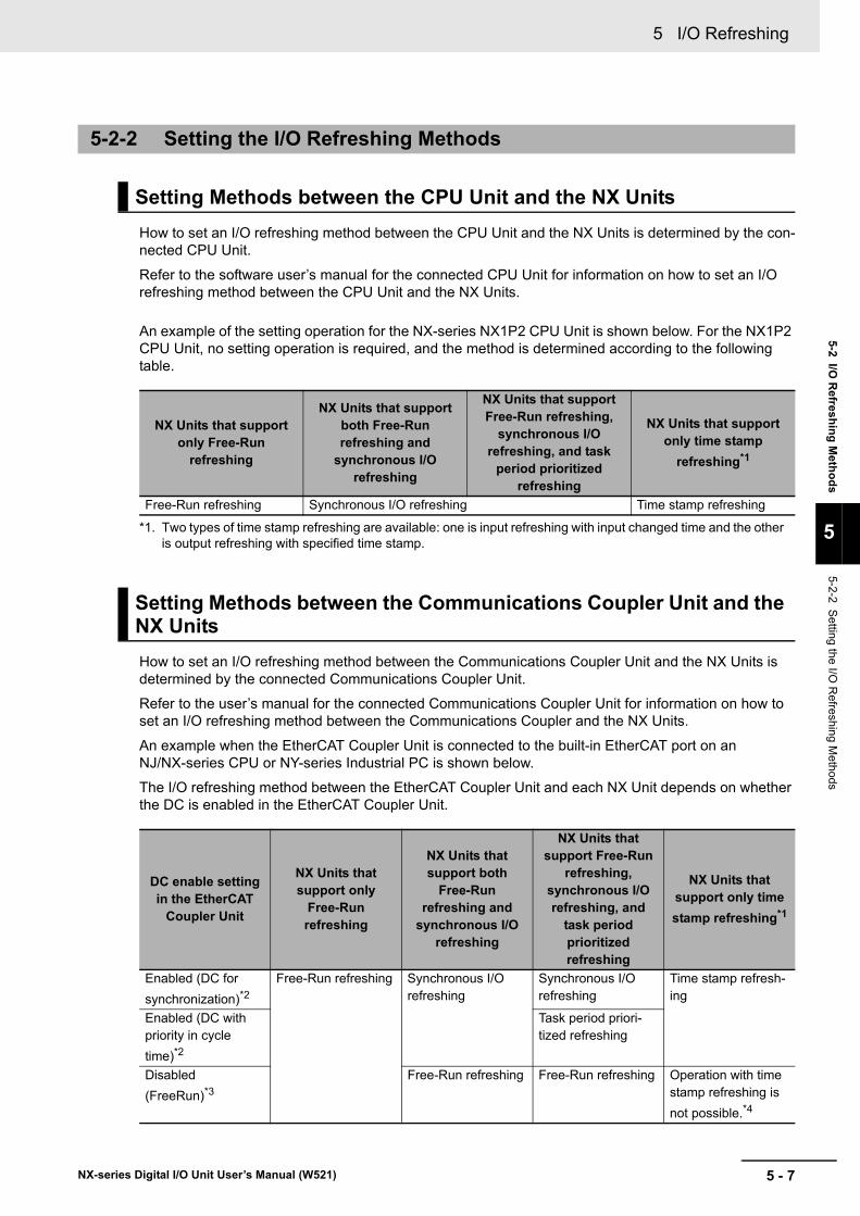
5 - 7
5 I/O Refreshing
NX-series Digital I/O Unit User’s Manual (W521)
5-2 I/O R
efreshing Methods
5
5-2-2 Setting the I/O
Refreshing M
ethods
How to set an I/O refreshing method between the CPU Unit and the NX Units is determined by the con-nected CPU Unit.
Refer to the software user’s manual for the connected CPU Unit for information on how to set an I/O refreshing method between the CPU Unit and the NX Units.
An example of the setting operation for the NX-series NX1P2 CPU Unit is shown below. For the NX1P2 CPU Unit, no setting operation is required, and the method is determined according to the following table.
How to set an I/O refreshing method between the Communications Coupler Unit and the NX Units is determined by the connected Communications Coupler Unit.
Refer to the user’s manual for the connected Communications Coupler Unit for information on how to set an I/O refreshing method between the Communications Coupler and the NX Units.
An example when the EtherCAT Coupler Unit is connected to the built-in EtherCAT port on an NJ/NX-series CPU or NY-series Industrial PC is shown below.
The I/O refreshing method between the EtherCAT Coupler Unit and each NX Unit depends on whether the DC is enabled in the EtherCAT Coupler Unit.
5-2-2 Setting the I/O Refreshing Methods
Setting Methods between the CPU Unit and the NX Units
NX Units that support only Free-Run
refreshing
NX Units that support both Free-Run refreshing and
synchronous I/O refreshing
NX Units that support Free-Run refreshing,
synchronous I/O refreshing, and task
period prioritized refreshing
NX Units that support only time stamp
refreshing*1
*1. Two types of time stamp refreshing are available: one is input refreshing with input changed time and the other is output refreshing with specified time stamp.
Free-Run refreshing Synchronous I/O refreshing Time stamp refreshing
Setting Methods between the Communications Coupler Unit and the NX Units
DC enable setting in the EtherCAT
Coupler Unit
NX Units that support only
Free-Run refreshing
NX Units that support both
Free-Run refreshing and
synchronous I/O refreshing
NX Units that support Free-Run
refreshing, synchronous I/O refreshing, and
task period prioritized refreshing
NX Units that support only time stamp refreshing*1
Enabled (DC for synchronization)*2
Free-Run refreshing Synchronous I/O refreshing
Synchronous I/O refreshing
Time stamp refresh-ing
Enabled (DC with priority in cycle time)*2
Task period priori-tized refreshing
Disabled (FreeRun)*3
Free-Run refreshing Free-Run refreshing Operation with time stamp refreshing is not possible.*4

5 I/O Refreshing
5 - 8 NX-series Digital I/O Unit User’s Manual (W521)
The I/O refreshing methods that you can use depend on the model of the NX Unit. After you decide on which I/O refreshing method to use, select the NX Units.
With this I/O refreshing method, the refresh cycle of the NX bus and I/O refresh cycles of the NX Units are asynchronous.
Digital I/O Units read inputs or refresh outputs at the time of I/O refreshing.
This method is used when it is not necessary to be aware of factors such as the I/O timing jitter and the concurrency of the timing to read inputs and refresh outputs between the NX Units.
CPU Unit OperationThe following describes the operation of Free-Run refreshing between the NX-series NX1P2 CPU Unit and the NX Units.• The CPU Unit performs I/O refreshing for NX Units. (Refer to (a) in the figure below.)• The NX Units read inputs or refresh outputs at the time of I/O refreshing. (Refer to (b) in the figure
below.)• The CPU Unit can read the most recent input value at the time of I/O refreshing and the NX Units
can control the most recent output value at the time of I/O refreshing. However, timing to read inputs or to refresh outputs for each NX Unit does not occur at the same time. (Refer to (c) in the figure below.)
• The interval of I/O refreshing varies with the processing conditions of the CPU Unit. Therefore, the interval of the timing to read inputs or to refresh outputs for NX Unit is not always the same. (Refer to (d) in the figure below.)
• In order to read input values correctly, you must set the inputs before the total of the ON/OFF response time and the input filter time from the timing to read inputs for each NX Unit.
• The ON/OFF response time is needed from the timing to refresh outputs until setting the output status of external terminals on the NX Units.
*1. Two types of time stamp refreshing are available: one is input refreshing with input changed time and the other is output refreshing with specified time stamp.
*2. The EtherCAT Slave Terminal operates in DC Mode.*3. The EtherCAT Slave Terminal operates in Free-Run Mode.*4. Refer to P. 5-26 and P. 5-32 for information on the operation when the DC is set to Disabled (FreeRun).
5-2-3 Selecting NX Units
5-2-4 Free-Run Refreshing
Description of Operation

5 - 9
5 I/O Refreshing
NX-series Digital I/O Unit User’s Manual (W521)
5-2 I/O R
efreshing Methods
5
5-2-4 Free-Run R
efreshing
I/O refreshingof the NX bus
Digital Input Unit A
Digital Input Unit B
(d) Interval of the timing to read inputs is not constant.
Timing to read inputs for each Unit is not simultaneous.
ON/OFF response time
Input filter timeON/OFF response time
Input filter time
Timing toread inputs
(c)
(b)
(a) I/O refreshing for NX Units
Set inputsRead inputs to the Unit
Input refreshing Output refreshing
Inputs
Digital Output Unit A
Digital Output Unit B
(d) Interval of the timing to refresh outputs is not constant.
Timing to refresh outputs for each Unit is not simultaneous.
ON/OFF response time
ON/OFF response time
Timing torefreshoutputs
I/O refreshingof the NX bus
(a) I/O refreshing for NX Units
(b)
(c)
Refresh outputsSet outputs
Input refreshing Output refreshing
Outputs

5 I/O Refreshing
5 - 10 NX-series Digital I/O Unit User’s Manual (W521)
Slave Terminal OperationThe following describes the operation of Free-Run refreshing for Slave Terminals.• The Communications Coupler Unit performs I/O refreshing for NX Units. (Refer to (a) in the figure
below.)• The NX Units read inputs or refresh outputs at the time of I/O refreshing. (Refer to (b) in the figure
below.)• The Communications Coupler Unit can read the most recent input value at the time of I/O refresh-
ing and the NX Units can control the most recent output value at the time of I/O refreshing. How-ever, the timing to read inputs or to refresh outputs for each NX Unit in the Slave Terminal does not occur at the same time. (Refer to (c) in the figure below.)
• The interval of I/O refreshing varies with the processing conditions of the Communications Cou-pler Unit or the host communications master. Therefore, the interval of the timing to read inputs or to refresh outputs for NX Unit is not always the same. (Refer to (d) in the figure below.)
• In order to read input values correctly, you must set the inputs before the total of the ON/OFF response time and the input filter time from the timing to read inputs for each NX Unit.
• The ON/OFF response time is required from when outputs are updated until the output status is set on the external terminals of the NX Units.

5 - 11
5 I/O Refreshing
NX-series Digital I/O Unit User’s Manual (W521)
5-2 I/O R
efreshing Methods
5
5-2-4 Free-Run R
efreshing
I/O refreshingof the NX bus
Digital Input Unit A
Digital Input Unit B
(d) Interval of the timing to read inputs is not constant.
Timing to read inputs for each Unit is not simultaneous.
ON/OFF response time
Input filter timeON/OFF response time
Input filter time
Timing toread inputs
(c)
(b)
(a) I/O refreshing for NX Units
Set inputsRead inputs to the Unit
Input refreshing Output refreshing
Inputs
Digital Output Unit A
Digital Output Unit B
(d) Interval of the timing to refresh outputs is not constant.
Timing to refresh outputs for each Unit is not simultaneous.
ON/OFF response time
ON/OFF response time
Timing torefreshoutputs
I/O refreshingof the NX bus
(a) I/O refreshing for NX Units
(b)
(c)
Refresh outputsSet outputs
Input refreshing Output refreshing
Outputs

5 I/O Refreshing
5 - 12 NX-series Digital I/O Unit User’s Manual (W521)
Add NX Units that support Free-Run refreshing to the CPU Unit configuration or Slave Terminal configuration.
After you add the NX Units, set an I/O refreshing method depending on the connected CPU Unit or Communications Coupler Unit so that these NX Units operate with Free-Run refreshing.
Refer to 5-2-2 Setting the I/O Refreshing Methods on page 5-7 for information on how to set an I/O refreshing method.
The I/O refreshing method described below. Among Slave Terminals, this refreshing method is sup-ported only by EtherCAT Slave Terminals.• The timing to read inputs is synchronized on a fixed interval between more than one NX Unit con-
nected to a CPU Unit.• The timing to read inputs is synchronized on a fixed interval between more than one NX Unit on more
than one Slave Terminal.
This method is used when the problem such as input timing jitter or offset of timing to read inputs between more than one NX Unit happens.
CPU Unit OperationThe following describes the operation of synchronous input refreshing between the NX-series NX1P2 CPU Unit and the NX Units.• All Digital Input Units and Analog Input Units that are connected to the CPU Units and operate
with synchronous input refreshing read their inputs at the same time at a fixed interval based on the synchronization timing. (Refer to (a) in the figure below.)
• The CPU Unit reads the input values, which are read by the Unit at the timing of reading inputs, at immediate I/O refreshing. (Refer to (b) in the figure below.)
• The interval of I/O refreshing varies with the processing conditions of the CPU Unit. (Refer to (c) in the figure below.) The timing to read inputs will be at a fixed interval. (Refer to (d) and (e) in the figure below.)
• The timing of reading inputs, the synchronization timing, and the maximum NX bus I/O refresh cycle are automatically calculated by the Sysmac Studio according to the input refresh cycles of the NX Units on the CPU Unit when a Unit configuration in the CPU Unit is created and set up.
• In order to read input values correctly, you must determine the inputs before the total of the ON/OFF response time and input filter time from the timing to read inputs for each NX Unit. (Refer to (f) in the figure below.)
Settings
5-2-5 Synchronous Input Refreshing
Description of Operation

5 - 13
5 I/O Refreshing
NX-series Digital I/O Unit User’s Manual (W521)
5-2 I/O R
efreshing Methods
5
5-2-5 Synchronous Input R
efreshing
Offset between synchronization timing and timing to read inputs
This time is automaticallycalculated by the SysmacStudio.
(a) All Input Units that support synchronous input refreshing read their inputs simultaneously.
I/O refreshing synchronizationThe longest AD conversion time is within one cycle.
Synchronization timing Synchronizationtiming
1 2 3 4
Input 1 Input 2
AD conversion time for all Units.
Synchronization timingConstantConstant
Constant Constant
(b) The CPU Unit reads the data that is read by the Unit at I/O refreshing.
(c) Interval of I/O refreshing is not constant.
1 2 3 4
Input 1 Input 2
Digital Input Unit A
Digital Input Unit B
Analog Input Unit A
Analog Input Unit B
Not constant.
1 2 3 4
Input 1 Input 2
I/O refreshing of the NX bus
(d) Interval of synchronization timing is constant.
AD conversion starts
ON/OFF response time Input filter time
(e) Constant
(f) Set inputs
(f)(f)
ON/OFF responsetime Input filter time
AD conversion time for all Units.
Input refreshingOutput refreshing

5 I/O Refreshing
5 - 14 NX-series Digital I/O Unit User’s Manual (W521)
Slave Terminal OperationThe following describes the operation of synchronous input refreshing of an EtherCAT Slave Termi-nal connected to the built-in EtherCAT port.• All Digital Input Units and Analog Input Units that operate with synchronous input refreshing in the
Slave Terminal read their inputs at the same time at a fixed interval bases on Sync0. (Refer to (a) in the figure below.)*1
• The Communications Coupler Unit reads the input values, which are read by the Unit at the timing of reading inputs, at immediate I/O refreshing. (Refer to (b) in the figure below.)
• The interval of I/O refreshing varies with the processing conditions of the Communications Cou-pler Unit or the host communications master. (Refer to (c) in the figure below.) The timing to read inputs will be at a fixed interval. (Refer to (d) and (e) in the figure below.)
• The Sync0, the timing to read inputs and the maximum NX bus I/O refresh cycle of the Slave Ter-minals are automatically calculated by the Sysmac Studio according to the input refresh cycle of the NX Units in the Slave Terminals when the Slave Terminals are configured and set up.
• In order to read input values correctly, you must determine the inputs before the total of the ON/OFF response time and the input filter time from the timing to read inputs for each NX Unit. (Refer to (f) in the figure below.)
*1.If multiple Slave Terminals are present on the same EtherCAT network, refer to the NX-series EtherCAT Coupler Unit User’s Manual (Cat. No. W519-E1-05 or later) for the range of available Slave Terminals that operate at the same timing.

5 - 15
5 I/O Refreshing
NX-series Digital I/O Unit User’s Manual (W521)
5-2 I/O R
efreshing Methods
5
5-2-5 Synchronous Input R
efreshing
Offset between Sync0 and timing to read inputs
This time is automaticallycalculated by the SysmacStudio.
(a) All Input Units that support synchronous input refreshing read their inputs simultaneously.
I/O refreshing synchronizationThe longest AD conversion time is within one cycle.
Sync0 Sync0
1 2 3 4
Input 1 Input 2
AD conversion time for all Units.
Sync0ConstantConstant
Constant Constant
(b) The Communications Coupler Unit reads the data that is read by the Unit at I/O refreshing.
(c) Interval of I/O refreshing is not constant.
1 2 3 4
Input 1 Input 2
Digital Input Unit A
Digital Input Unit B
Analog Input Unit A
Analog Input Unit B
Not constant.
1 2 3 4
Input 1 Input 2
I/O refreshing of the NX bus
(d) Interval of Sync0 is constant.
AD conversion starts
ON/OFF response time Input filter time
(e) Constant
(f) Set inputs
(f)(f)
ON/OFF responsetime Input filter time
AD conversion time for all Units.
Input refreshingOutput refreshing

5 I/O Refreshing
5 - 16 NX-series Digital I/O Unit User’s Manual (W521)
Add NX Units that support synchronous I/O refreshing to the CPU Unit configuration or Slave Terminal configuration.
After you add the NX Units, set an I/O refreshing method depending on the connected CPU Unit or Communications Coupler Unit so that these NX Units operate with synchronous I/O refreshing.
Refer to 5-2-2 Setting the I/O Refreshing Methods on page 5-7 for information on how to set an I/O refreshing method.
The I/O refreshing method described below. Among Slave Terminals, this refreshing method is supported only by EtherCAT Slave Terminals.• The timing to refresh outputs is synchronized on a fixed interval between more than one NX Unit con-
nected to a CPU Unit.• The timing to reresh outputs is synchronized on a fixed interval between more than one NX Unit on
more than one Slave Terminal.
This method is used when the problem such as input timing jitter or offset of timing to refresh outputs between more than one NX Unit happens.
CPU Unit OperationThe following describes the operation of synchronous output refreshing between the NX-series NX1P2 CPU Unit and the NX Units.• All Digital Output Units and Analog Output Units that are connected to the CPU Units and operate
with synchronous output refreshing refresh their outputs at the same time at a fixed interval based on the synchronization timing. (Refer to (a) in the figure below.)
• The CPU Unit refreshes the output values at I/O refreshing. (Refer to (b) in the figure below.)• The interval of I/O refreshing varies with the processing conditions of the CPU Unit. (Refer to (c) in
the figure below.) The timing to refresh outputs will be at a fixed interval. (Refer to (d) and (e) in the figure below.)
• The timing of refreshing outputs, the synchronization timing, and the maximum NX bus I/O refresh cycle are automatically calculated by the Sysmac Studio according to the output refresh cycles of the NX Units on the CPU Unit when a Unit Configuration in the CPU Unit is created and set up.
• The ON/OFF response time is needed from the timing to refresh outputs until setting the output status of external terminals on the NX Units. (Refer to (f) in the figure below.)
Settings
5-2-6 Synchronous Output Refreshing
Description of Operation

5 - 17
5 I/O Refreshing
NX-series Digital I/O Unit User’s Manual (W521)
5-2 I/O R
efreshing Methods
5
5-2-6 Synchronous O
utput Refreshing
Slave Terminal OperationThe following describes the operation of synchronous output refreshing of an EtherCAT Slave Ter-minal connected to the built-in EtherCAT port.• All Digital Output Units and Analog Output Units that operate with synchronous output refreshing
in the Slave Terminal refresh their outputs at the same time at a fixed interval based on Sync0. (Refer to (a) in the figure below.)*1
• The Communication Coupler Unit refreshes the output values at I/O refreshing. Refer to (b) in the figure below.)
• The interval of I/O refreshing varies with the processing conditions of the Communications Cou-pler Unit or the host communications master. (Refer to (c) in the figure below.) The timing to refresh outputs will be at a fixed interval. (Refer to (d) and (e) in the figure below.)
• The Sync0, the timing to refresh outputs and the maximum NX bus I/O refresh cycle of the Slave Terminals are automatically calculated by the Sysmac Studio according to the output refresh cycle of the NX Units in the Slave Terminals when the Slave Terminals are configured and set up.
• The ON/OFF response time is needed from the timing to refresh outputs until setting the output status of external terminals on the NX Units. (Refer to (f) in the figure below.)
*1. If multiple Slave Terminals are present on the same EtherCAT network, refer to the NX-series EtherCAT Coupler Unit User’s Manual (Cat. No. W519-E1-05 or later) for the range of available Slave Terminals that operate at the same timing.
Offset between synchronization timing and timing to refresh outputsThis time is automatically calculated by the Sysmac Studio.
(c) Interval of I/O refreshing is not constant.
I/O refreshing synchronizationThe longest DA conversion timeis within one cycle. (d) Interval of synchronization timing
is constant.
(b) The CPU Unit refreshes the output values at I/O refreshing.
Timing to refresh outputs
Synchronizationtiming
Synchronizationtiming
1 2 3 4
Synchronization timingConstantConstant
1 2 3 4
Output 1 Output 2
ON/OFF response time
DA conversiontime
1 2 3 41 2 3 4
Output 2
1 2 3 41 2 3 4
Output 1 Output 2
Digital Output Unit A
Digital Output Unit B
Analog Output Unit A
Analog Output Unit B
Not constant.
(e) ConstantConstantConstant
Output 1
Wait time
Wait time
I/O refreshing of the NX bus
(a) All Outputs Units that support synchronous output refreshing read their outputs simultaneously.
(f) Set outputs
Input refreshingOutput refreshing

5 I/O Refreshing
5 - 18 NX-series Digital I/O Unit User’s Manual (W521)
Same as the settings for synchronous input refreshing. Refer to Settings in 5-2-5 Synchronous Input Refreshing on page 5-12 for details.
Settings
Offset between Sync0 and timing to refresh outputsThis time is automatically calculated by the Sysmac Studio.
(c) Interval of I/O refreshing is not constant.
I/O refreshing synchronizationThe longest DA conversion timeis within one cycle. (d) Interval of Sync0 is constant.
(b) The Communication Coupler Unit refreshes the output values at I/O refreshing.
Timing to refresh outputs
Sync0 Sync0
1 2 3 4
Sync0ConstantConstant
1 2 3 4
Output 1 Output 2
DA conversiontime
1 2 3 41 2 3 4
Output 2
1 2 3 41 2 3 4
Output 1 Output 2
Digital Output Unit A
Digital Output Unit B
Analog Output Unit A
Analog Output Unit B
Not constant.
(e) ConstantConstantConstant
Output 1
Wait time
Wait time
ON/OFF response time
I/O refreshing of the NX bus
(a) All Outputs Units that support synchronous output refreshing read their outputs simultaneously.
(f) Set outputs
Input refreshingOutput refreshing

5 - 19
5 I/O Refreshing
NX-series Digital I/O Unit User’s Manual (W521)
5-2 I/O R
efreshing Methods
5
5-2-7 Time Stam
p Refreshing
With this I/O refreshing method, the NX Units record the DC times when inputs change or perform out-puts at specified DC times. These times are not synchronized to the NX bus refresh cycles. Among Slave Terminals, only EtherCAT Slave Terminals support this refreshing method.
Data exchange between the NX Units and CPU Unit or EtherCAT Coupler Unit are performed cyclically on the NX bus refresh cycles.
There are the following two I/O refreshing methods.
• Input refreshing with input changed time• Output refreshing with specified time stamp
Each of these I/O refreshing methods is described below.
5-2-7 Time Stamp Refreshing

5 I/O Refreshing
5 - 20 NX-series Digital I/O Unit User’s Manual (W521)
With this I/O refreshing method, the Input Units record the DC times when the inputs changed. The DC times are not synchronized to the NX bus refresh cycles. Among Slave Terminals, only EtherCAT Slave Terminals support this refreshing method.
The CPU Unit or EtherCAT Coupler Unit cyclically reads both the input values and the DC times when the inputs changed on the NX bus refresh cycles.
In the descriptions below, the DC time when the input changed is called the input changed time.
You can use the Input Units that support input refreshing with input changed time with the Output Units that support output refreshing with specified time stamp to control an output at a fixed interval after a sensor input changes.
CPU Unit operationThe following describes the operation of input refreshing with input changed time between the NX-series NX1P2 CPU Unit and the NX Units.• The NX Units that support input refreshing with input changed time record the DC times when an
input changes for each input bit. The DC times that the Units record are the DC times for which the status changes of the input terminals passed the ON/OFF response time and reached the internal circuits.
• The CPU Unit reads the input values and the input changed times from the NX Units at I/O refreshing. The input values that the CPU Unit reads are not the input values at the point when the input change times were recorded, but the input values at I/O refreshing.
• All Digital Input Units that operate with input refreshing with input changed times and are con-nected to the CPU Unit read the input changed times at the same time at a fixed interval based on synchronization timing. (Refer to (a) in the figure below.)
• The timing of reading input changed times is the same as the timing at which all Digital Input Units and Analog Input Units that operate with synchronous input refreshing and are connected to the CPU Unit read their inputs.
• The timing of reading input values is at I/O refreshing, which is different from the timing of reading input changed times.
• The CPU Unit reads the input changed times and input values at immediate I/O refreshing after the input changed times are read. (Refer to (b) in the figure below.)
• The interval of I/O refreshing varies with the processing conditions of the CPU Unit. (Refer to (c) in the figure below.) The timing to read input changed times will be at a fixed interval. (Refer to (d) and (e) in the figure below.)
• The timing of reading input changed times, the synchronization timing, and the maximum NX bus I/O refresh cycle are automatically calculated by the Sysmac Studio according to the input refresh cycles of the NX Units on the CPU Unit when a Unit Configuration in the CPU Unit is created and set up.
5-2-8 Input Refreshing with Input Changed Time
Description of Operation

5 - 21
5 I/O Refreshing
NX-series Digital I/O Unit User’s Manual (W521)
5-2 I/O R
efreshing Methods
5
5-2-8 Input Refreshing w
ith Input Changed Tim
e
Synchronization timing Synchronization timingSynchronizationtiming
T1 T2
T1 T2T0
T1 T2T0
Digital Input Unit
Analog Input Unit
I/O refreshing of the NX bus
CPU Unit
Offset between synchronization timing and timing to read inputsThis time is automaticallycalculated by the SysmacStudio.
I/O refreshing synchronizationThe longest AD conversion time is within one cycle.
Output refreshingInput refreshing
Constant Constant
(b) The CPU Unit reads the input changed times that are read by the Unit and the input values at this point at I/O refreshing.
(c) Interval of I/O refreshing is not constant.
Not constant.
DC time
Input value
Inputchanged
time
Digital Input Unitthat supports input refreshing with input changed time
Inputterminals
Inputvalue
Inputchanged
time
Input 1 Input 2 Input 1 Input 2 Input 1 Input 2
Constant Constant (e) Constant
Input filter time
ON/OFF response time
AD conversion time for all Units.
ON/OFF response time
Records T1, which is the DC time at the point when the input value changed.
(a) All Units that support input refreshing with input changed time read their input changed times simultaneously.All Input Units that support synchronous input refreshing read their inputs simultaneously.
(d) Interval of synchronization timing is constant.

5 I/O Refreshing
5 - 22 NX-series Digital I/O Unit User’s Manual (W521)
• You can select to either detect changes at the input rising edge, or at the input falling edge. Make the setting in advance.
• NX Units that support input refreshing with input changed time do not have an input filter function.• You can select at which point the input changed times are recorded when the inputs change more
than one time during the NX bus I/O refresh cycle. Make the setting in advance.
• The input changed times are retained if the inputs do not change.
Synchronization timing Synchronization timing Synchronization timing
T1 T2DC time
T1 T2T0
Input value
Inputchangedtime
The trigger setting isRising Edge.
I/O refreshing of the NX bus
Records the DC time at the point when the input value changes from OFF to ON.
Records the DC time at the point when the input value changes from ON to OFF.
The trigger setting isFalling Edge.
Digital Input Unitthat supports input refreshing with input changed time
Input refreshingOutput refreshing
Synchronization timing Synchronization timing Synchronization timing
T1 T2
T1 T2T0
DC time
Input value
The mode setting isContinuous.
I/O refreshing of the NX bus
Records the DC time at the point of the last trigger during the cycle.
The mode setting isOne-shot.
Records the DC time at the point of the first trigger during the cycle.
Inputchangedtime
Digital Input Unitthat supports input refreshing with input changed time
Input refreshingOutput refreshing
5 - 23
5 I/O Refreshing
NX-series Digital I/O Unit User’s Manual (W521)
5-2 I/O R
efreshing Methods
5
5-2-8 Input Refreshing w
ith Input Changed Tim
e
Slave Terminal OperationThe following describes the operation of input refreshing with input changed time of an EtherCAT Slave Terminal connected to the built-in EtherCAT port.• The NX Units that support input refreshing with input changed time record the DC times when an
input changes for each input bit. The DC times that the Units record are the DC times for which the status changes of the input terminals passed the ON/OFF response time and reached the internal circuits.
• The EtherCAT Coupler Unit reads the input values and the input changed times from the NX Units at I/O refreshing. The input values that the EtherCAT Coupler Unit read are not the values at the point when the input change times were recorded, but the values at I/O refreshing.
• All Digital Input Units that operate with input refreshing with input changed times in the Slave Ter-minal read the input changed times at the same time at a fixed interval based on Sync0. (Refer to (a) in the figure below.)*1
• The timing of reading input changed times is the same as the timing at which all Digital Input Units and Analog Input Units that operate with synchronous input refreshing in the Slave Terminal read their inputs.
• The timing of reading input values is at I/O refreshing, which is different from the timing of reading input changed times.
• The EtherCAT Coupler Unit reads the input changed times and input values at immediate I/O refreshing after the input changed times are read. (Refer to (b) in the figure below.)
• The interval of I/O refreshing varies with the processing conditions of the EtherCAT Coupler Unit or the EtherCAT master. (Refer to (c) in the figure below.) The timing of reading input changed times will be at a fixed interval. (Refer to (d) and (e) in the figure below.)
• Sync0, the timing of reading input changed times, and the maximum NX bus I/O refresh cycle for multiple Slave Terminals are automatically calculated by the Sysmac Studio according to the input refresh cycles of the NX Units in the Slave Terminals when the Slave Terminals are configured and set up.
*1. If multiple Slave Terminals are present on the same EtherCAT network, refer to the NX-series EtherCAT Coupler Unit User’s Manual (Cat. No. W519-E1-05 or later) for the range of available Slave Terminals that operate at the same timing.

5 I/O Refreshing
5 - 24 NX-series Digital I/O Unit User’s Manual (W521)
Sync0 Sync0 Sync0
T1 T2
T1 T2T0
T1 T2T0
Digital Input Unit
Analog Input Unit
I/O refreshing of the NX bus
CommunicationsCoupler Unit
Offset between Sync0 and timing to read inputsThis time is automaticallycalculated by the SysmacStudio.
I/O refreshing synchronizationThe longest AD conversion time is within one cycle.
Output refreshingInput refreshing
Constant Constant
(b) The Communications Coupler Unit reads the input changed times that are read by the Unit and the input values at this point at I/O refreshing.
(c) Interval of I/O refreshing is not constant.
Not constant.
DC time
Input value
Inputchanged
time
Digital Input Unitthat supports input refreshing with input changed time
Inputterminals
Inputvalue
Inputchanged
time
Input 1 Input 2 Input 1 Input 2 Input 1 Input 2
Constant Constant (e) Constant
Input filter time
ON/OFF response time
AD conversion time for all Units.
ON/OFF response time
Records T1, which is the DC time at the point when the input value changed.
(a) All Units that support input refreshing with input changed time read their input changed times simultaneously.All Input Units that support synchronous input refreshing read their inputs simultaneously.
(d) Interval of Sync0 is constant.

5 - 25
5 I/O Refreshing
NX-series Digital I/O Unit User’s Manual (W521)
5-2 I/O R
efreshing Methods
5
5-2-8 Input Refreshing w
ith Input Changed Tim
e
• You can select to either detect changes at the input rising edge, or at the input falling edge. Make the setting in advance.
• NX Units that support input refreshing with input changed time do not have an input filter function.• You can select at which point the input changed times are recorded when the inputs change more
than one time during the NX bus I/O refresh cycle. Make the setting in advance.
• The input changed times are retained if the inputs do not change.
Sync0 Sync0 Sync0
T1 T2DC time
T1 T2T0
Input value
Inputchangedtime
The trigger setting isRising Edge.
I/O refreshing of the NX bus
Records the DC time at the point when the input value changes from OFF to ON.
Records the DC time at the point when the input value changes from ON to OFF.
The trigger setting isFalling Edge.
Digital Input Unitthat supports input refreshing with input changed time
Input refreshingOutput refreshing
Sync0 Sync0 Sync0
T1 T2
T1 T2T0
DC time
Input value
The mode setting isContinuous.
I/O refreshing of the NX bus
Records the DC time at the point of the last trigger during the cycle.
The mode setting isOne-shot.
Records the DC time at the point of the first trigger during the cycle.
Inputchangedtime
Digital Input Unitthat supports input refreshing with input changed time
Input refreshingOutput refreshing

5 I/O Refreshing
5 - 26 NX-series Digital I/O Unit User’s Manual (W521)
Add NX Units that support input refreshing with input changed time to the CPU Unit configuration or Slave Terminal configuration.
After you add the NX Units, set an I/O refreshing method depending on the connected CPU Unit or Communications Coupler Unit so that these NX Units operate with input refreshing with input changed time.
Refer to 5-2-2 Setting the I/O Refreshing Methods on page 5-7 for information on how to set an I/O refreshing method.
Also, using the NX Unit operation settings, set the edge to read the input changed time or operation mode.
Refer to NX Units in Input Refreshing with Input Changed Time on page 6-12 in 6-3 List of Settings on page 6-7 for details on the settings.
Additional Information
Do not set the DC enable setting to Disabled (FreeRun). If it is set to Disabled, the input refreshing with input changed time will not operate correctly. However, an error does not occur even if it is disabled. If the DC enable setting is set to Disabled (FreeRun), the input values reflect the actual input status, but the input changed times retain the default values and do not change.
Settings

5 - 27
5 I/O Refreshing
NX-series Digital I/O Unit User’s Manual (W521)
5-2 I/O R
efreshing Methods
5
5-2-9 Output R
efreshing with Specified Tim
e Stamp
With this I/O refreshing method, the Output Units refresh outputs at the DC times specified by the user program. The specified DC times are not synchronized to the NX bus refresh cycles. Among Slave Terminals, only EtherCAT Slave Terminals support this refreshing method.
The CPU Unit or EtherCAT Coupler Unit cyclically sets the output set values and the DC times to refresh outputs to the Output Units on the NX bus refresh cycles.
In the descriptions below, the DC time to refresh the output is called the specified time.
You can use the Input Units that support input refreshing with input changed time with the Output Units that support output refreshing with specified time stamp to control outputs at fixed intervals after the sensor inputs change.
5-2-9 Output Refreshing with Specified Time Stamp
5 I/O Refreshing
5 - 28 NX-series Digital I/O Unit User’s Manual (W521)
CPU Unit OperationThe following describes the operation of output refreshing with specified time stamp between the NX-series NX1P2 CPU Unit and the NX Units.• You can specify the specified time and the output set value for each output bit. You can also set
the same specified time for multiple output bits.• The NX Bus Function Module of the CPU Unit sets the output set values and the specified times
to the NX Units and acquires the output status at I/O refreshing. (Refer to (a) in the figure below.)• The output status is used when you determine that the output was refreshed normally at the spec-
ified time. Refer to 5-2-10 An Example of Turning ON Outputs at Specific Times After the Sensor Inputs Change on page 5-33 for an example of determining that the output was refreshed.
• The NX Units turn ON the output status when the specified times are set.• The NX Units refresh outputs and turn OFF the output status at the specified times. The values of
outputs that the NX Units refresh are the output set values at the specified times. (Refer to (b) in the figure below.)
• The ON/OFF response time is needed from the specified time until setting the output status of external terminals on the NX Units.
• If the next specified time is set before the current specified time is reached, the NX Units overwrite the current specified time to the next specified time. The current specified time is ignored.
• If the value of the specified time is 0, the output is refreshed immediately. At this time, the Output Units refresh outputs according to the output set values.
• When the specified time is set to the NX Units, if the specified time is a previous DC time, a Previ-ous Time Specified event (event code: 7001000 hex) occurs.
• To make the specified time as a future DC time when it is set to the NX Units, set the specified time to satisfy both the following conditions.
a) A future DC time at least twice the task period from the previous value of the Time Stamp of Syn-chronous Output (Refer to (c) in the figure below.)
b) A future DC time at least three times the task period from the input changed time read from the Input Units that support input refreshing with input changed time (Refer to (d) in the figure below.)
• The Time Stamp of Synchronous Output is one of I/O data in the NX Bus Function Module of the CPU Unit, and contains the DC time of synchronous outputs from the NX Unit. The I/O port name for this I/O data is " Time Stamp of Synchronous Output"*1. This I/O data is allocated per NX Unit to a CPU Unit.
*1. "" is a device name.
Description of Operation
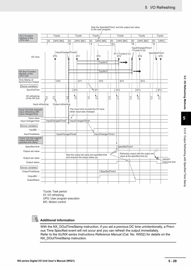
5 - 29
5 I/O Refreshing
NX-series Digital I/O Unit User’s Manual (W521)
5-2 I/O R
efreshing Methods
5
5-2-9 Output R
efreshing with Specified Tim
e Stamp
Additional Information
With the NX_DOutTimeStamp instruction, if you set a previous DC time unintentionally, a Previ-ous Time Specified event will not occur and you can refresh the output immediately.Refer to the NJ/NX-series Instructions Reference Manual (Cat. No. W502) for details on the NX_DOutTimeStamp instruction.
Sets the SpecifiedTime1 and the output set value in the user program.
ST2 ST4 ST5
SyncOutTime
InputTimeStamp
OutputTimeStamp
ST0 ST1 DC time
Refreshes output with the output setvalue at the specified time.(b)
PLC Function Module of the CPU Unit
NX Bus Function Module of the CPU Unit
Time Stamp ofSynchronous Output
Input changed time
Specified time
Input value
Output set value
Output set value
I/O refreshingof the NX bus
Device variables
Device variables
Device variables
The Input Unit records the DC timewhen input was changed.
Input Unit that supportsinput refreshing withinput changed time
Output Unit that supportsoutput refreshing withspecified time stamp
Output status
OutputStatus
Tcycle×2
Tcycle×3
Tcycle
UPG MCIO IO IO IO IOUPG MC UPG MC UPG UPG IO UPG MC MC
Tcycle Tcycle Tcycle Tcycle Tcycle
ST2
ST2
ST1 ST3
ST3
ST4
ST4ST1ST0
ST0
Sets the output set value and specified timeand acquires the output status.(a)
ON/OFFresponse time
InputBit
OutputBit
SpecifiedTime1
InputChangedTime0 InputChangedTime1
InputChangedTime0 InputChangedTime1
ST1+Tcycle×2 (c) ST3
InputChangedTime1+Tcycle×3 (d)
Tcycle: Task periodIO: I/O refreshingUPG: User program executionMC: Motion control
SpecifiedTime1InputChangedTime0
SpecifiedTime1
Output refreshingInput refreshing

5 I/O Refreshing
5 - 30 NX-series Digital I/O Unit User’s Manual (W521)
Slave Terminal OperationThe following describes the operation of output refreshing with specified time stamp of an EtherCAT Slave Terminal connected to the built-in EtherCAT port.• You can specify the specified time and the output set value for each output bit. You can also set
the same specified time for multiple output bits.• The EtherCAT Coupler Unit sets the output set values and the specified times to the NX Units and
acquires the output status at I/O refreshing. (Refer to (a) in the figure below.)• The output status is used when you determine that the output was refreshed normally at the spec-
ified time. Refer to 5-2-10 An Example of Turning ON Outputs at Specific Times After the Sensor Inputs Change on page 5-33 for an example of determining that the output was refreshed.
• The NX Units turn ON the output status when the specified times are set.• The NX Units refresh outputs and turn OFF the output status at the specified times. The values of
outputs that the NX Units refresh are the output set values at the specified times. (Refer to (b) in the figure below.)
• The ON/OFF response time is needed from the specified time until setting the output status of external terminals on the NX Units.
• If the next specified time is set before the current specified time is reached, the NX Units overwrite the current specified time to the next specified time. The current specified time is ignored.
• If the value of the specified time is 0, the output is refreshed immediately. At this time, the Output Units refresh outputs according to the output set values.
• When the specified time is set to the NX Units, if the specified time is a previous DC time, a Previ-ous Time Specified event (event code: 70010000 hex) occurs.
• To make the specified time as a future DC time when it is set to the NX Units, set the specified time to satisfy both the following conditions.
a) A future DC time at least twice the task period from the previous value of the Time Stamp of Syn-chronous Output (Refer to (c) in the figure below.)
b) A future DC time at least three times the task period from the input changed time read from the Input Units that support input refreshing with input changed time (Refer to (d) in the figure below.)
• The Time Stamp of Synchronous Output is one of I/O data in the EtherCAT Coupler Unit, and con-tains the DC time of synchronous outputs from the NX Unit. By default, it is not assigned to the I/O entry mapping, so edit the settings and assign it to the I/O entry mapping. The added I/O data is 0x200A: 02 (Time Stamp of Synchronous Output).

5 - 31
5 I/O Refreshing
NX-series Digital I/O Unit User’s Manual (W521)
5-2 I/O R
efreshing Methods
5
5-2-9 Output R
efreshing with Specified Tim
e Stamp
Additional Information
With the NX_DOutTimeStamp instruction, if you set a previous DC time unintentionally, a Previ-ous Time Specified event will not occur and you can refresh the output immediately.Refer to the instructions reference manual for the connected CPU Unit or Industrial PC for details on the NX_DOutTimeStamp instruction.
Sets the SpecifiedTime1 and the output set value in the user program.
ST2 ST4 ST5
SyncOutTime
InputTimeStamp
OutputTimeStamp
ST0 ST1 DC time
Refreshes output with the output setvalue at the specified time.(b)
CPU Unit
EtherCATCoupler Unit
Time Stamp ofSynchronous Output
Input changed time
Specified time
Input value
Output set value
Output set value
I/O refreshingof the NX bus
Device variables
Device variables
Device variables
The Input Unit records the DC timewhen input was changed.
Input Unit that supportsinput refreshing withinput changed time
Output Unit that supportsoutput refreshing withspecified time stamp
Output status
OutputStatus
Tcycle×2
Tcycle×3
Tcycle
UPG MCIO IO IO IO IOUPG MC UPG MC UPG UPG IO UPG MC MC
Tcycle Tcycle Tcycle Tcycle Tcycle
ST2
ST2
ST1 ST3
ST3
ST4
ST4ST1ST0
ST0
Sets the output set value and specified timeand acquires the output status.(a)
ON/OFFresponse time
InputBit
OutputBit
SpecifiedTime1
InputChangedTime0 InputChangedTime1
InputChangedTime0 InputChangedTime1
ST1+Tcycle×2 (c) ST3
InputChangedTime1+Tcycle×3 (d)
Tcycle: Task periodIO: I/O refreshingUPG: User program executionMC: Motion control
SpecifiedTime1InputChangedTime0
SpecifiedTime1
Output refreshingInput refreshing

5 I/O Refreshing
5 - 32 NX-series Digital I/O Unit User’s Manual (W521)
Add NX Units that support output refreshing with specified time stamp to the CPU Unit configuration or Slave Terminal configuration.
After you add the NX Units, set an I/O refreshing method depending on the connected CPU Unit or Communications Coupler Unit so that these NX Units operate with output refreshing with specified time stamp.
Refer to 5-2-2 Setting the I/O Refreshing Methods on page 5-7 for information on how to set an I/O refreshing method.
Additional Information
Do not set the DC enable setting to Disabled (FreeRun). If it is set to Disabled, the output refreshing with specified time stamp will not operate correctly. However, an error does not occur even if it is disabled. If the DC enable setting is set to Disabled (FreeRun), outputs are not refreshed regardless of the output set values and values of the specified time.
Settings

5 - 33
5 I/O Refreshing
NX-series Digital I/O Unit User’s Manual (W521)
5-2 I/O R
efreshing Methods
5
5-2-10 An E
xample of Turning O
N O
utputs at Specific Times A
fter the Sensor Inputs C
hange
The following shows an example that uses an Input Unit NX-ID3344 that supports input refreshing with input changed time and an Output Unit NX-OD2154 that supports output refreshing with specified time stamp to turn ON the output to the external output device at a specific time after the input changed time from the sensor. It is an example when using an EtherCAT Slave Terminal.
For cases in which NX-ID3344 and NX-OD2154 are used for NX-series NX1P2 CPU Units, this section explains only the points different from the case of using an EtherCAT Slave Terminal. Refer to When Used by Connecting to the CPU Unit on page 5-40 for details.
• In this example, 500 ms after the sensor input that is connected to input bit 00 of an Input Unit NX-ID3344 changes to ON, output bit 00 of an Output Unit NX-OD2154 changes to ON.
• The following determinations are performed to normally operate the programming.a) When the specified time is set to an Output Unit NX-OD2154, the validity of the specified time is
determined to make sure that the specified time is not a previous DC time.b) With an Output Unit NX-OD2154, the output was normally refreshed at the specified time is
determined.
5-2-10 An Example of Turning ON Outputs at Specific Times After the Sensor Inputs Change
Specifications of Sample Programming
EtherCATCoupler Unit
Output UnitNX-OD2154
Input UnitNX-ID3344
Built-in EtherCAT port
NJ/NX-series CPU Unit
External output device(Output)
Workpiece
Sensor(Input)
NX-ID3344Input Bit 00
NX-OD2154Output Bit 00
500 ms

5 I/O Refreshing
5 - 34 NX-series Digital I/O Unit User’s Manual (W521)
The network configuration is as follows.
A Slave Terminal with the following configuration is connected at EtherCAT node address 1. The device names that are given in the following table are used.
The task period of the primary periodic task is 1 ms.
The Unit operation settings of the Input Unit NX-ID3344 are as follows.
Network Configuration
Unit number Model Unit Device name0 NX-ECC201 EtherCAT Coupler Unit E0011 NX-ID3344 Digital Input Unit that supports input refreshing
with input changed timeN1
2 NX-OD2154 Digital Output Unit that supports output refreshing with specified time stamp
N2
Task Settings
Unit Operation Settings
Item Set value Meaning
Time Stamp (Trigger Setting) : Input Bit 00 Trigger Setting
FALSE Trigger to read the input changed time: Rising Edge
Time Stamp (mode Setting) : Input Bit 00 Mode Setting
FALSE Operation mode to read the input changed time: Continuous (Last changed time)
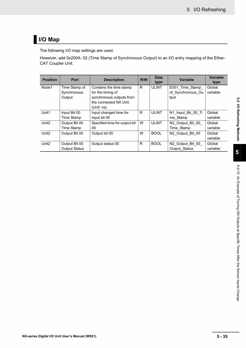
5 - 35
5 I/O Refreshing
NX-series Digital I/O Unit User’s Manual (W521)
5-2 I/O R
efreshing Methods
5
5-2-10 An E
xample of Turning O
N O
utputs at Specific Times A
fter the Sensor Inputs C
hange
The following I/O map settings are used.
However, add 0x200A: 02 (Time Stamp of Synchronous Output) to an I/O entry mapping of the Ether-CAT Coupler Unit.
I/O Map
Position Port Description R/W Data type Variable Variable
typeNode1 Time Stamp of
Synchronous Output
Contains the time stamp for the timing of synchronous outputs from the connected NX Unit. (Unit: ns)
R ULINT E001_Time_Stamp_of_Synchronous_Output
Global variable
Unit1 Input Bit 00 Time Stamp
Input changed time for input bit 00
R ULINT N1_Input_Bit_00_Time_Stamp
Global variable
Unit2 Output Bit 00 Time Stamp
Specified time for output bit 00
W ULINT N2_Output_Bit_00_Time_Stamp
Global variable
Unit2 Output Bit 00 Output bit 00 W BOOL N2_Output_Bit_00 Global variable
Unit2 Output Bit 00 Output Status
Output status 00 R BOOL N2_Output_Bit_00_Output_Status
Global variable

5 I/O Refreshing
5 - 36 NX-series Digital I/O Unit User’s Manual (W521)
LD
Internal Variables Name Data type Default value Comment
State UINT 0 Internal status of programError BOOL FALSE Error flagErrorCode WORD 16#0000 Error codeInputTimeStamp ULINT 0 Recorded input changed
timeSetOutputTimeStamp ULINT 0 DC time set for the
specified timeOffsetTimeStamp ULINT ULINT#500000000 Time from the input
changed time until the specified time (ms)
OffsetErrorTaskExeCnt ULINT ULINT#3 Error criteria for specified time
TaskPeriod ULINT ULINT#1000000 Task period (ms)TmpWork ULINT --- Workpiece for determining
specified time error
External Variables Name Data
type Comment
E001_Time_Stamp_of_Synchronous_Output ULINT DC time for the timing of synchronous outputs from the NX Unit
N1_Input_Bit_00_Time_Stamp ULINT Input changed time for input bit 00N2_Output_Bit_00 BOOL Output bit 00N2_Output_Bit_00_Time_Stamp ULINT Specified time for output bit 00N2_Output_Bit_00_Output_Status BOOL Output status for output bit 00
S
InputTimeStamp
<>ENIn1In2
StateUINT#0
=ENIn1In2
MOVEENIn
ENOOut InputTimeStamp
ENIn1In2
OffsetTimeStampTmpWork
OffsetErrorTaskExeCntTaskPeriod
*ENIn1In2
ENOOut TmpWork
UINT#0
MOVEENIn
ENOOut State WORD#16#1
MOVEENIn
ENOOut ErrorCode
<=
ENIn1In2
OffsetTimeStampTmpWork
>
InputTimeStampOffsetTimeStamp
+ENIn1In2
ENOOut SetOutputTimeStamp
MOVEENIn
ENOOut
SError
N2_Output_Bit_00
UINT#1
MOVEENIn
ENOOut State
0 State0: Wait for input bit 00 to change. If the specified time is 3 task periods or less, error end. Transit to set the specified time and to check the output.
SetOutputTimeStamp
N1_Input_Bit_00_Time_Stamp
N1_Input_Bit_00_Time_Stamp
N2_Output_Bit_00_Time_Stamp

5 - 37
5 I/O Refreshing
NX-series Digital I/O Unit User’s Manual (W521)
5-2 I/O R
efreshing Methods
5
5-2-10 An E
xample of Turning O
N O
utputs at Specific Times A
fter the Sensor Inputs C
hange
R>=
ENIn1In2
StateUINT#1
=ENIn1In2
ULINT#0
MOVEENIn
ENOOut N2_Output_Bit_00_
Time_Stamp
UINT#0
MOVEENIn
ENOOut State
ErrorCodeS
Error
N2_Output_Bit_00
1 State1: Check the output. Check the output status after the specified time has passed. Output error or output completion (Turn OFF the output.).
N2_Output_Bit_00_Output_Status
N2_Output_Bit_00_Output_Status
WORD#16#2
MOVEENIn
ENOOut
E001_Time_Stamp_Synchronous_OutputSetOutputTimeStamp

5 I/O Refreshing
5 - 38 NX-series Digital I/O Unit User’s Manual (W521)
ST
Internal Variables Name Data type Default value Comment
State UINT 0 Internal status of programError BOOL FALSE Error flagErrorCode WORD 16#0000 Error codeInputTimeStamp ULINT 0 Recorded input changed
timeSetOutputTimeStamp ULINT 0 DC time set for the
specified timeOffsetTimeStamp ULINT ULINT#500000000 Time from the input
changed time until the specified time (ms)
OffsetErrorTaskExeCnt ULINT ULINT#3 Error criteria for specified time
TaskPeriod ULINT ULINT#1000000 Task period (ms)
External Variables Name Data
type Comment
E001_Time_Stamp_of_Synchronous_Output ULINT DC time for the timing of synchronous outputs from the NX Unit
N1_Input_Bit_00_Time_Stamp ULINT Input changed time for input bit 00N2_Output_Bit_00 BOOL Output bit 00N2_Output_Bit_00_Time_Stamp ULINT Specified time for output bit 00N2_Output_Bit_00_Output_Status BOOL Output status for output bit 00

5 - 39
5 I/O Refreshing
NX-series Digital I/O Unit User’s Manual (W521)
5-2 I/O R
efreshing Methods
5
5-2-10 An E
xample of Turning O
N O
utputs at Specific Times A
fter the Sensor Inputs C
hange
CASE State OF 0: //Wait for input bit 00 to change. IF( InputTimeStamp <> N1_Input_Bit_00_Time_Stamp )THEN
InputTimeStamp:=N1_Input_Bit_00_Time_Stamp; //Save the input changed time for input bit 00.
IF( OffsetTimeStamp <= (OffsetErrorTaskExeCnt * TaskPeriod) )THEN //If the specified time is 3 task periods or less, error end. State:=0; //Transit to waiting for input bit 00 to change. Error:=TRUE; //Error registration ErrorCode:=WORD#16#0001; ELSE //Set the specified time. SetOutputTimeStamp:=InputTimeStamp+OffsetTimeStamp; N2_Output_Bit_00_Time_Stamp:=SetOutputTimeStamp; N2_Output_Bit_00:=TRUE; State:=1; //Transit to output check. END_IF; END_IF;
1: //Check the output. IF( E001_Time_Stamp_of_Synchronous_Output < SetOutputTimeStamp )THEN ; //Continue output check because the specified time has not been reached. ELSE //Check the output status because the specified time has passed. IF( N2_Output_Bit_00_Output_Status=FALSE )THEN //Output completion N2_Output_Bit_00_Time_Stamp:=0; N2_Output_Bit_00:=FALSE; //Turn OFF the output. State:=0; //Transit to waiting for input bit 00 to change. ELSE //Output error Error:=TRUE; //Error registration ErrorCode:=WORD#16#0002; State:=0; //Transit to waiting for input bit 00 to change. END_IF; END_IF;ELSE ;END_CASE;

5 I/O Refreshing
5 - 40 NX-series Digital I/O Unit User’s Manual (W521)
For cases in which NX-ID3344 and NX-OD2154 are used for NX-series NX1P2 CPU Units, this section explains only the points different from the case of using an EtherCAT Slave Terminal.
The points of difference are shown below. To use by connecting to the CPU Unit, read a given example with the points of difference in mind.
Unit ConfigurationThe Unit configuration is given in the following figure.
To use an NX1P2 CPU Unit, you need to add an Additional I/O Power Supply Unit to the right of the CPU Unit in order to supply I/O power to NX-ID3344 and NX-OD2154.
By adding an Additional I/O Power Supply Unit, 1 is added to the unit number of the NX-ID3344 and NX-OD2154 as well as the number in its device name, as shown below.
When Used by Connecting to the CPU Unit
Unit number Model Unit Device name
1 NX-PF Additional I/O Power Supply Unit N1
2NX-ID3344 Digital Input Unit that supports input refreshing
with input changed timeN2
3NX-OD2154 Digital Output Unit that supports output refreshing
with specified time stampN3
Additional I/O Power Supply Unit NX-PF
Output UnitNX-OD2154
Input Unit NX-ID3344
NX-seriesNX1P2 CPU Unit
External outputdevice (Output)
Workpiece
Sensor(Input)

5 - 41
5 I/O Refreshing
NX-series Digital I/O Unit User’s Manual (W521)
5-2 I/O R
efreshing Methods
5
5-2-10 An E
xample of Turning O
N O
utputs at Specific Times A
fter the Sensor Inputs C
hange
I/O MapBecause we added an Additional I/O Power Supply Unit, add 1 to the corresponding numbers that represent the position and variable of the NX-ID3344 and NX-OD2154 in the example for an Ether-CAT Slave Terminal, as shown below.
When Units are connected to the CPU Unit, the Time Stamp of Synchronous Output uses the follow-ing data. It is I/O data for the NX Bus Function Module, which is allocated to the CPU Unit for each NX Unit.
Use the above variable for the sample programming in the example for an EtherCAT Slave Terminal.
Task Period of the Primary Periodic TaskThe minimum value for the task period of the primary periodic task in the NX1P2 CPU Unit is 2ms. 1ms in the EtherCAT Slave Terminal example cannot be set.
Posi-tion Port Variable
Unit2 Input Bit 00 Time Stamp N2_Input_Bit_00_Time_StampUnit3 Output Bit 00 Time Stamp N3_Output_Bit_00_Time_StampUnit3 Output Bit 00 N3_Output_Bit_00Unit3 Output Bit 00 Output Status N3_Output_Bit_00_Output_Status
Posi-tion Port Description R/W Data
type Variable Variable type
NXBus-Master
N3 Time Stamp of Synchro-nous Output
Contains the time stamp for the timing of synchronous outputs from the connected NX Unit with the device name "N3." (Unit: ns)
R ULINT NXBus_N3_Time_Stamp_of_Synchro-nous_Output
Global variable

5 I/O Refreshing
5 - 42 NX-series Digital I/O Unit User’s Manual (W521)

6 - 1
6
NX-series Digital I/O Unit User’s Manual (W521)
This section describes the types and functions of Digital Input Units.
6-1 Types of Digital Input Units . . . . . . . . . . . . . . . . . . . . . . . . . . . . . . . . . . . . . . 6-26-2 Specifications of I/O Data . . . . . . . . . . . . . . . . . . . . . . . . . . . . . . . . . . . . . . . 6-4
6-2-1 Allocable I/O Data . . . . . . . . . . . . . . . . . . . . . . . . . . . . . . . . . . . . . . . . . . . . . . . 6-4
6-3 List of Settings . . . . . . . . . . . . . . . . . . . . . . . . . . . . . . . . . . . . . . . . . . . . . . . . 6-76-4 Function . . . . . . . . . . . . . . . . . . . . . . . . . . . . . . . . . . . . . . . . . . . . . . . . . . . . 6-13
6-4-1 List of Digital Input Unit Functions . . . . . . . . . . . . . . . . . . . . . . . . . . . . . . . . . 6-136-4-2 Input Filter . . . . . . . . . . . . . . . . . . . . . . . . . . . . . . . . . . . . . . . . . . . . . . . . . . . . 6-14
Digital Input Units

6 Digital Input Units
6 - 2 NX-series Digital I/O Unit User’s Manual (W521)
6-1 Types of Digital Input Units
Digital Input Units are parts of NX Units, and process inputs of digital signals (ON/OFF signals).
The Digital Input Unit types are described below.
DC Input Units (Screwless Clamping Terminal Block, 12 mm Width)
Model
Number of
points
Internal I/O common
Rated input voltage
I/O refreshing method
ON/OFF response time Reference
NX-ID3317
4 points
NPN
12 to 24 VDC Switching Synchro-nous I/O refreshing and Free-Run refreshing
20 μs max./400 μs max. P. A-9
NX-ID3343
24 VDC 100 ns max./100 ns max.
P. A-11
NX-ID3344Input refreshing with input changed time only
P. A-13
NX-ID3417
PNP
12 to 24 VDC Switching Synchro-nous I/O refreshing and Free-Run refreshing
20 μs max./400 μs max. P. A-14
NX-ID3443
24 VDC
100 ns max./100 ns max.
P. A-16
NX-ID3444Input refreshing with input changed time only
P. A-17
NX-ID4342 8 points
NPNSwitching Synchro-nous I/O refreshing and Free-Run refreshing
20 μs max./400 μs max.
P. A-18
NX-ID4442 PNP P. A-20
NX-ID5342 16 points
NPN P. A-22
NX-ID5442 PNP P. A-24
DC Input Units (M3 Screw Terminal Block, 30 mm Width)
Model
Number of
points
Internal I/O common
Rated input voltage
I/O refreshing method
ON/OFF response time Reference
NX-ID5142-116 points
For both NPN/PNP 24 VDC
Switching Synchro-nous I/O refreshing and Free-Run refreshing
20 μs max./400 μs max. P. A-26

6 - 3
6 Digital Input Units
NX-series Digital I/O Unit User’s Manual (W521)
6-1 Types of Digital Input U
nits
6
DC Input Units (MIL Connector, 30 mm Width)
Model
Number of
points
Internal I/O common
Rated input voltage
I/O refreshing method
ON/OFF response time Reference
NX-ID5142-516 points
For both NPN/PNP 24 VDC Switching Synchro-
nous I/O refreshing and Free-Run refreshing
20 μs max./400 μs max.
P. A-28
NX-ID6142-532 points
For both NPN/PNP 24 VDC P. A-30
DC Input Units (Fujitsu Connector, 30 mm Width)
Model
Number of
points
Internal I/O common
Rated input voltage
I/O refreshing method
ON/OFF response time Reference
NX-ID6142-632 points
For both NPN/PNP 24 VDC
Switching Synchro-nous I/O refreshing and Free-Run refreshing
20 μs max./400 μs max. P. A-33
AC Input Units (Screwless Clamping Terminal Block, 12 mm Width)
Model
Number of
points
Rated input voltage I/O refreshing method
ON/OFF response time Reference
NX-IA31174 points
200 to 240 VAC, 50/60 Hz (170 to 264 VAC, ±3 Hz) Free-Run refreshing 10 ms max./40 ms
max. P. A-36

6 Digital Input Units
6 - 4 NX-series Digital I/O Unit User’s Manual (W521)
6-2 Specifications of I/O Data
This section describes I/O data for the Digital Input Units.
This section describes the allocable I/O data in the Digital Input Unit.
An I/O entry mapping is assigned to the I/O allocation settings for the Digital Input Unit.
A specific I/O entry is assigned to the I/O entry mapping for each NX Unit model. These allocations are fixed, so you cannot add others or change them.
An I/O entry means the I/O data described in this section. An I/O entry mapping means a collection of I/O entries.
To assign the I/O allocation information of the NX Unit or Slave Terminal to an NJ/NX-series CPU Unit or NY-series Industrial PC, use the I/O ports for the allocated I/O data.
However, for Slave Terminals, I/O ports may not be used depending on the type of communications master or Communications Coupler Unit.
Refer to the user’s manual for the connected Communications Coupler Unit for details on how to use I/O data for Slave Terminals.
Four-point Input Units
6-2-1 Allocable I/O Data
NX Units in Free-Run Refreshing or Synchronous I/O Refreshing
Data name Description Data type
Default value
I/O port name Index Subin-
dexInput Bit 00 The input value for input
bit 00.BOOL FALSE Input Bit 00 6000 hex 01 hex
Input Bit 01 The input value for input bit 01.
BOOL FALSE Input Bit 01 02 hex
Input Bit 02 The input value for input bit 02.
BOOL FALSE Input Bit 02 03 hex
Input Bit 03 The input value for input bit 03.
BOOL FALSE Input Bit 03 04 hex

6 - 5
6 Digital Input Units
NX-series Digital I/O Unit User’s Manual (W521)
6-2 Specifications of I/O D
ata
6
6-2-1 Allocable I/O
Data
Eight-point Input Units
Sixteen-point Input Units
Data name Description Data type
Default value
I/O port name Index Subin-
dexInput Bit 8 bits The input values for 8
bits.
The following 8 BOOL data are included.
BYTE 00 hex Input Bit 8 bits
6001 hex 01 hex
Input Bit 00 The input value for input bit 00.
BOOL FALSE Input Bit 00
Input Bit 01 The input value for input bit 01.
BOOL FALSE Input Bit 01
Input Bit 02 The input value for input bit 02.
BOOL FALSE Input Bit 02
Input Bit 03 The input value for input bit 03.
BOOL FALSE Input Bit 03
Input Bit 04 The input value for input bit 04.
BOOL FALSE Input Bit 04
Input Bit 05 The input value for input bit 05.
BOOL FALSE Input Bit 05
Input Bit 06 The input value for input bit 06.
BOOL FALSE Input Bit 06
Input Bit 07 The input value for input bit 07.
BOOL FALSE Input Bit 07
Data name Description Data type
Default value
I/O port name Index Subin-
dexInput Bit 16 bits The input values for 16
bits.
The following 16 BOOL data are included.
WORD 0000 hex Input Bit 16 bits
6002 hex 01 hex
Input Bit 00 The input value for input bit 00.
BOOL FALSE Input Bit 00
Input Bit 01 The input value for input bit 01.
BOOL FALSE Input Bit 01
•
•
•Input Bit 15 The input value for input
bit 15.BOOL FALSE Input Bit 15

6 Digital Input Units
6 - 6 NX-series Digital I/O Unit User’s Manual (W521)
Thirty-two-point Input Units
Four-point Input Units
Data name Description Data type
Default value
I/O port name Index Subin-
dexInput Bit 32 bits The input values for 32
bits.
The following 32 BOOL data are included.
DWORD 00000000 hex
Input Bit 32 bits
6003 hex 01 hex
Input Bit 00 The input value for input bit 00.
BOOL FALSE Input Bit 00
Input Bit 01 The input value for input bit 01.
BOOL FALSE Input Bit 01
•
•
•Input Bit 31 The input value for input
bit 31.BOOL FALSE Input Bit 31
NX Units in Input Refreshing with Input Changed Time
Data name Description Data type
Default value
I/O port name Index Subin-
dex Unit
Input Bit 00 The input value for input bit 00.
BOOL FALSE Input Bit 00 6000 hex 01 hex ---
Input Bit 01 The input value for input bit 01.
BOOL FALSE Input Bit 01 02 hex ---
Input Bit 02 The input value for input bit 02.
BOOL FALSE Input Bit 02 03 hex ---
Input Bit 03 The input value for input bit 03.
BOOL FALSE Input Bit 03 04 hex ---
Input Bit 00 Time Stamp
The input changed time for input bit 00.
ULINT 0 Input Bit 00 Time Stamp
6010 hex 01 hex ns
Input Bit 01 Time Stamp
The input changed time for input bit 01.
ULINT 0 Input Bit 01 Time Stamp
02 hex ns
Input Bit 02 Time Stamp
The input changed time for input bit 02.
ULINT 0 Input Bit 02 Time Stamp
03 hex ns
Input Bit 03 Time Stamp
The input changed time for input bit 03.
ULINT 0 Input Bit 03 Time Stamp
04 hex ns

6 - 7
6 Digital Input Units
NX-series Digital I/O Unit User’s Manual (W521)
6-3 List of Settings
6
6-3 List of Settings
The followings are the setting descriptions, setting ranges, and default values of the functions that can be used in the Digital Input Units.
The settings are reflected after the Unit is restarted.
Precautions for Safe Use
The Unit is required to restart after the transfer of Unit operation settings on the Support Soft-ware is completed. Always sufficiently check the safety at the connected devices before you transfer the Unit operation settings.
Four-point Input Units
NX-ID3317/ID3417/IA3117
*1. The descriptions of Input Filter Value Setting are as follows.
NX Units in Free-Run Refreshing or Synchronous I/O Refreshing
Setting name Description Default value
Setting range Unit Index Subin-
dexRefer-ence
Input Filter Value Setting Set the filter time of input signal. *1
*1 *1 --- 5000 hex
01 hex P. 6-14
Input Filter Mode Setting Set the operating mode for the filter. *2
*2 *2 --- 02 hex
Set value Setting description Default value Setting range
0 No Filter 3 0 to 111 0.25 ms2 0.5 ms3 1 ms4 2 ms5 4 ms6 8 ms7 16 ms8 32 ms9 64 ms10 128 ms11 256 ms

6 Digital Input Units
6 - 8 NX-series Digital I/O Unit User’s Manual (W521)
*2. The descriptions of Input Filter Mode Setting are as follows.
NX-ID3343/ID3443
*1. The descriptions of Input Filter Value Setting are as follows.
*2. The descriptions of Input Filter Mode Setting are as follows.
Set value Setting description Default value Setting range
0 Enable ON Filter and OFF Filter 0 0/11 Enable Only OFF Filter
Setting name Description Default value
Setting range Unit Index Subin-
dexRefer-ence
Input Filter Value Setting Set the filter time of input signal. *1
*1 *1 --- 5001 hex
01 hex P. 6-14
Input Filter Mode Setting Set the operating mode for the filter. *2
*2 *2 --- 02 hex
Set value Setting description Default value Setting range
0 No Filter 4 0 to 91 1 μs2 2 μs3 4 μs4 8 μs5 16 μs6 32 μs7 64 μs8 128 μs9 256 μs
Set value Setting description Default value Setting range
0 Enable ON Filter and OFF Filter 0 0/11 Enable Only OFF Filter

6 - 9
6 Digital Input Units
NX-series Digital I/O Unit User’s Manual (W521)
6-3 List of Settings
6
Eight-point Input Units
*1. The descriptions of Input Filter Value Setting are as follows.
*2. The descriptions of Input Filter Mode Setting are as follows.
Setting name Description Default value
Setting range Unit Index Subin-
dexRefer-ence
Input Filter Value Setting Set the filter time of input signal. *1
*1 *1 --- 5000 hex
01 hex P. 6-14
Input Filter Mode Setting Set the operating mode for the filter. *2
*2 *2 --- 02 hex
Set value Setting description Default value Setting range
0 No Filter 3 0 to 111 0.25 ms2 0.5 ms3 1 ms4 2 ms5 4 ms6 8 ms7 16 ms8 32 ms9 64 ms10 128 ms11 256 ms
Set value Setting description Default value Setting range
0 Enable ON Filter and OFF Filter 0 0/11 Enable Only OFF Filter

6 Digital Input Units
6 - 10 NX-series Digital I/O Unit User’s Manual (W521)
Sixteen-point Input Units
*1. The descriptions of Input Filter Value Setting are as follows.
*2. The descriptions of Input Filter Mode Setting are as follows.
Setting name Description Default value
Setting range Unit Index Subin-
dexRefer-ence
Input Filter Value Setting Set the filter time of input signal. *1
*1 *1 --- 5000 hex
01 hex P. 6-14
Input Filter Mode Setting Set the operating mode for the filter. *2
*2 *2 --- 02 hex P. 6-14
Set value Setting description Default value Setting range
0 No Filter 3 0 to 111 0.25 ms2 0.5 ms3 1 ms4 2 ms5 4 ms6 8 ms7 16 ms8 32 ms9 64 ms10 128 ms11 256 ms
Set value Setting description Default value Setting range
0 Enable ON Filter and OFF Filter 0 0/11 Enable Only OFF Filter

6 - 11
6 Digital Input Units
NX-series Digital I/O Unit User’s Manual (W521)
6-3 List of Settings
6
Thirty-two-point Input Units
*1. The descriptions of Input Filter Value Setting are as follows.
*2. The descriptions of Input Filter Mode Setting are as follows.
Setting name Description Default value
Setting range Unit Index Subin-
dexRefer-ence
Input Filter Value Setting Set the filter time of input signal. *1
*1 *1 --- 5000 hex
01 hex P. 6-14
Input Filter Mode Setting Set the operating mode for the filter. *2
*2 *2 --- 02 hex P. 6-14
Set value Setting description Default value Setting range
0 No Filter 3 0 to 111 0.25 ms2 0.5 ms3 1 ms4 2 ms5 4 ms6 8 ms7 16 ms8 32 ms9 64 ms10 128 ms11 256 ms
Set value Setting description Default value Setting range
0 Enable ON Filter and OFF Filter 0 0/11 Enable Only OFF Filter

6 Digital Input Units
6 - 12 NX-series Digital I/O Unit User’s Manual (W521)
Four-point Input Units
NX Units in Input Refreshing with Input Changed Time
Setting name Description Default value
Setting range Unit Index Subin-
dexRefer-ence
Input Bit 00 Trigger Set-ting
Set the trigger to read the input changed time.
FALSE: Rising Edge
TRUE: Falling Edge
FALSE TRUE or FALSE
--- 5005 hex
01 hex P. 5-22
Input Bit 01 Trigger Set-ting
02 hex
Input Bit 02 Trigger Set-ting
03 hex
Input Bit 03 Trigger Set-ting
04 hex
Input Bit 00 Mode Set-ting
Set the operation mode to read the input changed time.
FALSE: Continuous (Last changed time)
TRUE: One-shot (First changed time)
FALSE TRUE or FALSE
--- 5006 hex
01 hex P. 5-22
Input Bit 01 Mode Set-ting
02 hex
Input Bit 02 Mode Set-ting
03 hex
Input Bit 03 Mode Set-ting
04 hex

6 - 13
6 Digital Input Units
NX-series Digital I/O Unit User’s Manual (W521)
6-4 Function
6
6-4-1 List of Digital Input U
nit Functions
6-4 Function
This section describes the Digital Input Unit functions.
Refer to the specifications of each model in A-1 Data Sheet on page A-2 for details on the functions.
6-4-1 List of Digital Input Unit Functions
Function name Description ReferenceFree-Run Refreshing With this I/O refreshing method, the refresh cycle of the NX
bus and the I/O refresh cycles of the NX Units are asynchro-nous.
5-2-4 Free-Run Refreshing on page 5-8
Synchronous I/O Refresh-ing
With this I/O refreshing method, the timing to read inputs or to refresh outputs is synchronized on a fixed interval between more than one NX Unit connected to a CPU Unit.
In addition, with this I/O refreshing method, the timing to read inputs or to refresh outputs is synchronized on a fixed interval between more than one NX Unit on more than one Slave Ter-minal.
5-2-5 Synchro-nous Input Refreshing on page 5-12
Time Stamp Refreshing With this I/O refreshing method, the NX Units record the DC times when inputs change or perform outputs at specified DC times. These times are not synchronized to the NX bus refresh cycles.
Data exchange between the NX Units and the CPU Unit and data exchange between the NX Units and the EtherCAT Cou-pler Unit are performed cyclically on the NX bus refresh cycles.
5-2-7 Time Stamp Refreshing on page 5-19
Input refreshing with input changed time
With this I/O refreshing method, the Input Units record the DC times when inputs changed.
5-2-8 Input Refreshing with Input Changed Time on page 5-20
Input Filter This function eliminates the chattering or the noises from input signals. It is used to prevent the error reading due to the noises. You can set the filter time constant.
6-4-2 Input Filter on page 6-14
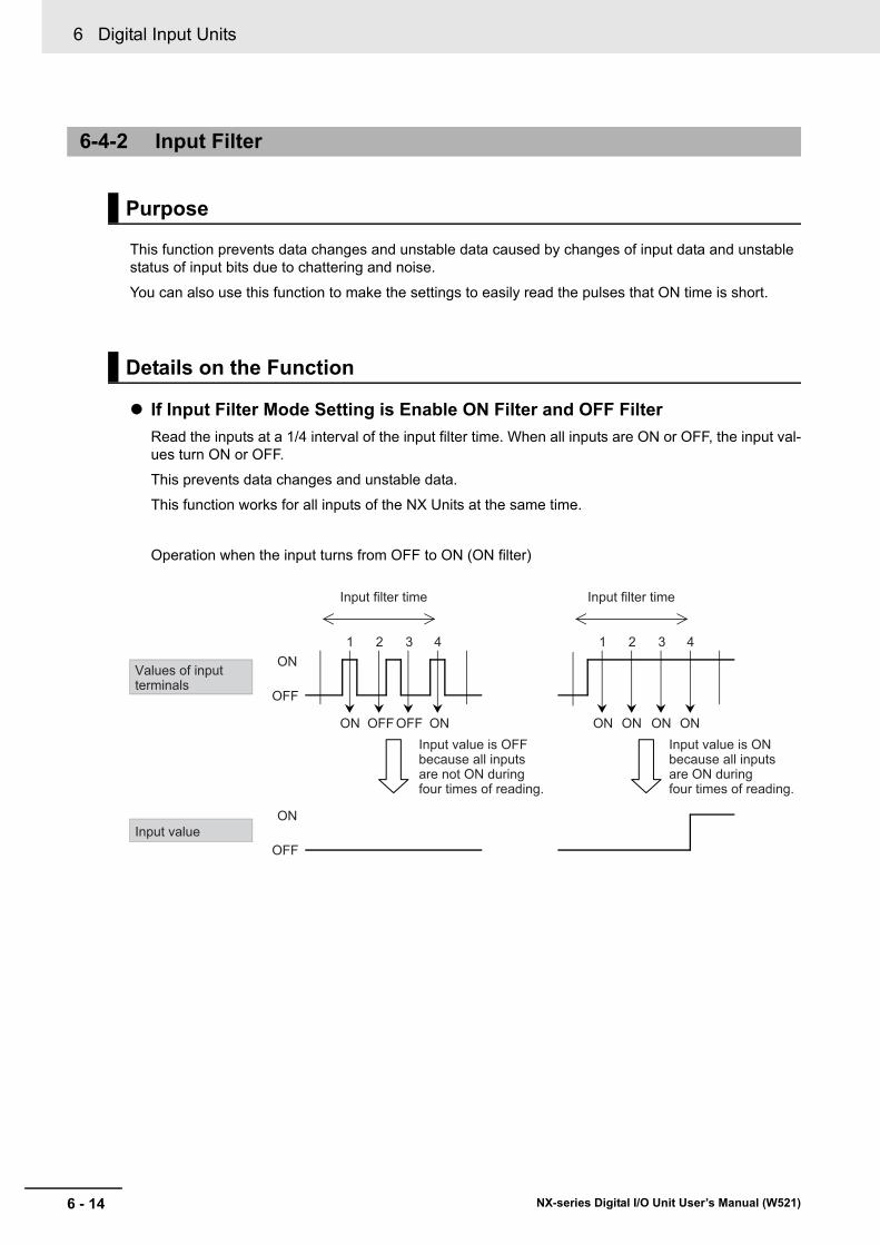
6 Digital Input Units
6 - 14 NX-series Digital I/O Unit User’s Manual (W521)
This function prevents data changes and unstable data caused by changes of input data and unstable status of input bits due to chattering and noise.
You can also use this function to make the settings to easily read the pulses that ON time is short.
If Input Filter Mode Setting is Enable ON Filter and OFF FilterRead the inputs at a 1/4 interval of the input filter time. When all inputs are ON or OFF, the input val-ues turn ON or OFF.
This prevents data changes and unstable data.
This function works for all inputs of the NX Units at the same time.
Operation when the input turns from OFF to ON (ON filter)
6-4-2 Input Filter
Purpose
Details on the Function
Input filter time
Input value is OFF because all inputsare not ON during four times of reading.
Input filter time
Values of input terminals
Input value
1 2 3 4
ON OFF OFF ON
1 2 3 4
ON ON ON ON
OFF
ON
OFF
ON
Input value is ONbecause all inputsare ON during four times of reading.

6 - 15
6 Digital Input Units
NX-series Digital I/O Unit User’s Manual (W521)
6-4 Function
6
6-4-2 Input Filter
Operation when the input turns from ON to OFF (OFF filter)
If Input Filter Mode Setting is Enable Only OFF FilterON filter is disabled and OFF filter is enabled.
This makes easily to read the pulses that ON time is short.
1 2 3 4
OFF ON OFF OFF
1 2 3 4
OFF OFF OFF OFF
OFF
ON
OFF
ON
Input filter time
Input value is ONbecause all inputsare not OFF during four times of reading.
Input filter time
Values of input terminals
Input value
Input value is OFFbecause all inputsare OFF during four times of reading.
Input filter time
1 2 3 4
ON OFF OFF OFF
OFF
ON
OFF
ON
Input filter time
1 2 3 4
ON ON OFF OFF
OFF
ON
OFF
ON
OFFOFFOFF OFF
When input is ON (ON filter disabled) If the status of input terminals turns ON, the input value will turn ON immediately.
When input is OFF (OFF filter enabled)
When input is ON (ON filter disabled) If the status of input terminals turns ON, the input value will turn ON immediately.
When input is OFF (OFF filter enabled)
Values of input terminals
Input value
If the status of input terminals does not turn ON again during the input filter time, the input value will turn OFF after the input filter time has passed.
If the status of input terminals turns ON again during the input filter time, the input value stays ON from that time during the input filter time.

6 Digital Input Units
6 - 16 NX-series Digital I/O Unit User’s Manual (W521)
You can use this function to set the following parameters.
• Input Filter Value Setting• Input Filter Mode Setting
The values you can set for the Input Filter Value Setting depend on the model of Digital Input Units.
Target Units Setting name DescriptionDefault value *1
*1. If a value is set for the input filter time that is smaller than the default value, incorrect input caused by external noises occurs more easily. If an incorrect input occurs, either change the setting to make a long input filter time or take countermeasures, such as separate the Unit or signal lines and noise source, or protect the Unit or signal lines.
Unit
Input Units and Mixed I/O Units in which input ON/OFF response time exceeds 1 μs.
Input Filter Value Setting
Set the filter time for input signals.0: No Filter1: 0.25 ms2: 0.5 ms3: 1 ms4: 2 ms5: 4 ms6: 8 ms7: 16 ms8: 32 ms9: 64 ms10: 128 ms11: 256 ms
3 ---
Input Units and Mixed I/O Units in which input ON/OFF response time is 1 μs maxi-mum.
Set the filter time for input signals.0: No Filter1: 1 μs2: 2 μs3: 4 μs4: 8 μs5: 16 μs6: 32 μs7: 64 μs8: 128 μs9: 256 μs
4 ---
All Units Input Filter Mode Setting
Set the operating mode for the filter.0: Enable ON Filter and OFF Filter1: Enable Only OFF Filter
0 ---

6 - 17
6 Digital Input Units
NX-series Digital I/O Unit User’s Manual (W521)
6-4 Function
6
6-4-2 Input Filter
The Digital Input Units that support switching Free-Run refreshing and Synchronous I/O refreshing.
You cannot use this function for the NX Units that support input refreshing with input changed time.
This section describes how to configure settings with the Sysmac Studio.
When you are using Support Software other than the Sysmac Studio, in the Edit Unit Operation Set-tings Tab Page, set the parameters described in the procedure and transfer the settings to the target NX Unit.
For details on how to display the Edit Unit Operation Settings Tab Page and to transfer settings to an NX Unit with Support Software other than the Sysmac Studio, refer to the operation manual for the Sup-port Software that you are using.
1 Display the Edit Unit Operation Settings Tab Page.
For the display methods, refer to A-9 Displaying the Edit Unit Operation Settings Tab Page on page A-164.
2 Select the filter time you want to set from the upper list of Input Filter Setting.
3 Select the input filter mode you want to set from the lower list of Input Filter Setting.
Target NX Units
Setting Method

6 Digital Input Units
6 - 18 NX-series Digital I/O Unit User’s Manual (W521)
Additional Information
• If you set a value different from the default value, the Value on the Sysmac Studio is dis-played in a different color.
• You can click the Return to Default Value Button to return all set values on the Sysmac Stu-dio to the default values.
• Help for the settings is displayed at the bottom of the Edit Unit Operation Settings Tab Page.
4 Click the Transfer to Unit Button.
The settings are transferred from the Sysmac Studio to the NX Unit.
The settings are reflected after the Unit is restarted.
Precautions for Safe Use
The Unit is required to restart after the transfer of Unit operation settings on the Support Soft-ware is completed. Always sufficiently check the safety at the connected devices before you transfer the Unit operation settings.
Note that when you use this function, the time for which the input value actually turns ON or turns OFF is delayed from the initial input to the input terminals until ON delay time or OFF delay time in the follow-ing table.
Precautions
Delay time DescriptionON delay time ON response time + input filter time OFF delay time OFF response time + input filter time

7 - 1
7
NX-series Digital I/O Unit User’s Manual (W521)
This section describes the types and functions of Digital Output Units and points to con-sider when these Units are used.
7-1 Types of Digital Output Units . . . . . . . . . . . . . . . . . . . . . . . . . . . . . . . . . . . . 7-27-2 Specifications of I/O Data . . . . . . . . . . . . . . . . . . . . . . . . . . . . . . . . . . . . . . . 7-5
7-2-1 Allocable I/O Data . . . . . . . . . . . . . . . . . . . . . . . . . . . . . . . . . . . . . . . . . . . . . . . 7-5
7-3 List of Settings . . . . . . . . . . . . . . . . . . . . . . . . . . . . . . . . . . . . . . . . . . . . . . . . 7-97-4 Function . . . . . . . . . . . . . . . . . . . . . . . . . . . . . . . . . . . . . . . . . . . . . . . . . . . . 7-12
7-4-1 List of Digital Output Unit Functions . . . . . . . . . . . . . . . . . . . . . . . . . . . . . . . . 7-127-4-2 Load Rejection Output Setting . . . . . . . . . . . . . . . . . . . . . . . . . . . . . . . . . . . . 7-137-4-3 Load Short-circuit Protection . . . . . . . . . . . . . . . . . . . . . . . . . . . . . . . . . . . . . 7-17
7-5 Push-pull Output . . . . . . . . . . . . . . . . . . . . . . . . . . . . . . . . . . . . . . . . . . . . . 7-197-6 Precautions when Using the Relay Output Units . . . . . . . . . . . . . . . . . . . 7-20
Digital Output Units

7 Digital Output Units
7 - 2 NX-series Digital I/O Unit User’s Manual (W521)
7-1 Types of Digital Output Units
Digital Input Units are parts of NX Units, and process outputs of digital signals (ON/OFF signals).
The Digital Output Unit types are described below.
Transistor Output Units (Screwless Clamping Terminal Block, 12 mm Width)
Model
Number of
points
Internal I/O common
Maximum value of load cur-
rent
Rated volt-age
I/O refresh-ing method
ON/OFF response
timeReference
NX-OD21542 points
NPN
0.5 A/point, 1 A/Unit 24 VDC
Output refreshing with speci-fied time stamp only
300 ns max./300 ns max.
P. A-40
NX-OD2258 PNP P. A-42
NX-OD3121
4 points
NPN
0.5 A/point, 2 A/Unit
12 to 24 VDC
Switching Synchro-nous I/O refreshing and Free-Run refreshing
0.1 ms max./0.8 ms max.
P. A-44
NX-OD3153
24 VDC
300 ns max./300 ns max.
P. A-46
NX-OD3256
PNP
0.5 ms max./1.0 ms max.
P. A-48
NX-OD3257300 ns max./300 ns max.
P. A-50
NX-OD3268 2 A/point, 8 A/Unit
0.5 ms max./1.0 ms max.
P. A-52
NX-OD41218 points
NPN
0.5 A/point, 4 A/Unit
12 to 24 VDC
0.1 ms max./0.8 ms max.
P. A-54
NX-OD4256 PNP 24 VDC0.5 ms max./1.0 ms max.
P. A-56
NX-OD512116 points
NPN 12 to 24 VDC
0.1 ms max./0.8 ms max.
P. A-58
NX-OD5256 PNP 24 VDC0.5 ms max./1.0 ms max.
P. A-60

7 - 3
7 Digital Output Units
NX-series Digital I/O Unit User’s Manual (W521)
7-1 Types of Digital O
utput Units
7
Transistor Output Units (M3 Screw Terminal Block, 30 mm Width)
ModelNum-ber of points
Internal I/O common
Maximum value of load cur-
rent
Rated volt-age
I/O refresh-ing method
ON/OFF response
time
Refer-ence
NX-OD5121-1
16 points
NPN
0.5 A/point, 5 A/Unit
12 to 24 VDC
Switching Synchro-nous I/O refreshing and Free-Run refreshing
0.1 ms max./0.8 ms max.
P. A-62
NX-OD5256-1 PNP 24 VDC0.5 ms max./1.0 ms max.
P. A-64
Transistor Output Units (MIL Connector, 30 mm Width)
ModelNum-ber of points
Internal I/O common
Maximum value of load cur-
rent
Rated volt-age
I/O refresh-ing method
ON/OFF response
time
Refer-ence
NX-OD5121-516 points
NPN0.5 A/point, 2 A/Unit
12 to 24 VDC
Switching Synchro-nous I/O refreshing and Free-Run refreshing
0.1 ms max./0.8 ms max.
P. A-66
NX-OD5256-5 PNP 24 VDC0.5 ms max./1.0 ms max.
P. A-68
NX-OD6121-532 points
NPN 0.5 A/point, 2 A/com-mon, 4 A/Unit
12 to 24 VDC
0.1 ms max./0.8 ms max.
P. A-70
NX-OD6256-5 PNP 24 VDC0.5 ms max./1.0 ms max.
P. A-72
Transistor Output Units (Fujitsu Connector, 30 mm Width)
ModelNum-ber of points
Internal I/O common
Maximum value of load cur-
rent
Rated volt-age
I/O refresh-ing method
ON/OFF response
time
Refer-ence
NX-OD6121-6 32 points NPN
0.5 A/point, 2 A/com-mon, 4 A/Unit
12 to 24 VDC
Switching Synchro-nous I/O refreshing and Free-Run refreshing
0.1 ms max./0.8 ms max.
P. A-74

7 Digital Output Units
7 - 4 NX-series Digital I/O Unit User’s Manual (W521)
Relay Output Units (Screwless Clamping Terminal Block, 12 mm Width)
Model
Number of
points
Relay type Maximum switching capacity
I/O refresh-ing method
ON/OFF response
timeReference
NX-OC2633 2 points
N.O. 250 VAC/2 A (cosΦ = 1), 250 VAC/2 A (cosΦ = 0.4), 24 VDC/2 A,4 A/Unit
Free-Run refreshing
15 ms max./15 ms max.
P. A-76
NX-OC2733 N.O. + N.C. P. A-78
Relay Output Units (Screwless Clamping Terminal Block, 24 mm Width)
Model
Number of
points
Relay type Maximum switching capacity
I/O refresh-ing method
ON/OFF response
timeReference
NX-OC46338 points
N.O.
250 VAC/2A (cosφ=1),250 VAC/2A (cosφ=0.4),24 VDC/2A, 8 A/Unit
Free-Runrefreshing
15 msmax./15 msmax.
P. A-80

7 - 5
7 Digital Output Units
NX-series Digital I/O Unit User’s Manual (W521)
7-2 Specifications of I/O D
ata
7
7-2-1 Allocable I/O
Data
7-2 Specifications of I/O Data
This section describes I/O data for the Digital Output Units.
This section describes the allocable I/O data in the Digital Output Unit.
An I/O entry mapping is assigned to the I/O allocation settings for the Digital Output Unit except the Unit that supports output refreshing with specified time stamp.
In the Unit that supports output refreshing with specified time stamp, one I/O entry mapping for input and one I/O entry mapping for output are assigned.
A specific I/O entry is assigned to the I/O entry mapping for each NX Unit model. These allocations are fixed, so you cannot add others or change them.
An I/O entry means the I/O data described in this section. An I/O entry mapping means a collection of I/O entries.
To assign the I/O allocation information of the NX Unit or Slave Terminal to an NJ/NX-series CPU Unit or NY-series Industrial PC, use the I/O ports for the allocated I/O data.
However, for Slave Terminals, I/O ports may not be used depending on the type of communications master or Communications Coupler Unit.
Refer to the user’s manual for the connected Communications Coupler Unit for details on how to use I/O data for Slave Terminals.
Two-point Output Units
7-2-1 Allocable I/O Data
NX Units in Free-Run Refreshing or Synchronous I/O Refreshing
Data name Description Data type
Default value
I/O port name Index Subin-
dexOutput Bit 00 The output set value for
output bit 00.BOOL FALSE Output Bit 00 7000 hex 01 hex
Output Bit 01 The output set value for output bit 01.
BOOL FALSE Output Bit 01 02 hex

7 Digital Output Units
7 - 6 NX-series Digital I/O Unit User’s Manual (W521)
Four-point Output Units
Eight-point Output Units
Data name Description Data type
Default value
I/O port name Index Subin-
dexOutput Bit 00 The output set value for
output bit 00.BOOL FALSE Output Bit 00 7000 hex 01 hex
Output Bit 01 The output set value for output bit 01.
BOOL FALSE Output Bit 01 02 hex
Output Bit 02 The output set value for output bit 02.
BOOL FALSE Output Bit 02 03 hex
Output Bit 03 The output set value for output bit 03.
BOOL FALSE Output Bit 03 04 hex
Data name Description Data type
Default value
I/O port name Index Subin-
dexOutput Bit 8 bits The output values for 8
bits.
The following 8 BOOL data are included.
BYTE 00 hex Output Bit 8 bits
7001 hex 01 hex
Output Bit 00 The output set value for output bit 00.
BOOL FALSE Output Bit 00
Output Bit 01 The output set value for output bit 01.
BOOL FALSE Output Bit 01
Output Bit 02 The output set value for output bit 02.
BOOL FALSE Output Bit 02
Output Bit 03 The output set value for output bit 03.
BOOL FALSE Output Bit 03
Output Bit 04 The output set value for output bit 04.
BOOL FALSE Output Bit 04
Output Bit 05 The output set value for output bit 05.
BOOL FALSE Output Bit 05
Output Bit 06 The output set value for output bit 06.
BOOL FALSE Output Bit 06
Output Bit 07 The output set value for output bit 07.
BOOL FALSE Output Bit 07

7 - 7
7 Digital Output Units
NX-series Digital I/O Unit User’s Manual (W521)
7-2 Specifications of I/O D
ata
7
7-2-1 Allocable I/O
Data
Sixteen-point Output Units
Thirty-two-point Output Units
Data name Description Data type
Default value
I/O port name Index Subin-
dexOutput Bit 16 bits The output values for 16
bits.
The following 16 BOOL data are included.
WORD 0000 hex Output Bit 16 bits
7002 hex 01 hex
Output Bit 00 The output set value for output bit 00.
BOOL FALSE Output Bit 00
Output Bit 01 The output set value for output bit 01.
BOOL FALSE Output Bit 01
•
•
•Output Bit 15 The output set value for
output bit 15.BOOL FALSE Output Bit 15
Data name Description Data type
Default value
I/O port name Index Subin-
dexOutput Bit 32 bits The output values for 32
bits.
The following 32 BOOL data are included.
DWORD 00000000 hex
Output Bit 32 bits
7003 hex 01 hex
Output Bit 00 The output set value for output bit 00.
BOOL FALSE Output Bit 00
Output Bit 01 The output set value for output bit 01.
BOOL FALSE Output Bit 01
•
•
•Output Bit 31 The output set value for
output bit 31.BOOL FALSE Output Bit 31

7 Digital Output Units
7 - 8 NX-series Digital I/O Unit User’s Manual (W521)
Two-point Output Units
NX Units in Output Refreshing with Specified Time Stamp
Data name Description Data type
Default value
I/O port name Index Subin-
dex Unit
Output Bit 00 The output set value for output bit 00.
BOOL FALSE Output Bit 00 7000 hex 01 hex ---
Output Bit 01 The output set value for output bit 01.
BOOL FALSE Output Bit 01 02 hex ---
Output Bit 00 Time Stamp
The specified oper-ation time for out-put bit 00. If the value is 0, the out-put is refreshed immediately.
ULINT 0 Output Bit 00 Time Stamp
7010 hex 01 hex ns
Output Bit 01 Time Stamp
The specified oper-ation time for out-put bit 01. If the value is 0, the out-put is refreshed immediately.
ULINT 0 Output Bit 01 Time Stamp
02 hex ns
Output Bit 00 Out-put Status
The specified time output status for output bit 00.
BOOL FALSE Output Bit 00 Output Sta-tus
6011 hex 01 hex ---
Output Bit 01 Out-put Status
The specified time output status for output bit 01.
BOOL FALSE Output Bit 01 Output Sta-tus
02 hex ---

7 - 9
7 Digital Output Units
NX-series Digital I/O Unit User’s Manual (W521)
7-3 List of Settings
7
7-3 List of Settings
The followings are the setting descriptions, setting ranges, and default values of the functions that can be used in the Digital Output Units.
The settings are reflected after the Unit is restarted.
Precautions for Safe Use
The Unit is required to restart after the transfer of Unit operation settings on the Support Soft-ware is completed. Always sufficiently check the safety at the connected devices before you transfer the Unit operation settings.
Two-point Output Units
Four-point Output Units
NX Units in Free-Run Refreshing or Synchronous I/O Refreshing
Setting name Description Default value
Setting range Unit Index Subin-
dexRefer-ence
Load Rejection Output for Output Bit 00
Set the output at load OFF.
FALSE: OFFTRUE: Hold the present value.
FALSE TRUE or FALSE
--- 5010 hex
01 hex P. 7-13
Load Rejection Output for Output Bit 01
FALSE TRUE or FALSE
--- 02 hex
Load Rejection Output for Output Bit 02
FALSE TRUE or FALSE
--- 03 hex
Load Rejection Output for Output Bit 03
FALSE TRUE or FALSE
--- 04 hex

7 Digital Output Units
7 - 10 NX-series Digital I/O Unit User’s Manual (W521)
Eight-point Output Units
Sixteen-point Output Units
Setting name Description Default value
Setting range Unit Index Subin-
dexRefer-ence
Load Rejection Output for Output Bit (8 bits)
Set the output at load OFF in units of 8 bits.
Bit 0: Setting for output bit 00Bit 1: Setting for output bit 01Bit 2: Setting for output bit 02Bit 3: Setting for output bit 03Bit 4: Setting for output bit 04Bit 5: Setting for output bit 05Bit 6: Setting for output bit 06Bit 7: Setting for output bit 07
FALSE: OFFTRUE: Hold the present value.
00 hex 00 to FF hex
--- 5011 hex
01 hex P. 7-13
Setting name Description Default value
Setting range Unit Index Subin-
dexRefer-ence
Load Rejection Output for Output Bit (16 bits)
Set the output at load OFF in units of 16 bits.
Bit 0: Setting for output bit 00Bit 1: Setting for output bit 01
•
•
•
Bit 15: Setting for output bit 15
FALSE: OFFTRUE: Hold the present value.
0000 hex
0000 to FFFF hex
--- 5012 hex
01 hex P. 7-13

7 - 11
7 Digital Output Units
NX-series Digital I/O Unit User’s Manual (W521)
7-3 List of Settings
7
Thirty-two-point Output Units
Two-point Output Units
Setting name Description Default value
Setting range Unit Index Subin-
dexRefer-ence
Load Rejection Output for Output Bit (32 bits)
Set the output at load OFF in units of 32 bits.
Bit 0: Setting for output bit 00Bit 1: Setting for output bit 01
•
•
•
Bit 31: Setting for output bit 31
FALSE: OFFTRUE: Hold the present value.
00000000 hex
00000000 to FFFFFFFF hex
--- 5013 hex
01 hex P. 7-13
NX Units in Output Refreshing with Specified Time Stamp
Setting name Description Default value
Setting range Unit Index Subin-
dexRefer-ence
Load Rejection Output for Output Bit 00
Set the output at load OFF.
FALSE: OFFTRUE: Hold the present value.
FALSE TRUE or FALSE
--- 5010 hex
01 hex P. 7-13
Load Rejection Output for Output Bit 01
FALSE TRUE or FALSE
--- 02 hex

7 Digital Output Units
7 - 12 NX-series Digital I/O Unit User’s Manual (W521)
7-4 Function
This section describes the Digital Output Unit functions.
Refer to the specifications of each model in A-1 Data Sheet on page A-2 for details on the functions.
7-4-1 List of Digital Output Unit Functions
Function name Description ReferenceFree-Run Refreshing With this I/O refreshing method, the refresh cycle of the NX
bus and the I/O refresh cycles of the NX Units are asynchro-nous.
5-2-4 Free-Run Refreshing on page 5-8
Synchronous I/O Refresh-ing
With this I/O refreshing method, the timing to read inputs or to refresh outputs is synchronized on a fixed interval between more than one NX Unit connected to a CPU Unit.
In addition, with this I/O refreshing method, the timing to read inputs or to refresh outputs is synchronized on a fixed interval between more than one NX Unit on more than one Slave Ter-minal.
5-2-6 Synchro-nous Output Refreshing on page 5-16
Time Stamp Refreshing With this I/O refreshing method, the NX Units record the DC times when inputs change or perform outputs at specified DC times. These times are not synchronized to the NX bus refresh cycles.
Data exchange between the NX Units and the CPU Unit and data exchange between the NX Units and the EtherCAT Cou-pler Unit are performed cyclically on the NX bus refresh cycles.
5-2-7 Time Stamp Refreshing on page 5-19
Output refreshing with specified time stamp
With this I/O refreshing method, the Output Units refresh out-puts at specified DC times.
5-2-9 Output Refreshing with Specified Time Stamp on page 5-27
Load Rejection Output Setting
A function that performs the preset output operation when the Digital Output Unit cannot receive output data due to an NX bus error or CPU Unit watchdog timer error, in the case of Units connected to a CPU Unit.
A function that performs the preset output operation when the Digital Output Unit cannot receive output data due to a host error on the Communications Coupler Unit or an error on the NX bus, in the case of Slave Terminals.
7-4-2 Load Rejec-tion Output Setting on page 7-13
Load Short-circuit Protec-tion
A function in which the output will turn OFF to protect the out-put circuit when an overload or load short-circuit occurs due to a failure of the connected external devices.
7-4-3 Load Short-circuit Pro-tection on page 7-17

7 - 13
7 Digital Output Units
NX-series Digital I/O Unit User’s Manual (W521)
7-4 Function
7
7-4-2 Load Rejection O
utput Setting
This function maintains a safe output status by performing the preset output operations when the Digital Output Unit connected to the CPU Unit cannot receive output data from the CPU Unit due to an NX bus error or CPU Unit watchdog timer error.
For Slave Terminals, this function maintains a safe output status by performing the preset output operations when Digital Output Units cannot receive the output data from the Communications Coupler Unit due to a host error on the Communications Coupler Unit or an error on the NX bus.
Sets whether to hold the output or turn it OFF when an error occurred.
Each output bit can be set independently.
Two-point Output Units
Four-point Output Units
7-4-2 Load Rejection Output Setting
Purpose
Details on the Function
Setting name Description Default value Unit
Load Rejection Output for Output Bit 00
Set the output at load OFF.
FALSE: OFFTRUE: Hold the present value.
FALSE ---
Load Rejection Output for Output Bit 01
FALSE ---
Setting name Description Default value Unit
Load Rejection Output for Output Bit 00
Set the output at load OFF.
FALSE: OFFTRUE: Hold the present value.
FALSE ---
Load Rejection Output for Output Bit 01
FALSE ---
Load Rejection Output for Output Bit 02
FALSE ---
Load Rejection Output for Output Bit 03
FALSE ---
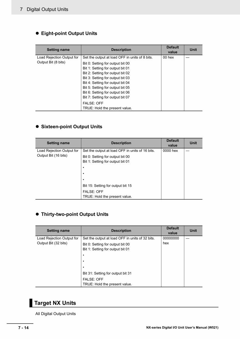
7 Digital Output Units
7 - 14 NX-series Digital I/O Unit User’s Manual (W521)
Eight-point Output Units
Sixteen-point Output Units
Thirty-two-point Output Units
All Digital Output Units
Setting name Description Default value Unit
Load Rejection Output for Output Bit (8 bits)
Set the output at load OFF in units of 8 bits.
Bit 0: Setting for output bit 00Bit 1: Setting for output bit 01Bit 2: Setting for output bit 02Bit 3: Setting for output bit 03Bit 4: Setting for output bit 04Bit 5: Setting for output bit 05Bit 6: Setting for output bit 06Bit 7: Setting for output bit 07
FALSE: OFFTRUE: Hold the present value.
00 hex ---
Setting name Description Default value Unit
Load Rejection Output for Output Bit (16 bits)
Set the output at load OFF in units of 16 bits.
Bit 0: Setting for output bit 00Bit 1: Setting for output bit 01
•
•
•
Bit 15: Setting for output bit 15
FALSE: OFFTRUE: Hold the present value.
0000 hex ---
Setting name Description Default value Unit
Load Rejection Output for Output Bit (32 bits)
Set the output at load OFF in units of 32 bits.
Bit 0: Setting for output bit 00Bit 1: Setting for output bit 01
•
•
•
Bit 31: Setting for output bit 31
FALSE: OFFTRUE: Hold the present value.
00000000 hex
---
Target NX Units

7 - 15
7 Digital Output Units
NX-series Digital I/O Unit User’s Manual (W521)
7-4 Function
7
7-4-2 Load Rejection O
utput Setting
This section describes how to configure settings with the Sysmac Studio.
When you are using Support Software other than the Sysmac Studio, in the Edit Unit Operation Set-tings Tab Page, set the parameters described in the procedure and transfer the settings to the target NX Unit.
For details on how to display the Edit Unit Operation Settings Tab Page and to transfer settings to an NX Unit with Support Software other than the Sysmac Studio, refer to the operation manual for the Sup-port Software that you are using.
1 Display the Edit Unit Operation Settings Tab Page.
For the display methods, refer to A-9 Displaying the Edit Unit Operation Settings Tab Page on page A-164.
2 Make the following settings according to the type of NX Unit you want to set.
Two-point or Four-point Output Unit (Data type: BOOL)
Select False (OFF) or True (Hold the present value) from the list of Load Rejection Output Setting for which the output bit you want to set.
Eight-point, Sixteen-point, and Thirty-two-point Output Units
Enter a set value in the Value text box. The data type of the set values and the range of the values that you can set vary depending on the number of output points.
Setting Method
Number of output points Data type Set value8 points USINT 0 to 25516 points UINT 0 to 6553532 points UDINT 0 to 4294967295

7 Digital Output Units
7 - 16 NX-series Digital I/O Unit User’s Manual (W521)
Additional Information
• If you set a value different from the default value, the Value on the Sysmac Studio is dis-played in a different color.
• You can click the Return to Default Value Button to return all set values on the Sysmac Stu-dio to the default values.
• Help for the settings is displayed at the bottom of the Edit Unit Operation Settings Tab Page.
3 Click the Transfer to Unit Button.
The settings are transferred from the Sysmac Studio to the NX Unit.
The settings are reflected after the Unit is restarted.
Precautions for Safe Use
The Unit is required to restart after the transfer of Unit operation settings on the Support Soft-ware is completed. Always sufficiently check the safety at the connected devices before you transfer the Unit operation settings.

7 - 17
7 Digital Output Units
NX-series Digital I/O Unit User’s Manual (W521)
7-4 Function
7
7-4-3 Load Short-circuit Protection
This function is used to protect the output circuits of the Digital Output Units when an external connec-tion load short-circuit occurs.
As shown in the figure below, normally when the output bit (OUT) turns ON, the transistor turns ON and then output current (Iout) will flow.
The transistor of the Transistor Output Units generates heat when output current (Iout) flows.
If an overload or short-circuit occurs, causing the output current (lout) to exceed the maximum value of load current as shown in the figure below and the junction temperature (Tj) of the transistor to reach the thermal shutdown temperature (Tstd) in which a load short-circuit protection operates, the output will turn OFF to protect the transistor from being damaged.
When the junction temperature (Tj) of the transistor drops down to the reset temperature (Tr), the out-put OFF will be automatically reset and the output current will start flowing.
7-4-3 Load Short-circuit Protection
Purpose
Details on the Function
OUT
OFF
ON
OFF
ONMaximum load current
Iout OUT : Output bitIout : Output current
OUT : Output bitIout : Output currentTj : Junction temperature of transistorTstd : Thermal shutdown temperatureTr : Reset temperature
OUT
OFF
ON
OFF
ON
Iout
Tj = TstdTj = Tr
Tj = Tstd
Maximum load current

7 Digital Output Units
7 - 18 NX-series Digital I/O Unit User’s Manual (W521)
Restrictions on UseThe load short-circuit protection function only protects internal circuits for a short period.
As shown in the figure above, the load short-circuit protection of this NX Unit is automatically released when the Tj equals to Tr.
Therefore, unless the cause of short-circuit is removed, ON/OFF operations are repeated in the out-put.
If the short-circuit is not corrected, output elements deteriorate. If any external load is short-circuited, immediately turn OFF the applicable output and remove the cause of the short-circuit.
Digital Output Units of PNP outputs
No setting is required.
Target NX Units
Setting Method

7 - 19
7 Digital Output Units
NX-series Digital I/O Unit User’s Manual (W521)
7-5 Push-pull Output
7
7-5 Push-pull Output
The Digital Output Units with the ON/OFF response time of 1 μs or less use a push-pull output to increase the speed of the output ON/OFF response.
For this type of the Output Units, use the single load power supply for the I/O power and connected external devices.
If multiple power supplies are used, the current may flow into the output bits via the diodes built in the I/O circuit and cause the Output Units to malfunction.
Good Example
Bad Example
Three-wire device
Additional I/O PowerSupply Unit
Transistor Output Unit
Additional I/O Power Supply
Unit
TransistorOutput Unit
24 VDC
Three-wiresensor
IOV
IOG
IOV
IOG
IOV
IOG
IOV
IOG
0
IOG
IOV
IOV
A1 B1
A8 B8
2
IOG
1
IOG
IOV
IOV
3
IOG
IOV
IOG
28.8V DC
A1 B1
A8 B8
24 VDC
IOV
IOG
IOV
IOG
IOV
IOG
IOV
IOG
IOV
IOG
0
IOG
IOV
IOV
A1 B1
A8 B8
2
IOG
1
IOG
IOV
IOV
3
IOG
OV2
IOGOG
IOGV
B11
IO
Three-wire device
Additional I/O Power Supply
Unit
TransistorOutput Unit
24 VDC
Three-wiresensor
28.8V DC 24 VDC
Additional I/O PowerSupply Unit
Transistor Output Unit
A1 B1
A8 B8
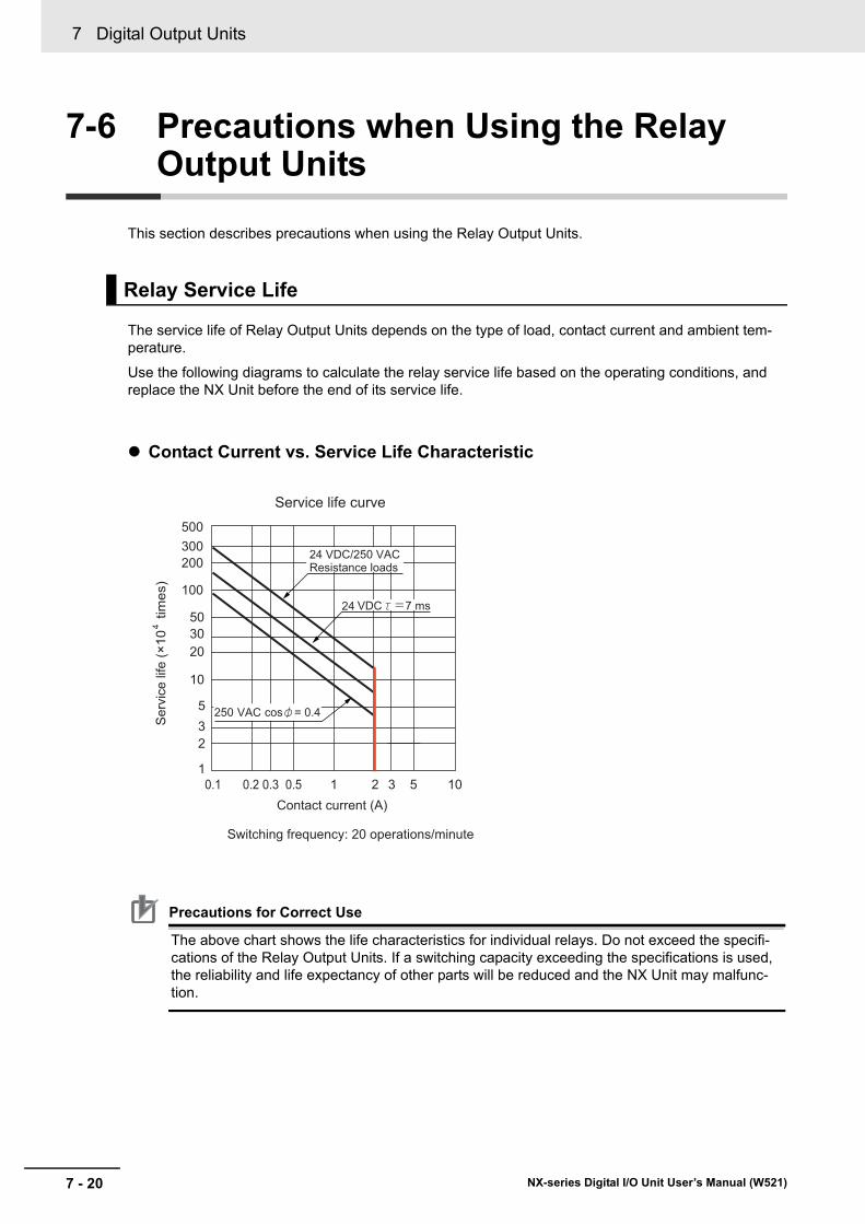
7 Digital Output Units
7 - 20 NX-series Digital I/O Unit User’s Manual (W521)
7-6 Precautions when Using the Relay Output Units
This section describes precautions when using the Relay Output Units.
The service life of Relay Output Units depends on the type of load, contact current and ambient tem-perature.
Use the following diagrams to calculate the relay service life based on the operating conditions, and replace the NX Unit before the end of its service life.
Contact Current vs. Service Life Characteristic
Precautions for Correct Use
The above chart shows the life characteristics for individual relays. Do not exceed the specifi-cations of the Relay Output Units. If a switching capacity exceeding the specifications is used, the reliability and life expectancy of other parts will be reduced and the NX Unit may malfunc-tion.
Relay Service Life
Serv
ice
life
(×10
tim
es)
4
Switching frequency: 20 operations/minute
500300200
100
503020
532
1105321
10
0.50.30.20.1Contact current (A)
Service life curve
24 VDC/250 VAC Resistance loads
24
VAC

7 - 21
7 Digital Output Units
NX-series Digital I/O Unit User’s Manual (W521)
7-6 Precautions when U
sing the Relay O
utput Units
7
The life of the Relay varies with the load inductance.
If any inductive load is used, we recommend that you use a contact protection circuit. (Contact Protec-tion Circuit on page 7-21).
Be sure to connect a contact protection circuit in parallel with every DC inductive load that is connected to the Contact Output Unit because the usage of a contact protection circuit has a significant effect on the service life of the contact.
Contact protection circuits are used with the Contact Output Unit in order to prolong the life of each relay mounted to the Contact Output Unit, prevent noise, and reduce the generation of carbide and nitrate deposits caused by arcs. However, if contact protection circuits are used incorrectly, they can reduce relay service life. Using a contact protection circuit can also cause a delay in the resetting time (shut-off time).
Contact protection circuit examples are listed in the following table.
Inductive Load
Contact Protection Circuit
CircuitCurrent
Feature Required elementAC DC
CR method
Yes Yes If the load is a relay or solenoid, there is a delay in the resetting time.If the power supply volt-age is 24 or 48 V, con-nect the contact protection circuit in paral-lel with the load. If the supply voltage is 100 to 200 V, connect the con-tact protection circuit between the contacts.
The capacitance of the capaci-tor should be approx. 1 to 0.5 μF per contact current of 1 A and resistance of the resistor should be approx. 0.5 to 1 Ω per contact voltage of 1 V.C: The capacitance of the capacitor should be approx. 0.5 to 1 μF per contact current of 1 A.R: The resistance of the resis-tor should be approx. 0.5 to 1 Ω per contact voltage of 1 V.These values, however, vary depending on the load and the characteristics of the relay.Decide these values from experiments, and take into con-sideration that the capacitance suppresses spark discharge when the contacts are sepa-rated and the resistance restricts the current that flows into the load when the circuit is closed again.The dielectric strength of the capacitor must be 200 to 300 V. If the circuit is an AC circuit, use a capacitor with no polarity.
Powersupply
C
R Indu
ctiv
elo
ad

7 Digital Output Units
7 - 22 NX-series Digital I/O Unit User’s Manual (W521)
Diode method
× Yes The diode connected in parallel with the load changes energy accu-mulated by the coil into a current, which then flows into the coil so that the current will be converted into Joule heat by the resistance of the induc-tive load.The delay in resetting time caused by this method is longer than that caused by the CR method.
The reversed dielectric strength value of the diode must be at least 10 times as large as the circuit voltage value. The for-ward current of the diode must be the same as or larger than the load current.The reversed dielectric strength value of the diode may be two to three times larger than the power supply voltage if the con-tact protection circuit is applied to electronic circuits with low circuit voltages.
Varistor method
Yes Yes The varistor method pre-vents the imposition of high voltage between the contacts by using the constant voltage charac-teristic of the varistor. There is a delay in the resetting time.If the power supply volt-age is 24 to 48 V, insert the varistor in parallel with the load. If the sup-ply voltage is 100 to 200 V, insert the varistor between the contacts.
-
CircuitCurrent
Feature Required elementAC DC
Powersupply
Indu
ctiv
elo
ad
Powersupply
Indu
ctiv
elo
ad

7 - 23
7 Digital Output Units
NX-series Digital I/O Unit User’s Manual (W521)
7-6 Precautions when U
sing the Relay O
utput Units
7
Precautions for Correct Use
Do not connect a contact protection circuit with an inductive load as shown in the diagram below.
This contact protection circuit is very effective for preventing spark discharge when the circuit is opened. However, when the contacts are closed, the contacts may be welded due to the cur-rent charged in the capacitor. DC inductive loads can be more difficult to switch than resistive loads. If an appropriate contact protection circuit is used, however, DC inductive loads are as easy to switch as resistive loads.
Powersupply
Indu
ctiv
elo
ad

7 Digital Output Units
7 - 24 NX-series Digital I/O Unit User’s Manual (W521)

8 - 1
8
NX-series Digital I/O Unit User’s Manual (W521)
This section describes the types and functions of Digital Mixed I/O Units and points to consider when these Units are used.
8-1 Types of Digital Mixed I/O Units . . . . . . . . . . . . . . . . . . . . . . . . . . . . . . . . . . 8-28-2 Specifications of I/O Data . . . . . . . . . . . . . . . . . . . . . . . . . . . . . . . . . . . . . . . 8-3
8-2-1 Allocable I/O Data . . . . . . . . . . . . . . . . . . . . . . . . . . . . . . . . . . . . . . . . . . . . . . . 8-3
8-3 List of Settings . . . . . . . . . . . . . . . . . . . . . . . . . . . . . . . . . . . . . . . . . . . . . . . . 8-58-3-1 Input Settings . . . . . . . . . . . . . . . . . . . . . . . . . . . . . . . . . . . . . . . . . . . . . . . . . . 8-58-3-2 Output Settings . . . . . . . . . . . . . . . . . . . . . . . . . . . . . . . . . . . . . . . . . . . . . . . . . 8-6
8-4 Function . . . . . . . . . . . . . . . . . . . . . . . . . . . . . . . . . . . . . . . . . . . . . . . . . . . . . 8-78-4-1 Input Functions . . . . . . . . . . . . . . . . . . . . . . . . . . . . . . . . . . . . . . . . . . . . . . . . . 8-78-4-2 Output Functions . . . . . . . . . . . . . . . . . . . . . . . . . . . . . . . . . . . . . . . . . . . . . . . 8-7
Digital Mixed I/O Units

8 Digital Mixed I/O Units
8 - 2 NX-series Digital I/O Unit User’s Manual (W521)
8-1 Types of Digital Mixed I/O Units
Digital Mixed I/O Units are parts of NX Units, and process both inputs and outputs of digital signals (ON/OFF signals).
The Digital Mixed I/O Unit types are described below.
DC Input/Transistor Output Units (MIL Connector, 30 mm Width)
ModelNum-ber of points
Internal I/O com-
mon
Maximum value of load cur-
rent
Rated volt-age
I/O refresh-ing method
ON/OFF response
time
Refer-ence
NX-MD6121-5Out-puts: 16 points
Inputs: 16 points
Outputs: NPN
Inputs: For both NPN/PNP
0.5 A/point, 2 A/Unit
Outputs: 12 to 24 VDC
Inputs: 24 VDC
Switching Synchro-nous I/O refreshing and Free-Run refreshing
Outputs: 0.1 ms max./0.8 ms max.
Inputs: 20 μs max./400 μs max.
P. A-84
NX-MD6256-5
Outputs: PNP
Inputs: For both NPN/PNP
Outputs: 24 VDC
Inputs: 24 VDC
Outputs: 0.5 ms max./1.0 ms max.
Inputs: 20 μs max./400 μs max.
P. A-88
DC Input/Transistor Output Units (Fujitsu Connector, 30 mm Width)
ModelNum-ber of points
Internal I/O common
Maximum value of load cur-
rent
Rated volt-age
I/O refresh-ing method
ON/OFF response
time
Refer-ence
NX-MD6121-6
Out-puts: 16 points
Inputs: 16 points
Outputs: NPN
Inputs: For both NPN/PNP
0.5 A/point, 2 A/Unit
Outputs: 12 to 24 VDC
Inputs: 24 VDC
Switching Synchro-nous I/O refreshing and Free-Run refreshing
Outputs: 0.1 ms max./0.8 ms max.
Inputs: 20 μs max./400 μs max.
P. A-92

8 - 3
8 Digital Mixed I/O Units
NX-series Digital I/O Unit User’s Manual (W521)
8-2 Specifications of I/O D
ata
8
8-2-1 Allocable I/O
Data
8-2 Specifications of I/O Data
This section describes I/O data for the Digital Mixed I/O Units.
This section describes the allocable I/O data in the Digital Mixed I/O Units.
An I/O entry mapping is assigned to the I/O allocation settings for the Digital Mixed I/O Units.
A specific I/O entry is assigned to the I/O entry mapping for each NX Unit model. These allocations are fixed, so you cannot add others or change them.
An I/O entry means the I/O data described in this section. An I/O entry mapping means a collection of I/O entries.
To assign the I/O allocation information of the NX Unit or Slave Terminal to an NJ/NX-series CPU Unit or NY-series Industrial PC, use the I/O ports for the allocated I/O data.
However, for Slave Terminals, I/O ports may not be used depending on the type of communications master or Communications Coupler Unit.
Refer to the user’s manual for the connected Communications Coupler Unit for details on how to use I/O data for Slave Terminals.
Thirty-two-point Mixed I/O UnitsInput section
8-2-1 Allocable I/O Data
NX Units in Free-Run Refreshing or Synchronous I/O Refreshing
Data name Description Data type
Default value
I/O port name Index Subin-
dexInput Bit 16 bits The input values for 16
bits.
The following 16 BOOL data are included.
WORD 0000 hex Input Bit 16 bits
6002 hex 01 hex
Input Bit 00 The input value for input bit 00.
BOOL FALSE Input Bit 00
Input Bit 01 The input value for input bit 01.
BOOL FALSE Input Bit 01
•
•
•Input Bit 15 The input value for input
bit 15.BOOL FALSE Input Bit 15

8 Digital Mixed I/O Units
8 - 4 NX-series Digital I/O Unit User’s Manual (W521)
Output section
Data name Description Data type
Default value
I/O port name Index Subin-
dexOutput Bit 16 bits The output values for 16
bits.
The following 16 BOOL data are included.
WORD 0000 hex Output Bit 16 bits
7002 hex 01 hex
Output Bit 00 The output set value for output bit 00.
BOOL FALSE Output Bit 00
Output Bit 01 The output set value for output bit 01.
BOOL FALSE Output Bit 01
•
•
•Output Bit 15 The output set value for
output bit 15.BOOL FALSE Output Bit 15
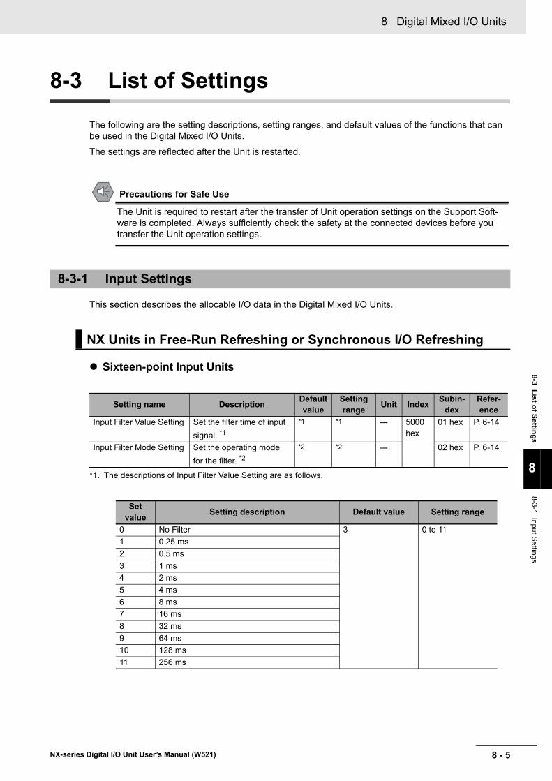
8 - 5
8 Digital Mixed I/O Units
NX-series Digital I/O Unit User’s Manual (W521)
8-3 List of Settings
8
8-3-1 Input Settings
8-3 List of Settings
The following are the setting descriptions, setting ranges, and default values of the functions that can be used in the Digital Mixed I/O Units.
The settings are reflected after the Unit is restarted.
Precautions for Safe Use
The Unit is required to restart after the transfer of Unit operation settings on the Support Soft-ware is completed. Always sufficiently check the safety at the connected devices before you transfer the Unit operation settings.
This section describes the allocable I/O data in the Digital Mixed I/O Units.
Sixteen-point Input Units
*1. The descriptions of Input Filter Value Setting are as follows.
8-3-1 Input Settings
NX Units in Free-Run Refreshing or Synchronous I/O Refreshing
Setting name Description Default value
Setting range Unit Index Subin-
dexRefer-ence
Input Filter Value Setting Set the filter time of input signal. *1
*1 *1 --- 5000 hex
01 hex P. 6-14
Input Filter Mode Setting Set the operating mode for the filter. *2
*2 *2 --- 02 hex P. 6-14
Set value Setting description Default value Setting range
0 No Filter 3 0 to 111 0.25 ms2 0.5 ms3 1 ms4 2 ms5 4 ms6 8 ms7 16 ms8 32 ms9 64 ms10 128 ms11 256 ms

8 Digital Mixed I/O Units
8 - 6 NX-series Digital I/O Unit User’s Manual (W521)
*2. The descriptions of Input Filter Mode Setting are as follows.
Sixteen-point Output Units
Set value Setting description Default value Setting range
0 Enable ON Filter and OFF Filter 0 0/11 Enable Only OFF Filter
8-3-2 Output Settings
NX Units in Free-Run Refreshing or Synchronous I/O Refreshing
Setting name Description Default value
Setting range Unit Index Subin-
dexRefer-ence
Load Rejection Output for Output Bit (16 bits)
Set the output at load OFF in units of 16 bits.
Bit 0: Setting for output bit 00
Bit 1: Setting for output bit 01
•
•
•
Bit 15: Setting for output bit 15
FALSE: OFF
TRUE: Hold the present value.
0000 hex
0000 to FFFF hex
--- 5012 hex
01 hex P. 7-13

8 - 7
8 Digital Mixed I/O Units
NX-series Digital I/O Unit User’s Manual (W521)
8-4 Function
8
8-4-1 Input Functions
8-4 Function
This section describes the Digital Mixed I/O Unit functions.
Refer to the specifications of each model in A-1 Data Sheet on page A-2 for details on the functions.
8-4-1 Input Functions
Function name Description ReferenceFree-Run Refreshing With this I/O refreshing method, the refresh cycle of the NX
bus and the I/O refresh cycles of the NX Units are asynchro-nous.
5-2-4 Free-Run Refreshing on page 5-8
Synchronous I/O Refresh-ing
With this I/O refreshing method, the timing to read inputs or to refresh outputs is synchronized on a fixed interval between more than one NX Unit connected to a CPU Unit.
In addition, with this I/O refreshing method, the timing to read inputs or to refresh outputs is synchronized on a fixed interval between more than one NX Unit on more than one Slave Ter-minal.
5-2-5 Synchro-nous Input Refreshing on page 5-12
Input Filter This function eliminates the chattering or the noises from input signals.
It is used to prevent the error reading due to the noises. You can set the filter time constant.
6-4-2 Input Filter on page 6-14
8-4-2 Output Functions
Function name Description ReferenceFree-Run Refreshing With this I/O refreshing method, the refresh cycle of the NX
bus and the I/O refresh cycles of the NX Units are asynchro-nous.
5-2-4 Free-Run Refreshing on page 5-8
Synchronous I/O Refresh-ing
With this I/O refreshing method, the timing to read inputs or to refresh outputs is synchronized on a fixed interval between more than one NX Unit connected to a CPU Unit.
In addition, with this I/O refreshing method, the timing to read inputs or to refresh outputs is synchronized on a fixed interval between more than one NX Unit on more than one Slave Ter-minal.
5-2-5 Synchro-nous Input Refreshing on page 5-12
Load Rejection Output Setting
A function that performs the preset output operation when the Digital Output Unit cannot receive output data due to an NX bus error or CPU Unit watchdog timer error, in the case of Units connected to a CPU Unit.
A function that performs the preset output operation when the Digital Output Unit cannot receive output data due to a host error on the Communications Coupler Unit or an error on the NX bus, in the case of Slave Terminals.
7-4-2 Load Rejec-tion Output Setting on page 7-13
Load Short-circuit Protec-tion
A function in which the output will turn OFF to protect the out-put circuit when an overload or load short-circuit occurs due to a failure of the connected external devices.
7-4-3 Load Short-circuit Pro-tection on page 7-17

8 Digital Mixed I/O Units
8 - 8 NX-series Digital I/O Unit User’s Manual (W521)

9 - 1
9
NX-series Digital I/O Unit User’s Manual (W521)
This section describes the error information and corrections for errors that can occur when the Digital I/O Units are used.
9-1 How to Check for Errors . . . . . . . . . . . . . . . . . . . . . . . . . . . . . . . . . . . . . . . . 9-29-2 Checking for Errors with the Indicators . . . . . . . . . . . . . . . . . . . . . . . . . . . . 9-39-3 Checking for Errors and Troubleshooting on the Support Software . . . . 9-5
9-3-1 Checking for Errors from the Sysmac Studio . . . . . . . . . . . . . . . . . . . . . . . . . . 9-59-3-2 Checking for Errors from Support Software Other Than the Sysmac Studio . . 9-69-3-3 Event Codes and Corrections for Errors . . . . . . . . . . . . . . . . . . . . . . . . . . . . . . 9-79-3-4 Meaning of Error . . . . . . . . . . . . . . . . . . . . . . . . . . . . . . . . . . . . . . . . . . . . . . . 9-10
9-4 Resetting Errors . . . . . . . . . . . . . . . . . . . . . . . . . . . . . . . . . . . . . . . . . . . . . . 9-199-5 Troubles Specific To Each Type of NX Units . . . . . . . . . . . . . . . . . . . . . . . 9-20
9-5-1 Digital Inputs . . . . . . . . . . . . . . . . . . . . . . . . . . . . . . . . . . . . . . . . . . . . . . . . . . 9-209-5-2 Digital Outputs . . . . . . . . . . . . . . . . . . . . . . . . . . . . . . . . . . . . . . . . . . . . . . . . 9-21
9-6 Troubleshooting Flowchart . . . . . . . . . . . . . . . . . . . . . . . . . . . . . . . . . . . . . 9-22
Troubleshooting

9 Troubleshooting
9 - 2 NX-series Digital I/O Unit User’s Manual (W521)
9-1 How to Check for Errors
Use one of the following error checking methods.• Checking the indicators• Troubleshooting with the Support Software
Refer to the user’s manual for the CPU Unit or Communications Coupler Unit that the NX Units are connected to for information on checking errors with the troubleshooting functions of the Support Software.

9 - 3
9 Troubleshooting
NX-series Digital I/O Unit User’s Manual (W521)
9-2 Checking for Errors w
ith the Indicators
9
9-2 Checking for Errors with the Indicators
You can use the TS indicators on the NX Units to check the NX Unit status and level of errors.
This section describes the meanings of errors that the TS indicator shows and the troubleshooting pro-cedures for them.
In this section, the status of the indicator is indicated with the following abbreviations.
Abbreviation Indicator statusLit LitNot Lit Not litFS ( ) Flashing. The numeric value in parentheses is the flashing interval.--- Undefined
Main Errors and Corrections
TS indicatorCause Correction
Green RedLit Not Lit --- --- (This is the normal status.)FS (2 s) Not Lit • Initializing
• Downloading--- (Normal. Wait until the processing is com-pleted.)
Lit Lit This status is not present.Not Lit Not Lit The Unit power supply is not sup-
plied.Check the following items and supply the Unit power supply correctly.
[Check items for power supply]
• Make sure that the power supply cable is wired correctly.
• Make sure that the power supply cable is not disconnected.
• Make sure that power supply voltage is within the specified range.
• Make sure that the power supply has enough capacity.
• Make sure that power supply has not failed.• Waiting for initialization to start• Restarting
--- (Normal. Wait until the processing is com-pleted.)
If you cannot resolve the problem after you check the above items and cycle the Unit power supply, the Unit may have a hardware failure. If this happens, replace the Unit.
Not Lit Lit Hardware failure If this error occurs after you cycle the Unit power supply, replace the Unit.
Not Lit Lit Non-volatile Memory Hardware Error
Refer to Event Non-volatile Memory Hardware Error on page 9-11.
Not Lit Lit Control Parameter Error in Mas-ter
Refer to Event Control Parameter Error in Mas-ter on page 9-12.
Not Lit FS (1 s) NX Unit I/O Communications Error
Refer to Event NX Unit I/O Communications Error on page 9-13.

9 Troubleshooting
9 - 4 NX-series Digital I/O Unit User’s Manual (W521)
Not Lit FS (1 s) NX Unit Output Synchronization Error
Refer to Event NX Unit Output Synchronization Error on page 9-15.
Not Lit Lit NX Unit Clock Not Synchronized Error
Refer to Event NX Unit Clock Not Synchronized Error on page 9-16.
TS indicatorCause Correction
Green Red

9 - 5
9 Troubleshooting
NX-series Digital I/O Unit User’s Manual (W521)
9-3 Checking for Errors and Troubleshooting on the Support Softw
are
9
9-3-1 Checking for E
rrors from the S
ysmac Studio
9-3 Checking for Errors and Trouble-shooting on the Support Software
Error management on the NX Series is based on the methods used for the NJ/NX/NY-series Control-lers.
This allows you to use the Support Software to check the meanings of errors and troubleshooting pro-cedures. The confirmation method depends on the Support Software that is used.
When an error occurs, you can place the Sysmac Studio online to the Controller or the Communications Coupler Unit to check current Controller errors and the log of past Controller errors.
Refer to the user’s manual for the connected CPU Unit or Communications Coupler Unit for details on how to check errors.
Open the Sysmac Studio's Controller Error Tab Page to check the current error's level, source,
source details, event name, event codes, details, attached information 1 to 4, and correction.
Errors in the observation level are not displayed.
Additional Information
Number of Current ErrorsThe following table gives the number of errors that are reported simultaneously as current errors in each Unit.
If the number of errors exceeds the maximum number of reportable current errors, errors are reported with a priority given to the oldest and highest-level errors. Errors that exceed the limit on simultaneous error notifications are not reported.
Errors that are not reported are still reflected in the error status.
9-3-1 Checking for Errors from the Sysmac Studio
Current Errors
Unit Number of simultaneous error notificationsDigital I/O Unit When these Units are connected to the CPU Unit, since current
errors are managed in the CPU Unit, the number of current errors is limited by the number of errors for the CPU Units.
For Slave Terminals, since current errors are managed in the Communications Coupler Unit, the number of current errors is lim-ited by the number of errors for the Communications Coupler Unit.

9 Troubleshooting
9 - 6 NX-series Digital I/O Unit User’s Manual (W521)
Open the Sysmac Studio's Controller Event Log Tab Page to check the times, levels, sources, source details, event names, event codes, details, attached information 1 to 4, and corrections for previous errors.
Additional Information
Number of Logs of Past ErrorsEvent logs in the Digital I/O Units are stored in the CPU Unit or Communications Coupler Unit to which they are connected.
Refer to the user’s manual for the connected CPU Unit or Communications Coupler Unit for details on the amount of event logs that are stored in the Unit.
Refer to the troubleshooting manual for the connected CPU Unit or Industrial PC and the Sysmac Stu-dio Version 1 Operation Manual (Cat. No. W504) for the items that you can check and the procedures to check for errors.Refer to 9-3-3 Event Codes and Corrections for Errors on page 9-7 for details on event codes.
You can check the error descriptions and logs with Support Software other than the Sysmac Studio. For the error checking methods, refer to the user’s manual for the connected Communications Coupler Unit and the operation manual for the Support Software.
Refer to 9-3-3 Event Codes and Corrections for Errors on page 9-7 for details on event codes.
The number of current errors and the number of error log errors that occurred in the past in the Digital I/O Units are the same as for the Sysmac Studio.
Log of Past Errors
9-3-2 Checking for Errors from Support Software Other Than the Sys-mac Studio
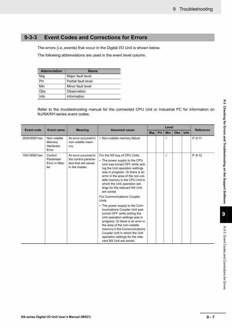
9 - 7
9 Troubleshooting
NX-series Digital I/O Unit User’s Manual (W521)
9-3 Checking for Errors and Troubleshooting on the Support Softw
are
9
9-3-3 Event C
odes and Corrections for E
rrors
The errors (i.e.,events) that occur in the Digital I/O Unit is shown below.
The following abbreviations are used in the event level column.
Refer to the troubleshooting manual for the connected CPU Unit or Industrial PC for information onNJ/NX/NY-series event codes.
9-3-3 Event Codes and Corrections for Errors
Abbreviation NameMaj Major fault levelPrt Partial fault levelMin Minor fault levelObs ObservationInfo Information
Event code Event name Meaning Assumed causeLevel
ReferenceMaj Prt Min Obs Info
00200000 hex Non-volatile Memory Hardware Error
An error occurred in non-volatile mem-ory.
• Non-volatile memory failure √ P. 9-11
10410000 hex Control Parameter Error in Mas-ter
An error occurred in the control parame-ters that are saved in the master.
For the NX bus of CPU Units• The power supply to the CPU
Unit was turned OFF while writ-ing the Unit operation settings was in progress. Or there is an error in the area of the non-vol-atile memory in the CPU Unit in which the Unit operation set-tings for the relevant NX Unit are saved.
For Communications Coupler Units• The power supply to the Com-
munications Coupler Unit was turned OFF while writing the Unit operation settings was in progress. Or there is an error in the area of the non-volatile memory in the Communications Coupler Unit in which the Unit operation settings for the rele-vant NX Unit are saved.
√ P. 9-12

9 Troubleshooting
9 - 8 NX-series Digital I/O Unit User’s Manual (W521)
80200000 hex NX Unit I/O Communica-tions Error
An I/O communica-tions error occurred in an NX Unit.
For the NX bus of CPU Units• An error that prevents normal
NX bus communications occurred in a CPU Unit.
• An NX Unit is not mounted properly.
• The power cable for the Unit power supply is disconnected, or the wiring from the Unit power supply to the NX Units is incorrect.
• The power cable for the Unit power supply is broken.
• The voltage of the Unit power supply is outside the specified range, or the capacity of the Unit power supply is insuffi-cient.
• There is a hardware error in an NX Unit.
For Communications Coupler Units• An error that prevents normal
NX bus communications occurred in a Communications Coupler Unit.
• The NX Unit is not mounted properly.
• The power cable for the Unit power supply is disconnected. Or, the wiring from the Unit power supply to the NX Units is incorrect.
• The power cable for the Unit power supply is broken.
• The voltage of the Unit power supply is outside the specified range. Or, the capacity of the Unit power supply is insuffi-cient.
• There is a hardware error in the NX Unit.
√ P. 9-13
80210000 hex NX Unit Out-put Synchro-nization Error
An output synchro-nization error occurred in the NX Unit.
For the NX bus of CPU Units• I/O refreshing on the NX bus is
not performed normally due to an error in the CPU Unit.
For Communications Coupler Units• The communications cable con-
nected to the Communications Coupler Unit is broken or the connection is faulty.
• The communications cable is affected by noise.
√ P. 9-15
Event code Event name Meaning Assumed causeLevel
ReferenceMaj Prt Min Obs Info

9 - 9
9 Troubleshooting
NX-series Digital I/O Unit User’s Manual (W521)
9-3 Checking for Errors and Troubleshooting on the Support Softw
are
9
9-3-3 Event C
odes and Corrections for E
rrors
80240000 hex NX Unit Clock Not Synchro-nized Error
A time information error occurred in an NX Unit.
For the NX bus of CPU Units• There is a hardware error in an
NX Unit.• There is a hardware error in a
CPU Unit.For Communications Coupler Units• There is a hardware error in an
NX Unit.• There is a hardware error in an
EtherCAT Coupler Unit.
√ P. 9-16
70010000 hex Previous Time Speci-fied
A previous time was specified for output refreshing with a specified time stamp.
For the NX bus of CPU Units• A past time is specified due to
an error in the user program.• A Task Period Exceeded error
occurred in a CPU Unit.For Communications Coupler Units• A past time is specified due to
an error in the user program.• A Task Period Exceeded error
occurred in a CPU Unit.• The arrival of I/O data at an NX
Unit was delayed due to a Communications Synchroniza-tion Error or other communica-tions error.
√ P. 9-17
90400000 hex Event Log Cleared
The event log was cleared.
• The event log was cleared by the user.
√ P. 9-18
Event code Event name Meaning Assumed causeLevel
ReferenceMaj Prt Min Obs Info

9 Troubleshooting
9 - 10 NX-series Digital I/O Unit User’s Manual (W521)
This section describes the information that is given for individual errors.
The items that are used to describe individual errors (events) are described in the following copy of an error table.
9-3-4 Meaning of Error
Error Descriptions
Event name Gives the name of the error. Event code Gives the code of the error.Meaning Gives a short description of the error.Source Gives the source of the error. Source
detailsGives details on the source of the error.
Detection timing
Tells when the error is detected.
Error attributes
Level Tells the level of influence on control.*1
*1. One of the following:Major fault: Major fault levelPartial fault: Partial fault levelMinor fault: Minor fault levelObservationInformation
Log category Tells which log the error is saved in.*2
*2. One of the following:System: System event logAccess: Access event log
Recovery Gives the recovery method.*3
*3. One of the following:Automatic recovery: Normal status is restored automatically when the cause of the error is removed.Error reset: Normal status is restored when the error is reset after the cause of the error is removed.Cycle the power supply: Normal status is restored when the power supply to the Controller is turned OFF and then back ON after the cause of the error is removed.Controller reset: Normal status is restored when the Controller is reset after the cause of the error is removed.Depends on cause: The recovery method depends on the cause of the error.
Effects User program Tells what will happen to exe-cution of the user program.*4
*4. One of the following:Continues: Execution of the user program will continue.Stops: Execution of the user program stops.Starts: Execution of the user program starts.
Operation Provides special information on the operation that results from the error.
Indicators Gives the status of the built-in EtherNet/IP port and built-in EtherCAT port indicators. Indicator status is given only for errors in the EtherCAT Master Function Module and the EtherNet/IP Function Module.
System-defined variables
Variable Data type NameLists the variable names, data types, and meanings for system-defined variables that provide direct error notification, that are directly affected by the error, or that contain settings that cause the error.
Cause and correction
Assumed cause Correction PreventionLists the possible causes, corrections, and preventive measures for the error.
Attached information
This is the attached information that is displayed by the Support Software or an HMI.*5,*6
*5. “System information” indicates internal system information that is used by OMRON.*6. Refer to the appendices of the troubleshooting manual for the connected CPU Unit or Industrial PC for the applicable
range of the HMI Troubleshooter.
Precautions/Remarks
Provides precautions, restrictions, and supplemental information. If the user can set the event level, the event lev-els that can be set, the recovery method, operational information, and other information are also provided.

9 - 11
9 Troubleshooting
NX-series Digital I/O Unit User’s Manual (W521)
9-3 Checking for Errors and Troubleshooting on the Support Softw
are
9
9-3-4 Meaning of E
rror
Event name Non-volatile Memory Hardware Error Event code 00200000 hexMeaning An error occurred in non-volatile memory.Source Depends on where the Support
Software is connected and the system configuration.
Source details NX Unit Detection timing
When power is turned ON to the NX Unit
Error attributes
Level Minor fault Log category SystemRecovery For the NX bus of CPU Units
Cycle the power supply to the Unit or restart the NX bus.
For Communications Coupler Units
Cycle the power supply to the Unit or restart the Slave Terminal.
If the errors are detected in the Controller, reset all of the errors in the Controller.Effects User program Continues. Operation I/O refreshing for the NX Unit stops. Messages can-
not be sent to the NX Unit.Sys-tem-defined variables
Variable Data type NameNone --- ---
Cause and correction
Assumed cause Correction PreventionNon-volatile memory failure. For the NX bus of CPU Units
Cycle the power supply to the Unit or restart the NX bus. If the error persists even after you make the above correction, replace the rele-vant NX Unit.
For Communications Coupler Units
Cycle the power supply to the Unit or restart the Slave Terminal. If the error persists even after you make the above correction, replace the relevant NX Unit.
None
Attached information
None
Precautions/Remarks
None

9 Troubleshooting
9 - 12 NX-series Digital I/O Unit User’s Manual (W521)
Event name Control Parameter Error in Master Event code 10410000 hexMeaning An error occurred in the control parameters that are saved in the master.Source Depends on where the Support
Software is connected and the system configuration.
Source details NX Unit Detection timing
When power is turned ON to the NX Unit
Error attributes
Level Minor fault Log category SystemRecovery For the NX bus of CPU Units
When Fail-soft Operation Is Set to Stop
Restart the NX Unit and then reset the error in the NX Bus Function Module.
When Fail-soft Operation Is Set to Fail-soft
Restart the NX Unit and then reset the error in the NX Unit.For Communications Coupler Units
When Fail-soft Operation Is Set to Stop
If the errors are detected in the Controller, restart the NX Unit and then reset all of the errors in the Controller.
If the errors are not detected in the Controller, restart the NX Unit and then reset the error in the Communications Coupler Unit.
When Fail-soft Operation Is Set to Fail-soft
Restart the NX Unit and then reset the error in the Communications Coupler Unit.
Effects User program Continues. Operation I/O refreshing for the NX Unit stops.Sys-tem-defined variables
Variable Data type NameNone --- ---
Cause and correction
Assumed cause Correction PreventionFor the NX bus of CPU UnitsThe power supply to the CPU Unit was turned OFF while writing the Unit operation settings was in progress. Or there is an error in the area of the non-volatile mem-ory in the CPU Unit in which the Unit operation settings for the rel-evant NX Unit are saved.
Download the Unit operation set-tings of the NX Unit again. If the error persists even after you make the above correction, replace the CPU Unit.
Do not turn OFF the power supply to the CPU Unit while transfer of the Unit operation settings for the NX Unit or save of NX Unit param-eters by a message is in progress.
For Communications Coupler UnitsThe power supply to the Commu-nications Coupler Unit was turned OFF while writing the Unit opera-tion settings was in progress. Or there is an error in the area of the non-volatile memory in the Com-munications Coupler Unit in which the Unit operation settings for the relevant NX Unit are saved.
Download the Unit operation set-tings of the NX Unit again. If the error occurs again even after you make the above correction, replace the Communications Cou-pler Unit.
Do not turn OFF the power supply to the Communications Coupler Unit while transfer of the Unit operation settings for the NX Unit by the Support Software or save of NX Unit parameters by a mes-sage is in progress.
Attached information
None
Precautions/Remarks
None
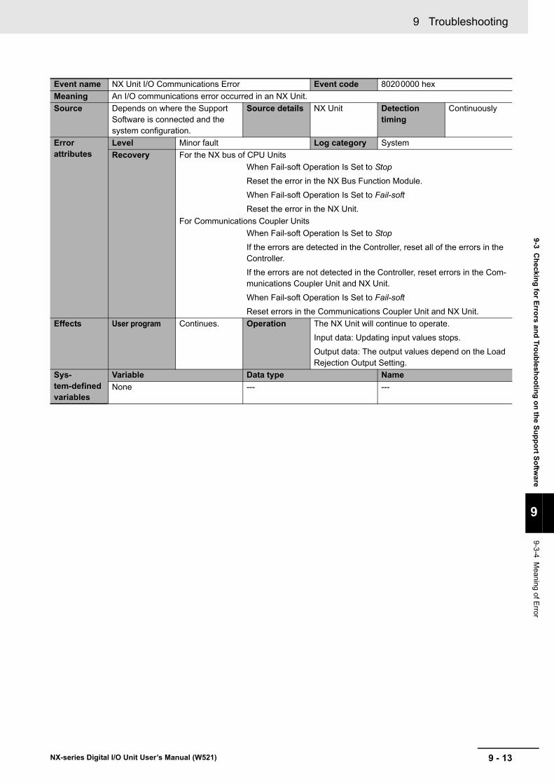
9 - 13
9 Troubleshooting
NX-series Digital I/O Unit User’s Manual (W521)
9-3 Checking for Errors and Troubleshooting on the Support Softw
are
9
9-3-4 Meaning of E
rror
Event name NX Unit I/O Communications Error Event code 80200000 hexMeaning An I/O communications error occurred in an NX Unit.Source Depends on where the Support
Software is connected and the system configuration.
Source details NX Unit Detection timing
Continuously
Error attributes
Level Minor fault Log category SystemRecovery For the NX bus of CPU Units
When Fail-soft Operation Is Set to Stop
Reset the error in the NX Bus Function Module.
When Fail-soft Operation Is Set to Fail-soft
Reset the error in the NX Unit.For Communications Coupler Units
When Fail-soft Operation Is Set to Stop
If the errors are detected in the Controller, reset all of the errors in the Controller.
If the errors are not detected in the Controller, reset errors in the Com-munications Coupler Unit and NX Unit.
When Fail-soft Operation Is Set to Fail-soft
Reset errors in the Communications Coupler Unit and NX Unit.Effects User program Continues. Operation The NX Unit will continue to operate.
Input data: Updating input values stops.
Output data: The output values depend on the Load Rejection Output Setting.
Sys-tem-defined variables
Variable Data type NameNone --- ---

9 Troubleshooting
9 - 14 NX-series Digital I/O Unit User’s Manual (W521)
Cause and correction
Assumed cause Correction PreventionFor the NX bus of CPU UnitsAn error that prevents normal NX bus communications occurred in a CPU Unit.
Check the error that occurred in the CPU Unit and perform the required corrections.
Take preventive measures against the error that occurred in the CPU Unit.
An NX Unit is not mounted prop-erly.
Mount the NX Units and End Cover securely and secure them with End Plates.
Mount the NX Units and End Cover securely and secure them with End Plates.
The power cable for the Unit power supply is disconnected, or the wiring from the Unit power supply to the NX Units is incorrect.
Wire the Unit power supply to the NX Units securely.
Wire the Unit power supply to the NX Units securely.
The power cable for the Unit power supply is broken.
If the power cable between the Unit power supply and the NX Units is broken, replace it.
None
The voltage of the Unit power sup-ply is outside the specified range, or the capacity of the Unit power supply is insufficient.
Configure the power supply sys-tem configuration correctly according to the power supply design method.
Configure the power supply sys-tem configuration correctly according to the power supply design method.
There is a hardware error in an NX Unit.
If the error persists even after you make the above correction, replace the NX Unit.
None
For Communications Coupler UnitsAn error that prevents normal NX bus communications occurred in a Communications Coupler Unit.
Check the error that occurred in the Communications Coupler Unit and perform the required correc-tions.
Take preventive measures against the error that occurred in the Com-munications Coupler Unit.
The NX Unit is not mounted prop-erly.
Mount the NX Units and End Cover securely and secure them with End Plates.
Mount the NX Units and End Cover securely and secure them with End Plates.
The power cable for the Unit power supply is disconnected. Or, the wiring from the Unit power supply to the NX Units is incorrect.
Correctly wire the Unit power sup-ply to the NX Units.
Correctly wire the Unit power sup-ply to the NX Units.
The power cable for the Unit power supply is broken.
If the power cable between the Unit power supply and the NX Units is broken, replace it.
None
The voltage of the Unit power sup-ply is outside the specified range.
Or, the capacity of the Unit power supply is insufficient.
Correctly configure the power sup-ply system according to the power supply design methods.
Correctly configure the power sup-ply system according to the power supply design methods.
There is a hardware error in the NX Unit.
If the error occurs again even after you make the above correction, replace the NX Unit.
None
Attached information
None
Precautions/Remarks
None

9 - 15
9 Troubleshooting
NX-series Digital I/O Unit User’s Manual (W521)
9-3 Checking for Errors and Troubleshooting on the Support Softw
are
9
9-3-4 Meaning of E
rror
Event name NX Unit Output Synchronization Error Event code 80210000 hexMeaning An output synchronization error occurred in the NX Unit.Source Depends on where the Support
Software is connected and the system configuration.
Source details NX Unit Detection timing
Continuously
Error attributes
Level Minor fault Log category SystemRecovery For the NX bus of CPU Units
Reset the error in the NX Bus Function Module.
For Communications Coupler Units
Reset all of the errors in the Controller.Effects User program Continues. Operation The NX Unit will continue to operate.
Input data: Updating input values stops.
Output data: The output values depend on the Load Rejection Output Setting.
Sys-tem-defined variables
Variable Data type NameNone --- ---
Cause and correction
Assumed cause Correction PreventionFor the NX bus of CPU Units I/O refreshing on the NX bus is not performed normally due to an error in the CPU Unit.
Check the error that occurred in the CPU Unit and perform the required corrections.
Take preventive measures against the error that occurred in the CPU Unit.
For Communications Coupler UnitsThe communications cable con-nected to the Communications Coupler Unit is broken or the con-nection is faulty.
Replace the communications cable or wire the cable correctly.
Wire the communications cable correctly.
The communications cable is affected by noise.
Set the Consecutive Communications Error Detection Count parameter for the Communications Coupler Unit to a suitable value that will not cause problems in operation.
Implement noise countermeasures if there is excessive noise.
Implement noise countermeasures. Refer to the operation manuals for the specific Units for noise countermeasures.
Attached information
None
Precautions/Remarks
None

9 Troubleshooting
9 - 16 NX-series Digital I/O Unit User’s Manual (W521)
Event name NX Unit Clock Not Synchronized Error Event code 80240000 hexMeaning A time information error occurred in an NX Unit.Source Depends on where the Support
Software is connected and the system configuration.
Source details NX Unit Detection timing
Continuously
Error attributes
Level Minor fault Log category SystemRecovery For the NX bus of CPU Units
Cycle the power supply to the Unit.
For Communications Coupler Units
Cycle the power supply to the Unit and then reset all of the errors in the Controller.Effects User program Continues. Operation The NX Unit will continue to operate.
Input data: Updating input values stops.
Output data: The output values depend on the Load Rejection Output Setting.
Sys-tem-defined variables
Variable Data type NameNone --- ---
Cause and correction
Assumed cause Correction PreventionFor the NX bus of CPU UnitsThere is a hardware error in an NX Unit.
If the error occurs only in a spe-cific NX Unit, replace the relevant NX Unit.
None
There is a hardware error in a CPU Unit.
If the error occurs in all of the NX Units mounted on a CPU Unit, replace the CPU Unit.
None
For Communications Coupler UnitsThere is a hardware error in an NX Unit.
If the error occurs only in a spe-cific NX Unit, replace the relevant NX Unit.
None
There is a hardware error in an EtherCAT Coupler Unit.
If the error occurs in all of the NX Units mounted on a Communica-tions Coupler Unit, replace the Communications Coupler Unit.
None
Attached information
None
Precautions/Remarks
None

9 - 17
9 Troubleshooting
NX-series Digital I/O Unit User’s Manual (W521)
9-3 Checking for Errors and Troubleshooting on the Support Softw
are
9
9-3-4 Meaning of E
rror
Event name Previous Time Specified Event code 70010000 hexMeaning A previous time was specified for output refreshing with a specified time stamp.Source Depends on where the Support
Software is connected and the system configuration.
Source details NX Unit Detection timing
Continuously
Error attributes
Level Observation Log category SystemRecovery Reset error in the NX Unit.
Effects User program Continues. Operation The output value that is specified for the previous time is not output.
Sys-tem-defined variables
Variable Data type NameNone --- ---
Cause and correction
Assumed cause Correction PreventionFor the NX bus of CPU UnitsA past time is specified due to an error in the user program.
Correct the user program so that it does not specify a past time.
Check in the user program to make sure that it does not specify a past time.
A Task Period Exceeded error occurred in a CPU Unit.
Perform the required corrections for the Task Period Exceeded error that occurred in the CPU Unit.
Take preventive measures against the Task Period Exceeded error that occurred in the CPU Unit.
For Communications Coupler UnitsA past time is specified due to an error in the user program.
Correct the user program so that it does not specify a past time. If the error persists even though the pro-gram does not specify a past time, change the specified time to a later time.
Check in the user program to make sure that it does not specify a past time. If the error persists even though the program does not specify a past time, change the specified time to a later time.
A Task Period Exceeded error occurred in a CPU Unit.
Perform the required corrections for the Task Period Exceeded error that occurred in the CPU Unit.
Take preventive measures against the Task Period Exceeded error that occurred in the CPU Unit.
The arrival of I/O data at an NX Unit was delayed due to a Com-munications Synchronization Error or other communications error.
Refer to the corrections for the Communications Synchronization Error that occurred in a Communi-cations Coupler Unit to prevent the error.
Take preventive measures against the Communications Synchroniza-tion Error that occurred in the Communications Coupler Unit.
Attached information
None
Precautions/Remarks
None

9 Troubleshooting
9 - 18 NX-series Digital I/O Unit User’s Manual (W521)
Event name Event Log Cleared Event code 90400000 hexMeaning The event log was cleared.Source Depends on where the Support
Software is connected and the system configuration.
Source details NX Unit Detection timing
When commanded from user
Error attributes
Level Information Log category Access
Recovery ---Effects User program Continues. Operation Not affected.Sys-tem-defined variables
Variable Data type NameNone --- ---
Cause and correction
Assumed cause Correction PreventionThe event log was cleared by the user.
--- ---
Attached information
Attached information: Events that were cleared
1: The system event log was cleared.
2: The access event log was cleared.Precautions/Remarks
None

9 - 19
9 Troubleshooting
NX-series Digital I/O Unit User’s Manual (W521)
9-4 Resetting Errors
9
9-4 Resetting Errors
Refer to the user’s manual for the connected CPU Unit or Communications Coupler for information on how to reset errors.

9 Troubleshooting
9 - 20 NX-series Digital I/O Unit User’s Manual (W521)
9-5 Troubles Specific To Each Type of NX Units
9-5-1 Digital Inputs
Problem Assumed cause CorrectionAlthough a connected external device is ON, nothing is input and the input indicator is not lit either.
The I/O power is not supplied. Check that the I/O power is supplied.The I/O power supply voltage is outside the rated range.
Set the I/O power supply voltage within the rated range.
The Unit is not wired correctly with the connected external device.
Check the wiring with the connected external device.
The wiring to the connected external device is discon-nected.
Check the wiring with the connected external device.
A connected external device is defective.
Replace the connected external device.
A connected external device is ON and the input indicator is lit, but nothing is input.
An NX bus error or a commu-nications error occurred.
When the Unit is connected to the CPU Unit, check if a NX bus error occurred.
In the case of a Slave Terminal, check if a NX bus or host communication error occurred.
There is a delay in the ON and OFF timing for input values.
An input filter may be set. Set the input filter value to 0. Alternatively, change the input filter to an appropriate value.

9 - 21
9 Troubleshooting
NX-series Digital I/O Unit User’s Manual (W521)
9-5 Troubles Specific To Each Type of NX U
nits
9
9-5-2 Digital O
utputs
9-5-2 Digital Outputs
Problem Assumed cause CorrectionWhen the output is ON, nothing is output although the output indicator is lit.
The I/O power is not supplied. Check that the I/O power is supplied.The I/O power supply voltage is outside the rated range.
Set the I/O power supply voltage within the rated range.
The Unit is not wired correctly with the connected external device.
Check the wiring with the connected external device.
The wiring to the connected external device is discon-nected.
Check the wiring with the connected external device.
A connected external device is defective.
Replace the connected external device.
Load short-circuit protection is in progress.
Refer to 7-4-3 Load Short-circuit Protection on page 7-17 and correct the problem.
Although the output is ON, nothing is output and the output indicator is not lit either.
A communications error occurred.
Check if a communications (NX bus) error occurred.
Cannot hold outputs when NX bus errors or commu-nications errors occur.
The load rejection output set-ting is set to "OFF".
Set the load rejection output setting to "Hold the present value".
Cannot clear outputs NX bus errors or when com-munications errors occur.
The load rejection output set-ting is set to "Hold the present value".
Set the load rejection output setting to "OFF".

9 Troubleshooting
9 - 22 NX-series Digital I/O Unit User’s Manual (W521)
9-6 Troubleshooting Flowchart
Refer to the user’s manual for the connected CPU Unit or Communications Coupler Unit for details on the standard troubleshooting process when an error occurs.
10 - 1
10
NX-series Digital I/O Unit User’s Manual (W521)
This section describes how to clean, inspect, and maintain the system.
10-1 Cleaning and Inspection . . . . . . . . . . . . . . . . . . . . . . . . . . . . . . . . . . . . . . . 10-210-1-1 Cleaning . . . . . . . . . . . . . . . . . . . . . . . . . . . . . . . . . . . . . . . . . . . . . . . . . . . . . 10-210-1-2 Periodic Inspection . . . . . . . . . . . . . . . . . . . . . . . . . . . . . . . . . . . . . . . . . . . . . 10-2
10-2 Maintenance Procedures . . . . . . . . . . . . . . . . . . . . . . . . . . . . . . . . . . . . . . . 10-5
Inspection and Maintenance
10 Inspection and Maintenance
10 - 2 NX-series Digital I/O Unit User’s Manual (W521)
10-1 Cleaning and Inspection
This section describes daily device maintenance such as cleaning and inspection.
Make sure to perform daily or periodic inspections in order to maintain the Digital I/O Unit's functions in the best operating condition.
Perform the following cleaning procedures periodically to ensure Digital I/O Units are maintained in the best operating condition.
• Wipe the equipment over with a soft, dry cloth when performing daily cleaning.• If dirt remains even after wiping with a soft, dry cloth, wipe with a cloth that has been wet with a suffi-
ciently diluted detergent (2%) and wrung dry.• Units will become stained if items such as rubber, vinyl products, or adhesive tape are left on the NX
Unit for a long period. Remove such items during regular cleaning.
Precautions for Correct Use
• Never use benzene, thinners, other volatile solvents, or chemical cloths.• Do not touch the NX bus connectors.
NX Units do not have parts with a specific life. However, its elements can deteriorate under improper environmental conditions. Periodic inspections are thus required to ensure that the required conditions are being maintained.
Inspection is recommended at least once every six months to a year, but more frequent inspections may be necessary depending on the severe environments.
Take immediate steps to correct the situation if any of the conditions in the following table are not met.
10-1-1 Cleaning
10-1-2 Periodic Inspection

10 - 3
10 Inspection and Maintenance
NX-series Digital I/O Unit User’s Manual (W521)
10-1 Cleaning and Inspection
10
10-1-2 Periodic Inspection
Periodic Inspection Items
No. Inspec-tion item Inspection details Criteria Correction
1 External power sup-ply
Is the power supply voltage mea-sured at the terminal block within standards?
Within the power supply voltage range
Use a voltage tester to check the power supply at the terminals. Take necessary steps to bring the power supply within the power supply voltage range.
2 I/O power supply
Is the power supply voltage mea-sured at the I/O terminal block within standards?
Voltages must be within I/O specifications of each NX Unit.
Use a voltage tester to check the power voltage at the terminals. Take necessary steps to bring the I/O power supply within NX Unit standards.
3 Ambient environ-ment
Is the ambient operating tem-perature within standards?
0 to 55°C Use a thermometer to check the tem-perature and ensure that the ambient operating temperature remains within the allowed range of 0 to 55°C.
Is the ambient operating humid-ity within standards?
Relative humidity must be 10% to 95% with no con-densation.
Use a hygrometer to check the humidity and ensure that the ambient operating humidity remains between 10% and 95%.Make sure that condensation does not occur due to rapid changes in tempera-ture.
Is it subject to direct sunlight? Not in direct sunlight Protect the Controller if necessary.Is there an accumulation of dirt, dust, salt, metal powder, etc.?
No accumulation Clean and protect the Controller if neces-sary.
Is there water, oil, or chemical sprays hitting the Controller?
No spray Clean and protect the Controller if neces-sary.
Are there corrosive or flammable gases in the area of the Control-ler?
No spray Check by smell or use a sensor.
Is the Unit subject to shock or vibration?
Vibration resistance and shock resistance must be within specifications.
Install cushioning or other vibration and shock absorbing equipment if necessary.
Are there noise sources near the Controller?
No significant noise sources
Either separate the Controller and noise source, or protect the Controller.
4 Installation and wiring
Are the DIN track mounting hooks for each NX Unit securely locked?
No looseness Securely lock the DIN track mounting hooks.
Are the cable connectors fully inserted and locked?
No looseness Correct any improperly installed connec-tors.
Are there any loose screws on the End Plates (PFP-M)?
No looseness Tighten loose screws with a Phillips-head screwdriver.
Are the NX Units connected to each other along the hookup guides and inserted until they touch the DIN track?
You must connect and fix the NX Units to the DIN track.
Connect the NX Units to each other along the hookup guides and insert them until they touch the DIN track.
Are there any damaged external wiring cables?
No visible damage Check visually and replace cables if nec-essary.

10 Inspection and Maintenance
10 - 4 NX-series Digital I/O Unit User’s Manual (W521)
Required Tools• Phillips screwdriver• Flat-blade screwdriver• Voltage tester or digital voltmeter• Industrial alcohol and pure cotton cloth
Tools Required Occasionally• Oscilloscope• Thermometer and hygrometer
Tools Required for Inspections

10 - 5
10 Inspection and Maintenance
NX-series Digital I/O Unit User’s Manual (W521)
10-2 Maintenance Procedures
10
10-2 Maintenance Procedures
When you replace a Digital I/O Unit, follow the procedure in the user’s manual for the connected CPU Unit or Communications Coupler Unit.

10 Inspection and Maintenance
10 - 6 NX-series Digital I/O Unit User’s Manual (W521)

A - 1
A
NX-series Digital I/O Unit User’s Manual (W521)
This section describes the data sheets of the Digital I/O Units and their dimensions.
A-1 Data Sheet . . . . . . . . . . . . . . . . . . . . . . . . . . . . . . . . . . . . . . . . . . . . . . . . . . . . A-2A-1-1 Model List . . . . . . . . . . . . . . . . . . . . . . . . . . . . . . . . . . . . . . . . . . . . . . . . . . . . . A-2A-1-2 Digital Input Units . . . . . . . . . . . . . . . . . . . . . . . . . . . . . . . . . . . . . . . . . . . . . . . A-7A-1-3 Digital Output Units . . . . . . . . . . . . . . . . . . . . . . . . . . . . . . . . . . . . . . . . . . . . . A-38A-1-4 Digital Mixed I/O Units . . . . . . . . . . . . . . . . . . . . . . . . . . . . . . . . . . . . . . . . . . A-82
A-2 Dimensions . . . . . . . . . . . . . . . . . . . . . . . . . . . . . . . . . . . . . . . . . . . . . . . . . . A-96A-2-1 Screwless Clamping Terminal Block Type . . . . . . . . . . . . . . . . . . . . . . . . . . . A-96A-2-2 M3 Screw Terminal Block Type . . . . . . . . . . . . . . . . . . . . . . . . . . . . . . . . . . . . A-98A-2-3 Connector Types . . . . . . . . . . . . . . . . . . . . . . . . . . . . . . . . . . . . . . . . . . . . . . . A-99
A-3 Connecting Connector-Terminal Block Conversion Units and I/O Relay Terminals . . . . . . . . . . . . . . . . . . . . . . . . . . . . . . . . . . . . . . . A-102A-3-1 Patterns for Combining Connector-Terminal Block Conversion Units
and I/O Relay Terminals . . . . . . . . . . . . . . . . . . . . . . . . . . . . . . . . . . . . . . . . A-102A-3-2 Combinations of Connections . . . . . . . . . . . . . . . . . . . . . . . . . . . . . . . . . . . . A-104A-3-3 Connector-Terminal Block Conversion Unit Connection Diagrams . . . . . . . . A-110A-3-4 Connection Diagrams for I/O Relay Terminals . . . . . . . . . . . . . . . . . . . . . . . A-127
A-4 EMC Directive Measures for Relay Outputs . . . . . . . . . . . . . . . . . . . . . . A-133A-5 List of NX Objects . . . . . . . . . . . . . . . . . . . . . . . . . . . . . . . . . . . . . . . . . . . A-134
A-5-1 Format of Object Descriptions . . . . . . . . . . . . . . . . . . . . . . . . . . . . . . . . . . . A-134A-5-2 Digital Input Units . . . . . . . . . . . . . . . . . . . . . . . . . . . . . . . . . . . . . . . . . . . . . A-135A-5-3 Digital Output Units . . . . . . . . . . . . . . . . . . . . . . . . . . . . . . . . . . . . . . . . . . . . A-143A-5-4 Digital Mixed I/O Units . . . . . . . . . . . . . . . . . . . . . . . . . . . . . . . . . . . . . . . . . A-152
A-6 List of Screwless Clamping Terminal Block Models . . . . . . . . . . . . . . . A-157A-6-1 Model Notation . . . . . . . . . . . . . . . . . . . . . . . . . . . . . . . . . . . . . . . . . . . . . . . A-157A-6-2 List of Terminal Block Models . . . . . . . . . . . . . . . . . . . . . . . . . . . . . . . . . . . . A-157
A-7 Version Information with CPU Units . . . . . . . . . . . . . . . . . . . . . . . . . . . . . A-158A-7-1 Relationship between Unit Versions of Units . . . . . . . . . . . . . . . . . . . . . . . . A-158
A-8 Version Information with Communications Coupler Units . . . . . . . . . . . A-160A-8-1 Connection to an EtherCAT Coupler Unit . . . . . . . . . . . . . . . . . . . . . . . . . . . A-160A-8-2 Connection to an EtherNet/IP Coupler Unit . . . . . . . . . . . . . . . . . . . . . . . . . A-162
A-9 Displaying the Edit Unit Operation Settings Tab Page . . . . . . . . . . . . . . A-164A-9-1 Connection to the CPU Unit . . . . . . . . . . . . . . . . . . . . . . . . . . . . . . . . . . . . . A-164A-9-2 Slave Terminal . . . . . . . . . . . . . . . . . . . . . . . . . . . . . . . . . . . . . . . . . . . . . . . A-166
Appendices

Appendices
A - 2 NX-series Digital I/O Unit User’s Manual (W521)
A-1 Data Sheet
The specifications of individual Digital I/O Unit are shown below.
A-1-1 Model List
DC Input Units (Screwless Clamping Terminal Block, 12 mm Width)
Model
Number of
points
Internal I/O common
Rated input voltage I/O refreshing method ON/OFF response
time Reference
NX-ID3317
4 points
NPN
12 to 24 VDC Switching Synchro-nous I/O refreshing and Free-Run refresh-ing
20 μs max./400 μs max. P. A-9
NX-ID3343
24 VDC 100 ns max./100 ns max.
P. A-11
NX-ID3344Input refreshing with input changed time only
P. A-13
NX-ID3417
PNP
12 to 24 VDC Switching Synchro-nous I/O refreshing and Free-Run refresh-ing
20 μs max./400 μs max. P. A-14
NX-ID3443
24 VDC
100 ns max./100 ns max.
P. A-16
NX-ID3444Input refreshing with input changed time only
P. A-17
NX-ID4342 8 points
NPNSwitching Synchro-nous I/O refreshing and Free-Run refresh-ing
20 μs max./400 μs max.
P. A-18
NX-ID4442 PNP P. A-20
NX-ID5342 16 points
NPN P. A-22
NX-ID5442 PNP P. A-24
DC Input Units (M3 Screw Terminal Block, 30 mm Width)
Model
Number of
points
Internal I/O common
Rated input voltage I/O refreshing method ON/OFF response
time Reference
NX-ID5142-116 points
For both NPN/PNP 24 VDC
Switching Synchro-nous I/O refreshing and Free-Run refresh-ing
20 μs max./400 μs max. P. A-26

A - 3
Appendices
NX-series Digital I/O Unit User’s Manual (W521)
A-1 D
ata Sheet
A
A-1-1 M
odel List
DC Input Units (MIL Connector, 30 mm Width)
Model
Number of
points
Internal I/O common
Rated input voltage I/O refreshing method ON/OFF response
time Reference
NX-ID5142-516 points
For both NPN/PNP 24 VDC
Switching Synchro-nous I/O refreshing and Free-Run refreshing
20 μs max./400 μs max.
P. A-28
NX-ID6142-532 points
For both NPN/PNP 24 VDC P. A-30
DC Input Units (Fujitsu Connector, 30 mm Width)
Model
Number of
points
Internal I/O common
Rated input voltage I/O refreshing method ON/OFF response
time Reference
NX-ID6142-632 points
For both NPN/PNP 24 VDC
Switching Synchro-nous I/O refreshing and Free-Run refresh-ing
20 μs max./400 μs max. P. A-33
AC Input Units (Screwless Clamping Terminal Block, 12 mm Width)
Model
Number of
points
Rated input voltage I/O refreshing method ON/OFF response time Reference
NX-IA31174 points
200 to 240 VAC, 50/60 Hz (170 to 264 VAC, ±3 Hz) Free-Run refreshing 10 ms max./40 ms
max. P. A-36

Appendices
A - 4 NX-series Digital I/O Unit User’s Manual (W521)
Transistor Output Units (Screwless Clamping Terminal Block, 12 mm Width)
Model
Number of
points
Internal I/O common
Maximum value of load
current
Rated volt-age
I/O refresh-ing method
ON/OFF response
timeReference
NX-OD2154 2 points
NPN0.5 A/point, 1 A/Unit 24 VDC
Output refreshing with specified time stamp only
300 ns max./300 ns max.
P. A-40
NX-OD2258 PNP P. A-42
NX-OD3121
4 points
NPN
0.5 A/point, 2 A/Unit
12 to 24 VDC
Switching Syn-chronous I/O refreshing and Free-Run refreshing
0.1 ms max./0.8 ms max.
P. A-44
NX-OD3153
24 VDC
300 ns max./300 ns max.
P. A-46
NX-OD3256
PNP
0.5 ms max./1.0 ms max.
P. A-48
NX-OD3257300 ns max./300 ns max.
P. A-50
NX-OD3268 2 A/point, 8 A/Unit
0.5 ms max./1.0 ms max.
P. A-52
NX-OD41218 points
NPN
0.5 A/point, 4 A/Unit
12 to 24 VDC0.1 ms max./0.8 ms max.
P. A-54
NX-OD4256 PNP 24 VDC0.5 ms max./1.0 ms max.
P. A-56
NX-OD512116 points
NPN 12 to 24 VDC0.1 ms max./0.8 ms max.
P. A-58
NX-OD5256 PNP 24 VDC0.5 ms max./1.0 ms max.
P. A-60
Transistor Output Units (M3 Screw Terminal Block, 30 mm Width)
Model
Number of
points
Internal I/O common
Maximum value of load
current
Rated volt-age
I/O refresh-ing method
ON/OFF response
timeReference
NX-OD5121-116 points
NPN0.5 A/point, 5 A/Unit
12 to 24 VDC Switching Syn-chronous I/O refreshing and Free-Run refreshing
0.1 ms max./0.8 ms max.
P. A-62
NX-OD5256-1 PNP 24 VDC0.5 ms max./1.0 ms max.
P. A-64

A - 5
Appendices
NX-series Digital I/O Unit User’s Manual (W521)
A-1 D
ata Sheet
A
A-1-1 M
odel List
Transistor Output Units (MIL Connector, 30 mm Width)
Model Number of points
Internal I/O common
Maximum value of load
current
Rated volt-age
I/O refresh-ing method
ON/OFF response
time
Refer-ence
NX-OD5121-5
16 points
NPN0.5 A/point, 2 A/Unit
12 to 24 VDC
Switching Syn-chronous I/O refreshing and Free-Run refreshing
0.1 ms max./0.8 ms max.
P. A-66
NX-OD5256-5 PNP 24 VDC0.5 ms max./1.0 ms max.
P. A-68
NX-OD6121-5
32 points
NPN0.5 A/point, 2 A/common, 4 A/Unit
12 to 24 VDC0.1 ms max./0.8 ms max.
P. A-70
NX-OD6256-5 PNP 24 VDC0.5 ms max./1.0 ms max.
P. A-72
Transistor Output Units (Fujitsu Connector, 30 mm Width)
Model Number of points
Internal I/O common
Maximum value of load
current
Rated volt-age
I/O refresh-ing method
ON/OFF response
time
Refer-ence
NX-OD6121-6 32 points NPN0.5 A/point, 2 A/common, 4 A/Unit
12 to 24 VDC
Switching Syn-chronous I/O refreshing and Free-Run refreshing
0.1 ms max./0.8 ms max.
P. A-74
Relay Output Units (Screwless Clamping Terminal Block, 12 mm Width)
Model
Number of
points
Relay type Maximum switching capacity I/O refresh-ing method
ON/OFF response
timeReference
NX-OC2633 2 points
N.O. 250 VAC/2 A (cosΦ = 1), 250 VAC/2 A (cosΦ = 0.4), 24 VDC/2 A, 4 A/Unit
Free-Run refreshing
15 ms max./15 ms max.
P. A-76
NX-OC2733 N.O. + N.C. P. A-78

Appendices
A - 6 NX-series Digital I/O Unit User’s Manual (W521)
Relay Output Units (Screwless Clamping Terminal Block, 24 mm Width)
Model
Number of
points
Relay type Maximum switching capacity I/O refresh-ing method
ON/OFF response
timeReference
NX-OC46338 points
N.O.
250 VAC/2A(cosφ=1),250 VAC/2A(cosφ=0.4),24 VDC/2A,8 A/Unit
Free-Runrefreshing
15 msmax./15 msmax.
P. A-80
DC Input/Transistor Output Units (MIL Connector, 30 mm Width)
Model Number of points
Internal I/O common
Maximum value of load
current
Rated volt-age
I/O refresh-ing method
ON/OFF response
time
Refer-ence
NX-MD6121-5
Outputs: 16 pointsInputs: 16 points
Outputs: NPNInputs: For both NPN/PNP
0.5 A/point, 2 A/Unit
Outputs: 12 to 24 VDCInputs: 24 VDC Switching Syn-
chronous I/O refreshing and Free-Run refreshing
Outputs: 0.1 ms max./0.8 ms max.Inputs: 20 μs max./400 μs max.
P. A-84
NX-MD6256-5
Outputs: PNPInputs: For both NPN/PNP
Outputs: 24 VDCInputs: 24 VDC
Outputs: 0.5 ms max./1.0 ms max.Inputs: 20 μs max./400 μs max.
P. A-88
DC Input/Transistor Output Units (Fujitsu Connector, 30 mm Width)
Model Number of points
Internal I/O common
Maximum value of load
current
Rated volt-age
I/O refresh-ing method
ON/OFF response
time
Refer-ence
NX-MD6121-6
Outputs: 16 pointsInputs: 16 points
Outputs: NPNInputs: For both NPN/PNP
0.5 A/point, 2 A/Unit
Outputs: 12 to 24 VDCInputs: 24 VDC
Switching Syn-chronous I/O refreshing and Free-Run refreshing
Outputs: 0.1 ms max./0.8 ms max.Inputs: 20 μs max./400 μs max.
P. A-92

A - 7
Appendices
NX-series Digital I/O Unit User’s Manual (W521)
A-1 D
ata Sheet
A
A-1-2 D
igital Input Units
The meanings of the items on the data sheet of the DC Input Unit are explained in the table below.
A-1-2 Digital Input Units
Description of Items on Data Sheet of the DC Input Units
Item DescriptionUnit name The name of the Unit.Model The model of the Unit.Number of points The number of input points provided by the Unit.External connection terminals
The type of terminal block and connector that is used for connecting the Unit. The number of termi-nals on the terminal block is also described when a screwless clamping terminal block is used.
I/O refreshing method The I/O refreshing methods that are used by the Unit. Free-Run refreshing, synchronous I/O refreshing and input refreshing with input changed time are available.
Indicators The type of indicators on the Unit and the layout of those indicators.Internal I/O common The polarity of the input devices that are connected to the Unit. NPN connection and PNP connec-
tion are available.Rated input voltage The rated input voltage and range of the Unit.Input current The input current at the rated voltage of the Unit.ON voltage/ON current The input voltage in which the Unit input turns ON, and corresponding input current.OFF voltage/OFF cur-rent
The input voltage in which the Unit input turns OFF, and corresponding input current.
ON/OFF response time
The delay time for which the status change of the input terminals reaches the internal circuit of the Unit. The input filter time below is not included. It is described according to the ON/OFF sequence.
Input filter time The filter time when the status of the internal circuit is read as the data to the internal of the Unit. It is same for both ON/OFF. The filter time to be set by the Support Software is described.
Dimensions The dimensions of the Unit. They are described as W x H x D. The unit is "mm".Isolation method The isolation method between the input circuit and internal circuit of the Unit.Insulation resistance The insulation resistance between the input circuit and internal circuit of the Unit.Dielectric strength The dielectric strength between the input circuit and internal circuit of the Unit.I/O power supply method
The method for supplying I/O power to the Unit. The supply method is determined for each Unit. The power is supplied from the NX bus or the external source.
Current capacity of I/O power supply terminal
The current capacity of the power supply terminals (IOV/IOG) of the Unit. Do not exceed this value when supplying the I/O power to the connected external devices.
NX Unit power con-sumption
The power consumption of the NX Unit power supply of the Unit. The power consumption when NX Units are connected to a CPU Unit and the power consumption when NX Units are connected to a Communications Coupler Unit.
Current consumption from I/O power supply
The current consumption from I/O power supply of the Unit. The above input current and current consumption of any connected external devices are excluded.
Weight The weight of the Unit.Circuit layout The input circuit layout of the Unit.Installation orienta-tion and restrictions
The installation orientation of a CPU Unit containing the Unit and the installation orientation of a Slave Terminal containing the Unit. Any restrictions to specifications that result from the installation orientation are also given.
Terminal connection diagram
A diagram of the connection between the Unit and connected external devices. When an I/O Power Supply Connection Unit or a Shield Connection Unit is required to be connected to the con-nected external devices, the description for such is included.
Disconnec-tion/Short-circuit detection
The function of the Unit to detect a disconnection/short-circuit.
Protective function The protective function that the Unit has.

Appendices
A - 8 NX-series Digital I/O Unit User’s Manual (W521)
The meanings of the items on the data sheet of the AC Input Units are explained in the table below.
Description of Items on Data Sheet of the AC Input Units
Item DescriptionUnit name The name of the Unit.Model The model of the Unit.Number of points The number of input points provided by the Unit.External connection terminals
The type of terminal block and connector that is used for connecting the Unit. The number of termi-nals on the terminal block is also described when a screwless clamping terminal block is used.
I/O refreshing method The I/O refreshing methods that are used by the Unit. Free-Run refreshing, synchronous I/O refreshing and input refreshing with input changed time are available.
Indicators The type of indicators on the Unit and the layout of those indicators.Internal I/O common The polarity of the input devices that are connected to the Unit. NPN connection and PNP connec-
tion are available.Rated input voltage The rated input voltage and range of the Unit.Input current The input current at the rated voltage of the Unit.ON voltage/ON current The input voltage in which the Unit input turns ON, and corresponding input current.OFF voltage/OFF cur-rent
The input voltage in which the Unit input turns OFF, and corresponding input current.
ON/OFF response time
The delay time for which the status change of the input terminals reaches the internal circuit of the Unit. The input filter time below is not included. It is described according to the ON/OFF sequence.
Input filter time The filter time when the status of the internal circuit is read as the data to the internal of the Unit. It is same for both ON/OFF. The filter time to be set by the Support Software is described.
Dimensions The dimensions of the Unit. They are described as W x H x D. The unit is "mm".Isolation method The isolation method between the input circuit and internal circuit of the Unit.Insulation resistance The insulation resistance between the input circuit and internal circuit of the Unit.Dielectric strength The dielectric strength between the input circuit and internal circuit of the Unit.I/O power supply method
The method for supplying I/O power to the Unit. The supply method is determined for each Unit. The power is supplied from the NX bus or the external source.
Current capacity of I/O power supply terminal
The current capacity of the power supply terminals of the Unit. Do not exceed this value when supplying the I/O power to the connected external devices.
NX Unit power con-sumption
The power consumption of the NX Unit power supply of the Unit. The power consumption when NX Units are connected to a CPU Unit and the power consumption when NX Units are connected to a Communications Coupler Unit.
Current consumption from I/O power supply
The current consumption from I/O power supply of the Unit. The above input current and current consumption of any connected external devices are excluded.
Weight The weight of the Unit.Circuit layout The input circuit layout of the Unit.Installation orienta-tion and restrictions
The installation orientation of a CPU Unit containing the Unit and the installation orientation of a Slave Terminal containing the Unit. Any restrictions to specifications that result from the installation orientation are also given.
Terminal connection diagram
A diagram of the connection between the Unit and connected external devices. When an I/O Power Supply Connection Unit or a Shield Connection Unit is required to be connected to the con-nected external devices, the description for such is included.
Disconnec-tion/Short-circuit detection
The function of the Unit to detect a disconnection/short-circuit.
Protective function The protective function that the Unit has.

A - 9
Appendices
NX-series Digital I/O Unit User’s Manual (W521)
A-1 D
ata Sheet
A
A-1-2 D
igital Input Units
DC Input Units (Screwless Clamping Terminal Block, 12 mm Width)
Unit name DC Input Unit Model NX-ID3317Number of points 4 points External connection
terminalsScrewless clamping terminal block (12 ter-minals)
I/O refreshing method Switching Synchronous I/O refreshing and Free-Run refreshingIndicators TS indicator, input indicators Internal I/O common NPN
Rated input voltage 12 to 24 VDC (9 to 28.8 VDC)Input current 6 mA typical (at 24 VDC), rated currentON voltage/ON current 9 VDC min./3 mA min. (between IOV and
each signal)OFF voltage/OFF cur-rent
2 VDC max./1 mA max. (between IOV and each signal)
ON/OFF response time 20 μs max./400 μs max.Input filter time No filter, 0.25 ms, 0.5 ms, 1 ms (default), 2
ms, 4 ms, 8 ms, 16 ms, 32 ms, 64 ms, 128 ms, 256 ms
Dimensions 12 (W) x 100 (H) x 71 (D) Isolation method Photocoupler isolationInsulation resistance 20 MΩ min. between isolated circuits (at
100 VDC)Dielectric strength 510 VAC between isolated circuits for 1
minute at a leakage current of 5 mA max.I/O power supply method
Supply from the NX bus Current capacity of I/O power supply terminal
IOV: 0.1 A/terminal max., IOG: 0.1 A/termi-nal max.
NX Unit power con-sumption
• Connected to a CPU Unit0.90 W max.
• Connected to a Communications Cou-pler Unit0.50 W max.
Current consumption from I/O power supply
No consumption
Weight 65 g max.Circuit layout
Installation orienta-tion and restrictions
Installation orientation:• Connected to a CPU Unit
Possible in upright installation.• Connected to a Communications Coupler Unit
Possible in 6 orientations.
Restrictions: No restrictions
IOV0 to 3
IN0 to IN3
IOG0 to 3
NX bus connector (left)
Terminal block
I/O power supply +
I/O power supply −
Inte
rnal
circ
uits
I/O power supply +
I/O power supply −
NX bus connector (right)
Current controlcircuit

Appendices
A - 10 NX-series Digital I/O Unit User’s Manual (W521)
Terminal connection diagram
Disconnec-tion/Short-circuit detection
Not supported. Protective function Not supported.
Additional I/O Power Supply Unit
DC Input UnitNX-ID3317
Two-wire sensor
12 to 24 VDC
Three-wiresensor
IOV
IOG
IOV
IOG
IOV
IOG
IOV
IOG
IN0
IOG0
IOV2
IOV0
A1 B1
A8 B8
IN2
IOG2
IN1
IOG1
IOV3
IOV1
IN3
IOG3
A1 B1
A8 B8

A - 11
Appendices
NX-series Digital I/O Unit User’s Manual (W521)
A-1 D
ata Sheet
A
A-1-2 D
igital Input Units
Unit name DC Input Unit Model NX-ID3343Number of points 4 points External connection
terminalsScrewless clamping terminal block (12 ter-minals)
I/O refreshing method Switching Synchronous I/O refreshing and Free-Run refreshingIndicators TS indicator, input indicators Internal I/O common NPN
Rated input voltage 24 VDC (15 to 28.8 VDC)Input current 3.5 mA typical (at 24 VDC), rated currentON voltage/ON current 15 VDC min./3 mA min. (between IOV and
each signal)OFF voltage/OFF cur-rent
5 VDC max./1 mA max. (between IOV and each signal)
ON/OFF response time 100 ns max./100 ns max.Input filter time No filter, 1 μs, 2 μs, 4 μs, 8 μs (default), 16
μs, 32 μs, 64 μs, 128 μs, 256 μsDimensions 12 (W) x 100 (H) x 71 (D) Isolation method Digital isolator isolationInsulation resistance 20 MΩ min. between isolated circuits (at
100 VDC)Dielectric strength 510 VAC between isolated circuits for 1
minute at a leakage current of 5 mA max.I/O power supply method
Supply from the NX bus Current capacity of I/O power supply terminal
IOV: 0.1 A/terminal max., IOG: 0.1 A/termi-nal max.
NX Unit power con-sumption
• Connected to a CPU Unit0.90 W max.
• Connected to a Communications Cou-pler Unit0.55 W max.
Current consumption from I/O power supply
30 mA max.
Weight 65 g max.Circuit layout
Installation orienta-tion and restrictions
Installation orientation:• Connected to a CPU Unit
Possible in upright installation.• Connected to a Communications Coupler Unit
Possible in 6 orientations.
Restrictions: No restrictionsTerminal connection diagram
IOV0 to 3
IN0 to IN3
IOG0 to 3
NX bus connector (left)
Terminal block
I/O power supply +
I/O power supply −
Inte
rnal
circ
uits
Isol
atio
n cir
cuit
I/O power supply +
I/O power supply −
NX bus connector (right)
Current controlcircuit
Powersupply
Two-wire sensor
Three-wiresensor
24 VDC
Additional I/O Power Supply Unit
DC Input UnitNX-ID3343
IOV
IOG
IOV
IOG
IOV
IOG
IOV
IOG
IN0
IOG0
IOV2
IOV0
A1 B1
A8 B8
IN2
IOG3
IN1
IOG1
IOV3
IOV1
IN3
IOG3
A1 B1
A8 B8

Appendices
A - 12 NX-series Digital I/O Unit User’s Manual (W521)
Disconnec-tion/Short-circuit detection
Not supported. Protective function Not supported.
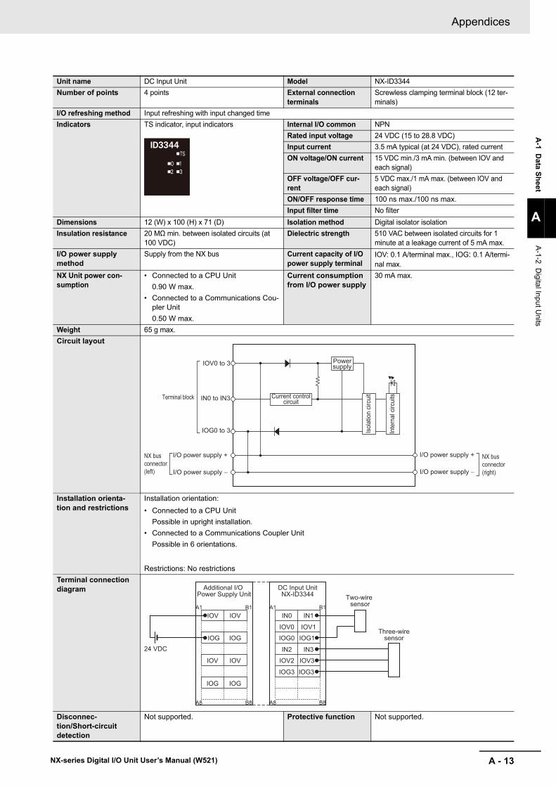
A - 13
Appendices
NX-series Digital I/O Unit User’s Manual (W521)
A-1 D
ata Sheet
A
A-1-2 D
igital Input Units
Unit name DC Input Unit Model NX-ID3344Number of points 4 points External connection
terminalsScrewless clamping terminal block (12 ter-minals)
I/O refreshing method Input refreshing with input changed timeIndicators TS indicator, input indicators Internal I/O common NPN
Rated input voltage 24 VDC (15 to 28.8 VDC)Input current 3.5 mA typical (at 24 VDC), rated currentON voltage/ON current 15 VDC min./3 mA min. (between IOV and
each signal)OFF voltage/OFF cur-rent
5 VDC max./1 mA max. (between IOV and each signal)
ON/OFF response time 100 ns max./100 ns max.Input filter time No filter
Dimensions 12 (W) x 100 (H) x 71 (D) Isolation method Digital isolator isolationInsulation resistance 20 MΩ min. between isolated circuits (at
100 VDC)Dielectric strength 510 VAC between isolated circuits for 1
minute at a leakage current of 5 mA max.I/O power supply method
Supply from the NX bus Current capacity of I/O power supply terminal
IOV: 0.1 A/terminal max., IOG: 0.1 A/termi-nal max.
NX Unit power con-sumption
• Connected to a CPU Unit0.90 W max.
• Connected to a Communications Cou-pler Unit0.50 W max.
Current consumption from I/O power supply
30 mA max.
Weight 65 g max.Circuit layout
Installation orienta-tion and restrictions
Installation orientation:• Connected to a CPU Unit
Possible in upright installation.• Connected to a Communications Coupler Unit
Possible in 6 orientations.
Restrictions: No restrictionsTerminal connection diagram
Disconnec-tion/Short-circuit detection
Not supported. Protective function Not supported.
IOV0 to 3
IN0 to IN3
IOG0 to 3
Terminal blockIn
tern
al c
ircui
ts
Isol
atio
n cir
cuitCurrent control
circuit
Powersupply
NX bus connector (left)
I/O power supply +
I/O power supply −
I/O power supply +
I/O power supply −
NX bus connector (right)
Two-wire sensor
Three-wiresensor
24 VDC
Additional I/O Power Supply Unit
DC Input UnitNX-ID3344
IOV
IOG
IOV
IOG
IOV
IOG
IOV
IOG
IN0
IOG0
IOV2
IOV0
A1 B1
A8 B8
IN2
IOG3
IN1
IOG1
IOV3
IOV1
IN3
IOG3
A1 B1
A8 B8

Appendices
A - 14 NX-series Digital I/O Unit User’s Manual (W521)
Unit name DC Input Unit Model NX-ID3417Number of points 4 points External connection
terminalsScrewless clamping terminal block (12 ter-minals)
I/O refreshing method Switching Synchronous I/O refreshing and Free-Run refreshingIndicators TS indicator, input indicators Internal I/O common PNP
Rated input voltage 12 to 24 VDC (9 to 28.8 VDC)Input current 6 mA typical (at 24 VDC), rated currentON voltage/ON current 9 VDC min./3 mA min. (between IOG and
each signal)OFF voltage/OFF cur-rent
2 VDC max./1 mA max. (between IOG and each signal)
ON/OFF response time 20 μs max./400 μs max.Input filter time No filter, 0.25 ms, 0.5 ms, 1 ms (default), 2
ms, 4 ms, 8 ms, 16 ms, 32 ms, 64 ms, 128 ms, 256 ms
Dimensions 12 (W) x 100 (H) x 71 (D) Isolation method Photocoupler isolationInsulation resistance 20 MΩ min. between isolated circuits (at
100 VDC)Dielectric strength 510 VAC between isolated circuits for 1
minute at a leakage current of 5 mA max.I/O power supply method
Supply from the NX bus Current capacity of I/O power supply terminal
IOV: 0.1 A/terminal max., IOG: 0.1 A/termi-nal max.
NX Unit power con-sumption
• Connected to a CPU Unit0.90 W max.
• Connected to a Communications Cou-pler Unit0.50 W max.
Current consumption from I/O power supply
No consumption
Weight 65 g max.Circuit layout
Installation orienta-tion and restrictions
Installation orientation:• Connected to a CPU Unit
Possible in upright installation.• Connected to a Communications Coupler Unit
Possible in 6 orientations.
Restrictions: No restrictionsTerminal connection diagram
IOV0 to 3
IN0 to IN3
IOG0 to 3
Terminal block
Inte
rnal
circ
uitsCurrent control
circuit
NX bus connector (left)
I/O power supply +
I/O power supply −
I/O power supply +
I/O power supply −
NX bus connector (right)
Two-wire sensor
Three-wire sensor
12 to 24 VDC
DC Input UnitNX-ID3417
Additional I/O Power Supply Unit
IOV
IOG
IOV
IOG
IOV
IOG
IOV
IOG
IN0
IOG0
IOV2
IOV0
A1 B1
A8 B8
IN2
IOG2
IN1
IOG1
IOV3
IOV1
IN3
IOG3
A1 B1
A8 B8

A - 15
Appendices
NX-series Digital I/O Unit User’s Manual (W521)
A-1 D
ata Sheet
A
A-1-2 D
igital Input Units
Disconnec-tion/Short-circuit detection
Not supported. Protective function Not supported.

Appendices
A - 16 NX-series Digital I/O Unit User’s Manual (W521)
Unit name DC Input Unit Model NX-ID3443Number of points 4 points External connection
terminalsScrewless clamping terminal block (12 ter-minals)
I/O refreshing method Switching Synchronous I/O refreshing and Free-Run refreshingIndicators TS indicator, input indicators Internal I/O common PNP
Rated input voltage 24 VDC (15 to 28.8 VDC)Input current 3.5 mA typical (at 24 VDC), rated currentON voltage/ON current 15 VDC min./3 mA min. (between IOG and
each signal)OFF voltage/OFF cur-rent
5 VDC max./1 mA max. (between IOG and each signal)
ON/OFF response time 100 ns max./100 ns max.Input filter time No filter, 1 μs, 2 μs, 4 μs, 8 μs (default), 16
μs, 32 μs, 64 μs, 128 μs, 256 μsDimensions 12 (W) x 100 (H) x 71 (D) Isolation method Digital isolator isolationInsulation resistance 20 MΩ min. between isolated circuits (at
100 VDC)Dielectric strength 510 VAC between isolated circuits for 1
minute at a leakage current of 5 mA max.I/O power supply method
Supply from the NX bus Current capacity of I/O power supply terminal
IOV: 0.1 A/terminal max., IOG: 0.1 A/termi-nal max.
NX Unit power con-sumption
• Connected to a CPU Unit0.90 W max.
• Connected to a Communications Cou-pler Unit0.55 W max.
Current consumption from I/O power supply
30 mA max.
Weight 65 g max.Circuit layout
Installation orienta-tion and restrictions
Installation orientation:• Connected to a CPU Unit
Possible in upright installation.• Connected to a Communications Coupler Unit
Possible in 6 orientations.
Restrictions: No restrictionsTerminal connection diagram
Disconnec-tion/Short-circuit detection
Not supported. Protective function Not supported.
IOV0 to 3
IN0 to IN3
IOG0 to 3
Terminal blockIn
tern
al c
ircui
ts
Isol
atio
n cir
cuitCurrent control
circuit
Powersupply
NX bus connector (left)
I/O power supply +
I/O power supply −
I/O power supply +
I/O power supply −
NX bus connector (right)
Two-wire sensor
Three-wire sensor
24 VDC
DC Input UnitNX-ID3443
Additional I/O Power Supply Unit
IOV
IOG
IOV
IOG
IOV
IOG
IOV
IOG
IN0
IOG0
IOV2
IOV0
A1 B1
A8 B8
IN2
IOG2
IN1
IOG1
IOV3
IOV1
IN3
IOG3
A1 B1
A8 B8

A - 17
Appendices
NX-series Digital I/O Unit User’s Manual (W521)
A-1 D
ata Sheet
A
A-1-2 D
igital Input Units
Unit name DC Input Unit Model NX-ID3444Number of points 4 points External connection
terminalsScrewless clamping terminal block (12 ter-minals)
I/O refreshing method Input refreshing with input changed timeIndicators TS indicator, input indicators Internal I/O common PNP
Rated input voltage 24 VDC (15 to 28.8 VDC)Input current 3.5 mA typical (at 24 VDC), rated currentON voltage/ON current 15 VDC min./3 mA min. (between IOG and
each signal)OFF voltage/OFF cur-rent
5 VDC max./1 mA max. (between IOG and each signal)
ON/OFF response time 100 ns max./100 ns max.Input filter time No filter
Dimensions 12 (W) x 100 (H) x 71 (D) Isolation method Digital isolator isolationInsulation resistance 20 MΩ min. between isolated circuits (at
100 VDC)Dielectric strength 510 VAC between isolated circuits for 1
minute at a leakage current of 5 mA max.I/O power supply method
Supply from the NX bus Current capacity of I/O power supply terminal
IOV: 0.1 A/terminal max., IOG: 0.1 A/termi-nal max.
NX Unit power con-sumption
• Connected to a CPU Unit0.90 W max.
• Connected to a Communications Cou-pler Unit0.50 W max.
Current consumption from I/O power supply
30 mA max.
Weight 65 g max.Circuit layout
Installation orienta-tion and restrictions
Installation orientation:• Connected to a CPU Unit
Possible in upright installation.• Connected to a Communications Coupler Unit
Possible in 6 orientations.
Restrictions: No restrictionsTerminal connection diagram
Disconnec-tion/Short-circuit detection
Not supported. Protective function Not supported.
IOV0 to 3
IN0 to IN3
IOG0 to 3
Terminal blockIn
tern
al c
ircui
ts
Isol
atio
n cir
cuitCurrent control
circuit
Powersupply
NX bus connector (left)
I/O power supply +
I/O power supply −
I/O power supply +
I/O power supply −
NX bus connector (right)
Two-wire sensor
Three-wire sensor
24 VDC
DC Input UnitNX-ID3444
Additional I/O Power Supply Unit
IOV
IOG
IOV
IOG
IOV
IOG
IOV
IOG
IN0
IOG0
IOV2
IOV0
A1 B1
A8 B8
IN2
IOG2
IN1
IOG1
IOV3
IOV1
IN3
IOG3
A1 B1
A8 B8
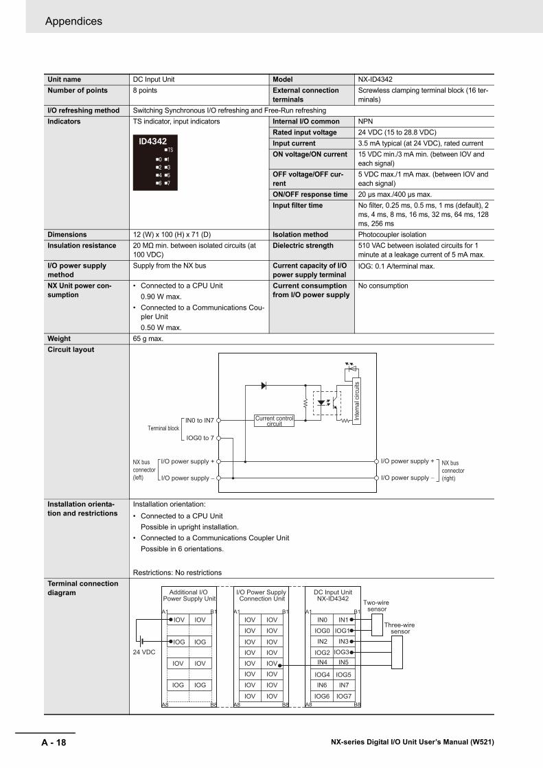
Appendices
A - 18 NX-series Digital I/O Unit User’s Manual (W521)
Unit name DC Input Unit Model NX-ID4342Number of points 8 points External connection
terminalsScrewless clamping terminal block (16 ter-minals)
I/O refreshing method Switching Synchronous I/O refreshing and Free-Run refreshingIndicators TS indicator, input indicators Internal I/O common NPN
Rated input voltage 24 VDC (15 to 28.8 VDC)Input current 3.5 mA typical (at 24 VDC), rated currentON voltage/ON current 15 VDC min./3 mA min. (between IOV and
each signal)OFF voltage/OFF cur-rent
5 VDC max./1 mA max. (between IOV and each signal)
ON/OFF response time 20 μs max./400 μs max.Input filter time No filter, 0.25 ms, 0.5 ms, 1 ms (default), 2
ms, 4 ms, 8 ms, 16 ms, 32 ms, 64 ms, 128 ms, 256 ms
Dimensions 12 (W) x 100 (H) x 71 (D) Isolation method Photocoupler isolationInsulation resistance 20 MΩ min. between isolated circuits (at
100 VDC)Dielectric strength 510 VAC between isolated circuits for 1
minute at a leakage current of 5 mA max.I/O power supply method
Supply from the NX bus Current capacity of I/O power supply terminal
IOG: 0.1 A/terminal max.
NX Unit power con-sumption
• Connected to a CPU Unit0.90 W max.
• Connected to a Communications Cou-pler Unit0.50 W max.
Current consumption from I/O power supply
No consumption
Weight 65 g max.Circuit layout
Installation orienta-tion and restrictions
Installation orientation:• Connected to a CPU Unit
Possible in upright installation.• Connected to a Communications Coupler Unit
Possible in 6 orientations.
Restrictions: No restrictionsTerminal connection diagram
IN0 to IN7
IOG0 to 7Terminal block
Inte
rnal
circ
uits
Current controlcircuit
NX bus connector (left)
I/O power supply +
I/O power supply −
I/O power supply +
I/O power supply −
NX bus connector (right)
Two-wire sensor
Three-wire sensor
24 VDC
DC Input UnitNX-ID4342
Additional I/O Power Supply Unit
I/O Power Supply Connection Unit
IOV
IOV
IOV
IOV
IOV
IOV
IOV
IOV
IOV
IOV
IOV
IOV
IOV
IOV
IOV
IOV
IN0
IN2
IN4
IOG0
A1 B1
A8 B8
IOG2
IOG4
IN1
IN3
IN5
IOG1
IOG3
IOG6
IN6
IOG7
IN7IOG5
IOV
IOG
IOV
IOG
IOV
IOG
IOV
IOG
A1 B1
A8 B8
A1 B1
A8 B8

A - 19
Appendices
NX-series Digital I/O Unit User’s Manual (W521)
A-1 D
ata Sheet
A
A-1-2 D
igital Input Units
Disconnec-tion/Short-circuit detection
Not supported. Protective function Not supported.

Appendices
A - 20 NX-series Digital I/O Unit User’s Manual (W521)
Unit name DC Input Unit Model NX-ID4442Number of points 8 points External connection
terminalsScrewless clamping terminal block (16 ter-minals)
I/O refreshing method Switching Synchronous I/O refreshing and Free-Run refreshingIndicators TS indicator, input indicators Internal I/O common PNP
Rated input voltage 24 VDC (15 to 28.8 VDC)Input current 3.5 mA typical (at 24 VDC), rated currentON voltage/ON current 15 VDC min./3 mA min. (between IOG and
each signal)OFF voltage/OFF cur-rent
5 VDC max./1 mA max. (between IOG and each signal)
ON/OFF response time 20 μs max./400 μs max.Input filter time No filter, 0.25 ms, 0.5 ms, 1 ms (default), 2
ms, 4 ms, 8 ms, 16 ms, 32 ms, 64 ms, 128 ms, 256 ms
Dimensions 12 (W) x 100 (H) x 71 (D) Isolation method Photocoupler isolationInsulation resistance 20 MΩ min. between isolated circuits (at
100 VDC)Dielectric strength 510 VAC between isolated circuits for 1
minute at a leakage current of 5 mA max.I/O power supply method
Supply from the NX bus Current capacity of I/O power supply terminal
IOV: 0.1 A/terminal max.
NX Unit power con-sumption
• Connected to a CPU Unit0.90 W max.
• Connected to a Communications Cou-pler Unit0.50 W max.
Current consumption from I/O power supply
No consumption
Weight 65 g max.Circuit layout
Installation orienta-tion and restrictions
Installation orientation:• Connected to a CPU Unit
Possible in upright installation.• Connected to a Communications Coupler Unit
Possible in 6 orientations.
Restrictions: No restrictionsTerminal connection diagram
IN0 to IN7
IOV0 to 7Terminal block
Inte
rnal
circ
uits
Current controlcircuit
NX bus connector (left)
I/O power supply +
I/O power supply −
I/O power supply +
I/O power supply −
NX bus connector (right)
Two-wire sensor
Three-wiresensor
24 VDC
DC Input UnitNX-ID4442
Additional I/O Power Supply Unit
I/O Power Supply Connection Unit
IOG
IOG
IOG
IOG
IOG
IOG
IOG
IOG
IOG
IOG
IOG
IOG
IOG
IOG
IOG
IOG
IN0
IN2
IN4
IOV0
A1 B1
A8 B8
IOV2
IOV4
IN1
IN3
IN5
IOV1
IOV3
IOV6
IN6
IOV7
IN7
IOV5
IOV
IOG
IOV
IOG
IOV
IOG
IOV
IOG
A1 B1
A8 B8
A1 B1
A8 B8

A - 21
Appendices
NX-series Digital I/O Unit User’s Manual (W521)
A-1 D
ata Sheet
A
A-1-2 D
igital Input Units
Disconnec-tion/Short-circuit detection
Not supported. Protective function Not supported.

Appendices
A - 22 NX-series Digital I/O Unit User’s Manual (W521)
Unit name DC Input Unit Model NX-ID5342Number of points 16 points External connection
terminalsScrewless clamping terminal block (16 ter-minals)
I/O refreshing method Switching Synchronous I/O refreshing and Free-Run refreshingIndicators TS indicator, input indicators Internal I/O common NPN
Rated input voltage 24 VDC (15 to 28.8 VDC)Input current 2.5 mA typical (at 24 VDC), rated currentON voltage/ON current 15 VDC min./2 mA min. (between IOV and
each signal)OFF voltage/OFF cur-rent
5 VDC max./0.5 mA max. (between IOV and each signal)
ON/OFF response time 20 μs max./400 μs max.Input filter time No filter, 0.25 ms, 0.5 ms, 1 ms (default), 2
ms, 4 ms, 8 ms, 16 ms, 32 ms, 64 ms, 128 ms, 256 ms
Dimensions 12 (W) x 100 (H) x 71 (D) Isolation method Photocoupler isolationInsulation resistance 20 MΩ min. between isolated circuits (at
100 VDC)Dielectric strength 510 VAC between isolated circuits for 1
minute at a leakage current of 5 mA max.I/O power supply method
Supply from the NX bus Current capacity of I/O power supply terminal
Without I/O power supply terminals
NX Unit power con-sumption
• Connected to a CPU Unit0.90 W max.
• Connected to a Communications Cou-pler Unit0.55 W max.
Current consumption from I/O power supply
No consumption
Weight 65 g max.Circuit layout
Installation orienta-tion and restrictions
Installation orientation:• Connected to a CPU Unit
Possible in upright installation.• Connected to a Communications Coupler Unit
Possible in 6 orientations.
Restrictions: No restrictionsTerminal connection diagram
IN0 to IN15Terminal block Inte
rnal
circ
uits
Current controlcircuit
NX bus connector (left)
I/O power supply +
I/O power supply −
I/O power supply +
I/O power supply −
NX bus connector (right)
Two-wire sensor
Three-wire sensor24 VDC
DC Input UnitNX-ID5342
Additional I/O Power Supply Unit
I/O Power Supply Connection Unit
I/O Power Supply Connection Unit
IOG
IOG
IOG
IOG
IOG
IOG
IOG
IOG
IOG
IOG
IOG
IOG
IOG
IOG
IOG
IOG
IOV
IOV
IOV
IOV
IOV
IOV
IOV
IOV
IOV
IOV
IOV
IOV
IOV
IOV
IOV
IOV
IN0
IN4
IN8
IN2
A1 B1
A8 B8
IN6
IN10
IN1
IN5
IN9
IN3
IN7
IN14
IN12
IN15
IN13
IN11
IOV
IOG
IOV
IOG
IOV
IOG
IOV
IOG
A1 B1
A8 B8
A1 B1
A8 B8
A1 B1
A8 B8

A - 23
Appendices
NX-series Digital I/O Unit User’s Manual (W521)
A-1 D
ata Sheet
A
A-1-2 D
igital Input Units
Disconnec-tion/Short-circuit detection
Not supported. Protective function Not supported.

Appendices
A - 24 NX-series Digital I/O Unit User’s Manual (W521)
Unit name DC Input Unit Model NX-ID5442Number of points 16 points External connection
terminalsScrewless clamping terminal block (16 ter-minals)
I/O refreshing method Switching Synchronous I/O refreshing and Free-Run refreshingIndicators TS indicator, input indicators Internal I/O common PNP
Rated input voltage 24 VDC (15 to 28.8 VDC)Input current 2.5 mA typical (at 24 VDC), rated currentON voltage/ON current 15 VDC min./2 mA min. (between IOG and
each signal)OFF voltage/OFF cur-rent
5 VDC max./0.5 mA max. (between IOG and each signal)
ON/OFF response time 20 μs max./400 μs max.Input filter time No filter, 0.25 ms, 0.5 ms, 1 ms (default), 2
ms, 4 ms, 8 ms, 16 ms, 32 ms, 64 ms, 128 ms, 256 ms
Dimensions 12 (W) x 100 (H) x 71 (D) Isolation method Photocoupler isolationInsulation resistance 20 MΩ min. between isolated circuits (at
100 VDC)Dielectric strength 510 VAC between isolated circuits for 1
minute at a leakage current of 5 mA max.I/O power supply method
Supply from the NX bus Current capacity of I/O power supply terminal
Without I/O power supply terminals
NX Unit power con-sumption
• Connected to a CPU Unit0.90 W max.
• Connected to a Communications Cou-pler Unit0.55 W max.
Current consumption from I/O power supply
No consumption
Weight 65 g max.Circuit layout
Installation orienta-tion and restrictions
Installation orientation:• Connected to a CPU Unit
Possible in upright installation.• Connected to a Communications Coupler Unit
Possible in 6 orientations.
Restrictions: No restrictionsTerminal connection diagram
IN0 to IN15Terminal block
Inte
rnal
circ
uitsCurrent control
circuit
NX bus connector (left)
I/O power supply +
I/O power supply −
I/O power supply +
I/O power supply −
NX bus connector (right)
Two-wire sensor
Three-wire sensor24 VDC
DC Input UnitNX-ID5442
Additional I/O Power Supply Unit
I/O Power Supply Connection Unit
I/O Power Supply Connection Unit
IOG
IOG
IOG
IOG
IOG
IOG
IOG
IOG
IOG
IOG
IOG
IOG
IOG
IOG
IOG
IOG
IOV
IOV
IOV
IOV
IOV
IOV
IOV
IOV
IOV
IOV
IOV
IOV
IOV
IOV
IOV
IOV
IN0
IN4
IN8
IN2
A1 B1
A8 B8
IN6
IN10
IN1
IN5
IN9
IN3
IN7
IN14
IN12
IN15
IN13
IN11
IOV
IOG
IOV
IOG
IOV
IOG
IOV
IOG
A1 B1
A8 B8
A1 B1
A8 B8
A1 B1
A8 B8

A - 25
Appendices
NX-series Digital I/O Unit User’s Manual (W521)
A-1 D
ata Sheet
A
A-1-2 D
igital Input Units
Disconnec-tion/Short-circuit detection
Not supported. Protective function Not supported.

Appendices
A - 26 NX-series Digital I/O Unit User’s Manual (W521)
DC Input Units (M3 Screw Terminal Block, 30 mm Width)
Unit name DC Input Unit Model NX-ID5142-1Number of points 16 points External connection
terminalsM3 screw terminal block (18 terminals)
I/O refreshing method Switching Synchronous I/O refreshing and Free-Run refreshingIndicators TS indicator, input indicators Internal I/O common For both NPN/PNP
Rated input voltage 24 VDC (15 to 28.8 VDC)Input current 7 mA typical (at 24 VDC)ON voltage/ON current 15 VDC min./3 mA min. (between COM and
each signal)OFF voltage/OFF cur-rent
5 VDC max./1 mA max. (between COM and each signal)
ON/OFF response time 20 μs max./400 μs max.Input filter time No filter, 0.25 ms, 0.5 ms, 1 ms (default), 2
ms, 4 ms, 8 ms, 16 ms, 32 ms, 64 ms, 128 ms, 256 ms
Dimensions 30 (W) x 100 (H) x 71 (D) Isolation method Photocoupler isolationInsulation resistance 20 MΩ min. between isolated circuits (at
100 VDC)Dielectric strength 510 VAC between isolated circuits for 1
minute at a leakage current of 5 mA max.I/O power supply method
Supply from external source Current capacity of I/O power supply terminal
Without I/O power supply terminals
NX Unit power con-sumption
• Connected to a CPU Unit0.85 W max.
• Connected to a Communications Cou-pler Unit0.55 W max.
Current consumption from I/O power supply
No consumption
Weight 125 g max.Circuit layout
IN0to
IN15
COMCOM
Inte
rnal
circ
uits
Terminal block
Input indicator
3.3 kΩ
I/O power supply +NX bus
connector (left)
NX bus connector (right)I/O power
supply −
I/O power supply +I/O power supply −

A - 27
Appendices
NX-series Digital I/O Unit User’s Manual (W521)
A-1 D
ata Sheet
A
A-1-2 D
igital Input Units
Installation orienta-tion and restrictions
Installation orientation:• Connected to a CPU Unit
Possible in upright installation.• Connected to a Communications Coupler Unit
Possible in 6 orientations.
Restrictions: As shown in the following.
Terminal connection diagram
Disconnec-tion/Short-circuit detection
Not supported. Protective function Not supported.
06050403020100 5545
6050403020100
16
8
4
0
12
5545
16
8
4
12
Number of simultaneously ON input points vs. Ambient temperature characteristic
Number of simultaneously ON input points vs. Ambient temperature characteristic
16 points at 45°C
16 points at 45°C
12 points at 55°C
16 points at 40°C
7 points at 55°C
12 points at 55°C
Ambient temperature
Ambient temperature
• For upright installation
• For any installation other than upright
28.8 VI/O power supply voltage
Num
ber o
f sim
ulta
neou
sly
ON
inpu
t poi
nts
Num
ber o
f sim
ulta
neou
sly
ON
inpu
t poi
nts
I/O power supply voltage24 V28.8 V
(°C)
(°C)
A0A B
A2
A4
A1
A3
A5
A7A8
A6
B0
B2
B4
B1
B3
B5
B7B8
B6
IN2
IN6
IN0
IN4
IN8
IN12IN14COM
IN10
TerminalSignal Name Signal Name
24 VDC
IN3
IN7
IN1
IN5
IN9
IN13IN15COM
IN11
• The polarity of the input power supply can be connected in either direction.• Terminal numbers in the terminal connection diagram are used in this
manual, but they are not printed on all Units.
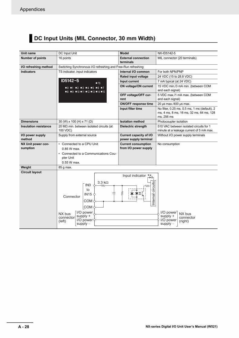
Appendices
A - 28 NX-series Digital I/O Unit User’s Manual (W521)
DC Input Units (MIL Connector, 30 mm Width)
Unit name DC Input Unit Model NX-ID5142-5Number of points 16 points External connection
terminalsMIL connector (20 terminals)
I/O refreshing method Switching Synchronous I/O refreshing and Free-Run refreshingIndicators TS indicator, input indicators Internal I/O common For both NPN/PNP
Rated input voltage 24 VDC (15 to 28.8 VDC)Input current 7 mA typical (at 24 VDC)ON voltage/ON current 15 VDC min./3 mA min. (between COM
and each signal)OFF voltage/OFF cur-rent
5 VDC max./1 mA max. (between COM and each signal)
ON/OFF response time 20 μs max./400 μs max.Input filter time No filter, 0.25 ms, 0.5 ms, 1 ms (default), 2
ms, 4 ms, 8 ms, 16 ms, 32 ms, 64 ms, 128 ms, 256 ms
Dimensions 30 (W) x 100 (H) x 71 (D) Isolation method Photocoupler isolationInsulation resistance 20 MΩ min. between isolated circuits (at
100 VDC)Dielectric strength 510 VAC between isolated circuits for 1
minute at a leakage current of 5 mA max.I/O power supply method
Supply from external source Current capacity of I/O power supply terminal
Without I/O power supply terminals
NX Unit power con-sumption
• Connected to a CPU Unit0.85 W max.
• Connected to a Communications Cou-pler Unit0.55 W max.
Current consumption from I/O power supply
No consumption
Weight 85 g max.Circuit layout
IN0to
IN15
COMCOM
Inte
rnal
circ
uits
Connector
Input indicator
3.3 kΩ
I/O power supply +NX bus
connector (left)
NX bus connector (right)I/O power
supply −
I/O power supply +I/O power supply −

A - 29
Appendices
NX-series Digital I/O Unit User’s Manual (W521)
A-1 D
ata Sheet
A
A-1-2 D
igital Input Units
Installation orienta-tion and restrictions
Installation orientation:• Connected to a CPU Unit
Possible in upright installation.• Connected to a Communications Coupler Unit
Possible in 6 orientations.
Restrictions: As shown in the following.
Terminal connection diagram
Disconnec-tion/Short-circuit detection
Not supported. Protective function Not supported.
06050403020100 5545
6050403020100
16
8
4
0
12
5545
16
8
4
12
Number of simultaneously ON input points vs. Ambient temperature characteristic
Number of simultaneously ON input points vs. Ambient temperature characteristic
16 points at 45°C
16 points at 45°C
12 points at 55°C
16 points at 40°C
7 points at 55°C
12 points at 55°C
Ambient temperature
Ambient temperature
• For upright installation
• For any installation other than upright
28.8 VI/O power supply voltage
Num
ber o
f sim
ulta
neou
sly
ON
inpu
t poi
nts
Num
ber o
f sim
ulta
neou
sly
ON
inpu
t poi
nts
I/O power supply voltage24 V28.8 V
(°C)
(°C)
1
5
9
3
7
11
151719
13
NC
IN15
IN13
COM
IN14
IN12
IN10IN09IN08
IN11
2
6
10
4
8
12
161820
14
Connector pin
Signal name
Signal name24 VDC
NC
IN07
IN05
COM
IN06
IN04
IN02IN01IN00
IN03
• The polarity of the input power supply can be connected in either direction.• Be sure to wire both pins 3 and 4 (COM), and set the same polarity for both pins.

Appendices
A - 30 NX-series Digital I/O Unit User’s Manual (W521)
Unit name DC Input Unit Model NX-ID6142-5Number of points 32 points External connection
terminalsMIL connector (40 terminals)
I/O refreshing method Switching Synchronous I/O refreshing and Free-Run refreshingIndicators TS indicator, input indicators Internal I/O common For both NPN/PNP
Rated input voltage 24 VDC (19 to 28.8 VDC)Input current 4.1 mA typical (24 VDC)ON voltage/ON current 19 VDC min./3 mA min. (between COM
and each signal)OFF voltage/OFF cur-rent
5 VDC max./1 mA max. (between COM and each signal)
ON/OFF response time 20 μs max./400 μs max.Input filter time No filter, 0.25 ms, 0.5 ms, 1 ms (default), 2
ms, 4 ms, 8 ms, 16 ms, 32 ms, 64 ms, 128 ms, 256 ms
Dimensions 30 (W) x 100 (H) x 71 (D) Isolation method Photocoupler isolationInsulation resistance 20 MΩ min. between isolated circuits (at
100 VDC)Dielectric strength 510 VAC between isolated circuits for 1
minute at a leakage current of 5 mA max.I/O power supply method
Supply from external source Current capacity of I/O power supply terminal
Without I/O power supply terminals
NX Unit power con-sumption
• Connected to a CPU Unit0.90 W max.
• Connected to a Communications Cou-pler Unit0.60 W max.
Current consumption from I/O power supply
No consumption
Weight 90 g max.Circuit layout
IN0to
IN15COM0COM0
COM1COM1
Input indicator3.3 kΩ
3.3 kΩConnector
I/O power supply +NX bus
connector (left)
I/O power supply −
IN16to
IN31
NX bus connector (right)
I/O power supply +I/O power supply −
Inte
rnal
circ
uits

A - 31
Appendices
NX-series Digital I/O Unit User’s Manual (W521)
A-1 D
ata Sheet
A
A-1-2 D
igital Input Units
Installation orienta-tion and restrictions
Installation orientation:• Connected to a CPU Unit
Possible in upright installation.• Connected to a Communications Coupler Unit
Possible in 6 orientations.
Restrictions: As shown in the following.
0
30
20
10
5
15
6050403020100 5545
25
35
6050403020100 5545
I/O power supply voltage24 V28.8 V
I/O power supply voltage
24 V28.8 V
19 V
32 points at 40°C
32 points at 35°C
32 points at 30°C
13 points/common at 55°C
13 points/common at 55°C
8 points/common at 55°C
5 points/common at 55°C
10 points/common at 55°C20
10
5
0
15
35
25
30
• For upright installation
• For any installation other than upright
Number of simultaneously ON input points vs. Ambient temperature characteristic
Number of simultaneously ON input points vs. Ambient temperature characteristic
Num
ber o
f sim
ulta
neou
sly
ON
inpu
t poi
nts
Num
ber o
f sim
ulta
neou
sly
ON
inpu
t poi
nts
32 points at 45°C
Ambient temperature
Ambient temperature
32 points at 50°C
(°C)
(°C)

Appendices
A - 32 NX-series Digital I/O Unit User’s Manual (W521)
Terminal connection diagram
Disconnec-tion/Short-circuit detection
Not supported. Protective function Not supported.
1
5
9
3
7
11
151719
13
NC
IN31
IN29
COM1
IN30
IN28
IN26IN25IN24
IN27
2
6
10
4
8
12
161820
14
21
25
29
23
27
31
353739
33
22
26
30
24
28
32
363840
34
24 VDC
24 VDC
NC
IN23
IN21
COM1
IN22
IN20
IN18IN17IN16
IN19
NC
IN15
IN13
COM0
IN14
IN12
IN10IN09IN08
IN11
NC
IN07
IN05
COM0
IN06
IN04
IN02IN01IN00
IN03
Connectorpin
Signalname
Signalname
• The polarity of the input power supply can be connected in either direction.• Be sure to wire both pins 23 and 24 (COM0), and set the same polarity for both pins.• Be sure to wire both pins 3 and 4 (COM1), and set the same polarity for both pins.
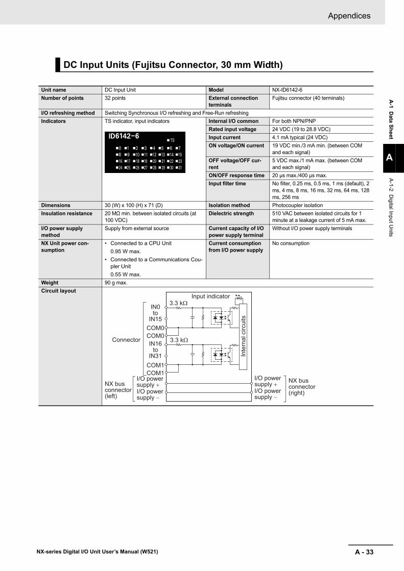
A - 33
Appendices
NX-series Digital I/O Unit User’s Manual (W521)
A-1 D
ata Sheet
A
A-1-2 D
igital Input Units
DC Input Units (Fujitsu Connector, 30 mm Width)
Unit name DC Input Unit Model NX-ID6142-6Number of points 32 points External connection
terminalsFujitsu connector (40 terminals)
I/O refreshing method Switching Synchronous I/O refreshing and Free-Run refreshingIndicators TS indicator, input indicators Internal I/O common For both NPN/PNP
Rated input voltage 24 VDC (19 to 28.8 VDC)Input current 4.1 mA typical (24 VDC)ON voltage/ON current 19 VDC min./3 mA min. (between COM
and each signal)OFF voltage/OFF cur-rent
5 VDC max./1 mA max. (between COM and each signal)
ON/OFF response time 20 μs max./400 μs max.Input filter time No filter, 0.25 ms, 0.5 ms, 1 ms (default), 2
ms, 4 ms, 8 ms, 16 ms, 32 ms, 64 ms, 128 ms, 256 ms
Dimensions 30 (W) x 100 (H) x 71 (D) Isolation method Photocoupler isolationInsulation resistance 20 MΩ min. between isolated circuits (at
100 VDC)Dielectric strength 510 VAC between isolated circuits for 1
minute at a leakage current of 5 mA max.I/O power supply method
Supply from external source Current capacity of I/O power supply terminal
Without I/O power supply terminals
NX Unit power con-sumption
• Connected to a CPU Unit0.95 W max.
• Connected to a Communications Cou-pler Unit0.55 W max.
Current consumption from I/O power supply
No consumption
Weight 90 g max.Circuit layout
IN0to
IN15COM0COM0
COM1COM1
Input indicator3.3 kΩ
3.3 kΩConnector
I/O power supply +NX bus
connector (left)
I/O power supply −
IN16to
IN31
NX bus connector (right)
I/O power supply +I/O power supply −
Inte
rnal
circ
uits

Appendices
A - 34 NX-series Digital I/O Unit User’s Manual (W521)
Installation orienta-tion and restrictions
Installation orientation:• Connected to a CPU Unit
Possible in upright installation.• Connected to a Communications Coupler Unit
Possible in 6 orientations.
Restrictions: As shown in the following.
0
30
20
10
5
15
6050403020100 5545
25
35
6050403020100 5545
I/O power supply voltage24 V28.8 V
I/O power supply voltage
24 V28.8 V
19 V
32 points at 40°C
32 points at 35°C
32 points at 30°C
13 points/common at 55°C
13 points/common at 55°C
8 points/common at 55°C
5 points/common at 55°C
10 points/common at 55°C20
10
5
0
15
35
25
30
• For upright installation
• For any installation other than upright
Number of simultaneously ON input points vs. Ambient temperature characteristic
Number of simultaneously ON input points vs. Ambient temperature characteristic
Num
ber o
f sim
ulta
neou
sly
ON
inpu
t poi
nts
Num
ber o
f sim
ulta
neou
sly
ON
inpu
t poi
nts
32 points at 45°C
Ambient temperature
Ambient temperature
32 points at 50°C
(°C)
(°C)

A - 35
Appendices
NX-series Digital I/O Unit User’s Manual (W521)
A-1 D
ata Sheet
A
A-1-2 D
igital Input Units
Terminal connection diagram
Disconnec-tion/Short-circuit detection
Not supported. Protective function Not supported.
A1
A3
A5
A2
A4
A6
A8A9A10
A7
IN0
IN2
IN4
IN1
IN3
IN5
IN7COM0
IN8
IN6
A11
A13
A15
A12
A14
A16
A18A19A20
A17
B1
B3
B5
B2
B4
B6
B8B9B10
B7
B11
B13
B15
B12
B14
B16
B18B19B20
B17
Connectorpin Signal nameSignal name
24 VDC
IN16
IN18
IN20
IN17
IN19
IN21
IN23COM1IN24
IN22
24 VDC
IN9
IN11
IN13
IN10
IN12
IN14
COM0NCNC
IN15
IN25
IN27
IN29
IN26
IN28
IN30
COM1NCNC
IN31
• The polarity of the input power supply can be connected in either direction.• Be sure to wire both pins A9 and A18 (COM0), and set the same polarity for both pins.• Be sure to wire both pins B9 and B18 (COM1), and set the same polarity for both pins.

Appendices
A - 36 NX-series Digital I/O Unit User’s Manual (W521)
AC Input Units (Screwless Clamping Terminal Block, 12 mm Width)
Unit name AC Input Unit Model NX-IA3117Number of points 4 points, independent contacts External connection
terminalsScrewless clamping terminal block (8 ter-minals)
I/O refreshing method Free-Run refreshingIndicators TS indicator, input indicators Internal I/O common No polarity
Rated input voltage 200 to 240 VAC, 50/60 Hz (170 to 264 VAC, ±3 Hz)
Input current 9 mA typical (at 200 VAC, 50 Hz)11 mA typical (at 200 VAC, 60 Hz)
ON voltage/ON current 120 VAC min./4 mA min.OFF voltage/OFF cur-rent
40 VAC max./2 mA max.
ON/OFF response time 10 ms max./40 ms max.Input filter time No filter, 0.25 ms, 0.5 ms, 1 ms (default),
2 ms, 4 ms, 8 ms, 16 ms, 32 ms, 64 ms, 128 ms, 256 ms
Dimensions 12 (W) x 100 (H) x 71 (D) Isolation method Photocoupler isolationInsulation resistance Between each AC input circuit: 20 MΩ
min. (at 500 VDC)Between the external terminals and the functional ground terminal: 20 MΩ min. (at 500 VDC)Between the external terminals and inter-nal circuits: 20 MΩ min. (at 500 VDC)Between the internal circuit and the func-tional ground terminal: 20 MΩ min. (at 100 VDC)
Dielectric strength Between each AC input circuit: 3700 VAC for 1 min at a leakage current of 5 mA max.Between the external terminals and func-tional ground terminal: 2300 VAC for 1 min at a leakage current of 5 mA max.Between the external terminals and inter-nal circuits: 2300 VAC for 1 min at a leak-age current of 5 mA max.Between the internal circuit and the func-tional ground terminal: 510 VAC for 1 min at a leakage current of 5 mA max.
I/O power supply method
Supplied from external source. Current capacity of I/O power supply terminal
Without I/O power supply terminals
NX Unit powerconsumption
• Connected to a CPU Unit0.80 W max.
• Connected to a Communications Cou-pler Unit0.50 W max.
Current consumption from I/O power supply
No consumption
Weight 60 g max.Circuit layout
IN0 to IN3
C0 to C3 Inte
rnal
circ
uits
Terminal block
I/O power supply +
I/O power supply −
I/O power supply +
I/O power supply −
NX bus connector (left)
NX bus connector (right)

A - 37
Appendices
NX-series Digital I/O Unit User’s Manual (W521)
A-1 D
ata Sheet
A
A-1-2 D
igital Input Units
Installation orienta-tion and restrictions
Installation orientation:• Connected to a CPU Unit
Possible in upright installation.• Connected to a Communications Coupler Unit
Possible in 6 orientations.
Restrictions: No restrictionsTerminal connection diagram
Disconnection/Short-circuit detection
Not supported. Protective function Not supported.
A1 B1
A8 B8
AC Input UnitNX-IA3117
200 to 240 VAC
200 to 240 VAC
IN0
IN1
IN2
IN3
C0
C1
C2
C3

Appendices
A - 38 NX-series Digital I/O Unit User’s Manual (W521)
The meanings of the items on the data sheet of the Transistor Output Units are explained in the tablebelow.
A-1-3 Digital Output Units
Description of Items on the Data Sheet of the Transistor Output Unit
Item DescriptionUnit name The name of the Unit.Model The model of the Unit.Number of points The number of output points provided by the Unit.External connection terminals
The type of terminal block and connector that is used for connecting the Unit. The number of termi-nals on the terminal block is also described when a screwless clamping terminal block is used.
I/O refreshing method The I/O refreshing methods that are used by the Unit. Free-Run refreshing and synchronous I/O refreshing are available.The I/O refreshing methods that are used by the Unit. Free-Run refreshing, synchronous I/O refreshing and output refreshing with specified time stamp are available.
Indicators The type of indicators on the Unit and the layout of those indicators.Internal I/O common The polarity of the output devices that are connected to the Unit. NPN connection and PNP con-
nection are available.Rated voltage The rated output voltage of the Unit.Operating load volt-age range
The output load voltage range of the Unit.
Maximum value of load current
The maximum output load current of the Unit. The specifications for each output point and for the Unit are described. The specifications for each common are described depending on model.
Maximum inrush cur-rent
The maximum allowable inrush current of the Unit. Any inrush current from an external connection load must be kept to or below this value.
Leakage current The leakage current when the output of the Unit is OFF.Residual voltage The residual voltage when the output of the Unit is ON.ON/OFF response time
The delay time for which data in the internal circuit is reflected in the state of output elements of the Unit. It is described according to the ON/OFF sequence.
Dimensions The dimensions of the Unit. They are described as W x H x D. The unit is "mm".Isolation method The isolation method of the output circuit and internal circuit of the Unit.Insulation resistance The insulation resistance between the output circuit and internal circuit of the Unit.Dielectric strength The dielectric strength between the output circuit and internal circuit of the Unit.I/O power supply method
The method for supplying I/O power to the Unit. The supply method is determined for each Unit. The power is supplied from the NX bus or the external source.
Current capacity of I/O power supply terminal
The current capacity of the I/O power supply terminals (IOV/IOG) of the Unit. Do not exceed this value when supplying the I/O power to the connected external devices.
NX Unit power con-sumption
The power consumption of the NX Unit power supply of the Unit. The power consumption when NX Units are connected to a CPU Unit and the power consumption when NX Units are connected to a Communications Coupler Unit.
Current consumption from I/O power supply
The current consumption from I/O power supply of the Unit. The load current of any external con-nection load and current consumption of any connected external devices are not included.
Weight The weight of the Unit.Circuit layout The output circuit layout of the Unit.Installation orienta-tion and restrictions
The installation orientation of a CPU Unit containing the Unit and the installation orientation of a Slave Terminal containing the Unit. Any restrictions to specifications that result from the installation orientation are also given.
Terminal connection diagram
A diagram of the connection between the Unit and connected external devices. When an I/O Power Supply Connection Unit or a Shield Connection Unit is required to be connected to the con-nected external devices, the description for such is included.
Disconnec-tion/Short-circuit detection
The function of the Unit to detect a disconnection/short-circuit.
Protective function The protective function that the Unit has.
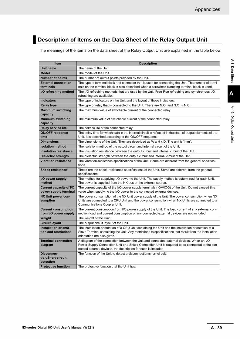
A - 39
Appendices
NX-series Digital I/O Unit User’s Manual (W521)
A-1 D
ata Sheet
A
A-1-3 D
igital Output U
nits
The meanings of the items on the data sheet of the Relay Output Unit are explained in the table below.
Description of Items on the Data Sheet of the Relay Output Unit
Item DescriptionUnit name The name of the Unit.Model The model of the Unit.Number of points The number of output points provided by the Unit.External connection terminals
The type of terminal block and connector that is used for connecting the Unit. The number of termi-nals on the terminal block is also described when a screwless clamping terminal block is used.
I/O refreshing method The I/O refreshing methods that are used by the Unit. Free-Run refreshing and synchronous I/O refreshing are available.
Indicators The type of indicators on the Unit and the layout of those indicators.Relay type The type of relay that is connected to the Unit. There are N.O. and N.O. + N.C..Maximum switching capacity
The maximum value of switchable current of the connected relay.
Minimum switching capacity
The minimum value of switchable current of the connected relay.
Relay service life The service life of the connected relay.ON/OFF response time
The delay time for which data in the internal circuit is reflected in the state of output elements of the Unit. It is described according to the ON/OFF sequence.
Dimensions The dimensions of the Unit. They are described as W x H x D. The unit is "mm".Isolation method The isolation method of the output circuit and internal circuit of the Unit.Insulation resistance The insulation resistance between the output circuit and internal circuit of the Unit.Dielectric strength The dielectric strength between the output circuit and internal circuit of the Unit.Vibration resistance The vibration-resistance specifications of the Unit. Some are different from the general specifica-
tions.Shock resistance These are the shock-resistance specifications of the Unit. Some are different from the general
specifications.I/O power supply method
The method for supplying I/O power to the Unit. The supply method is determined for each Unit. The power is supplied from the NX bus or the external source.
Current capacity of I/O power supply terminal
The current capacity of the I/O power supply terminals (IOV/IOG) of the Unit. Do not exceed this value when supplying the I/O power to the connected external devices.
NX Unit power con-sumption
The power consumption of the NX Unit power supply of the Unit. The power consumption when NX Units are connected to a CPU Unit and the power consumption when NX Units are connected to a Communications Coupler Unit.
Current consumption from I/O power supply
The current consumption from I/O power supply of the Unit. The load current of any external con-nection load and current consumption of any connected external devices are not included.
Weight The weight of the Unit.Circuit layout The output circuit layout of the Unit.Installation orienta-tion and restrictions
The installation orientation of a CPU Unit containing the Unit and the installation orientation of a Slave Terminal containing the Unit. Any restrictions to specifications that result from the installation orientation are also given.
Terminal connection diagram
A diagram of the connection between the Unit and connected external devices. When an I/O Power Supply Connection Unit or a Shield Connection Unit is required to be connected to the con-nected external devices, the description for such is included.
Disconnec-tion/Short-circuit detection
The function of the Unit to detect a disconnection/short-circuit.
Protective function The protective function that the Unit has.

Appendices
A - 40 NX-series Digital I/O Unit User’s Manual (W521)
Transistor Output Units (Screwless Clamping Terminal Block, 12 mm Width)
Unit name Transistor Output Unit Model NX-OD2154Number of points 2 points External connection
terminalsScrewless clamping terminal block (8 ter-minals)
I/O refreshing method Output refreshing with specified time stampIndicators TS indicator, output indicator Internal I/O common NPN
Rated voltage 24 VDCOperating load voltage range
15 to 28.8 VDC
Maximum value of load current
0.5 A/point, 1 A/Unit
Maximum inrush cur-rent
4.0 A/point, 10 ms max.
Leakage current 0.1 mA max.Residual voltage 1.5 V max.ON/OFF response time 300 ns max./300 ns max.
Dimensions 12 (W) x 100 (H) x 71 (D) Isolation method Digital isolator isolationInsulation resistance 20 MΩ min. between isolated circuits (at
100 VDC)Dielectric strength 510 VAC between isolated circuits for 1
minute at a leakage current of 5 mA max.I/O power supply method
Supply from the NX bus Current capacity of I/O power supply terminal
IOV: 0.5 A/terminal max., IOG: 0.5 A/termi-nal max.
NX Unit power con-sumption
• Connected to a CPU Unit0.85 W max.
• Connected to a Communications Cou-pler Unit0.45 W max.
Current consumption from I/O power supply
30 mA max.
Weight 70 g max.Circuit layout
Installation orienta-tion and restrictions
Installation orientation:• Connected to a CPU Unit
Possible in upright installation.• Connected to a Communications Coupler Unit
Possible in 6 orientations.
Restrictions: No restrictions
OUT0 to OUT1
This Unit uses a push-pull output circuit.
IOV0 to 1
IOG0 to 1
Terminal block
Inte
rnal
circ
uits
Isol
atio
n cir
cuit
Drive
circ
uit
NX bus connector (left)
I/O power supply +
I/O power supply −
I/O power supply +
I/O power supply −
NX bus connector (right)

A - 41
Appendices
NX-series Digital I/O Unit User’s Manual (W521)
A-1 D
ata Sheet
A
A-1-3 D
igital Output U
nits
Terminal connection diagram
Disconnec-tion/Short-circuit detection
Not supported. Protective function Not supported.
Two-wire type
Three-wire type
24 VDC
Transistor Output Unit
NX-OD2154
Additional I/O Power Supply Unit
IOV
IOG
IOV
IOG
IOV
IOG
IOV
IOG
A1 B1
A8 B8
A1 B1
A8 B8
OUT1
IOV
IOG
NC
OUT0
IOV
IOG
NC

Appendices
A - 42 NX-series Digital I/O Unit User’s Manual (W521)
Unit name Transistor Output Unit Model NX-OD2258Number of points 2 points External connection
terminalsScrewless clamping terminal block (8 ter-minals)
I/O refreshing method Output refreshing with specified time stampIndicators TS indicator, output indicator Internal I/O common PNP
Rated voltage 24 VDCOperating load voltage range
15 to 28.8 VDC
Maximum value of load current
0.5 A/point, 1 A/Unit
Maximum inrush cur-rent
4.0 A/point, 10 ms max.
Leakage current 0.1 mA max.Residual voltage 1.5 V max.ON/OFF response time 300 ns max./300 ns max.
Dimensions 12 (W) x 100 (H) x 71 (D) Isolation method Digital isolator isolationInsulation resistance 20 MΩ min. between isolated circuits (at
100 VDC)Dielectric strength 510 VAC between isolated circuits for 1
minute at a leakage current of 5 mA max.I/O power supply method
Supply from the NX bus Current capacity of I/O power supply terminal
IOV: 0.5 A/terminal max., IOG: 0.5 A/termi-nal max.
NX Unit power con-sumption
• Connected to a CPU Unit0.85 W max.
• Connected to a Communications Cou-pler Unit0.50 W max.
Current consumption from I/O power supply
40 mA max.
Weight 70 g max.Circuit layout
Installation orienta-tion and restrictions
Installation orientation:• Connected to a CPU Unit
Possible in upright installation.• Connected to a Communications Coupler Unit
Possible in 6 orientations.
Restrictions: No restrictions
OUT0 to OUT1
This Unit uses a push-pull output circuit.
IOV0 to 1
IOG0 to 1
Terminal block
Inte
rnal
circ
uits
Isol
atio
n cir
cuit
Drive
circ
uit
NX bus connector (left)
I/O power supply +
I/O power supply −
I/O power supply +
I/O power supply −
NX bus connector (right)

A - 43
Appendices
NX-series Digital I/O Unit User’s Manual (W521)
A-1 D
ata Sheet
A
A-1-3 D
igital Output U
nits
Terminal connection diagram
Disconnec-tion/Short-circuit detection
Not supported. Protective function With load short-circuit protection.
Two-wire type
Three-wire type24 VDC
Transistor Output Unit
NX-OD2258
Additional I/O Power Supply Unit
IOV
IOG
IOV
IOG
IOV
IOG
IOV
IOG
A1 B1
A8 B8
A1 B1
A8 B8
OUT1
IOV
IOG
NC
OUT0
IOV
IOG
NC

Appendices
A - 44 NX-series Digital I/O Unit User’s Manual (W521)
Unit name Transistor Output Unit Model NX-OD3121Number of points 4 points External connection
terminalsScrewless clamping terminal block (12 ter-minals)
I/O refreshing method Switching Synchronous I/O refreshing and Free-Run refreshingIndicators TS indicator, output indicator Internal I/O common NPN
Rated voltage 12 to 24 VDCOperating load voltage range
10.2 to 28.8 VDC
Maximum value of load current
0.5 A/point, 2 A/Unit
Maximum inrush cur-rent
4.0 A/point, 10 ms max.
Leakage current 0.1 mA max.Residual voltage 1.5 V max.ON/OFF response time 0.1 ms max./0.8 ms max.
Dimensions 12 (W) x 100 (H) x 71 (D) Isolation method Photocoupler isolationInsulation resistance 20 MΩ min. between isolated circuits (at
100 VDC)Dielectric strength 510 VAC between isolated circuits for 1
minute at a leakage current of 5 mA max.I/O power supply method
Supply from the NX bus Current capacity of I/O power supply terminal
IOV: 0.5 A/terminal max., IOG: 0.5 A/termi-nal max.
NX Unit power con-sumption
• Connected to a CPU Unit0.90 W max.
• Connected to a Communications Cou-pler Unit0.55 W max.
Current consumption from I/O power supply
10 mA max.
Weight 70 g max.Circuit layout
Installation orienta-tion and restrictions
Installation orientation:• Connected to a CPU Unit
Possible in upright installation.• Connected to a Communications Coupler Unit
Possible in 6 orientations.
Restrictions: No restrictions
OUT0 to OUT3
IOV0 to 3
IOG0 to 3
Terminal blockInte
rnal
circ
uits
NX bus connector (left)
I/O power supply +
I/O power supply −
I/O power supply +
I/O power supply −
NX bus connector (right)

A - 45
Appendices
NX-series Digital I/O Unit User’s Manual (W521)
A-1 D
ata Sheet
A
A-1-3 D
igital Output U
nits
Terminal connection diagram
Disconnec-tion/Short-circuit detection
Not supported. Protective function Not supported.
Two-wire type
Three-wire type12 to 24 VDC
Transistor Output Unit
NX-OD3121
Additional I/O Power Supply Unit
IOV
IOG
IOV
IOG
IOV
IOG
IOV
IOG
OUT0
IOG0
IOV2
IOV0
A1 B1
A8 B8
OUT2
IOG2
OUT1
IOG1
IOV3
IOV1
OUT3
IOG3
A1 B1
A8 B8

Appendices
A - 46 NX-series Digital I/O Unit User’s Manual (W521)
Unit name Transistor Output Unit Model NX-OD3153Number of points 4 points External connection
terminalsScrewless clamping terminal block (12 ter-minals)
I/O refreshing method Switching Synchronous I/O refreshing and Free-Run refreshingIndicators TS indicator, output indicator Internal I/O common NPN
Rated voltage 24 VDCOperating load voltage range
15 to 28.8 VDC
Maximum value of load current
0.5 A/point, 2 A/Unit
Maximum inrush cur-rent
4.0 A/point, 10 ms max.
Leakage current 0.1 mA max.Residual voltage 1.5 V max.ON/OFF response time 300 ns max./300 ns max.
Dimensions 12 (W) x 100 (H) x 71 (D) Isolation method Digital isolator isolationInsulation resistance 20 MΩ min. between isolated circuits (at
100 VDC)Dielectric strength 510 VAC between isolated circuits for 1
minute at a leakage current of 5 mA max.I/O power supply method
Supply from the NX bus Current capacity of I/O power supply terminal
IOV: 0.5 A/terminal max., IOG: 0.5 A/termi-nal max.
NX Unit power con-sumption
• Connected to a CPU Unit0.90 W max.
• Connected to a Communications Cou-pler Unit0.50 W max.
Current consumption from I/O power supply
30 mA max.
Weight 70 g max.Circuit layout
Installation orienta-tion and restrictions
Installation orientation:• Connected to a CPU Unit
Possible in upright installation.• Connected to a Communications Coupler Unit
Possible in 6 orientations.
Restrictions: No restrictions
OUT0 to OUT3
This Unit uses a push-pull output circuit.
IOV0 to 3
IOG0 to 3
Terminal block
Inte
rnal
circ
uits
Isol
atio
n cir
cuit
Drive
circ
uit
NX bus connector (left)
I/O power supply +
I/O power supply −
I/O power supply +
I/O power supply −
NX bus connector (right)
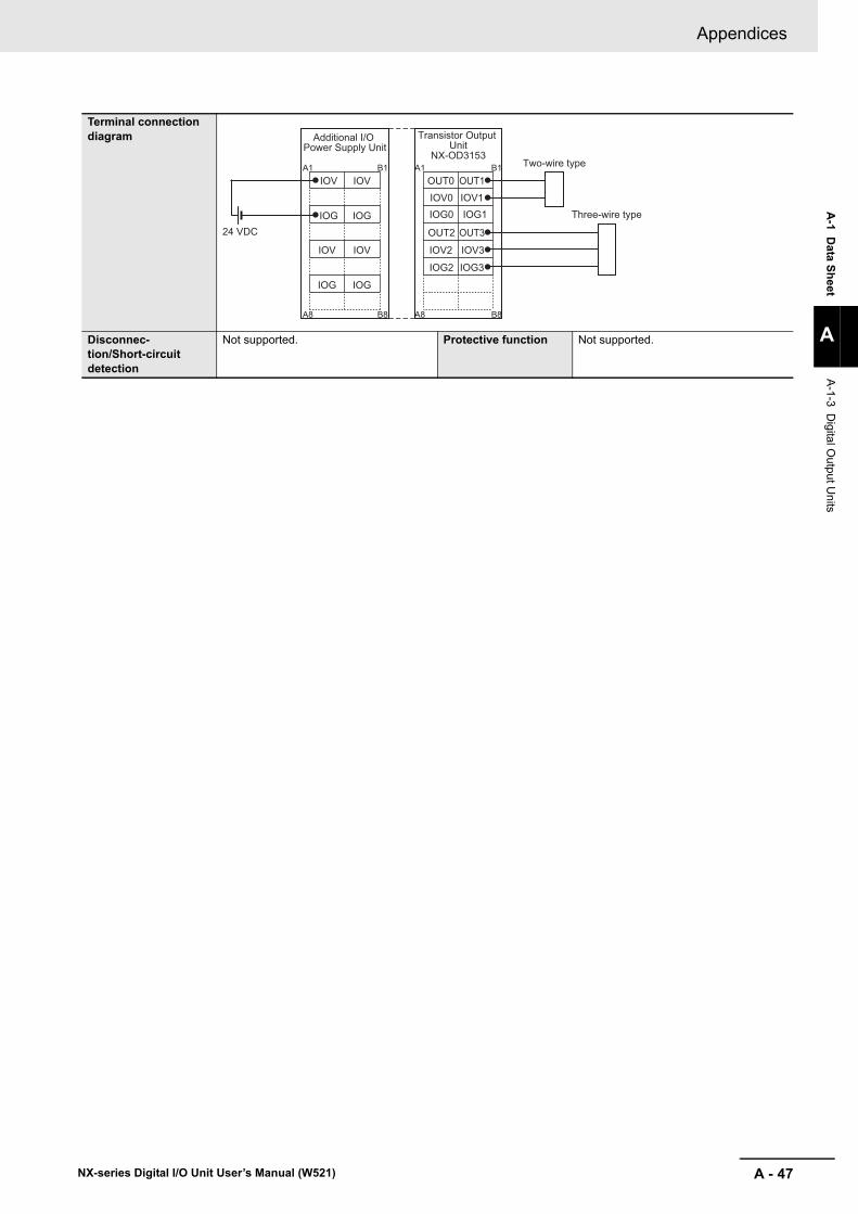
A - 47
Appendices
NX-series Digital I/O Unit User’s Manual (W521)
A-1 D
ata Sheet
A
A-1-3 D
igital Output U
nits
Terminal connection diagram
Disconnec-tion/Short-circuit detection
Not supported. Protective function Not supported.
Two-wire type
Three-wire type24 VDC
Transistor Output Unit
NX-OD3153
Additional I/O Power Supply Unit
IOV
IOG
IOV
IOG
IOV
IOG
IOV
IOG
OUT0
IOG0
IOV2
IOV0
A1 B1
A8 B8
OUT2
IOG2
OUT1
IOG1
IOV3
IOV1
OUT3
IOG3
A1 B1
A8 B8

Appendices
A - 48 NX-series Digital I/O Unit User’s Manual (W521)
Unit name Transistor Output Unit Model NX-OD3256Number of points 4 points External connection
terminalsScrewless clamping terminal block (12 ter-minals)
I/O refreshing method Switching Synchronous I/O refreshing and Free-Run refreshingIndicators TS indicator, output indicator Internal I/O common PNP
Rated voltage 24 VDCOperating load voltage range
15 to 28.8 VDC
Maximum value of load current
0.5 A/point, 2 A/Unit
Maximum inrush cur-rent
4.0 A/point, 10 ms max.
Leakage current 0.1 mA max.Residual voltage 1.5 V max.ON/OFF response time 0.5 ms max./1.0 ms max.
Dimensions 12 (W) x 100 (H) x 71 (D) Isolation method Photocoupler isolationInsulation resistance 20 MΩ min. between isolated circuits (at
100 VDC)Dielectric strength 510 VAC between isolated circuits for 1
minute at a leakage current of 5 mA max.I/O power supply method
Supply from the NX bus Current capacity of I/O power supply terminal
IOV: 0.5 A/terminal max., IOG: 0.5 A/termi-nal max.
NX Unit power con-sumption
• Connected to a CPU Unit0.90 W max.
• Connected to a Communications Cou-pler Unit0.55 W max.
Current consumption from I/O power supply
20 mA max.
Weight 70 g max.Circuit layout
Installation orienta-tion and restrictions
Installation orientation:• Connected to a CPU Unit
Possible in upright installation.• Connected to a Communications Coupler Unit
Possible in 6 orientations.
Restrictions: No restrictions
OUT0 to OUT3
IOV0 to 3
IOG0 to 3
Terminal block
Inte
rnal
circ
uits
Short
-circu
it prot
ectio
n
NX bus connector (left)
I/O power supply +
I/O power supply −
I/O power supply +
I/O power supply −
NX bus connector (right)

A - 49
Appendices
NX-series Digital I/O Unit User’s Manual (W521)
A-1 D
ata Sheet
A
A-1-3 D
igital Output U
nits
Terminal connection diagram
Disconnec-tion/Short-circuit detection
Not supported. Protective function With load short-circuit protection.
Two-wire type
Three-wire type
24 VDC
Transistor Output Unit
NX-OD3256
Additional I/O Power Supply Unit
IOV
IOG
IOV
IOG
IOV
IOG
IOV
IOG
OUT0
IOG0
IOV2
IOV0
A1 B1
A8 B8
OUT2
IOG2
OUT1
IOG1
IOV3
IOV1
OUT3
IOG3
A1 B1
A8 B8

Appendices
A - 50 NX-series Digital I/O Unit User’s Manual (W521)
Unit name Transistor Output Unit Model NX-OD3257Number of points 4 points External connection
terminalsScrewless clamping terminal block (12 ter-minals)
I/O refreshing method Switching Synchronous I/O refreshing and Free-Run refreshingIndicators TS indicator, output indicator Internal I/O common PNP
Rated voltage 24 VDCOperating load voltage range
15 to 28.8 VDC
Maximum value of load current
0.5 A/point, 2 A/Unit
Maximum inrush cur-rent
4.0 A/point, 10 ms max.
Leakage current 0.1 mA max.Residual voltage 1.5 V max.ON/OFF response time 300 ns max./300 ns max.
Dimensions 12 (W) x 100 (H) x 71 (D) Isolation method Digital isolator isolationInsulation resistance 20 MΩ min. between isolated circuits (at
100 VDC)Dielectric strength 510 VAC between isolated circuits for 1
minute at a leakage current of 5 mA max.I/O power supply method
Supply from the NX bus Current capacity of I/O power supply terminal
IOV: 0.5 A/terminal max., IOG: 0.5 A/termi-nal max.
NX Unit power con-sumption
• Connected to a CPU Unit0.85 W max.
• Connected to a Communications Cou-pler Unit0.50 W max.
Current consumption from I/O power supply
40 mA max.
Weight 70 g max.Circuit layout
Installation orienta-tion and restrictions
Installation orientation:• Connected to a CPU Unit
Possible in upright installation.• Connected to a Communications Coupler Unit
Possible in 6 orientations.
Restrictions: No restrictions
Shor
t-circ
uit
prote
ction
OUT0 to OUT3
This Unit uses a push-pull output circuit.
IOV0 to 3
IOG0 to 3
Terminal block
Inte
rnal
circ
uits
Isol
atio
n cir
cuit
Drive
circ
uit
NX bus connector (left)
I/O power supply +
I/O power supply −
I/O power supply +
I/O power supply −
NX bus connector (right)

A - 51
Appendices
NX-series Digital I/O Unit User’s Manual (W521)
A-1 D
ata Sheet
A
A-1-3 D
igital Output U
nits
Terminal connection diagram
Disconnec-tion/Short-circuit detection
Not supported. Protective function With load short-circuit protection.
Two-wire type
Three-wire type
24 VDC
Transistor Output Unit
NX-OD3257
Additional I/O Power Supply Unit
IOV
IOG
IOV
IOG
IOV
IOG
IOV
IOG
OUT0
IOG0
IOV2
IOV0
A1 B1
A8 B8
OUT2
IOG2
OUT1
IOG1
IOV3
IOV1
OUT3
IOG3
A1 B1
A8 B8

Appendices
A - 52 NX-series Digital I/O Unit User’s Manual (W521)
Unit name Transistor Output Unit Model NX-OD3268Number of points 4 points External connection
terminalsScrewless clamping terminal block (16 ter-minals)
I/O refreshing method Switching Synchronous I/O refreshing and Free-Run refreshingIndicators TS indicator, output indicator Internal I/O common PNP
Rated voltage 24 VDCOperating load voltage range
15 to 28.8 VDC
Maximum value of load current
2 A/point, 8 A/Unit
Maximum inrush cur-rent
4.0 A/point, 10 ms max.
Leakage current 0.1 mA max.Residual voltage 1.5 V max.ON/OFF response time 0.5 ms max./1.0 ms max.
Dimensions 12 (W) x 100 (H) x 71 (D) Isolation method Photocoupler isolationInsulation resistance 20 MΩ min. between isolated circuits (at
100 VDC)Dielectric strength 510 VAC between isolated circuits for 1
minute at a leakage current of 5 mA max.I/O power supply method
Supply from external source Current capacity of I/O power supply terminal
IOV: 2 A/terminal max., IOG: 2 A/terminal max., COM (+V): 4 A/terminal max., 0V: 4 A/terminal max.
NX Unit power con-sumption
• Connected to a CPU Unit0.85 W max.
• Connected to a Communications Cou-pler Unit0.50 W max.
Current consumption from I/O power supply
20 mA max.
Weight 70 g max.Circuit layout
Installation orienta-tion and restrictions
Installation orientation:• Connected to a CPU Unit
Possible in upright installation.• Connected to a Communications Coupler Unit
Possible in 6 orientations.
Restrictions: No restrictions
OUT 0 to OUT 3
IOG 0 to IOG 3
IOV 0 to IOV 3COM (+V)
0VI/O power supply +NX bus
connector(left)
I/O power supply −
NX busconnector(right)
I/O power supply +I/O power supply −
Terminal block
Inte
rnal
circ
uits
Shor
t-circ
uit
prot
ectio
n
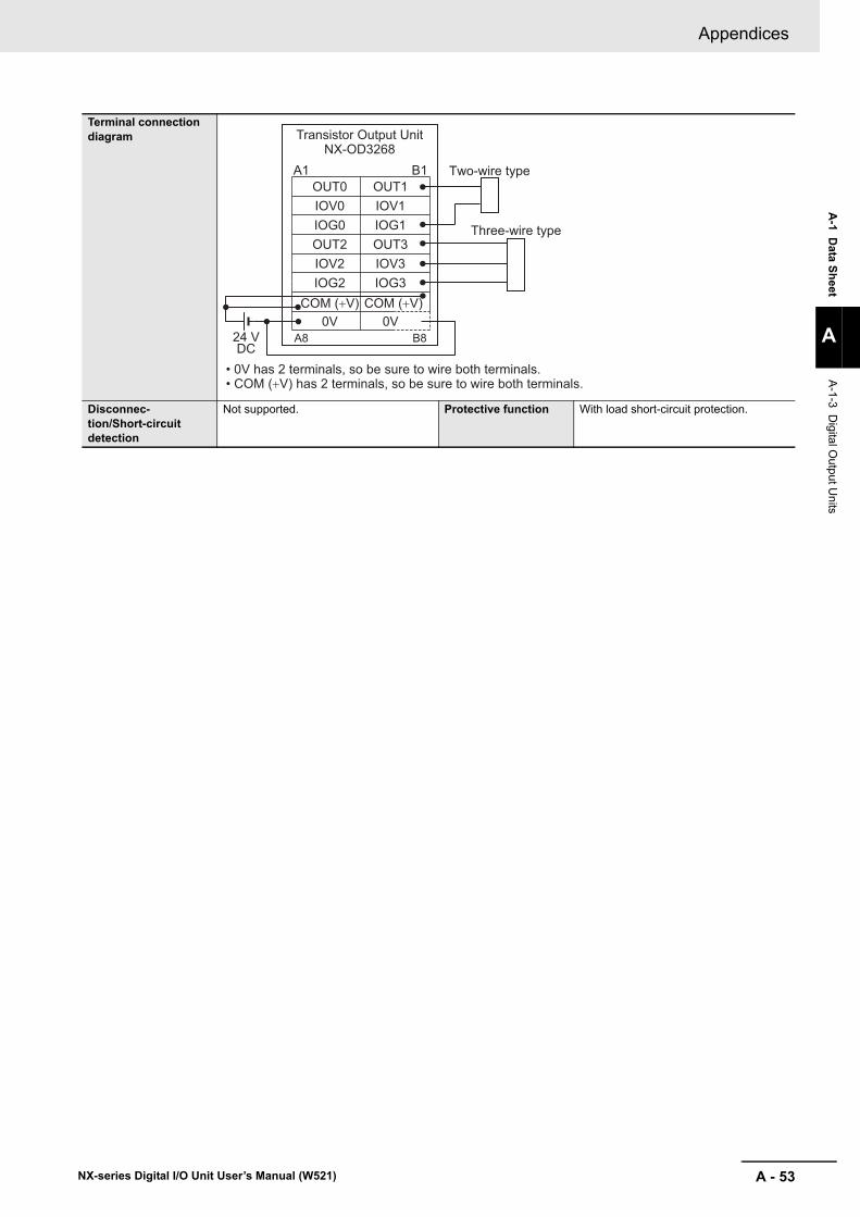
A - 53
Appendices
NX-series Digital I/O Unit User’s Manual (W521)
A-1 D
ata Sheet
A
A-1-3 D
igital Output U
nits
Terminal connection diagram
Disconnec-tion/Short-circuit detection
Not supported. Protective function With load short-circuit protection.
OUT0
IOG0
IOV2
IOV0
A1 B1
A8 B8
OUT2
IOG2
OUT1
IOG1
IOV3
IOV1
OUT3
IOG3COM (+V) COM (+V)
0V 0V
Transistor Output UnitNX-OD3268
Two-wire type
Three-wire type
24 VDC
• 0V has 2 terminals, so be sure to wire both terminals.• COM (+V) has 2 terminals, so be sure to wire both terminals.

Appendices
A - 54 NX-series Digital I/O Unit User’s Manual (W521)
Unit name Transistor Output Unit Model NX-OD4121Number of points 8 points External connection
terminalsScrewless clamping terminal block (16 ter-minals)
I/O refreshing method Switching Synchronous I/O refreshing and Free-Run refreshingIndicators TS indicator, output indicator Internal I/O common NPN
Rated voltage 12 to 24 VDCOperating load voltage range
10.2 to 28.8 VDC
Maximum value of load current
0.5 A/point, 4 A/Unit
Maximum inrush cur-rent
4.0 A/point, 10 ms max.
Leakage current 0.1 mA max.Residual voltage 1.5 V max.ON/OFF response time 0.1 ms max./0.8 ms max.
Dimensions 12 (W) x 100 (H) x 71 (D) Isolation method Photocoupler isolationInsulation resistance 20 MΩ min. between isolated circuits (at
100 VDC)Dielectric strength 510 VAC between isolated circuits for 1
minute at a leakage current of 5 mA max.I/O power supply method
Supply from the NX bus Current capacity of I/O power supply terminal
IOV: 0.5 A/terminal max.
NX Unit power con-sumption
• Connected to a CPU Unit0.90 W max.
• Connected to a Communications Cou-pler Unit0.55 W max.
Current consumption from I/O power supply
10 mA max.
Weight 70 g max.Circuit layout
Installation orienta-tion and restrictions
Installation orientation:• Connected to a CPU Unit
Possible in upright installation.• Connected to a Communications Coupler Unit
Possible in 6 orientations.
Restrictions: No restrictions
OUT0 to OUT7
IOV0 to 7Terminal block
Inte
rnal
circ
uits
NX bus connector (left)
I/O power supply +
I/O power supply −
I/O power supply +
I/O power supply −
NX bus connector (right)

A - 55
Appendices
NX-series Digital I/O Unit User’s Manual (W521)
A-1 D
ata Sheet
A
A-1-3 D
igital Output U
nits
Terminal connection diagram
Disconnec-tion/Short-circuit detection
Not supported. Protective function Not supported.
Two-wire type
Three-wire type12 to 24 VDC
Transistor Output Unit
NX-OD4121
Additional I/O Power Supply Unit
I/O Power Supply Connection Unit
OUT0
OUT2
OUT4
IOV0
A1 B1
A8 B8
IOV2
IOV4
OUT1
OUT3
OUT5
IOV1
IOV3
IOV6
OUT6
IOV7
OUT7IOV5
IOV
IOG
IOV
IOG
IOV
IOG
IOV
IOG
A1 B1
A8 B8
A1 B1
A8 B8
IOG
IOG
IOG
IOG
IOG
IOG
IOG
IOG
IOG
IOG
IOG
IOG
IOG
IOG
IOG
IOG

Appendices
A - 56 NX-series Digital I/O Unit User’s Manual (W521)
Unit name Transistor Output Unit Model NX-OD4256Number of points 8 points External connection
terminalsScrewless clamping terminal block (16 ter-minals)
I/O refreshing method Switching Synchronous I/O refreshing and Free-Run refreshingIndicators TS indicator, output indicator Internal I/O common PNP
Rated voltage 24 VDCOperating load voltage range
15 to 28.8 VDC
Maximum value of load current
0.5 A/point, 4 A/Unit
Maximum inrush cur-rent
4.0 A/point, 10 ms max.
Leakage current 0.1 mA max.Residual voltage 1.5 V max.ON/OFF response time 0.5 ms max./1.0 ms max.
Dimensions 12 (W) x 100 (H) x 71 (D) Isolation method Photocoupler isolationInsulation resistance 20 MΩ min. between isolated circuits (at
100 VDC)Dielectric strength 510 VAC between isolated circuits for 1
minute at a leakage current of 5 mA max.I/O power supply method
Supply from the NX bus Current capacity of I/O power supply terminal
IOG: 0.5 A/terminal max.
NX Unit power con-sumption
• Connected to a CPU Unit1.00 W max.
• Connected to a Communications Cou-pler Unit0.65 W max.
Current consumption from I/O power supply
30 mA max.
Weight 70 g max.Circuit layout
Installation orienta-tion and restrictions
Installation orientation:• Connected to a CPU Unit
Possible in upright installation.• Connected to a Communications Coupler Unit
Possible in 6 orientations.
Restrictions: No restrictions
OUT0 to OUT7
IOG0 to 7
Terminal block
Inte
rnal
circ
uits
Short
-circu
it prot
ectio
n
NX bus connector (left)
I/O power supply +
I/O power supply −
I/O power supply +
I/O power supply −
NX bus connector (right)

A - 57
Appendices
NX-series Digital I/O Unit User’s Manual (W521)
A-1 D
ata Sheet
A
A-1-3 D
igital Output U
nits
Terminal connection diagram
Disconnec-tion/Short-circuit detection
Not supported. Protective function With load short-circuit protection.
Two-wire type
Three-wire type
24 VDC
Transistor Output Unit
NX-OD4256
Additional I/O Power Supply Unit
I/O Power Supply Connection Unit
A1 B1
A8 B8
OUT7
IOV
IOG
IOV
IOG
IOV
IOG
IOV
IOG
A1 B1
A8 B8
A1 B1
A8 B8
IOV
IOV
IOV
IOV
IOV
IOV
IOV
IOV
IOV
IOV
IOV
IOV
IOV
IOV
IOV
IOV
OUT0
OUT2
OUT4
IOG0
IOG2
IOG4
OUT1
OUT3
OUT5
IOG1
IOG3
IOG6OUT6
IOG7
IOG5

Appendices
A - 58 NX-series Digital I/O Unit User’s Manual (W521)
Unit name Transistor Output Unit Model NX-OD5121Number of points 16 points External connection
terminalsScrewless clamping terminal block (16 ter-minals)
I/O refreshing method Switching Synchronous I/O refreshing and Free-Run refreshingIndicators TS indicator, output indicator Internal I/O common NPN
Rated voltage 12 to 24 VDCOperating load voltage range
10.2 to 28.8 VDC
Maximum value of load current
0.5 A/point, 4 A/Unit
Maximum inrush cur-rent
4.0 A/point, 10 ms max.
Leakage current 0.1 mA max.Residual voltage 1.5 V max.ON/OFF response time 0.1 ms max./0.8 ms max.
Dimensions 12 (W) x 100 (H) x 71 (D) Isolation method Photocoupler isolationInsulation resistance 20 MΩ min. between isolated circuits (at
100 VDC)Dielectric strength 510 VAC between isolated circuits for 1
minute at a leakage current of 5 mA max.I/O power supply method
Supply from the NX bus Current capacity of I/O power supply terminal
Without I/O power supply terminals
NX Unit power con-sumption
• Connected to a CPU Unit1.00 W max.
• Connected to a Communications Cou-pler Unit0.65 W max.
Current consumption from I/O power supply
20 mA max.
Weight 70 g max.Circuit layout
Installation orienta-tion and restrictions
Installation orientation:• Connected to a CPU Unit
Possible in upright installation.• Connected to a Communications Coupler Unit
Possible in 6 orientations.
Restrictions: No restrictions
OUT0 to OUT15 Terminal block
Inte
rnal
circ
uits
NX bus connector (left)
I/O power supply +
I/O power supply −
I/O power supply +
I/O power supply −
NX bus connector (right)

A - 59
Appendices
NX-series Digital I/O Unit User’s Manual (W521)
A-1 D
ata Sheet
A
A-1-3 D
igital Output U
nits
Terminal connection diagram
Disconnec-tion/Short-circuit detection
Not supported. Protective function Not supported.
Two-wire type
Three-wire typ
12 to 24 VDC
Transistor Output Unit
NX-OD5121
Additional I/O Power Supply Unit
I/O Power Supply Connection Unit
I/O Power Supply Connection Unit
OUT0
OUT4
OUT8
OUT2
A1 B1
A8 B8
OUT6
OUT10
OUT1
OUT5
OUT9
OUT3
OUT7
OUT14
OUT12
OUT15
OUT13
OUT11
IOV
IOG
IOV
IOG
IOV
IOG
IOV
IOG
A1 B1
A8 B8
A1 B1
A8 B8
A1 B1
A8 B8
IOV
IOV
IOV
IOV
IOV
IOV
IOV
IOV
IOV
IOV
IOV
IOV
IOV
IOV
IOV
IOV
IOG
IOG
IOG
IOG
IOG
IOG
IOG
IOG
IOG
IOG
IOG
IOG
IOG
IOG
IOG
IOG

Appendices
A - 60 NX-series Digital I/O Unit User’s Manual (W521)
Unit name Transistor Output Unit Model NX-OD5256Number of points 16 points External connection
terminalsScrewless clamping terminal block (16 ter-minals)
I/O refreshing method Switching Synchronous I/O refreshing and Free-Run refreshingIndicators TS indicator, output indicator Internal I/O common PNP
Rated voltage 24 VDCOperating load voltage range
15 to 28.8 VDC
Maximum value of load current
0.5 A/point, 4 A/Unit
Maximum inrush cur-rent
4.0 A/point, 10 ms max.
Leakage current 0.1 mA max.Residual voltage 1.5 V max.ON/OFF response time 0.5 ms max./1.0 ms max.
Dimensions 12 (W) x 100 (H) x 71 (D) Isolation method Photocoupler isolationInsulation resistance 20 MΩ min. between isolated circuits (at
100 VDC)Dielectric strength 510 VAC between isolated circuits for 1
minute at a leakage current of 5 mA max.I/O power supply method
Supply from the NX bus Current capacity of I/O power supply terminal
Without I/O power supply terminals
NX Unit power con-sumption
• Connected to a CPU Unit1.10 W max.
• Connected to a Communications Cou-pler Unit0.70 W max.
Current consumption from I/O power supply
40 mA max.
Weight 70 g max.Circuit layout
Installation orienta-tion and restrictions
Installation orientation:• Connected to a CPU Unit
Possible in upright installation.• Connected to a Communications Coupler Unit
Possible in 6 orientations.
Restrictions: No restrictions
OUT0 to OUT15 Terminal blockInte
rnal
circ
uits
Short
-circu
it prot
ectio
n
NX bus connector (left)
I/O power supply +
I/O power supply −
I/O power supply +
I/O power supply −
NX bus connector (right)

A - 61
Appendices
NX-series Digital I/O Unit User’s Manual (W521)
A-1 D
ata Sheet
A
A-1-3 D
igital Output U
nits
Terminal connection diagram
Disconnec-tion/Short-circuit detection
Not supported. Protective function With load short-circuit protection.
Two-wire type
Three-wire type
24 VDC
Transistor Output Unit
NX-OD5256
Additional I/O Power Supply Unit
I/O Power Supply Connection Unit
I/O Power Supply Connection Unit
A1 B1
A8 B8
IOV
IOG
IOV
IOG
IOV
IOG
IOV
IOG
A1 B1
A8 B8
A1 B1
A8 B8
A1 B1
A8 B8
IOV
IOV
IOV
IOV
IOV
IOV
IOV
IOV
IOV
IOV
IOV
IOV
IOV
IOV
IOV
IOV
IOG
IOG
IOG
IOG
IOG
IOG
IOG
IOG
IOG
IOG
IOG
IOG
IOG
IOG
IOG
IOG
OUT0
OUT4
OUT8
OUT2
OUT6
OUT10
OUT1
OUT5
OUT9
OUT3
OUT7
OUT14
OUT12
OUT15
OUT13OUT11

Appendices
A - 62 NX-series Digital I/O Unit User’s Manual (W521)
Transistor Output Units (M3 Screw Terminal Block, 30 mm Width)
Unit name Transistor Output Unit Model NX-OD5121-1Number of points 16 points External connection
terminalsM3 screw terminal block (18 terminals)
I/O refreshing method Switching Synchronous I/O refreshing and Free-Run refreshingIndicators TS indicator, output indicator Internal I/O common NPN
Rated voltage 12 to 24 VDCOperating load voltage range
10.2 to 28.8 VDC
Maximum value of load current
0.5 A/point, 5 A/Unit
Maximum inrush cur-rent
4.0 A/point, 10 ms max.
Leakage current 0.1 mA max.Residual voltage 1.5 V max.ON/OFF response time 0.1 ms max./0.8 ms max.
Dimensions 30 (W) x 100 (H) x 71 (D) Isolation method Photocoupler isolationInsulation resistance 20 MΩ min. between isolated circuits (at
100 VDC)Dielectric strength 510 VAC between isolated circuits for 1
minute at a leakage current of 5 mA max.I/O power supply method
Supply from the external source Current capacity of I/O power supply terminal
Without I/O power supply terminals
NX Unit power con-sumption
• Connected to a CPU Unit0.90 W max.
• Connected to a Communications Cou-pler Unit0.60 W max.
Current consumption from I/O power supply
30 mA max.
Weight 125 g max.Circuit layout
Installation orienta-tion and restrictions
Installation orientation:• Connected to a CPU Unit
Possible in upright installation.• Connected to a Communications Coupler Unit
Possible in 6 orientations.
Restrictions: No restrictions
OUT0 to OUT15
COM
+V
I/O power supply +NX bus
connector(left)
I/O power supply −
NX busconnector(right)
I/O power supply +I/O power supply −
Terminal block
Inte
rnal
circ
uits

A - 63
Appendices
NX-series Digital I/O Unit User’s Manual (W521)
A-1 D
ata Sheet
A
A-1-3 D
igital Output U
nits
Terminal connection diagram
Disconnec-tion/Short-circuit detection
Not supported. Protective function Not supported.
A0A B
A2
A4
A1
A3
A5
A7A8
A6
B0
B2
B4
B1
B3
B5
B7B8
B6
OUT2
OUT6
OUT0
OUT4
OUT8
OUT12OUT14
COM
OUT10
TerminalSignal nameSignal name
12 to 24 VDC
OUT3
OUT7
OUT1
OUT5
OUT9
OUT13OUT15+V
OUT11
LLLLLLLL
LLLLLLLL
• The terminal number in the terminal connection diagram is the specifications for this manual. They are not printed on the Units.
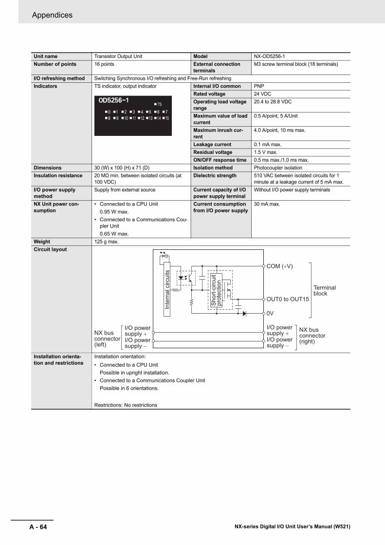
Appendices
A - 64 NX-series Digital I/O Unit User’s Manual (W521)
Unit name Transistor Output Unit Model NX-OD5256-1Number of points 16 points External connection
terminalsM3 screw terminal block (18 terminals)
I/O refreshing method Switching Synchronous I/O refreshing and Free-Run refreshingIndicators TS indicator, output indicator Internal I/O common PNP
Rated voltage 24 VDCOperating load voltage range
20.4 to 28.8 VDC
Maximum value of load current
0.5 A/point, 5 A/Unit
Maximum inrush cur-rent
4.0 A/point, 10 ms max.
Leakage current 0.1 mA max.Residual voltage 1.5 V max.ON/OFF response time 0.5 ms max./1.0 ms max.
Dimensions 30 (W) x 100 (H) x 71 (D) Isolation method Photocoupler isolationInsulation resistance 20 MΩ min. between isolated circuits (at
100 VDC)Dielectric strength 510 VAC between isolated circuits for 1
minute at a leakage current of 5 mA max.I/O power supply method
Supply from external source Current capacity of I/O power supply terminal
Without I/O power supply terminals
NX Unit power con-sumption
• Connected to a CPU Unit0.95 W max.
• Connected to a Communications Cou-pler Unit0.65 W max.
Current consumption from I/O power supply
30 mA max.
Weight 125 g max.Circuit layout
Installation orienta-tion and restrictions
Installation orientation:• Connected to a CPU Unit
Possible in upright installation.• Connected to a Communications Coupler Unit
Possible in 6 orientations.
Restrictions: No restrictions
OUT0 to OUT15
0V
COM (+V)
I/O power supply +NX bus
connector(left)
I/O power supply −
NX busconnector(right)
I/O power supply +I/O power supply −
Terminalblock
Inte
rnal
circ
uits
Shor
t-circ
uit
prot
ectio
n

A - 65
Appendices
NX-series Digital I/O Unit User’s Manual (W521)
A-1 D
ata Sheet
A
A-1-3 D
igital Output U
nits
Terminal connection diagram
Disconnec-tion/Short-circuit detection
Not supported. Protective function With load short-circuit protection.
A0A B
A2
A4
A1
A3
A5
A7A8
A6
B0
B2
B4
B1
B3
B5
B7B8
B6
OUT2
OUT6
OUT0
OUT4
OUT8
OUT12OUT14
0V
OUT10
TerminalSignal nameSignal name
24 VDC
OUT3
OUT7
OUT1
OUT5
OUT9
OUT13OUT15COM (+V)
OUT11
LLLLLLLL
LLLLLLLL
• The terminal number in the terminal connection diagram is the specifications for this manual. They are not printed on the Units.

Appendices
A - 66 NX-series Digital I/O Unit User’s Manual (W521)
Transistor Output Units (MIL Connector, 30 mm Width)
Unit name Transistor Output Unit Model NX-OD5121-5Number of points 16 points External connection
terminalsMIL connector (20 terminals)
I/O refreshing method Switching Synchronous I/O refreshing and Free-Run refreshingIndicators TS indicator, output indicator Internal I/O common NPN
Rated voltage 12 to 24 VDCOperating load voltage range
10.2 to 28.8 VDC
Maximum value of load current
0.5 A/point, 2 A/Unit
Maximum inrush cur-rent
4.0 A/point, 10 ms max.
Leakage current 0.1 mA max.Residual voltage 1.5 V max.ON/OFF response time 0.1 ms max./0.8 ms max.
Dimensions 30 (W) x 100 (H) x 71 (D) Isolation method Photocoupler isolationInsulation resistance 20 MΩ min. between isolated circuits (at
100 VDC)Dielectric strength 510 VAC between isolated circuits for 1
minute at a leakage current of 5 mA max.I/O power supply method
Supply from external source Current capacity of I/O power supply terminal
Without I/O power supply terminals
NX Unit power con-sumption
• Connected to a CPU Unit0.95 W max.
• Connected to a Communications Cou-pler Unit0.60 W max.
Current consumption from I/O power supply
30 mA max.
Weight 80 g max.Circuit layout
Installation orienta-tion and restrictions
Installation orientation:• Connected to a CPU Unit
Possible in upright installation.• Connected to a Communications Coupler Unit
Possible in 6 orientations.
Restrictions: No restrictions
OUT0 to OUT15
COM
+V+V
COMI/O power supply +NX bus
connector(left)
I/O power supply −
NX busconnector(right)
I/O power supply +I/O power supply −
Connector
Inte
rnal
circ
uits

A - 67
Appendices
NX-series Digital I/O Unit User’s Manual (W521)
A-1 D
ata Sheet
A
A-1-3 D
igital Output U
nits
Terminal connection diagram
Disconnec-tion/Short-circuit detection
Not supported. Protective function Not supported.
1
5
9
3
7
11
151719
13
+V
OUT15
OUT13
COM
OUT14
OUT12
OUT10OUT09OUT08
OUT11
2
6
10
4
8
12
161820
14
12 to 24 VDC +V
OUT07
OUT05
COM
OUT06
OUT04
OUT02OUT01OUT00
OUT03
L LL LL LL LL LL LL LL L
Connectorpin
Signalname
Signalname
• Be sure to wire both pins 3 and 4 (COM).• Be sure to wire both pins 1 and 2 (+V).

Appendices
A - 68 NX-series Digital I/O Unit User’s Manual (W521)
Unit name Transistor Output Unit Model NX-OD5256-5Number of points 16 points External connection
terminalsMIL connector (20 terminals)
I/O refreshing method Switching Synchronous I/O refreshing and Free-Run refreshingIndicators TS indicator, output indicator Internal I/O common PNP
Rated voltage 24 VDCOperating load voltage range
20.4 to 28.8 VDC
Maximum value of load current
0.5 A/point, 2 A/Unit
Maximum inrush cur-rent
4.0 A/point, 10 ms max.
Leakage current 0.1 mA max.Residual voltage 1.5 V max.ON/OFF response time 0.5 ms max./1.0 ms max.
Dimensions 30 (W) x 100 (H) x 71 (D) Isolation method Photocoupler isolationInsulation resistance 20 MΩ min. between isolated circuits (at
100 VDC)Dielectric strength 510 VAC between isolated circuits for 1
minute at a leakage current of 5 mA max.I/O power supply method
Supplied from external source. Current capacity of I/O power supply terminal
Without I/O power supply terminals
NX Unit power con-sumption
• Connected to a CPU Unit1.00 W max.
• Connected to a Communications Cou-pler Unit0.70 W max.
Current consumption from I/O power supply
40 mA max.
Weight 85 g max.Circuit layout
Installation orienta-tion and restrictions
Installation orientation:• Connected to a CPU Unit
Possible in upright installation.• Connected to a Communications Coupler Unit
Possible in 6 orientations.
Restrictions: No restrictions
OUT0 to OUT15
0V
COM (+V)COM (+V)
0VI/O power supply +NX bus
connector(left)
I/O power supply −
NX busconnector(right)
I/O power supply +I/O power supply −
Connector
Inte
rnal
circ
uits
Shor
t-circ
uit
prot
ectio
n

A - 69
Appendices
NX-series Digital I/O Unit User’s Manual (W521)
A-1 D
ata Sheet
A
A-1-3 D
igital Output U
nits
Terminal connection diagram
Disconnec-tion/Short-circuit detection
Not supported. Protective function With load short-circuit protection.
1
5
9
3
7
11
151719
13
COM (+V)
OUT15
OUT13
0V
OUT14
OUT12
OUT10OUT09OUT08
OUT11
2
6
10
4
8
12
161820
14
24 VDC COM (+V)
OUT07
OUT05
0V
OUT06
OUT04
OUT02OUT01OUT00
OUT03
L LL LL LL LL LL LL LL L
Connectorpin
Signalname
Signalname
• Be sure to wire both pins 1 and 2 (COM (+V)).• Be sure to wire both pins 3 and 4 (0V).

Appendices
A - 70 NX-series Digital I/O Unit User’s Manual (W521)
Unit name Transistor Output Unit Model NX-OD6121-5Number of points 32 points External connection
terminalsMIL connector (40 terminals)
I/O refreshing method Switching Synchronous I/O refreshing and Free-Run refreshingIndicators TS indicator, output indicator Internal I/O common NPN
Rated voltage 12 to 24 VDCOperating load voltage range
10.2 to 28.8 VDC
Maximum value of load current
0.5 A/point, 2 A/common, 4 A/Unit
Maximum inrush cur-rent
4.0 A/point, 10 ms max.
Leakage current 0.1 mA max.Residual voltage 1.5 V max.ON/OFF response time 0.1 ms max./0.8 ms max.
Dimensions 30 (W) x 100 (H) x 71 (D) Isolation method Photocoupler isolationInsulation resistance 20 MΩ min. between isolated circuits (at
100 VDC)Dielectric strength 510 VAC between isolated circuits for 1
minute at a leakage current of 5 mA max.I/O power supply method
Supply from external source Current capacity of I/O power supply terminal
Without I/O power supply terminals
NX Unit power con-sumption
• Connected to a CPU Unit1.00 W max.
• Connected to a Communications Cou-pler Unit0.80 W max.
Current consumption from I/O power supply
50 mA max.
Weight 90 g max.Circuit layout
Installation orienta-tion and restrictions
Installation orientation:• Connected to a CPU Unit
Possible in upright installation.• Connected to a Communications Coupler Unit
Possible in 6 orientations.
Restrictions: No restrictions
OUT0 to OUT15
COM0
+V0
OUT16 to OUT31
COM1
+V1
+V0
COM0
+V1
COM1I/O power supply +NX bus
connector(left)
I/O power supply −
NX busconnector(right)
I/O power supply +I/O power supply −
Inte
rnal
circ
uits
Connector

A - 71
Appendices
NX-series Digital I/O Unit User’s Manual (W521)
A-1 D
ata Sheet
A
A-1-3 D
igital Output U
nits
Terminal connection diagram
Disconnec-tion/Short-circuit detection
Not supported. Protective function Not supported.
1
5
9
3
7
11
151719
13
+V1
OUT31
OUT29
COM1
OUT30
OUT28
OUT26OUT25OUT24
OUT27
2
6
10
4
8
12
161820
14
21
25
29
23
27
31
353739
33
22
26
30
24
28
32
363840
34
+V1
OUT23
OUT21
COM1
OUT22
OUT20
OUT18OUT17OUT16
OUT19
+V0
OUT15
OUT13
COM0
OUT14
OUT12
OUT10OUT09OUT08
OUT11
+V0
OUT07
OUT05
COM0
OUT06
OUT04
OUT02OUT01OUT00
OUT03
LLLLLLL
LLLLLLLL
LLLLLLL
LLLLLLLL
Connectorpin
Signalname
Signalname
• Be sure to wire both pins 21 and 22 (+V0).
• Be sure to wire both pins 23 and 24 (COM0).
• Be sure to wire both pins 1 and 2 (+V1).
• Be sure to wire both pins 3 and 4 (COM1).
12 to 24 VDC
12 to 24 VDC

Appendices
A - 72 NX-series Digital I/O Unit User’s Manual (W521)
Unit name Transistor Output Unit Model NX-OD6256-5Number of points 32 points External connection
terminalsMIL connector (40 terminals)
I/O refreshing method Switching Synchronous I/O refreshing and Free-Run refreshingIndicators TS indicator, output indicator Internal I/O common PNP
Rated voltage 24 VDCOperating load voltage range
20.4 to 28.8 VDC
Maximum value of load current
0.5 A/point, 2 A/common, 4 A/Unit
Maximum inrush cur-rent
4.0 A/point, 10 ms max.
Leakage current 0.1 mA max.Residual voltage 1.5 V max.ON/OFF response time 0.5 ms max./1.0 ms max.
Dimensions 30 (W) x 100 (H) x 71 (D) Isolation method Photocoupler isolationInsulation resistance 20 MΩ min. between isolated circuits (at
100 VDC)Dielectric strength 510 VAC between isolated circuits for 1
minute at a leakage current of 5 mA max.I/O power supply method
Supply from external source Current capacity of I/O power supply terminal
Without I/O power supply terminals
NX Unit power con-sumption
• Connected to a CPU Unit1.30 W max.
• Connected to a Communications Cou-pler Unit1.00 W max.
Current consumption from I/O power supply
80 mA max.
Weight 95 g max.Circuit layout
Installation orienta-tion and restrictions
Installation orientation:• Connected to a CPU Unit
Possible in upright installation.• Connected to a Communications Coupler Unit
Possible in 6 orientations.
Restrictions: No restrictions
OUT0 to OUT150V0
COM0 (+V)COM0 (+V)
0V0
OUT16 to OUT310V1
COM1 (+V)COM1 (+V)
0V1I/O power supply +NX bus
connector(left) I/O power
supply −
NX busconnector(right)
I/O power supply +I/O power supply −
Inte
rnal
circ
uits
Shor
t-circ
uit
prot
ectio
nSh
ort-c
ircui
t pr
otec
tion
Connector

A - 73
Appendices
NX-series Digital I/O Unit User’s Manual (W521)
A-1 D
ata Sheet
A
A-1-3 D
igital Output U
nits
Terminal connection diagram
Disconnec-tion/Short-circuit detection
Not supported. Protective function With load short-circuit protection.
1
5
9
3
7
11
151719
13
COM1 (+V)
OUT31
OUT29
0V1
OUT30
OUT28
OUT26OUT25OUT24
OUT27
2
6
10
4
8
12
161820
14
21
25
29
23
27
31
353739
33
22
26
30
24
28
32
363840
34
COM1 (+V)
OUT23
OUT21
0V1
OUT22
OUT20
OUT18OUT17OUT16
OUT19
COM0 (+V)
OUT15
OUT13
0V0
OUT14
OUT12
OUT10OUT09OUT08
OUT11
COM0 (+V)
OUT07
OUT05
0V0
OUT06
OUT04
OUT02OUT01OUT00
OUT03
Connectorpin
Signalname
Signalname
LLLLLLLL
LLLLLLLL
LLLLLLLL
LLLLLLLL
• Be sure to wire both pins 21 and 22 (COM0 (+V)).
• Be sure to wire both pins 1 and 2 (COM1 (+V)).
• Be sure to wire both pins 23 and 24 (0V0).
• Be sure to wire both pins 3 and 4 (0V1).
24 VDC
24 VDC

Appendices
A - 74 NX-series Digital I/O Unit User’s Manual (W521)
Transistor Output Units (Fujitsu Connector, 30 mm Width)
Unit name Transistor Output Unit Model NX-OD6121-6Number of points 32 points External connection
terminalsFujitsu connector (40 terminals)
I/O refreshing method Switching Synchronous I/O refreshing and Free-Run refreshingIndicators TS indicator, output indicator Internal I/O common NPN
Rated voltage 12 to 24 VDCOperating load voltage range
10.2 to 28.8 VDC
Maximum value of load current
0.5 A/point, 2 A/common, 4 A/Unit
Maximum inrush cur-rent
4.0 A/point, 10 ms max.
Leakage current 0.1 mA max.Residual voltage 1.5 V max.ON/OFF response time 0.1 ms max./0.8 ms max.
Dimensions 30 (W) x 100 (H) x 71 (D) Isolation method Photocoupler isolationInsulation resistance 20 MΩ min. between isolated circuits (at
100 VDC)Dielectric strength 510 VAC between isolated circuits for 1
minute at a leakage current of 5 mA max.I/O power supply method
Supply from external source Current capacity of I/O power supply terminal
Without I/O power supply terminals
NX Unit power con-sumption
• Connected to a CPU Unit1.10 W max.
• Connected to a Communications Cou-pler Unit0.80 W max.
Current consumption from I/O power supply
50 mA max.
Weight 90 g max.Circuit layout
Installation orienta-tion and restrictions
Installation orientation:• Connected to a CPU Unit
Possible in upright installation.• Connected to a Communications Coupler Unit
Possible in 6 orientations.
Restrictions: No restrictions
OUT0 to OUT15
COM0
+V0
OUT16 to OUT31
COM1
+V1
+V0
COM0
+V1
COM1I/O power supply +NX bus
connector(left)
I/O power supply −
NX busconnector(right)
I/O power supply +I/O power supply −
Inte
rnal
circ
uits
Connector

A - 75
Appendices
NX-series Digital I/O Unit User’s Manual (W521)
A-1 D
ata Sheet
A
A-1-3 D
igital Output U
nits
Terminal connection diagram
Disconnec-tion/Short-circuit detection
Not supported. Protective function Not supported.
A1
A3
A5
A2
A4
A6
A8A9A10
A7
OUT0
OUT2
OUT4
OUT1
OUT3
OUT5
OUT7COM0
+V0
OUT6
A11
A13
A15
A12
A14
A16
A18A19A20
A17
B1
B3
B5
B2
B4
B6
B8B9B10
B7
B11
B13
B15
B12
B14
B16
B18B19B20
B17
Connectorpin Signal
nameSignalname
OUT16
OUT18
OUT20
OUT17
OUT19
OUT21
OUT23COM1+V1
OUT22
12 to 24 VDC 12 to 24 VDC
OUT8
OUT10
OUT12
OUT9
OUT11
OUT13
OUT15COM0
+V0
OUT14
OUT24
OUT26
OUT28
OUT25
OUT27
OUT29
OUT31COM1+V1
OUT30
• Be sure to wire both pins A9 and A19 (COM0).• Be sure to wire both pins B9 and B19 (COM1).• Be sure to wire both pins A10 and A20 (+V0).• Be sure to wire both pins B10 and B20 (+V1).
LLLLLLLL
LLLLLLLL

Appendices
A - 76 NX-series Digital I/O Unit User’s Manual (W521)
Relay Output Units (Screwless Clamping Terminal Block, 12 mm Width)
Unit name Relay Output Unit Model NX-OC2633Number of points 2 points, independent contacts External connection
terminalsScrewless clamping terminal block (8 ter-minals)
I/O refreshing method Free-Run refreshingIndicators TS indicator, output indicator Relay type N.O. contact
Maximum switching capacity
250 VAC/2 A (cosΦ = 1), 250 VAC/2 A (cosΦ = 0.4), 24 VDC/2 A,4 A/Unit
Minimum switching capacity
5 VDC, 1 mA
Relay service life Electrical: 100,000 operations *1
Mechanical: 20,000,000 operations
ON/OFF response time 15 ms max./15 ms max.
Dimensions 12 (W) x 100 (H) x 71 (D) Isolation method Relay isolationInsulation resistance Between A1/B1 terminals and A3/B3 termi-
nals: 20 MΩ min. (at 500 VDC)Between the external terminals and the functional ground terminal: 20 MΩ min. (at 500 VDC)Between the external terminals and internal circuits: 20 MΩ min. (at 500 VDC)Between the internal circuit and the func-tional ground terminal: 20 MΩ min. (at 100 VDC)
Dielectric strength Between A1/B1 terminals and A3/B3 termi-nals: 2300 VAC for 1 min at a leakage cur-rent of 5 mA max.Between the external terminals and the functional ground terminal: 2300 VAC for 1 min at a leakage current of 5 mA max.Between the external terminals and internal circuits: 2300 VAC for 1 min at a leakage current of 5 mA max.Between the internal circuit and the func-tional ground terminal: 510 VAC for 1 min at a leakage current of 5 mA max.
Vibration resistance Conforms to IEC 60068-2-6.5 to 8.4 Hz with amplitude of 3.5 mm, 8.4 to 150 Hz, acceleration of 9.8 m/s2
100 min each in X, Y, and Z directions (10 sweeps of 10 min each = 100 min total)
Shock resistance 100 m/s2, 3 times each in X, Y, and Z direc-tions
I/O power supply method
Supplied from external source. Current capacity of I/O power supply terminal
Without I/O power supply terminals
NX Unit power con-sumption
• Connected to a CPU Unit1.20 W max.
• Connected to a Communications Cou-pler Unit0.80 W max.
Current consumption from I/O power supply
No consumption
Weight 65 g max.

A - 77
Appendices
NX-series Digital I/O Unit User’s Manual (W521)
A-1 D
ata Sheet
A
A-1-3 D
igital Output U
nits
Circuit layout
Installation orienta-tion and restrictions
Installation orientation:• Connected to a CPU Unit
Possible in upright installation.• Connected to a Communications Coupler Unit
Possible in 6 orientations.
Restrictions: No restrictionsTerminal connection diagram
Disconnec-tion/Short-circuit detection
Not supported. Protective function Not supported.
*1. Electrical service life will vary depending on the current value. Refer to Precautions when Using the Relay Output Units on page 7-20 for details.
0 to 1
C0 to C1
You cannot replace the relay.
Terminal block
Inte
rnal
circ
uits
Internal powersupply
NX bus connector (left)
I/O power supply +
I/O power supply −
I/O power supply +
I/O power supply −
NX bus connector (right)
Relay OutputUnit
NX-OC2633
Load
Load
0
1
A1 B1
A8 B8
C0
C1
NCNC
NC NC

Appendices
A - 78 NX-series Digital I/O Unit User’s Manual (W521)
Unit name Relay Output Unit Model NX-OC2733Number of points 2 points, independent contacts External connection
terminalsScrewless clamping terminal block (8 ter-minals)
I/O refreshing method Free-Run refreshingIndicators TS indicator, output indicator Relay type N.O. + N.C. contact
Maximum switching capacity
250 VAC/2 A (cosΦ = 1),250 VAC/2 A (cosΦ = 0.4),24 VDC/2 A,4 A/Unit
Minimum switching capacity
5 VDC, 10 mA
Relay service life Electrical: 100,000 operations*1
Mechanical: 20,000,000 operations
ON/OFF response time 15 ms max./15 ms max.
Dimensions 12 (W) ×100 (H) ×71 (D) Isolation method Relay isolationInsulation resistance Between A1/3, B1/3 terminals and A5/7,
B5/7 terminals: 20 MΩ min. (at 500 VDC)Between the external terminals and func-tional ground terminal: 20 MΩ min. (at 500 VDC)Between the external terminals and inter-nal circuits: 20 MΩ min. (at 500 VDC)Between the internal circuit and the func-tional ground terminal: 20 MΩ min. (at 100 VDC)
Dielectric strength Between A1/3, B1/3 terminals and A5/7, B5/7 terminals: 2300 VAC for 1 min at a leakage current of 5 mA max.Between the external terminals and the functional ground terminal: 2300 VAC for 1 min at a leakage current of 5 mA max.Between the external terminals and inter-nal circuits: 2300 VAC for 1 min at a leak-age current of 5 mA max.Between the internal circuit and the func-tional ground terminal: 510 VAC for 1 min at a leakage current of 5 mA max.
Vibration resistance 10 to 55 Hz with amplitude of 0.5 mm Shock resistance 50 m/s2, 3 times each in X, Y, and Z directions
I/O power supply method
Supply from external source Current capacity of I/O power supply terminal
Without I/O power supply terminals
NX Unit power con-sumption
• Connected to a CPU Unit1.30 W max.
• Connected to a Communications Cou-pler Unit0.95 W max.
Current consumption from I/O power supply
No consumption
Weight 70 g max.Circuit layout
Installation orienta-tion and restrictions
Installation orientation:• Connected to a CPU Unit
Possible in upright installation.• Connected to a Communications Coupler Unit
Possible in 6 orientations.
Restrictions: No restrictions
NO0 to NO1
NC0 to NC1
Inte
rnal
circ
uits
Internal powersupply
NO0 and NO1 are normally open contacts, and NC0 and NC1 are normally close contacts. You cannot replace the relay.
Terminal block
I/O power supply +
I/O power supply −
I/O power supply +
I/O power supply −
NX busconnector(left)
NX busconnector(right)
C0 to C1

A - 79
Appendices
NX-series Digital I/O Unit User’s Manual (W521)
A-1 D
ata Sheet
A
A-1-3 D
igital Output U
nits
Terminal connection diagram
Disconnec-tion/Short-circuit detection
Not supported. Protective function Not supported.
*1. Electrical service life will vary depending on the current value. Refer to Relay Service Life on page 7-20 for details.
Load NO0
C0
A1 B1
A8 B8
NC0
C0
NC1NO1
C1 C1
Relay OutputUnit
NX-OC2733
Load

Appendices
A - 80 NX-series Digital I/O Unit User’s Manual (W521)
Relay Output Units (Screwless Clamping Terminal Block, 24 mm Width)
Unit name Relay Output Unit Model NX-OC4633Number of points 8 points, independent contacts External connection
terminalsScrewless clamping terminal block (8 ter-minals × 2)
I/O refreshing method Free-Run refreshingIndicators TS indicator, output indicator Relay type N.O. contact
Maximum switching capacity
250 VAC/2 A (cosΦ = 1), 250 VAC/2 A (cosΦ = 0.4), 24 VDC/2 A,8 A/Unit
Minimum switching capacity
5 VDC, 1 mA
Relay service life Electrical: 100,000 operations *1
Mechanical: 20,000,000 operations
ON/OFF response time 15 ms max./15 ms max.
Dimensions 24 (W) x 100 (H) x 71 (D) Isolation method Relay isolationInsulation resistance Between output bits: 20 MΩ min. (at 500
VDC)Between the external terminals and the functional ground terminal: 20 MΩ min. (at 500 VDC)Between the external terminals and internal circuits: 20 MΩ min. (at 500 VDC)Between the internal circuit and the func-tional ground terminal: 20 MΩ min. (at 100 VDC)
Dielectric strength Between output bits: 2300 VAC for 1 min at a leakage current of 5 mA max.Between the external terminals and the functional ground terminal: 2300 VAC for 1 min at a leakage current of 5 mA max.Between the external terminals and internal circuits: 2300 VAC for 1 min at a leakage current of 5 mA max.Between the internal circuit and the func-tional ground terminal: 510 VAC for 1 min at a leakage current of 5 mA max.
Vibration resistance Conforms to IEC 60068-2-6.5 to 8.4 Hz with amplitude of 3.5 mm, 8.4 to 150 Hz, acceleration of 9.8 m/s2
100 min each in X, Y, and Z directions (10 sweeps of 10 min each = 100 min total)
Shock resistance 100 m/s2, 3 times each in X, Y, and Z direc-tions
I/O power supply method
Supplied from external source. Current capacity of I/O power supply terminal
Without I/O power supply terminals
NX Unit power con-sumption
• Connected to a CPU Unit2.00 W max.
• Connected to a Communications Cou-pler Unit1.65 W max.
Current consumption from I/O power supply
No consumption
Weight 140 g max.Circuit layout
0 to 7
C0 to C7
You cannot replace the relay.
Terminal block
Inte
rnal
circ
uits
Internal powersupply
NX bus connector (left)
I/O power supply +
I/O power supply −
I/O power supply +
I/O power supply −
NX bus connector (right)

A - 81
Appendices
NX-series Digital I/O Unit User’s Manual (W521)
A-1 D
ata Sheet
A
A-1-3 D
igital Output U
nits
Installation orienta-tion and restrictions
Installation orientation:• Connected to a CPU Unit
Possible in upright installation.• Connected to a Communications Coupler Unit
Possible in 6 orientations.
Restrictions: As shown in the following.
Terminal connection diagram
*1. Electrical service life will vary depending on the current value. Refer to Precautions when Using the Relay Output Units on page 7-20 for details.
6050403020100 5545
(8A, 45°C)8
4
2
0
6
10
12
(4A, 55°C)
(A)Output current/Unit - Ambient temperature characteristics
Ambient temperature
Out
put c
urre
nt/U
nit
(°C)
0
1
A1 B1
A8 B8
C0
C1
C22
3 C3
Relay Output Unit NX-OC4633
4
5
C1 D1
C8 D8
C4
C5
C66
7 C7
Load
Load

Appendices
A - 82 NX-series Digital I/O Unit User’s Manual (W521)
A-1-4 Digital Mixed I/O Units
Description of Items on the Data Sheet of the DC Input/Transistor Output Units
Item DescriptionUnit name The name of the Unit.Model The model of the Unit.Number of points The number of input and output points provided by the Unit.External connection terminals The type of terminal block and connector that is used for connecting the Unit.I/O refreshing method The I/O refreshing methods that are used by the Unit. Free-Run refreshing and syn-
chronous I/O refreshing are available.Output sec-tion (CN1)
Internal I/O common The polarity of the output devices that are connected to the Unit. NPN connection and PNP connection are available.
Rated voltage The rated output voltage of the Unit.Operating load volt-age range
The output load voltage range of the Unit.
Maximum value of load current
The maximum output load current of the Unit. The specifications for each output point and for the Unit are described.
Maximum inrush cur-rent
The maximum allowable inrush current of the Unit. Any inrush current from an exter-nal connection load must be kept to or below this value.
Leakage current The leakage current when the output of the Unit is OFF.Residual voltage The residual voltage when the output of the Unit is ON.ON/OFF response time
The delay time for which data in the internal circuit is reflected in the state of output elements of the Unit. It is described according to the ON/OFF sequence.
Input sec-tion (CN2)
Internal I/O common The polarity of the input devices that are connected to the Unit. NPN connection and PNP connection are available.
Rated input voltage The rated input voltage and range of the Unit.Input current The input current at the rated voltage of the Unit.ON voltage/ON current The input voltage in which the Unit input turns ON, and corresponding input current.OFF voltage/OFF cur-rent
The input voltage in which the Unit input turns OFF, and corresponding input current.
ON/OFF response time
The delay time for which the status change of the input terminals reaches the inter-nal circuit of the Unit. The input filter time below is not included. It is described according to the ON/OFF sequence.
Input filter time The filter time when the status of the internal circuit is read as the data to the internal of the Unit. It is same for both ON/OFF. The filter time to be set by the Support Soft-ware is described.
Indicators The type of indicators on the Unit and the layout of those indicators.Dimensions The dimensions of the Unit. They are described as W x H x D. The unit is "mm".Isolation method The isolation method of the I/O circuits and internal circuit of the Unit.Insulation resistance The insulation resistance between the I/O circuits and internal circuit of the Unit.Dielectric strength The dielectric strength between the I/O circuits and internal circuit of the Unit.I/O power supply method The method for supplying I/O power to the Unit. The supply method is determined
for each Unit. The power is supplied from the NX bus or the external source.Current capacity of I/O power supply terminal
The current capacity of the I/O power supply terminals (IOV/IOG) of the Unit. Do not exceed this value when supplying the I/O power to the connected external devices.
NX Unit power consumption The power consumption of the NX Unit power supply of the Unit. The power con-sumption when NX Units are connected to a CPU Unit and the power consumption when NX Units are connected to a Communications Coupler Unit.
Current consumption from I/O power supply
The current consumption from I/O power supply of the Unit. The load current of any external connection load, input current, and current consumption of any connected external devices are not included.
Weight The weight of the Unit.Circuit layout The circuit layout of the I/O circuits of the Unit.Installation orientation and restric-tions
The installation orientation of a CPU Unit containing the Unit and the installation ori-entation of a Slave Terminal containing the Unit. Any restrictions to specifications that result from the installation orientation are also given.

A - 83
Appendices
NX-series Digital I/O Unit User’s Manual (W521)
A-1 D
ata Sheet
A
A-1-4 D
igital Mixed I/O
Units
Terminal connection diagram A diagram of the connection between the Unit and connected external devices. When an I/O Power Supply Connection Unit or a Shield Connection Unit is required to be connected to the connected external devices, the description for such is included.
Disconnection/Short-circuit detec-tion
The function of the Unit to detect a disconnection/short-circuit.
Protective function The protective function that the Unit has.
Item Description
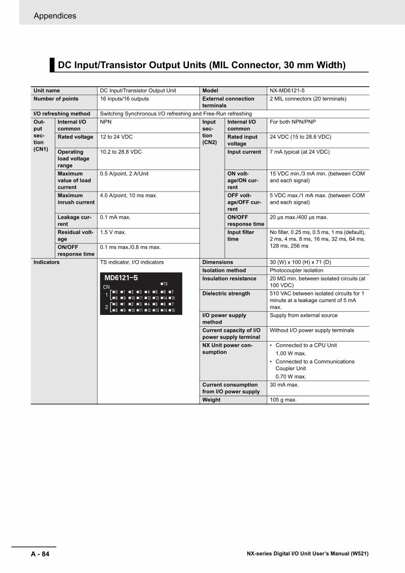
Appendices
A - 84 NX-series Digital I/O Unit User’s Manual (W521)
DC Input/Transistor Output Units (MIL Connector, 30 mm Width)
Unit name DC Input/Transistor Output Unit Model NX-MD6121-5Number of points 16 inputs/16 outputs External connection
terminals2 MIL connectors (20 terminals)
I/O refreshing method Switching Synchronous I/O refreshing and Free-Run refreshingOut-put sec-tion (CN1)
Internal I/O common
NPN Input sec-tion (CN2)
Internal I/O common
For both NPN/PNP
Rated voltage 12 to 24 VDC Rated input voltage
24 VDC (15 to 28.8 VDC)
Operating load voltage range
10.2 to 28.8 VDC Input current 7 mA typical (at 24 VDC)
Maximum value of load current
0.5 A/point, 2 A/Unit ON volt-age/ON cur-rent
15 VDC min./3 mA min. (between COM and each signal)
Maximum inrush current
4.0 A/point, 10 ms max. OFF volt-age/OFF cur-rent
5 VDC max./1 mA max. (between COM and each signal)
Leakage cur-rent
0.1 mA max. ON/OFF response time
20 μs max./400 μs max.
Residual volt-age
1.5 V max. Input filter time
No filter, 0.25 ms, 0.5 ms, 1 ms (default), 2 ms, 4 ms, 8 ms, 16 ms, 32 ms, 64 ms, 128 ms, 256 msON/OFF
response time0.1 ms max./0.8 ms max.
Indicators TS indicator, I/O indicators Dimensions 30 (W) x 100 (H) x 71 (D)Isolation method Photocoupler isolationInsulation resistance 20 MΩ min. between isolated circuits (at
100 VDC)Dielectric strength 510 VAC between isolated circuits for 1
minute at a leakage current of 5 mA max.
I/O power supply method
Supply from external source
Current capacity of I/O power supply terminal
Without I/O power supply terminals
NX Unit power con-sumption
• Connected to a CPU Unit1.00 W max.
• Connected to a Communications Coupler Unit0.70 W max.
Current consumption from I/O power supply
30 mA max.
Weight 105 g max.

A - 85
Appendices
NX-series Digital I/O Unit User’s Manual (W521)
A-1 D
ata Sheet
A
A-1-4 D
igital Mixed I/O
Units
Circuit layout
OUT0 to OUT15
COM0
+V0
CN1 (left) output circuit
+V0
COM0
IN0to
IN15
COM1COM1
Input indicator
3.3 kΩ
CN2 (right) input circuit
I/O power supply +NX bus
connector(left) I/O power
supply −
NX busconnector(right)
I/O power supply +I/O power supply −
Inte
rnal
circ
uits
Inte
rnal
circ
uits
Connector
Connector
I/O power supply +NX bus
connector(left) I/O power
supply −
NX busconnector(right)
I/O power supply +I/O power supply −

Appendices
A - 86 NX-series Digital I/O Unit User’s Manual (W521)
Installation orientation and restrictions
Installation orientation:• Connected to a CPU Unit
Possible in upright installation.• Connected to a Communications Coupler Unit
Possible in 6 orientations.
Restrictions: As shown in the following.
6050403020100
16
8
4
0
12
5545
06050403020100 5545
16
8
4
12
I/O power supply voltage24 V28.8 V
I/O power supply voltage
24 V28.8 V
• For any installation other than upright
Number of simultaneously ON input points vs. Ambient temperature characteristic
• For upright installationNumber of simultaneously ON input points vs. Ambient temperature characteristic
Num
ber o
f sim
ulta
neou
sly
ON
inpu
t poi
nts
Num
ber o
f sim
ulta
neou
sly
ON
inpu
t poi
nts
16 points at 35°C 16 points at 45°C
13 points at 55°C
9 points at 55°C
16 points at 40°C16 points at 25°C
5 points at 55°C
3 points at 55°C
Ambient temperature
Ambient temperature
(°C)
(°C)

A - 87
Appendices
NX-series Digital I/O Unit User’s Manual (W521)
A-1 D
ata Sheet
A
A-1-4 D
igital Mixed I/O
Units
Terminal connection diagram
Disconnec-tion/Short-circuit detection
Not supported. Protective function Not supported.
20
16
12
18
14
10
642
8
OUT0
OUT2
OUT4
OUT1
OUT3
OUT5
OUT7COM0
+V0
OUT6
19
15
11
17
13
9
531
7
12 to 24 VDC
OUT8
OUT10
OUT12
OUT9
OUT11
OUT13
OUT15COM0+V0
OUT14
LLLLLLLL
LLLLLLLL
CN1 (left) output terminal
• Be sure to wire both pins 3 and 4 (COM0) of CN1.• Be sure to wire both pins 1 and 2 (+V0) of CN1.
• The polarity of the input power supply of CN2 can be connected in either direction.• Be sure to wire both pins 3 and 4 (COM1) of CN2, and set the same polarity for both pins.
1
5
9
3
7
11
151719
13
NC
IN15
IN13
COM1
IN14
IN12
IN10IN09IN08
IN11
2
6
10
4
8
12
161820
14
NC
IN07
IN05
COM1
IN06
IN04
IN02IN01IN00
IN03
24 VDC
CN2 (right) input terminal
Connectorpin
Signalname
Signalname
Connectorpin
Signalname
Signalname

Appendices
A - 88 NX-series Digital I/O Unit User’s Manual (W521)
Unit name DC Input/Transistor Output Unit Model NX-MD6256-5Number of points 16 inputs/16 outputs External connection
terminals2 MIL connectors (20 terminals)
I/O refreshing method Switching Synchronous I/O refreshing and Free-Run refreshingOut-put sec-tion (CN1)
Internal I/O common
PNP Input sec-tion (CN2)
Internal I/O common
For both NPN/PNP
Rated voltage 24 VDC Rated input voltage
24 VDC (15 to 28.8 VDC)
Operating load voltage range
20.4 to 28.8 VDC Input current 7 mA typical (at 24 VDC)
Maximum value of load current
0.5 A/point, 2 A/Unit ON volt-age/ON cur-rent
15 VDC min./3 mA min. (between COM and each signal)
Maximum inrush current
4.0 A/point, 10 ms max. OFF volt-age/OFF cur-rent
5 VDC max./1 mA max. (between COM and each signal)
Leakage cur-rent
0.1 mA max. ON/OFF response time
20 μs max./400 μs max.
Residual volt-age
1.5 V max. Input filter time
No filter, 0.25 ms, 0.5 ms, 1 ms (default), 2 ms, 4 ms, 8 ms, 16 ms, 32 ms, 64 ms, 128 ms, 256 msON/OFF
response time0.5 ms max./1.0 ms max.
Indicators TS indicator, I/O indicators Dimensions 30 (W) x 100 (H) x 71 (D)Isolation method Photocoupler isolationInsulation resistance 20 MΩ min. between isolated circuits (at
100 VDC)Dielectric strength 510 VAC between isolated circuits for 1
minute at a leakage current of 5 mA max.
I/O power supply method
Supply from external source
Current capacity of I/O power supply terminal
Without I/O power supply terminals
NX Unit power con-sumption
• Connected to a CPU Unit1.10 W max.
• Connected to a Communications Coupler Unit0.75 W max.
Current consumption from I/O power supply
40 mA max.
Weight 110 g max.

A - 89
Appendices
NX-series Digital I/O Unit User’s Manual (W521)
A-1 D
ata Sheet
A
A-1-4 D
igital Mixed I/O
Units
Circuit layout
OUT0 to OUT150V00V0
COM0 (+V)COM0 (+V)
Connector
Inte
rnal
circ
uits
Shor
t-circ
uit
prot
ectio
n
Connector
Inte
rnal
circ
uitsIN0
toIN15
COM1COM1
Input indicator3.3 kΩ
CN1 (left) output circuit
CN2 (right) input circuit
I/O power supply +NX bus
connector(left) I/O power
supply −
NX busconnector(right)
I/O power supply +I/O power supply −
I/O power supply +NX bus
connector(left) I/O power
supply −
NX busconnector(right)
I/O power supply +I/O power supply −

Appendices
A - 90 NX-series Digital I/O Unit User’s Manual (W521)
Installation orientation and restrictions
Installation orientation:• Connected to a CPU Unit
Possible in upright installation.• Connected to a Communications Coupler Unit
Possible in 6 orientations.
Restrictions: As shown in the following.
6050403020100
16
8
4
0
12
5545
06050403020100 5545
16
8
4
12
I/O power supply voltage24 V28.8 V
I/O power supply voltage
24 V28.8 V
• For any installation other than upright
Number of simultaneously ON input points vs. Ambient temperature characteristic
• For upright installation
Number of simultaneously ON input points vs. Ambient temperature characteristic
Num
ber o
f sim
ulta
neou
sly
ON
inpu
t poi
nts
Num
ber o
f sim
ulta
neou
sly
ON
inpu
t poi
nts
16 points at 35°C 16 points at 45°C
13 points at 55°C
9 points at 55°C
16 points at 40°C16 points at 25°C
5 points at 55°C
3 points at 55°C
Ambient temperature
Ambient temperature
(°C)
(°C)

A - 91
Appendices
NX-series Digital I/O Unit User’s Manual (W521)
A-1 D
ata Sheet
A
A-1-4 D
igital Mixed I/O
Units
Terminal connection diagram
Disconnec-tion/Short-circuit detection
Not supported. Protective function With load short-circuit protection.
20
16
12
18
14
10
642
8
OUT0
OUT2
OUT4
OUT1
OUT3
OUT5
OUT7COM0 (+V)
0V0
OUT6
19
15
11
17
13
9
531
7
24 VDC
OUT8
OUT10
OUT12
OUT9
OUT11
OUT13
OUT15COM0 (+V)0V0
OUT14
• Be sure to wire both pins 3 and 4 (COM0 (+V)) of CN1.• Be sure to wire both pins 1 and 2 (0V0) of CN1.
24 VDC
CN2 (right) input terminal
Connectorpin
Signalname
Signalname
1
5
9
3
7
11
151719
13
NC
IN15
IN13
COM1
IN14
IN12
IN10IN09IN08
IN11
2
6
10
4
8
12
161820
14
NC
IN07
IN05
COM1
IN06
IN04
IN02IN01IN00
IN03
CN1 (left) output terminalConnector
pinSignalname
Signalname
LLLLLLLL
LLLLLLLL
• The polarity of the input power supply of CN2 can be connected in either direction.• Be sure to wire both pins 3 and 4 (COM1) of CN2, and set the same polarity for both pins.

Appendices
A - 92 NX-series Digital I/O Unit User’s Manual (W521)
DC Input/Transistor Output Units (Fujitsu Connector, 30 mm Width)
Unit name DC Input/Transistor Output Unit Model NX-MD6121-6Number of points 16 inputs/16 outputs External connection
terminals2 Fujitsu connectors (24 terminals)
I/O refreshing method Switching Synchronous I/O refreshing and Free-Run refreshingOut-put sec-tion (CN1)
Internal I/O common
NPN Input sec-tion (CN2)
Internal I/O common
For both NPN/PNP
Rated voltage 12 to 24 VDC Rated input voltage
24 VDC (15 to 28.8 VDC)
Operating load voltage range
10.2 to 28.8 VDC Input current 7 mA typical (at 24 VDC)
Maximum value of load current
0.5 A/point, 2 A/Unit ON volt-age/ON cur-rent
15 VDC min./3 mA min. (between COM and each signal)
Maximum inrush current
4.0 A/point, 10 ms max. OFF volt-age/OFF cur-rent
5 VDC max./1 mA max. (between COM and each signal)
Leakage cur-rent
0.1 mA max. ON/OFF response time
20 μs max./400 μs max.
Residual volt-age
1.5 V max. Input filter time
No filter, 0.25 ms, 0.5 ms, 1 ms (default), 2 ms, 4 ms, 8 ms, 16 ms, 32 ms, 64 ms, 128 ms, 256 msON/OFF
response time0.1 ms max./0.8 ms max.
Indicators TS indicator, I/O indicators Dimensions 30 (W) x 100 (H) x 71 (D)Isolation method Photocoupler isolationInsulation resistance 20 MΩ min. between isolated circuits (at
100 VDC)Dielectric strength 510 VAC between isolated circuits for 1
minute at a leakage current of 5 mA max.
I/O power supply method
Supply from external source
Current capacity of I/O power supply terminal
Without I/O power supply terminals
NX Unit power con-sumption
• Connected to a CPU Unit1.00 W max.
• Connected to a Communications Coupler Unit0.70 W max.
Current consumption from I/O power supply
30 mA max.
Weight 95 g max.

A - 93
Appendices
NX-series Digital I/O Unit User’s Manual (W521)
A-1 D
ata Sheet
A
A-1-4 D
igital Mixed I/O
Units
Circuit layout
OUT0 to OUT15
COM0
+V0
CN1 (left) output circuit
+V0
COM0
IN0to
IN15
COM1COM1
Input indicator
3.3 kΩ
CN2 (right) input circuit
I/O power supply +NX bus
connector(left) I/O power
supply −
NX busconnector(right)
I/O power supply +I/O power supply −
Inte
rnal
circ
uits
Inte
rnal
circ
uits
Connector
Connector
I/O power supply +NX bus
connector(left) I/O power
supply −
NX busconnector(right)
I/O power supply +I/O power supply −

Appendices
A - 94 NX-series Digital I/O Unit User’s Manual (W521)
Installation orientation and restrictions
Installation orientation:• Connected to a CPU Unit
Possible in upright installation.• Connected to a Communications Coupler Unit
Possible in 6 orientations.
Restrictions: As shown in the following.
6050403020100
16
8
4
0
12
5545
06050403020100 5545
16
8
4
12
I/O power supply voltage24 V28.8 V
I/O power supply voltage
24 V28.8 V
• For any installation other than upright
Number of simultaneously ON input points vs. Ambient temperature characteristic
• For upright installationNumber of simultaneously ON input points vs. Ambient temperature characteristic
Num
ber o
f sim
ulta
neou
sly
ON
inpu
t poi
nts
Num
ber o
f sim
ulta
neou
sly
ON
inpu
t poi
nts
16 points at 35°C 16 points at 45°C
13 points at 55°C
9 points at 55°C
16 points at 40°C16 points at 25°C
5 points at 55°C
3 points at 55°C
Ambient temperature
Ambient temperature
(°C)
(°C)

A - 95
Appendices
NX-series Digital I/O Unit User’s Manual (W521)
A-1 D
ata Sheet
A
A-1-4 D
igital Mixed I/O
Units
Terminal connection diagram
Disconnec-tion/Short-circuit detection
Not supported. Protective function Not supported.
+V0NCNC
OUT15
OUT13
COM0
OUT14
OUT12
OUT10OUT9OUT8
OUT11
B10
B8
B6
B9
B7
B5
B3B2B1
B4
A10B11 A11B12 A12
B A
A8
A6
A9
A7
A5
A3A2A1
A4
Connectorpin Signal nameSignal name
Connectorpin Signal nameSignal name
A3
A5
A7
A4
A6
A8
A10A11A12
A9
B3A2 B2A1 B1A B
B5
B7
B4
B6
B8
B10B11B12
B9
12 to 24 VDC
+V0NCNC
OUT7
OUT5
COM0
OUT6
OUT4
OUT2OUT1OUT0
OUT3
LLLLLLLL
LLLLLLLL
• Be sure to wire both pins A9 and B9 (COM0) of CN1.• Be sure to wire both pins A10 and B10 (+V0) of CN1.
CN1 (left) output terminal
IN0
IN2
IN4
IN1
IN3
IN5
IN7COM1
NCNCNC
IN6
IN8
IN10
IN12
IN9
IN11
IN13
IN15COM1NCNCNC
IN14
24 VDC
• The polarity of the input power supply of CN2 can be connected in either direction.• Be sure to wire both pins A9 and B9 (COM1) of CN2, and set the same polarity for both pins.
CN2 (right) input terminal

Appendices
A - 96 NX-series Digital I/O Unit User’s Manual (W521)
A-2 Dimensions
*1. The dimension is 1.35 mm for Units with lot numbers through December 2014.
A-2-1 Screwless Clamping Terminal Block Type
12 mm Width
24 mm Width
80.171
104.
5
100
14.1
65.2
12.0
(Unit: mm)
1.5
1.5
0.55*1
26.124.0
C D
C D
(Unit: mm)80.171
104.
5
100
65.21.5
1.5
0.55

A - 97
Appendices
NX-series Digital I/O Unit User’s Manual (W521)
A-2 D
imensions
A
A-2-1 S
crewless C
lamping Term
inal Block Type
Installation Height
100
71
(Unit: mm)

Appendices
A - 98 NX-series Digital I/O Unit User’s Manual (W521)
A-2-2 M3 Screw Terminal Block Type
30 mm Width
(Unit: mm)
30
32.1
71
95
1.5
100
1.5
65.2
104.
5
16.1

A - 99
Appendices
NX-series Digital I/O Unit User’s Manual (W521)
A-2 D
imensions
A
A-2-3 C
onnector Types
Units with MIL Connectors (1 Connector with 20 Terminals)
Units with MIL Connectors (1 Connector with 40 Terminals)
A-2-3 Connector Types
30 mm Width
32.1
100
1.5
1.5
27.8
5
19.1
16.1
30 7165.2
89.52
104.
5
58.3
(Unit: mm)
38
32.1
19.1
16.1
30 7165.2
89.52
104.
5
83.710
01.
51.
5
(Unit: mm)

Appendices
A - 100 NX-series Digital I/O Unit User’s Manual (W521)
Units with MIL Connectors (2 Connectors with 20 Terminals)
Units with Fujitsu Connectors (1 Connector with 40 Terminals)
32.1
19.18.9
16.1
30 7165.2
89.52
104.
5
58.3
100
1.5
1.5
27.8
5
(Unit: mm)
(Unit:mm)
1.5
100
1.5
72.5
(118.5)
71
65.2
104.
5
16.1
32.1
19.4
30
38
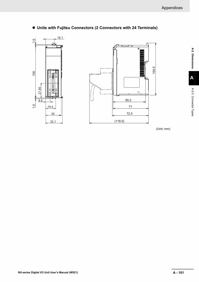
A - 101
Appendices
NX-series Digital I/O Unit User’s Manual (W521)
A-2 D
imensions
A
A-2-3 C
onnector Types
Units with Fujitsu Connectors (2 Connectors with 24 Terminals)
(Unit: mm)
100
1.5
1.5
72.5
(118.5)
71
65.2
104.
5
16.127
.85
32.1
19.4
8.6
30

Appendices
A - 102 NX-series Digital I/O Unit User’s Manual (W521)
A-3 Connecting Connector-Terminal Block Conversion Units and I/O Relay Terminals
The following patterns can be used to connect Digital I/O Units with connectors to OMRON Connec-tor-Terminal Block Conversion Units and I/O Relay Terminals using OMRON Connecting Cables.
A-3-1 Patterns for Combining Connector-Terminal Block ConversionUnits and I/O Relay Terminals
Connection Patterns for Connector-Terminal Block Conversion Units
Pattern Configuration Number of connectors Branching
A
1
None
B 2 branches
C 2 None
Connector-Terminal Block Conversion Unit
20 or 40 terminals
Connecting Cable
20 terminals 20 terminals
Connector-Terminal Block Conversion Unit
Connecting Cable with two branches
Connector-Terminal Block Conversion Unit
Connecting Cable
20 terminals20 terminals

A - 103
Appendices
NX-series Digital I/O Unit User’s Manual (W521)
A-3 C
onnecting Connector-Term
inal Block
Conversion U
nits and I/O R
elay Terminals
A
A-3-1 P
atterns for Com
bining Connector-Term
inal Block C
onversion Units and I/O
Relay Term
inals
Connection Patterns for I/O Relay Terminals
Pattern Configuration
A
E
F
I/O Relay Terminal
Connecting Cable
Connecting Cable
I/O Relay TerminalI/O Relay Terminal
I/O Relay Terminal
Connecting Cable
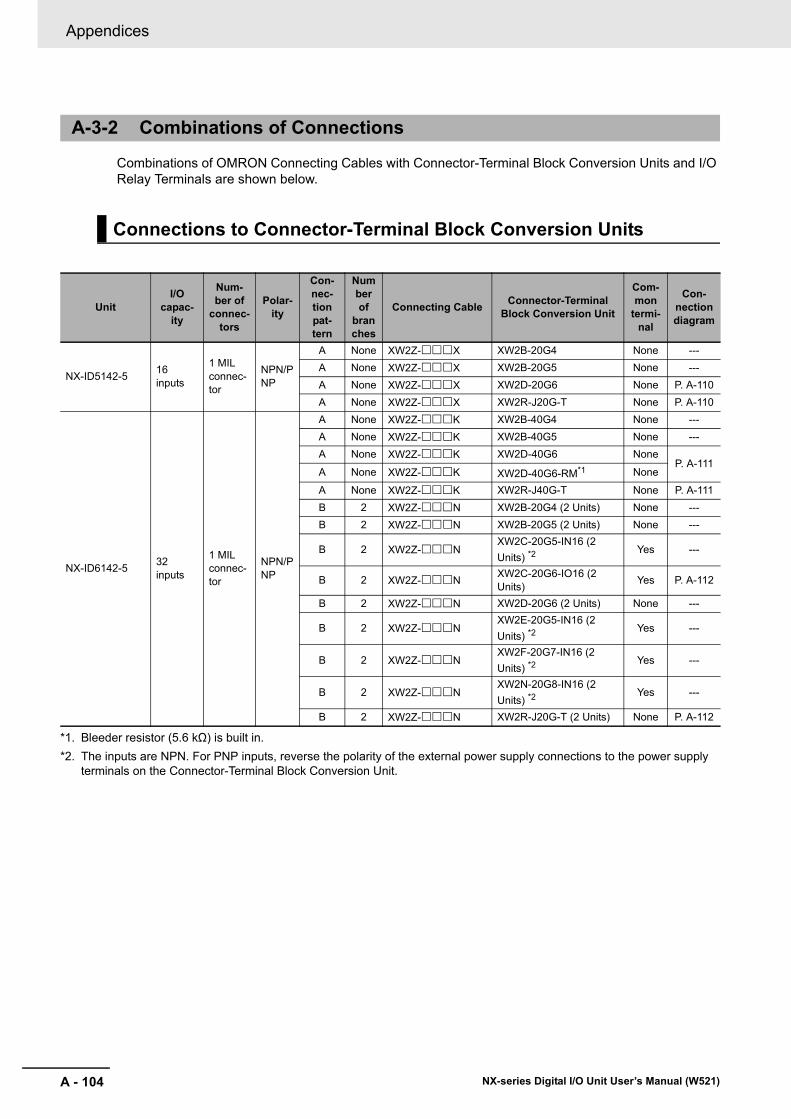
Appendices
A - 104 NX-series Digital I/O Unit User’s Manual (W521)
Combinations of OMRON Connecting Cables with Connector-Terminal Block Conversion Units and I/O Relay Terminals are shown below.
A-3-2 Combinations of Connections
Connections to Connector-Terminal Block Conversion Units
UnitI/O
capac-ity
Num-ber of
connec-tors
Polar-ity
Con-nec-tion pat-tern
Number of
branches
Connecting Cable Connector-Terminal Block Conversion Unit
Com-mon
termi-nal
Con-nection diagram
NX-ID5142-5 16 inputs
1 MIL connec-tor
NPN/PNP
A None XW2Z-X XW2B-20G4 None ---A None XW2Z-X XW2B-20G5 None ---A None XW2Z-X XW2D-20G6 None P. A-110A None XW2Z-X XW2R-J20G-T None P. A-110
NX-ID6142-5 32 inputs
1 MIL connec-tor
NPN/PNP
A None XW2Z-K XW2B-40G4 None ---A None XW2Z-K XW2B-40G5 None ---A None XW2Z-K XW2D-40G6 None
P. A-111A None XW2Z-K XW2D-40G6-RM*1
*1. Bleeder resistor (5.6 kΩ) is built in.
None
A None XW2Z-K XW2R-J40G-T None P. A-111B 2 XW2Z-N XW2B-20G4 (2 Units) None ---B 2 XW2Z-N XW2B-20G5 (2 Units) None ---
B 2 XW2Z-NXW2C-20G5-IN16 (2 Units) *2
*2. The inputs are NPN. For PNP inputs, reverse the polarity of the external power supply connections to the power supply terminals on the Connector-Terminal Block Conversion Unit.
Yes ---
B 2 XW2Z-N XW2C-20G6-IO16 (2 Units) Yes P. A-112
B 2 XW2Z-N XW2D-20G6 (2 Units) None ---
B 2 XW2Z-NXW2E-20G5-IN16 (2 Units) *2
Yes ---
B 2 XW2Z-NXW2F-20G7-IN16 (2 Units) *2
Yes ---
B 2 XW2Z-NXW2N-20G8-IN16 (2 Units) *2
Yes ---
B 2 XW2Z-N XW2R-J20G-T (2 Units) None P. A-112

A - 105
Appendices
NX-series Digital I/O Unit User’s Manual (W521)
A-3 C
onnecting Connector-Term
inal Block
Conversion U
nits and I/O R
elay Terminals
A
A-3-2 C
ombinations of C
onnections
UnitI/O
capac-ity
Num-ber of
connec-tors
Polar-ity
Con-nec-tion pat-tern
Number of
branches
Connecting Cable Connector-Terminal Block Conversion Unit
Com-mon
termi-nal
Con-nection diagram
NX-ID6142-6 32 inputs
1 Fujitsu connec-tor
NPN/PNP
A None XW2Z-B XW2B-40G4 None ---A None XW2Z-B XW2B-40G5 None ---A None XW2Z-B XW2D-40G6 None
P. A-113A None XW2Z-B XW2D-40G6-RF*1
*1. Bleeder resistor (5.6 kΩ) is built in.
None
A None XW2Z-B XW2R-J40G-T None P. A-113A None XW2Z-BU XW2D-40C6 None ---B 2 XW2Z-D XW2B-20G4 (2 Units) None ---B 2 XW2Z-D XW2B-20G5 (2 Units) None ---
B 2 XW2Z-DXW2C-20G5-IN16 (2 Units) *2
*2. The inputs are NPN. For PNP inputs, reverse the polarity of the external power supply connections to the power supply terminals on the Connector-Terminal Block Conversion Unit.
Yes ---
B 2 XW2Z-D XW2C-20G6-IO16 (2 Units) Yes P. A-114
B 2 XW2Z-D XW2D-20G6 (2 Units) None ---
B 2 XW2Z-DXW2E-20G5-IN16 (2 Units) *2
Yes ---
B 2 XW2Z-DXW2F-20G7-IN16 (2 Units) *2
Yes ---
B 2 XW2Z-DXW2N-20G8-IN16 (2 Units) *2
Yes ---
B 2 XW2Z-D XW2R-J20G-T (2 Units) None P. A-114

Appendices
A - 106 NX-series Digital I/O Unit User’s Manual (W521)
UnitI/O
capac-ity
Num-ber of
connec-tors
Polar-ity
Con-nec-tion pat-tern
Number of
branches
Connecting Cable Connector-Terminal Block Conversion Unit
Com-mon
termi-nal
Con-nection diagram
NX-OD5121-5 16 out-puts
1 MIL connec-tor
NPN
A None XW2Z-X XW2B-20G4 None ---A None XW2Z-X XW2B-20G5 None ---A None XW2Z-X XW2D-20G6 None P. A-115A None XW2Z-X XW2R-J20G-T None P. A-115
NX-OD5256-5 16 out-puts
1 MIL connec-tor
PNP
A None XW2Z-X XW2B-20G4 None ---A None XW2Z-X XW2B-20G5 None ---A None XW2Z-X XW2D-20G6 None P. A-116A None XW2Z-X XW2R-J20G-T None P. A-116
NX-OD6121-5 32 out-puts
1 MIL connec-tor
NPN
A None XW2Z-K XW2B-40G4 None ---A None XW2Z-K XW2B-40G5 None ---A None XW2Z-K XW2D-40G6 None P. A-117A None XW2Z-K XW2R-J40G-T None P. A-117B 2 XW2Z-N XW2B-20G4 (2 Units) None ---B 2 XW2Z-N XW2B-20G5 (2 Units) None ---
B 2 XW2Z-N XW2C-20G6-IO16 (2 Units) Yes P. A-118
B 2 XW2Z-N XW2D-20G6 (2 Units) None ---
B 2 XW2Z-N XW2F-20G7-OUT16 (2 Units) Yes ---
B 2 XW2Z-N XW2R-J20G-T (2 Units) None P. A-118
NX-OD6121-6 32 out-puts
1 Fujitsu connec-tor
NPN
A None XW2Z-B XW2B-40G4 None ---A None XW2Z-B XW2B-40G5 None ---A None XW2Z-B XW2D-40G6 None P. A-119A None XW2Z-B XW2R-J40G-T None P. A-119A None XW2Z-BU XW2D-40C6 None ---B 2 XW2Z-L XW2B-20G4 (2 Units) None ---B 2 XW2Z-L XW2B-20G5 (2 Units) None ---
B 2 XW2Z-L XW2C-20G6-IO16 (2 Units) Yes P. A-120
B 2 XW2Z-L XW2D-20G6 (2 Units) None ---
B 2 XW2Z-L XW2F-20G7-OUT16 (2 Units) Yes ---
B 2 XW2Z-L XW2R-J20G-T (2 Units) None P. A-120
NX-OD6256-5 32 out-puts
1 MIL connec-tor
PNP
A None XW2Z-K XW2B-40G4 None ---A None XW2Z-K XW2B-40G5 None ---A None XW2Z-K XW2D-40G6 None P. A-121A None XW2Z-K XW2R-J40G-T None P. A-121B 2 XW2Z-N XW2B-20G4 (2 Units) None ---B 2 XW2Z-N XW2B-20G5 (2 Units) None ---
B 2 XW2Z-N XW2C-20G6-IO16 (2 Units) Yes P. A-122
B 2 XW2Z-N XW2D-20G6 (2 Units) None ---
B 2 XW2Z-N XW2F-20G7-OUT16 (2 Units) Yes ---
B 2 XW2Z-N XW2R-J20G-T (2 Units) None P. A-122
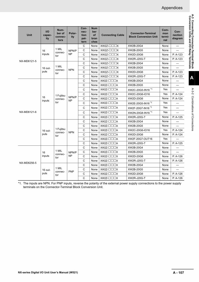
A - 107
Appendices
NX-series Digital I/O Unit User’s Manual (W521)
A-3 C
onnecting Connector-Term
inal Block
Conversion U
nits and I/O R
elay Terminals
A
A-3-2 C
ombinations of C
onnections
NX-MD6121-5
16 inputs
1 MIL connec-tor
NPN/PNP
C None XW2Z-X XW2B-20G4 None ---C None XW2Z-X XW2B-20G5 None ---C None XW2Z-X XW2D-20G6 None P. A-123C None XW2Z-X XW2R-J20G-T None P. A-123
16 out-puts
1 MIL connec-tor
NPN
C None XW2Z-X XW2B-20G4 None ---C None XW2Z-X XW2B-20G5 None ---C None XW2Z-X XW2D-20G6 None P. A-123C None XW2Z-X XW2R-J20G-T None P. A-123
NX-MD6121-6
16 inputs
1 Fujitsu connec-tor
NPN/PNP
C None XW2Z-A XW2B-20G4 None ---C None XW2Z-A XW2B-20G5 None ---
C None XW2Z-A XW2C-20G5-IN16 *1 Yes ---
C None XW2Z-A XW2C-20G6-IO16 Yes P. A-124C None XW2Z-A XW2D-20G6 None P. A-124
C None XW2Z-A XW2E-20G5-IN16 *1 Yes ---
C None XW2Z-A XW2F-20G7-IN16 *1 Yes ---
C None XW2Z-A XW2N-20G8-IN16 *1 Yes ---
C None XW2Z-A XW2R-J20G-T None P. A-125
16 out-puts
1 Fujitsu connec-tor
NPN
C None XW2Z-A XW2B-20G4 None ---C None XW2Z-A XW2B-20G5 None ---C None XW2Z-A XW2C-20G6-IO16 Yes P. A-124C None XW2Z-A XW2D-20G6 None P. A-124C None XW2Z-A XW2F-20G7-OUT16 Yes ---C None XW2Z-A XW2R-J20G-T None P. A-125
NX-MD6256-5
16 inputs
1 MIL connec-tor
NPN/PNP
C None XW2Z-X XW2B-20G4 None ---C None XW2Z-X XW2B-20G5 None ---C None XW2Z-X XW2D-20G6 None P. A-126C None XW2Z-X XW2R-J20G-T None P. A-126
16 out-puts
1 MIL connec-tor
PNP
C None XW2Z-X XW2B-20G4 None ---C None XW2Z-X XW2B-20G5 None ---C None XW2Z-X XW2D-20G6 None P. A-126C None XW2Z-X XW2R-J20G-T None P. A-126
*1. The inputs are NPN. For PNP inputs, reverse the polarity of the external power supply connections to the power supply terminals on the Connector-Terminal Block Conversion Unit.
UnitI/O
capac-ity
Num-ber of
connec-tors
Polar-ity
Con-nec-tion pat-tern
Number of
branches
Connecting Cable Connector-Terminal Block Conversion Unit
Com-mon
termi-nal
Con-nection diagram

Appendices
A - 108 NX-series Digital I/O Unit User’s Manual (W521)
Connections to I/O Relay Terminals
Unit I/O capacity
Number of connec-
tors
Polar-ity
Connec-tion pat-
tern
Number of
branchesConnecting Cable I/O Relay Terminal
Con-nection diagram
NX-ID5142-5 16 inputs 1 MIL con-nector NPN
F None XW2Z-ROC G7TC-ID16
P. A-127
F None XW2Z-ROC G7TC-IA16
NX-ID6142-5 32 inputs 1 MIL con-nector NPN
A 2 XW2Z-RO--D1 G7TC-ID16A 2 XW2Z-RO--D1 G7TC-IA16
NX-ID6142-6 32 inputs 1 Fujitsu connector NPN
A 2 XW2Z-RIC- G7TC-ID16A 2 XW2Z-RIC- G7TC-IA16
NX-OD5121-5 16 out-puts
1 MIL con-nector NPN
F None XW2Z-ROC G7TC-OC08 P. A-131F None XW2Z-ROC G70D-SOC08 P. A-129F None XW2Z-ROC G70R-SOC08 P. A-130F None XW2Z-ROC G7TC-OC16 P. A-131F None XW2Z-ROC G70D-SOC16 P. A-129F None XW2Z-ROC G70D-VSOC16 P. A-128F None XW2Z-ROC G70D-FOM16 ---F None XW2Z-ROC G70D-VFOM16 ---F None XW2Z-ROC G70A-ZOC16-3 ---
NX-OD5256-5 16 out-puts
1 MIL con-nector PNP
F None XW2Z-RIC G7TC-OC16-1 P. A-131F None XW2Z-ROC G70D-SOC16-1 P. A-130F None XW2Z-ROC G70D-FOM16-1 ---F None XW2Z-ROC G70A-ZOC16-4 ---
NX-OD6121-5 32 out-puts
1 MIL con-nector NPN
A 2 XW2Z-RO--D1 G7TC-OC16P. A-131
A 2 XW2Z-RO--D1 G7TC-OC08A 2 XW2Z-RO--D1 G70D-SOC16 P. A-129A 2 XW2Z-RO--D1 G70D-FOM16 ---A 2 XW2Z-RO--D1 G70D-VSOC16 P. A-128A 2 XW2Z-RO--D1 G70D-VFOM16 ---
A 2 XW2Z-RO--D1 G70A-ZOC16-3 and Relay P. A-132
A 2 XW2Z-RO--D1 G70R-SOC08 P. A-130A 2 XW2Z-RO--D1 G70D-SOC08 P. A-129
NX-OD6121-6 32 out-puts
1 Fujitsu connector NPN
A 2 XW2Z-ROC- G7TC-OC16P. A-131
A 2 XW2Z-ROC- G7TC-OC08A 2 XW2Z-ROC- G70D-SOC16 P. A-129A 2 XW2Z-ROC- G70D-FOM16 ---A 2 XW2Z-ROC- G70D-VSOC16 P. A-128A 2 XW2Z-ROC- G70D-VFOM16 ---
A 2 XW2Z-ROC- G70A-ZOC16-3 and Relay P. A-132
A 2 XW2Z-ROC- G70R-SOC08 P. A-130A 2 XW2Z-ROC- G70D-SOC08 P. A-129
NX-OD6256-5 32 out-puts
1 MIL con-nector PNP
A 2 XW2Z-RI--D1 G7TC-OC16-1 P. A-131A 2 XW2Z-RO--D1 G70D-SOC16-1 P. A-130A 2 XW2Z-RO--D1 G70D-FOM16-1 ---
A 2 XW2Z-RO--D1 G70A-ZOC16-4 and Relay ---

A - 109
Appendices
NX-series Digital I/O Unit User’s Manual (W521)
A-3 C
onnecting Connector-Term
inal Block
Conversion U
nits and I/O R
elay Terminals
A
A-3-2 C
ombinations of C
onnections
NX-MD6121-5
16 inputs 1 MIL con-nector NPN
E None XW2Z-ROC G7TC-ID16P. A-127
E None XW2Z-ROC G7TC-IA16
16 out-puts
1 MIL con-nector NPN
E None XW2Z-ROC G7TC-OC16P. A-131
E None XW2Z-ROC G7TC-OC08E None XW2Z-ROC G70D-SOC16 P. A-129E None XW2Z-ROC G70D-FOM16 ---E None XW2Z-ROC G70D-VSOC16 P. A-128E None XW2Z-ROC G70D-VFOM16 ---
E None XW2Z-ROC G70A-ZOC16-3 and Relay P. A-132
E None XW2Z-ROC G70R-SOC08 P. A-130E None XW2Z-ROC G70D-SOC08 P. A-129
NX-MD6121-6
16 inputs 1 Fujitsu connector NPN
E None XW2Z-RC G7TC-ID16P. A-127
E None XW2Z-RC G7TC-IA16
16 out-puts
1 Fujitsu connector NPN
E None XW2Z-RC G7TC-OC16P. A-131
E None XW2Z-RC G7TC-OC08E None XW2Z-RC G70D-SOC16 P. A-129E None XW2Z-RC G70D-FOM16 ---E None XW2Z-RC G70D-VSOC16 P. A-128E None XW2Z-RC G70D-VFOM16 ---
E None XW2Z-RC G70A-ZOC16-3 and Relay P. A-132
E None XW2Z-RC G70R-SOC08 P. A-130E None XW2Z-RC G70D-SOC08 P. A-129
NX-MD6256-5 16 out-puts
1 MIL con-nector PNP
E None XW2Z-ROC G7TC-OC16-1 P. A-131E None XW2Z-RIC G70D-SOC16-1 P. A-130E None XW2Z-RIC G70D-FOM16-1 ---E None XW2Z-RIC G70A-ZOC16-4 and
Relay ---
Unit I/O capacity
Number of connec-
tors
Polar-ity
Connec-tion pat-
tern
Number of
branchesConnecting Cable I/O Relay Terminal
Con-nection diagram

Appendices
A - 110 NX-series Digital I/O Unit User’s Manual (W521)
The applicable terminals on the Connector-Terminal Block Conversion Unit and external connection diagrams are provided below for Digital I/O Unit connections to Connector-Terminal Block Conversion Units.
In the connection diagrams here, 1 word consists of 16 points of the I/O terminals and the first word is called Wd m.
Note 1. The polarity for input power supply connections indicated with dotted lines (- - - - -) can be con-nected in either direction.
2. The COM terminals are internally connected inside the Unit, but they must all be wired.
Note 1. The polarity for input power supply connections indicated with dotted lines (- - - - -) can be con-nected in either direction.
2. The COM terminals are internally connected inside the Unit, but they must all be wired.
A-3-3 Connector-Terminal Block Conversion Unit Connection Diagrams
Inputs
Digital I/O Unit NX-ID5142-5
Connec-tor-Terminal Block Con-version Unit
XW2D-20G6
Connecting Cable XW2Z-X
Connection diagram
A10
A1
A2
A3
A4
A5
A6
A7
A8
A9
B10
B1
B2
B3
B4
B5
B6
B7
B8
B909
08
NC
10
11
12
13
14
15
COM
01
00
NC
02
03
04
05
06
07
COM
24VDC
Digital I/O Unit NX-ID5142-5
Connec-tor-Terminal Block Con-version Unit
XW2R-J20G-T
Connecting Cable XW2Z-X
Connection diagram
A10
A1
A2
A3
A4
A5
A6
A7
A8
A9
B10
B1
B2
B3
B4
B5
B6
B7
B8
B9 09
08
NC
10
11
12
13
14
15
COM
01
00
NC
02
03
04
05
06
07
COM
24VDC

A - 111
Appendices
NX-series Digital I/O Unit User’s Manual (W521)
A-3 C
onnecting Connector-Term
inal Block
Conversion U
nits and I/O R
elay Terminals
A
A-3-3 C
onnector-Terminal B
lock Conversion U
nit Connection D
iagrams
Note 1. The polarity for input power supply connections indicated with dotted lines (- - - - -) can be con-nected in either direction provided that the same polarity is used for the commons.
2. Both COM0 and COM1 have two pins each. They are internally connected inside the Unit, but they must all be wired.
Digital I/O Unit NX-ID6142-5
Connec-tor-Terminal Block Con-version Unit
XW2D-40G6XW2D-40G6-RM
Connecting Cable XW2Z-K
Connection diagram
A20
A11
A12
A13
A14
A15
A16
A17
A18
A19
B20
B11
B12
B13
B14
B15
B16
B17
B18
B19
A10
A1
A2
A3
A4
A5
A6
A7
A8
A9
B10
B1
B2
B3
B4
B5
B6
B7
B8
B9
08
09
10
11
12
13
14
15
09
08
10
11
12
13
14
15
00
01
02
03
04
05
06
07
00NCNC
NCNC
COM0COM0
COM1COM1
01
02
03
04
05
06
07
24 VDC
24 VDC
Wd (m+1)
Wd m
Digital I/O Unit NX-ID6142-5
Connec-tor-Terminal Block Con-version Unit
XW2R-J40G-T
Connecting Cable XW2Z-K
Connection diagram
A20
A11
A12
A13
A14
A15
A16
A17
A18
A19
A10
A1
A2
A3
A4
A5
A6
A7
A8
A9
B20
B11
B12
B13
B14
B15
B16
B17
B18
B19
B10
B1
B2
B3
B4
B5
B6
B7
B8
B9
08
09
10
11
12
13
14
15
09
08
10
11
12
13
14
15
00
01
02
03
04
05
06
07
00NC
NC
NC
COM0COM0
COM1
01
02
03
04
05
06
07
COM1
NC
Wd (m+1)
Wd m
24 VDC
24 VDC

Appendices
A - 112 NX-series Digital I/O Unit User’s Manual (W521)
Note 1. Connect the A9/B9 terminal and the terminal for NPN.
Connect the A9/B9 terminal and the terminal for PNP.
(Use the enclosed short bar.)
2. The COM terminals are wired inside the Connec-tor-Terminal Block Conversion Unit.
Note 1. The polarity for input power supply connections indicated with dotted lines (- - - - -) can be con-nected in either direction.
2. The COM terminals are internally connected inside the Unit, but they must all be wired.
Digital I/O Unit NX-ID6142-5
Connec-tor-Terminal Block Con-version Unit
XW2C-20G6-IO16 (2 Units)
Connecting Cable XW2Z-N
Connection diagram
0
1
2
3
4
5
6
7
8
9
10
11
12
13
14
15
A9B9
A10B10
(Sho
rt ba
r)
+
−−
+−
−
+
+
+
−
−
+
+
−
−
+
−
+
+
−
−+ 24 VDC
Black (White)Brown (Red)Blue (Black)
Black (White)Brown (Red)Blue (Black)
Blue (Black)Brown (White)
Wd m (Wd (m+1))
*1. PNP*2. NPN
3-wire sensor with PNP output (photoelectric sensor or proximity sensor)
3-wire sensor with NPN output (photoelectric sensor or proximity sensor)
2-wire sensor (e.g., limit switch)
2-wire sensor (e.g., limit switch)
Blue (Black)Brown (White)
*1
*2
Digital I/O Unit NX-ID6142-5
Connec-tor-Terminal Block Con-version Unit
XW2R-J20G-T (2 Units)
Connecting Cable XW2Z-N
Connection diagram
A10
A1
A2
A3
A4
A5
A6
A7
A8
A9
B10
B1
B2
B3
B4
B5
B6
B7
B8
B9
06
07
NC
05
04
03
02
01
00
COM
14
15
NC
13
12
11
10
09
08
COM
24VDC
Wd m (Wd (m+1))

A - 113
Appendices
NX-series Digital I/O Unit User’s Manual (W521)
A-3 C
onnecting Connector-Term
inal Block
Conversion U
nits and I/O R
elay Terminals
A
A-3-3 C
onnector-Terminal B
lock Conversion U
nit Connection D
iagramsNote 1. The polarity for input power supply connections
indicated with dotted lines (- - - - -) can be con-nected in either direction provided that the same polarity is used for the commons.
2. Both COM0 and COM1 have two pins each. They are internally connected inside the Unit, but they must all be wired.
Note 1. The polarity for input power supply connections indicated with dotted lines (- - - - -) can be con-nected in either direction provided that the same polarity is used for the commons.
2. Both COM0 and COM1 have two pins each. They are internally connected inside the Unit, but they must all be wired.
Digital I/O Unit NX-ID6142-6
Connec-tor-Terminal Block Con-version Unit
XW2D-40G6XW2D-40G6-RF
Connecting Cable XW2Z-B
Connection diagram
Wd m Wd (m+1)
A20
A11
A12
A13
A14
A15
A16
A17
A18
A19
B20
B11
B12
B13
B14
B15
B16
B17
B18
B19
A10
A1
A2
A3
A4
A5
A6
A7
A8
A9
B10
B1
B2
B3
B4
B5
B6
B7
B8
B9
15
COM0
NC
14
13
12
11
10
09
08
NC
07
COM0
06
05
04
03
02
01
00
15
COM1
NC
14
13
12
11
10
09
08
NC
07
COM1
06
05
04
03
02
01
00
24 VDC24 VDC
Digital I/O Unit NX-ID6142-6
Connec-tor-Terminal Block Con-version Unit
XW2R-J40G-T
Connecting Cable XW2Z-B
Connection diagram
A20
A11
A12
A13
A14
A15
A16
A17
A18
A19
A10
A1
A2
A3
A4
A5
A6
A7
A8
A9
B20
B11
B12
B13
B14
B15
B16
B17
B18
B19
B10
B1
B2
B3
B4
B5
B6
B7
B8
B9
15
COM1
NC
14
13
12
11
10
09
08
NC
07
COM1
06
05
04
03
02
01
00
15
COM0
NC
14
13
12
11
10
09
08
NC
07
COM0
06
05
04
03
02
01
00
Wd mWd (m+1)
24 VDC24 VDC

Appendices
A - 114 NX-series Digital I/O Unit User’s Manual (W521)
Note 1. Connect the A9/B9 terminal and the terminal for NPN.
Connect the A9/B9 terminal and the terminal for PNP.
(Use the enclosed short bar.)
2. The COM terminals are wired inside the Connec-tor-Terminal Block Conversion Unit.
Note 1. The polarity for input power supply connections indicated with dotted lines (- - - - -) can be con-nected in either direction.
2. The COM terminals are internally connected inside the Unit, but they must all be wired.
Digital I/O Unit NX-ID6142-6
Connec-tor-Terminal Block Con-version Unit
XW2C-20G6-IO16 (2 Units)
Connecting Cable XW2Z-D
Connection diagram
0
1
+
2
3
4
6
7
8
10
11
12
13
14
15
+
A9B9
−
−
+
−
+
−
+
−
+
−
+
−
+
−
+
−
+
−
+
A10B10
−
24 VDC
Blue (Black)
Brown (Red)Black (White)
Wd m (Wd (m+1))
*1
*2
*1. PNP*2. NPN
(Sho
rt ba
r)
Blue (Black)Brown (Red)Black (White)
3-wire sensor with PNP output (photoelectric sensor or proximity sensor)
Blue (Black)Brown (White)
Blue (Black)Brown (White)
3-wire sensor with NPN output (photoelectric sensor or proximity sensor)
2-wire sensor(e.g., limit switch)
2-wire sensor(e.g., limit switch)
9
5
Digital I/O Unit NX-ID6142-6
Connec-tor-Terminal Block Con-version Unit
XW2R-J20G-T (2 Units)
Connecting Cable XW2Z-D
Connection diagram
A10
A1
A2
A3
A4
A5
A6
A7
A8
A9
B10
B1
B2
B3
B4
B5
B6
B7
B8
B9
06
07
NC
05
04
03
02
01
00
COM
14
15
NC
13
12
11
10
09
08
COM
24VDC
Wd m (Wd (m+1))

A - 115
Appendices
NX-series Digital I/O Unit User’s Manual (W521)
A-3 C
onnecting Connector-Term
inal Block
Conversion U
nits and I/O R
elay Terminals
A
A-3-3 C
onnector-Terminal B
lock Conversion U
nit Connection D
iagrams
Note The COM terminals and +V terminals are internally connected inside the Unit, but they must all be wired.
Note The COM terminals and +V terminals are internally connected inside the Unit, but they must all be wired.
Outputs
Digital I/O Unit NX-OD5121-5
Connec-tor-Terminal Block Con-version Unit
XW2D-20G6
Connecting Cable XW2Z-X
Connection diagram
A10
A1
A2
A3
A4
A5
A6
A7
A8
A9
B10
B1
B2
B3
B4
B5
B6
B7
B8
B9
L
L
L
L
L
L
L
L
L
L
L
L
L
L
L
L
10
09
08
11
12
13
14
15
+V
02
01
00
03
04
05
06
07
+V12 to24
VDC
COMCOM
Digital I/O Unit NX-OD5121-5
Connec-tor-Terminal Block Con-version Unit
XW2R-J20G-T
Connecting Cable XW2Z-X
Connection diagram
A10
A1
A2
A3
A4
A5
A6
A7
A8
A9
B10
B1
B2
B3
B4
B5
B6
B7
B8
B9
L
L
L
L
L
L
L
L
L
L
L
L
L
L
L
L
10
09
08
11
12
13
14
15COM
+V
02
01
00
03
04
05
06
07
COM
+V12 to
24VDC

Appendices
A - 116 NX-series Digital I/O Unit User’s Manual (W521)
Note The COM (+V) terminals and 0 V terminals are inter-nally connected inside the Unit, but they must all be wired.
Note The COM (+V) terminals and 0 V terminals are inter-nally connected inside the Unit, but they must all be wired.
Digital I/O Unit NX-OD5256-5
Connec-tor-Terminal Block Con-version Unit
XW2D-20G6
Connecting Cable XW2Z-X
Connection diagram
A10
A1
A2
A3
A4
A5
A6
A7
A8
A9
B10
B1
B2
B3
B4
B5
B6
B7
B8
B9
L
L
L
L
L
L
L
L
L
L
L
L
L
L
L
L
10
09
08
11
12
13
14
15
0V
COM (+V)
02
01
00
03
04
05
06
07
0V
COM (+V)24
VDC
Digital I/O Unit NX-OD5256-5
Connec-tor-Terminal Block Con-version Unit
XW2R-J20G-T
Connecting Cable XW2Z-X
Connection diagram
A10
A1
A2
A3
A4
A5
A6
A7
A8
A9
B10
B1
B2
B3
B4
B5
B6
B7
B8
B9
L
L
L
L
L
L
L
L
L
L
L
L
L
L
L
L
10
09
08
11
12
13
14
150V
COM (+V)
02
01
00
03
04
05
06
07
0V
COM (+V)
24VDC

A - 117
Appendices
NX-series Digital I/O Unit User’s Manual (W521)
A-3 C
onnecting Connector-Term
inal Block
Conversion U
nits and I/O R
elay Terminals
A
A-3-3 C
onnector-Terminal B
lock Conversion U
nit Connection D
iagrams
Note The COM terminals and +V terminals are internally connected inside the Unit, but they must all be wired.
Note The COM terminals and +V terminals are internally connected inside the Unit, but they must all be wired.
Digital I/O Unit NX-OD6121-5
Connec-tor-Terminal Block Con-version Unit
XW2D-40G6
Connecting Cable XW2Z-K
Connection diagram
12 to24
VDCA20
A11
A12
A13
A14
A15
A16
A17
A18
A19
B20
B11
B12
B13
B14
B15
B16
B17
B18
B19
A10
A1
A2
A3
A4
A5
A6
A7
A8
A9
B10
B1
B2
B3
B4
B5
B6
B7
B8
B9
11
10
12
13
14
15
10
11
12
13
14
15
03
0209
0108
00
04
05
06
07
COM0COM0
COM1COM1
0209
0108
00
03
04
05
06
07
L
L
L
L
L
L
L
L
L
L
L
L
L
L
L
L
L
L
L
L
L
L
L
L
L
L
L
L
L
L
L
L
Wd m
12 to24
VDC
Wd (m+1)
+V1+V1
+V0+V0
Digital I/O Unit NX-OD6121-5
Connec-tor-Terminal Block Con-version Unit
XW2R-J40G-T
Connecting Cable XW2Z-K
Connection diagram
A20
A11
A12
A13
A14
A15
A16
A17
A18
A19
A10
A1
A2
A3
A4
A5
A6
A7
A8
A9
B20
B11
B12
B13
B14
B15
B16
B17
B18
B19
B10
B1
B2
B3
B4
B5
B6
B7
B8
B9
11
10
12
13
14
15
+V0
09
08
11
10
12
13
14
15
09
08
+V1
COM0
COM1
03
02
01
00
04
05
06
07
03
02
01
00
04
05
06
07
+V0
+V1
COM0
COM1
L
L
L
L
L
L
L
L
L
L
L
L
L
L
L
L
L
L
L
L
L
L
L
L
L
L
L
L
L
L
L
L
Wd m
Wd (m+1)
12 to24
VDC
12 to24
VDC

Appendices
A - 118 NX-series Digital I/O Unit User’s Manual (W521)
Note 1. Connect the A9/B9 terminal and the terminal.
Connect the A10/B10 terminal and the terminal.
(Use the enclosed short bar.)
2. The COM terminals are wired inside the Connec-tor-Terminal Block Conversion Unit.
Note The COM terminals and +V terminals are internally connected inside the Unit, but they must all be wired.
Digital I/O Unit NX-OD6121-5
Connec-tor-Terminal Block Con-version Unit
XW2C-20G6-IO16 (2 Units)
Connecting Cable XW2Z-N
Connection diagram
0
1
2
3
4
5
6
7
8
9
10
11
12
13
14
15
A9B9
A10B10
15
14
13
12
11
10
09
08
07
06
05
04
03
02
01
00
12 to 24 VDC
Solenoid valve, etc.
Solenoid valve, etc.
+V
COM0(COM1)
(Sho
rt ba
r)
(Sho
rt ba
r)
Wd m (Wd (m+1))
+
−−
+−
+
−
+
−
−
+
+
−
+
−
+
−
+
+
−
−+
Digital I/O Unit NX-OD6121-5
Connec-tor-Terminal Block Con-version Unit
XW2R-J20G-T (2 Units)
Connecting Cable XW2Z-N
Connection diagram
A10
A1
A2
A3
A4
A5
A6
A7
A8
A9
B10
B1
B2
B3
B4
B5
B6
B7
B8
B9
L
L
L
L
L
L
L
L
L
L
L
L
L
L
L
L
07
06
05
04
03
0209
08
15
COMCOM
+V+V
14
13
12
11
10
01
00
12 to
24
VDC
Wd m (Wd (m+1))

A - 119
Appendices
NX-series Digital I/O Unit User’s Manual (W521)
A-3 C
onnecting Connector-Term
inal Block
Conversion U
nits and I/O R
elay Terminals
A
A-3-3 C
onnector-Terminal B
lock Conversion U
nit Connection D
iagrams
Note The COM terminals and +V terminals are internally connected inside the Unit, but they must all be wired.
Note The COM terminals and +V terminals are internally connected inside the Unit, but they must all be wired.
Digital I/O Unit NX-OD6121-6
Connec-tor-Terminal Block Con-version Unit
XW2D-40G6
Connecting Cable XW2Z-B
Connection diagram
Wd m Wd (m+1)
A20
A11
A12
A13
A14
A15
A16
A17
A18
A19
B20
B11
B12
B13
B14
B15
B16
B17
B18
B19
A10
A1
A2
A3
A4
A5
A6
A7
A8
A9
B10
B1
B2
B3
B4
B5
B6
B7
B8
B9
14
15
+V0
13
12
11
10
09
08
+V0
COM0
07
COM0
06
05
04
03
02
01
00
14
15
+V1
13
12
11
10
09
08
+V1
COM1
07
COM1
06
05
04
03
02
01
0012 to
24 VDC12 to 24 VDC
L
L
L
L
L
L
L
L
L
L
L
L
L
L
L
L
L
L
L
L
L
L
L
L
L
L
L
L
L
L
L
L
Digital I/O Unit NX-OD6121-6
Connec-tor-Terminal Block Con-version Unit
XW2R-J40G-T
Connecting Cable XW2Z-B
Connection diagram
A20
A11
A12
A13
A14
A15
A16
A17
A18
A19
A10
A1
A2
A3
A4
A5
A6
A7
A8
A9
B20
B11
B12
B13
B14
B15
B16
B17
B18
B19
B10
B1
B2
B3
B4
B5
B6
B7
B8
B9
+V1
+V1
COM1
COM1
14
15
+V0
13
12
11
10
09
08
14
15
13
12
11
10
09
08
+V0
COM0
07
COM0
06
05
04
03
02
01
00
07
06
05
04
03
02
01
00
L
L
L
L
L
L
L
L
L
L
L
L
L
L
L
L
L
L
L
L
L
L
L
L
L
L
L
L
L
L
L
L12 to 24 VDC 12 to
24 VDC

Appendices
A - 120 NX-series Digital I/O Unit User’s Manual (W521)
Note 1. Connect the A9/B9 terminal and the terminal.
Connect the A10/B10 terminal and the terminal.
(Use the enclosed short bar.)
2. The COM terminals are wired inside the Connec-tor-Terminal Block Conversion Unit.
Note The COM terminals and +V terminals are internally connected inside the Unit, but they must all be wired.
Digital I/O Unit NX-OD6121-6
Connec-tor-Terminal Block Con-version Unit
XW2C-20G6-IO16 (2 Units)
Connecting Cable XW2Z-L
Connection diagram
0
1
+
2
3
4
5
6
7
8
9
10
11
12
13
14
15
+
A9B9
−
−
+
−
+
−
+
−
+
−
+
+
−
−
+
−
+
−
+
A10B10
−
Wd m (Wd (m+1))
COM0 (COM1)
+V
15
14
13
12
11
10
09
08
07
06
05
04
03
02
01
00
Solenoid valve, etc.
Solenoid valve, etc.
12 to24 VDC
(Sho
rt ba
r)
(Sho
rt ba
r)
Digital I/O Unit NX-OD6121-6
Connec-tor-Terminal Block Con-version Unit
XW2R-J20G-T (2 Units)
Connecting Cable XW2Z-L
Connection diagram
A10
A1
A2
A3
A4
A5
A6
A7
A8
A9
B10
B1
B2
B3
B4
B5
B6
B7
B8
B9
L
L
L
L
L
L
L
L
L
L
L
L
L
L
L
L
07
06
05
04
03
0209
08
15
COMCOM
+V+V
14
13
12
11
10
01
00
12 to24
VDC
Wd m (Wd (m+1))

A - 121
Appendices
NX-series Digital I/O Unit User’s Manual (W521)
A-3 C
onnecting Connector-Term
inal Block
Conversion U
nits and I/O R
elay Terminals
A
A-3-3 C
onnector-Terminal B
lock Conversion U
nit Connection D
iagrams
Note The COM (+V) terminals and 0 V terminals are inter-nally connected inside the Unit, but they must all be wired.
Note The COM (+V) terminals and 0 V terminals are inter-nally connected inside the Unit, but they must all be wired.
Digital I/O Unit NX-OD6256-5
Connec-tor-Terminal Block Con-version Unit
XW2D-40G6
Connecting Cable XW2Z-K
Connection diagram
24VDC
24VDC
A20
A11
A12
A13
A14
A15
A16
A17
A18
A19
B20
B11
B12
B13
B14
B15
B16
B17
B18
B19
A10
A1
A2
A3
A4
A5
A6
A7
A8
A9
B10
B1
B2
B3
B4
B5
B6
B7
B8
B9
11
10
12
13
14
15
10
11
12
13
14
15
03
0209
0108
00
04
05
06
07
0V0V
0V0V
0209
0108
00
03
04
05
06
07
L
L
L
L
L
L
L
L
L
L
L
L
L
L
L
L
L
L
L
L
L
L
L
L
L
L
L
L
L
L
L
L
COM1(+V)COM1
(+V)
Wd (m+1)
COM0 (+V)COM0 (+V)
Wd m
Digital I/O Unit NX-OD6256-5
Connec-tor-Terminal Block Con-version Unit
XW2R-J40G-T
Connecting Cable XW2Z-K
Connection diagram
A20
A11
A12
A13
A14
A15
A16
A17
A18
A19
A10
A1
A2
A3
A4
A5
A6
A7
A8
A9
B20
B11
B12
B13
B14
B15
B16
B17
B18
B19
B10
B1
B2
B3
B4
B5
B6
B7
B8
B9
11
10
12
13
14
15
COM0 (+V)
09
08
0V0
03
02
01
00
04
05
06
07
COM0 (+V)
0V0
10
11
12
13
14
15
COM1(+V)
0V1
09
08
COM1(+V)
0V1
02
01
00
03
04
05
06
07
L
L
L
L
L
L
L
L
L
L
L
L
L
L
L
L
L
L
L
L
L
L
L
L
L
L
L
L
L
L
L
L
Wd (m+1)
Wd m
24VDC
24VDC

Appendices
A - 122 NX-series Digital I/O Unit User’s Manual (W521)
Note 1. Connect the A9/B9 terminal and the terminal.
Connect the A10/B10 terminal and the terminal.
(Use the enclosed short bar.)
2. The COM terminals are wired inside the Connec-tor-Terminal Block Conversion Unit.
Note The COM (+V) terminals and 0 V terminals are inter-nally connected inside the Unit, but they must all be wired.
Digital I/O Unit NX-OD6256-5
Connec-tor-Terminal Block Con-version Unit
XW2C-20G6-IO16 (2 Units)
Connecting Cable XW2Z-N
Connection diagram
0
1
2
3
4
5
6
7
8
9
10
11
12
13
14
15
A9B9
A10B10
15
14
13
12
11
10
09
08
07
06
05
04
03
02
01
00
24 VDC
Solenoid valve, etc.
Solenoid valve, etc.
+V
COM0(COM1)
(Sho
rt ba
r)
(Sho
rt ba
r)
Wd m (Wd (m+1))
+
−−
+−
+
−
+
−
−
+
+
−
+
−
+
−
+
+
−
−+
Digital I/O Unit NX-OD6256-5
Connec-tor-Terminal Block Con-version Unit
XW2R-J20G-T (2 Units)
Connecting Cable XW2Z-N
Connection diagram
A10
A1
A2
A3
A4
A5
A6
A7
A8
A9
B10
B1
B2
B3
B4
B5
B6
B7
B8
B9
L
L
L
L
L
L
L
L
L
L
L
L
L
L
L
L
07
06
05
04
03
0209
08
15
0V0V
COM(+V) COM
(+V)
14
13
12
11
10
01
00
24VDC
Wd m (Wd (m+1))

A - 123
Appendices
NX-series Digital I/O Unit User’s Manual (W521)
A-3 C
onnecting Connector-Term
inal Block
Conversion U
nits and I/O R
elay Terminals
A
A-3-3 C
onnector-Terminal B
lock Conversion U
nit Connection D
iagrams
Note 1. The polarity for input power supply connections indicated with dotted lines (- - - - -) can be con-nected in either direction.
2. The COM terminals and +V terminals are inter-nally connected inside the Unit, but they must all be wired.
Note 1. The polarity for input power supply connections indicated with dotted lines (- - - - -) can be con-nected in either direction.
2. The COM terminals and +V terminals are inter-nally connected inside the Unit, but they must all be wired.
Inputs and Outputs
Digital I/O Unit NX-MD6121-5
Connec-tor-Terminal Block Con-version Unit
XW2D-20G6
Connecting Cable XW2Z-X
Connection diagram
A10
A1
A2
A3
A4
A5
A6
A7
A8
A9
B10
B1
B2
B3
B4
B5
B6
B7
B8
B9
CN2
A10
A1
A2
A3
A4
A5
A6
A7
A8
A9
B10
B1
B2
B3
B4
B5
B6
B7
B8
B9
CN1
10
09
08
11
12
13
14
15
09
08
NC
10
11
12
13
14
15
COM
01
00
NC
02
03
04
05
06
07
COM
02
01
00
03
04
05
06
07 L
L
L
L
L
L
L
L
L
L
L
L
L
L
L
L
12 to 24
VDC
24VDC
24VDC
12 to 24
VDC
(OUT)
COM (0V)COM (0V)
+V+V
(IN)
Digital I/O Unit NX-MD6121-5
Connec-tor-Terminal Block Con-version Unit
XW2R-J20G-T
Connecting Cable XW2Z-X
Connection diagram
A10
A1
A2
A3
A4
A5
A6
A7
A8
A9
B10
B1
B2
B3
B4
B5
B6
B7
B8
B9 09
08
NC
10
11
12
13
14
15
COM
01
00
NC
02
03
04
05
06
07
COM
A10
A1
A2
A3
A4
A5
A6
A7
A8
A9
B10
B1
B2
B3
B4
B5
B6
B7
B8
B9
L
L
L
L
L
L
L
L
L
L
L
L
L
L
L
L
10
09
08
11
12
13
14
15COM
+V
02
01
00
03
04
05
06
07
COM
+V
(IN)CN2
CN1 (OUT)
24VDC
12 to 24
VDC

Appendices
A - 124 NX-series Digital I/O Unit User’s Manual (W521)
Note 1. The polarity for input power supply connections indicated with dotted lines (- - - - -) can be con-nected in either direction.
2. The COM terminals and +V terminals are inter-nally connected inside the Unit, but they must all be wired.
Note 1. Connect the A9/B9 terminal and the terminal.
Connect the A10/B10 terminal and the terminal.
(Use the enclosed short bar.)
2. The COM terminals are wired inside the Connec-tor-Terminal Block Conversion Unit.
Digital I/O Unit NX-MD6121-6
Connec-tor-Terminal Block Con-version Unit
XW2D-20G6
Connecting Cable XW2Z-A
Connection diagram
A10
A1
A2
A3
A4
A5
A6
A7
A8
A9
B10
B1
B2
B3
B4
B5
B6
B7
B8
B9
CN2
A10
A1
A2
A3
A4
A5
A6
A7
A8
A9
B10
B1
B2
B3
B4
B5
B6
B7
B8
B9
CN1 (OUT)
(IN)
L
L
L
L
L
L
L
L
L
L
L
L
L
L
L
L
07
COM
+V
06
05
04
03
02
01
00
07
COMNC
06
05
04
03
02
01
00
15
COMNC
14
13
12
11
10
09
08
15
COM
+V
14
13
12
11
10
09
08
12 to 24 VDC
12 to 24 VDC
24VDC
24VDC
Digital I/O Unit NX-MD6121-6
Connec-tor-Terminal Block Con-version Unit
XW2C-20G6-IO16
Connecting Cable XW2Z-A
Connection diagram
0
1
+
2
3
4
5
6
7
8
9
10
11
12
13
14
15
+
A9B9
−
−
+
−
+
−
+
−
+
−
+
−
+
−
+
−
+
−
+
A10B10
−
+V
15
14
13
12
11
10
09
08
07
06
05
04
03
02
01
00
Solenoid valve, etc.
Solenoid valve, etc.
12 to24 VDC
CN1 (OUT)
(Sho
rt ba
r)
(Sho
rt ba
r)
COM

A - 125
Appendices
NX-series Digital I/O Unit User’s Manual (W521)
A-3 C
onnecting Connector-Term
inal Block
Conversion U
nits and I/O R
elay Terminals
A
A-3-3 C
onnector-Terminal B
lock Conversion U
nit Connection D
iagrams
Note 1. Connect the A9/B9 terminal and the terminal for NPN.
Connect the A9/B9 terminal and the terminal for PNP.
(Use the enclosed short bar.)
2. The COM terminals are wired inside the Connec-tor-Terminal Block Conversion Unit.
Note 1. The polarity for input power supply connections indicated with dotted lines (- - - - -) can be con-nected in either direction.
2. The COM terminals and +V terminals are inter-nally connected inside the Unit, but they must all be wired.
Digital I/O Unit NX-MD6121-6
Connec-tor-Terminal Block Con-version Unit
XW2C-20G6-IO16
Connecting Cable XW2Z-A
Connection diagram
0
1
+
2
3
4
5
6
7
8
9
10
11
12
13
14
15
+
A9B9
−
−
+
−
+
−
+
−
+
−
+
−
+
−
+
−
+
−
+
A10B10
−
24 VDC
*1
*2
*1. PNP*2. NPN
(Sho
rt ba
r) CN2 (IN)
Blue (Black)Brown (Red)Black (White)
3-wire sensor with PNP output (photoelectric sensor or proximity sensor)
Blue (Black)Brown (White)
2-wire sensor(e.g., limit switch)
3-wire sensor with NPN output (photoelectric sensor or proximity sensor)
Blue (Black)
Brown (Red)Black (White)
Blue (Black)Brown (White)
2-wire sensor(e.g., limit switch)
Digital I/O Unit NX-MD6121-6
Connec-tor-Terminal Block Con-version Unit
XW2R-J20G-T
Connecting Cable XW2Z-A
Connection diagram
A10
A1
A2
A3
A4
A5
A6
A7
A8
A9
B10
B1
B2
B3
B4
B5
B6
B7
B8
B9
CN2
A10
A1
A2
A3
A4
A5
A6
A7
A8
A9
B10
B1
B2
B3
B4
B5
B6
B7
B8
B9
CN1 (OUT)
(IN)
L
L
L
L
L
L
L
L
L
L
L
L
L
L
L
L
07
COM
+V
06
05
04
03
02
01
00
07
COMNC
06
05
04
03
02
01
00
15
COMNC
14
13
12
11
10
09
08
15
COM
+V
14
13
12
11
10
09
08
12 to24
VDC
24VDC

Appendices
A - 126 NX-series Digital I/O Unit User’s Manual (W521)
Note 1. The polarity for input power supply connections indicated with dotted lines (- - - - -) can be con-nected in either direction.
2. The COM terminals and 0 V terminals are inter-nally connected inside the Unit, but they must all be wired.
Note 1. The polarity for input power supply connections indicated with dotted lines (- - - - -) can be con-nected in either direction.
2. The COM terminals and 0 V terminals are inter-nally connected inside the Unit, but they must all be wired.
Digital I/O Unit NX-MD6256-5
Connec-tor-Terminal Block Con-version Unit
XW2D-20G6
Connecting Cable XW2Z-X
Connection diagram
A10
A1
A2
A3
A4
A5
A6
A7
A8
A9
B10
B1
B2
B3
B4
B5
B6
B7
B8
B9
CN2
A10
A1
A2
A3
A4
A5
A6
A7
A8
A9
B10
B1
B2
B3
B4
B5
B6
B7
B8
B9
CN1
L
L
L
L
L
L
L
L
L
L
L
L
L
L
L
L
10
09
08
11
12
13
14
15
0V
09
08
NC
10
11
12
13
14
15
COM
01
00
NC
02
03
04
05
06
07
COM
02
01
00
03
04
05
06
07
0V24
VDC
COM (+V)COM (+V)
(OUT)
(IN)
24VDC
Digital I/O Unit NX-MD6256-5
Connec-tor-Terminal Block Con-version Unit
XW2R-J20G-T
Connecting Cable XW2Z-X
Connection diagram
A10
A1
A2
A3
A4
A5
A6
A7
A8
A9
B10
B1
B2
B3
B4
B5
B6
B7
B8
B9 09
08
NC
10
11
12
13
14
15
COM
01
00
NC
02
03
04
05
06
07
COM
24VDC
A10
A1
A2
A3
A4
A5
A6
A7
A8
A9
B10
B1
B2
B3
B4
B5
B6
B7
B8
B9
L
L
L
L
L
L
L
L
L
L
L
L
L
L
L
L
10
09
08
11
12
13
14
150V
COM (+V)
02
01
00
03
04
05
06
07
0V
COM (+V)
24VDC
CN2
CN1 (OUT)
(IN)

A - 127
Appendices
NX-series Digital I/O Unit User’s Manual (W521)
A-3 C
onnecting Connector-Term
inal Block
Conversion U
nits and I/O R
elay Terminals
A
A-3-4 C
onnection Diagram
s for I/O R
elay Terminals
Connection examples and internal connection diagrams for I/O Relay Terminals connected to Digital I/O Units are shown below.
G7TC I/O Relay Terminals
Note 1. Inputs to the Input Units and I/O Relay Terminals use isolated contacts. “00” to “15” are the input bit numbers for the Input Unit and the I/O Relay Ter-minal.
2. Use the G78-04 short bar to short to the common terminal.
Note 1. Inputs to the Input Units and I/O Relay Terminals use isolated contacts. “00” to “15” are the input bit numbers for the Input Unit and the I/O Relay Ter-minal.
2. Use the G78-04 short bar to short to the common terminal.
A-3-4 Connection Diagrams for I/O Relay Terminals
Inputs
G7TC-ID16
Input Unit
G7TC15
14
13
12
11
10
9
8
7
6
5
4
3
2
1
0
C15
C14
C13
C12
C11
C10
C9
C8
C7
C6
C5
C4
C3
C2
C1
C0
NC NC
15
14
13
12
11
10
09
08
07
06
05
04
03
02
01
00
Relay side
+ −
TOP VIEW
G7TC-IA16
Input Unit
15
14
13
12
11
10
9
8
7
6
5
4
3
2
1
0
NC
C15
C14
C13
C12
C11
C10
C9
C8
C7
C6
C5
C4
C3
C2
C1
C0
NC
14
13
12
11
10
09
08
07
06
05
04
03
02
01
00
15G7TC
Relay side
+ −
TOP VIEW

Appendices
A - 128 NX-series Digital I/O Unit User’s Manual (W521)
G70D-V Relay Terminals
Note 1. All outputs are independent.
They are also isolated from the Output Unit and I/O Relay Terminal.
“00” to “15” are the output numbers for the Output Unit and the I/O Relay Terminal.
2. Use the G6D-4-SB short bar to short to the com-mon terminal.
Note 1. All outputs are independent.
They are also isolated from the Output Unit and I/O Relay Terminal.
“00” to “15” are the output numbers for the Output Unit and the I/O Relay Terminal.
2. Use the G6D-4-SB short bar to short to the com-mon terminal.
Outputs
G70D-VSOC16
Output Unit
15
14
13
12
11
10
09
08
07
06
05
04
03
02
01
00
A15
A14
A13
A12
A11
A10
A9
A8
A7
A6
A5
A4
A3
A2
A1
A0
B15
B14
B13
B12
B11
B10
B9
B8
B7
B6
B5
B4
B3
B2
B1
B0
Power supply
G70D-VSOC16
Back side24
VDC 0
L
L
L
L
L
L
L
L
L
L
L
L
L
L
L
L
TOP VIEW
G70D-VSOC16+G70D-ET
TOP VIEW
Output Unit
15
14
13
12
11
10
09
08
07
06
05
04
03
02
01
00
B15
B14
B13
B12
B11
B10
B9
B8
B7
B6
B5
B4
B3
B2
B1
B0
C15
C14
C13
C12
C11
C10
C9
C8
C7
C6
C5
C4
C3
C2
C1
C0
A15
A14
A13
A12
A11
A10
A9
A8
A7
A6
A5
A4
A3
A2
A1
A0
G70D-VSOC16 G70D-ET
24VDC 0
L
L
L
L
L
L
L
L
L
L
L
L
L
L
L
LBack side
Power supply

A - 129
Appendices
NX-series Digital I/O Unit User’s Manual (W521)
A-3 C
onnecting Connector-Term
inal Block
Conversion U
nits and I/O R
elay Terminals
A
A-3-4 C
onnection Diagram
s for I/O R
elay Terminals
G70D Relay Terminals
Note 1. Every two outputs share a common. The current supplied is 3 A per common.
They are also isolated from the Output Unit and I/O Relay Terminal.
“00” to “15” are the output numbers for the Output Unit and the I/O Relay Terminal.
Note 1. All outputs are independent.
They are also isolated from the Output Unit and I/O Relay Terminal.
“00” to “07” are the output numbers for the Output Unit and the I/O Relay Terminal.
2. Use the G6D-4-SB short bar to short to the com-mon terminal.
G70D-SOC16
Output Unit
B7
B5
B5
B3
B3
B1
NC
NC
B6
B4
B4
B2
B2
B0
0
NC
15
13
11
09
07
05
03
01
00
02
04
06
08
10
12
14
A15
A13
A11
A9
A7
A5
A3
A2
A0
A4
A6
A8
A10
A12
A1
A14
G70D-SOC16
Relay side24
VDC
L
L
L
L
L
L
L
L
L
L
L
L
L
L
L
L
Power supply
TOP VIEW
G70D-SOC08
TOP VIEW
Output Unit
07
06
05
04
03
02
01
00
A7
A6
A5
A4
A3
A2
A1
A0
B7
B6
B5
B4
B3
B2
B1
B0
G70D-SOC08
Relay side24
VDC0V
L
L
L
L
L
L
L
L
Power supply

Appendices
A - 130 NX-series Digital I/O Unit User’s Manual (W521)
G70D Relay Terminals
Note 1. Every two outputs share a common. The current supplied is 3 A per common.
They are also isolated from the Output Unit and I/O Relay Terminal.
“00” to “15” are the output numbers for the Output Unit and the I/O Relay Terminal.
G70R Relay Terminals
Note 1. All outputs are independent.
They are also isolated from the Output Unit and I/O Relay Terminal.
“00” to “07” are the output numbers for the Output Unit and the I/O Relay Terminal.
2. Use the G6D-4-SB short bar to short to the com-mon terminal.
G70D-SOC16-1
Output Unit
B7
B5
B5
B3
B3
B1
NC
NC
B6
B4
B4
B2
B2
B0
0
NC
15
13
11
09
07
05
03
01
00
02
04
06
08
10
12
14
A15
A13
A11
A9
A7
A5
A3
A2
A0
A4
A6
A8
A10
A12
A1
A14
G70D-SOC16-1
Relay side24
VDC
L
L
L
L
L
L
L
L
L
L
L
L
L
L
L
L
Power supply
TOP VIEW
G70R-SOC08
Output Unit
07
06
05
04
03
02
01
00
A7
A6
A5
A4
A3
A2
A1
A0
B7
B6
B5
B4
B3
B2
B1
B0
G70R-SOC08
24VDC0V
L
L
L
L
L
L
L
L
Power supply
TOP VIEW

A - 131
Appendices
NX-series Digital I/O Unit User’s Manual (W521)
A-3 C
onnecting Connector-Term
inal Block
Conversion U
nits and I/O R
elay Terminals
A
A-3-4 C
onnection Diagram
s for I/O R
elay Terminals
G7TC I/O Relay Terminals
Note 1. All outputs are independent.
They are also isolated from the Output Unit and I/O Relay Terminal.
“00” to “15” are the output numbers for the Output Unit and the I/O Relay Terminal.
2. The G7TC-OC08 has only 8 outputs and therefore does not have 8 to 15 and C8 to C15.
3. Use the G78-04 short bar to short to the common terminal.
Note 1. All outputs are independent.
They are also isolated from the Output Unit and I/O Relay Terminal.
“00” to “15” are the output numbers for the Output Unit and the I/O Relay Terminal.
2. Use the G78-04 short bar to short to the common terminal.
G7TC-OC16/OC08
Output Unit
15
14
13
12
11
10
9
8
7
6
5
4
3
2
1
0
NC
C15
C14
C13
C12
C11
C10
C9
C8
C7
C6
C5
C4
C3
C2
C1
C0
NC
G7TC
Relay side
15
14
13
12
11
10
09
08
07
06
05
04
03
02
01
00
L
L
L
L
L
L
L
L
L
L
L
L
L
L
L
L
Power supply
TOP VIEW
G7TC-OC16-1
TOP VIEW
Output Unit
15
14
13
12
11
10
09
08
07
06
05
04
03
02
01
00
15
14
13
12
11
10
9
8
7
6
5
4
3
2
1
0
NC
C15
C14
C13
C12
C11
C10
C9
C8
C7
C6
C5
C4
C3
C2
C1
C0
NC
G7TC
Relay side
L
L
L
L
L
L
L
L
L
L
L
L
L
L
L
L
Power supply

Appendices
A - 132 NX-series Digital I/O Unit User’s Manual (W521)
G70A-ZOC16 Relay Terminal Socket
Note 1. The above diagram is an example with the G2R-1-S (N) mounted to the G70A-ZOC16-3.
2. All outputs are independent.
They are also isolated from the Output Unit and I/O Relay Terminal.
“00” to “15” are the output numbers for the Output Unit and the I/O Relay Terminal.
G70A-ZOC16-3 + G2R-1-S (16 Units)
1214
2224 21
3234 31
4244 41
5254 51
6264 61
7274 71
8284 81
9294 91
102104 101
112114 111
122124 121
142
162164 161
0000
0101
0202
0303
0404
0505
0606
0707
0808
0909
10
1011
1112
1213
1314
1415
15L
L
L
L
L
L
L
L
L
L
L
L
L
L
L
L
L
L
L
L
L
L
L
L
L
L
L
L
L
L
L
L
154152
151
144 141
134 131132
11
Output Unit
G70A-ZOC16-3 + G2R-1-S (16 Units)
Relay side
Power supply
TOP VIEW

A - 133
Appendices
NX-series Digital I/O Unit User’s Manual (W521)
A-4 EM
C D
irective Measures for R
elay Out-
puts
A
A-4 EMC Directive Measures for Relay Outputs
Conformance to EC Directives The NX-series I/O Units conform to the Common Emission Standards (EN 61131-2) of the EMC Directives. However, when incorporating in the system, noise generated by relay output switching may not satisfy these Standards.
In such a case, appropriate countermeasures must be provided externally to the Output Unit, such as by connecting a contact protection circuit. Countermeasures taken to satisfy the standards vary depending on the devices on the load side, wiring, configuration of machines, etc.
Countermeasures• Countermeasures are not required: the switching frequency of the entire system incorporating the
Output Unit is less than 5 times per minute• Countermeasures are required: the switching frequency of the entire system incorporating the
Output Unit is more than 5 times per minute
Refer to EN 61131-2 for details.
Countermeasure ExampleThe following measures must be taken.
Use the measures to reduce the noises that are occurred.
• When switching an inductive load, connect a contact protection circuit in parallel with the load or contact. (Refer to Inductive Load on page 7-21.)
• When switching a load with a high inrush current such as an incandescent lamp, use either of the following methods to reduce the inrush current.
<Method 1. Draw about 1/3 of the current consumed by the load.>
<Method 2. Mount a limiting resistor.>
IOG
OUT LL
Power supply
COM
OUT L
Power supply

Appendices
A - 134 NX-series Digital I/O Unit User’s Manual (W521)
A-5 List of NX Objects
This section describes the NX objects of the Digital I/O Units.
The method to access NX objects through instructions or other messages depends on where the NX Unit is connected.
If the NX Unit is connected to a CPU Unit, access is possible with the Read NX Unit Object instruction and the Write NX Unit Object instruction.
When the NX Unit is connected to a Communications Coupler Unit, the method depends on the con-nected communications master and Communications Coupler Unit.
Refer to the user's manual for the connected Communications Coupler Unit for method to use mes-sages to access NX objects on Slave Terminals.
In this manual, NX objects are described with the following format.
A-5-1 Format of Object Descriptions
Index(hex)
Subindex(hex) Object name Default
value Data range Unit Data type
Access
I/O allo-cat-ion
Data attri-bute
Index (Hex) : This is the index of the NX object that is expressed as a four-digit hexadecimal number.
Subindex (Hex) : This is the subindex of the NX object that is expressed as a two-digit hexadeci-mal number.
Object name : This is the name of the object. For a subindex, this is the name of the subindex.Default value : This is the value that is set by default.Data range : For a read-only (RO) NX object, this is the range of the data you can read. For a
read-write (RW) NX object, this is the setting range of the data.Unit : The unit is the physical units.Data type : This is the data type of the object.Access : This data tells if the object is read-only or read/write.
RO: Read only
RW: Read/writeI/O allocation : This tells whether I/O allocation is allowed.Data attribute : This is the timing when changes to writable NX objects are enabled.
Y: Enabled by restarting
N: Enabled at all times
---: Write-prohibited

A - 135
Appendices
NX-series Digital I/O Unit User’s Manual (W521)
A-5 List of N
X Objects
A
A-5-2 D
igital Input Units
This object gives the product information.
A-5-2 Digital Input Units
Unit Information Objects
Index(hex)
Subindex(hex) Object name Default
value Data range Unit Data type
Access
I/O allo-cation
Data attri-bute
1000 --- NX Bus Identity --- --- --- --- --- --- ---00 Number of Entries 7 7 --- USINT RO Not
possible---
02 Model *1
*1. The product models are assigned in ascending order from the lowest number of array elements. Any remainder elements are filled with spaces.
--- --- ARRAY [0..11] OF BYTE
RO Not possible
---
03 Device Type *2
*2. The device types are assigned for each product Unit type.Bits 0 to 31: Device type
--- --- UDINT RO Not possible
---
04 Product Code *3
*3. The product codes are assigned for each product model.Bits 0 to 31: Product code
--- --- UDINT RO Not possible
---
05 Vendor Code 00000001 hex *4
*4. OMRON vendor code
--- --- UDINT RO Not possible
---
06 Unit Version *5
*5. Bits 24 to 31: Integer part of the Unit version.Bits 16 to 23: Fractional part of the Unit version.Bits 0 to 15: Reserved(Example) For Ver.1.0, 0100 hex
--- --- UDINT RO Not possible
---
07 Serial Number *6
*6. A unique serial number is assigned for each product unit.Bits 0 to 31: Serial number
00000000 to FFFFFFFF hex
--- UDINT RO Not possible
---
1001 --- Production Info --- --- --- --- --- --- ---00 Number of Entries 2 2 --- USINT RO Not
possible---
01 Lot Number *7
*7. The year, month, and day of production are assigned to the "lot number".Bits 24 to 31: Date of productionBits 16 to 23: Month of productionBits 8 to 15: Year of productionBits 0 to 7: Reserved
00000000 to FFFFFFFF hex
--- UDINT RO Not possible
---
02 Hardware Version *8
*8. The hardware version is assigned in ascending order from the earliest number of array elements. Any remainder elements are filled with spaces.
--- --- ARRAY [0..19] OF BYTE
RO Not possible
---

Appendices
A - 136 NX-series Digital I/O Unit User’s Manual (W521)
These objects accept I/O allocations.
You cannot access the objects that are described below with the Read NX Unit Object instruction, Write NX Unit Object instruction, or other messages.
*1. The default value and data range for Number of Entries are as follows.
Objects That Accept I/O Allocations
Index(hex)
Subindex(hex) Object name Default
value Data range Unit Data type
Access
I/O allo-cat-ion
Data attri-bute
6000 --- Bit Input --- --- --- --- --- --- ---00 Number of Entries *1 *1 --- USINT RO Not
pos-sible
---
01 Input Bit 00 FALSE TRUE or FALSE
--- BOOL RO Pos-sible
---
02 Input Bit 01 FALSE TRUE or FALSE
--- BOOL RO Pos-sible
---
03 Input Bit 02 FALSE TRUE or FALSE
--- BOOL RO Pos-sible
---
04 Input Bit 03 FALSE TRUE or FALSE
--- BOOL RO Pos-sible
---
NX Units Default value Data rangeNX-ID3317/ID3343/ID3417/ID3443/ID3344/ID3444/IA3117
4 4 (fixed)
Other models 0 0 (fixed)

A - 137
Appendices
NX-series Digital I/O Unit User’s Manual (W521)
A-5 List of N
X Objects
A
A-5-2 D
igital Input Units
*1. The default value and data range for Number of Entries are as follows.
*2. Detailed data for Input Bit 8 bits are as follows.Bit 0: Input Bit 00Bit 1: Input Bit 01···Bit 7: Input Bit 07
*1. The default value and data range for Number of Entries are as follows.
*2. Detailed data for Input Bit 16 bits are as follows.Bit 0: Input Bit 00Bit 1: Input Bit 01···Bit 15: Input Bit 15
Index(hex)
Subindex(hex) Object name Default
value Data range Unit Data type
Access
I/O allo-cat-ion
Data attri-bute
6001 --- BYTE Input --- --- --- --- --- --- ---00 Number of Entries *1 *1 --- USINT RO Not
pos-sible
---
01 Input Bit 8 bits 00 hex 00 to FF hex *2 --- BYTE RO Pos-sible
---
NX Units Default value Data rangeNX-ID4342/ID4442 1 1 (fixed)Other models 0 0 (fixed)
Index(hex)
Subindex(hex) Object name Default
value Data range Unit Data type
Access
I/O allo-cat-ion
Data attri-bute
6002 --- Word Input --- --- --- --- --- --- ---00 Number of Entries *1 *1 --- USINT RO Not
pos-sible
---
01 Input Bit 16 bits 0000 hex 0000 to FFFF hex *2
--- WORD RO Pos-sible
---
NX Units Default value Data rangeNX-ID5142-1/ID5142-5/ID5342/ID5442 1 1 (fixed)Other models 0 0 (fixed)
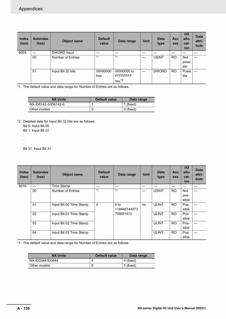
Appendices
A - 138 NX-series Digital I/O Unit User’s Manual (W521)
*1. The default value and data range for Number of Entries are as follows.
*2. Detailed data for Input Bit 32 bits are as follows.Bit 0: Input Bit 00Bit 1: Input Bit 01···Bit 31: Input Bit 31
*1. The default value and data range for Number of Entries are as follows.
Index(hex)
Subindex(hex) Object name Default
value Data range Unit Data type
Access
I/O allo-cat-ion
Data attri-bute
6003 --- DWORD Input --- --- --- --- --- --- ---00 Number of Entries *1 *1 --- USINT RO Not
possible
---
01 Input Bit 32 bits 00000000 hex
00000000 to FFFFFFFF hex*2
--- DWORD RO Possible
---
NX Units Default value Data rangeNX-ID6142-5/ID6142-6 1 1 (fixed)Other models 0 0 (fixed)
Index(hex)
Subindex(hex) Object name Default
value Data range Unit Data type
Access
I/O allo-cat-ion
Data attri-bute
6010 --- Time Stamp --- --- --- --- --- --- ---00 Number of Entries *1 *1 --- USINT RO Not
pos-sible
---
01 Input Bit 00 Time Stamp 0 0 to +18446744073709551615
ns ULINT RO Pos-sible
---
02 Input Bit 01 Time Stamp ULINT RO Pos-sible
---
03 Input Bit 02 Time Stamp ULINT RO Pos-sible
---
04 Input Bit 03 Time Stamp ULINT RO Pos-sible
---
NX Units Default value Data rangeNX-ID3344/ID3444 4 4 (fixed)Other models 0 0 (fixed)

A - 139
Appendices
NX-series Digital I/O Unit User’s Manual (W521)
A-5 List of N
X Objects
A
A-5-2 D
igital Input Units
This section lists other objects.
*1. The default value and data range for Number of Entries are as follows.
*2. The meaning of the set values for Input Filter Value Setting is as follows.
*3. The meaning of the set values for Input Filter Mode Setting is as follows.
Other Objects
Index(hex)
Subindex(hex) Object name Default
value Data range Unit Data type
Access
I/O allo-cat-ion
Data attri-bute
5000 --- Input Filter Setting --- --- --- --- --- --- ---00 Number of Entries *1 *1 --- USINT RO Not
pos-sible
---
01 Input Filter Value Setting 3 0 to 11 *2 --- USINT RW Not pos-sible
Y
02 Input Filter Mode Setting 0 0/1 *3 --- USINT RW Not pos-sible
Y
NX Units Default value Data rangeNX-ID3317/ID3417/ID4342/ID4442/ID5142-1/ID5142-5/ID5342/ID5442/ID6142-5/ID6142-6/IA3117
2 2 (fixed)
Other models 0 0 (fixed)
Set value Meaning0 No Filter1 0.25 ms2 0.5 ms3 1 ms4 2 ms5 4 ms6 8 ms7 16 ms8 32 ms9 64 ms10 128 ms11 256 ms
Set value Meaning0 Enable ON Filter and OFF Filter1 Enable Only OFF Filter

Appendices
A - 140 NX-series Digital I/O Unit User’s Manual (W521)
*1. The default value and data range for Number of Entries are as follows.
*2. The meaning of the set values for Input Filter Value Setting is as follows.
*3. The meaning of the set values for Input Filter Mode Setting is as follows.
Index(hex)
Subindex(hex) Object name Default
value Data range Unit Data type
Access
I/O allo-cat-ion
Data attri-bute
5001 --- Input Filter Setting --- --- --- --- --- --- ---00 Number of Entries *1 *1 --- USINT RO Not
pos-sible
---
01 Input Filter Value Setting 4 0 to 9 *2 --- USINT RW Not pos-sible
Y
02 Input Filter Mode Setting 0 0/1 *3 --- USINT RW Not pos-sible
Y
NX Units Default value Data rangeNX-ID3343/ID3443 2 2 (fixed)Other models 0 0 (fixed)
Set value Meaning0 No Filter1 1 μs2 2 μs3 4 μs4 8 μs5 16 μs6 32 μs7 64 μs8 128 μs9 256 μs
Set value Meaning0 Enable ON Filter and OFF Filter1 Enable Only OFF Filter

A - 141
Appendices
NX-series Digital I/O Unit User’s Manual (W521)
A-5 List of N
X Objects
A
A-5-2 D
igital Input Units*1. The default value and data range for Number of Entries are as follows.
*2. The meaning of the set values for Input Bit Trigger Setting is as follows.
Index(hex)
Subindex(hex) Object name Default
value Data range Unit Data type
Access
I/O allo-cat-ion
Data attri-bute
5005 --- Time Stamp (Trigger Set-ting)
--- --- --- --- --- --- ---
00 Number of Entries *1 *1 --- USINT RO Not pos-sible
---
01 Input Bit 00 Trigger Setting FALSE TRUE or FALSE *2
--- BOOL RW Not pos-sible
Y
02 Input Bit 01 Trigger Setting FALSE --- BOOL RW Not pos-sible
Y
03 Input Bit 02 Trigger Setting FALSE --- BOOL RW Not pos-sible
Y
04 Input Bit 03 Trigger Setting FALSE --- BOOL RW Not pos-sible
Y
NX Units Default value Data rangeNX-ID3344/ID3444 4 4 (fixed)Other models 0 0 (fixed)
Set value MeaningFALSE Rising EdgeTRUE Falling Edge
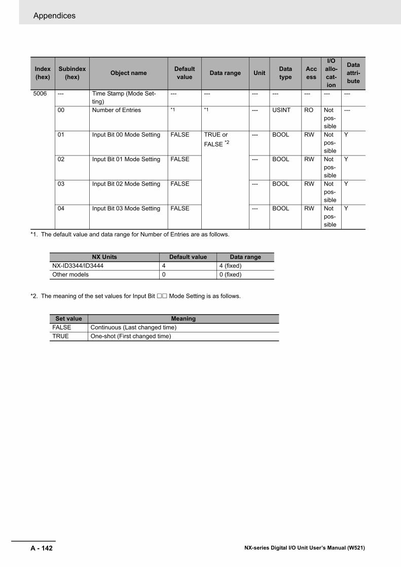
Appendices
A - 142 NX-series Digital I/O Unit User’s Manual (W521)
*1. The default value and data range for Number of Entries are as follows.
*2. The meaning of the set values for Input Bit Mode Setting is as follows.
Index(hex)
Subindex(hex) Object name Default
value Data range Unit Data type
Access
I/O allo-cat-ion
Data attri-bute
5006 --- Time Stamp (Mode Set-ting)
--- --- --- --- --- --- ---
00 Number of Entries *1 *1 --- USINT RO Not pos-sible
---
01 Input Bit 00 Mode Setting FALSE TRUE or FALSE *2
--- BOOL RW Not pos-sible
Y
02 Input Bit 01 Mode Setting FALSE --- BOOL RW Not pos-sible
Y
03 Input Bit 02 Mode Setting FALSE --- BOOL RW Not pos-sible
Y
04 Input Bit 03 Mode Setting FALSE --- BOOL RW Not pos-sible
Y
NX Units Default value Data rangeNX-ID3344/ID3444 4 4 (fixed)Other models 0 0 (fixed)
Set value MeaningFALSE Continuous (Last changed time)TRUE One-shot (First changed time)

A - 143
Appendices
NX-series Digital I/O Unit User’s Manual (W521)
A-5 List of N
X Objects
A
A-5-3 D
igital Output U
nits
This object gives the product information.
A-5-3 Digital Output Units
Unit Information Objects
Index(hex)
Subindex(hex) Object name Default
value Data range Unit Data type
Access
I/O allo-cation
Data attri-bute
1000 --- NX Bus Identity --- --- --- --- --- --- ---00 Number of Entries 7 7 --- USINT RO Not
possible---
02 Model *1
*1. The product models are assigned in ascending order from the lowest number of array elements. Any remainder elements are filled with spaces.
--- --- ARRAY [0..11] OF BYTE
RO Not possible
---
03 Device Type *2
*2. The device types are assigned for each product Unit type.Bits 0 to 31: Device type
--- --- UDINT RO Not possible
---
04 Product Code *3
*3. The product codes are assigned for each product model.Bits 0 to 31: Product code
--- --- UDINT RO Not possible
---
05 Vendor Code 00000001 hex *4
*4. OMRON vendor code
--- --- UDINT RO Not possible
---
06 Unit Version *5
*5. Bits 24 to 31: Integer part of the Unit version.Bits 16 to 23: Fractional part of the Unit version.Bits 0 to 15: Reserved(Example) For Ver.1.0, 0100 hex
--- --- UDINT RO Not possible
---
07 Serial Number *6
*6. A unique serial number is assigned for each product unit.Bits 0 to 31: Serial number
00000000 to FFFFFFFF hex
--- UDINT RO Not possible
---
1001 --- Production Info --- --- --- --- --- --- ---00 Number of Entries 2 2 --- USINT RO Not
possible---
01 Lot Number *7
*7. The year, month, and day of production are assigned to the "lot number".Bits 24 to 31: Date of productionBits 16 to 23: Month of productionBits 8 to 15: Year of productionBits 0 to 7: Reserved
00000000 to FFFFFFFF hex
--- UDINT RO Not possible
---
02 Hardware Version *8
*8. The hardware version is assigned in ascending order from the earliest number of array elements. Any remainder elements are filled with spaces.
--- --- ARRAY [0..19] OF BYTE
RO Not possible
---

Appendices
A - 144 NX-series Digital I/O Unit User’s Manual (W521)
These objects accept I/O allocations.
You cannot access the objects that are described below with the Read NX Unit Object instruction, Write NX Unit Object instruction, or other messages.
*1. The default value and data range for Number of Entries are as follows.
Objects That Accept I/O Allocations
Index(hex)
Subindex(hex) Object name Default
value Data range Unit Data type
Access
I/O allo-cat-ion
Data attri-bute
7000 --- Bit Output --- --- --- --- --- --- ---00 Number of Entries *1 *1 --- USINT RO Not
pos-sible
---
01 Output Bit 00 FALSE TRUE or FALSE
--- BOOL RW Pos-sible
N
02 Output Bit 01 FALSE TRUE or FALSE
--- BOOL RW Pos-sible
N
03 Output Bit 02 FALSE TRUE or FALSE
--- BOOL RW Pos-sible
N
04 Output Bit 03 FALSE TRUE or FALSE
--- BOOL RW Pos-sible
N
NX Units Default value Data rangeNX-OD3121/OD3153/OD3256/OD3257/OD3268
4 4 (fixed)
NX-OD2154/OD2258/OC2633/OC2733 2 2 (fixed)Other models 0 0 (fixed)

A - 145
Appendices
NX-series Digital I/O Unit User’s Manual (W521)
A-5 List of N
X Objects
A
A-5-3 D
igital Output U
nits
*1. The default value and data range for Number of Entries are as follows.
*2. Detailed data for Output Bit 8 bits are as follows.Bit 0: Output Bit 00Bit 1: Output Bit 01···Bit 7: Output Bit 07
*1. The default value and data range for Number of Entries are as follows.
*2. Detailed data for Output Bit 16 bits are as follows.Bit 0: Output Bit 00Bit 1: Output Bit 01···Bit 15: Output Bit 15
Index(hex)
Subindex(hex) Object name Default
value Data range Unit Data type
Access
I/O allo-cat-ion
Data attri-bute
7001 --- BYTE Output --- --- --- --- --- --- ---00 Number of Entries *1 *1 --- USINT RO Not
pos-sible
---
01 Output Bit 8 bits 00 hex 00 to FF hex --- BYTE RW Pos-sible
N
NX Units Default value Data rangeNX-OD4121/OD4256/OC4633 1 1 (fixed)Other models 0 0 (fixed)
Index(hex)
Subindex(hex) Object name Default
value Data range Unit Data type
Access
I/O allo-cat-ion
Data attri-bute
7002 --- Word Output --- --- --- --- --- --- ---00 Number of Entries *1 *1 --- USINT RO Not
pos-sible
---
01 Output Bit 16 bits 0000 hex 0000 to FFFF hex
--- WORD RW Pos-sible
N
NX Units Default value Data rangeNX-OD5121/OD5121-1/OD5121-5/OD5256/OD5256-1/OD5256-5
1 1 (fixed)
Other models 0 0 (fixed)
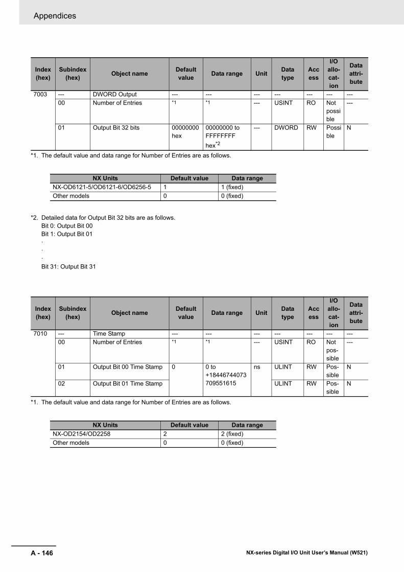
Appendices
A - 146 NX-series Digital I/O Unit User’s Manual (W521)
*1. The default value and data range for Number of Entries are as follows.
*2. Detailed data for Output Bit 32 bits are as follows.Bit 0: Output Bit 00Bit 1: Output Bit 01···Bit 31: Output Bit 31
*1. The default value and data range for Number of Entries are as follows.
Index(hex)
Subindex(hex) Object name Default
value Data range Unit Data type
Access
I/O allo-cat-ion
Data attri-bute
7003 --- DWORD Output --- --- --- --- --- --- ---00 Number of Entries *1 *1 --- USINT RO Not
possible
---
01 Output Bit 32 bits 00000000 hex
00000000 to FFFFFFFF hex*2
--- DWORD RW Possible
N
NX Units Default value Data rangeNX-OD6121-5/OD6121-6/OD6256-5 1 1 (fixed)Other models 0 0 (fixed)
Index(hex)
Subindex(hex) Object name Default
value Data range Unit Data type
Access
I/O allo-cat-ion
Data attri-bute
7010 --- Time Stamp --- --- --- --- --- --- ---00 Number of Entries *1 *1 --- USINT RO Not
pos-sible
---
01 Output Bit 00 Time Stamp 0 0 to +18446744073709551615
ns ULINT RW Pos-sible
N
02 Output Bit 01 Time Stamp ULINT RW Pos-sible
N
NX Units Default value Data rangeNX-OD2154/OD2258 2 2 (fixed)Other models 0 0 (fixed)

A - 147
Appendices
NX-series Digital I/O Unit User’s Manual (W521)
A-5 List of N
X Objects
A
A-5-3 D
igital Output U
nits
*1. The default value and data range for Number of Entries are as follows.
*2. The meaning of the set values for Output BitOutput Status is as follows.
Index(hex)
Subindex(hex) Object name Default
value Data range Unit Data type
Access
I/O allo-cat-ion
Data attri-bute
6011 --- Specified Time Stamp Out-put Status
--- --- --- --- --- --- ---
00 Number of Entries *1 *1 --- USINT RO Not pos-sible
---
01 Output Bit 00 Output Sta-tus
FALSE TRUE or FALSE *2
--- BOOL RO Pos-sible
N
02 Output Bit 01 Output Sta-tus
BOOL RO Pos-sible
N
NX Units Default value Data rangeNX-OD2154/OD2258 2 2 (fixed)Other models 0 0 (fixed)
Set value MeaningFALSE Output completionTRUE Waiting for output to refresh

Appendices
A - 148 NX-series Digital I/O Unit User’s Manual (W521)
This section lists other objects.
*1. The default value and data range for Number of Entries are as follows.
*2. The meaning of the set values for Load Rejection Output for Output Bit is as follows.
Other Objects
Index(hex)
Subindex(hex) Object name Default
value Data range Unit Data type
Access
I/O allo-cat-ion
Data attri-bute
5010 --- Load Rejection Output Set-ting
--- --- --- --- --- --- ---
00 Number of Entries *1 *1 --- USINT RO Not pos-sible
---
01 Load Rejection Output for Output Bit 00
FALSE TRUE or FALSE *2
--- BOOL RW Not pos-sible
Y
02 Load Rejection Output for Output Bit 01
FALSE --- BOOL RW Not pos-sible
Y
03 Load Rejection Output for Output Bit 02
FALSE --- BOOL RW Not pos-sible
Y
04 Load Rejection Output for Output Bit 03
FALSE --- BOOL RW Not pos-sible
Y
NX Units Default value Data rangeNX-OD3121/OD3153/OD3256/OD3257/OD3268
4 4 (fixed)
NX-OC2633/OC2733 2 2 (fixed)Other models 0 0 (fixed)
Set value MeaningFALSE OFFTRUE Hold the present value.

A - 149
Appendices
NX-series Digital I/O Unit User’s Manual (W521)
A-5 List of N
X Objects
A
A-5-3 D
igital Output U
nits
*1. The default value and data range for Number of Entries are as follows.
*2. The detailed data and meaning of the set values for Load Rejection Output for Output Bit (8 bits) are as follows.Bit 0: Load Rejection Output for Output Bit 00Bit 1: Load Rejection Output for Output Bit 01···Bit 7: Load Rejection Output for Output Bit 07
Index(hex)
Subindex(hex) Object name Default
value Data range Unit Data type
Access
I/O allo-cat-ion
Data attri-bute
5011 --- Load Rejection Byte Set-ting
--- --- --- --- --- --- ---
00 Number of Entries *1 *1 --- USINT RO Not pos-sible
---
01 Load Rejection Output for Output Bit (8 bits)
00 hex 00 to FF hex*2 --- BYTE RW Not pos-sible
Y
NX Units Default value Data rangeNX-OD4121/OD4256/OC4633 1 1 (fixed)Other models 0 0 (fixed)
Set value Meaning0 OFF1 Hold the present value.

Appendices
A - 150 NX-series Digital I/O Unit User’s Manual (W521)
*1. The default value and data range for Number of Entries are as follows.
*2. The detailed data and meaning of the set values for Load Rejection Output for Output Bit (16 bits) are as follows.Bit 0: Load Rejection Output for Output Bit 00Bit 1: Load Rejection Output for Output Bit 01···Bit 15: Load Rejection Output for Output Bit 15
Index(hex)
Subindex(hex) Object name Default
value Data range Unit Data type
Access
I/O allo-cat-ion
Data attri-bute
5012 --- Load Rejection Word Set-ting
--- --- --- --- --- --- ---
00 Number of Entries *1 *1 --- USINT RO Not pos-sible
---
01 Load Rejection Output for Output Bit (16 bits)
0000 hex 0000 to FFFF hex*2
--- WORD RW Not pos-sible
Y
NX Units Default value Data rangeNX-OD5121/OD5121-1/OD5121-5/OD5256/OD5256-1/OD5256-5
1 1 (fixed)
Other models 0 0 (fixed)
Set value Meaning0 OFF1 Hold the present value.

A - 151
Appendices
NX-series Digital I/O Unit User’s Manual (W521)
A-5 List of N
X Objects
A
A-5-3 D
igital Output U
nits
*1. The default value and data range for Number of Entries are as follows.
*2. The detailed data and meaning of the set values for Load Rejection Output for Output Bit (32 bits) are as follows.Bit 0: Load Rejection Output for Output Bit 00Bit 1: Load Rejection Output for Output Bit 01···Bit 31: Load Rejection Output for Output Bit 31
Index(hex)
Subindex(hex) Object name Default
value Data range Unit Data type
Access
I/O allo-cat-ion
Data attri-bute
5013 --- Load Rejection DWord Setting
--- --- --- --- --- --- ---
00 Number of Entries *1 *1 --- USINT RO Not possible
---
01 Load Rejection Output for Output Bit (32 bits)
00000000 hex
00000000 to FFFFFFFF hex *2
--- DWORD RW Not possible
Y
NX Units Default value Data rangeNX-OD6121-5/OD6121-6/OD6256-5 1 1 (fixed)Other models 0 0 (fixed)
Set value Meaning0 OFF1 Hold the present value.

Appendices
A - 152 NX-series Digital I/O Unit User’s Manual (W521)
This object gives the product information.
A-5-4 Digital Mixed I/O Units
Unit Information Objects
Index(hex)
Subindex(hex) Object name Default
value Data range Unit Data type
Access
I/O allo-cat-ion
Data attri-bute
1000 --- NX Bus Identity --- --- --- --- --- --- ---00 Number of Entries 7 7 --- USINT RO Not
pos-sible
---
02 Model *1
*1. The product models are assigned in ascending order from the lowest number of array elements. Any remainder elements are filled with spaces.
--- --- ARRAY [0..11] OF BYTE
RO Not pos-sible
---
03 Device Type *2
*2. The device types are assigned for each product Unit type. Bits 0 to 31: Device type
--- --- UDINT RO Not pos-sible
---
04 Product Code *3
*3. The product codes are assigned for each product model. Bits 0 to 31: Product code
--- --- UDINT RO Not pos-sible
---
05 Vendor Code 00000001 hex *4
*4. OMRON vendor code
--- --- UDINT RO Not pos-sible
---
06 Unit Version *5
*5. Bits 24 to 31: Integer part of the Unit version.Bits 16 to 23: Fractional part of the Unit version.Bits 0 to 15: Reserved (Example) For Ver.1.0, 0100 hex
--- --- UDINT RO Not pos-sible
---
07 Serial Number *6
*6. A unique serial number is assigned for each product unit. Bits 0 to 31: Serial number
00000000 to FFFFFFFF hex
--- UDINT RO Not pos-sible
---
1001 --- Production Info --- --- --- --- --- --- ---00 Number of Entries 2 2 --- USINT RO Not
pos-sible
---
01 Lot Number *7 00000000 to FFFFFFFF hex
--- UDINT RO Not pos-sible
---
02 Hardware Version *8 --- --- ARRAY [0..19] OF BYTE
RO Not pos-sible
---

A - 153
Appendices
NX-series Digital I/O Unit User’s Manual (W521)
A-5 List of N
X Objects
A
A-5-4 D
igital Mixed I/O
Units
These objects accept I/O allocations.
You cannot access the objects that are described below with the Read NX Unit Object instruction, Write NX Unit Object instruction, or other messages.
*1. The default value and data range for Number of Entries are as follows.
*2. Detailed data for Input Bit 16 bits are as follows. Bit 0: Input Bit 00Bit 1: Input Bit 01···Bit 15: Input Bit 15
*7. The year, month, and day of production are assigned to the "lot number". Bits 24 to 31: Date of productionBits 16 to 23: Month of productionBits 8 to 15: Year of productionBits 0 to 7: Reserved
*8. The hardware version is assigned in ascending order from the earliest number of array elements. Any remainder elements are filled with spaces.
Objects That Accept I/O Allocations
Index(hex)
Subindex(hex) Object name Default
value Data range Unit Data type
Access
I/O allo-cat-ion
Data attri-bute
6002 --- WORD Input --- --- --- --- --- --- ---00 Number of Entries *1 *1 --- USINT RO Not
pos-sible
---
01 Input Bit 16 bits 0000 hex 0000 to FFFF hex *2
--- WORD RO Pos-sible
---
NX Units Default value Data rangeNX-MD6121-5/MD6121-6/MD6256-5 1 1 (fixed)Other models 0 0 (fixed)

Appendices
A - 154 NX-series Digital I/O Unit User’s Manual (W521)
*1. The default value and data range for Number of Entries are as follows.
*2. Detailed data for Output Bit 16 bits are as follows. Bit 0: Output Bit 00Bit 1: Output Bit 01···Bit 15: Output Bit 15
Index(hex)
Subindex(hex) Object name Default
value Data range Unit Data type
Access
I/O allo-cat-ion
Data attri-bute
7002 --- WORD Output --- --- --- --- --- --- ---00 Number of Entries *1 *1 --- USINT RO Not
pos-sible
---
01 Output Bit 16 bits 0000 hex 0000 to FFFF hex *2
--- WORD RW Pos-sible
N
NX Units Default value Data rangeNX-MD6121-5/MD6121-6/MD6256-5 1 1 (fixed)Other models 0 0 (fixed)

A - 155
Appendices
NX-series Digital I/O Unit User’s Manual (W521)
A-5 List of N
X Objects
A
A-5-4 D
igital Mixed I/O
Units
This section lists other objects.
*1. The default value and data range for Number of Entries are as follows.
*2. The meaning of the set values for Input Filter Value Setting is as follows.
*3. The meaning of the set values for Input Filter Mode Setting is as follows.
Other Objects
Index(hex)
Subindex(hex) Object name Default
value Data range Unit Data type
Access
I/O allo-cat-ion
Data attri-bute
5000 --- Input Filter Setting --- --- --- --- --- --- ---00 Number of Entries *1 *1 --- USINT RO Not
pos-sible
---
01 Input Filter Value Setting 3 0 to 11 *2 --- USINT RW Not pos-sible
Y
02 Input Filter Mode Setting 0 0/1 *3 --- USINT RW Not pos-sible
Y
NX Units Default value Data rangeNX-MD6121-5/MD6121-6/MD6256-5 2 2 (fixed)Other models 0 0 (fixed)
Set value Meaning0 No Filter1 0.25 ms2 0.5 ms3 1 ms4 2 ms5 4 ms6 8 ms7 16 ms8 32 ms9 64 ms10 128 ms11 256 ms
Set value Meaning0 Enable ON Filter and OFF Filter1 Enable Only OFF Filter

Appendices
A - 156 NX-series Digital I/O Unit User’s Manual (W521)
*1. The default value and data range for Number of Entries are as follows.
*2. The detailed data and meaning of the set values for Load Rejection Output for Output Bit (16 bits) are as follows. Bit 0: Load Rejection Output for Output Bit 00Bit 1: Load Rejection Output for Output Bit 01···Bit 15: Load Rejection Output for Output Bit 15
Index(hex)
Subindex(hex) Object name Default
value Data range Unit Data type
Access
I/O allo-cat-ion
Data attri-bute
5012 --- Load Rejection Word Set-ting
--- --- --- --- --- --- ---
00 Number of Entries *1 *1 --- USINT RO Not pos-sible
---
01 Load Rejection Output for Output Bit (16 bits)
0000 hex 0000 to FFFF hex *2
--- WORD RW Not pos-sible
Y
NX Units Default value Data rangeNX-MD6121-5/MD6121-6/MD6256-5 1 1 (fixed)Other models 0 0 (fixed)
Set value Meaning0 OFF1 Hold the present value.

A - 157
Appendices
NX-series Digital I/O Unit User’s Manual (W521)
A-6 List of Screw
less Clam
ping Terminal
Block M
odels
A
A-6-1 M
odel Notation
A-6 List of Screwless Clamping Terminal Block Models
This section explains how to read the screwless clamping terminal block model numbers and shows the model number table.
The screwless clamping terminal block models are assigned based on the following rules.
The following table shows a list of screwless clamping terminal blocks.
Note When you purchase a terminal block, purchase an NX-TB2.
A-6-1 Model Notation
A-6-2 List of Terminal Block Models
Terminal block model Number of terminals Ground terminal mark Terminal current capacityNX-TBA081 8 Not provided 4 ANX-TBA121 12NX-TBA161 16NX-TBB121 12NX-TBB161 16NX-TBA082 8 10 ANX-TBA122 12NX-TBA162 16NX-TBB082 8NX-TBB122 12NX-TBB162 16NX-TBC082 8 ProvidedNX-TBC162 16
NNX -T-TB
Product type TB: Terminal block
Terminal specifications A: Column letter indication A/B, without functional ground terminal B: Column letter indication C/D, without functional ground terminal C: Column letter indication A/B, with functional ground terminal
Number of terminals 08: 8 terminals 12: 12 terminals 16: 16 terminals
Other specifications 1: Terminal current capacity of 4 A 2: Terminal current capacity of 10 A

Appendices
A - 158 NX-series Digital I/O Unit User’s Manual (W521)
A-7 Version Information with CPU Units
This section provides version-related information when connecting Units to a CPU Unit.
This section describes the relationship between the unit versions of each Unit and the CPU Unit, and Sysmac Studio version, and the specification changes for each unit version of each Unit.
The relationship between the unit versions of each Unit and the CPU Unit, and Sysmac Studio version are shown below.
The items that are used in the version combination tables are given below.
Refer to the user's manual for the CPU Unit for the models of CPU Unit to which NX Units can be connected.
• With the combinations of the unit versions/versions shown below, you can use the functions that are supported by the unit version of the Unit model. Use the unit versions/versions (or the later/higher unit versions/versions) that correspond to the NX Unit models and the unit versions. You cannot use the specifications that were added or changed for the relevant NX Unit models and the unit versions unless you use the corresponding unit versions/versions.
• Depending on the type and model of the Unit to which the NX Unit is connected, some Units do not have the corresponding versions given in the table. If a Unit does not have the specified version, sup-port is provided by the oldest available version after the specified version. Refer to the user’s manu-als for the specific Units for the relation between models and versions.
• If you use the corresponding unit versions/versions given in the following table or later/higher ver-sions, refer to the version information in the user’s manual for the CPU Unit.
A-7-1 Relationship between Unit Versions of Units
Interpreting the Version Combination Tables
NX Unit Corresponding unit versions/versionsModel Unit version CPU Unit Sysmac Studio
Model number of NX Units.
Unit versions of NX Units. Unit versions of the CPU that are compatible with the NX Units.
Sysmac Studio versions that are compatible with the NX Units and CPU Unit.
Version Combination Tables

A - 159
Appendices
NX-series Digital I/O Unit User’s Manual (W521)
A-7 Version Inform
ation with C
PU U
nits
A
A-7-1 R
elationship between U
nit Versions of Units
NX Unit Corresponding unit versions/versionsModel Unit version CPU Unit Sysmac Studio
NX-ID3317 Ver.1.0 Ver.1.13 Ver.1.17NX-ID3343NX-ID3344NX-ID3417NX-ID3443NX-ID3444NX-ID4342NX-ID4442NX-ID5142-1NX-ID5142-5NX-ID5342NX-ID5442NX-ID6142-5NX-ID6142-6NX-IA3117NX-OD2154NX-OD2258NX-OD3121NX-OD3153NX-OD3256NX-OD3257NX-OD3268NX-OD4121NX-OD4256NX-OD5121NX-OD5121-1NX-OD5121-5NX-OD5256NX-OD5256-1NX-OD5256-5NX-OD6121-5NX-OD6121-6NX-OD6256-5NX-OC2633NX-OC2733NX-OC4633NX-MD6121-5NX-MD6121-6NX-MD6256-5

Appendices
A - 160 NX-series Digital I/O Unit User’s Manual (W521)
A-8 Version Information with Communica-tions Coupler Units
This section provides version-related information when connecting Units to a Communications Coupler Unit.
Version information is provided separately for each Communications Coupler Unit that an NX Unit is connected to.
The relationship between the unit versions of each Unit, EtherCAT Coupler Unit, CPU Unit and Indus-trial PC, and versions of the Sysmac Studio are shown below.
The items that are used in the version combination tables are given below.
The version combination table is given below.• With the combinations of the unit versions/versions shown below, you can use the functions that are
supported by the unit version of the Unit model. Use the unit versions/versions (or the later/higher unit versions/versions) that correspond to the NX Unit models and the unit versions. You cannot use the specifications that were added or changed for the relevant NX Unit models and the unit versions unless you use the corresponding unit versions/versions.
• Depending on the type and model of the Unit to which the NX Unit is connected, some Units do not have the corresponding versions given in the table. If a Unit does not have the specified version, sup-port is provided by the oldest available version after the specified version. Refer to the user’s manu-als for the specific Units for the relation between models and versions.
• You cannot connect the relevant NX Unit to the target Communications Coupler Unit if “---” is shown in the corresponding unit versions/versions column.
• If you use the corresponding unit versions/versions given in the following table or later/higher ver-sions, refer to the version information in the user’s manual for the Communications Coupler Unit, CPU Unit, and Industrial PC.
A-8-1 Connection to an EtherCAT Coupler Unit
Relationship between Unit Versions of Units
NX Unit Corresponding unit versions/versions
Model Unit version EtherCAT Coupler Unit
CPU Unit or Indus-trial PC Sysmac Studio
Model numbers of NX Units.
Unit versions of NX Units.
Unit versions of EherCAT Coupler Units that are com-patible with the NX Units.
Unit versions of NJ/NX-series CPU Units or NY-series Industrial PCs that are compatible with the EtherCAT Cou-pler Units.
Sysmac Studio ver-sions that are com-patible with the NX Units, EtherCAT Coupler Units, CPU Units, and Industrial PCs.

A - 161
Appendices
NX-series Digital I/O Unit User’s Manual (W521)
A-8 Version Inform
ation with C
omm
unica-tions C
oupler Units
A
A-8-1 C
onnection to an EtherC
AT Coupler U
nit
*1. If you use a CPU Unit, the instructions for time stamp refreshing are supported by CPU Units with unit version 1.06 or later. If you do not use instructions for time stamp refreshing, you can use version 1.05. Refer to the instructions reference manual for the connected CPU Unit or Industrial PC for details on the instructions for time stamp refreshing.
NX Unit Corresponding unit versions/versions
Model Unit version EtherCAT Coupler Unit
CPU Unit or Industrial PC Sysmac Studio
NX-ID3317 Ver.1.0 Ver.1.0 Ver.1.05 Ver.1.06NX-ID3343NX-ID3344 Ver.1.1 Ver.1.06*1 Ver.1.07
NX-ID3417 Ver.1.0 Ver.1.05 Ver.1.06NX-ID3443NX-ID3444 Ver.1.1 Ver.1.06*1 Ver.1.07
NX-ID4342 Ver.1.0 Ver.1.05 Ver.1.06NX-ID4442NX-ID5142-1 Ver.1.13NX-ID5142-5 Ver.1.10NX-ID5342 Ver.1.06NX-ID5442NX-DA3603 Ver.1.10NX-DA3603 Ver.1.13NX-IA3117 Ver.1.08NX-OD2154 Ver.1.1 Ver.1.06*1 Ver.1.07NX-OD2258NX-OD3121 Ver.1.0 Ver.1.05 Ver.1.06NX-OD3153NX-OD3256NX-OD3257NX-OD3268 Ver.1.13NX-OD4121 Ver.1.06NX-OD4256NX-OD5121NX-OD5121-1 Ver.1.13NX-OD5121-5 Ver.1.10NX-OD5256 Ver.1.06NX-OD5256-1 Ver.1.13NX-OD5256-5 Ver.1.10NX-OD6121-5NX-OD6121-6 Ver.1.13NX-OD6256-5 Ver.1.10NX-OC2633 Ver.1.06NX-OC2733 Ver.1.08NX-OC4633 Ver.1.17NX-MD6121-5 Ver.1.10NX-MD6121-6 Ver.1.13NX-MD6256-5 Ver.1.10

Appendices
A - 162 NX-series Digital I/O Unit User’s Manual (W521)
The relationship between the unit versions of each Unit, EtherNet/IP Coupler Unit, CPU Unit and Indus-trial PC, and versions of the Sysmac Studio and NX-IO Configurator are shown below.
The items that are used in the version combination tables are given below.
The version combination table is given below.• With the combinations of the unit versions/versions shown below, you can use the functions that are
supported by the unit version of the Unit model. Use the unit versions/versions (or the later/higher unit version/versions) that correspond to the NX Unit models and the unit versions. You cannot use the specifications that were added or changed for the relevant NX Unit models and the unit versions unless you use the corresponding unit versions/versions.
• Depending on the type and model of the Unit to which the NX Unit is connected, some Units do not have the corresponding versions given in the table. If a Unit does not have the specified version, sup-port is provided by the oldest available version after the specified version. Refer to the user’s manu-als for the specific Units for the relation between models and versions.
• You cannot connect the relevant NX Unit to the target Communications Coupler Unit if “---” is shown in the corresponding unit versions/versions column.
• If you use the corresponding unit versions/versions given in the following table or later/higher ver-sions, refer to the version information in the user’s manual for the Communications Coupler Unit, CPU Unit, and Industrial PC.
A-8-2 Connection to an EtherNet/IP Coupler Unit
Relationship between Unit Versions of Units
NX Unit Corresponding unit versions/versions
Model Unit version
Application with an NJ/NX/NY-series Con-troller Application with a CS/CJ/CP-series PLC
EtherNet/IP Coupler Unit
CPU Unit or Industrial
PC
Sysmac Stu-dio
EtherNet/IP Coupler Unit
Sysmac Stu-dio
NX-IO Con-figurator
Model num-ber of NX Unit
Unit version of the NX Unit
Unit version of Ether-Net/IP Cou-pler Unit that is compati-ble with the NX Unit
Unit version of NJ/NX-series CPU Unit or NY-series Industrial PC that is com-patible with the Ether-Net/IP Cou-pler Unit
Sysmac Stu-dio version that is com-patible with the NX Unit, EtherNet/IP Coupler Unit, CPU Unit, and Industrial PC
Unit version of Ether-Net/IP Cou-pler Unit that is compati-ble with the NX Unit
Sysmac Stu-dio version that is com-patible with the NX Unit, EtherNet/IP Coupler Unit, and CPU Unit
NX-IO Con-figurator ver-sion that is compatible with the NX Unit, Ether-Net/IP Cou-pler Unit, and CPU Unit

A - 163
Appendices
NX-series Digital I/O Unit User’s Manual (W521)
A-8 Version Inform
ation with C
omm
unica-tions C
oupler Units
A
A-8-2 C
onnection to an EtherN
et/IP C
oupler Unit
NX Unit Corresponding unit versions/versions
Model Unit ver-sion
Application with an NJ/NX/NY-series Controller *1
*1. Refer to the user’s manual for the EtherNet/IP Coupler Units for information on the unit versions of EtherNet/IP Units that are compatible with EtherNet/IP Coupler Units.
Application with a CS/CJ/CP-series PLC *2
*2. Refer to the user’s manual for the EtherNet/IP Coupler Units for information on the unit versions of CPU Units and EtherNet/IP Units that are compatible with EtherNet/IP Coupler Units.
EtherNet/IP Coupler Unit
CPU Unit or Industrial PC
Sysmac Studio
EtherNet/IP Coupler Unit
Sysmac Studio
NX-IO Config-urator *3
*3. For connection to an EtherNet/IP Coupler Unit with unit version 1.0, connection is supported only for a connection to the peripheral USB port on the EtherNet/IP Coupler Unit. You cannot connect by any other path. If you need to connect by another path, use an EtherNet/IP Coupler Unit with unit version 1.2 or later.
NX-ID3317 Ver. 1.0 Ver. 1.2 Ver. 1.14 Ver. 1.19 Ver. 1.0 Ver. 1.10 Ver. 1.00NX-ID3343NX-ID3344 --- --- --- --- --- ---NX-ID3417 Ver. 1.2 Ver. 1.14 Ver. 1.19 Ver. 1.0 Ver. 1.10 Ver. 1.00NX-ID3443NX-ID3444 --- --- --- --- --- ---NX-ID4342 Ver. 1.2 Ver. 1.14 Ver. 1.19 Ver. 1.0 Ver. 1.10 Ver. 1.00NX-ID4442NX-ID5142-1 Ver. 1.13NX-ID5142-5 Ver. 1.10NX-ID5342NX-ID5442NX-ID6142-5NX-ID6142-6 Ver. 1.13NX-IA3117 Ver. 1.10NX-OD2154 --- --- --- --- --- ---NX-OD2258NX-OD3121 Ver. 1.2 Ver. 1.14 Ver. 1.19 Ver. 1.0 Ver. 1.10 Ver. 1.00NX-OD3153NX-OD3256NX-OD3257NX-OD3268 Ver. 1.13NX-OD4121 Ver. 1.10NX-OD4256NX-OD5121NX-OD5121-1 Ver. 1.13NX-OD5121-5 Ver. 1.10NX-OD5256NX-OD5256-1 Ver. 1.13NX-OD5256-5 Ver. 1.10NX-OD6121-5NX-OD6121-6 Ver. 1.13NX-OD6256-5 Ver. 1.10NX-OC2633NX-OC2733NX-OC4633 Ver. 1.17NX-MD6121-5 Ver. 1.10NX-MD6121-6 Ver. 1.13NX-MD6256-5 Ver. 1.10

Appendices
A - 164 NX-series Digital I/O Unit User’s Manual (W521)
A-9 Displaying the Edit Unit Operation Settings Tab Page
This section describes how to display the Edit Unit Operation Settings Tab Page that is used to create Unit operation settings on the Sysmac Studio for the NX Units connected to the CPU Unit.
You can use the methods described below to display the Edit Unit Operation Settings Tab Page on the CPU and Expansion Racks Tab Page on the Sysmac Studio.
Refer to the Sysmac Studio Version 1 Operation Manual (Cat. No. W504) for the method of displaying the CPU and Expansion Racks Tab Page.
Method 1Double-click the NX Unit to set.
Method 2Right-click the NX Unit and select Edit Unit Operation Settings from the menu.
A-9-1 Connection to the CPU Unit

A - 165
Appendices
NX-series Digital I/O Unit User’s Manual (W521)
A-9 D
isplaying the Edit Unit O
peration Set-tings Tab Page
A
A-9-1 C
onnection to the CP
U U
nit
Method 3Select the NX Unit and click the Edit Unit Operation Settings Button.

Appendices
A - 166 NX-series Digital I/O Unit User’s Manual (W521)
This section describes how to display the Edit Unit Operation Settings Tab Page that is used to create Unit operation settings on the Sysmac Studio for NX Units in the Slave Terminal.
You can use the methods described below to display the Edit Unit Operation Settings Tab Page on the Edit Slave Terminal Configuration Tab Page on the Sysmac Studio.
Refer to the Sysmac Studio Version 1 Operation Manual (Cat. No. W504) for the method of displaying the Edit Slave Terminal Configuration Tab Page.
Refer to the operation manual for the Support Software that you are using for the method of displaying the Edit Slave Terminal Configuration Tab Page or Edit Unit Operation Settings Tab Page with Support Software other than Sysmac Studio.
Method 1Double-click the NX Unit to set.
Method 2Right-click the NX Unit and select Edit Unit Operation Settings from the menu.
A-9-2 Slave Terminal

A - 167
Appendices
NX-series Digital I/O Unit User’s Manual (W521)
A-9 D
isplaying the Edit Unit O
peration Set-tings Tab Page
A
A-9-2 S
lave Terminal
Method 3Select the NX Unit and click the Edit Unit Operation Settings Button.

Appendices
A - 168 NX-series Digital I/O Unit User’s Manual (W521)

I - 1
I
NX-series Digital I/O Unit User’s Manual (W521)
Index

I - 2 NX-series Digital I/O Unit User’s Manual (W521)
Index
Index
A
AC Input Unit ................................................................A-36Access ........................................................................A-134Additional I/O Power Supply Unit ................................. 4-10Additional NX Unit Power Supply Unit .......................... 4-10Applicable Wires ........................................................... 4-13Assumed cause .............................................................. 9-7
B
built-in EtherCAT port ...................................................... 10
C
Coding Pin .................................................................... 4-27Communications Coupler Unit ........................................ 1-5Communications Master Unit ......................................... 5-3Connector .................................... 3-8, 3-9, 3-10, 3-11, 3-12Contact Protection Circuit ............................................. 7-21CPU Rack ....................................................................... 1-5CPU Unit ........................................................................ 5-3crimping tool ................................................................. 4-14Current Error .................................................................. 9-5
D
Data attribute ..............................................................A-134Data range ..................................................................A-134Data type ....................................................................A-134DC enable ...................................................................... 5-7DC Input Unit .....................................A-9, A-26, A-28, A-33DC Input/Transistor Output Unit ......................... A-84, A-92Default value ..............................................................A-134delay time ..................................................................... 6-18DIN Track mounting hook
.............................3-2, 3-3, 3-7, 3-8, 3-9, 3-10, 3-11, 3-12
E
Event code ..................................................................... 9-7Event name .................................................................... 9-7
F
Ferrule .......................................................................... 4-14forced refreshing .......................................................... 4-39
G
Ground terminal ................................................... 4-14, 4-15
I
I/O allocation ..............................................................A-134I/O allocation setting .........................................6-4, 7-5, 8-3I/O entry ...........................................................6-4, 7-5, 8-3I/O entry mapping .............................................6-4, 7-5, 8-3I/O power supply ............................................................ 4-9I/O Power Supply Connection Unit ............................... 4-10I/O power supply terminal .............................................. 4-9incorrect attachment prevention hole ........................... 4-26Index ..........................................................................A-134Indicator .................3-2, 3-3, 3-7, 3-8, 3-9, 3-10, 3-11, 3-12Inductive Load .............................................................. 7-21Industrial PC .................................................................... 10input changed time ....................................................... 5-20
J
junction temperature .................................................... 7-17
L
Log of Error .................................................................... 9-6
M
Marker ............................................................................ 4-4Marker attachment location
.............................3-2, 3-3, 3-7, 3-8, 3-9, 3-10, 3-11, 3-12maximum I/O power supply current ............................. 4-11Model number indication .............................................. 3-14
N
NX bus connector ...3-2, 3-3, 3-7, 3-8, 3-9, 3-10, 3-11, 3-12NX Object ...................................................................A-134NX Unit power supply ..................................................... 4-9NX_DOutTimeStamp ........................................... 5-29, 5-31
O
Object name ...............................................................A-134Objects That Accept I/O Allocations ....A-136, A-144, A-153Other Objects ......................................A-139, A-148, A-155
P
Periodic Inspection Item ............................................... 10-3Preventing Incorrect Attachment .................................. 4-26Protrusions for removing the Unit
.............................3-2, 3-3, 3-7, 3-8, 3-9, 3-10, 3-11, 3-12

I - 3NX-series Digital I/O Unit User’s Manual (W521)
Index
I
R
Refresh cycle of the NX bus ................................... 5-2, 5-3Relay Output Unit ................................................A-76, A-80Release hole ...................................................................3-5
S
Screw terminal ................................................................3-7securing wire .................................................................4-20Slave Terminal ................................................................1-5Solid Wire ......................................................................4-15specified time ................................................................5-27Subindex .................................................................... A-134supply from external source ..........................................4-10supply from the NX bus ...................................................4-9Sync0 .................................................................. 5-14, 5-17synchronization timing ........................................ 5-12, 5-16
T
Terminal block ........................................... 3-2, 3-3, 3-4, 3-7Terminal block cover .......................................................3-7Terminal block lever ........................................................3-7Terminal hole ...................................................................3-5Terminal number indication .............................................3-5thermal shutdown temperature .....................................7-17timing to read inputs ............................ 5-8, 5-10, 5-12, 5-14timing to refresh outputs ..................... 5-8, 5-10, 5-16, 5-17Transistor Output Unit ..................... A-40, A-62, A-66, A-74Twisted Wire .................................................................4-15
U
Unit ............................................................................. A-134Unit hookup guide
............................. 3-2, 3-3, 3-7, 3-8, 3-9, 3-10, 3-11, 3-12Unit Information Object .......................A-135, A-143, A-152Unit specifications
............................. 3-2, 3-3, 3-7, 3-8, 3-9, 3-10, 3-11, 3-12
W
Wiring Terminals ...........................................................4-12

I - 4 NX-series Digital I/O Unit User’s Manual (W521)
Index


Authorized Distributor:
In the interest of product improvement, specifications are subject to change without notice.
Cat. No. W521-E1-07 0617
© OMRON Corporation 2013-2017 All Rights Reserved.
OMRON Corporation Industrial Automation Company
OMRON ELECTRONICS LLC2895 Greenspoint Parkway, Suite 200 Hoffman Estates, IL 60169 U.S.A.Tel: (1) 847-843-7900/Fax: (1) 847-843-7787
Regional HeadquartersOMRON EUROPE B.V.Wegalaan 67-69, 2132 JD HoofddorpThe NetherlandsTel: (31)2356-81-300/Fax: (31)2356-81-388
Contact: www.ia.omron.comKyoto, JAPAN
OMRON ASIA PACIFIC PTE. LTD.No. 438A Alexandra Road # 05-05/08 (Lobby 2), Alexandra Technopark, Singapore 119967Tel: (65) 6835-3011/Fax: (65) 6835-2711
OMRON (CHINA) CO., LTD.Room 2211, Bank of China Tower, 200 Yin Cheng Zhong Road, PuDong New Area, Shanghai, 200120, ChinaTel: (86) 21-5037-2222/Fax: (86) 21-5037-2200