Embed Size (px)
Citation preview

32x SeriesDigital Indicator
Operator Manual
003R-632-200-M03

Copyright
All Rights Reserved. No part of this document may be copied, reproduced, republished, uploaded, posted, transmitted, distributed, stored in or introduced into a
retrieval system in any form, or by any means (electronic, mechanical, photocopying, recording or otherwise)
whatsoever without prior written permission of Rinstrum Pty Ltd.
Disclaimer
Rinstrum Pty Ltd reserves the right to make changes to the products contained in this manual in order
to improve design, performance or reliability.
The information in this manual is believed to be accurate in all respects at the time of publication, but is subject to change without notice. Rinstrum Pty Ltd assumes no
responsibility for any errors or omissions and disclaims responsibility for any consequences resulting from the use
of the information provided herein.
SPECIAL NOTE Trade Use of the Instrument
This manual may occasionally make reference to Trade Use settings of the instrument.
Some individual settings may not be legal for trade use. Please check regulations with the appropriate
Weights and Measures Authority.

Operator Manual Rev 2.11
003R-619-211 Page 1
Table of Contents
1. INTRODUCTION.............................................................2 1.1. Approvals ..............................................................2
1.2. Features ................................................................2
1.3. Manuals.................................................................2 2. SAFETY ..........................................................................3
2.1. Operating Environment .........................................3
2.2. Electrical Safety.....................................................3
2.3. Cleaning ................................................................3 3. BASIC OPERATION.......................................................4
3.1. User Interface Display and Controls .....................4
3.2. Operation Keys......................................................5
3.3. Stability Considerations.........................................7
3.4. Annunciators .........................................................8 4. BASIC WEIGHING..........................................................9
4.1. Normal Weighing...................................................9
4.2. Using Tare.............................................................9 5. SPECIAL FUNCTIONS.................................................10
5.1. Testing the Display..............................................10
5.2. Counting ..............................................................10
5.3. Units Switching (kg / lb).......................................11
5.4. Hold .....................................................................11
5.5. Peak Hold............................................................11
5.6. Live Weighing......................................................12
5.7. Showing Totals....................................................13
5.8. High Resolution (K302, K305).............................13
5.9. High Resolution (K303) .......................................14
5.10. Automatic Tare ....................................................14
5.11. SetPoint...............................................................15 6. ERROR MESSAGES....................................................16
6.1. Weighing Errors...................................................16
6.2. Setup and Calibration Errors...............................17
6.3. Diagnostic Errors.................................................18

Operator Manual Rev 2.11
Page 2 003R-619-211
1. Introduction This instrument is a precision digital indicator using the latest Sigma-Delta A/D technology to ensure fast and accurate weight readings. 1.1. Approvals • C-tick approved and CE approved.
1.1.1. Trade Versions • NSC approval (4000 divisions at 0.8µV/division). • NMI approval (4000 divisions at 0.8µV/division). • NTEP approval (10000 divisions at 0.8µV/division).
1.2. Features • Zero and Tare functionality as well as battery backed
clock/calendar, special function key (for counting, live weight averaging, peak-hold, etc.).
1.3. Manuals For more information on this instrument refer to the Reference Manual, Quick Start Manual or Communications Manual.
Operator Manual Rev 2.11
003R-619-211 Page 3
2. Safety 2.1. Operating Environment • Operating Temperature: –10 to 50°C • Humidity: <90% non-condensing • Operating Voltage: Shown on Rear Label
2.2. Electrical Safety • For your protection all mains electrical hardware must be
rated to the environmental conditions of use. • Pluggable equipment must be installed near an easily
accessible power socket outlet. • To avoid the possibility of electric shock or damage to the
instrument, always switch off or isolate the instrument from the power supply before maintenance is carried out.
2.3. Cleaning • To maintain the instrument, never use harsh abrasive
cleaners or solvents. Wipe the instrument with a soft cloth slightly dampened with warm soapy water.

Operator Manual Rev 2.11
Page 4 003R-619-211
3. Basic Operation 3.1. User Interface Display and Controls

Operator Manual Rev 2.11
003R-619-211 Page 5
3.2. Operation Keys Key Description
POWER: The <POWER> key is used to turn the instrument on and off. • To initially turn the instrument ON: Press
and hold the <POWER> key until the display starts up.
• To turn the instrument OFF: Press and hold the <POWER> key for three seconds. The instrument will display OFF followed by the three-second countdown. Note: If the <POWER> key has been locked, the instrument cannot be turned off from the front keypad.
• Battery Operation: When using batteries the backlight may automatically turn off to conserve power after a short period of inactivity. A short press of the <POWER> key will turn the backlight on again.
• Automatic Operation: The <POWER> key has a memory function associated with it. This means that the state of the power setting is remembered even if external power is interrupted. It is therefore possible to turn the instrument on in the safe knowledge that it will operate whenever external power is available and will not need to be manually turned on again if the power is interrupted.

Operator Manual Rev 2.11
Page 6 003R-619-211
Key Description
ZERO: The <ZERO> key is used to perform a Zero adjustment on the scale display when an empty scale has drifted away from a true zero reading. • The Zero adjustment is stored when power is
removed and is re-used when next powered up.
• Long Press: When the indicator is set to Industrial mode a long press of the <ZERO> key will remove any stored zero adjustment.
TARE: The <TARE> key is used to temporarily set the scale to zero (such as cancelling the weight of a carton before performing a filling operation). The display will show the Net weight and the Net annunciator will be lit. • The <TARE> key can operate in all modes
(ie. Industrial, OIML and NTEP). • The weight tared is deducted from the allowable
range of the scale, reducing the maximum weight that can be displayed.
• The Tare adjustment is stored when power is removed and is re-used when next powered up.
GROSS/NET: The <GROSS/NET> key toggles the weight display between the Gross weight and the Net weight (provided that a Tare has previously been acquired using the <TARE> key).
Operator Manual Rev 2.11
003R-619-211 Page 7
Key Description
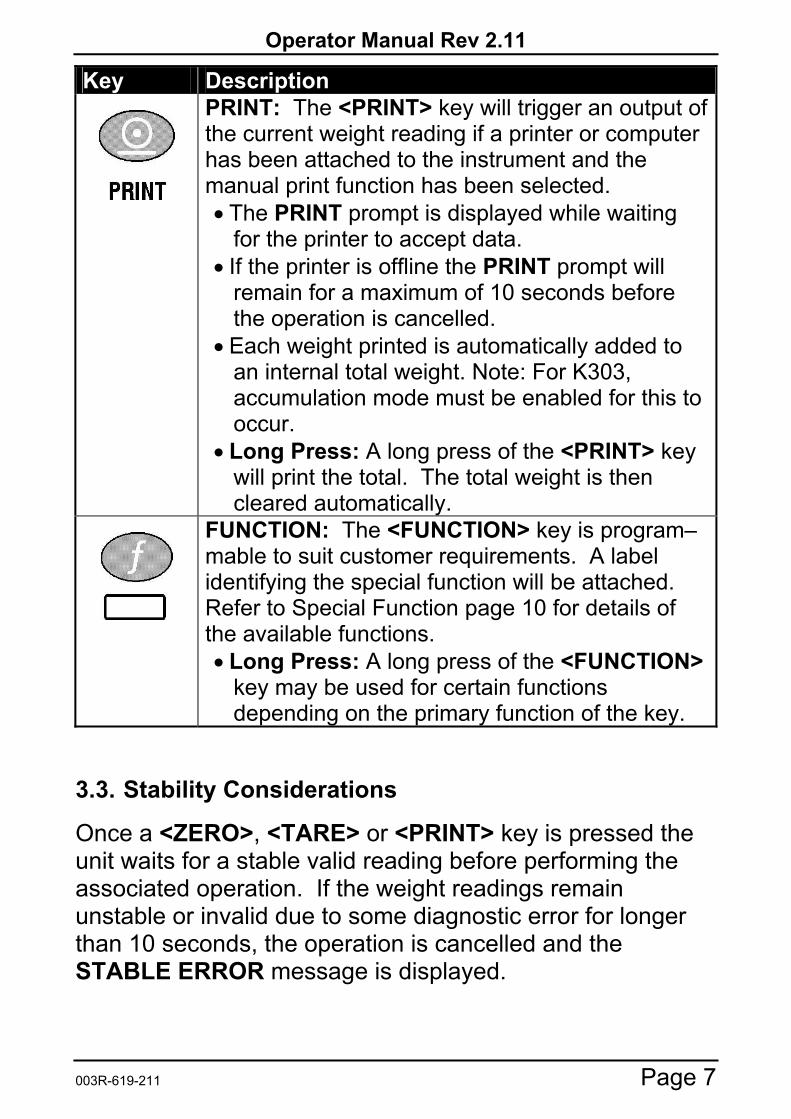
PRINT: The <PRINT> key will trigger an output of the current weight reading if a printer or computer has been attached to the instrument and the manual print function has been selected. • The PRINT prompt is displayed while waiting
for the printer to accept data. • If the printer is offline the PRINT prompt will
remain for a maximum of 10 seconds before the operation is cancelled.
• Each weight printed is automatically added to an internal total weight. Note: For K303, accumulation mode must be enabled for this to occur.
• Long Press: A long press of the <PRINT> key will print the total. The total weight is then cleared automatically.
FUNCTION: The <FUNCTION> key is program–mable to suit customer requirements. A label identifying the special function will be attached. Refer to Special Function page 10 for details of the available functions. • Long Press: A long press of the <FUNCTION>
key may be used for certain functions depending on the primary function of the key.
3.3. Stability Considerations
Once a <ZERO>, <TARE> or <PRINT> key is pressed the unit waits for a stable valid reading before performing the associated operation. If the weight readings remain unstable or invalid due to some diagnostic error for longer than 10 seconds, the operation is cancelled and the STABLE ERROR message is displayed.

Operator Manual Rev 2.11
Page 8 003R-619-211
3.4. Annunciators Symbol Name Description
ZERO Visible when the gross reading is within ± ¼ of a division of true zero.
NET Visible when the displayed reading represents Net weight.
MOTION Visible when the displayed reading is not stable.
Output 1 Visible when the output 1 is active and dual range is not enabled. 1
RANGE 1 Visible when dual range is enabled and range 1 is active. (K305 only.)
Output 2 Visible when the output 2 is active and dual range is not enabled. 2
RANGE 2 Visible when dual range is enabled and range 2 is active. (K305 only.)
ZERO BAND
Visible when the displayed weight is within the zero 'dead' band setting. (The zero band symbol shows near the top right corner of the display.)
HOLD Visible when the displayed reading is held.
LOW BATTERY
Visible when battery voltage is too low and batteries need replacing or recharging. (The low battery symbol shows in the top right corner of the display.)

Operator Manual Rev 2.11
003R-619-211 Page 9
4. Basic Weighing 4.1. Normal Weighing • Ensure instrument is On and Zero annunciator is lit. • Place your item on the weigh platform. • Read the weight display.
4.2. Using Tare • The indicator displays zero with Zero annunciator lit. • Place the container on the weigh platform. • Press the <TARE> key.
• The indicator will show the displayed zero weight and the Net annunciator will be lit.
• Fill the container to the required weight. • Press the <GROSS/NET> key to toggle
between the Net weight and the Gross (total) weight.

Operator Manual Rev 2.11
Page 10 003R-619-211
5. Special Functions 5.1. Testing the Display • Press the <TEST> key to clear the display then
show all segments of the display then clear the display again before returning to normal operation.
5.2. Counting • Place the container on the weigh platform and
press <TARE> if required.
• Place the sample pieces to be counted on the weigh platform.
• Press and hold the <COUNT> key for two seconds. The default number of pieces in the sample will be displayed.
• Use the <GROSS/NET> and <PRINT> keys to alter the number of pieces.
and • Press <COUNT>. The current sample will be
stored against the entered pieces. The letter p (for pieces) displays when in counts display.
• Press the <COUNT> key to toggle between the weight display and the counts display.
• If printing is enabled the sample quantity and weight will be printed.

Operator Manual Rev 2.11
003R-619-211 Page 11
5.3. Units Switching (kg / lb) • Press the <UNITS> key to switch the display
between kilograms and pounds.
• Printing and serial communications will use the units displayed (either lb or kg).
5.4. Hold • Press the <HOLD> key to hold the displayed
weight at its current weight.
• The Hold annunciator will be lit. • Press the <HOLD> key again to release the
weight reading and return the display to normal weighing.
• All printouts that print the displayed weight will use the held weight reading if it is currently being displayed. Note: K303 will not print while a weight is held.
5.5. Peak Hold • Press the <PEAK> key to show the largest
absolute weight, either positive or negative (eg. -30 is larger than 25). The instrument compares the current weight reading with the stored peak and updates the peak reading whenever a larger weight is detected.
• The Hold annunciator will be lit. • Press the <PEAK> key to toggle between the
current weight and the peak weight. • When displaying the peak weight the Hold
annunciator will be lit. • When displaying the peak weight, press and hold
the <PEAK> key for two seconds to clear the peak value and reset back to 0 (zero).

Operator Manual Rev 2.11
Page 12 003R-619-211
• All printouts that print the displayed weight will use the held weight reading if it is currently being displayed. Note: K303 will not print while a weight is held.
5.6. Live Weighing • Press and hold the <LIVE WT> key to switch
between normal weighing and live weight mode. The display will briefly show NORMAL or LIVE.WT.
• Note: During normal weighing, this key operates exactly like a manual <HOLD> key.
• When in Live-Weight mode and while the Net weight is within the zero 'dead' band, the instrument shows the current weight.
• Press the <TARE> or <ZERO> key to clear any residual weight and return the scale to the zero state. or
• Move the animal on to the weigh platform. • Once the weight moves outside the zero 'dead' band the
instrument begins to calculate a long-term average that compensates for any movement in the mass. The instrument flashes the Hold annunciator and shows the current average value.
• The Hold annunciator is steady when the final sample weight is shown on the display.
• Press the <LIVE.WT> key to force the sample to be recalculated.
• Once the animal is removed, the instrument automatically clears the previous reading ready for the next animal.

Operator Manual Rev 2.11
003R-619-211 Page 13
5.7. Showing Totals • The <PRINT> key is used not only to print the
current weight but also to add that weight to the current total.
• When the <TOTAL> key is pressed, the indicator displays COUNT followed by the number of items in the total.
• After this the indicator displays TOTAL followed by the current total weight.
• If the total weight is too large to display in six digits, the weight is shown in two sections labelled with the upper six digits displayed before the lower six digits.
• Press and hold the <PRINT> key to cause the total accumulated weight to be printed and then cleared.
5.8. High Resolution (K302, K305) • When the <HI RES> key is pressed, the
indicator shows a high resolution (x 10) on the display for a period of 5 seconds before reverting to the normal weight display.
• While the high resolution is displayed the units annunciator flashes.
• Printing is inhibited while the high resolution is displayed.
Operator Manual Rev 2.11
Page 14 003R-619-211
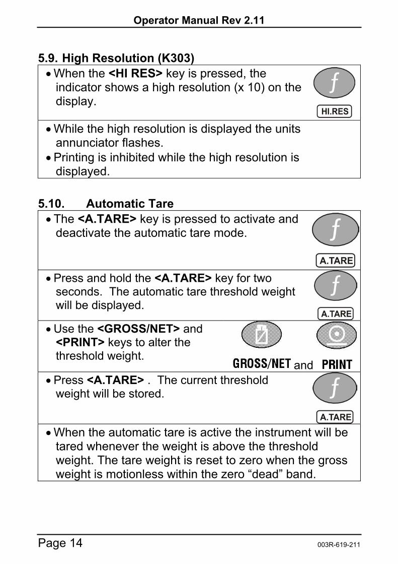
5.9. High Resolution (K303) • When the <HI RES> key is pressed, the
indicator shows a high resolution (x 10) on the display.
• While the high resolution is displayed the units annunciator flashes.
• Printing is inhibited while the high resolution is displayed.
5.10. Automatic Tare • The <A.TARE> key is pressed to activate and
deactivate the automatic tare mode.
• Press and hold the <A.TARE> key for two seconds. The automatic tare threshold weight will be displayed.
• Use the <GROSS/NET> and <PRINT> keys to alter the threshold weight.
and • Press <A.TARE> . The current threshold
weight will be stored.
• When the automatic tare is active the instrument will be tared whenever the weight is above the threshold weight. The tare weight is reset to zero when the gross weight is motionless within the zero “dead” band.

Operator Manual Rev 2.11
003R-619-211 Page 15
5.11. SetPoint • When the <Set.Pt> key is pressed the display
will briefly show each of the following: • SETPT.1 • The target weight for setpoint 1. • SETPT.2 • The target weight for setpoint 2. • Press and hold the < Set.Pt > key for two
seconds SETPT.1 will be displayed followed by the target 1 weight for editing.
• Use the <GROSS/NET> and <PRINT> keys to alter the setpoint 1 target weight.
and • Press < Set.Pt >. The setpoint 1 target weight
will be stored. SETPT.2 will be displayed followed by the target 2 weight for editing.
• Use the <GROSS/NET> and <PRINT> keys to alter the setpoint 2 target weight.
and • Press < Set.Pt >. The setpoint 2 target weight
will be stored. And the display will return to normal.
• Note: For the setpoint thresholds to have any effect the relivant setpoint options need to be selected in the setpoint menu.
Operator Manual Rev 2.11
Page 16 003R-619-211
6. Error Messages
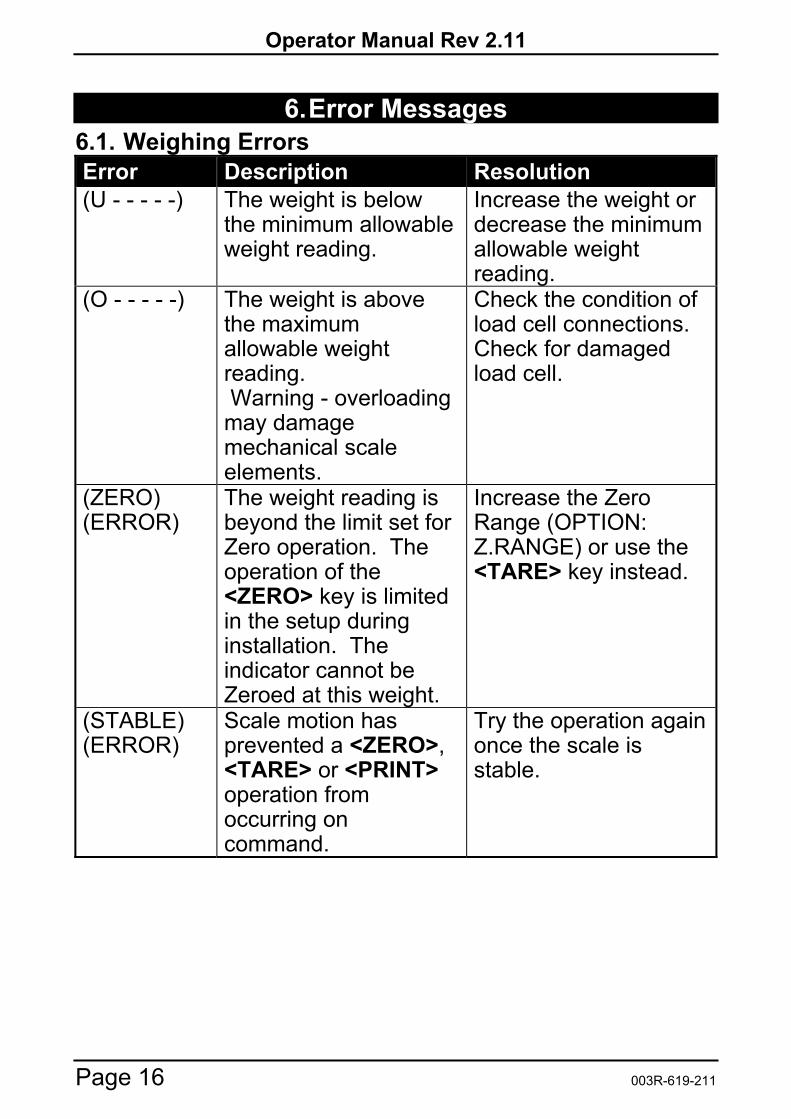
6.1. Weighing Errors Error Description Resolution (U - - - - -) The weight is below
the minimum allowable weight reading.
Increase the weight or decrease the minimum allowable weight reading.
(O - - - - -) The weight is above the maximum allowable weight reading. Warning - overloading may damage mechanical scale elements.
Check the condition of load cell connections. Check for damaged load cell.
(ZERO) (ERROR)
The weight reading is beyond the limit set for Zero operation. The operation of the <ZERO> key is limited in the setup during installation. The indicator cannot be Zeroed at this weight.
Increase the Zero Range (OPTION: Z.RANGE) or use the <TARE> key instead.
(STABLE) (ERROR)
Scale motion has prevented a <ZERO>, <TARE> or <PRINT> operation from occurring on command.
Try the operation again once the scale is stable.

Operator Manual Rev 2.11
003R-619-211 Page 17
6.2. Setup and Calibration Errors
Error Description Resolution The instrument may be in Safe Setup and an item that needs Full Setup has been selected for editing.
Access Full Setup to edit the item.
(ENTRY) (DENIED)
When accessing setup, more than three attempts have been made with the incorrect passcode.
Turn the instrument off. When the instrument is turned back on, enter the correct passcode to access setup.
(LIN.PT) (LO)
An attempt has been made to place a linearisation point below zero.
Incorrect linearisation point entered (must be between zero and full scale).
(PT.TOO) (CLOSE)
An attempt has been made to place a calibration point too close to an existing calibration point.
Re-enter the calibration point. Points must be spaced by at least 2% of full scale from each other.
(RES) (LO)
The scale build is configured for less than 100 graduations.
Check the resolution (count-by) and capacity settings.
(RES) (HIGH)
The scale build is configured for more than 30,000 graduations. (K303: 60,000 graduations)
Check the resolution (count-by) and capacity settings.
(SPAN) (LO)
The load cell signal range (span) is too small for these settings.
Incorrect span weight entered (must be between zero and full scale). Scale wiring incorrect. Wrong load cell capacity (too large). Wrong or no calibration weight added to scale.
(SPAN) (HI)
The load cell signal range (span) is too large for these settings.
Incorrect span weight entered (must be between zero and full scale). Scale wiring incorrect. Load cell capacity too small for application.
(ZERO) (LO)
An attempt has been made to calibrate zero below -2mV/V.
Scale wiring incorrect.
(ZERO) (HI)
An attempt has been made to calibrate zero above +2mV/V.
Remove all weight from scale. Scale wiring incorrect.

Operator Manual Rev 2.11
Page 18 003R-619-211
6.3. Diagnostic Errors
• Check: Service personnel can check this item on site. • Return for Service: The instrument must be returned to the
manufacturer for factory service. Error Description Resolution (E0001) The power supply voltage is too
low. Check supply
(E0002) The power supply voltage is too high.
Check scale / cables
(E0010) The temperature is outside of allowable limits.
Check location
(E0020) Scale build is incorrect. The number of graduations has been set too low or too high.
Fix up scale build
(E0100) The digital setup information has been lost.
Re-enter setup
(E0200) The calibration information has been lost.
Re-calibrate
(E0300) All setup information has been lost
Enter setup and calibrate
(E0400) The factory information has been lost.
Return for Service
(E0800) The EEPROM memory storage chip has failed
Return for Service
(E2000) ADC Out of Range Error. This may be caused from a broken load cell cable.
Check BUILD:CABLE setting. Check load cell cable, wiring, etc.
(E4000) The battery backed RAM data has lost data.
Re-enter setup
(E8000) The FLASH program memory is incorrect
Return for Service
The E type error messages are additive. For example if instrument is running off batteries and the temperature drops, the battery voltage may be too low. The resulting error messages will be E0011 (0001 + 0010). The numbers add in hexadecimal as follows:
1 - 2 - 3 - 4 - 5 - 6 - 7 - 8 - 9 - A - B - C - D - E - F (For example, 2 + 4 = 6, or 4 + 8 = C

Operator Manual Rev 2.11
003R-619-211 Page 19
Notes:

Operator Manual Rev 2.11
Page 20 003R-619-211
Notes:

Notes: