Embed Size (px)
Citation preview
19th World Conference on Non-Destructive Testing 2016
1 License: http://creativecommons.org/licenses/by-nd/3.0/
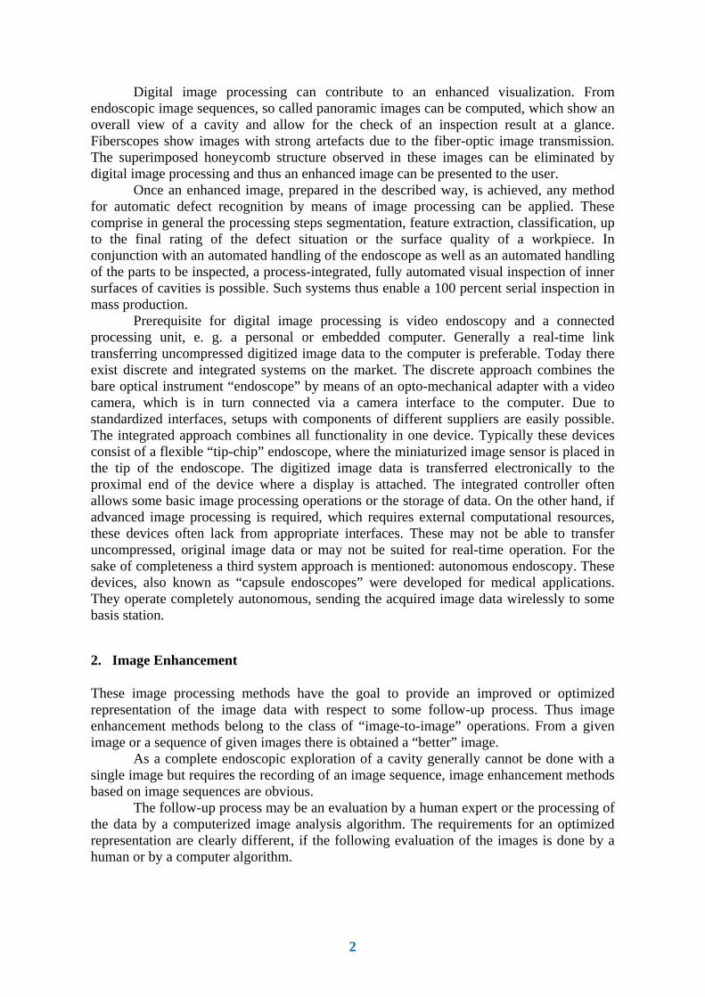
Digital Image Processing for the Automation of NDT by Means of Endoscopy
Klaus SPINNLER 1, Tobias BERGEN 2, Jan SANDVOSS 1, Thomas WITTENBERG 2 1 Fraunhofer IIS Entwicklungszentrum Röntgentechnik (EZRT), Fürth, Germany
2 Fraunhofer Institut Integrierte Schaltungen (IIS), Erlangen, Germany
Contact e-mail: {klaus.spinnler, tobias.bergen, thomas.wittenberg}@iis.fraunhofer.de
Abstract. Visual inspection is one of the most widely used NDT-methods. Endoscopes are an important tool for the inspection of difficult to access surfaces inside the work pieces under test. The application of video technology enables the ergonomic visualization of the inspection. The application of digital technology enables even more: Digital image processing can contribute to an enhanced visualization. From endoscopic image sequences, so called panoramic images can be computed, which show an overall view of a cavity and allow for the check of an inspection result at a glance. By means of filtering and masking of the recorded images, poorly exposed image portions, e. g. underexposed or overexposed, can be discarded. Thus overall views with nearly homogeneous illumination level can be presented to the user. Fiberscopes show images with strong artefacts due to the fiber-optic image transmission. The superimposed honeycomb structure observed in these images can be eliminated by digital image processing and thus an enhanced image can be presented to the user. Once an enhanced image, prepared in the described way, is achieved, any method for automatic defect recognition by means of image processing can be applied. These comprise in general the processing steps segmentation, feature extraction, classification, up to the final rating of the defect situation or the surface quality of a workpiece. In conjunction with data of the movement of the endoscope, also a 3D reconstruction of the cavity under inspection is possible. Such algorithms are based on the principle of “shape-from-motion” or “shape-from-polarisation” for example. Typical applications are automated inspections of hydraulic components with bore diameters in the range of 2 – 20 mm in automotive industry. By means of an automated materials handling and positioning technology a fully automated surface inspection of bore holes and cavities in workpieces made from metal or plastics can be done. Thus a 100-percent, process-integrated routine test with high quantities and short cycle times is possible.
1. Introduction
Visual inspection is one of the most widely used NDT-methods. Endoscopes are an important tool for the inspection of difficult to access surfaces inside the work pieces under test. The application of video technology enables the ergonomic visualization of the inspection. The application of digital image processing technology enables even more:
More info about this article: http://ndt.net/?id=19305
2
Digital image processing can contribute to an enhanced visualization. From endoscopic image sequences, so called panoramic images can be computed, which show an overall view of a cavity and allow for the check of an inspection result at a glance. Fiberscopes show images with strong artefacts due to the fiber-optic image transmission. The superimposed honeycomb structure observed in these images can be eliminated by digital image processing and thus an enhanced image can be presented to the user.
Once an enhanced image, prepared in the described way, is achieved, any method for automatic defect recognition by means of image processing can be applied. These comprise in general the processing steps segmentation, feature extraction, classification, up to the final rating of the defect situation or the surface quality of a workpiece. In conjunction with an automated handling of the endoscope as well as an automated handling of the parts to be inspected, a process-integrated, fully automated visual inspection of inner surfaces of cavities is possible. Such systems thus enable a 100 percent serial inspection in mass production.
Prerequisite for digital image processing is video endoscopy and a connected processing unit, e. g. a personal or embedded computer. Generally a real-time link transferring uncompressed digitized image data to the computer is preferable. Today there exist discrete and integrated systems on the market. The discrete approach combines the bare optical instrument “endoscope” by means of an opto-mechanical adapter with a video camera, which is in turn connected via a camera interface to the computer. Due to standardized interfaces, setups with components of different suppliers are easily possible. The integrated approach combines all functionality in one device. Typically these devices consist of a flexible “tip-chip” endoscope, where the miniaturized image sensor is placed in the tip of the endoscope. The digitized image data is transferred electronically to the proximal end of the device where a display is attached. The integrated controller often allows some basic image processing operations or the storage of data. On the other hand, if advanced image processing is required, which requires external computational resources, these devices often lack from appropriate interfaces. These may not be able to transfer uncompressed, original image data or may not be suited for real-time operation. For the sake of completeness a third system approach is mentioned: autonomous endoscopy. These devices, also known as “capsule endoscopes” were developed for medical applications. They operate completely autonomous, sending the acquired image data wirelessly to some basis station.
2. Image Enhancement
These image processing methods have the goal to provide an improved or optimized representation of the image data with respect to some follow-up process. Thus image enhancement methods belong to the class of “image-to-image” operations. From a given image or a sequence of given images there is obtained a “better” image.
As a complete endoscopic exploration of a cavity generally cannot be done with a single image but requires the recording of an image sequence, image enhancement methods based on image sequences are obvious.
The follow-up process may be an evaluation by a human expert or the processing of the data by a computerized image analysis algorithm. The requirements for an optimized representation are clearly different, if the following evaluation of the images is done by a human or by a computer algorithm.
3
2.1 Panoramic Images
From endoscopic image sequences, so called panoramic images can be computed, which show an overall view of a cavity. By means of filtering and masking of the recorded images, poorly exposed image portions, e. g. underexposed, can be discarded. Thus overall views with nearly homogeneous illumination level can be presented to the user.
Due to the general shape of the hollow, different strategies of exploration may result. Whereas a bore hole or a similar tubular structure allows essentially for “moving up” or “moving down” the tube, other cavities may require additionally a lateral movement or tilting and panning of the exploring endoscope. Thus two different algorithmic examples are presented.
2.1.1 Panoramic Images in Cavities
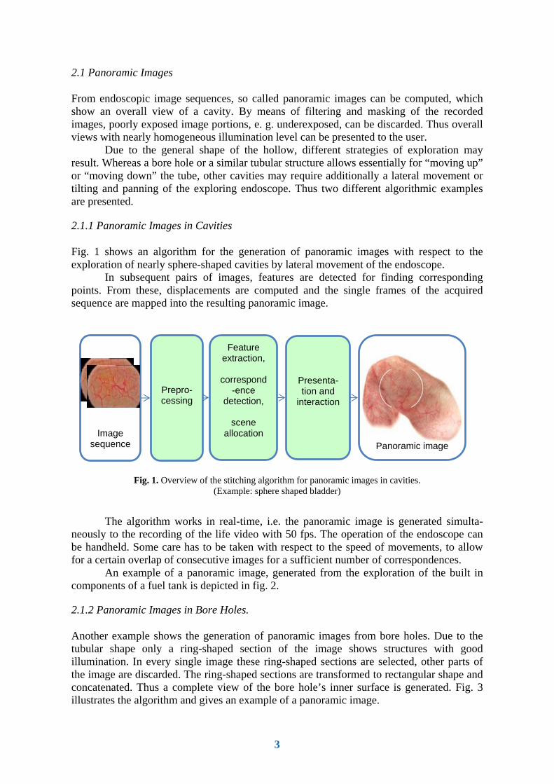
Fig. 1 shows an algorithm for the generation of panoramic images with respect to the exploration of nearly sphere-shaped cavities by lateral movement of the endoscope.
In subsequent pairs of images, features are detected for finding corresponding points. From these, displacements are computed and the single frames of the acquired sequence are mapped into the resulting panoramic image.
Fig. 1. Overview of the stitching algorithm for panoramic images in cavities. (Example: sphere shaped bladder)
The algorithm works in real-time, i.e. the panoramic image is generated simulta-
neously to the recording of the life video with 50 fps. The operation of the endoscope can be handheld. Some care has to be taken with respect to the speed of movements, to allow for a certain overlap of consecutive images for a sufficient number of correspondences.
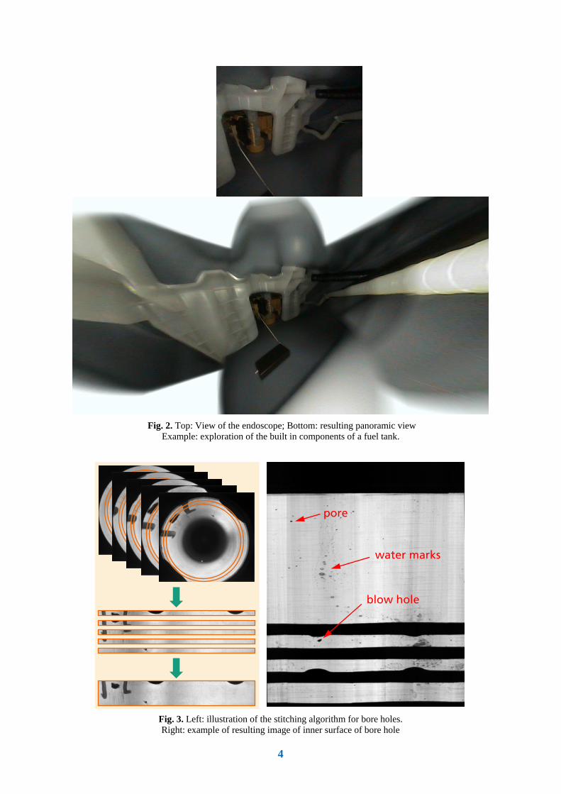
An example of a panoramic image, generated from the exploration of the built in components of a fuel tank is depicted in fig. 2.
2.1.2 Panoramic Images in Bore Holes.
Another example shows the generation of panoramic images from bore holes. Due to the tubular shape only a ring-shaped section of the image shows structures with good illumination. In every single image these ring-shaped sections are selected, other parts of the image are discarded. The ring-shaped sections are transformed to rectangular shape and concatenated. Thus a complete view of the bore hole’s inner surface is generated. Fig. 3 illustrates the algorithm and gives an example of a panoramic image.
Panoramic image
Image sequence
Prepro-cessing
Feature extraction,
correspond
-ence detection,
scene
allocation
Presenta-tion and
interaction
4
Fig. 2. Top: View of the endoscope; Bottom: resulting panoramic view
Example: exploration of the built in components of a fuel tank.
Fig. 3. Left: illustration of the stitching algorithm for bore holes. Right: example of resulting image of inner surface of bore hole
pore
water marks
blow hole

5
3.1 Artifakt Reduction
The poor image quality of the fiber-optic image guide in flexible endoscopes - today widely replaced by videoscopes - motivates another example of image enhancement technology. By means of digital image processing, the superimposed honeycomb structure in images of fiber-optic endoscopes can be eliminated. By combining non-redundant information of several images of an acquired image sequence, even an increase of resolution is possible. (Fig. 4)
Fig. 4. Enhancement of fiber-optic endoscopic images; Top left: original image; Bottom left: enlarged image section; Top Right: eliminated honeycomb structure; Bottom left: super
resolution approach
3. Image Analysis
3.1 Surface Inspection – 2D Analysis
As soon as the described preprocessing steps are successfully applied to the recorded image sequence any image analysis algorithm can be applied to the enhanced panoramic image. After the definition of regions of interest (ROI) according the inspection specification in general the method consists of the basic steps segmentation, feature extraction, and classification.
Fig. 5. Example of 2D analysis: segmentation of blowhole in borehole of cast part. Left: blowhole; Right: visualisation of segmentation algorithm
6
During classification the computed features are evaluated against thresholds given by the inspection specification, thus allowing for an automatic decision, if the inspected part is flawless or faulty and subsequently a sorting of good and bad parts.
Today there exists a huge variety of different algorithms for the above mentioned basic steps. Details can be found e. g. in [1, 2, 3]. As an example, fig. 5 shows the visualized result of a segmentation algorithm applied to the machined surface of a bore hole in an aluminium cast part, showing a blow hole.
3.2 Shape Reconstruction – 3D Analysis
In general, there are inspection criteria in many inspection tasks, which cannot be solved by means of 2D analysis methods but require 3D analysis methods. Testing the correct shape of a workpiece or checking for the depth of a dent or pore are typical examples. This holds true also for applications in the domain of endoscopy. With respect to the bad accessibility there are strong constraints for the size of appropriate devices. Nevertheless there are special endoscopic systems on the market allowing for 3D-measurements. Typical 3D-measurement methods, incorporated in endoscopic systems are laser triangulation or stripe projection methods. These methods require specially designed endoscopic devices.
The following chapters introduce two 3D measurement methods which do not need specially designed endoscopic devices but can be applied in conjunction with most “off-the-shelf” endoscopes.
3.2.1 3D Measurement by Modified Shape-from-Motion Approach (“SfM”)
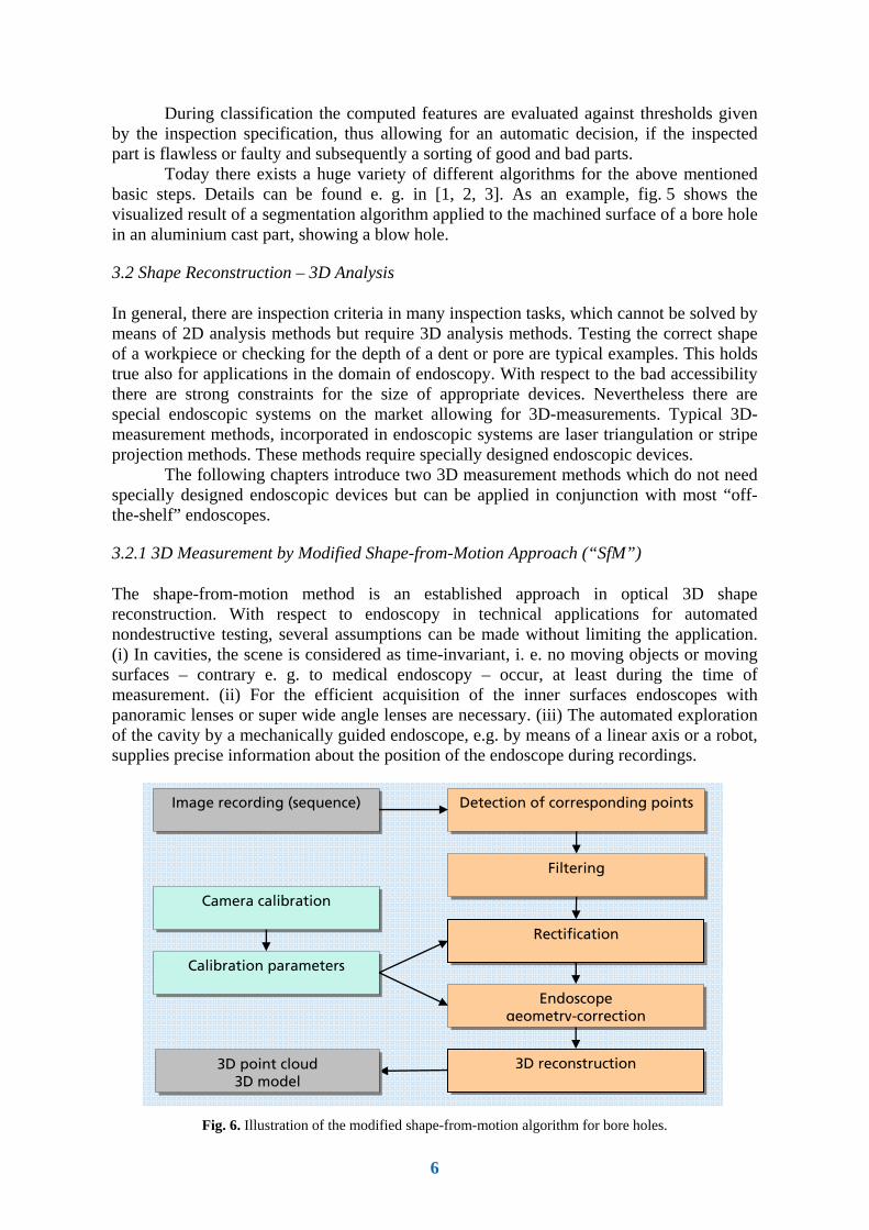
The shape-from-motion method is an established approach in optical 3D shape reconstruction. With respect to endoscopy in technical applications for automated nondestructive testing, several assumptions can be made without limiting the application. (i) In cavities, the scene is considered as time-invariant, i. e. no moving objects or moving surfaces – contrary e. g. to medical endoscopy – occur, at least during the time of measurement. (ii) For the efficient acquisition of the inner surfaces endoscopes with panoramic lenses or super wide angle lenses are necessary. (iii) The automated exploration of the cavity by a mechanically guided endoscope, e.g. by means of a linear axis or a robot, supplies precise information about the position of the endoscope during recordings.
Fig. 6. Illustration of the modified shape-from-motion algorithm for bore holes.
Endoscope geometry-correction
Detection of corresponding points
Filtering
Rectification
Image recording (sequence)
3D reconstruction 3D point cloud 3D model
Calibration parameters
Camera calibration
7
With these assumptions the general shape-from-motion approach is modified for the application of bore hole inspection. An overview of the algorithm is given in fig. 6.
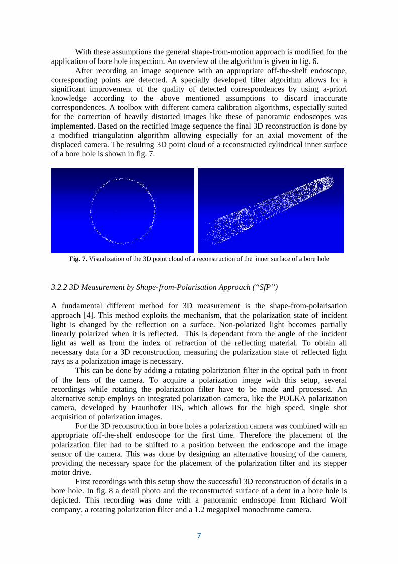
After recording an image sequence with an appropriate off-the-shelf endoscope, corresponding points are detected. A specially developed filter algorithm allows for a significant improvement of the quality of detected correspondences by using a-priori knowledge according to the above mentioned assumptions to discard inaccurate correspondences. A toolbox with different camera calibration algorithms, especially suited for the correction of heavily distorted images like these of panoramic endoscopes was implemented. Based on the rectified image sequence the final 3D reconstruction is done by a modified triangulation algorithm allowing especially for an axial movement of the displaced camera. The resulting 3D point cloud of a reconstructed cylindrical inner surface of a bore hole is shown in fig. 7.
Fig. 7. Visualization of the 3D point cloud of a reconstruction of the inner surface of a bore hole
3.2.2 3D Measurement by Shape-from-Polarisation Approach (“SfP”)
A fundamental different method for 3D measurement is the shape-from-polarisation approach [4]. This method exploits the mechanism, that the polarization state of incident light is changed by the reflection on a surface. Non-polarized light becomes partially linearly polarized when it is reflected. This is dependant from the angle of the incident light as well as from the index of refraction of the reflecting material. To obtain all necessary data for a 3D reconstruction, measuring the polarization state of reflected light rays as a polarization image is necessary.
This can be done by adding a rotating polarization filter in the optical path in front of the lens of the camera. To acquire a polarization image with this setup, several recordings while rotating the polarization filter have to be made and processed. An alternative setup employs an integrated polarization camera, like the POLKA polarization camera, developed by Fraunhofer IIS, which allows for the high speed, single shot acquisition of polarization images.
For the 3D reconstruction in bore holes a polarization camera was combined with an appropriate off-the-shelf endoscope for the first time. Therefore the placement of the polarization filer had to be shifted to a position between the endoscope and the image sensor of the camera. This was done by designing an alternative housing of the camera, providing the necessary space for the placement of the polarization filter and its stepper motor drive.
First recordings with this setup show the successful 3D reconstruction of details in a bore hole. In fig. 8 a detail photo and the reconstructed surface of a dent in a bore hole is depicted. This recording was done with a panoramic endoscope from Richard Wolf company, a rotating polarization filter and a 1.2 megapixel monochrome camera.

8
Fig. 8. 3D reconstruction of a dent (red circle) in a bore hole by shape-from-polarization method
Thus it is expected, that with both setups the use of appropriate off-the-shelf
endoscopes is possible to acquire polarization images or image sequences suited for the 3D reconstruction of inner surfaces in bore holes or cavities.
Further research has to be done for the shape-from-motion and shape-from-polarization method in endoscopy with respect to calibration of the system and the evaluation of achievable accuracy.
References
[1] Jähne, B.; Massen, R.; Nickolay, B.; Scharfenberg, H.: Technische Bildverarbeitung. Maschinelles Sehen, Springer-Verlag, Heidelberg, 1996 (Reprint 2012), ISBN 978-3642648236
[2] Jähne, B.: Digitale Bildverarbeitung und Bildgewinnung. Springer Vieweg, Berlin, 2012. [3] Bauer, N.; Sackewitz, M. (Hrsg.): Fraunhofer Vision-Leitfaden-Reihe zur Bildverarbeitung,
Fraunhofer Verlag, Stuttgart/Erlangen, 2000-2011, ISSN 1618-1565 [4] Rahmann, S.: Inferring 3d scene structure from a single polarization image. In Conference on
Polarization and Color Techniques in Industrial Inspection, volume 3826 of SPIE Proceedings, pages 22-33, 1999.