Embed Size (px)
Citation preview

,- -- --- " -�--,------ --- --,---' ___ ----'_,___ __ _ :c --"._ ,�-----------�..,........--�
Digital Fabrications
Architectural and Material Techniques
Lisa Iwamoto
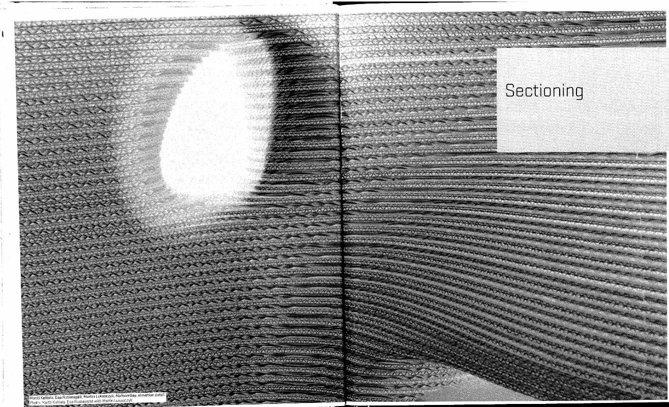
Sectioning
Sectioning
Orthographic projections-that is, plans and sections-are one of the most valuable representational tools architects have at their disposal. They are an indispensable communication and design device. They have also contributed to a prominent digital fabrication method. With computer modeling, deriving sections is no longer a necessarily two-dimensional drawing exercise. In fact, it is no longer an exercise in projection at all but a process of taking cuts through a formed three-dimensional object. As architects increasingly design with complex geometries, using sectioning as a method of taking numerous cross sections through a form has proven time and again an effective and compelling technique. As in conventional construction processes, information is translated from .one format to another to communicate with the builder-only in this case the builder is a machine.
Rather than construct the surface itself, sectioning uses a series of profiles, the edges of which follow lines of surface geometry. The modeling software's sectioning or contouring commands can almost instantaneously cut parallel sections through objects at designated intervals. This effectively streamlines the process of making serialized, parallel sections. Architects have experimented with sectional assemblies as a way to produce both surface and structure.
While it is distinctly within the domain of digital techniques, sectioning has a long history in the construction industry. It is commonly used in airplane and shipbuilding to make the doubly curving surfaces associated with their respective built forms. Objects such as airplane bodies and boat hulls are first defined sectionally as a series of structural ribs, then clad with a surface material. Lofting-the method that determines the shape of the cladding or surface panels by building between curved cross-sectional profiles-is analogous to lofting in digital software. Lofted surfaces can be unrolled into flat pieces or else geometrically redescribed in section as curves along the surface.
010/011
This building technique was adopted in the predigital era by architects such as Le Corbusier. The roof of the chapel at Ronchamp, for examplelikened to an airplane wing by the architect-is designed and built as a series of structural concrete ribs, tied together laterally by crossbeams. A paper model of the roof clearly shows the intentions for the internal construction. The advantages of using this type of hollow construction are clear: it is a lightweight structure that provides accurate edge profiles for a nonuniform shape on which to align and support surface material, in this case thin shells of concrete. In his book Ronchamp, Le Corbusier enumerates the unique constructional makeup in a manner that recalls the makeup of digitally constructed projects: "Seven strong, flat beams, 17 em. thick, all different."l
Another architect who worked almost exclusively with forms that required nonstandard construction was Frederick Kiesler. Indeed he has become a poster child of sorts for protoblob architecture. In the context of digital fabrication, his relevance has less to do with the shapes of his buildings and more to do with his efforts to develop a method for building his "endless" forms. It is not surprising that Kiesler's endeavors in this regard have correlations with digital construction. Although the truly organic form of his Endless House was never realized, he did complete several projects, most notably Peggy Guggenheim's Art of This Century gallery, in 1942. The gallery bespeaks his desire for a sentient architecture that would be responsive to its occupants' mercurial perceptions: the picture frames are suspended from the walls so as to interact with various viewers against a curved backdrop. Study sketches of the curved wall and ceiling reveal sectional ribs that are aestheti�ized to resemble an airplane or other machined framework. The curvature of the wall is consistent along its length, so, unlike the ribs of Le Corbusier's chapel at Ronchamp, these are repetitive. What is similar about these projects is their employment of sectioning for constructional and geometric purposes in the making of curved forms.
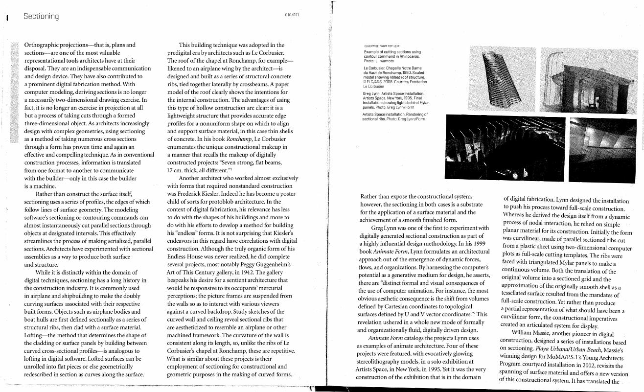
CLOCKWISE FROM TOP LEFT:
Example of cutting sections using contour command in Rhinoceros. Photo: L. Iwamoto
Le Corbusier, Chapelle Notre Dame du Haut de Ronchamp, 1950. Scaled model showing ribbed roof structure. 19 FLC/ARS, 2008. Courtesy Fondation Le Corbusier
Greg Lynn, Artists Space installation, Artists Space, New York, 1995. Final installation showing lights behind Mylar panels. Photo: Greg Lynn/Form
Artists Space installation. Rendering of sectional ribs. Photo: Greg Lynn/Form
Rather than expose the constructional system, however, the sectioning in both cases is a substrate for the application of a surface material and the achievement of a smooth finished form.
Greg Lynn was one of the first to experiment with digitally generated sectional construction as part of a highly influential design methodology. In his 1999 book Animate Form, Lynn formulates an architectural approach out of the emergence of dynamic forces, flows, and organizations. By harnessing the computer's potential as a generative medium for design, he asserts, there are "distinct formal and visual consequences of the use of computer animation. For instance, the most obvious aesthetic consequence is the shift from volumes defined by Cartesian coordinates to topological surfaces defined by U and V vector coordinates:'2 This revelation ushered in a whole new mode of formally and organizationally fluid, digitally driven design.
Animate Form catalogs the projects Lynn uses as examples of animate architecture. Four of these projects were featured, with evocatively glowing stereolithography models, in a solo exhibition at Artists Space, in New York, in 1995. Yet it was the very construction of the exhibition that is in the domain
of digital fabrication. Lynn designed the installation to push his process toward full-scale construction. Whereas he derived the design itself from a dynamic process of nodal interaction, he relied on simple planar material for its construction. Initially the form was curvilinear, made of parallel sectioned ribs cut from a plastic sheet using two-dimensional computer plots as full-scale cutting templates. The ribs were faced with triangulated Mylar panels to make a continuous volume. Both the translation of the original volume into a sectioned grid and the approximation of the originally smooth shell as a tessellated surface resulted from the mandates of full-scale construction. Yet rather than produce a partial representation of what should have been a curvilinear form, the constructional imperatives created an articulated system for display.
William Massie, another pioneer in digital construction, designed a series of installations based on sectioning. Playa Urbana/Urban Beach, Massie's winning design for MoMA/P.S.1's Young Architects Program courtyard installation in 2002, revisits the spanning of surface material and offers a new version of this constructional system. It has translated the

Sectioning
system into laser-cut steel fins threaded with exposed
PVC tubing, creating the effect of diaphanous
surfaces of flowing plastic hair that create shade and
accommodate program. The sensuous lines are a
constructive solution that cumulatively define the
larger surfaces and representationally echo the digital
method that made them. That is, the lines define
the physical surface in the same way that embedded
surface curves, or isoparms, make up a digitally ruled,
or lofted, one. Massie's method coordinates well with
conventional building materials. Standard materials typically come as sheets, so that three-dimensional buildings are made from two-dimensional materials. In the case of sectioning, the constructional techpiques that have emerged include sectional ribbing (as in the projects already described), lamination or parallel stacking, and waffle-grid construction. In the case of parallel stacking, the frequency of the sections required to approximate the increasingly varied surface geometries increases, sometimes resulting in a visual intensification of materiaL By using edge profiles to describe surface through implied visual continuities, architects have
012/013
CLOCKWISE FROM TOP LEFT:
William Massie, Playa Urbana/Urban Beach, MoMA/P.S.1, Queens, New York, 2002. Photo: William Massie
Playa Urbana/Urban Beach. Detail of steel rib. Photo: William Massie
SHoP Architects, Ounescape, 2001. Plot files of cross sections used for construction layout. Photo: SHoP Architects
Ounescape. Installation. Photo: SHoP Architects
taken advantage of sectioning-both to merge and to perceptually elevate the relationship of form with material tectonic.
A good example of this merging and perceptual elevation is Dunescape, the project that won MoMAI P.S.l's Young Architects Program the year before Massie's Playa Urbana/Urban Beach. Designed and built by by SHoP Architects, Dunescape is an architecturalized landscape built completely as a series of parallel, stacked dimensional lumber. While manual labor was required to cut, assemble, and fasten the pieces in the actual construction, the methodology was completely digitally driven. First, the digital model was sectioned at intervals that were established by the given material thickness. The resulting section drawings were then plotted at full scale and used as templates on which to lay out and position each wood piece. Not insignificantly, SHoP used this very same technique to make a scaled model in the digital file submitted for the competition presentation-a convincing testament to this particular technique's fluidity, scalability, and credibility.
The substantial rhetoric that has surrounded digital fabrication toward the streamlining of
r f
CLOCKWISE FROM TOP LEFT:
SHoP Architects, Ounescape, 2001. Final installation at MoMA/P.S.l, Queens, New York. Photo: SHoP Architects
Preston Scott Cohen, House on a Terminal Line, 1997. Laser-cut model. Photo: courtesy Scott Cohen/Cameron Wu
Jakob + MacFarlane, Loewy Bookshop, Paris, 2001 Photo: courtesy Jakob + MacFarlane
Alvaro Siza and Eduardo Souto de Moura, Serpentine Pavilion Gallery, London, 2005. Grid-shell lamella structure. Photo: Pietro Russo
construction practice is certainly warranted. Computerized two-and-a-half- and three-axis cutting tools-such as laser cutters, CNC routers, water-jet and plasma cutters-all work from the same polylines to cut two-dimensional materials. While the scale and thickness and size of material may change, the files used to communicate with the various pieces of equipment work off the same set of profiles. Early adopters made a conceptual leap to bridge digital and physical model making with full-scale construction. The leap has yielded a wealth of compelling and sophisticated architectural explorations that have advanced forms of threedimensional representation and building.
Laser cutters in particular have facilitated the conceptual and practical move from making models to executing full-scale construction. Most laser cutters are small; most typically work with model-making materials such as chipboard, acrylic, and cardboard; and most are easy to use with familiar software such as AutoCAD and Adobe Illustrator. Initially laser cutters were employed by architects for precision model making, as for engraved building facades, structural members, and building details. Later
coupling these machines with the digital-design software that fostered nonstandard form making and came equipped with commands to redescribe those precision forms through serial sections, designers were soon able to envision how sectioning, as a representational method, could become a building technique.
Preston Scott Cohen's House on a Terminal Line
( 1998), for example, conceptually unites ground and house by employing a technique of waffle construction for both. Conceived as an inflected landscape, the project was made by taking the perpendicular intersection of two sets of parallel sections through the whole digital modeL The planes meet at corresponding notches, resulting in a gridded, wafflelike framework. Waffle construction is by no means new: such common items as old-fashioned metal ice trays and fluorescent-light baffles have used intersecting grids for years. Though not ultimately built, this project nevertheless provides insight into how the technique could be used for construction as well. In 2001, the Paris-based firm Jakob + MacFarlane used waffle construction as the foundation for the design and construction of the Loewy Bookshop.
Sectioning
One of the 2005 projects, (Ply)wood Delaminations,
takes the technique of straightforward parallel sectioning as its starting point. Strands of CNCrouted plywood cascade down the multistory atrium at Georgia Tech's College of Architecture building, splitting off at intermediate floors and at the ground floor to make seating. Where projects like Mafoombey
use consecutive stacking to provide a solid structure, (Ply)wood Delaminations widely spaces the largely vertical ribs to make a porous surface. The constructive challenge is to maintain the continuity of a large surface that is composed of short, separate pieces. For the most part, the ribs are kept at an even distance by steel rods, threaded through precut holes to regulate the spacing. The pliability of wood and the natural tendency of long strips of material to deflect are celebrated toward the bottom of the installation, where the members are pinched together to create an informal array of elongated eye-shaped openings. These add a new dimension to the overall structure at a scale between the material part and the overall form. A Change of State, a project completed the following year under Tehrani, extends the dialogue of flexible materials and digital construction. This design literally moves from a stacked, striated condition at one end to a loose organization of pillowing strips at the other, using the inherent flexibility of plastic to achieve the formal effect.
Digital Weave, an installation designed and built in 2004 by my own graduate students at the University of California, Berkeley, similarly adapted a sectional methodology to a pliable material. The design was begun by making a simple digital model that was sectioned in a radial fashion into vertical ribs. The rib profiles were then refined to correspond to full-scale construction prototypes. Early in the design process, mock-ups of collapsible systems were made to test constructability and structural stability. The accordion -like structure was then made by slicing each rib longitudinally with dashed cuts and pulling it apart in an alternating rhythm. The final design uses clear acrylic compression rods to expand the ribs and give shape to the overall volume. The ribs are held
016/017
in place through compression and friction and are easily removed for demounting and transportation. Although the students sought geometric alliances between the digital profiles and full-scale mock-ups, the end product was ultimately the result of allowing material deformations to shape the form.
In negotiating constructive exigencies, the project illustrates the adoption of now well-established steps for translating sectional cuts into a material system. Because the sectional cuts are not parallel to one another, the ribs are first rotated, moved onto a consistent plane, and consecutively labeled. Unlike the spacing of the ribs in Mafoombey, the wide spacing of the ribs in Digital Weave results in each rib's being significantly different from the next. The ribs are attached with rivets at connections that alternate between the inside and outside edges, demanding that each match its neighbor along one side. Therefore, each rib was redrawn to have a unique profile that
slightly reshaped the overall form. Students worked in AutoCAD to refine the rib geometries, to introduce the internal football-shaped holes that allowed for the ribs to spread, and to draw all the rivet holes. The ribs were then laid on four-by-eight-foot templates to match the corrugated plastic sheet material and fabricated using a CNC water-jet cutter. The subsequent assembly proceeded rapidly as each rib came off the water-jet cutter, ready to be riveted together in groups of ten for easy transportation and breakdown. Finally, the ribs that had been slipped into the slots in the plywood floor were expanded using the compression rods and then were bolted together on-site.
The projects in this chapter demonstrate the ample diversity of sectioning as a construction technique. There is an eloquent simplicity to the stacked, layered, and gridded tectonic that opens the door to wide constructional interpretation. Ultimately, it is the defamiliarization of both method and material that allows each project to transcend the linear translation from digital to physical sectioning. The intermediary calibration is what ensures that the architects have virtually limitless possibilities for design.
r "� .... ' ..... '" "{ i;
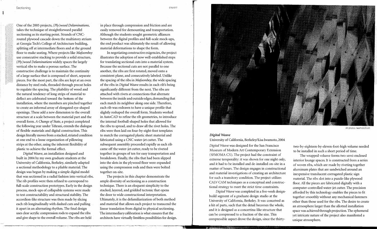
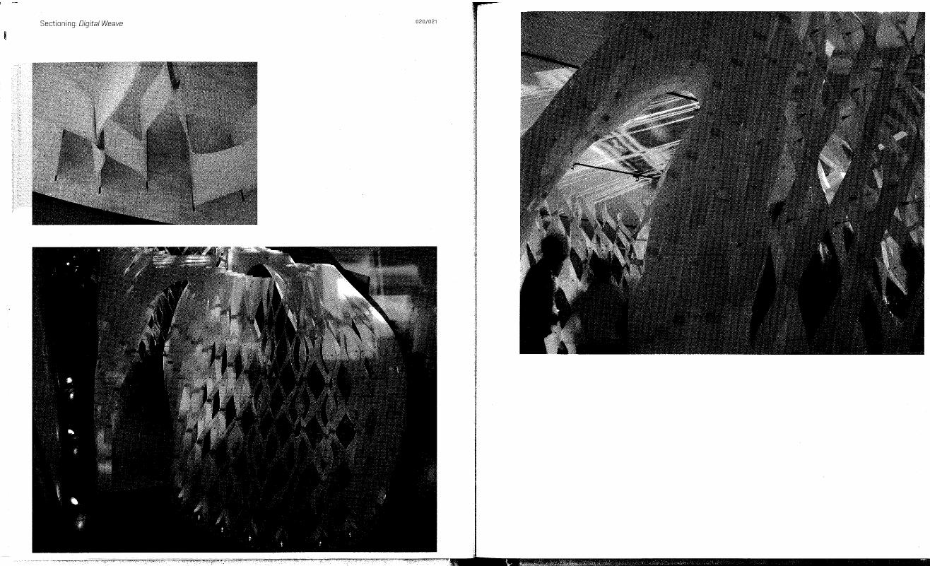
Digital Weave University of California, Berkeley/Lisa Iwamoto, 2004
Digital Weave was designed for the San Francisco Museum of Modern Art Contemporary Extension (SFMOMA CX). The project had the constraint of extreme temporality: it was shown for one night only, and it had to be installed and de-installed on-site in a matter of hours. The design engages in constructional and material investigations of creating an architecture for such a transitory condition. The project utilizes CADI CAM techniques as a conceptual and constructional strategy to meet the strict time constraints.
Digital Weave was completed in a five-week designbuild segment of a graduate design studio at the University of California, Berkeley. It was conceived as a kit of parts, such that the detail becomes the whole, and it is designed as a concertina-like structure that can be compressed to a fraction of the size. This compressible aspect drove the design, since the thirty-
All photos: Iwamoto Scott
two-by-eighteen-by-eleven-foot-high volume needed to be installed in such a short period of time.
The wrapped volume forms two semi-enclosed interior lounge spaces. It is constructed from a series of woven ribs, which are made by riveting together aluminum plates that are sandwiched around an inexpensive translucent corrugated plastic sign material. The ribs slot into a puzzle-like plywood floor. All the pieces are fabricated digitally with a computer-controlled water-jet cutter. The precision afforded by this technology enables the pieces to fit together smoothly without any mechanical fasteners other than those used for the ribs. The desire to create an atmosphere larger than the allotted installation space was achieved through projection. The ephemeral yet intricate nature of the project also manifested a unique atmosphere.
Sectioning: Digital Weave
====- =====::= ------ ------------------- . �
-----: �/ .::<::
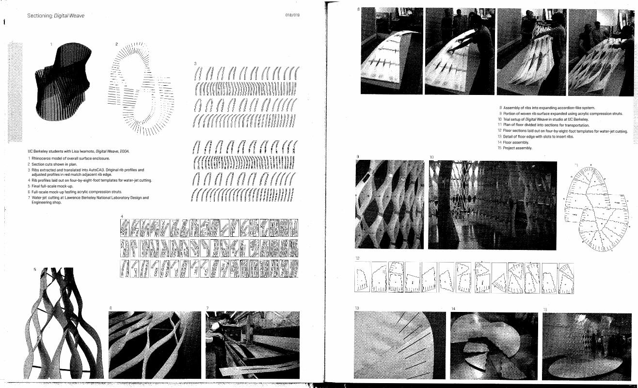
�/r\ �� \\\'>'� UC Berkeley students with Lisa Iwamoto, Digital Weave, 2004.
1 Rhinoceros model of overall surface enclosure.
2 Section cuts shown in plan. .
AutoCAO. Original rib profiles and 3 Ribs extracte? an.d transla��� I
���acent rib edge. adjusted profiles m red ma .J
ht-foot templates for water-jet cutting. 4 Rib profiles laid out on four-by-elg
5 Final full-scale mock-Up. .
t tin acrylic compressIOn struts. 6 Full-scale mock-Up es g
B keley National Laboratory Design and 7 Water-jet cutting at Lawrence er Engineering shop.
018/019
B Assembly of ribs into expanding accordion-like system. .
t t 9 Portion of woven rib surface expanded using acrylic compressIOn s ru s.
10 Trial setup of Digital Weave in studio at UC Berkel.ey.
11 Plan of floor divided into sections for transportation. . tt' .
b .
ht-foot templates for water-Jet cu mg. 12 Floor sections laid out on four- y-elg
13 Detail of floor edge with slots to insert ribs.
14 Floor assembly.
15 Project assembly.
Sectioning: Digital Weave 020/021
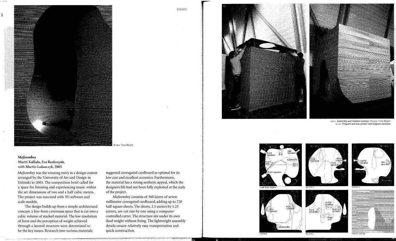
Mafoombey Martti Kalliala, Esa Ruskeepaa, with Martin Lukasczyk, 2005 Mafoombey was the winning entry in a design contest arranged by the University of Art and Design in Helsinki in 2005. The competition brief called for a space for listening and experiencing music within the set dimensions of two and a half cubic meters. The project was executed with 3D software and scale models.
The design builds up from a simple architectural concept: a free-form cavernous space that is cut into a cubic volume of stacked material. The low resolution of form and the perception of weight achieved through a layered structure were determined to be the key issues. Research into various materials
022/023
Photo: Timo Wright
suggested corrugated cardboard as optimal for its low cost and excellent acoustics. Furthermore, the material has a strong aesthetic appeal, which the designers felt had not been fully exploited at the scale of the project.
Mafoombey consists of 360 layers of sevenmillimeter corrugated cardboard, adding up to 720 half-square sheets. The sheets, 2.5 meters by 1.25 meters, are cut one by one using a computercontrolled cutter. The structure sits under its own dead weight without fixing. The lightweight assembly details ensure relatively easy transportation and quick construction.
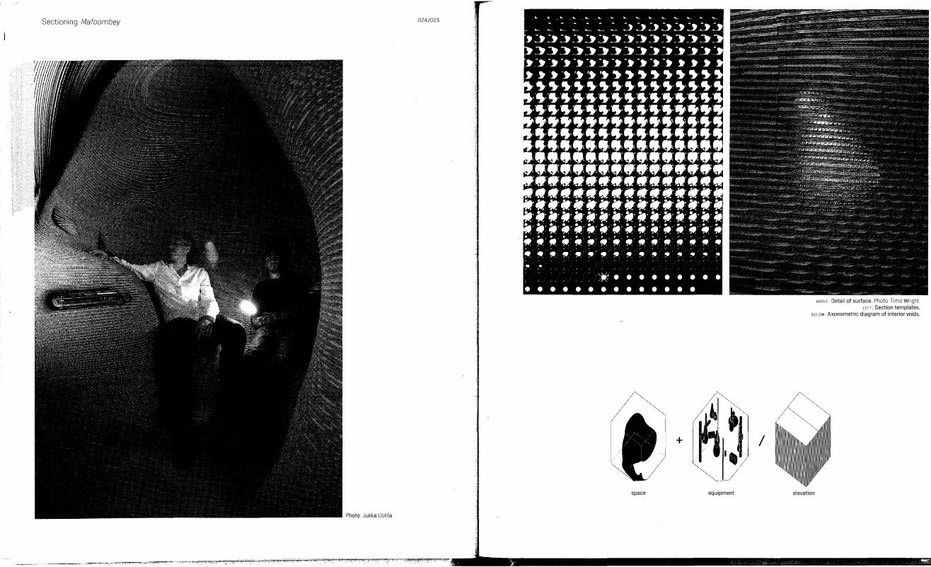
ABOVE: Assembly and finished exterior. Photos: Timo Wright BELOW: Program and equipment void diagram sections.
Sectioning: /v1afoombey 024/025
+
space
Photo: Jukka Uotila
/
equipment
ABOVE: Detail of surface. Photo: Timo Wright LEFT: Section templates.
BELOW: Axonometric diagram of interior voids.
elevation
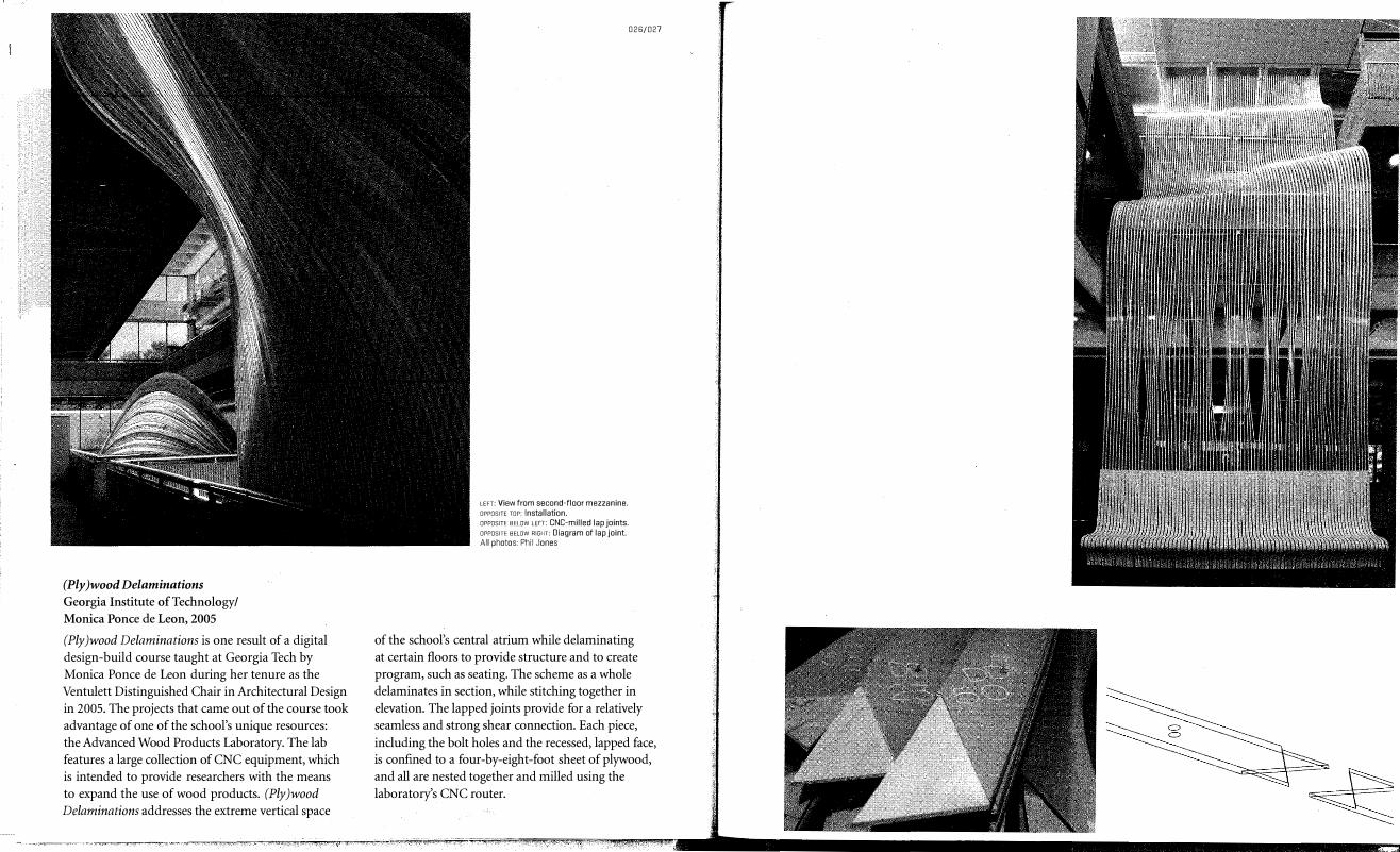
(Ply)wood Delaminations Georgia Institute of Technology/ Monica Ponce de Leon, 2005 (Ply)wood Delaminations is one result of a digital design-build course taught at Georgia Tech by Monica Ponce de Leon during her tenure as the Ventulett Distinguished Chair in Architectural Design in 2005. The projects that came out of the course took advantage of one of the school's unique resources: the Advanced Wood Products Laboratory. The lab features a large collection of CNC equipment, which is intended to provide researchers with the means to expand the use of wood products. (Ply) wood
Delaminations addresses the extreme vertical space
026/027
LEFT: View from second-floor mezzanine. OPPOSITE TOP: Installation. OPPOSITE BELOW LEFT: CNC-milled lap joints. OPPOSITE BELOW RIGHT: Diagram of lap joint. All photos: Phil Jones
of the school's central atrium while delaminating at certain floors to provide structure and to create program, such as seating. The scheme as a whole delaminates in section, while stitching together in elevation. The lapped joints provide for a relatively seamless and strong shear connection. Each piece, including the bolt holes and the recessed, lapped face, is confined to a four-by-eight-foot sheet of plywood, and all are nested together and milled using the laboratory's CNC router.