Embed Size (px)
Citation preview

Digital Design LaboratoryDr. Oniga István
University of Debrecen, Faculty of Informatics
This work was supported by the construction EFOP-3.4.3-16-2016-00021.The project was supported by the European Union, co-financed by the European Social Fund.
4. Laboratory assignments• Encoder circuits• Decoding circuits• Multiplexers
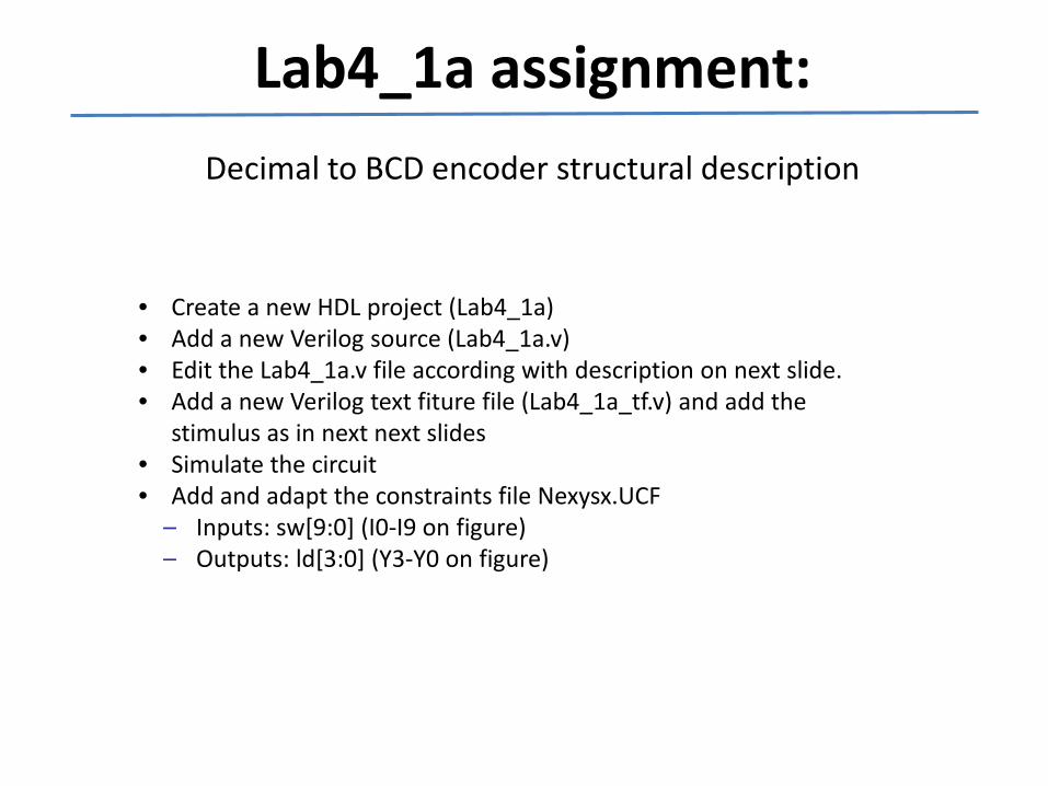
Lab4_1a assignment:Decimal to BCD encoder structural description
• Create a new HDL project (Lab4_1a)• Add a new Verilog source (Lab4_1a.v)• Edit the Lab4_1a.v file according with description on next slide.• Add a new Verilog text fiture file (Lab4_1a_tf.v) and add the
stimulus as in next next slides• Simulate the circuit• Add and adapt the constraints file Nexysx.UCF
– Inputs: sw[9:0] (I0-I9 on figure)– Outputs: ld[3:0] (Y3-Y0 on figure)
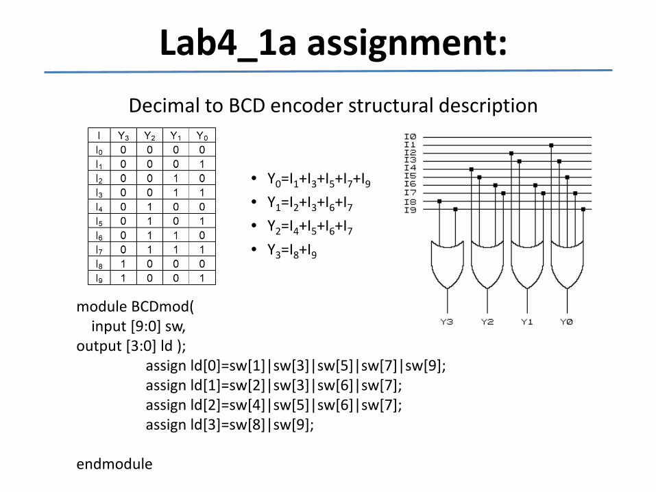
Lab4_1a assignment:Decimal to BCD encoder structural description
module BCDmod(input [9:0] sw,
output [3:0] ld );assign ld[0]=sw[1]|sw[3]|sw[5]|sw[7]|sw[9];assign ld[1]=sw[2]|sw[3]|sw[6]|sw[7];assign ld[2]=sw[4]|sw[5]|sw[6]|sw[7];assign ld[3]=sw[8]|sw[9];
endmodule
• Y0=I1+I3+I5+I7+I9
• Y1=I2+I3+I6+I7
• Y2=I4+I5+I6+I7
• Y3=I8+I9
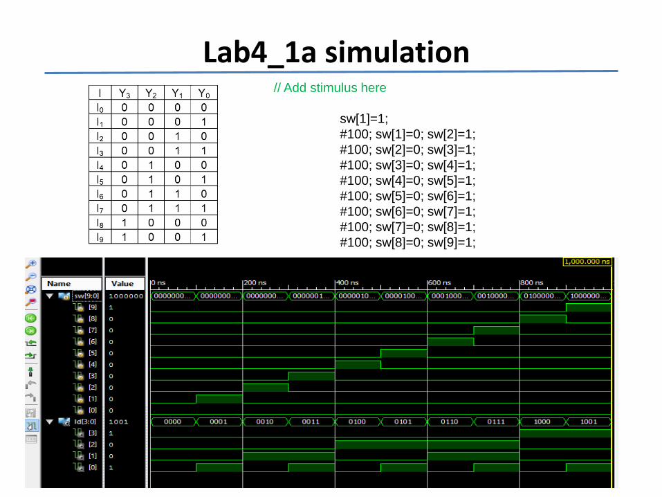
Lab4_1a simulation// Add stimulus here
sw[1]=1;#100; sw[1]=0; sw[2]=1;#100; sw[2]=0; sw[3]=1;#100; sw[3]=0; sw[4]=1;#100; sw[4]=0; sw[5]=1;#100; sw[5]=0; sw[6]=1;#100; sw[6]=0; sw[7]=1;#100; sw[7]=0; sw[8]=1;#100; sw[8]=0; sw[9]=1;
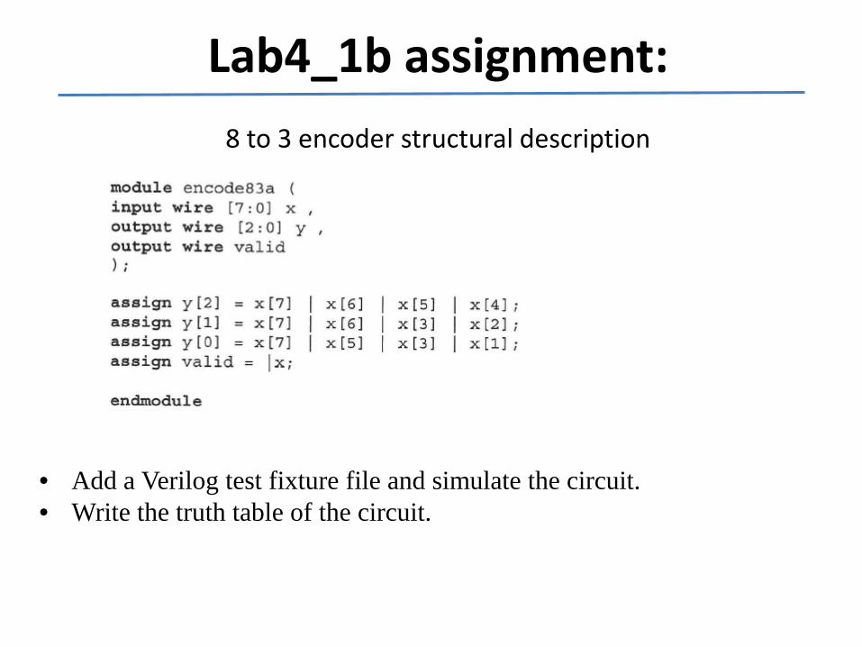
Lab4_1b assignment:8 to 3 encoder structural description
• Add a Verilog test fixture file and simulate the circuit.• Write the truth table of the circuit.
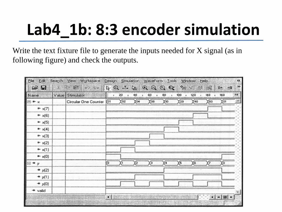
Lab4_1b: 8:3 encoder simulationWrite the text fixture file to generate the inputs needed for X signal (as in following figure) and check the outputs.
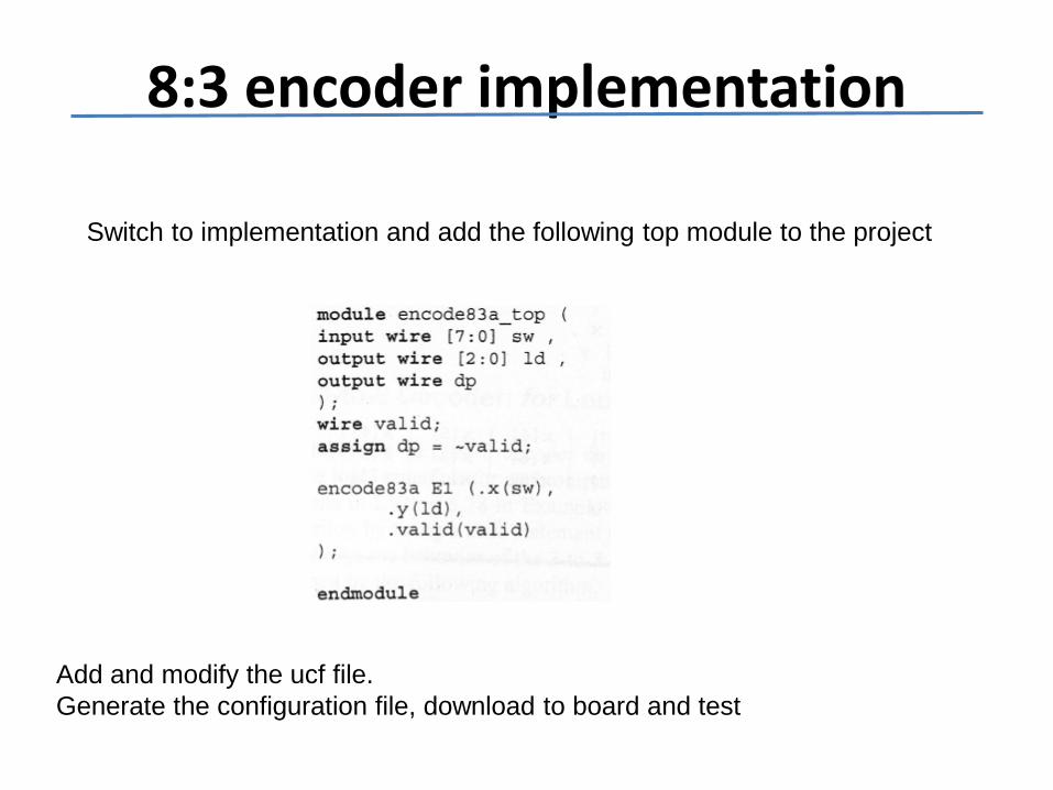
8:3 encoder implementation
Add and modify the ucf file.Generate the configuration file, download to board and test
Switch to implementation and add the following top module to the project
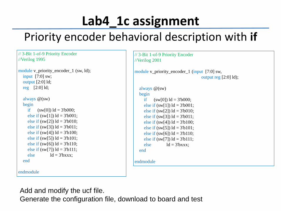
Lab4_1c assignmentPriority encoder behavioral description with if
// 3-Bit 1-of-9 Priority Encoder//Verilog 1995
module v_priority_encoder_1 (sw, ld);input [7:0] sw;output [2:0] ld;reg [2:0] ld;
always @(sw)begin
if (sw[0]) ld = 3'b000;else if (sw[1]) ld = 3'b001;else if (sw[2]) ld = 3'b010;else if (sw[3]) ld = 3'b011;else if (sw[4]) ld = 3'b100;else if (sw[5]) ld = 3'b101;else if (sw[6]) ld = 3'b110;else if (sw[7]) ld = 3'b111;else ld = 3'bxxx;
end
endmodule
// 3-Bit 1-of-9 Priority Encoder//Verilog 2001
module v_priority_encoder_1 (input [7:0] sw, output reg [2:0] ld);
always @(sw)begin
if (sw[0]) ld = 3'b000;else if (sw[1]) ld = 3'b001;else if (sw[2]) ld = 3'b010;else if (sw[3]) ld = 3'b011;else if (sw[4]) ld = 3'b100;else if (sw[5]) ld = 3'b101;else if (sw[6]) ld = 3'b110;else if (sw[7]) ld = 3'b111;else ld = 3'bxxx;
end
endmodule
Add and modify the ucf file.Generate the configuration file, download to board and test
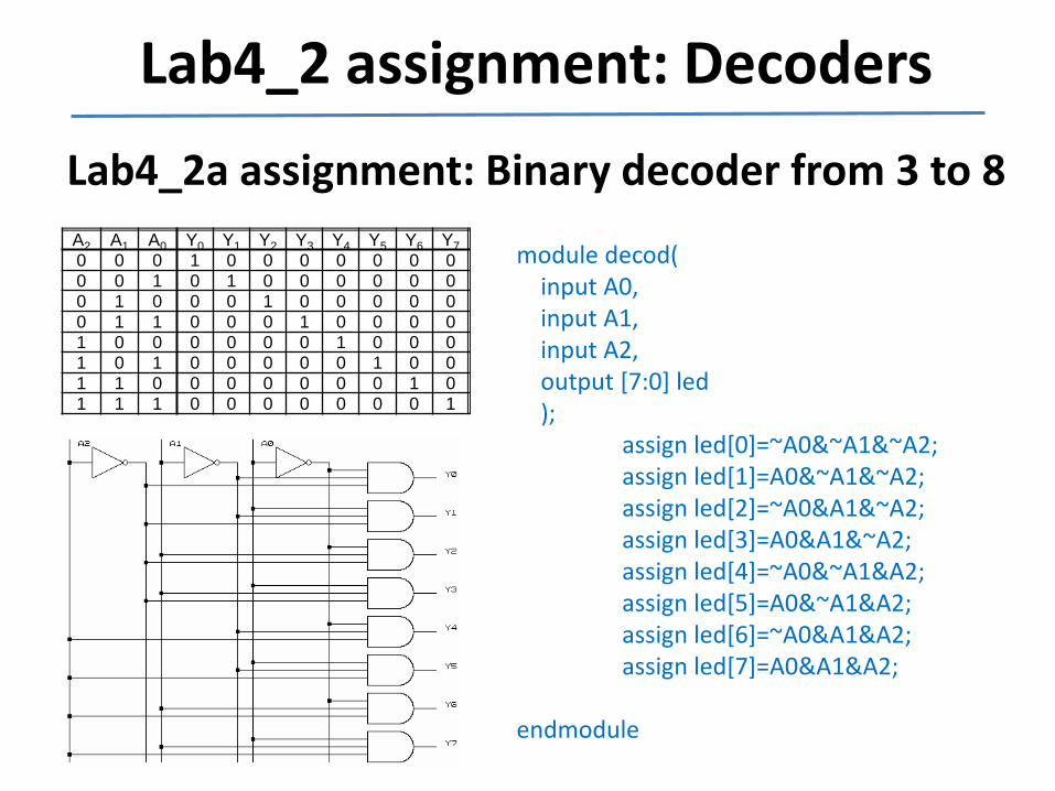
Lab4_2 assignment: DecodersLab4_2a assignment: Binary decoder from 3 to 8A2 A1 A0 Y0 Y1 Y2 Y3 Y4 Y5 Y6 Y70 0 0 1 0 0 0 0 0 0 00 0 1 0 1 0 0 0 0 0 00 1 0 0 0 1 0 0 0 0 00 1 1 0 0 0 1 0 0 0 01 0 0 0 0 0 0 1 0 0 01 0 1 0 0 0 0 0 1 0 01 1 0 0 0 0 0 0 0 1 01 1 1 0 0 0 0 0 0 0 1
module decod(input A0,input A1,input A2,output [7:0] led);
assign led[0]=~A0&~A1&~A2;assign led[1]=A0&~A1&~A2;assign led[2]=~A0&A1&~A2;assign led[3]=A0&A1&~A2;assign led[4]=~A0&~A1&A2;assign led[5]=A0&~A1&A2;assign led[6]=~A0&A1&A2;assign led[7]=A0&A1&A2;
endmodule
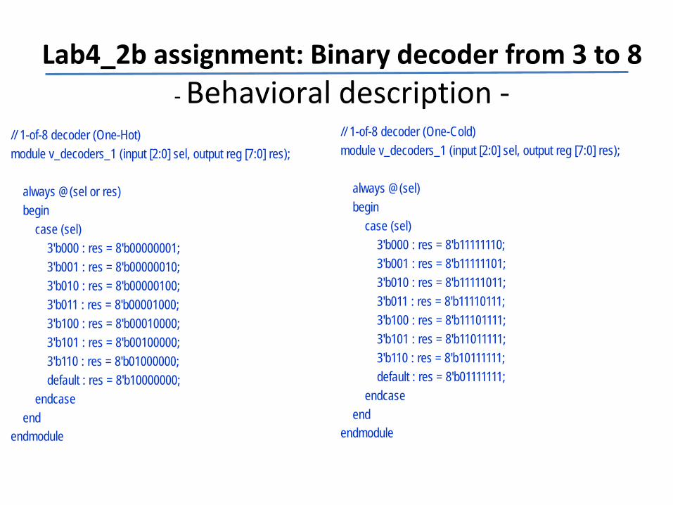
Lab4_2b assignment: Binary decoder from 3 to 8 - Behavioral description -
// 1-of-8 decoder (One-Hot)module v_decoders_1 (input [2:0] sel, output reg [7:0] res);
always @(sel or res)begin
case (sel)3'b000 : res = 8'b00000001;3'b001 : res = 8'b00000010;3'b010 : res = 8'b00000100;3'b011 : res = 8'b00001000;3'b100 : res = 8'b00010000;3'b101 : res = 8'b00100000;3'b110 : res = 8'b01000000;default : res = 8'b10000000;
endcaseend
endmodule
// 1-of-8 decoder (One-Cold)module v_decoders_1 (input [2:0] sel, output reg [7:0] res);
always @(sel)begin
case (sel)3'b000 : res = 8'b11111110;3'b001 : res = 8'b11111101;3'b010 : res = 8'b11111011;3'b011 : res = 8'b11110111;3'b100 : res = 8'b11101111;3'b101 : res = 8'b11011111;3'b110 : res = 8'b10111111;default : res = 8'b01111111;
endcaseend
endmodule
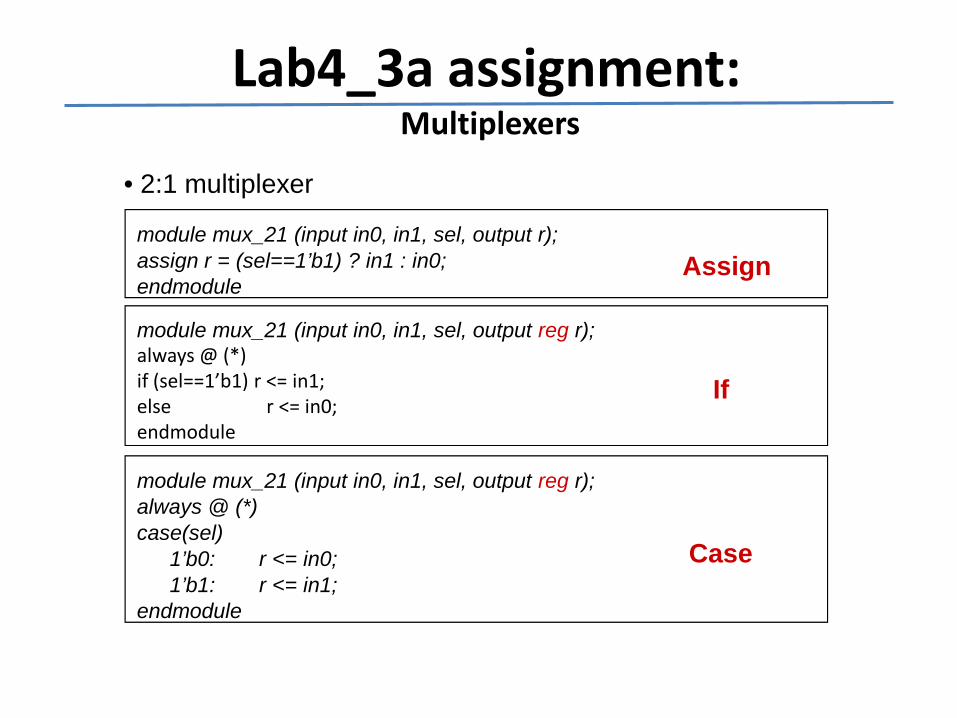
Lab4_3a assignment:Multiplexers
• 2:1 multiplexer
module mux_21 (input in0, in1, sel, output r);assign r = (sel==1’b1) ? in1 : in0;endmodule
module mux_21 (input in0, in1, sel, output reg r);always @ (*)if (sel==1’b1) r <= in1;else r <= in0;endmodule
module mux_21 (input in0, in1, sel, output reg r);always @ (*)case(sel)
1’b0: r <= in0;1’b1: r <= in1;
endmodule
Assign
If
Case
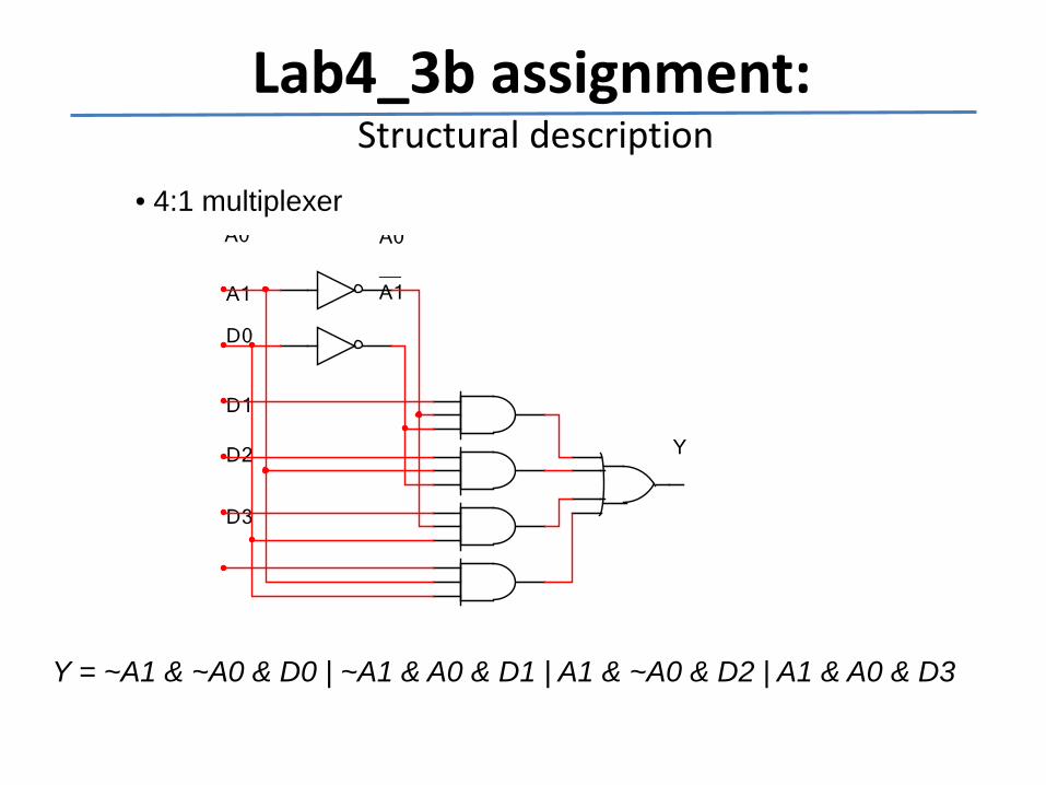
Lab4_3b assignment:Structural description
• 4:1 multiplexerA0 A0
__A1A1
D0
D1
D2
D3
Y
Y = ~A1 & ~A0 & D0 | ~A1 & A0 & D1 | A1 & ~A0 & D2 | A1 & A0 & D3
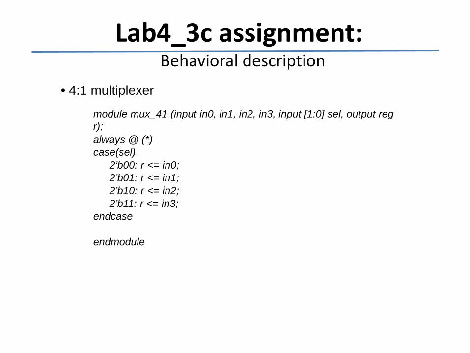
Lab4_3c assignment:Behavioral description
• 4:1 multiplexer
module mux_41 (input in0, in1, in2, in3, input [1:0] sel, output reg r);always @ (*)case(sel)
2’b00: r <= in0;2’b01: r <= in1;2’b10: r <= in2;2’b11: r <= in3;
endcase
endmodule
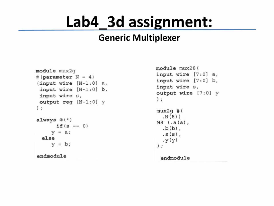
Lab4_3d assignment:Generic Multiplexer