Embed Size (px)
Citation preview
CSM_H5F_DS_E_3_3
1
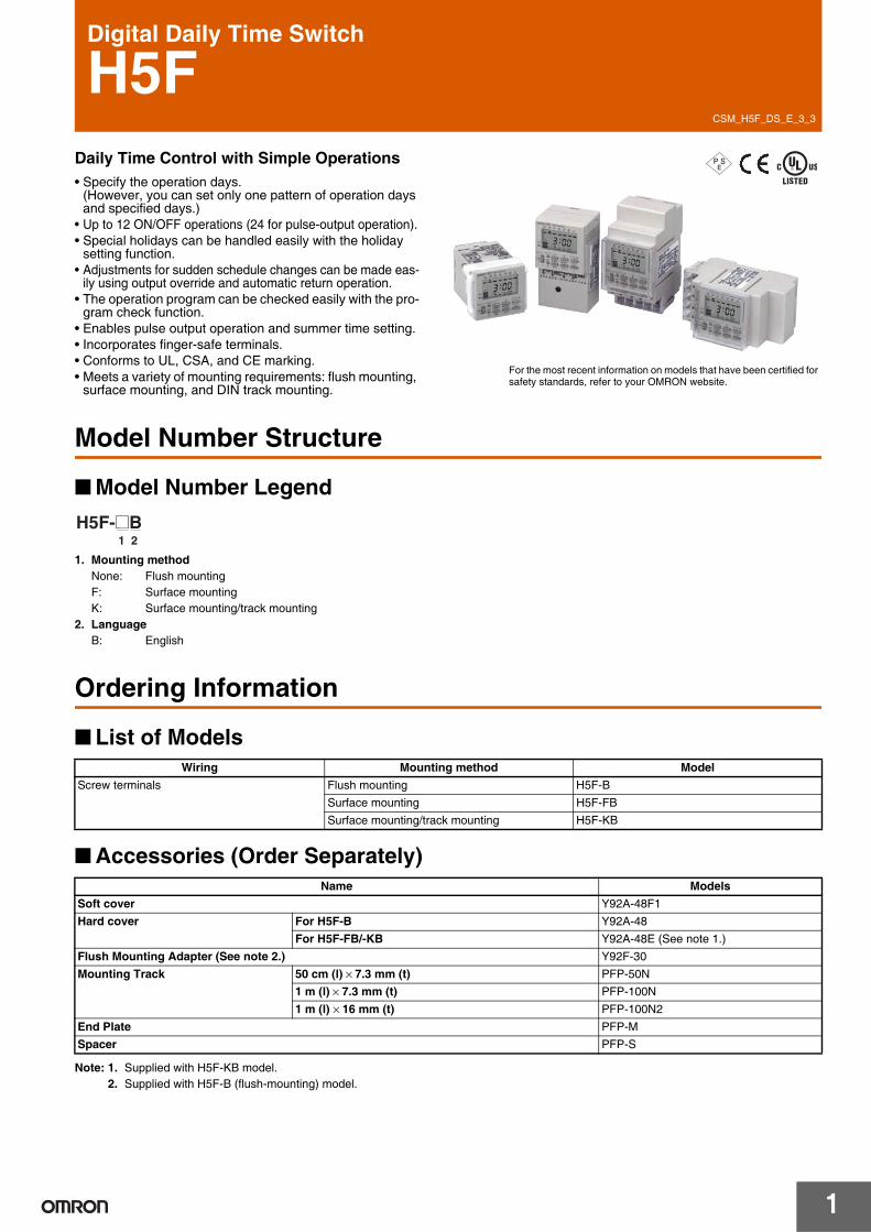
Digital Daily Time Switch
H5FDaily Time Control with Simple Operations• Specify the operation days.
(However, you can set only one pattern of operation days and specified days.)
• Up to 12 ON/OFF operations (24 for pulse-output operation).• Special holidays can be handled easily with the holiday
setting function.• Adjustments for sudden schedule changes can be made eas-
ily using output override and automatic return operation.• The operation program can be checked easily with the pro-
gram check function.• Enables pulse output operation and summer time setting.• Incorporates finger-safe terminals.• Conforms to UL, CSA, and CE marking.• Meets a variety of mounting requirements: flush mounting,
surface mounting, and DIN track mounting.
P S E
For the most recent information on models that have been certified for safety standards, refer to your OMRON website.
Model Number Structure
Model Number Legend
1. Mounting methodNone: Flush mountingF: Surface mountingK: Surface mounting/track mounting
2. LanguageB: English
Ordering Information
List of Models
Accessories (Order Separately)
Note: 1. Supplied with H5F-KB model.2. Supplied with H5F-B (flush-mounting) model.
1 2H5F-@B
Wiring Mounting method ModelScrew terminals Flush mounting H5F-B
Surface mounting H5F-FBSurface mounting/track mounting H5F-KB
Name ModelsSoft cover Y92A-48F1Hard cover For H5F-B Y92A-48
For H5F-FB/-KB Y92A-48E (See note 1.)Flush Mounting Adapter (See note 2.) Y92F-30Mounting Track 50 cm (l) × 7.3 mm (t) PFP-50N
1 m (l) × 7.3 mm (t) PFP-100N1 m (l) × 16 mm (t) PFP-100N2
End Plate PFP-MSpacer PFP-S
H5F
2
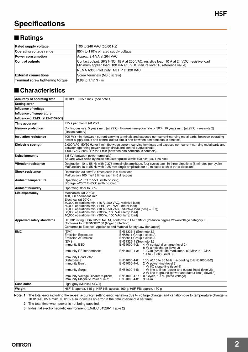
Specifications
Ratings
Characteristics
Note: 1. The total error including the repeat accuracy, setting error, variation due to voltage change, and variation due to temperature change is±0.01%±0.05 s max. ±0.01% also indicates an error in the time interval of a set time.
2. The total time when power is not being supplied.3. Industrial electromagnetic environment (EN/IEC 61326-1 Table 2)
Rated supply voltage 100 to 240 VAC (50/60 Hz)Operating voltage range 85% to 110% of rated supply voltagePower consumption Approx. 2.4 VA at 264 VACControl outputs Contact output: SPST-NO, 15 A at 250 VAC, resistive load, 10 A at 24 VDC, resistive load
Minimum applied load: 100 mA at 5 VDC (failure level: P, reference value)NEMA A300 Pilot Duty, 1/3 HP at 120 VAC
External connections Screw terminals (M3.5 screw)Terminal screw tightening torque 0.98 to 1.17 N · m
Accuracy of operating time ±0.01% ±0.05 s max. (see note 1)Setting errorInfluence of voltageInfluence of temperatureInfluence of EMS. (at EN61326-1)
Time accuracy ±15 s per month (at 25°C)Memory protection Continuous use: 5 years min. (at 25°C); Power-interruption rate of 50%: 10 years min. (at 25°C) (see note 2)
(lithium battery)Insulation resistance 100 MΩ min. (between current-carrying terminals and exposed non-current-carrying metal parts, between operating
power supply circuit and control output circuit and between non-continuous contacts)Dielectric strength 2,000 VAC, 50/60 Hz for 1 min (between current-carrying terminals and exposed non-current-carrying metal parts and
between operating power supply circuit and control output circuit)1,000 VAC, 50/60 Hz for 1 min (between non-continuous contacts)
Noise immunity 1.5 kV (between power terminals)Square-wave noise by noise simulator (pulse width: 100 ns/1 μs, 1-ns rise)
Vibration resistance Destruction:10 to 55 Hz with 0.375-mm single amplitude, four cycles each in three directions (8 minutes per cycle)Malfunction:10 to 55 Hz with 0.25-mm single amplitude for 10 minutes each in three directions
Shock resistance Destruction:300 m/s2 3 times each in 6 directionsMalfunction:100 m/s2 3 times each in 6 directions
Ambient temperature Operating:–10°C to 55°C (with no icing)Storage: –25°C to 65°C (with no icing)
Ambient humidity Operating: 35% to 85%Life expectancy Mechanical (at 20°C):
100,000 operations min.Electrical (at 20°C):50,000 operations min. (15 A, 250 VAC, resistive load)50,000 operations min. (1 HP, 250 VAC, motor load)50,000 operations min. (10 A, 250 VAC, inductive load (cosφ = 0.7))50,000 operations min. (100 W, 100 VAC, lamp load)10,000 operations min. (300 W, 100 VAC, lamp load)
Approved safety standards UL508/Listing, CSA C22.2 No. 14, conforms to EN61010-1 (Pollution degree 2/overvoltage category II)Conforms to VDE0106/P100 (finger protection).Conforms to Electrical Appliance and Material Safety Law (for Japan)
EMC (EMI) EN61326-1 (See note 3.)Emission Enclosure: EN55011 Group 1 class AEmission AC mains: EN55011 Group 1 class A(EMS) EN61326-1 (See note 3.)Immunity ESD: EN61000-4-2: 4 kV contact discharge (level 2)
8 kV air discharge (level 3)Immunity RF-interference: EN61000-4-3: 10 V/m (Amplitude-modulated, 80 MHz to 1 GHz,
1.4 to 2 GHz) (level 3)Immunity ConductedDisturbance: EN61000-4-6: 10 V (0.15 to 80 MHz) (according to EN61000-6-2)Immunity Burst: EN61000-4-4: 2 kV power-line (level 3)
1 kV I/O signal-line (level 4)Immunity Surge: EN61000-4-5: 1 kV line to lines (power and output lines) (level 2);
2 kV line to ground (power and output lines) (level 3)Immunity Voltage Dip/Interruption: EN61000-4-11: 0.5 cycle, 100% (rated voltage)Immunity Magnetic Power Field: EN61000-4-8: 30 A/m
Case color Light gray (Munsell 5Y7/1)Weight H5F-B: approx. 115 g; H5F-KB: approx. 160 g; H5F-FB: approx. 130 g
H5F
3
Connections
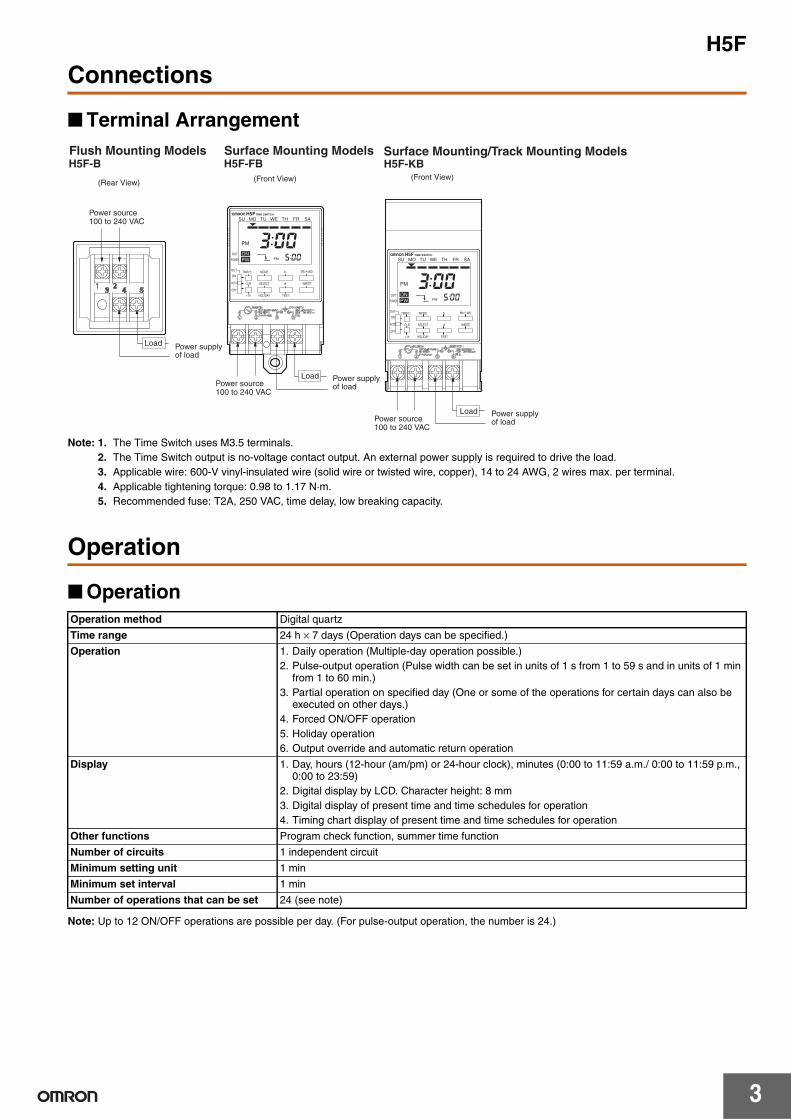
Terminal Arrangement
Note: 1. The Time Switch uses M3.5 terminals.2. The Time Switch output is no-voltage contact output. An external power supply is required to drive the load.3. Applicable wire: 600-V vinyl-insulated wire (solid wire or twisted wire, copper), 14 to 24 AWG, 2 wires max. per terminal.4. Applicable tightening torque: 0.98 to 1.17 N·m.5. Recommended fuse: T2A, 250 VAC, time delay, low breaking capacity.
Operation
Operation
Note: Up to 12 ON/OFF operations are possible per day. (For pulse-output operation, the number is 24.)
H5F-B H5F-FB H5F-KB
PWON
PM
PM
3 00 5 00
H5F TIME SWITCH
SU MO TU WE TH FR SA
PWON
PM
PM
3 00 5 00
H5F TIME SWITCH
SU MO TU WE TH FR SA
Flush Mounting Models
Power source100 to 240 VAC
Power source100 to 240 VAC
Power supplyof load
Load
Power supplyof load
Load
Power source100 to 240 VAC
Power supplyof load
Load
Surface Mounting Models Surface Mounting/Track Mounting Models
(Rear View) (Front View) (Front View)
WRITE
m/ WD
d
h
SELECT
MODE
CLR
OUT
POWER
ON
AUTO
OUT
OFF
TESTHOLIDAY+1h
TMR/ P P
WRITE
m/ WD
d
h
SELECT
MODE
CLR
OUT
POWER
ON
AUTO
OUT
OFF
TESTHOLIDAY+1h
TMR/ P P
Operation method Digital quartz
Time range 24 h × 7 days (Operation days can be specified.)
Operation 1. Daily operation (Multiple-day operation possible.)2. Pulse-output operation (Pulse width can be set in units of 1 s from 1 to 59 s and in units of 1 min
from 1 to 60 min.)3. Partial operation on specified day (One or some of the operations for certain days can also be
executed on other days.)4. Forced ON/OFF operation5. Holiday operation6. Output override and automatic return operation
Display 1. Day, hours (12-hour (am/pm) or 24-hour clock), minutes (0:00 to 11:59 a.m./ 0:00 to 11:59 p.m., 0:00 to 23:59)
2. Digital display by LCD. Character height: 8 mm3. Digital display of present time and time schedules for operation4. Timing chart display of present time and time schedules for operation
Other functions Program check function, summer time function
Number of circuits 1 independent circuit
Minimum setting unit 1 min
Minimum set interval 1 min
Number of operations that can be set 24 (see note)
H5F
4
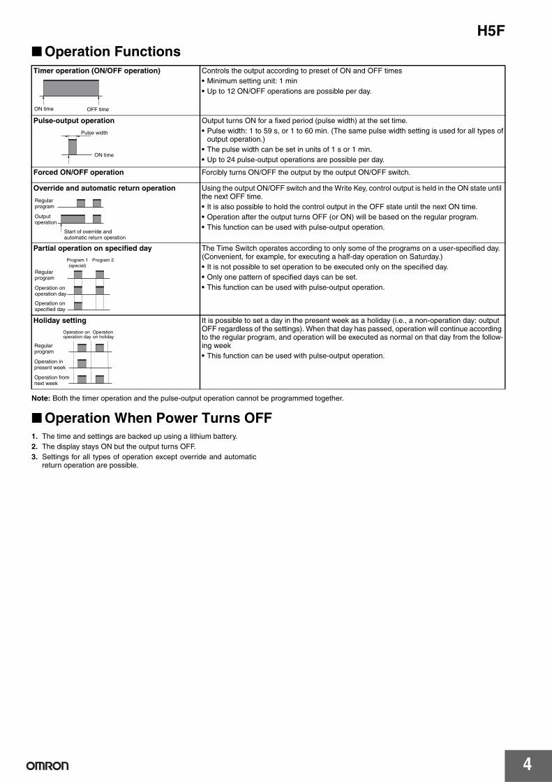
Operation Functions
Note: Both the timer operation and the pulse-output operation cannot be programmed together.
Operation When Power Turns OFF1. The time and settings are backed up using a lithium battery.2. The display stays ON but the output turns OFF.3. Settings for all types of operation except override and automatic
return operation are possible.
Timer operation (ON/OFF operation) Controls the output according to preset of ON and OFF times• Minimum setting unit: 1 min• Up to 12 ON/OFF operations are possible per day.
Pulse-output operation Output turns ON for a fixed period (pulse width) at the set time.• Pulse width: 1 to 59 s, or 1 to 60 min. (The same pulse width setting is used for all types of
output operation.)• The pulse width can be set in units of 1 s or 1 min.• Up to 24 pulse-output operations are possible per day.
Forced ON/OFF operation Forcibly turns ON/OFF the output by the output ON/OFF switch.
Override and automatic return operation Using the output ON/OFF switch and the Write Key, control output is held in the ON state until the next OFF time.• It is also possible to hold the control output in the OFF state until the next ON time.• Operation after the output turns OFF (or ON) will be based on the regular program.• This function can be used with pulse-output operation.
Partial operation on specified day The Time Switch operates according to only some of the programs on a user-specified day. (Convenient, for example, for executing a half-day operation on Saturday.)• It is not possible to set operation to be executed only on the specified day.• Only one pattern of specified days can be set.• This function can be used with pulse-output operation.
Holiday setting It is possible to set a day in the present week as a holiday (i.e., a non-operation day: output OFF regardless of the settings). When that day has passed, operation will continue according to the regular program, and operation will be executed as normal on that day from the follow-ing week• This function can be used with pulse-output operation.
ON time OFF time
ON time
Pulse width
Outputoperation
Regularprogram
Start of override andautomatic return operation
Operation onoperation day
Operation onspecified day
Regularprogram
Program 1(special)
Program 2
Operation fromnext week
Operation inpresent week
Operation onoperation day
Regularprogram
Operationon holiday
H5F
5
Nomenclature
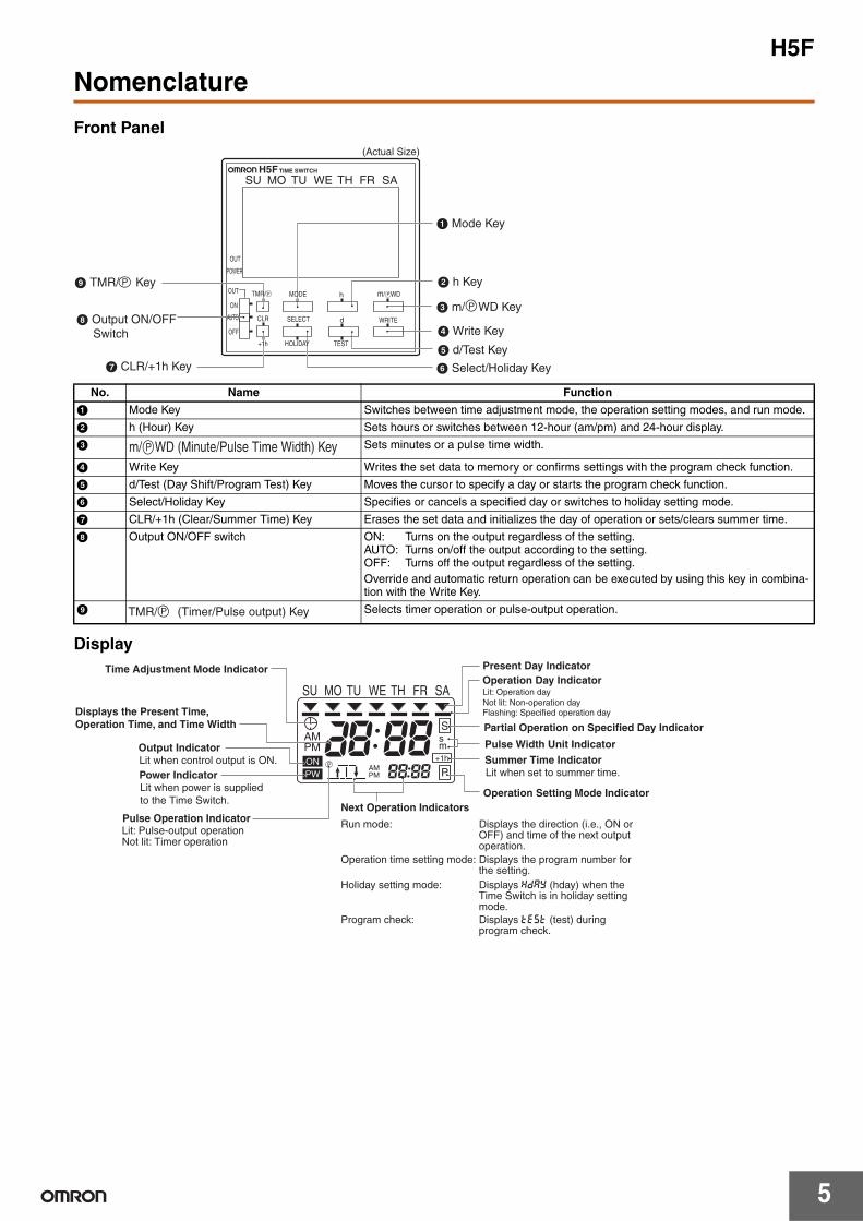
Front Panel
Display
No. Name Function
A Mode Key Switches between time adjustment mode, the operation setting modes, and run mode.
B h (Hour) Key Sets hours or switches between 12-hour (am/pm) and 24-hour display.
C Sets minutes or a pulse time width.
D Write Key Writes the set data to memory or confirms settings with the program check function.
E d/Test (Day Shift/Program Test) Key Moves the cursor to specify a day or starts the program check function.
F Select/Holiday Key Specifies or cancels a specified day or switches to holiday setting mode.
G CLR/+1h (Clear/Summer Time) Key Erases the set data and initializes the day of operation or sets/clears summer time.
H Output ON/OFF switch ON: Turns on the output regardless of the setting.AUTO: Turns on/off the output according to the setting.OFF: Turns off the output regardless of the setting.Override and automatic return operation can be executed by using this key in combina-tion with the Write Key.
I Selects timer operation or pulse-output operation.
A Mode Key
H Output ON/OFF Switch
G CLR/+1h Key
B h Key
C m/ WD Key
D Write Key
E d/Test Key
F Select/Holiday Key
I TMR/ Key P
P
(Actual Size)
H5F TIME SWITCH
SU MO TU WE TH FR SA
WRITE
m/ WD
d
h
SELECT
MODE
CLR
OUT
POWER
ON
AUTO
OUT
OFF
TESTHOLIDAY+1h
TMR/ PP
m/ WD (Minute/Pulse Time Width) KeyP
TMR/ (Timer/Pulse output) KeyP
ON
AMPM
AMPM P
S
+1h
sm
P
PW
SU MO TU WE TH FR SA
Time Adjustment Mode Indicator
Displays the Present Time, Operation Time, and Time Width
Output Indicator
Pulse Operation Indicator
Partial Operation on Specified Day Indicator
Pulse Width Unit Indicator
Operation Setting Mode IndicatorNext Operation Indicators
Lit when control output is ON.
Lit: Pulse-output operationNot lit: Timer operation
Lit: Operation dayNot lit: Non-operation dayFlashing: Specified operation day
Power IndicatorLit when power is suppliedto the Time Switch.
Run mode: Displays the direction (i.e., ON or OFF) and time of the next output operation.
Operation time setting mode: Displays the program number for the setting.
Holiday setting mode: Displays hday (hday) when the Time Switch is in holiday setting mode.
Program check: Displays test (test) during program check.
Summer Time IndicatorLit when set to summer time.
Present Day IndicatorOperation Day Indicator
H5F
6
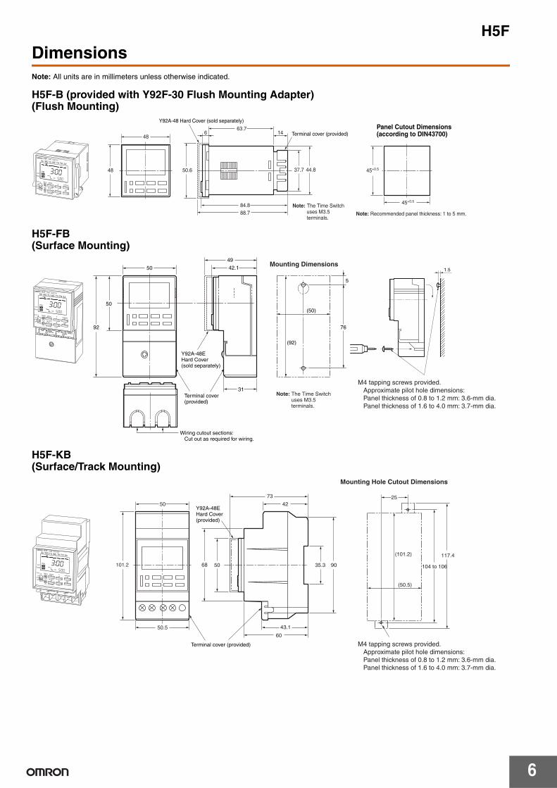
DimensionsNote: All units are in millimeters unless otherwise indicated.
H5F-B (provided with Y92F-30 Flush Mounting Adapter)(Flush Mounting)
H5F-FB(Surface Mounting)
H5F-KB(Surface/Track Mounting)
63.714
37.7 44.8
84.888.7
50.6 45
6
+0.5
45+0.5
SET
TEST
m/ WD
dSELECT
HOLIDAY
CLR
ON
OUT
OUT
POWER
AUTOOFF
+1h
hMODE
TMR/
H5F TIME SWITCH
5 00
3 00PWONPM
PM
SU MO TU WE TH FR SA
P
P
48
48
Terminal cover (provided)
Y92A-48 Hard Cover (sold separately)
Note: The Time Switch uses M3.5 terminals.
Note: Recommended panel thickness: 1 to 5 mm.
Panel Cutout Dimensions(according to DIN43700)
42.1
31
49
(50)
(92)
5
76
1.5
15A10ARES.4
32
1 250VAC24VDC
100 to 240VAC50/60Hz2.4VA max.
H5F TIME SWITCH
5 00
3 00PWONPM
PM
50
50
92
Mounting Dimensions
Wiring cutout sections: Cut out as required for wiring.
Y92A-48EHard Cover(sold separately)
Terminal cover(provided)
Note: The Time Switch uses M3.5 terminals.
M4 tapping screws provided. Approximate pilot hole dimensions: Panel thickness of 0.8 to 1.2 mm: 3.6-mm dia. Panel thickness of 1.6 to 4.0 mm: 3.7-mm dia.
SET
TEST
m/ WD
dSELECT
HOLIDAY
CLR
ON
OUT
OUT
POWER
AUTOOFF
+1h
hMODETMR/ P
P
SU MO TU WE TH FR SA
42
73 25
60
43.1
5068
(50.5)
(101.2)
9035.3
117.4H5F TIME SWITCH
5 00
3 00PWONPM
PM
RES.43
21 2.4VA max.
50
101.2
50.5
Mounting Hole Cutout Dimensions
104 to 106
M4 tapping screws provided. Approximate pilot hole dimensions: Panel thickness of 0.8 to 1.2 mm: 3.6-mm dia. Panel thickness of 1.6 to 4.0 mm: 3.7-mm dia.
Terminal cover (provided)
Y92A-48EHard Cover(provided)
SET
TEST
m/ WD
dSELECT
HOLIDAY
CLR
ON
OUT
OUT
POWER
AUTOOFF
+1h
hMODETMR/ P
P
SU MO TU WE TH FR SA
H5F
7
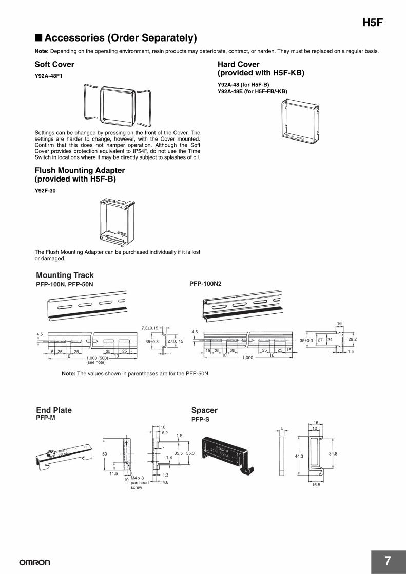
Accessories (Order Separately)Note: Depending on the operating environment, resin products may deteriorate, contract, or harden. They must be replaced on a regular basis.
Soft CoverY92A-48F1
Settings can be changed by pressing on the front of the Cover. Thesettings are harder to change, however, with the Cover mounted.Confirm that this does not hamper operation. Although the SoftCover provides protection equivalent to IP54F, do not use the TimeSwitch in locations where it may be directly subject to splashes of oil.
Flush Mounting Adapter (provided with H5F-B)Y92F-30
The Flush Mounting Adapter can be purchased individually if it is lostor damaged.
Hard Cover(provided with H5F-KB)Y92A-48 (for H5F-B)Y92A-48E (for H5F-FB/-KB)
4.5
15 25 25 25 25 *10 10
7.3±0.15
35±0.3 27±0.15
1
4.5
15 25 25 25 25 1510 101,000
27 24
16
29.2
1 1.5
50
11.5
106.2
1.8
135.5 35.3
1.8
1.3
4.8
516
12
44.3
16.510
34.8
35±0.3
Mounting Track PFP-100N, PFP-50N PFP-100N2
End PlatePFP-M
SpacerPFP-S
Note: The values shown in parentheses are for the PFP-50N.
1,000 (500) (see note)
M4 x 8 pan head screw
H5F
8
PrecautionsRefer to Safety Precautions for All Timers.
!CAUTIONDo not touch any of the terminals while power is being supplied. Doing so may result in electric shock. Be sure to mount the terminal cover after wiring.
Do not use the Time Switch in locations subject to flammable or explosive gases. Doing so may result in explosion.
Do not disassemble, repair, or modify the Time Switch. Doing so may result in electric shock, fire, or malfunction.
Tighten terminal screws to the specified torque (approx. 0.98 N⋅m). Loose screws may occasionally cause fires or malfunction. (Maximum torque: 1.17 N⋅m)
Before changing times or other settings while power is being supplied, either turn OFF the power on the load side or set the output ON/OFF switch to OFF and confirm the safety of the system.
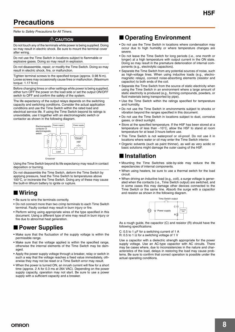
The life expectancy of the output relays depends on the switching capacity and switching conditions. Consider the actual application conditions and use the Time Switch within the rated load and electrical service life. If using the Time Switch beyond its ratings is unavoidable, use it together with an electromagnetic switch or contactor as shown in the following diagram.
Using the Time Switch beyond its life expectancy may result in contact deposition or burning.
Do not disassemble the Time Switch, deform the Time Switch by applying pressure, heat the Time Switch to temperatures above 100°C, or incinerate the Time Switch. Doing any of these may cause the built-in lithium battery to ignite or rupture.
Wiring• Be sure to wire the terminals correctly.• Do not connect more than two crimp terminals to each Time Switch
terminal. Faulty contact may result in burn injury or fire.• Perform wiring using appropriate wires of the type specified in this
document. Using a different type of wire may result in burn injury orfire due to abnormal heat generation.
Power Supplies• Make sure that the fluctuation of the supply voltage is within the
permissible range.• Make sure that the voltage applied is within the specified range,
otherwise the internal elements of the Time Switch may be dam-aged.
• Apply the power supply voltage through a breaker, relay or switch insuch a way that the voltage reaches a fixed value immediately, oth-erwise they may not be reset or a Time Switch error may result.
• When the power is turned ON, an inrush current will flow for a shorttime (approx. 2 A for 0.3 ms at 264 VAC). Depending on the powersupply capacity, operation may not start. Be sure to use a powersupply with a sufficient capacity and a breaker.
Operating Environment• Do not use the Time Switch in locations where condensation may
occur due to high humidity or where temperature changes aresevere.
• Do not leave the Time Switch for long periods (i.e., one month orlonger) at a high temperature with output current in the ON state.Doing so may result in the premature deterioration of internal com-ponents (e.g., electrolytic capacitors).
• Separate the Time Switch from any potential sources of noise, suchas high-voltage lines. When using inductive loads (e.g., electro-magnetic relays), connect noise-absorbing elements (resistor andcapacitor) to both ends of the coil.
• Separate the Time Switch from the source of static electricity whenusing the Time Switch in an environment where a large amount ofstatic electricity is produced (e.g., forming compounds, powders, orfluid materials being transported by pipe).
• Use the Time Switch within the ratings specified for temperatureand humidity.
• Do not use the Time Switch in environments subject to shocks orvibration beyond the ranges specified in this document.
• Do not use the Time Switch in locations subject to dust, corrosivegases, or direct sunlight.
• Store at the specified temperature. If the H5F has been stored at atemperature of less than −10°C, allow the H5F to stand at roomtemperature for at least 3 hours before use.
• This Time Switch is not waterproof or oil-proof. Do not use it inlocations where water or oil may enter the Time Switch interior.
• Organic solvents (such as paint thinner), as well as very acidic orbasic solutions might damage the outer casing of the H5F.
Installation• Mounting the Time Switches side-by-side may reduce the life
expectancies of internal components.• When using heaters, be sure to use a thermal switch for the load
circuit.• When driving an inductive load (e.g., coil), a surge voltage is gener-
ated when the contacts (i.e., Time Switch output) are switched, andin some cases this may damage other devices connected to theTime Switch or the same line. Absorb the surge with a capacitorand resistor as shown in the following diagram.
As a rough guide, the capacitor (C) and resistor (R) should have thefollowing specifications:
C: 0.5 to 1 µF for a switching current of 1 AR: 0.5 to 1 Ω for a switching voltage of 1 V
Use a capacitor with a dielectric strength appropriate for the powersupply voltage. Use an AC-type capacitor with AC circuits. Theremay be cases where, due to inconsistencies in the nature and char-acteristics of the load, delays in restoring the load may cause prob-lems. Be sure to confirm that correct operation is possible under theactual operating conditions.
Power supplyElectromagneticcontactor orelectromagneticswitch
Circuit
Load
H5F
Crossover
Power supply
C
R
Time Switch output
Power supply Inductiveload

H5F
9
Precautions for EN61010-1 Conformance
The H5F Time Switch conforms to EN61010-1 provided that the fol-lowing conditions are satisfied:
Basic insulation is provided between the power supply and outputterminals of the H5F.
• Output terminals are connected to devices without exposedcharged parts.
• Output terminals are connected to devices with basic insulation thatis suitable for the maximum operating voltage.
OthersNone of the Time Switch components are user-replaceable, includingthe battery.
H5F
10
Operating Method
Operating Method
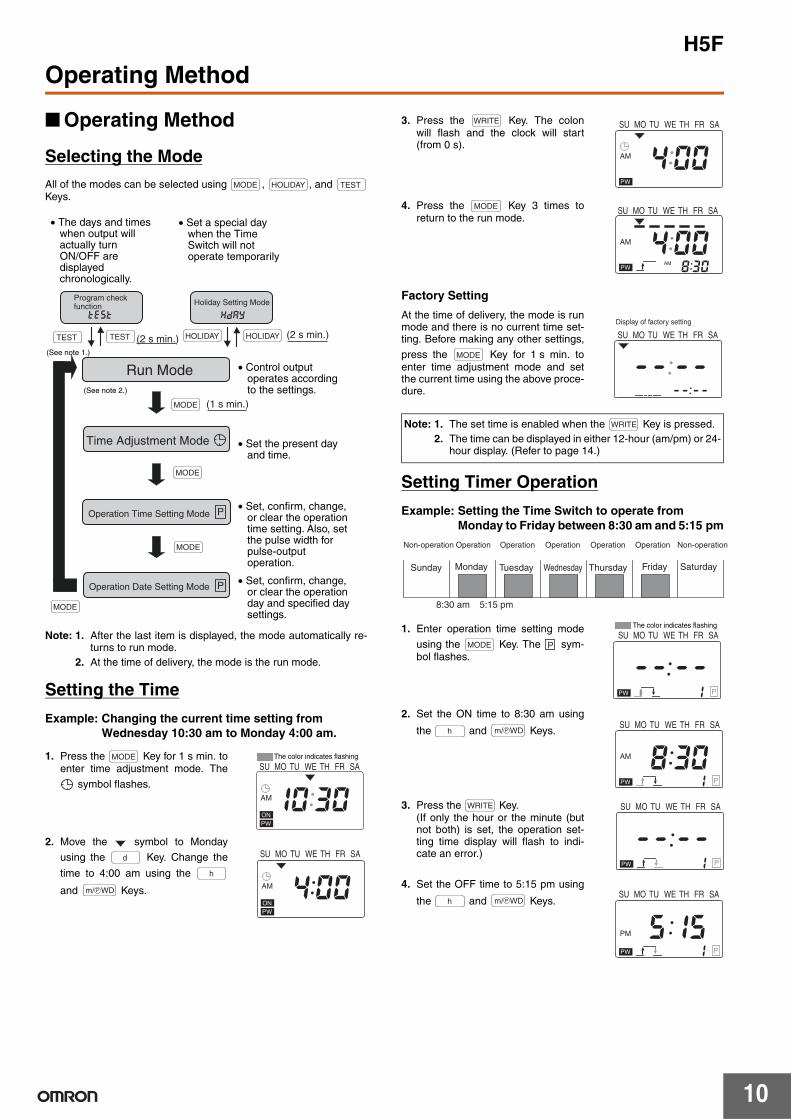
Selecting the Mode
All of the modes can be selected using , , and Keys.
Note: 1. After the last item is displayed, the mode automatically re-turns to run mode.
2. At the time of delivery, the mode is the run mode.
Setting the Time
Example: Changing the current time setting from Wednesday 10:30 am to Monday 4:00 am.
1. Press the Key for 1 s min. toenter time adjustment mode. The
symbol flashes.
2. Move the symbol to Monday
using the Key. Change the
time to 4:00 am using the
and Keys.
3. Press the Key. The colonwill flash and the clock will start(from 0 s).
4. Press the Key 3 times toreturn to the run mode.
Factory Setting
At the time of delivery, the mode is runmode and there is no current time set-ting. Before making any other settings,
press the Key for 1 s min. toenter time adjustment mode and setthe current time using the above proce-dure.
Setting Timer Operation
Example: Setting the Time Switch to operate from Monday to Friday between 8:30 am and 5:15 pm
1. Enter operation time setting mode
using the Key. The sym-bol flashes.
2. Set the ON time to 8:30 am using
the and Keys.
3. Press the Key.(If only the hour or the minute (butnot both) is set, the operation set-ting time display will flash to indi-cate an error.)
4. Set the OFF time to 5:15 pm using
the and Keys.
MODE HOLIDAY TEST
P
P
Operation Date Setting Mode
Operation Time Setting Mode
Time Adjustment Mode
Run Mode
test
Holiday Setting Mode
hday
(2 s min.)
• The days and times when output will actually turn ON/OFF are displayed chronologically.
• Set a special day when the Time Switch will not operate temporarily
(See note 1.)
(2 s min.)
(See note 2.)
(1 s min.)
• Control output operates according to the settings.
• Set the present day and time.
• Set, confirm, change, or clear the operation time setting. Also, set the pulse width for pulse-output operation.
• Set, confirm, change, or clear the operation day and specified day settings.
Program check function
TEST TEST HOLIDAY HOLIDAY
MODE
MODE
MODE
MODE
MODE
10 30ON
AM
PW
SU MO TU WE TH FR SAThe color indicates flashing
d
h
Pm/ WD 4 00ON
AM
PW
SU MO TU WE TH FR SA
Note: 1. The set time is enabled when the Key is pressed.2. The time can be displayed in either 12-hour (am/pm) or 24-
hour display. (Refer to page 14.)
WRITE
4 00AM
PW
SU MO TU WE TH FR SA
MODE
8 30
4 00AM
AMPW
SU MO TU WE TH FR SA
MODE
-- --
-- --
SU MO TU WE TH FR SA
Display of factory setting
WRITE
Non-operation Operation
Sunday Monday Tuesday Wednesday Thursday Friday Saturday
8:30 am 5:15 pm
Operation Operation Operation Operation Non-operation
MODE P
-- --PPW 1
SU MO TU WE TH FR SAThe color indicates flashing
h Pm/ WD
8 30AM
PPW 1
SU MO TU WE TH FR SA
WRITE
-- --PPW 1
SU MO TU WE TH FR SA
h Pm/ WD
5 15PM
PPW 1
SU MO TU WE TH FR SA
H5F
11
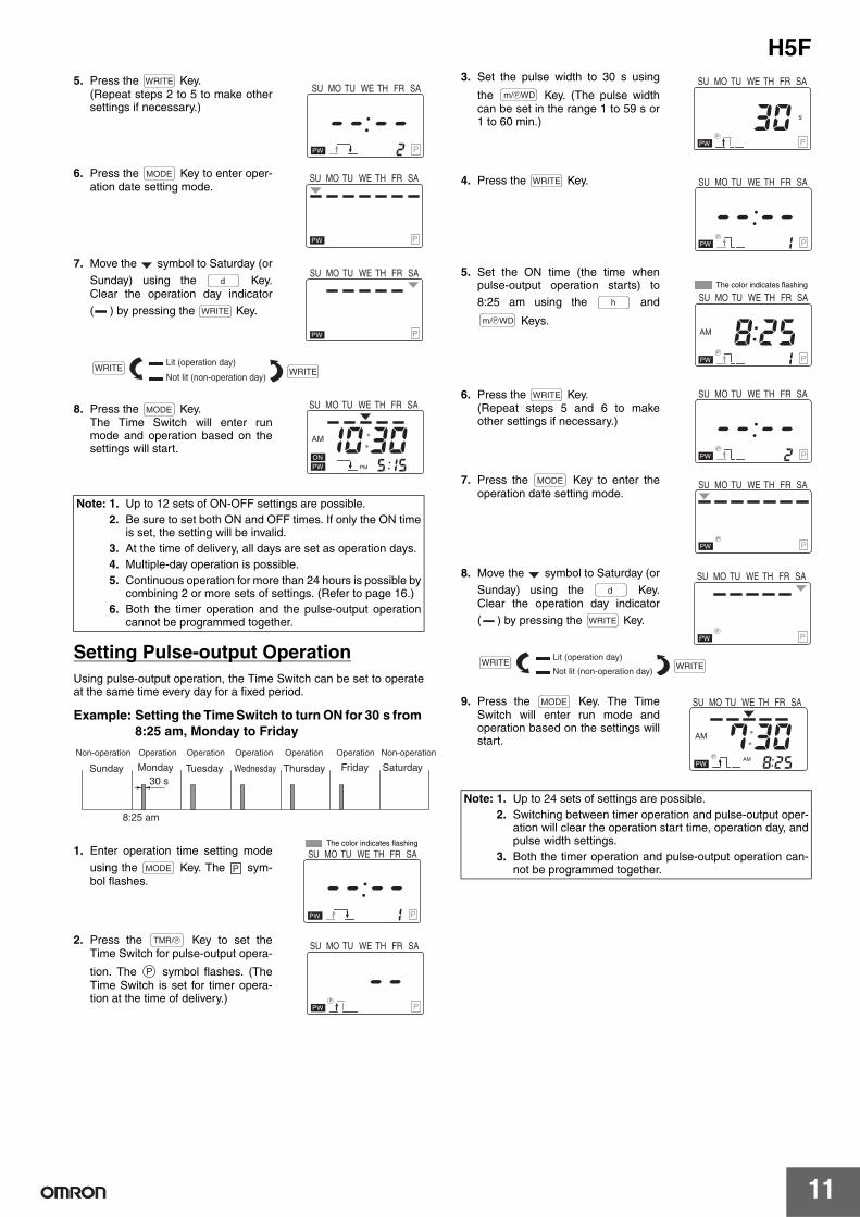
5. Press the Key.(Repeat steps 2 to 5 to make othersettings if necessary.)
6. Press the Key to enter oper-ation date setting mode.
7. Move the symbol to Saturday (or
Sunday) using the Key.Clear the operation day indicator
( ) by pressing the Key.
8. Press the Key.The Time Switch will enter runmode and operation based on thesettings will start.
Setting Pulse-output OperationUsing pulse-output operation, the Time Switch can be set to operateat the same time every day for a fixed period.
Example: Setting the Time Switch to turn ON for 30 s from 8:25 am, Monday to Friday
1. Enter operation time setting mode
using the Key. The sym-bol flashes.
2. Press the Key to set theTime Switch for pulse-output opera-
tion. The symbol flashes. (TheTime Switch is set for timer opera-tion at the time of delivery.)
3. Set the pulse width to 30 s using
the Key. (The pulse widthcan be set in the range 1 to 59 s or1 to 60 min.)
4. Press the Key.
5. Set the ON time (the time whenpulse-output operation starts) to
8:25 am using the and
Keys.
6. Press the Key.(Repeat steps 5 and 6 to makeother settings if necessary.)
7. Press the Key to enter theoperation date setting mode.
8. Move the symbol to Saturday (or
Sunday) using the Key.Clear the operation day indicator
( ) by pressing the Key.
9. Press the Key. The TimeSwitch will enter run mode andoperation based on the settings willstart.
Note: 1. Up to 12 sets of ON-OFF settings are possible. 2. Be sure to set both ON and OFF times. If only the ON time
is set, the setting will be invalid.3. At the time of delivery, all days are set as operation days.4. Multiple-day operation is possible.5. Continuous operation for more than 24 hours is possible by
combining 2 or more sets of settings. (Refer to page 16.)6. Both the timer operation and the pulse-output operation
cannot be programmed together.
WRITE
-- --PPW 2
SU MO TU WE TH FR SA
MODE
PPW
SU MO TU WE TH FR SA
d
WRITE
PPW
SU MO TU WE TH FR SA
Lit (operation day)
Not lit (non-operation day)WRITEWRITE
MODE
5 15
10 30ON
AM
PMPW
SU MO TU WE TH FR SA
30 sSunday Monday Tuesday Wednesday Thursday Friday Saturday
8:25 am
Non-operation Operation Operation Operation Operation Operation Non-operation
MODE P
1
-- --PPW
SU MO TU WE TH FR SAThe color indicates flashing
PTMR/
P
--P
P
PW
SU MO TU WE TH FR SA
Note: 1. Up to 24 sets of settings are possible.2. Switching between timer operation and pulse-output oper-
ation will clear the operation start time, operation day, andpulse width settings.
3. Both the timer operation and pulse-output operation can-not be programmed together.
Pm/ WD
30P
s
P
PW
SU MO TU WE TH FR SA
WRITE
1
-- --P
P
PW
SU MO TU WE TH FR SA
h
Pm/ WD
1
8 25AM
PP
PW
SU MO TU WE TH FR SAThe color indicates flashing
WRITE
2
-- --P
P
PW
SU MO TU WE TH FR SA
MODE
PP
PW
SU MO TU WE TH FR SA
d
WRITE
PP
PW
SU MO TU WE TH FR SA
Lit (operation day)
Not lit (non-operation day)WRITEWRITE
MODE
8 25
7 30AM
AMP
PW
SU MO TU WE TH FR SA
H5F
12
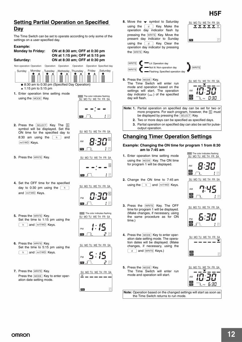
Setting Partial Operation on Specified DayThe Time Switch can be set to operate according to only some of thesettings on a user-specified day.
Example:Monday to Friday: ON at 8:30 am; OFF at 0:30 pm
ON at 1:15 pm; OFF at 5:15 pmSaturday: ON at 8:30 am; OFF at 0:30 pm
1. Enter operation time setting mode
using the Key.
2. Press the Key. The symbol will be displayed. Set theON time for the specified day to
8:30 am using the and
Keys.
3. Press the Key.
4. Set the OFF time for the specified
day to 0:30 pm using the
and Keys.
5. Press the Key.Set the time to 1:15 pm using the
and Keys.
6. Press the Key.Set the time to 5:15 pm using the
and Keys.
7. Press the Key.
Press the Key to enter oper-ation date setting mode.
8. Move the symbol to Saturday
using the Key. Make theoperation day indicator flash by
pressing the Key. Move thepresent day indicator to Sunday
using the Key. Clear theoperation day indicator by pressing
the Key.
9. Press the Key. The Time Switch will enter runmode and operation based on thesettings will start. The operationday indicator ( ) of the specifiedday will flash.
Changing Timer Operation Settings
Example: Changing the ON time for program 1 from 8:30 am to 7:45 am
1. Enter operation time setting mode
using the Key. The ON timefor program 1 will be displayed.
2. Change the ON time to 7:45 am
using the and Keys.
3. Press the Key. The OFFtime for program 1 will be displayed.(Make changes, if necessary, usingthe same procedure as for ONtime.)
4. Press the Key to enter oper-ation date setting mode. The opera-tion dates will be displayed. (Makechanges, if necessary, using the
and Keys.)
5. Press the Key.The Time Switch will enter runmode and operation will start.
Non-operation Operation
8:30 am to 0:30 pm (Specified Day Operation)1:15 pm to 5:15 pm
Sunday Monday Tuesday Wednesday Thursday Friday Saturday
Operation Operation Operation Operation Specified day
MODE
1
-- --PPW
SU MO TU WE TH FR SAThe color indicates flashing
SELECT S
h
Pm/ WD
1
8 30AM
P
S
PW
SU MO TU WE TH FR SA
WRITE
1
-- --P
S
PW
SU MO TU WE TH FR SA
h
Pm/ WD
1
0 30PM
P
S
PW
SU MO TU WE TH FR SA
WRITE
h Pm/ WD
2
1 15PM
PPW
SU MO TU WE TH FR SAThe color indicates flashing
WRITE
h Pm/ WD
2
5 15PM
PPW
SU MO TU WE TH FR SA
WRITE
MODE
PPW
SU MO TU WE TH FR SA
Note: 1. Partial operation on specified day can be set for two ormore programs. For each program, however, the mustbe displayed by pressing the Key.
2. Two or more days can be specified as specified days.3. Partial operation on specified day can also be set for pulse-
output operation.
Note: Operation based on the changed settings will start as soon asthe Time Switch returns to run mode.
d
WRITE
d
WRITE
Lit: Operation day
Not lit: Non-operation day
Flashing: Specified operation day
WRITE
WRITEWRITE
PPW
SU MO TU WE TH FR SA
MODE
0 30
10 30ON
AM
PMPW
SU MO TU WE TH FR SA
SSELECT
MODE
1
8 30ON
AM
PPW
SU MO TU WE TH FR SAThe color indicates flashing
h Pm/ WD
1
7 45ON
AM
PPW
SU MO TU WE TH FR SA
WRITE
1
6 30ON
PM
PPW
SU MO TU WE TH FR SA
MODE
d WRITE ONPPW
SU MO TU WE TH FR SA
MODE
6 30
10 30ON
AM
PMPW
SU MO TU WE TH FR SA
H5F
13
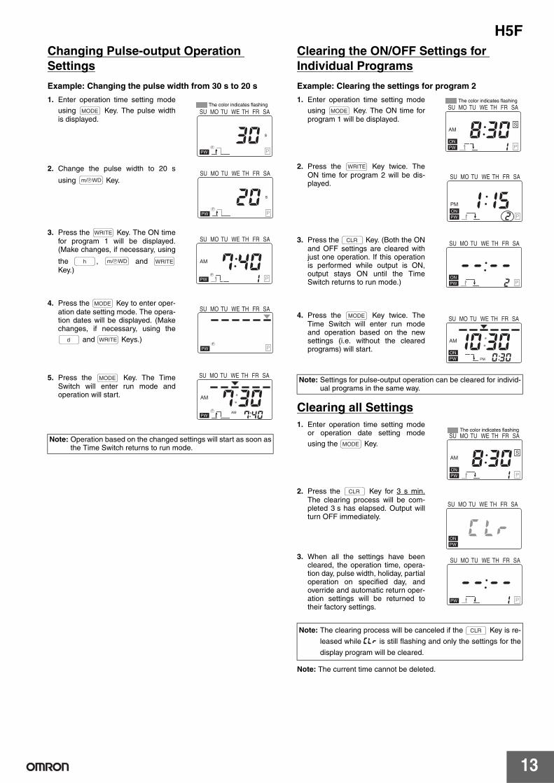
Changing Pulse-output Operation Settings
Example: Changing the pulse width from 30 s to 20 s
1. Enter operation time setting mode
using Key. The pulse widthis displayed.
2. Change the pulse width to 20 s
using Key.
3. Press the Key. The ON timefor program 1 will be displayed.(Make changes, if necessary, using
the , and Key.)
4. Press the Key to enter oper-ation date setting mode. The opera-tion dates will be displayed. (Makechanges, if necessary, using the
and Keys.)
5. Press the Key. The TimeSwitch will enter run mode andoperation will start.
Clearing the ON/OFF Settings for Individual Programs
Example: Clearing the settings for program 2
1. Enter operation time setting mode
using Key. The ON time forprogram 1 will be displayed.
2. Press the Key twice. TheON time for program 2 will be dis-played.
3. Press the Key. (Both the ONand OFF settings are cleared withjust one operation. If this operationis performed while output is ON,output stays ON until the TimeSwitch returns to run mode.)
4. Press the Key twice. TheTime Switch will enter run modeand operation based on the newsettings (i.e. without the clearedprograms) will start.
Clearing all Settings1. Enter operation time setting mode
or operation date setting mode
using the Key.
2. Press the Key for 3 s min.The clearing process will be com-pleted 3 s has elapsed. Output willturn OFF immediately.
3. When all the settings have beencleared, the operation time, opera-tion day, pulse width, holiday, partialoperation on specified day, andoverride and automatic return oper-ation settings will be returned totheir factory settings.
Note: The current time cannot be deleted.
Note: Operation based on the changed settings will start as soon asthe Time Switch returns to run mode.
MODE
30P
s
P
PW
SU MO TU WE TH FR SAThe color indicates flashing
Pm/ WD
20P
s
P
PW
SU MO TU WE TH FR SA
WRITE
h Pm/ WD WRITE
1
7 40AM
PP
PW
SU MO TU WE TH FR SA
MODE
d WRITEP
P
PW
SU MO TU WE TH FR SA
MODE
7 40
7 30AM
AMP
PW
SU MO TU WE TH FR SANote: Settings for pulse-output operation can be cleared for individ-
ual programs in the same way.
Note: The clearing process will be canceled if the Key is re-
leased while clr is still flashing and only the settings for the
display program will be cleared.
MODE
1
8 30ON
AM
P
S
PW
SU MO TU WE TH FR SAThe color indicates flashing
WRITE
2
1 15ON
PM
PPW
SU MO TU WE TH FR SA
CLR
2
-- --P
ONPW
SU MO TU WE TH FR SA
MODE
0 30
10 30ON
AM
PMPW
SU MO TU WE TH FR SA
MODE
1
8 30ON
AM
P
S
PW
SU MO TU WE TH FR SAThe color indicates flashing
CLR
c lrONPW
SU MO TU WE TH FR SA
1
-- --PPW
SU MO TU WE TH FR SA
CLR
H5F
14
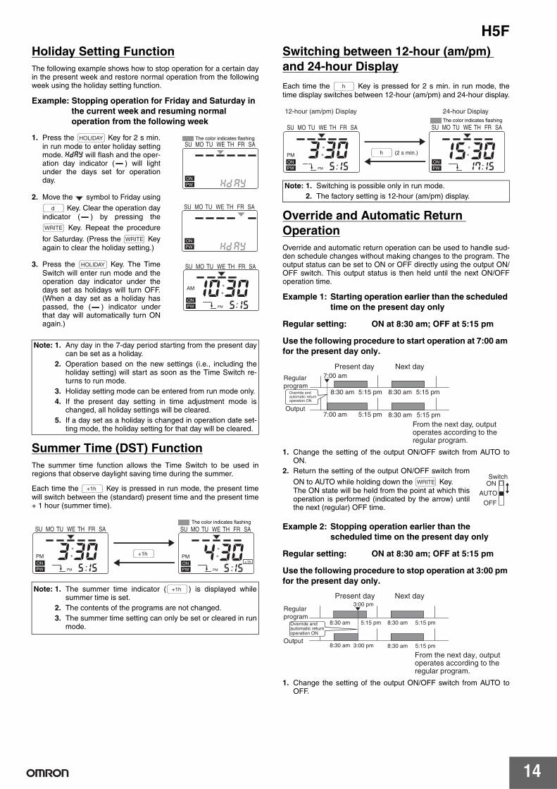
Holiday Setting FunctionThe following example shows how to stop operation for a certain dayin the present week and restore normal operation from the followingweek using the holiday setting function.
Example: Stopping operation for Friday and Saturday in the current week and resuming normal operation from the following week
1. Press the Key for 2 s min.in run mode to enter holiday settingmode. hday will flash and the oper-ation day indicator ( ) will lightunder the days set for operationday.
2. Move the symbol to Friday using
Key. Clear the operation dayindicator ( ) by pressing the
Key. Repeat the procedure
for Saturday. (Press the Keyagain to clear the holiday setting.)
3. Press the Key. The TimeSwitch will enter run mode and theoperation day indicator under thedays set as holidays will turn OFF.(When a day set as a holiday haspassed, the ( ) indicator underthat day will automatically turn ONagain.)
Summer Time (DST) FunctionThe summer time function allows the Time Switch to be used inregions that observe daylight saving time during the summer.
Each time the Key is pressed in run mode, the present timewill switch between the (standard) present time and the present time+ 1 hour (summer time).
Switching between 12-hour (am/pm) and 24-hour Display
Each time the Key is pressed for 2 s min. in run mode, thetime display switches between 12-hour (am/pm) and 24-hour display.
Override and Automatic Return OperationOverride and automatic return operation can be used to handle sud-den schedule changes without making changes to the program. Theoutput status can be set to ON or OFF directly using the output ON/OFF switch. This output status is then held until the next ON/OFFoperation time.
Example 1: Starting operation earlier than the scheduled time on the present day only
Regular setting: ON at 8:30 am; OFF at 5:15 pm
Use the following procedure to start operation at 7:00 am for the present day only.
1. Change the setting of the output ON/OFF switch from AUTO toON.
2. Return the setting of the output ON/OFF switch from
ON to AUTO while holding down the Key.The ON state will be held from the point at which thisoperation is performed (indicated by the arrow) untilthe next (regular) OFF time.
Example 2: Stopping operation earlier than the scheduled time on the present day only
Regular setting: ON at 8:30 am; OFF at 5:15 pm
Use the following procedure to stop operation at 3:00 pm for the present day only.
1. Change the setting of the output ON/OFF switch from AUTO toOFF.
Note: 1. Any day in the 7-day period starting from the present daycan be set as a holiday.
2. Operation based on the new settings (i.e., including theholiday setting) will start as soon as the Time Switch re-turns to run mode.
3. Holiday setting mode can be entered from run mode only.4. If the present day setting in time adjustment mode is
changed, all holiday settings will be cleared.5. If a day set as a holiday is changed in operation date set-
ting mode, the holiday setting for that day will be cleared.
Note: 1. The summer time indicator ( ) is displayed whilesummer time is set.
2. The contents of the programs are not changed.3. The summer time setting can only be set or cleared in run
mode.
HOLIDAY
hd ayONPW
SU MO TU WE TH FR SAThe color indicates flashing
d
WRITE
WRITE
hd ayONPW
SU MO TU WE TH FR SA
HOLIDAY
5 15
10 30ON
AM
PMPW
SU MO TU WE TH FR SA
+1h
5 15
3 30ON
PM
PMPW 5 15
4 30ON
PM
PM
+1h
PW
SU MO TU WE TH FR SA SU MO TU WE TH FR SAThe color indicates flashing
+1h
+1h
Note: 1. Switching is possible only in run mode.2. The factory setting is 12-hour (am/pm) display.
h
5 15
3 30ON
PM
PMPW 17 15
15 30ONPW
SU MO TU WE TH FR SASU MO TU WE TH FR SAThe color indicates flashing
(2 s min.)
24-hour Display12-hour (am/pm) Display
h
Output
Regularprogram
Override andautomatic returnoperation ON
Present day Next day
From the next day, output operates according to the regular program.
8:30 am 5:15 pm 8:30 am 5:15 pm
8:30 am7:00 am
7:00 am
5:15 pm 5:15 pm
WRITE ONSwitch
AUTO
OFF
8:30 am
8:30 am
5:15 pm 8:30 am 5:15 pm
8:30 am 5:15 pm3:00 pm
3:00 pm
Output
Regularprogram
Next day
From the next day, output operates according to theregular program.
Override andautomatic returnoperation ON
Present day
H5F
15
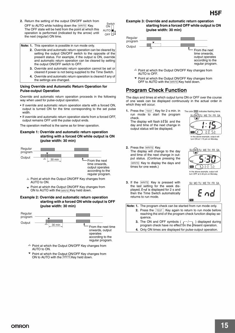
2. Return the setting of the output ON/OFF switch from
OFF to AUTO while holding down the Key.The OFF state will be held from the point at which thisoperation is performed (indicated by the arrow) untilthe next (regular) ON time.
Using Override and Automatic Return Operation for Pulse-output Operation
Override and automatic return operation proceeds in the followingway when used for pulse-output operation.
• If override and automatic return operation starts with a forced ON,output is turned ON for the time corresponding to the set pulsewidth.
• If override and automatic return operation starts from a forced OFF,output remains OFF until the pulse output ends.
The operation method is the same as for timer operation.
Example 1: Override and automatic return operation starting with a forced ON while output is ON (pulse width: 30 min)
Example 2: Override and automatic return operation starting with a forced ON while output is OFF (pulse width: 30 min)
Example 3: Override and automatic return operation starting from a forced OFF while output is ON (pulse width: 30 min)
Program Check FunctionThe days and times at which output turns ON or OFF over the courseof one week can be displayed continuously in the actual order inwhich they will occur.
1. Press the Key for 2 s min. inrun mode to start the programcheck.The display will flash test and theday and time of the next change inoutput status will be displayed.
2. Press the Key.The display will change to the dayand time of the next change in out-put status. (Continue pressing the
Key to display the days andtimes for one week.)
3. If the Key is pressed withthe last setting for the week dis-played, end is displayed for 2 s andthen the Time Switch automaticallyreturns to run mode.
Note: 1. This operation is possible in run mode only.2. Override and automatic return operation can be cleared by
setting the output ON/OFF switch to the opposite of thepresent status. For example, if the output is ON, overrideand automatic return operation can be cleared by settingthe output ON/OFF switch to OFF.
3. Override and automatic return operation cannot be set orcleared if power is not being supplied to the Time Switch.
4. Override and automatic return operation is cleared if any ofthe settings are changed.
WRITE ON
AUTO
OFF
Switch
30 minOutput
From the next time onwards, output operates according to the regular program.
Point at which the Output ON/OFF Key changes from AUTO to ON.
Point at which the Output ON/OFF Key changes from ON to AUTO with the Key held down.
Regular program
WRITE
30 minOutput
From the next time onwards, output operates according to the regular program.
Point at which the Output ON/OFF Key changes from AUTO to ON.
Point at which the Output ON/OFF Key changes from ON to AUTO with the Key held down.
Regular program
WRITE
Note: 1. The program check can be started from run mode only.2. Press the Key again to return to run mode before
reaching the end of the program check function display se-quence.
3. The ON and OFF symbols ( / ) displayed duringprogram check have no effect on the present operation.
4. Only ON times are displayed for pulse-output operation.
OutputFrom the next time onwards, output operates according to the regular program.
Point at which the Output ON/OFF Key changes from AUTO to OFF.
Point at which the Output ON/OFF Key changes from OFF to AUTO with the Key held down.
Regular program
WRITE
TEST
te st
1 15PM
PW
SU MO TU WE TH FR SA
In the above example, output will turn ON at 1:15 pm on Monday.
The color indicates flashing items.
WRITE
WRITE
te st
5 30PM
PW
SU MO TU WE TH FR SA
In the above example, output will turn OFF at 5:30 pm on Monday.
WRITE
e ndPW
SU MO TU WE TH FR SA
TEST
H5F
16
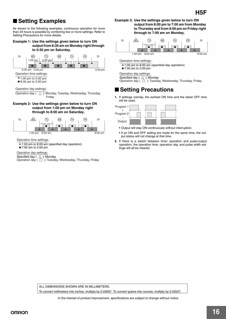
Setting ExamplesAs shown in the following examples, continuous operation for morethan 24 hours is possible by combining two or more settings. Refer toSetting Precautions for more details.
Example 1: Use the settings given below to turn ON output from 8:30 am on Monday right through to 0:30 pm on Saturday.
Example 2: Use the settings given below to turn ON output from 1:00 pm on Monday right through to 8:00 am on Saturday.
Example 3: Use the settings given below to turn ON output from 8:00 pm to 7:00 am from Monday to Thursday and from 8:00 pm on Friday right through to 7:00 am on Monday.
Setting Precautions1. If settings overlap, the earliest ON time and the latest OFF time
will be used.
• Output will stay ON continuously without interruption.
• If an ON and OFF setting are made for the same time, the out-put status will not change at that time.
2. If there is a switch between timer operation and pulse-outputoperation, the operation time, operation day, and pulse width set-tings will all be cleared.
SU MO TU WE TH FR SA
1:00 pm
2:00 pm
0:30 pm
0:30 pm8:30 am
1:00 pm to 0:30 pm8:30 am to 2:00 pm
Operation time settings:
Operation day settings:
Operation day ( ): Monday, Tuesday, Wednesday, Thursday, Friday
7:00 am
1:00 pm 8:00 am 8:00 am
2:00 pm
SU MO TU WE TH FR SA
1:00 pm to 8:00 am (specified day operation)7:00 am to 2:00 pm
Operation time settings:
Operation day settings:Specified day ( ): MondayOperation day ( ): Tuesday, Wednesday, Thursday, Friday
7:00 am
1:00 pm 8:00 am 8:00 am
2:00 pm
SU MO TU WE TH FR SA
1:00 pm to 8:00 am (specified day operation)7:00 am to 2:00 pm
Operation time settings:
Operation day settings:Specified day ( ): MondayOperation day ( ): Tuesday, Wednesday, Thursday, Friday
+Program 1
Program 2
Output
In the interest of product improvement, specifications are subject to change without notice.
ALL DIMENSIONS SHOWN ARE IN MILLIMETERS.
To convert millimeters into inches, multiply by 0.03937. To convert grams into ounces, multiply by 0.03527.
Terms and Conditions Agreement Read and understand this catalog. Please read and understand this catalog before purchasing the products. Please consult your OMRON representative if you have any questions or comments. Warranties. (a) Exclusive Warranty. Omron’s exclusive warranty is that the Products will be free from defects in materials and workmanship for a period of twelve months from the date of sale by Omron (or such other period expressed in writing by Omron). Omron disclaims all other warranties, express or implied. (b) Limitations. OMRON MAKES NO WARRANTY OR REPRESENTATION, EXPRESS OR IMPLIED, ABOUT NON-INFRINGEMENT, MERCHANTABILITY OR FITNESS FOR A PARTICULAR PURPOSE OF THE PRODUCTS. BUYER ACKNOWLEDGES THAT IT ALONE HAS DETERMINED THAT THE PRODUCTS WILL SUITABLY MEET THE REQUIREMENTS OF THEIR INTENDED USE. Omron further disclaims all warranties and responsibility of any type for claims or expenses based on infringement by the Products or otherwise of any intellectual property right. (c) Buyer Remedy. Omron’s sole obligation hereunder shall be, at Omron’s election, to (i) replace (in the form originally shipped with Buyer responsible for labor charges for removal or replacement thereof) the non-complying Product, (ii) repair the non-complying Product, or (iii) repay or credit Buyer an amount equal to the purchase price of the non-complying Product; provided that in no event shall Omron be responsible for warranty, repair, indemnity or any other claims or expenses regarding the Products unless Omron’s analysis confirms that the Products were properly handled, stored, installed and maintained and not subject to contamination, abuse, misuse or inappropriate modification. Return of any Products by Buyer must be approved in writing by Omron before shipment. Omron Companies shall not be liable for the suitability or unsuitability or the results from the use of Products in combination with any electrical or electronic components, circuits, system assemblies or any other materials or substances or environments. Any advice, recommendations or information given orally or in writing, are not to be construed as an amendment or addition to the above warranty. See http://www.omron.com/global/ or contact your Omron representative for published information. Limitation on Liability; Etc. OMRON COMPANIES SHALL NOT BE LIABLE FOR SPECIAL, INDIRECT, INCIDENTAL, OR CONSEQUENTIAL DAMAGES, LOSS OF PROFITS OR PRODUCTION OR COMMERCIAL LOSS IN ANY WAY CONNECTED WITH THE PRODUCTS, WHETHER SUCH CLAIM IS BASED IN CONTRACT, WARRANTY, NEGLIGENCE OR STRICT LIABILITY. Further, in no event shall liability of Omron Companies exceed the individual price of the Product on which liability is asserted. Suitability of Use. Omron Companies shall not be responsible for conformity with any standards, codes or regulations which apply to the combination of the Product in the Buyer’s application or use of the Product. At Buyer’s request, Omron will provide applicable third party certification documents identifying ratings and limitations of use which apply to the Product. This information by itself is not sufficient for a complete determination of the suitability of the Product in combination with the end product, machine, system, or other application or use. Buyer shall be solely responsible for determining appropriateness of the particular Product with respect to Buyer’s application, product or system. Buyer shall take application responsibility in all cases. NEVER USE THE PRODUCT FOR AN APPLICATION INVOLVING SERIOUS RISK TO LIFE OR PROPERTY OR IN LARGE QUANTITIES WITHOUT ENSURING THAT THE SYSTEM AS A WHOLE HAS BEEN DESIGNED TO ADDRESS THE RISKS, AND THAT THE OMRON PRODUCT(S) IS PROPERLY RATED AND INSTALLED FOR THE INTENDED USE WITHIN THE OVERALL EQUIPMENT OR SYSTEM. Programmable Products. Omron Companies shall not be responsible for the user’s programming of a programmable Product, or any consequence thereof. Performance Data. Data presented in Omron Company websites, catalogs and other materials is provided as a guide for the user in determining suitability and does not constitute a warranty. It may represent the result of Omron’s test conditions, and the user must correlate it to actual application requirements. Actual performance is subject to the Omron’s Warranty and Limitations of Liability. Change in Specifications. Product specifications and accessories may be changed at any time based on improvements and other reasons. It is our practice to change part numbers when published ratings or features are changed, or when significant construction changes are made. However, some specifications of the Product may be changed without any notice. When in doubt, special part numbers may be assigned to fix or establish key specifications for your application. Please consult with your Omron’s representative at any time to confirm actual specifications of purchased Product. Errors and Omissions. Information presented by Omron Companies has been checked and is believed to be accurate; however, no responsibility is assumed for clerical, typographical or proofreading errors or omissions.
2015.7
In the interest of product improvement, specifications are subject to change without notice.
OMRON Corporation Industrial Automation Company http://www.ia.omron.com/
(c)Copyright OMRON Corporation 2015 All Right Reserved.