Embed Size (px)
Citation preview
Digital Communications I:Modulation and Coding Course
Term 3 – 2008
Catharina Logothetis
Lecture 2
Lecture 2 2
Last time, we talked about:
Important features of digital communication systems
Some basic concepts and definitions such as as signal classification, spectral density, random process, linear systems and signal bandwidth.
Lecture 2 3
Today, we are going to talk about:
The first important step in any DCS:
Transforming the information source to a form compatible with a digital system
Lecture 2 4
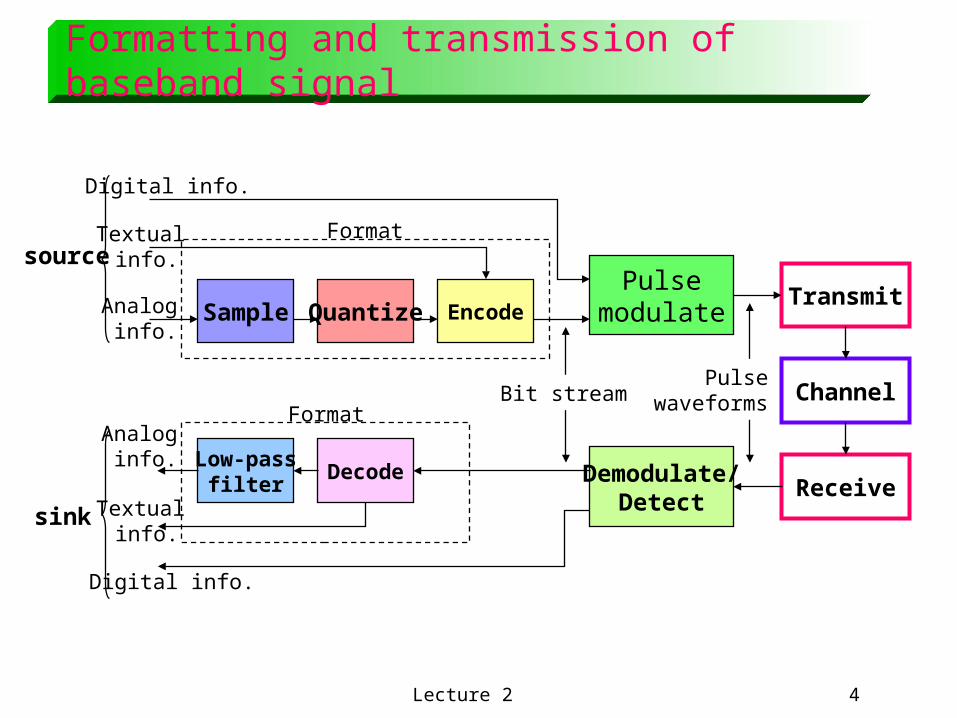
EncodeTransmit
PulsemodulateSample Quantize
Demodulate/Detect
Channel
ReceiveLow-pass
filterDecode
PulsewaveformsBit stream
Format
Format
Digital info.
Textual info.
Analog info.
Textual info.
Analog info.
Digital info.
source
sink
Formatting and transmission of baseband signal
Lecture 2 5
Format analog signals
To transform an analog waveform into a form that is compatible with a digital communication system, the following steps are taken:
1. Sampling
2. Quantization and encoding
3. Baseband transmission
Lecture 2 6
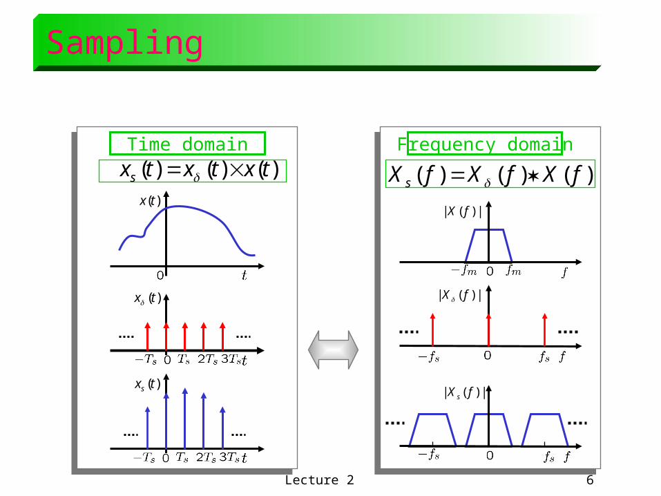
Sampling
Time domain Frequency domain
)()()( txtxtxs )()()( fXfXfX s
|)(| fX)(tx
|)(| fX
|)(| fX s
)(txs
)(tx
Lecture 2 7
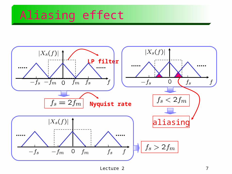
Aliasing effect
LP filter
Nyquist rate
aliasing

Lecture 2 8
Sampling theorem
Sampling theorem: A bandlimited signal with no spectral components beyond , can be uniquely determined by values sampled at
uniform intervals of
The sampling rate, is called Nyquist rate.
Sampling process
Analog signal
Pulse amplitudemodulated (PAM) signal
Lecture 2 9
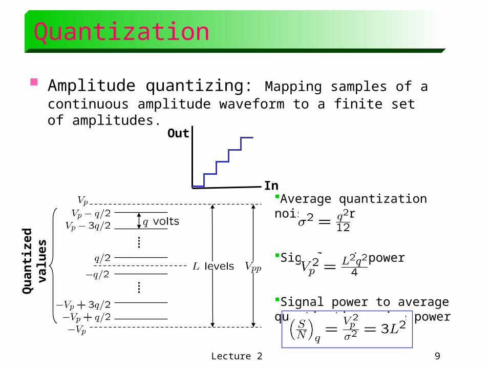
Quantization
Amplitude quantizing: Mapping samples of a continuous amplitude waveform to a finite set of amplitudes.
In
Out
Qu
anti
zed
valu
es
Average quantization noise power
Signal peak power
Signal power to average quantization noise power
Lecture 2 10
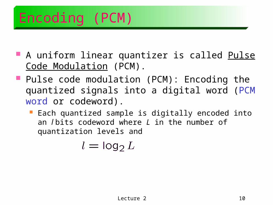
Encoding (PCM)
A uniform linear quantizer is called Pulse Code Modulation (PCM).
Pulse code modulation (PCM): Encoding the quantized signals into a digital word (PCM word or codeword). Each quantized sample is digitally encoded into an l bits
codeword where L in the number of quantization levels and
Lecture 2 11
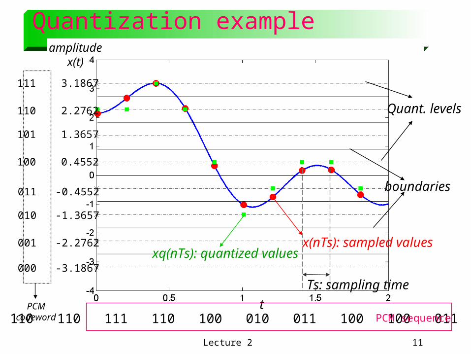
Quantization example
t
Ts: sampling time
x(nTs): sampled valuesxq(nTs): quantized values
boundaries
Quant. levels
111 3.1867
110 2.2762
101 1.3657
100 0.4552
011 -0.4552
010 -1.3657
001 -2.2762
000 -3.1867
PCMcodeword 110 110 111 110 100 010 011 100 100 011 PCM sequence
amplitudex(t)
Lecture 2 12
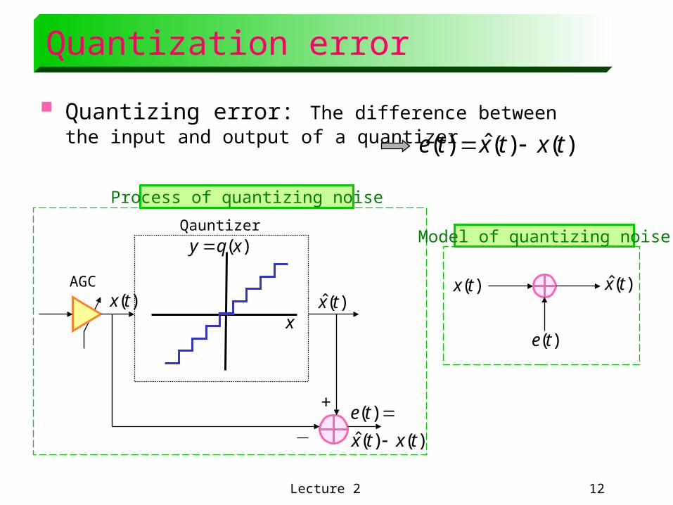
Quantization error
Quantizing error: The difference between the input and output of a quantizer )()(ˆ)( txtxte
+
)(tx )(ˆ tx
)()(ˆ
)(
txtx
te
AGC
x
)(xqy Qauntizer
Process of quantizing noise
)(tx )(ˆ tx
)(te
Model of quantizing noise
Lecture 2 13
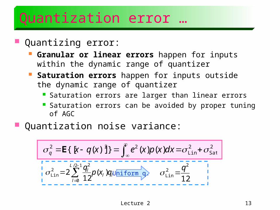
Quantization error …
Quantizing error: Granular or linear errors happen for inputs within the dynamic
range of quantizer Saturation errors happen for inputs outside the dynamic
range of quantizer Saturation errors are larger than linear errors Saturation errors can be avoided by proper tuning of AGC
Quantization noise variance:
2Sat
2Lin
222 )()(})]({[
dxxpxexqxq E
ll
L
l
l qxpq
)(12
212/
0
22Lin
Uniform q.12
22Lin
q
Lecture 2 14
Uniform and non-uniform quant. Uniform (linear) quantizing:
No assumption about amplitude statistics and correlation properties of the input.
Not using the user-related specifications Robust to small changes in input statistic by not finely tuned to a
specific set of input parameters Simple implementation
Application of linear quantizer: Signal processing, graphic and display applications, process
control applications Non-uniform quantizing:
Using the input statistics to tune quantizer parameters Larger SNR than uniform quantizing with same number of levels Non-uniform intervals in the dynamic range with same quantization
noise variance Application of non-uniform quantizer:
Commonly used for speech
Lecture 2 15
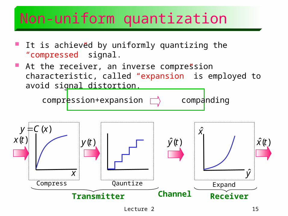
Non-uniform quantization
It is achieved by uniformly quantizing the “compressed” signal. At the receiver, an inverse compression characteristic, called
“expansion” is employed to avoid signal distortion.
compression+expansion companding
)(ty)(tx )(ˆ ty )(ˆ tx
x
)(xCy x
yCompress Qauntize
ChannelExpand
Transmitter Receiver
Lecture 2 16
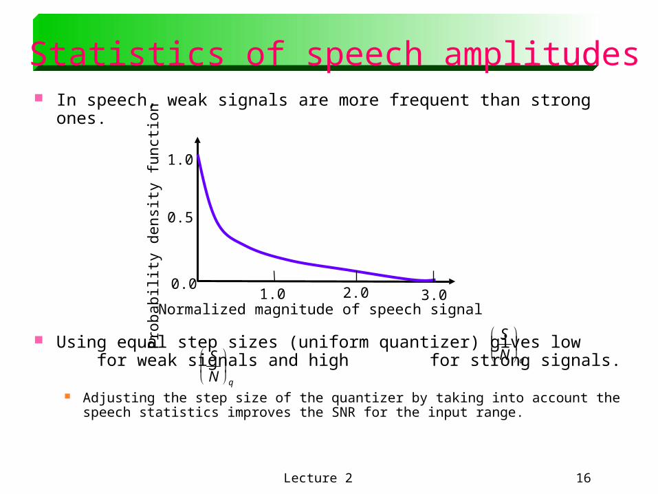
Statistics of speech amplitudes In speech, weak signals are more frequent than strong ones.
Using equal step sizes (uniform quantizer) gives low for weak signals and high for strong signals.
Adjusting the step size of the quantizer by taking into account the speech statistics improves the SNR for the input range.
0.0
1.0
0.5
1.0 2.0 3.0Normalized magnitude of speech signalP
roba
bili
ty d
ensi
ty f
unct
ion
qN
S
qN
S
Lecture 2 17
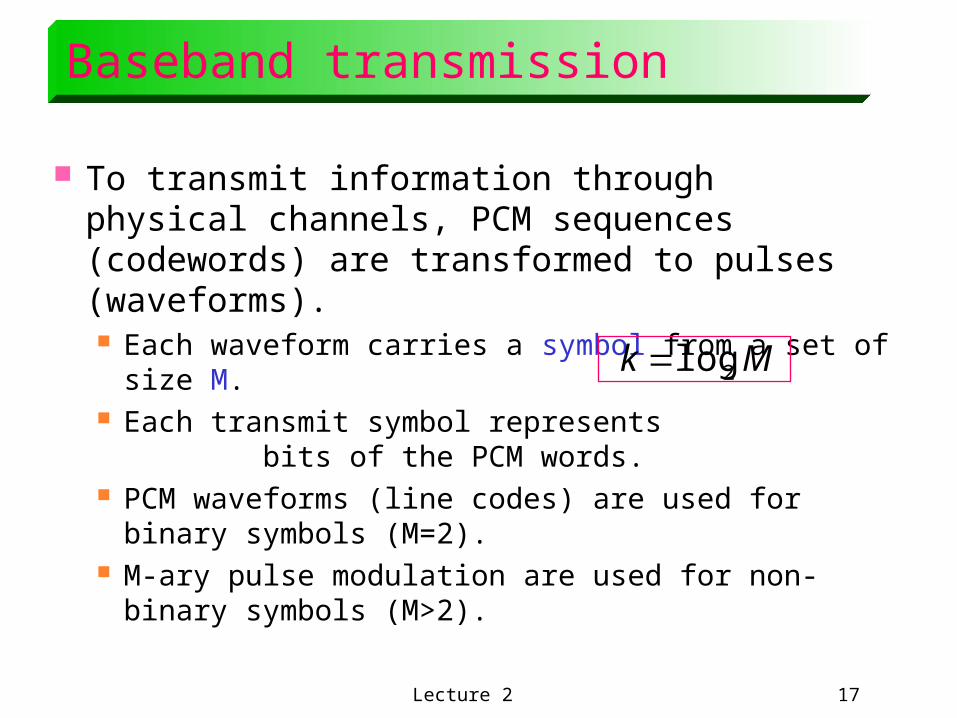
Baseband transmission
To transmit information through physical channels, PCM sequences (codewords) are transformed to pulses (waveforms). Each waveform carries a symbol from a set of size M. Each transmit symbol represents bits of
the PCM words. PCM waveforms (line codes) are used for binary
symbols (M=2). M-ary pulse modulation are used for non-binary
symbols (M>2).
Mk 2log
Lecture 2 18
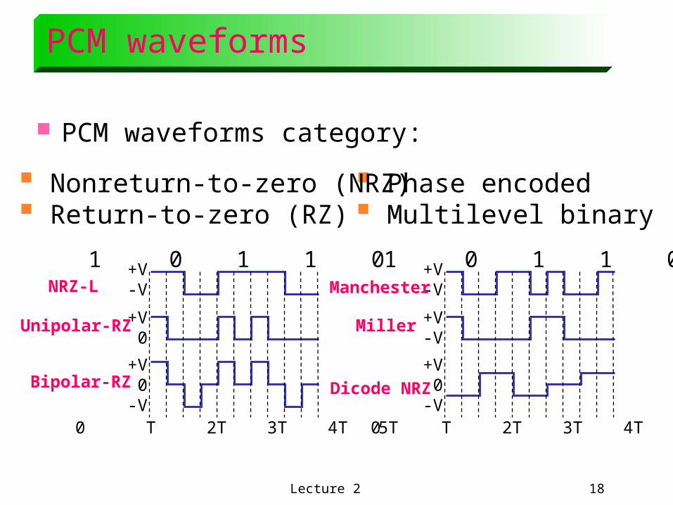
PCM waveforms
PCM waveforms category:
Phase encoded Multilevel binary
Nonreturn-to-zero (NRZ) Return-to-zero (RZ)
1 0 1 1 0
0 T 2T 3T 4T 5T
+V-V
+V0
+V0
-V
1 0 1 1 0
0 T 2T 3T 4T 5T
+V-V
+V-V
+V0
-V
NRZ-L
Unipolar-RZ
Bipolar-RZ
Manchester
Miller
Dicode NRZ
Lecture 2 19
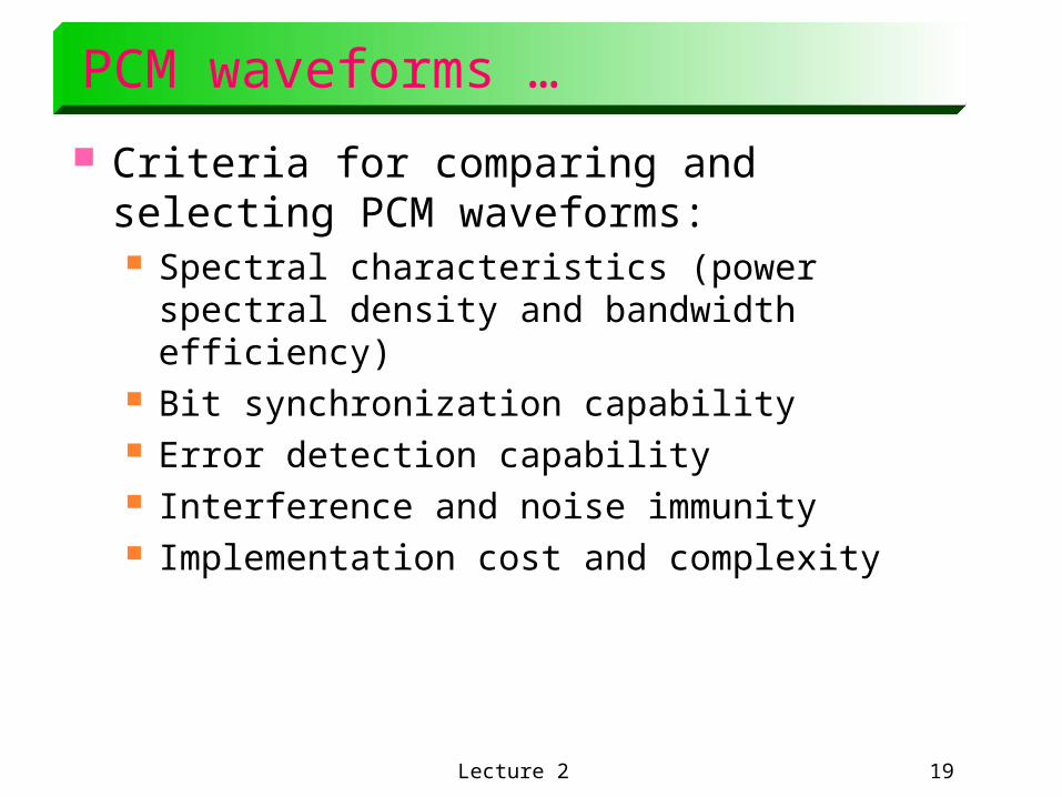
PCM waveforms …
Criteria for comparing and selecting PCM waveforms: Spectral characteristics (power spectral density and
bandwidth efficiency) Bit synchronization capability Error detection capability Interference and noise immunity Implementation cost and complexity
Lecture 2 20
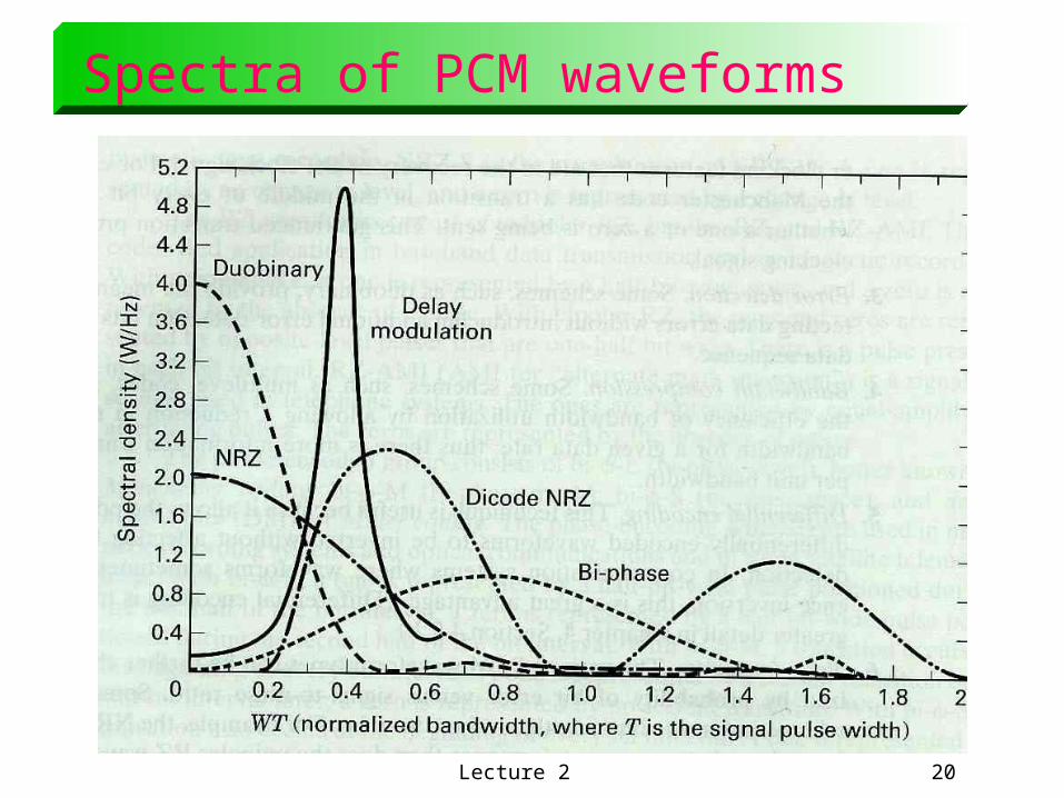
Spectra of PCM waveforms
Lecture 2 21
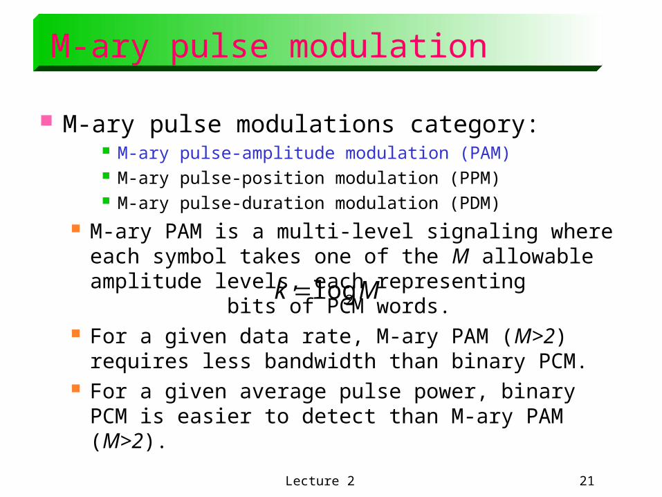
M-ary pulse modulation
M-ary pulse modulations category: M-ary pulse-amplitude modulation (PAM) M-ary pulse-position modulation (PPM) M-ary pulse-duration modulation (PDM)
M-ary PAM is a multi-level signaling where each symbol takes one of the M allowable amplitude levels, each representing bits of PCM words.
For a given data rate, M-ary PAM (M>2) requires less bandwidth than binary PCM.
For a given average pulse power, binary PCM is easier to detect than M-ary PAM (M>2).
Mk 2log
Lecture 2 22
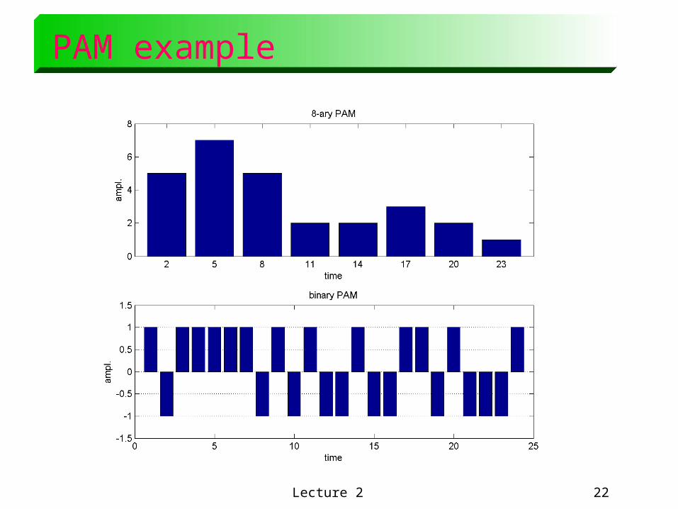
PAM example


![[PPT]Modulation, Demodulation and Coding Course · Web viewDigital Communications I: Modulation and Coding Course Term 3 - 2008 Catharina Logothetis Lecture 8 Last time we talked](https://img.pdfslide.us/doc/110x75/5af3a5bb7f8b9a4d4d8c6d55/pptmodulation-demodulation-and-coding-viewdigital-communications-i-modulation.jpg)