Embed Size (px)
Citation preview
APPLIED ENGINEERING PRODUCTS104 John W. Murphy Drive • P.O. Box 510 • New Haven, CT 06513
(203) 776-2813 • FAX (203) 776-8294
www.aep.us • e-mail: [email protected]
SSMBSSLBSSMC
DIGITAL CATALOG
MicrominiatureCoaxialConnectors
SSMB/SSLB/SSMC Microminiature ConnectorsClick at the bottom of any page to go to the AEP website.
Contents
Introduction . . . . . . . . . . . . . . . . . . . . . . . . . . . . . . . . . . . . . . . . . . . . . . . . . . . . . . . . . . 2
Technical Information
Special features and options. . . . . . . . . . . . . . . . . . . . . . . . . . . . . . . . . . . . . . . . . . . . . 3
Mated-pair dimensions . . . . . . . . . . . . . . . . . . . . . . . . . . . . . . . . . . . . . . . . . . . . . . . . . 4
Interfaces and specifications . . . . . . . . . . . . . . . . . . . . . . . . . . . . . . . . . . . . . . . . . . . . . 5
VSWR data. . . . . . . . . . . . . . . . . . . . . . . . . . . . . . . . . . . . . . . . . . . . . . . . . . . . . . . . . . . 6
SSMB Series
Cable connectors . . . . . . . . . . . . . . . . . . . . . . . . . . . . . . . . . . . . . . . . . . . . . . . . . . . . . . 7
Bulkhead mounted receptacles . . . . . . . . . . . . . . . . . . . . . . . . . . . . . . . . . . . . . . . . . . . 9
P.C. board receptacles . . . . . . . . . . . . . . . . . . . . . . . . . . . . . . . . . . . . . . . . . . . . . . . . . 10
Panel mounted receptacles . . . . . . . . . . . . . . . . . . . . . . . . . . . . . . . . . . . . . . . . . . . . . 14
Adapters . . . . . . . . . . . . . . . . . . . . . . . . . . . . . . . . . . . . . . . . . . . . . . . . . . . . . . . . . . . 14
SSLB Series
Cable connectors . . . . . . . . . . . . . . . . . . . . . . . . . . . . . . . . . . . . . . . . . . . . . . . . . . . . . 15
Vibration-proof float mount plugs. . . . . . . . . . . . . . . . . . . . . . . . . . . . . . . . . . . . . . . . 16
Bulkhead mounted receptacles . . . . . . . . . . . . . . . . . . . . . . . . . . . . . . . . . . . . . . . . . . 17
P.C. board receptacles . . . . . . . . . . . . . . . . . . . . . . . . . . . . . . . . . . . . . . . . . . . . . . . . . 18
SSMC Series
Cable connectors . . . . . . . . . . . . . . . . . . . . . . . . . . . . . . . . . . . . . . . . . . . . . . . . . . . . . 20
Bulkhead mounted receptacles . . . . . . . . . . . . . . . . . . . . . . . . . . . . . . . . . . . . . . . . . . 22
P.C. board receptacles . . . . . . . . . . . . . . . . . . . . . . . . . . . . . . . . . . . . . . . . . . . . . . . . . 23
Panel mounted receptacles . . . . . . . . . . . . . . . . . . . . . . . . . . . . . . . . . . . . . . . . . . . . . 27
Adapters . . . . . . . . . . . . . . . . . . . . . . . . . . . . . . . . . . . . . . . . . . . . . . . . . . . . . . . . . . . 27
P.C. Board Mounted Cable Terminations . . . . . . . . . . . . . . . . . . . . . . . . . . . . . . . . . . 28
Assembly Tooling . . . . . . . . . . . . . . . . . . . . . . . . . . . . . . . . . . . . . . . . . . . . . . . . . . . . 29
Index by AEP Part Number . . . . . . . . . . . . . . . . . . . . . . . . . . . . . . . . . . . . . . . . . . . . . 30
About AEP . . . . . . . . . . . . . . . . . . . . . . . . . . . . . . . . . . . . . . . . . . . . . . . . . . . . . . . . . . 31
(Click on any line to jump to the page)
(203) 776-2813 • FAX (203) 776-8294APPLIED ENGINEERING PRODUCTS
www.aep.us • [email protected] 1
SSMB/SSLB/SSMC Microminiature Connectors
SSMB (snap-on mating), SSLB (slide-on mating), and SSMC (screw-on mating) microminiatureconnectors from AEP can be the answer you’re looking for in your applications that are shorton space but need to be long on performance.
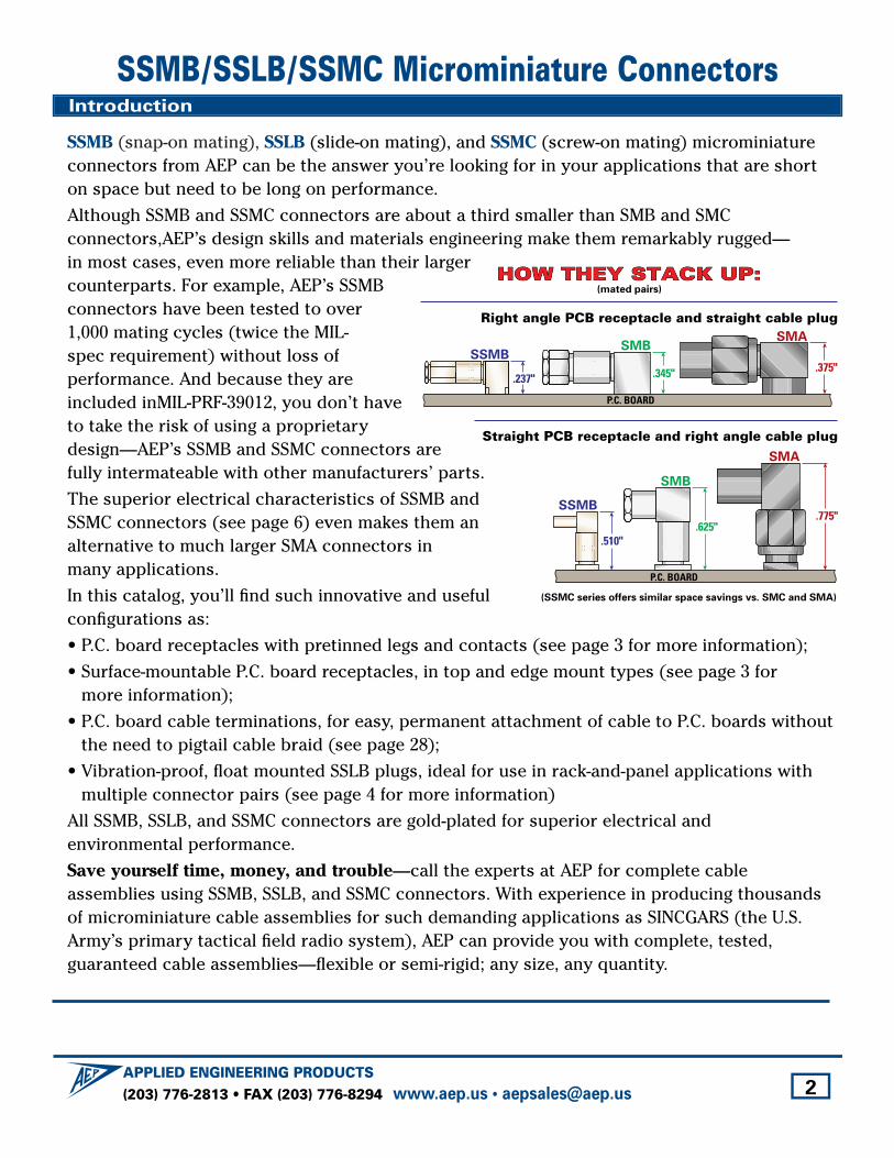
Although SSMB and SSMC connectors are about a third smaller than SMB and SMC connectors,AEP’s design skills and materials engineering make them remarkably rugged—in most cases, even more reliable than their largercounterparts. For example, AEP’s SSMBconnectors have been tested to over1,000 mating cycles (twice the MIL-spec requirement) without loss of performance. And because they areincluded inMIL-PRF-39012, you don’t haveto take the risk of using a proprietarydesign—AEP’s SSMB and SSMC connectors arefully intermateable with other manufacturers’ parts.
The superior electrical characteristics of SSMB andSSMC connectors (see page 6) even makes them an alternative to much larger SMA connectors in many applications.
In this catalog, you’ll find such innovative and usefulconfigurations as:
• P.C. board receptacles with pretinned legs and contacts (see page 3 for more information);
• Surface-mountable P.C. board receptacles, in top and edge mount types (see page 3 for more information);
• P.C. board cable terminations, for easy, permanent attachment of cable to P.C. boards withoutthe need to pigtail cable braid (see page 28);
• Vibration-proof, float mounted SSLB plugs, ideal for use in rack-and-panel applications withmultiple connector pairs (see page 4 for more information)
All SSMB, SSLB, and SSMC connectors are gold-plated for superior electrical and environmental performance.
Save yourself time, money, and trouble—call the experts at AEP for complete cable assemblies using SSMB, SSLB, and SSMC connectors. With experience in producing thousandsof microminiature cable assemblies for such demanding applications as SINCGARS (the U.S.Army’s primary tactical field radio system), AEP can provide you with complete, tested, guaranteed cable assemblies—flexible or semi-rigid; any size, any quantity.
.345"
SMBSMA
.237"
SSMB
P.C. BOARD
.375"
SMB
SMA
SSMB
P.C. BOARD
.625".510"
.775"
Right angle PCB receptacle and straight cable plug
HOW THEY STACK UP:HOW THEY STACK UP:HOW THEY STACK UP:(mated pairs)
(SSMC series offers similar space savings vs. SMC and SMA)
Straight PCB receptacle and right angle cable plug
Introduction
(203) 776-2813 • FAX (203) 776-8294APPLIED ENGINEERING PRODUCTS
www.aep.us • [email protected] 2
(203) 776-2813 • FAX (203) 776-8294APPLIED ENGINEERING PRODUCTS
www.aep.us • [email protected] 3
AEP pretinned P.C. board receptacles are shipped with a tightly-controlled layer of solder on the legs and center conductor, eliminating gold embrittlement in solder joints. Nickel-plated connectors with pretinned legs have the solderability of gold or silver-plated connectors at lower cost.
Computer-controlled, automated solder-dipping equipment and custom fixturingensure precise, consistent coverage to AEP standard specification (see above), or customer-specified requirements.Tinned areas meet the solderability requirements of MIL-STD-202, Method 208 aftereight hours steam aging. Pretinned legs are available on most P.C. board receptaclesin this catalog—see product pages for part numbers.
P.C. board
Pan
el
P.C. board
Panel
P.C
. bo
ard
Panel
Pan
el
P.C
. b
oard
P.C
. bo
ard
P.C. boardP.C. board
SSMB/SSLB/SSMC Features and Options
Solder(center conductor)
Printed circuit board
Solder (leg) (typ.)
Ground trace
Ground trace
Signal trace
Solder(bottom legs andcenter conductor)
Solder(top legs)
Printed circuit board
P.C. boardSolder (center conductor)
Solder (legs)
Printed circuit boardGround trace
Ground trace
Signal trace
Solder (leg)
Solder (leg)
Surface Mount P.C. Board Receptacles
P.C. Board Receptacles with Standoff Legs
P.C. Board Receptacles with Pretinned Legs and Contacts
Edge mount Top mount
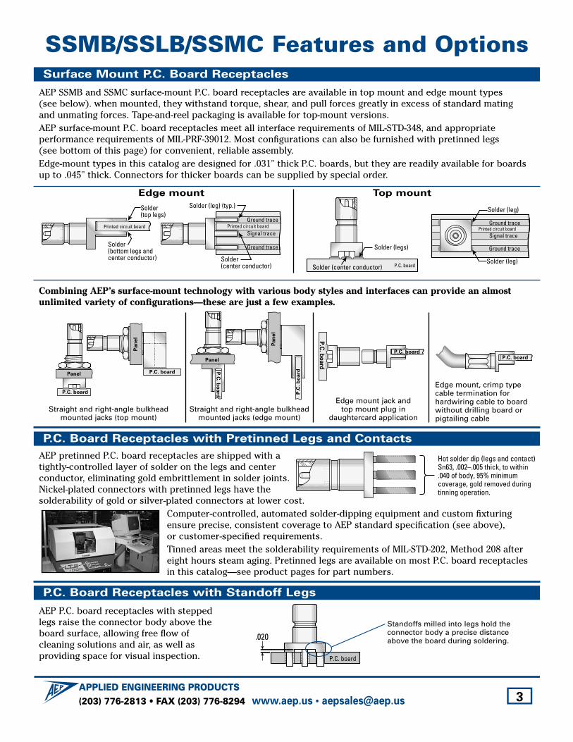
AEP SSMB and SSMC surface-mount P.C. board receptacles are available in top mount and edge mount types (see below). when mounted, they withstand torque, shear, and pull forces greatly in excess of standard mating and unmating forces. Tape-and-reel packaging is available for top-mount versions.AEP surface-mount P.C. board receptacles meet all interface requirements of MIL-STD-348, and appropriate performance requirements of MIL-PRF-39012. Most configurations can also be furnished with pretinned legs (see bottom of this page) for convenient, reliable assembly.Edge-mount types in this catalog are designed for .031" thick P.C. boards, but they are readily available for boardsup to .045" thick. Connectors for thicker boards can be supplied by special order.
Combining AEP’s surface-mount technology with various body styles and interfaces can provide an almostunlimited variety of configurations—these are just a few examples.
Straight and right-angle bulkhead mounted jacks (edge mount)
Edge mount jack and top mount plug in
daughtercard application
Edge mount, crimp typecable termination for hardwiring cable to boardwithout drilling board or pigtailing cable
Straight and right-angle bulkheadmounted jacks (top mount)
AEP P.C. board receptacles with steppedlegs raise the connector body above theboard surface, allowing free flow of cleaning solutions and air, as well as providing space for visual inspection. P.C. board
.020
Standoffs milled into legs hold theconnector body a precise distanceabove the board during soldering.
Hot solder dip (legs and contact)Sn63, .002–.005 thick, to within .040 of body, 95% minimum coverage, gold removed during tinning operation.
(203) 776-2813 • FAX (203) 776-8294APPLIED ENGINEERING PRODUCTS
www.aep.us • [email protected] 4
SSMB/SSLB/SSMC Features and Options
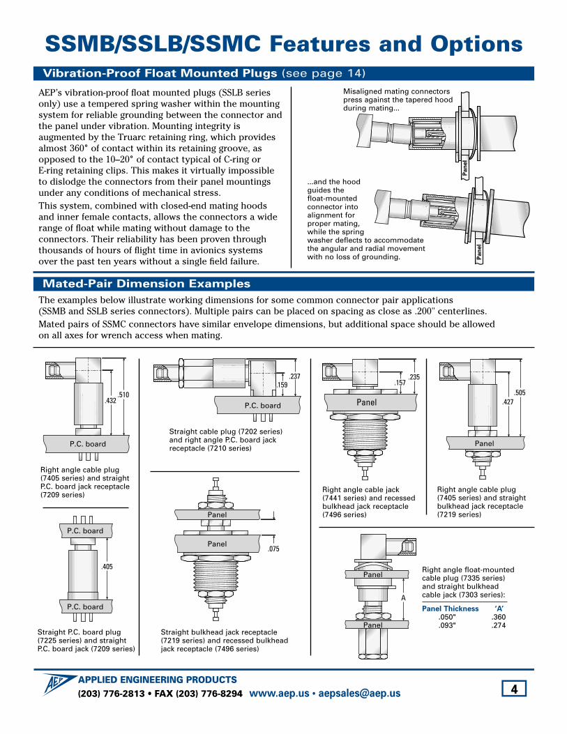
AEP’s vibration-proof float mounted plugs (SSLB seriesonly) use a tempered spring washer within the mounting system for reliable grounding between the connector andthe panel under vibration. Mounting integrity is augmented by the Truarc retaining ring, which providesalmost 360˚ of contact within its retaining groove, asopposed to the 10–20˚ of contact typical of C-ring or E-ring retaining clips. This makes it virtually impossibleto dislodge the connectors from their panel mountingsunder any conditions of mechanical stress.This system, combined with closed-end mating hoodsand inner female contacts, allows the connectors a widerange of float while mating without damage to the connectors. Their reliability has been proven throughthousands of hours of flight time in avionics systemsover the past ten years without a single field failure.
Vibration-Proof Float Mounted Plugs (see page 14)
Mated-Pair Dimension Examples
Pa
ne
l
Pa
ne
l
Misaligned mating connectorspress against the tapered hoodduring mating...
...and the hood guides the float-mounted connector into alignment for proper mating, while the spring washer deflects to accommodatethe angular and radial movement with no loss of grounding.
The examples below illustrate working dimensions for some common connector pair applications (SSMB and SSLB series connectors). Multiple pairs can be placed on spacing as close as .200" centerlines.Mated pairs of SSMC connectors have similar envelope dimensions, but additional space should be allowed on all axes for wrench access when mating.
Right angle cable plug (7405 series) and straightP.C. board jack receptacle(7209 series)
Right angle cable plug (7405 series) and straight bulkhead jack receptacle (7219 series)
.405
P.C. board
P.C. board
.075
Panel
Panel
A
Panel
Panel
.432.510
P.C. board
.159.237
P.C. board
.157.235
Panel .427.505
Panel
Straight cable plug (7202 series) and right angle P.C. board jackreceptacle (7210 series)
Right angle cable jack (7441 series) and recessedbulkhead jack receptacle (7496 series)
Straight bulkhead jack receptacle (7219 series) and recessed bulkhead jack receptacle (7496 series)
Straight P.C. board plug(7225 series) and straightP.C. board jack (7209 series)
Right angle float-mountedcable plug (7335 series)and straight bulkheadcable jack (7303 series):
Panel Thickness ‘A’.050" .360.093" .274
(203) 776-2813 • FAX (203) 776-8294APPLIED ENGINEERING PRODUCTS
www.aep.us • [email protected] 5
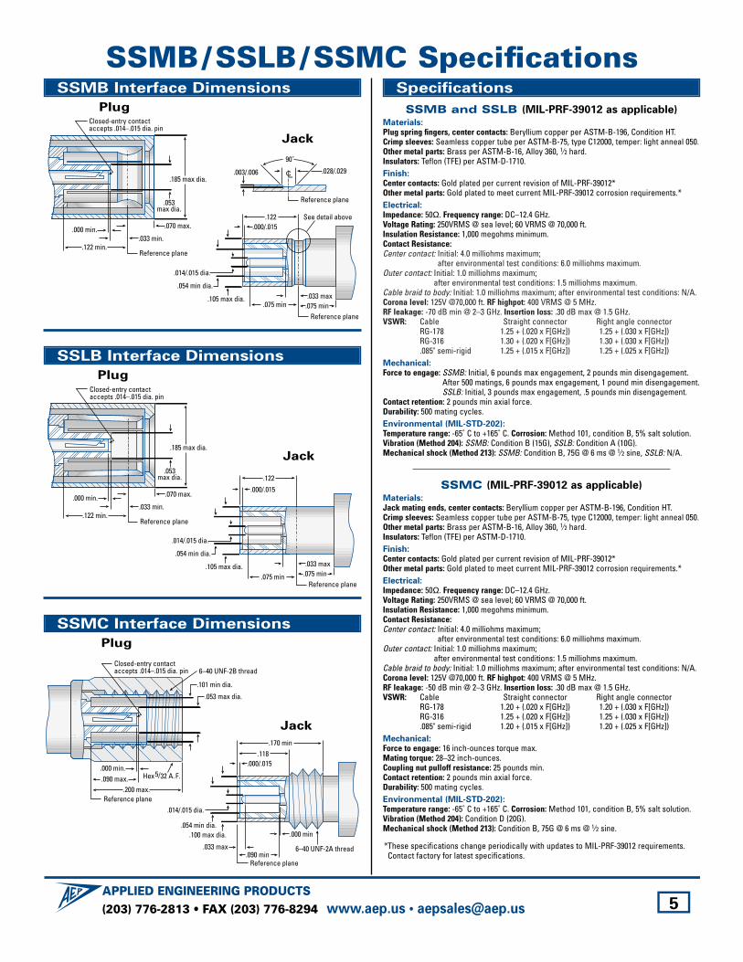
SSMB/SSLB /SSMC SpecificationsSSMB Interface Dimensions
Plug
Jack
Jack
Jack
SSLB Interface Dimensions
Plug
SSMC Interface Dimensions
Plug
.185 max dia.
Closed-entry contactaccepts .014–.015 dia. pin
.053max dia.
.070 max.
Reference plane
.000 min..033 min.
.122 min.
90˚
.105 max dia. .033 max.054 min dia.
.014/.015 dia.
.000/.015
Reference plane
.122 See detail above
.075 min
CL .028/.029
.075 min
.003/.006
Reference plane
.185 max dia.
Closed-entry contactaccepts .014–.015 dia. pin
.053max dia.
.070 max.
Reference plane
.000 min..033 min.
.122 min.
.033 max
.000/.015
.122
.075 min.075 minReference plane
.105 max dia.
.054 min dia.
.014/.015 dia.
.101 min dia.
Closed-entry contactaccepts .014–.015 dia. pin
.053 max dia.
6–40 UNF-2B thread
Reference plane
.000 min..090 max.
.200 max.
Hex 5/32 A. F.
.100 max dia. .000 min.054 min dia.
.014/.015 dia.
.000/.015
.033 max
.118.170 min
.090 minReference plane
6–40 UNF-2A thread
Specifications
SSMB and SSLB (MIL-PRF-39012 as applicable)Materials:Plug spring fingers, center contacts: Beryllium copper per ASTM-B-196, Condition HT. Crimp sleeves: Seamless copper tube per ASTM-B-75, type C12000, temper: light anneal 050. Other metal parts: Brass per ASTM-B-16, Alloy 360, 1⁄2 hard.Insulators: Teflon (TFE) per ASTM-D-1710.Finish:Center contacts: Gold plated per current revision of MIL-PRF-39012*Other metal parts: Gold plated to meet current MIL-PRF-39012 corrosion requirements.*Electrical:Impedance: 50Ω. Frequency range: DC–12.4 GHz. Voltage Rating: 250VRMS @ sea level; 60 VRMS @ 70,000 ft.Insulation Resistance: 1,000 megohms minimum.Contact Resistance:Center contact: Initial: 4.0 milliohms maximum;
after environmental test conditions: 6.0 milliohms maximum.Outer contact: Initial: 1.0 milliohms maximum;
after environmental test conditions: 1.5 milliohms maximum.Cable braid to body: Initial: 1.0 milliohms maximum; after environmental test conditions: N/A.Corona level: 125V @70,000 ft. RF highpot: 400 VRMS @ 5 MHz.RF leakage: -70 dB min @ 2–3 GHz. Insertion loss: .30 dB max @ 1.5 GHz.VSWR: Cable Straight connector Right angle connector
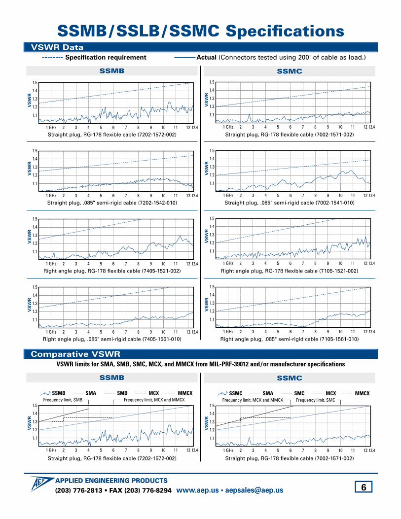
RG-178 1.25 + (.020 x F[GHz]) 1.25 + (.030 x F[GHz])RG-316 1.30 + (.020 x F[GHz]) 1.30 + (.030 x F[GHz]).085" semi-rigid 1.25 + (.015 x F[GHz]) 1.25 + (.025 x F[GHz])
Mechanical:Force to engage: SSMB: Initial, 6 pounds max engagement, 2 pounds min disengagement.
After 500 matings, 6 pounds max engagement, 1 pound min disengagement.SSLB: Initial, 3 pounds max engagement, .5 pounds min disengagement.
Contact retention: 2 pounds min axial force.Durability: 500 mating cycles.Environmental (MIL-STD-202):Temperature range: -65˚ C to +165˚ C. Corrosion: Method 101, condition B, 5% salt solution.Vibration (Method 204): SSMB: Condition B (15G), SSLB: Condition A (10G).Mechanical shock (Method 213): SSMB: Condition B, 75G @ 6 ms @ 1⁄2 sine, SSLB: N/A.
SSMC (MIL-PRF-39012 as applicable)Materials:Jack mating ends, center contacts: Beryllium copper per ASTM-B-196, Condition HT. Crimp sleeves: Seamless copper tube per ASTM-B-75, type C12000, temper: light anneal 050. Other metal parts: Brass per ASTM-B-16, Alloy 360, 1⁄2 hard.Insulators: Teflon (TFE) per ASTM-D-1710.Finish:Center contacts: Gold plated per current revision of MIL-PRF-39012*Other metal parts: Gold plated to meet current MIL-PRF-39012 corrosion requirements.*Electrical:Impedance: 50Ω. Frequency range: DC–12.4 GHz. Voltage Rating: 250VRMS @ sea level; 60 VRMS @ 70,000 ft.Insulation Resistance: 1,000 megohms minimum.Contact Resistance:Center contact: Initial: 4.0 milliohms maximum;
after environmental test conditions: 6.0 milliohms maximum.Outer contact: Initial: 1.0 milliohms maximum;
after environmental test conditions: 1.5 milliohms maximum.Cable braid to body: Initial: 1.0 milliohms maximum; after environmental test conditions: N/A.Corona level: 125V @70,000 ft. RF highpot: 400 VRMS @ 5 MHz.RF leakage: -50 dB min @ 2–3 GHz. Insertion loss: .30 dB max @ 1.5 GHz.VSWR: Cable Straight connector Right angle connector
RG-178 1.20 + (.020 x F[GHz]) 1.20 + (.030 x F[GHz])RG-316 1.25 + (.020 x F[GHz]) 1.25 + (.030 x F[GHz]).085" semi-rigid 1.20 + (.015 x F[GHz]) 1.20 + (.025 x F[GHz])
Mechanical:Force to engage: 16 inch-ounces torque max.Mating torque: 28–32 inch-ounces.Coupling nut pulloff resistance: 25 pounds min.Contact retention: 2 pounds min axial force.Durability: 500 mating cycles.Environmental (MIL-STD-202):Temperature range: -65˚ C to +165˚ C. Corrosion: Method 101, condition B, 5% salt solution.Vibration (Method 204): Condition D (20G).Mechanical shock (Method 213): Condition B, 75G @ 6 ms @ 1⁄2 sine.
*These specifications change periodically with updates to MIL-PRF-39012 requirements.Contact factory for latest specifications.
(203) 776-2813 • FAX (203) 776-8294APPLIED ENGINEERING PRODUCTS
www.aep.us • [email protected]
Frequency limit, SMB
VS
WR
1.1
21 GHz 3 4 5 6 7 8 9 10 11 12 12.4
1.2
1.3
1.4
1.5
SMBSMASSMB MCXFrequency limit, MCX and MMCX
MMCX
6
SSMB/SSLB /SSMC SpecificationsVSWR Data
VS
WR
1.1
21 GHz 3 4 5 6 7 8 9 10 11 12 12.4
1.2
1.3
1.4
1.5
VS
WR
1.1
21 GHz 3 4 5 6 7 8 9 10 11 12 12.4
1.2
1.3
1.4
1.5
Straight plug, RG-178 flexible cable (7202-1572-002) Straight plug, RG-178 flexible cable (7002-1571-002)
Frequency limit, SMC
VS
WR
1.1
21 GHz 3 4 5 6 7 8 9 10 11 12 12.4
1.2
1.3
1.4
1.5Frequency limit, MCX and MMCX
SMCSMASSMC MCX MMCX
Straight plug, RG-178 flexible cable (7202-1572-002) Straight plug, RG-178 flexible cable (7002-1571-002)
VS
WR
1.1
21 GHz 3 4 5 6 7 8 9 10 11 12 12.4
1.2
1.3
1.4
1.5
VS
WR
1.1
21 GHz 3 4 5 6 7 8 9 10 11 12 12.4
1.2
1.3
1.4
1.5
Straight plug, .085" semi-rigid cable (7202-1542-010) Straight plug, .085" semi-rigid cable (7002-1541-010)
VS
WR
1.1
21 GHz 3 4 5 6 7 8 9 10 11 12 12.4
1.2
1.3
1.4
1.5
VS
WR
1.1
21 GHz 3 4 5 6 7 8 9 10 11 12 12.4
1.2
1.3
1.4
1.5
Right angle plug, RG-178 flexible cable (7405-1521-002) Right angle plug, RG-178 flexible cable (7105-1521-002)
VS
WR
1.1
21 GHz 3 4 5 6 7 8 9 10 11 12 12.4
1.2
1.3
1.4
1.5
VS
WR
1.1
21 GHz 3 4 5 6 7 8 9 10 11 12 12.4
1.2
1.3
1.4
1.5
Right angle plug, .085" semi-rigid cable (7405-1561-010) Right angle plug, .085" semi-rigid cable (7105-1561-010)
SSMB SSMC
Specification requirement Actual (Connectors tested using 200' of cable as load.)
Comparative VSWR
SSMB SSMC
VSWR limits for SMA, SMB, SMC, MCX, and MMCX from MIL-PRF-39012 and/or manufacturer specifications
(203) 776-2813 • FAX (203) 776-8294APPLIED ENGINEERING PRODUCTS
www.aep.us • [email protected] 7
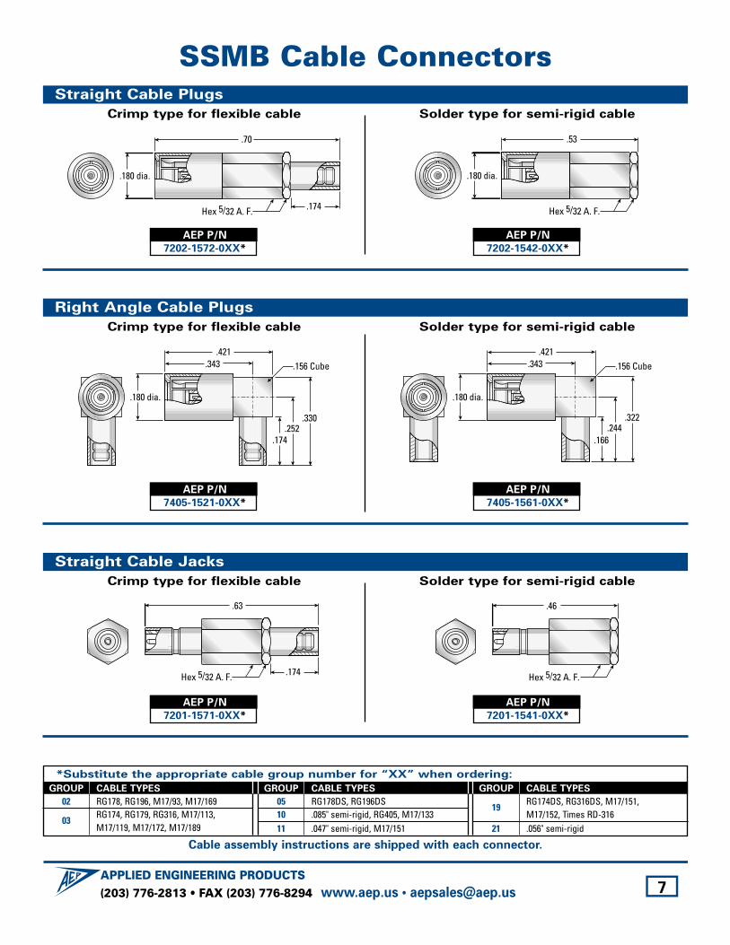
SSMB Cable Connectors
*Substitute the appropriate cable group number for “XX” when ordering:
Straight Cable Plugs
Crimp type for flexible cable Solder type for semi-rigid cable
.53
Hex 5/32 A. F.
.180 dia.
.174
.70
Hex 5/32 A. F.
.180 dia.
AEP P/N
7202-1572-0XX*
AEP P/N
7202-1542-0XX*
Straight Cable Jacks
Crimp type for flexible cable Solder type for semi-rigid cable
.46
Hex 5/32 A. F..174
.63
Hex 5/32 A. F.
AEP P/N
7201-1571-0XX*
AEP P/N
7201-1541-0XX*
Right Angle Cable Plugs
Crimp type for flexible cable Solder type for semi-rigid cable
.166.244
.322
.421.343
.180 dia.
.156 Cube.421
.343
.174.252
.330
.180 dia.
.156 Cube
AEP P/N
7405-1521-0XX*
AEP P/N
7405-1561-0XX*
GROUP CABLE TYPES
02 RG178, RG196, M17/93, M17/169
03RG174, RG179, RG316, M17/113, M17/119, M17/172, M17/189
GROUP CABLE TYPES
05 RG178DS, RG196DS10 .085" semi-rigid, RG405, M17/13311 .047" semi-rigid, M17/151
GROUP CABLE TYPES
19RG174DS, RG316DS, M17/151,M17/152, Times RD-316
21 .056" semi-rigid
Cable assembly instructions are shipped with each connector.
(203) 776-2813 • FAX (203) 776-8294APPLIED ENGINEERING PRODUCTS
www.aep.us • [email protected] 8
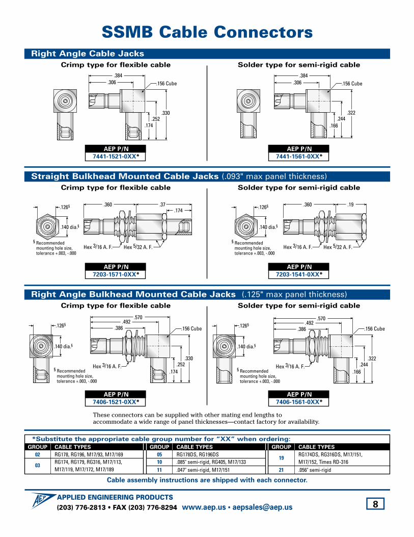
SSMB Cable ConnectorsRight Angle Cable Jacks
Crimp type for flexible cable Solder type for semi-rigid cable
.166.244
.322
.156 Cube.384
.306.384
.306
.174.252
.330
.156 Cube
AEP P/N
7441-1521-0XX*
AEP P/N
7441-1561-0XX*
Straight Bulkhead Mounted Cable Jacks (.093" max panel thickness)Crimp type for flexible cable Solder type for semi-rigid cable
.360 .19
Hex 5/32 A. F.Hex 3/16 A. F.
.140 dia.§
.126§
§ Recommendedmounting hole size,tolerance +.003, -.000
.140 dia.§
.126§
§ Recommendedmounting hole size,tolerance +.003, -.000
.174.360 .37
Hex 5/32 A. F.Hex 3/16 A. F.
AEP P/N
7203-1571-0XX*
AEP P/N
7203-1541-0XX*
Right Angle Bulkhead Mounted Cable Jacks (.125" max panel thickness)Crimp type for flexible cable Solder type for semi-rigid cable
Hex 3/16 A. F.
.492.386
.570
.166.244
.322
.156 Cube
§ Recommendedmounting hole size,tolerance +.003, -.000
.140 dia.§
.126§
Hex 3/16 A. F.
.492.386
.570
.174.252
.330
.156 Cube
§ Recommendedmounting hole size,tolerance +.003, -.000
.140 dia.§
.126§
AEP P/N
7406-1521-0XX*
AEP P/N
7406-1561-0XX*
These connectors can be supplied with other mating end lengths to accommodate a wide range of panel thicknesses—contact factory for availability.
*Substitute the appropriate cable group number for “XX” when ordering:
GROUP CABLE TYPES
02 RG178, RG196, M17/93, M17/169
03RG174, RG179, RG316, M17/113, M17/119, M17/172, M17/189
GROUP CABLE TYPES
05 RG178DS, RG196DS10 .085" semi-rigid, RG405, M17/13311 .047" semi-rigid, M17/151
GROUP CABLE TYPES
19RG174DS, RG316DS, M17/151,M17/152, Times RD-316
21 .056" semi-rigid
Cable assembly instructions are shipped with each connector.
(203) 776-2813 • FAX (203) 776-8294APPLIED ENGINEERING PRODUCTS
www.aep.us • [email protected] 9
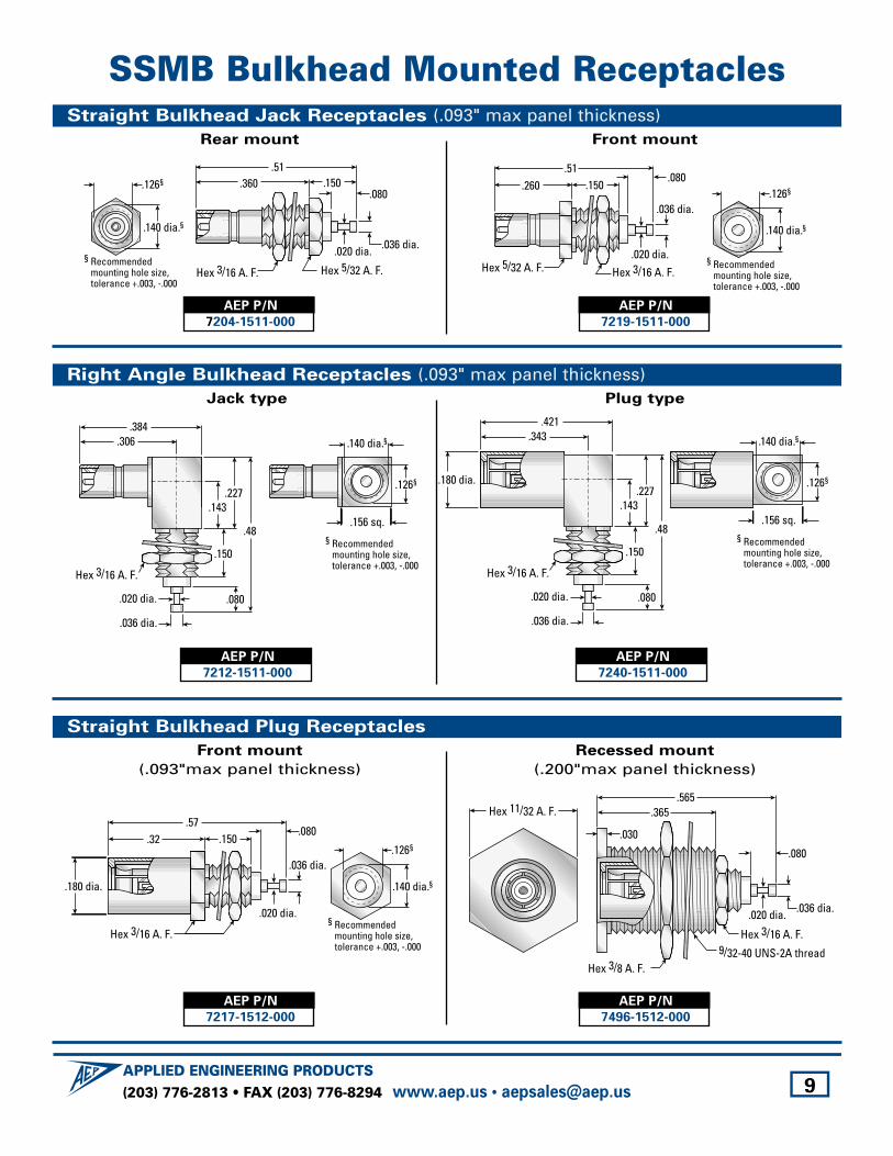
SSMB Bulkhead Mounted ReceptaclesStraight Bulkhead Jack Receptacles (.093" max panel thickness)
Rear mount Front mount
.260.51
.150.080
Hex 5/32 A. F. Hex 3/16 A. F.
.036 dia.
.020 dia.
.140 dia.§
.126§
§ Recommendedmounting hole size,tolerance +.003, -.000
.360.51
.150.080
Hex 5/32 A. F.Hex 3/16 A. F.
.036 dia..020 dia.
.140 dia.§
.126§
§ Recommendedmounting hole size,tolerance +.003, -.000
AEP P/N
7204-1511-000
AEP P/N
7219-1511-000
Straight Bulkhead Plug Receptacles
Front mount
(.093"max panel thickness)Recessed mount
(.200"max panel thickness)
.036 dia..020 dia.
Hex 3/8 A. F.
Hex 3/16 A. F.9/32-40 UNS-2A thread
Hex 11/32 A. F..565
.365
.080
.030.57
.32 .150.080
Hex 3/16 A. F.
.036 dia.
.020 dia.
.180 dia. .140 dia.§
.126§
§ Recommendedmounting hole size,tolerance +.003, -.000
AEP P/N
7217-1512-000
AEP P/N
7496-1512-000
Right Angle Bulkhead Receptacles (.093" max panel thickness)Jack type Plug type
.180 dia.
.421.343
.143
.080
Hex 3/16 A. F.
.036 dia.
.020 dia.
.227
.48
.150
.140 dia.§
.126§
.156 sq.
§ Recommendedmounting hole size,tolerance +.003, -.000
.384.306
.143
.080
Hex 3/16 A. F.
.036 dia.
.020 dia.
.227
.48
.150
.140 dia.§
.126§
.156 sq.
§ Recommendedmounting hole size,tolerance +.003, -.000
AEP P/N
7212-1511-000
AEP P/N
7240-1511-000
(203) 776-2813 • FAX (203) 776-8294APPLIED ENGINEERING PRODUCTS
www.aep.us • [email protected] 10
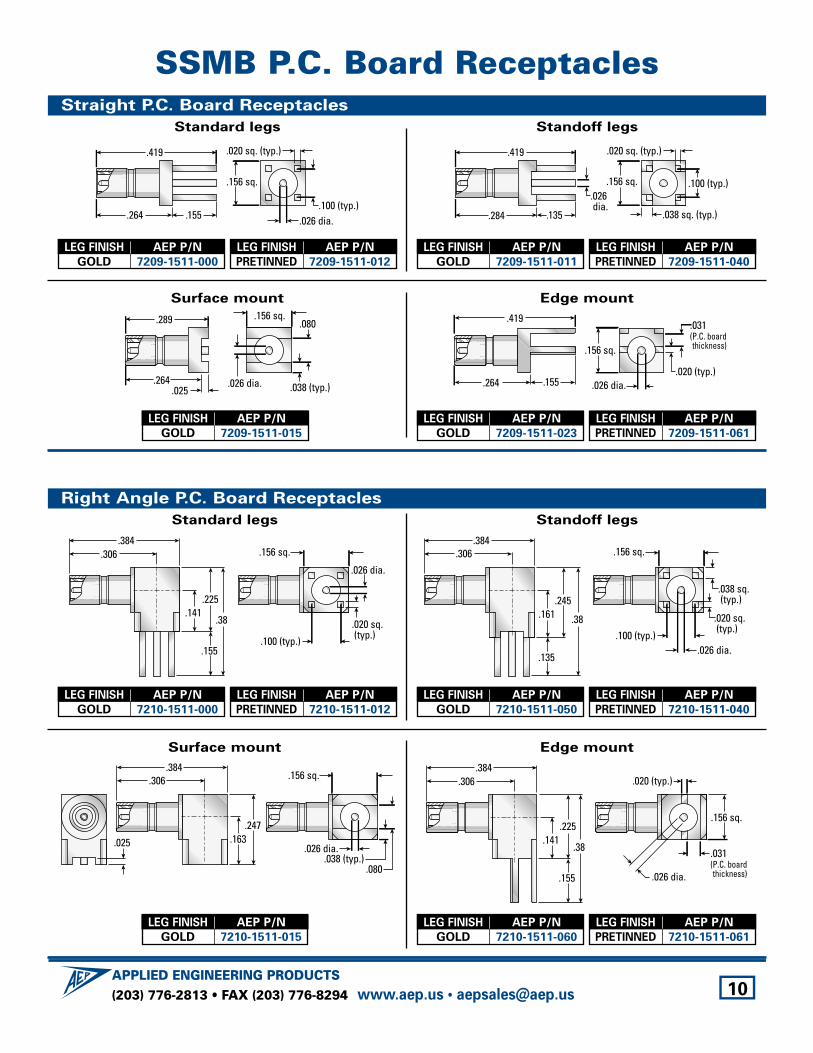
SSMB P.C. Board ReceptaclesStraight P.C. Board Receptacles
Standard legs Standoff legs
.135
.419
.284
.100 (typ.)
.020 sq. (typ.)
.038 sq. (typ.)
.156 sq..026 dia.
.155
.419
.264.100 (typ.)
.020 sq. (typ.)
.156 sq.
.026 dia.
Surface mount Edge mount
.155
.419
.264.020 (typ.)
.156 sq.
.026 dia.
.031(P.C. boardthickness)
.025
.289
.264.038 (typ.)
.080.156 sq.
.026 dia.
Right Angle P.C. Board Receptacles
Standard legs Standoff legs
.161.245
.38
.135
.100 (typ.)
.156 sq..384
.306
.038 sq. (typ.)
.020 sq. (typ.)
.026 dia.
.384.306
.141.225
.38
.155.100 (typ.)
.020 sq. (typ.)
.156 sq.
.026 dia.
LEG FINISH AEP P/N
GOLD 7209-1511-000
LEG FINISH AEP P/N
PRETINNED 7209-1511-012
LEG FINISH AEP P/N
GOLD 7209-1511-011
LEG FINISH AEP P/N
PRETINNED 7209-1511-040
LEG FINISH AEP P/N
GOLD 7209-1511-015
LEG FINISH AEP P/N
GOLD 7210-1511-000
LEG FINISH AEP P/N
PRETINNED 7210-1511-012
LEG FINISH AEP P/N
GOLD 7210-1511-050
LEG FINISH AEP P/N
PRETINNED 7210-1511-040
Surface mount Edge mount
.020 (typ.)
.156 sq.
.026 dia.
.031(P.C. boardthickness)
.384.306
.141.225
.38
.155
.163.247
.038 (typ.).080
.156 sq.
.026 dia..025
.384.306
LEG FINISH AEP P/N
GOLD 7210-1511-015
LEG FINISH AEP P/N
GOLD 7209-1511-023
LEG FINISH AEP P/N
PRETINNED 7209-1511-061
LEG FINISH AEP P/N
GOLD 7210-1511-060
LEG FINISH AEP P/N
PRETINNED 7210-1511-061
(203) 776-2813 • FAX (203) 776-8294APPLIED ENGINEERING PRODUCTS
www.aep.us • [email protected] 11
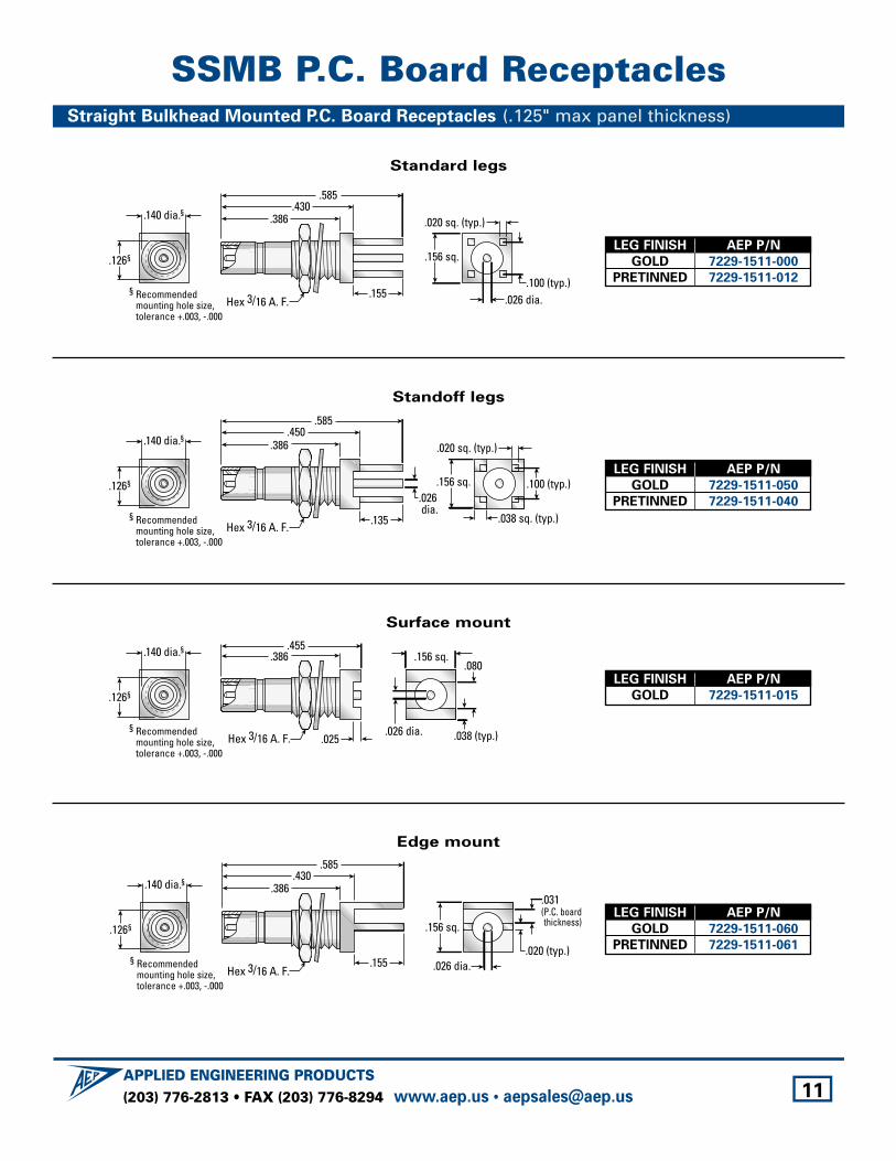
SSMB P.C. Board ReceptaclesStraight Bulkhead Mounted P.C. Board Receptacles (.125" max panel thickness)
Standard legs
Hex 3/16 A. F.
.140 dia.§
.126§
.155
.585.430
.386
§ Recommendedmounting hole size,tolerance +.003, -.000
.100 (typ.)
.020 sq. (typ.)
.156 sq.
.026 dia.
LEG FINISH AEP P/N
GOLD 7229-1511-000
PRETINNED 7229-1511-012
Standoff legs
Hex 3/16 A. F. .135
.585.450
.386.140 dia.§
.126§
§ Recommendedmounting hole size,tolerance +.003, -.000
.100 (typ.)
.020 sq. (typ.)
.038 sq. (typ.)
.156 sq..026 dia.
LEG FINISH AEP P/N
GOLD 7229-1511-050
PRETINNED 7229-1511-040
Surface mount
.455.386
Hex 3/16 A. F. .025
.140 dia.§
.126§
§ Recommendedmounting hole size,tolerance +.003, -.000
.038 (typ.)
.080.156 sq.
.026 dia.
LEG FINISH AEP P/N
GOLD 7229-1511-015
Edge mount
Hex 3/16 A. F.
.140 dia.§
.126§
.155
.585.430
.386
§ Recommendedmounting hole size,tolerance +.003, -.000
.020 (typ.)
.156 sq.
.026 dia.
.031(P.C. boardthickness)
LEG FINISH AEP P/N
GOLD 7229-1511-060
PRETINNED 7229-1511-061
(203) 776-2813 • FAX (203) 776-8294APPLIED ENGINEERING PRODUCTS
www.aep.us • [email protected] 12
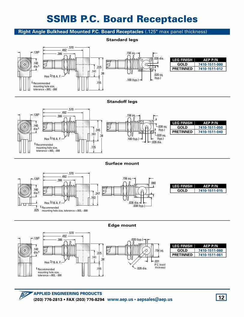
SSMB P.C. Board ReceptaclesRight Angle Bulkhead Mounted P.C. Board Receptacles (.125" max panel thickness)
Standard legs
.141.225
.38
.155.100 (typ.)
.020 sq. (typ.)
.156 sq.
.026 dia.
Hex 3/16 A. F.
.492.386
.570
§ Recommendedmounting hole size,tolerance +.003, -.000
.126§
.140 dia.§
Hex 3/16 A. F.
.492.386
.570
§ Recommendedmounting hole size,tolerance +.003, -.000
.126§
.161.245
.38
.135
.100 (typ.)
.156 sq.
.038 sq. (typ.)
.020 sq. (typ.)
.026 dia.
.140 dia.§
.025
Hex 3/16 A. F.
.492.386
.570
§ Recommendedmounting hole size, tolerance +.003, -.000
.140 dia.§
.126§
.163.247
.038 (typ.)
.080.156 sq.
.026 dia.
Hex 3/16 A. F.
.492.386
.570
§ Recommendedmounting hole size,tolerance +.003, -.000
.126§
.141.225
.38
.155
.140 dia.§
.020 (typ.)
.156 sq.
.026 dia.
.031(P.C. boardthickness)
LEG FINISH AEP P/N
GOLD 7410-1511-000
PRETINNED 7410-1511-012
Standoff legs
LEG FINISH AEP P/N
GOLD 7410-1511-050
PRETINNED 7410-1511-040
Surface mount
LEG FINISH AEP P/N
GOLD 7410-1511-015
Edge mount
LEG FINISH AEP P/N
GOLD 7410-1511-060
PRETINNED 7410-1511-061
(203) 776-2813 • FAX (203) 776-8294APPLIED ENGINEERING PRODUCTS
www.aep.us • [email protected] 13
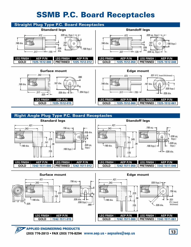
SSMB P.C. Board ReceptaclesStraight Plug Type P.C. Board Receptacles
Standard legs Standoff legs
.135
.472
.337
.180 dia. .100 (typ.)
.020 sq. (typ.)
.038 sq. (typ.)
.187 dia.
.026 dia.
.155
.472
.317
.187 dia.
.180 dia.
.100 (typ.)
.020 sq. (typ.)
.026 dia.
Surface mount Edge mount
.187 dia.
.026 dia.
.020 (typ.)
.031 (P.C. board thickness)
.155
.472
.317
.180 dia.
.342
.317
.187 dia.
.026 dia.
.180 dia.
.054 (typ.)
.080
.025
Right Angle Plug Type P.C. Board Receptacles
Standard legs Standoff legs
.100 (typ.)
.156 sq.
.038 sq. (typ.)
.020 sq. (typ.)
.026 dia.
.421.343
.161.245
.38
.135
.180 dia.
.421.343
.141.225
.38
.155
.180 dia..100 (typ.)
.020 sq. (typ.)
.156 sq.
.026 dia.
LEG FINISH AEP P/N
GOLD 7225-1512-000
LEG FINISH AEP P/N
PRETINNED 7225-1512-012
LEG FINISH AEP P/N
GOLD 7225-1512-050
LEG FINISH AEP P/N
PRETINNED 7225-1512-040
LEG FINISH AEP P/N
GOLD 7225-1512-015
LEG FINISH AEP P/N
GOLD 7242-1511-000
LEG FINISH AEP P/N
PRETINNED 7242-1511-012
LEG FINISH AEP P/N
GOLD 7242-1511-050
LEG FINISH AEP P/N
PRETINNED 7242-1511-040
Surface mount Edge mount
.020 (typ.)
.156 sq.
.026 dia.
.031(P.C. boardthickness)
.141.225
.38
.155
.421.343
.180 dia..025
.180 dia..163
.247
.038 (typ.).080
.156 sq.
.026 dia.
.421.343
LEG FINISH AEP P/N
GOLD 7242-1511-015
LEG FINISH AEP P/N
GOLD 7225-1512-060
LEG FINISH AEP P/N
PRETINNED 7225-1512-061
LEG FINISH AEP P/N
GOLD 7242-1511-060
LEG FINISH AEP P/N
PRETINNED 7242-1511-061
(203) 776-2813 • FAX (203) 776-8294APPLIED ENGINEERING PRODUCTS
www.aep.us • [email protected] 14
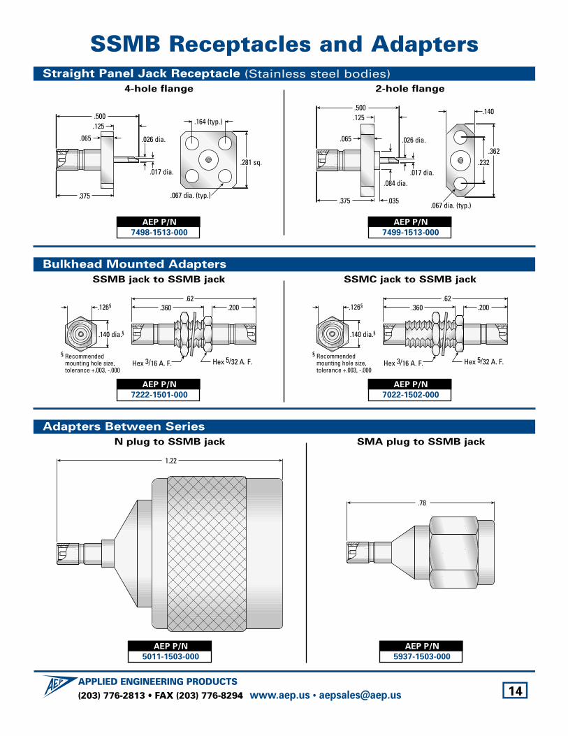
SSMB Receptacles and AdaptersStraight Panel Jack Receptacle (Stainless steel bodies)
4-hole flange 2-hole flange
.035
.140
.067 dia. (typ.)
.362.232
.500
.375
.065
.125
.026 dia.
.017 dia..084 dia.
.500
.375
.065
.125 .164 (typ.)
.067 dia. (typ.)
.281 sq.
.026 dia.
.017 dia.
AEP P/N
7498-1513-000
AEP P/N
7499-1513-000
Bulkhead Mounted Adapters
SSMB jack to SSMB jack SSMC jack to SSMB jack
.360.62
.200
Hex 5/32 A. F.
.140 dia.§
.126§
§ Recommendedmounting hole size,tolerance +.003, -.000
Hex 3/16 A. F.
.360.62
.200
Hex 5/32 A. F.Hex 3/16 A. F.
.140 dia.§
.126§
§ Recommendedmounting hole size,tolerance +.003, -.000
AEP P/N
7222-1501-000
AEP P/N
7022-1502-000
Adapters Between Series
N plug to SSMB jack SMA plug to SSMB jack
.78
1.22
AEP P/N
5011-1503-000
AEP P/N
5937-1503-000
(203) 776-2813 • FAX (203) 776-8294APPLIED ENGINEERING PRODUCTS
www.aep.us • [email protected] 15
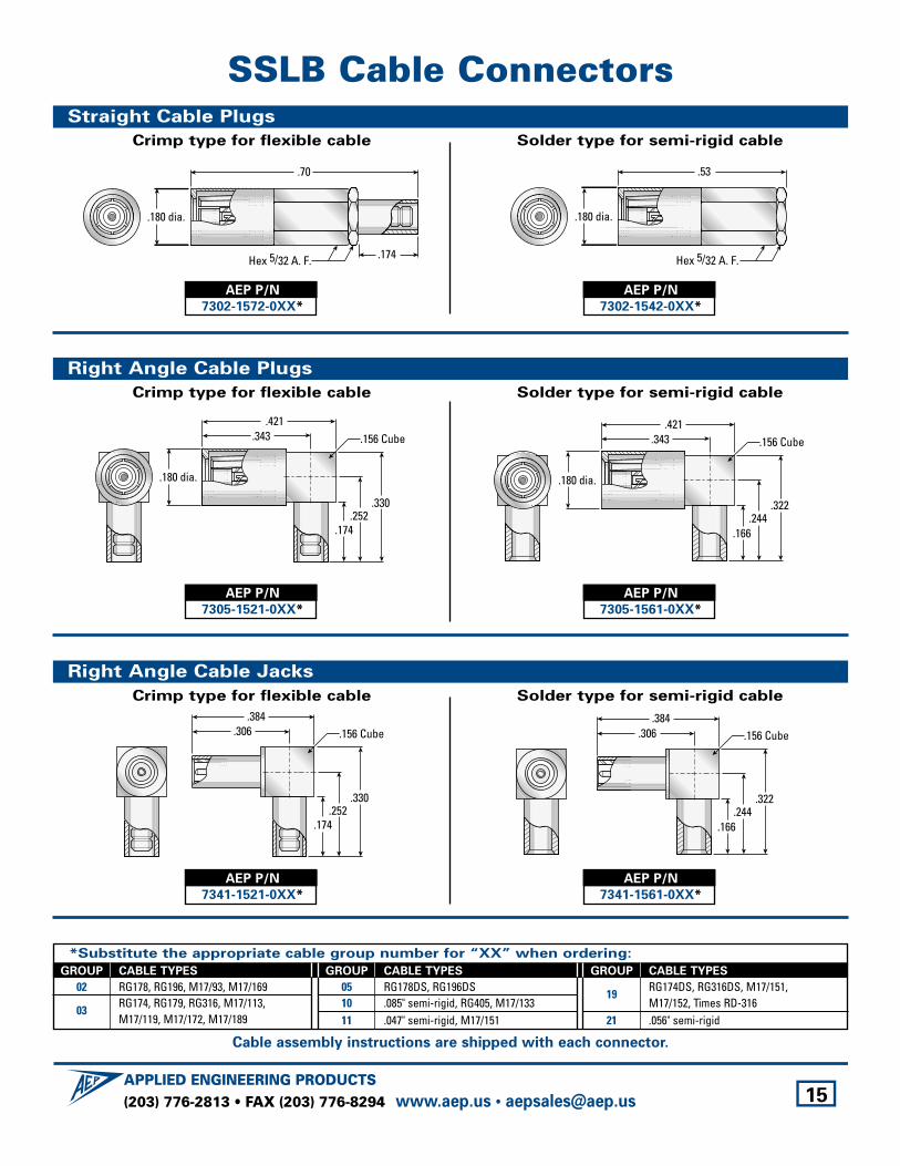
SSLB Cable ConnectorsStraight Cable Plugs
Crimp type for flexible cable Solder type for semi-rigid cable
.53
Hex 5/32 A. F.
.180 dia.
.174
.70
Hex 5/32 A. F.
.180 dia.
AEP P/N
7302-1572-0XX*
AEP P/N
7302-1542-0XX*
Right Angle Cable Plugs
Crimp type for flexible cable Solder type for semi-rigid cable
.166.244
.322
.421.343
.180 dia.
.156 Cube
.421.343
.174.252
.330
.180 dia.
.156 Cube
AEP P/N
7305-1521-0XX*
AEP P/N
7305-1561-0XX*
Right Angle Cable Jacks
Crimp type for flexible cable Solder type for semi-rigid cable
.166.244
.322
.156 Cube.384
.306.384
.306
.174.252
.330
.156 Cube
AEP P/N
7341-1521-0XX*
AEP P/N
7341-1561-0XX*
*Substitute the appropriate cable group number for “XX” when ordering:
GROUP CABLE TYPES
02 RG178, RG196, M17/93, M17/169
03RG174, RG179, RG316, M17/113, M17/119, M17/172, M17/189
GROUP CABLE TYPES
05 RG178DS, RG196DS10 .085" semi-rigid, RG405, M17/13311 .047" semi-rigid, M17/151
GROUP CABLE TYPES
19RG174DS, RG316DS, M17/151,M17/152, Times RD-316
21 .056" semi-rigid
Cable assembly instructions are shipped with each connector.
(203) 776-2813 • FAX (203) 776-8294APPLIED ENGINEERING PRODUCTS
www.aep.us • [email protected] 16
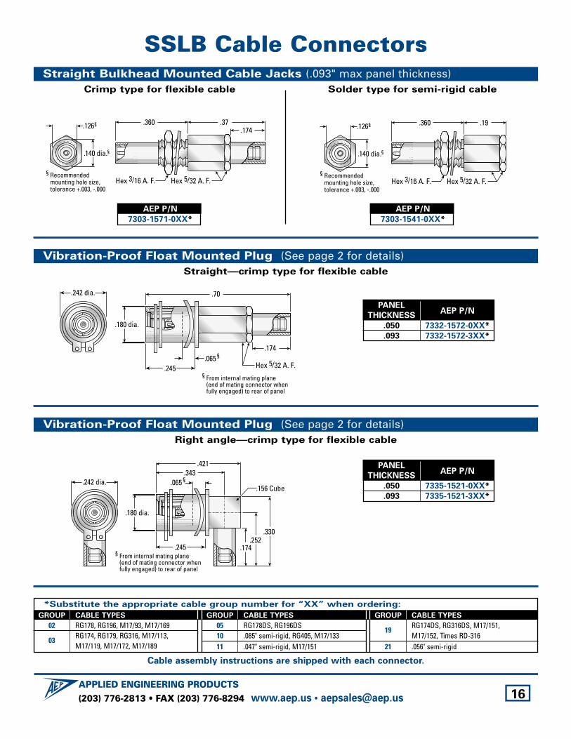
SSLB Cable ConnectorsStraight Bulkhead Mounted Cable Jacks (.093" max panel thickness)
Crimp type for flexible cable Solder type for semi-rigid cable
.360 .19
Hex 5/32 A. F.Hex 3/16 A. F.
.140 dia.§
.126§
§ Recommendedmounting hole size,tolerance +.003, -.000
.140 dia.§
.126§
§ Recommendedmounting hole size,tolerance +.003, -.000
.174.360 .37
Hex 5/32 A. F.Hex 3/16 A. F.
AEP P/N
7303-1571-0XX*
AEP P/N
7303-1541-0XX*
Vibration-Proof Float Mounted Plug (See page 2 for details)Straight—crimp type for flexible cable
.70
.174
Hex 5/32 A. F.§ From internal mating plane
(end of mating connector whenfully engaged) to rear of panel
§ .065
.180 dia.
.245
.242 dia.
Vibration-Proof Float Mounted Plug (See page 2 for details)Right angle—crimp type for flexible cable
.421.343
§ From internal mating plane(end of mating connector whenfully engaged) to rear of panel
§ .065
.180 dia.
.245 .174.252
.330
.156 Cube.242 dia.
PANELAEP P/N
THICKNESS
.050 7332-1572-0XX*
.093 7332-1572-3XX*
PANELAEP P/N
THICKNESS
.050 7335-1521-0XX*
.093 7335-1521-3XX*
*Substitute the appropriate cable group number for “XX” when ordering:
GROUP CABLE TYPES
02 RG178, RG196, M17/93, M17/169
03RG174, RG179, RG316, M17/113, M17/119, M17/172, M17/189
GROUP CABLE TYPES
05 RG178DS, RG196DS10 .085" semi-rigid, RG405, M17/13311 .047" semi-rigid, M17/151
GROUP CABLE TYPES
19RG174DS, RG316DS, M17/151,M17/152, Times RD-316
21 .056" semi-rigid
Cable assembly instructions are shipped with each connector.
(203) 776-2813 • FAX (203) 776-8294APPLIED ENGINEERING PRODUCTS
www.aep.us • [email protected] 17
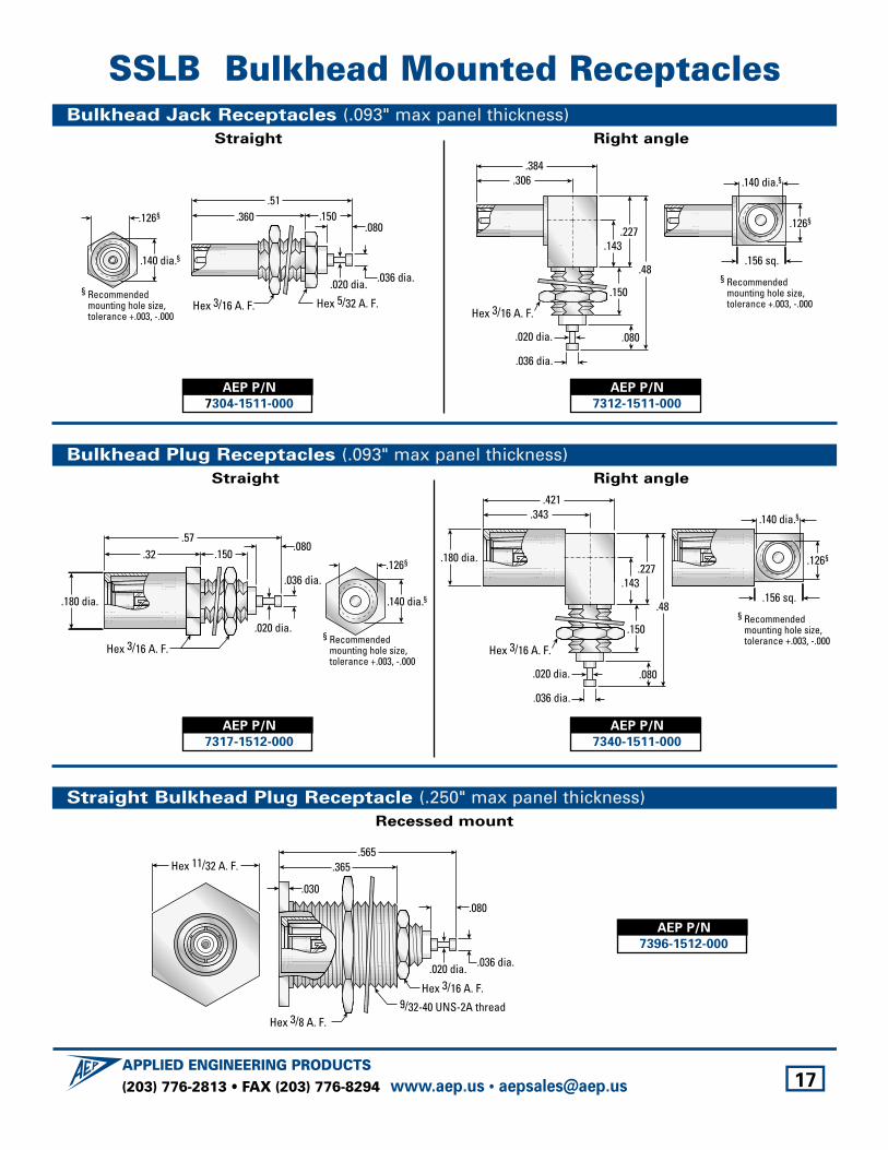
SSLB Bulkhead Mounted ReceptaclesBulkhead Jack Receptacles (.093" max panel thickness)
Straight Right angle
.384.306
.143
.080
Hex 3/16 A. F.
.036 dia.
.020 dia.
.227
.48
.150
.140 dia.§
.126§
.156 sq.
§ Recommendedmounting hole size,tolerance +.003, -.000
.360.51
.150.080
Hex 5/32 A. F.Hex 3/16 A. F.
.036 dia..020 dia.
.140 dia.§
.126§
§ Recommendedmounting hole size,tolerance +.003, -.000
AEP P/N
7304-1511-000
AEP P/N
7312-1511-000
Straight Bulkhead Plug Receptacle (.250" max panel thickness)Recessed mount
.036 dia..020 dia.
Hex 3/8 A. F.
Hex 3/16 A. F.9/32-40 UNS-2A thread
Hex 11/32 A. F..565
.365
.080
.030
AEP P/N
7396-1512-000
Bulkhead Plug Receptacles (.093" max panel thickness)Straight Right angle
.180 dia.
.421.343
.143
.080
Hex 3/16 A. F.
.036 dia.
.020 dia.
.227
.48
.150
.140 dia.§
.126§
.156 sq.
§ Recommendedmounting hole size,tolerance +.003, -.000
.57.32 .150
.080
Hex 3/16 A. F.
.036 dia.
.020 dia.
.180 dia. .140 dia.§
.126§
§ Recommendedmounting hole size,tolerance +.003, -.000
AEP P/N
7317-1512-000
AEP P/N
7340-1511-000
(203) 776-2813 • FAX (203) 776-8294APPLIED ENGINEERING PRODUCTS
www.aep.us • [email protected] 18
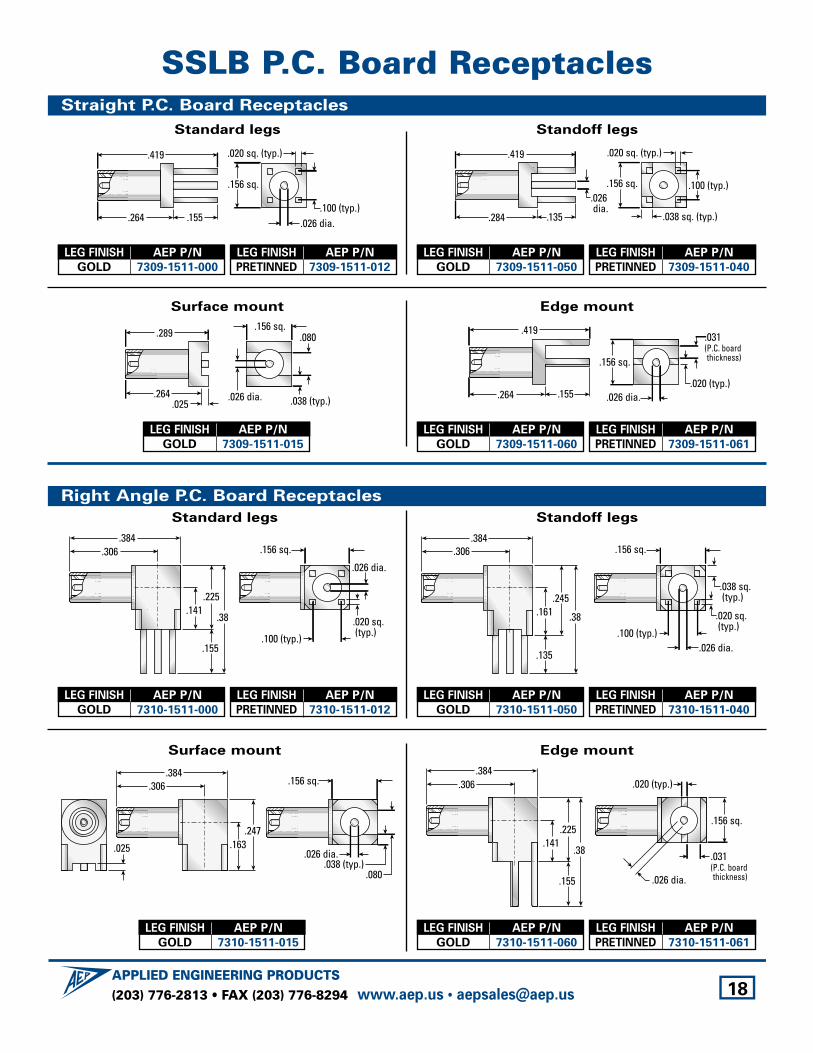
SSLB P.C. Board ReceptaclesStraight P.C. Board Receptacles
Standard legs Standoff legs
.135
.419
.284
.100 (typ.)
.020 sq. (typ.)
.038 sq. (typ.)
.156 sq..026 dia.
.155
.419
.264.100 (typ.)
.020 sq. (typ.)
.156 sq.
.026 dia.
Surface mount Edge mount
.155
.419
.264.020 (typ.)
.156 sq.
.026 dia.
.031(P.C. boardthickness)
.025
.289
.264.038 (typ.)
.080.156 sq.
.026 dia.
Right Angle P.C. Board Receptacles
Standard legs Standoff legs
.161.245
.38
.135
.384.306
.100 (typ.)
.156 sq.
.038 sq. (typ.)
.020 sq. (typ.)
.026 dia.
.384.306
.141.225
.38
.155.100 (typ.)
.020 sq. (typ.)
.156 sq.
.026 dia.
LEG FINISH AEP P/N
GOLD 7309-1511-000
LEG FINISH AEP P/N
PRETINNED 7309-1511-012
LEG FINISH AEP P/N
GOLD 7309-1511-050
LEG FINISH AEP P/N
PRETINNED 7309-1511-040
LEG FINISH AEP P/N
GOLD 7309-1511-015
LEG FINISH AEP P/N
GOLD 7310-1511-000
LEG FINISH AEP P/N
PRETINNED 7310-1511-012
LEG FINISH AEP P/N
GOLD 7310-1511-050
LEG FINISH AEP P/N
PRETINNED 7310-1511-040
Surface mount Edge mount
.384.306
.141.225
.38
.155
.020 (typ.)
.156 sq.
.026 dia.
.031(P.C. boardthickness)
.163.247
.038 (typ.).080
.156 sq.
.026 dia..025
.384.306
LEG FINISH AEP P/N
GOLD 7310-1511-015
LEG FINISH AEP P/N
GOLD 7310-1511-060
LEG FINISH AEP P/N
PRETINNED 7310-1511-061
LEG FINISH AEP P/N
GOLD 7309-1511-060
LEG FINISH AEP P/N
PRETINNED 7309-1511-061
(203) 776-2813 • FAX (203) 776-8294APPLIED ENGINEERING PRODUCTS
www.aep.us • [email protected] 19
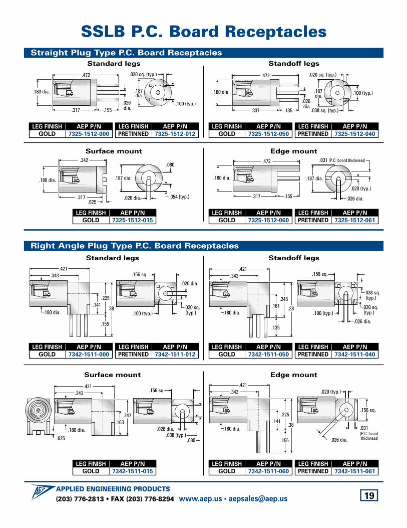
SSLB P.C. Board ReceptaclesStraight Plug Type P.C. Board Receptacles
Standard legs Standoff legs
.135
.472
.337
.180 dia. .100 (typ.)
.020 sq. (typ.)
.038 sq. (typ.)
.187 dia.
.026 dia.
.155
.472
.317
.180 dia. .187 dia.
.100 (typ.)
.020 sq. (typ.)
.026 dia.
Surface mount Edge mount
.187 dia.
.026 dia.
.020 (typ.)
.031 (P.C. board thickness)
.155
.472
.317
.180 dia.
.342
.317
.187 dia.
.026 dia.
.180 dia.
.054 (typ.)
.080
.025
Right Angle Plug Type P.C. Board Receptacles
Standard legs Standoff legs
.100 (typ.)
.156 sq.
.038 sq. (typ.)
.020 sq. (typ.)
.026 dia.
.421.343
.161.245
.38
.135
.180 dia.
.421.343
.141.225
.38
.155
.100 (typ.).020 sq. (typ.)
.156 sq.
.026 dia.
.180 dia.
LEG FINISH AEP P/N
GOLD 7325-1512-000
LEG FINISH AEP P/N
PRETINNED 7325-1512-012
LEG FINISH AEP P/N
GOLD 7325-1512-050
LEG FINISH AEP P/N
PRETINNED 7325-1512-040
LEG FINISH AEP P/N
GOLD 7325-1512-015
LEG FINISH AEP P/N
GOLD 7342-1511-000
LEG FINISH AEP P/N
PRETINNED 7342-1511-012
LEG FINISH AEP P/N
GOLD 7342-1511-050
LEG FINISH AEP P/N
PRETINNED 7342-1511-040
Surface mount Edge mount
.020 (typ.)
.156 sq.
.026 dia.
.031(P.C. boardthickness)
.141.225
.38
.155
.421.343
.180 dia.
.025
.163.247
.421.343
.180 dia..038 (typ.)
.080
.156 sq.
.026 dia.
LEG FINISH AEP P/N
GOLD 7342-1511-015
LEG FINISH AEP P/N
GOLD 7325-1512-060
LEG FINISH AEP P/N
PRETINNED 7325-1512-061
LEG FINISH AEP P/N
GOLD 7342-1511-060
LEG FINISH AEP P/N
PRETINNED 7342-1511-061
(203) 776-2813 • FAX (203) 776-8294APPLIED ENGINEERING PRODUCTS
www.aep.us • [email protected] 20
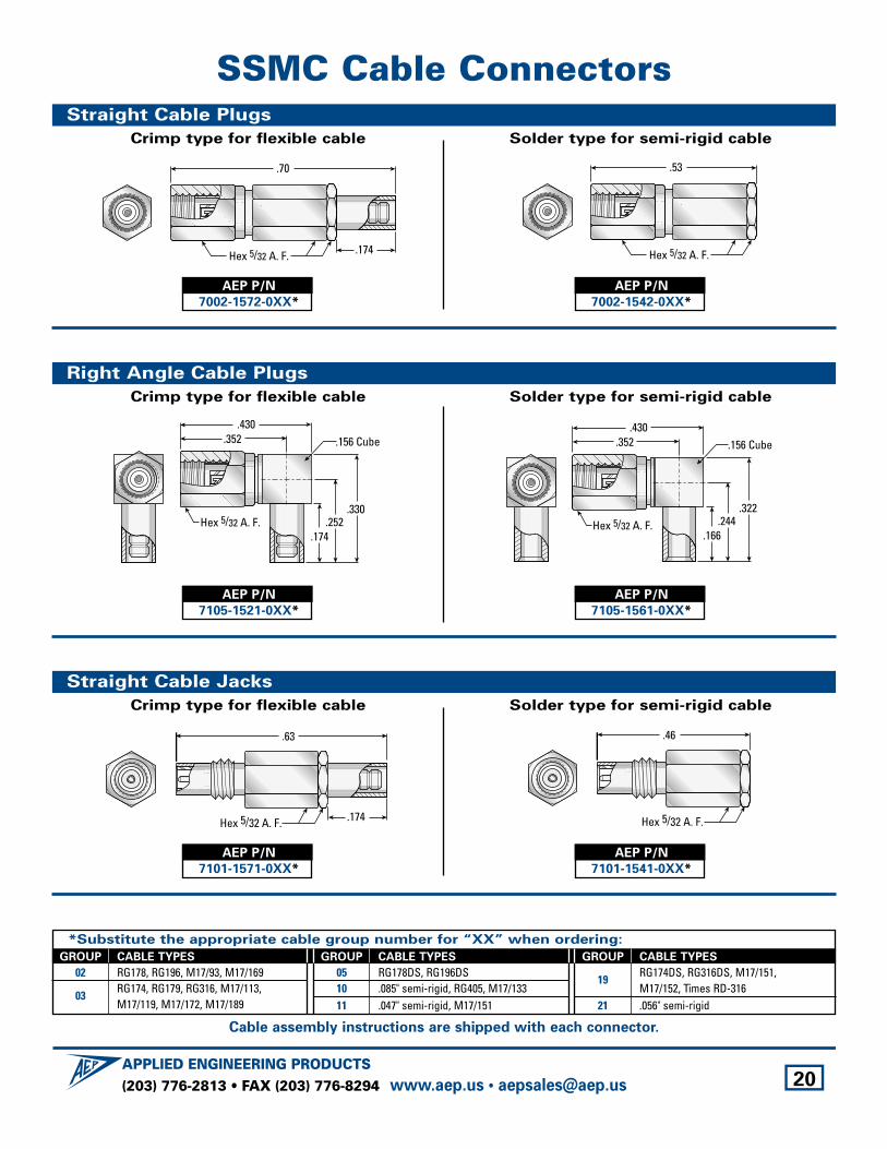
SSMC Cable ConnectorsStraight Cable Plugs
Crimp type for flexible cable Solder type for semi-rigid cable
.53
Hex 5/32 A. F..174
.70
Hex 5/32 A. F.
AEP P/N
7002-1572-0XX*
AEP P/N
7002-1542-0XX*
Straight Cable Jacks
Crimp type for flexible cable Solder type for semi-rigid cable
.46
Hex 5/32 A. F..174
.63
Hex 5/32 A. F.
AEP P/N
7101-1571-0XX*
AEP P/N
7101-1541-0XX*
Right Angle Cable Plugs
Crimp type for flexible cable Solder type for semi-rigid cable
.430.352
.166.244
.322
.156 Cube
Hex 5/32 A. F.
.430.352
.174.252
.330
.156 Cube
Hex 5/32 A. F.
AEP P/N
7105-1521-0XX*
AEP P/N
7105-1561-0XX*
*Substitute the appropriate cable group number for “XX” when ordering:
GROUP CABLE TYPES
02 RG178, RG196, M17/93, M17/169
03RG174, RG179, RG316, M17/113, M17/119, M17/172, M17/189
GROUP CABLE TYPES
05 RG178DS, RG196DS10 .085" semi-rigid, RG405, M17/13311 .047" semi-rigid, M17/151
GROUP CABLE TYPES
19RG174DS, RG316DS, M17/151,M17/152, Times RD-316
21 .056" semi-rigid
Cable assembly instructions are shipped with each connector.
(203) 776-2813 • FAX (203) 776-8294APPLIED ENGINEERING PRODUCTS
www.aep.us • [email protected] 21
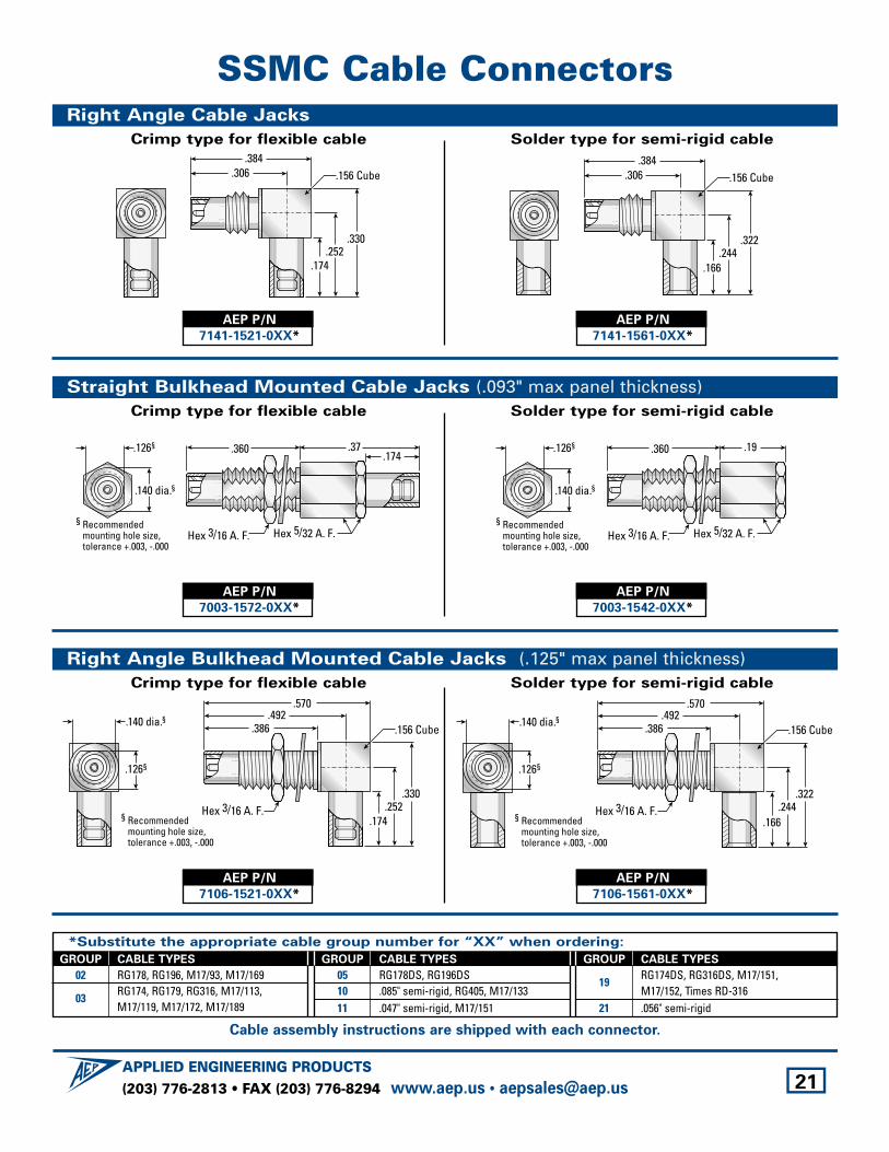
SSMC Cable ConnectorsRight Angle Cable Jacks
Crimp type for flexible cable Solder type for semi-rigid cable
.166.244
.322
.384.306 .156 Cube
.384.306
.174.252
.330
.156 Cube
AEP P/N
7141-1521-0XX*
AEP P/N
7141-1561-0XX*
Straight Bulkhead Mounted Cable Jacks (.093" max panel thickness)Crimp type for flexible cable Solder type for semi-rigid cable
.19
Hex 5/32 A. F.
.360
.140 dia.§
.126§
§ Recommendedmounting hole size,tolerance +.003, -.000
Hex 3/16 A. F.
.174.37
Hex 5/32 A. F.
.360
.140 dia.§
.126§
§ Recommendedmounting hole size,tolerance +.003, -.000
Hex 3/16 A. F.
AEP P/N
7003-1572-0XX*
AEP P/N
7003-1542-0XX*
Right Angle Bulkhead Mounted Cable Jacks (.125" max panel thickness)Crimp type for flexible cable Solder type for semi-rigid cable
Hex 3/16 A. F.
.492.386
.570
.166.244
.322
.156 Cube
§ Recommendedmounting hole size,tolerance +.003, -.000
.140 dia.§
.126§
Hex 3/16 A. F.
.492.386
.570
.174.252
.330
.156 Cube
§ Recommendedmounting hole size,tolerance +.003, -.000
.140 dia.§
.126§
AEP P/N
7106-1521-0XX*
AEP P/N
7106-1561-0XX*
*Substitute the appropriate cable group number for “XX” when ordering:
GROUP CABLE TYPES
02 RG178, RG196, M17/93, M17/169
03RG174, RG179, RG316, M17/113, M17/119, M17/172, M17/189
GROUP CABLE TYPES
05 RG178DS, RG196DS10 .085" semi-rigid, RG405, M17/13311 .047" semi-rigid, M17/151
GROUP CABLE TYPES
19RG174DS, RG316DS, M17/151,M17/152, Times RD-316
21 .056" semi-rigid
Cable assembly instructions are shipped with each connector.
(203) 776-2813 • FAX (203) 776-8294APPLIED ENGINEERING PRODUCTS
www.aep.us • [email protected] 22
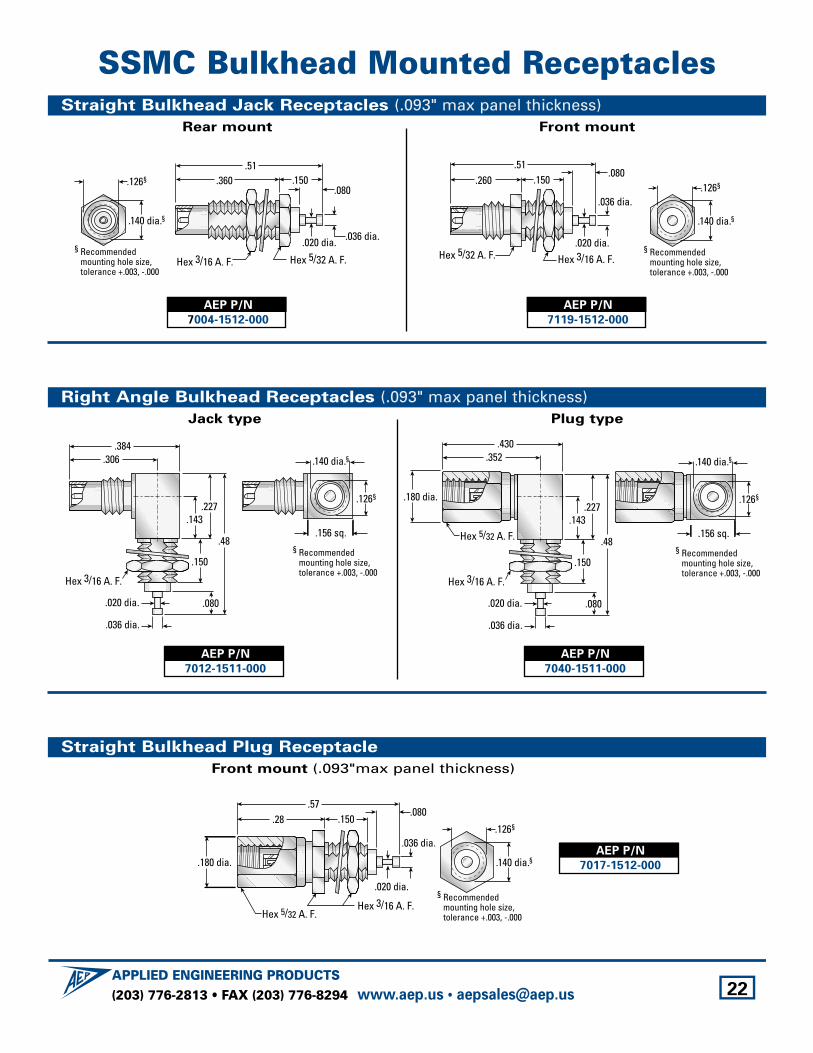
SSMC Bulkhead Mounted ReceptaclesStraight Bulkhead Jack Receptacles (.093" max panel thickness)
Rear mount Front mount
.260.51
.150.080
Hex 5/32 A. F. Hex 3/16 A. F.
.036 dia.
.020 dia.
.140 dia.§
.126§
§ Recommendedmounting hole size,tolerance +.003, -.000
.360.51
.150.080
Hex 5/32 A. F.Hex 3/16 A. F.
.036 dia..020 dia.
.140 dia.§
.126§
§ Recommendedmounting hole size,tolerance +.003, -.000
AEP P/N
7004-1512-000
AEP P/N
7119-1512-000
Straight Bulkhead Plug Receptacle
Front mount (.093"max panel thickness)
.57.28 .150
.080
Hex 3/16 A. F.
.036 dia.
.020 dia.
.180 dia. .140 dia.§
.126§
§ Recommendedmounting hole size,tolerance +.003, -.000Hex 5/32 A. F.
AEP P/N
7017-1512-000
Right Angle Bulkhead Receptacles (.093" max panel thickness)Jack type Plug type
.180 dia.
.430.352
.143
.080
Hex 3/16 A. F.
.036 dia.
.020 dia.
.227
.48
.150
.140 dia.§
.126§
.156 sq.
§ Recommendedmounting hole size,tolerance +.003, -.000
Hex 5/32 A. F.
.384.306
.143
.080
Hex 3/16 A. F.
.036 dia.
.020 dia.
.227
.48
.150
.140 dia.§
.126§
.156 sq.
§ Recommendedmounting hole size,tolerance +.003, -.000
AEP P/N
7012-1511-000
AEP P/N
7040-1511-000
(203) 776-2813 • FAX (203) 776-8294APPLIED ENGINEERING PRODUCTS
www.aep.us • [email protected] 23
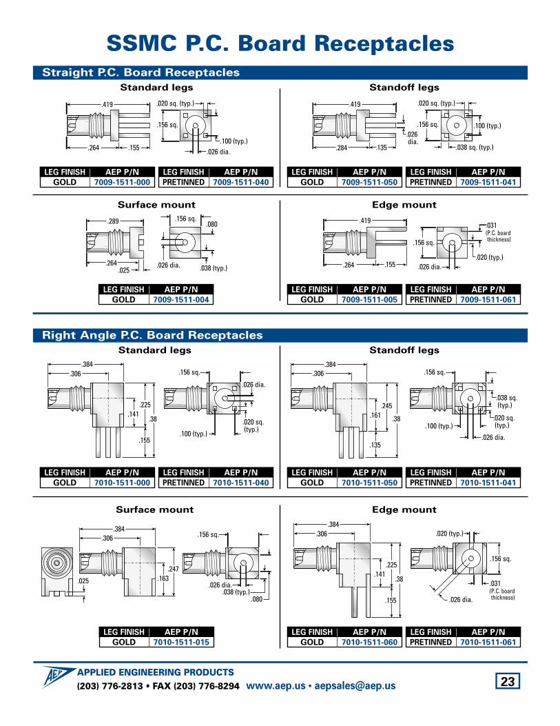
SSMC P.C. Board ReceptaclesStraight P.C. Board Receptacles
Standard legs Standoff legs
.135
.419
.284
.100 (typ.)
.020 sq. (typ.)
.038 sq. (typ.)
.156 sq..026 dia.
.155
.419
.264.100 (typ.)
.020 sq. (typ.)
.156 sq.
.026 dia.
Surface mount Edge mount
.155
.419
.264.020 (typ.)
.156 sq.
.026 dia.
.031(P.C. boardthickness)
.025
.289
.264.038 (typ.)
.080.156 sq.
.026 dia.
Right Angle P.C. Board Receptacles
Standard legs Standoff legs
.161.245
.38
.135
.100 (typ.)
.156 sq..384
.306
.038 sq. (typ.)
.020 sq. (typ.)
.026 dia.
.384.306
.141.225
.38
.155.100 (typ.)
.020 sq. (typ.)
.156 sq.
.026 dia.
LEG FINISH AEP P/N
GOLD 7009-1511-000
LEG FINISH AEP P/N
PRETINNED 7009-1511-040
LEG FINISH AEP P/N
GOLD 7009-1511-050
LEG FINISH AEP P/N
PRETINNED 7009-1511-041
LEG FINISH AEP P/N
GOLD 7009-1511-004
LEG FINISH AEP P/N
GOLD 7010-1511-000
LEG FINISH AEP P/N
PRETINNED 7010-1511-040
LEG FINISH AEP P/N
GOLD 7010-1511-050
LEG FINISH AEP P/N
PRETINNED 7010-1511-041
Surface mount Edge mount
.384.306
.141.225
.38
.155
.020 (typ.)
.156 sq.
.026 dia.
.031(P.C. boardthickness)
.163.247
.038 (typ.).080
.156 sq.
.026 dia..025
.384.306
LEG FINISH AEP P/N
GOLD 7010-1511-015
LEG FINISH AEP P/N
GOLD 7009-1511-005
LEG FINISH AEP P/N
PRETINNED 7009-1511-061
LEG FINISH AEP P/N
GOLD 7010-1511-060
LEG FINISH AEP P/N
PRETINNED 7010-1511-061
(203) 776-2813 • FAX (203) 776-8294APPLIED ENGINEERING PRODUCTS
www.aep.us • [email protected] 24
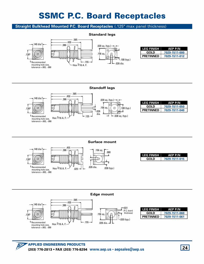
SSMC P.C. Board ReceptaclesStraight Bulkhead Mounted P.C. Board Receptacles (.125" max panel thickness)
Standard legs
Hex 3/16 A. F.
.140 dia.§
.126§
.155
.585.430
.386
§ Recommendedmounting hole size,tolerance +.003, -.000
.100 (typ.)
.020 sq. (typ.)
.156 sq.
.026 dia.
LEG FINISH AEP P/N
GOLD 7029-1511-000
PRETINNED 7029-1511-012
Standoff legs
Hex 3/16 A. F. .135
.585.450
.386.140 dia.§
.126§
§ Recommendedmounting hole size,tolerance +.003, -.000
.100 (typ.)
.020 sq. (typ.)
.038 sq. (typ.)
.156 sq..026 dia.
LEG FINISH AEP P/N
GOLD 7029-1511-050
PRETINNED 7029-1511-040
Surface mount
.455.386
Hex 3/16 A. F. .025
.140 dia.§
.126§
§ Recommendedmounting hole size,tolerance +.003, -.000
.038 (typ.)
.080.156 sq.
.026 dia.
LEG FINISH AEP P/N
GOLD 7029-1511-015
Edge mount
Hex 3/16 A. F.
.140 dia.§
.126§
.155
.585.430
.386
§ Recommendedmounting hole size,tolerance +.003, -.000
.020 (typ.)
.156 sq.
.026 dia.
.031(P.C. boardthickness)
LEG FINISH AEP P/N
GOLD 7029-1511-060
PRETINNED 7029-1511-061
(203) 776-2813 • FAX (203) 776-8294APPLIED ENGINEERING PRODUCTS
www.aep.us • [email protected] 25
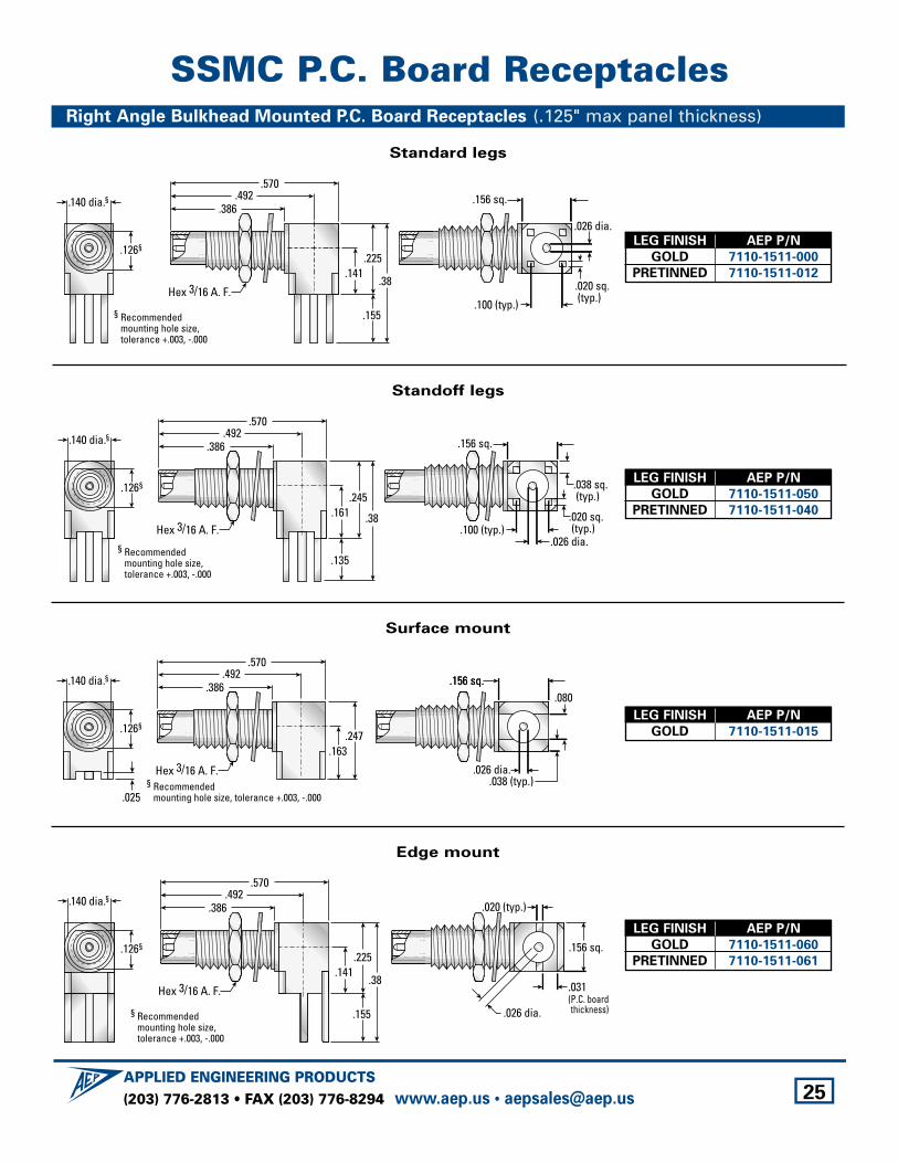
SSMC P.C. Board ReceptaclesRight Angle Bulkhead Mounted P.C. Board Receptacles (.125" max panel thickness)
Standard legs
Hex 3/16 A. F.
.492.386
.570
.141.225
.38
.155§ Recommendedmounting hole size,tolerance +.003, -.000
.100 (typ.)
.020 sq. (typ.)
.156 sq.
.026 dia.
.140 dia.§
.126§
§ Recommendedmounting hole size,tolerance +.003, -.000
.161.245
.38
.135
.100 (typ.)
.156 sq.
.038 sq. (typ.)
.020 sq. (typ.)
.026 dia.Hex 3/16 A. F.
.492.386
.570
.140 dia.§
.126§
§ Recommendedmounting hole size, tolerance +.003, -.000
.163.247
.156 sq.
.025.038 (typ.)
.080.156 sq.
.026 dia.Hex 3/16 A. F.
.492.386
.570
.140 dia.§
.126§
§ Recommendedmounting hole size,tolerance +.003, -.000
.141.225
.38
.155
.020 (typ.)
.156 sq.
.026 dia.
.031(P.C. boardthickness)
Hex 3/16 A. F.
.492.386
.570
.140 dia.§
.126§
LEG FINISH AEP P/N
GOLD 7110-1511-000
PRETINNED 7110-1511-012
Standoff legs
LEG FINISH AEP P/N
GOLD 7110-1511-050
PRETINNED 7110-1511-040
Surface mount
LEG FINISH AEP P/N
GOLD 7110-1511-015
Edge mount
LEG FINISH AEP P/N
GOLD 7110-1511-060
PRETINNED 7110-1511-061
(203) 776-2813 • FAX (203) 776-8294APPLIED ENGINEERING PRODUCTS
www.aep.us • [email protected] 26
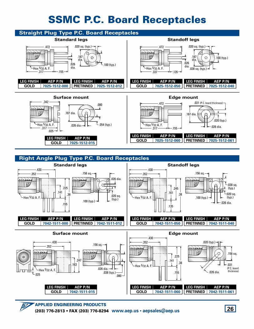
SSMC P.C. Board ReceptaclesStraight Plug Type P.C. Board Receptacles
Standard legs Standoff legs
.135
.472
.337
.100 (typ.)
.020 sq. (typ.)
.038 sq. (typ.)
.187 dia.
.026 dia.
Hex 5/32 A. F..155
.472
.317
.187 dia.
.100 (typ.)
.020 sq. (typ.)
.026 dia.Hex 5/32 A. F.
Surface mount Edge mount
.187 dia.
.026 dia.
.020 (typ.)
.031 (P.C. board thickness)
.155
.472
.317Hex 5/32 A. F.
.342
.317
.187 dia.
.026 dia. .054 (typ.)
.080
.025
Hex 5/32 A. F.
Right Angle Plug Type P.C. Board Receptacles
Standard legs Standoff legs
.100 (typ.)
.156 sq.
.038 sq. (typ.)
.020 sq. (typ.)
.026 dia.
.161.245
.38
.135
.430.352
Hex 5/32 A. F.
.141.225
.38
.155
.430.352
.100 (typ.)
.020 sq. (typ.)
.156 sq.
.026 dia.
Hex 5/32 A. F.
LEG FINISH AEP P/N
GOLD 7025-1512-000
LEG FINISH AEP P/N
PRETINNED 7025-1512-012
LEG FINISH AEP P/N
GOLD 7025-1512-050
LEG FINISH AEP P/N
PRETINNED 7025-1512-040
LEG FINISH AEP P/N
GOLD 7025-1512-015
LEG FINISH AEP P/N
GOLD 7042-1511-000
LEG FINISH AEP P/N
PRETINNED 7042-1511-012
LEG FINISH AEP P/N
GOLD 7042-1511-050
LEG FINISH AEP P/N
PRETINNED 7042-1511-040
Surface mount Edge mount
.141.225
.38
.155
.430.352 .020 (typ.)
.156 sq.
.026 dia.
.031(P.C. boardthickness)
Hex 5/32 A. F..163.247
.430.352
.025 .038 (typ.).080
.156 sq.
.026 dia.Hex 5/32 A. F.
LEG FINISH AEP P/N
GOLD 7042-1511-015
LEG FINISH AEP P/N
GOLD 7025-1512-060
LEG FINISH AEP P/N
PRETINNED 7025-1512-061
LEG FINISH AEP P/N
GOLD 7042-1511-060
LEG FINISH AEP P/N
PRETINNED 7042-1511-061
(203) 776-2813 • FAX (203) 776-8294APPLIED ENGINEERING PRODUCTS
www.aep.us • [email protected] 27
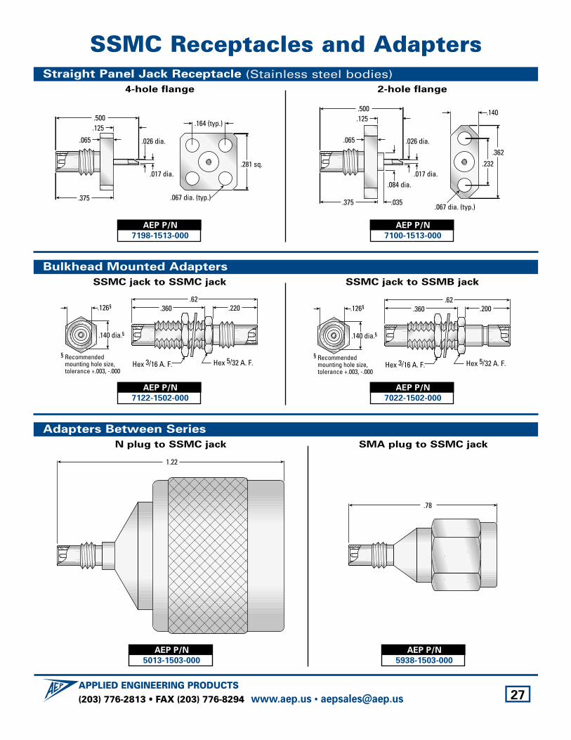
SSMC Receptacles and AdaptersStraight Panel Jack Receptacle (Stainless steel bodies)
4-hole flange 2-hole flange
.084 dia.
.035
.140
.067 dia. (typ.)
.362.232
.500
.375
.065
.125
.026 dia.
.017 dia.
.500
.375
.065
.125 .164 (typ.)
.067 dia. (typ.)
.281 sq.
.026 dia.
.017 dia.
AEP P/N
7198-1513-000
AEP P/N
7100-1513-000
Bulkhead Mounted Adapters
SSMC jack to SSMC jack SSMC jack to SSMB jack
.360.62
.200
Hex 5/32 A. F.
.140 dia.§
.126§
§ Recommendedmounting hole size,tolerance +.003, -.000
Hex 3/16 A. F.
.360.62
.220
Hex 5/32 A. F.
.140 dia.§
.126§
§ Recommendedmounting hole size,tolerance +.003, -.000
Hex 3/16 A. F.
AEP P/N
7122-1502-000
AEP P/N
7022-1502-000
Adapters Between Series
N plug to SSMC jack SMA plug to SSMC jack
.78
1.22
AEP P/N
5013-1503-000
AEP P/N
5938-1503-000
(203) 776-2813 • FAX (203) 776-8294APPLIED ENGINEERING PRODUCTS
www.aep.us • [email protected] 28
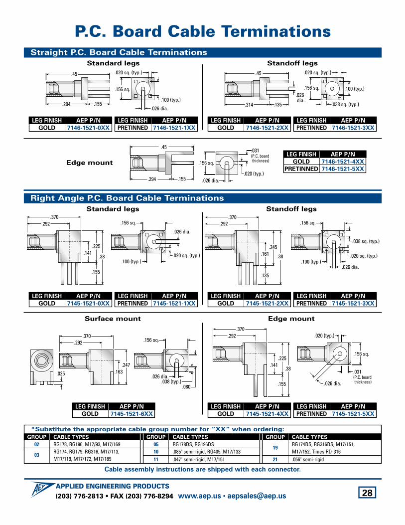
P.C. Board Cable TerminationsStraight P.C. Board Cable Terminations
Standard legs Standoff legs
.135
.45
.314
.100 (typ.)
.020 sq. (typ.)
.038 sq. (typ.)
.156 sq..026 dia.
.155
.45
.294.100 (typ.)
.020 sq. (typ.)
.156 sq.
.026 dia.
Edge mount
.155
.45
.294.020 (typ.)
.156 sq.
.026 dia.
.031(P.C. boardthickness)
Right Angle P.C. Board Cable Terminations
Standard legs Standoff legs
.161.245
.38
.135
.100 (typ.)
.156 sq..370
.292
.038 sq. (typ.)
.020 sq. (typ.)
.026 dia.
.370.292
.141.225
.38
.155
.100 (typ.).020 sq. (typ.)
.156 sq.
.026 dia.
LEG FINISH AEP P/N
GOLD 7146-1521-0XX
LEG FINISH AEP P/N
PRETINNED 7146-1521-1XX
LEG FINISH AEP P/N
GOLD 7146-1521-2XX
LEG FINISH AEP P/N
PRETINNED 7146-1521-3XX
LEG FINISH AEP P/N
GOLD 7145-1521-0XX
LEG FINISH AEP P/N
PRETINNED 7145-1521-1XX
LEG FINISH AEP P/N
GOLD 7145-1521-2XX
LEG FINISH AEP P/N
PRETINNED 7145-1521-3XX
Surface mount Edge mount
.370.292
.141.225
.38
.155
.020 (typ.)
.156 sq.
.026 dia.
.031(P.C. boardthickness)
.163.247
.038 (typ.).080
.156 sq.
.026 dia..025
.370.292
LEG FINISH AEP P/N
GOLD 7145-1521-6XX
LEG FINISH AEP P/N
GOLD 7146-1521-4XX
PRETINNED 7146-1521-5XX
LEG FINISH AEP P/N
GOLD 7145-1521-4XX
LEG FINISH AEP P/N
PRETINNED 7145-1521-5XX
*Substitute the appropriate cable group number for “XX” when ordering:
GROUP CABLE TYPES
02 RG178, RG196, M17/93, M17/169
03RG174, RG179, RG316, M17/113, M17/119, M17/172, M17/189
GROUP CABLE TYPES
05 RG178DS, RG196DS10 .085" semi-rigid, RG405, M17/13311 .047" semi-rigid, M17/151
GROUP CABLE TYPES
19RG174DS, RG316DS, M17/151,M17/152, Times RD-316
21 .056" semi-rigid
Cable assembly instructions are shipped with each connector.
(203) 776-2813 • FAX (203) 776-8294APPLIED ENGINEERING PRODUCTS
www.aep.us • [email protected] 29
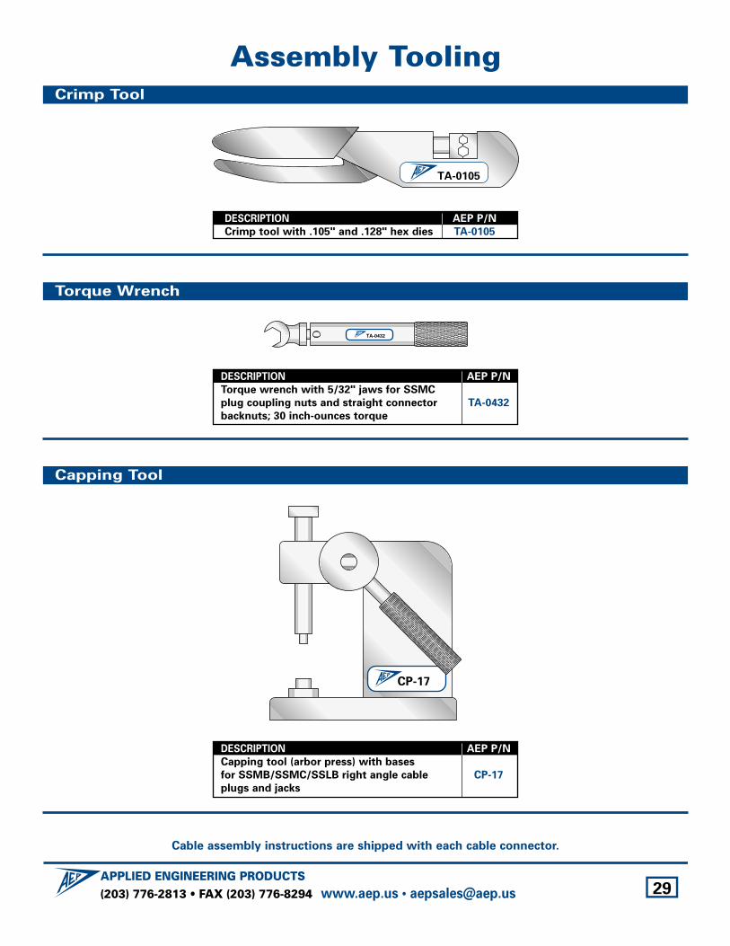
Assembly Tooling
TA-0105
TA-0432
DESCRIPTION AEP P/N
Crimp tool with .105" and .128" hex dies TA-0105
DESCRIPTION AEP P/N
Torque wrench with 5/32" jaws for SSMC
plug coupling nuts and straight connector TA-0432
backnuts; 30 inch-ounces torque
DESCRIPTION AEP P/N
Capping tool (arbor press) with bases
for SSMB/SSMC/SSLB right angle cable CP-17
plugs and jacks
CP-17
Crimp Tool
Torque Wrench
Capping Tool
Cable assembly instructions are shipped with each cable connector.
(203) 776-2813 • FAX (203) 776-8294APPLIED ENGINEERING PRODUCTS
www.aep.us • [email protected] 30
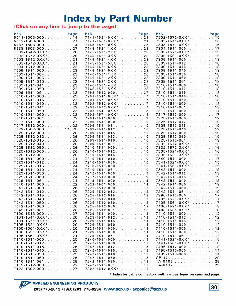
Index by Part Number(Click on any line to jump to the page)
P / N P a g e5 0 1 1 - 1 5 0 3 - 0 0 0 . . . . . . . . . 1 45 0 1 3 - 1 5 0 3 - 0 0 0 . . . . . . . . . 2 75 9 3 7 - 1 5 0 3 - 0 0 0 . . . . . . . . . 1 45 9 3 8 - 1 5 0 3 - 0 0 0 . . . . . . . . . 2 77 0 0 2 - 1 5 4 2 - 0 X X * . . . . . . . . 2 07 0 0 2 - 1 5 7 2 - 0 X X * . . . . . . . . 2 07 0 0 3 - 1 5 4 2 - 0 X X * . . . . . . . . 2 17 0 0 3 - 1 5 7 2 - 0 X X * . . . . . . . . 2 17 0 0 4 - 1 5 1 2 - 0 0 0 . . . . . . . . . 2 27 0 0 9 - 1 5 1 1 - 0 0 0 . . . . . . . . . 2 37 0 0 9 - 1 5 1 1 - 0 0 4 . . . . . . . . . 2 37 0 0 9 - 1 5 1 1 - 0 0 5 . . . . . . . . . 2 37 0 0 9 - 1 5 1 1 - 0 4 0 . . . . . . . . . 2 37 0 0 9 - 1 5 1 1 - 0 4 1 . . . . . . . . . 2 37 0 0 9 - 1 5 1 1 - 0 5 0 . . . . . . . . . 2 37 0 0 9 - 1 5 1 1 - 0 6 1 . . . . . . . . . 2 37 0 1 0 - 1 5 1 1 - 0 0 0 . . . . . . . . . 2 37 0 1 0 - 1 5 1 1 - 0 1 5 . . . . . . . . . 2 37 0 1 0 - 1 5 1 1 - 0 4 0 . . . . . . . . . 2 37 0 1 0 - 1 5 1 1 - 0 4 1 . . . . . . . . . 2 37 0 1 0 - 1 5 1 1 - 0 5 0 . . . . . . . . . 2 37 0 1 0 - 1 5 1 1 - 0 6 0 . . . . . . . . . 2 37 0 1 0 - 1 5 1 1 - 0 6 1 . . . . . . . . . 2 37 0 1 2 - 1 5 1 1 - 0 0 0 . . . . . . . . . 2 27 0 1 7 - 1 5 1 2 - 0 0 0 . . . . . . . . . 2 27 0 2 2 - 1 5 0 2 - 0 0 0 . . . . . . 1 4 , 2 57 0 2 5 - 1 5 1 2 - 0 0 0 . . . . . . . . . 2 67 0 2 5 - 1 5 1 2 - 0 1 2 . . . . . . . . . 2 67 0 2 5 - 1 5 1 2 - 0 1 5 . . . . . . . . . 2 67 0 2 5 - 1 5 1 2 - 0 4 0 . . . . . . . . . 2 67 0 2 5 - 1 5 1 2 - 0 5 0 . . . . . . . . . 2 67 0 2 5 - 1 5 1 2 - 0 6 0 . . . . . . . . . 2 67 0 2 5 - 1 5 1 2 - 0 6 1 . . . . . . . . . 2 67 0 2 9 - 1 5 1 1 - 0 0 0 . . . . . . . . . 2 47 0 2 9 - 1 5 1 1 - 0 1 2 . . . . . . . . . 2 47 0 2 9 - 1 5 1 1 - 0 1 5 . . . . . . . . . 2 47 0 2 9 - 1 5 1 1 - 0 4 0 . . . . . . . . . 2 47 0 2 9 - 1 5 1 1 - 0 5 0 . . . . . . . . . 2 47 0 2 9 - 1 5 1 1 - 0 6 0 . . . . . . . . . 2 47 0 2 9 - 1 5 1 1 - 0 6 1 . . . . . . . . . 2 47 0 4 0 - 1 5 1 1 - 0 0 0 . . . . . . . . . 2 27 0 4 2 - 1 5 1 1 - 0 0 0 . . . . . . . . . 2 67 0 4 2 - 1 5 1 1 - 0 1 2 . . . . . . . . . 2 67 0 4 2 - 1 5 1 1 - 0 1 5 . . . . . . . . . 2 67 0 4 2 - 1 5 1 1 - 0 4 0 . . . . . . . . . 2 67 0 4 2 - 1 5 1 1 - 0 5 0 . . . . . . . . . 2 67 0 4 2 - 1 5 1 1 - 0 6 0 . . . . . . . . . 2 67 0 4 2 - 1 5 1 1 - 0 6 1 . . . . . . . . . 2 67 1 0 0 - 1 5 1 3 - 0 0 0 . . . . . . . . . 2 77 1 0 1 - 1 5 4 1 - 0 X X * . . . . . . . . 2 07 1 0 1 - 1 5 7 1 - 0 X X * . . . . . . . . 2 07 1 0 5 - 1 5 2 1 - 0 X X * . . . . . . . . 2 07 1 0 5 - 1 5 6 1 - 0 X X * . . . . . . . . 2 07 1 0 6 - 1 5 2 1 - 0 X X * . . . . . . . . 2 17 1 0 6 - 1 5 6 1 - 0 X X * . . . . . . . . 2 17 1 1 0 - 1 5 1 1 - 0 0 0 . . . . . . . . . 2 57 1 1 0 - 1 5 1 1 - 0 1 2 . . . . . . . . . 2 57 1 1 0 - 1 5 1 1 - 0 1 5 . . . . . . . . . 2 57 1 1 0 - 1 5 1 1 - 0 4 0 . . . . . . . . . 2 57 1 1 0 - 1 5 1 1 - 0 5 0 . . . . . . . . . 2 57 1 1 0 - 1 5 1 1 - 0 6 0 . . . . . . . . . 2 57 1 1 0 - 1 5 1 1 - 0 6 1 . . . . . . . . . 2 57 1 1 9 - 1 5 1 2 - 0 0 0 . . . . . . . . . 2 27 1 2 2 - 1 5 0 2 - 0 0 0 . . . . . . . . . 2 7
P / N P a g e7 1 4 1 - 1 5 2 1 - 0 X X * . . . . . . . . 2 17 1 4 1 - 1 5 6 1 - 0 X X * . . . . . . . . 2 17 1 4 5 - 1 5 2 1 - 0 X X . . . . . . . . 2 87 1 4 5 - 1 5 2 1 - 1 X X . . . . . . . . 2 87 1 4 5 - 1 5 2 1 - 2 X X . . . . . . . . 2 87 1 4 5 - 1 5 2 1 - 3 X X . . . . . . . . 2 87 1 4 5 - 1 5 2 1 - 4 X X . . . . . . . . 2 87 1 4 5 - 1 5 2 1 - 5 X X . . . . . . . . 2 87 1 4 5 - 1 5 2 1 - 6 X X . . . . . . . . 2 87 1 4 6 - 1 5 2 1 - 0 X X . . . . . . . . 2 87 1 4 6 - 1 5 2 1 - 1 X X . . . . . . . . 2 87 1 4 6 - 1 5 2 1 - 2 X X . . . . . . . . 2 87 1 4 6 - 1 5 2 1 - 3 X X . . . . . . . . 2 87 1 4 6 - 1 5 2 1 - 4 X X . . . . . . . . 2 87 1 4 6 - 1 5 2 1 - 5 X X . . . . . . . . 2 87 1 9 8 - 1 5 1 3 - 0 0 0 . . . . . . . . . 2 77 2 0 1 - 1 5 4 1 - 0 X X * . . . . . . . . 77 2 0 1 - 1 5 7 1 - 0 X X * . . . . . . . . 77 2 0 2 - 1 5 4 2 - 0 X X * . . . . . . . . 77 2 0 2 - 1 5 7 2 - 0 X X * . . . . . . . . 77 2 0 3 - 1 5 4 1 - 0 X X * . . . . . . . . 87 2 0 3 - 1 5 7 1 - 0 X X * . . . . . . . . 87 2 0 4 - 1 5 1 1 - 0 0 0 . . . . . . . . . . 97 2 0 9 - 1 5 1 1 - 0 0 0 . . . . . . . . . 1 07 2 0 9 - 1 5 1 1 - 0 1 1 . . . . . . . . . 1 07 2 0 9 - 1 5 1 1 - 0 1 2 . . . . . . . . . 1 07 2 0 9 - 1 5 1 1 - 0 1 5 . . . . . . . . . 1 07 2 0 9 - 1 5 1 1 - 0 2 3 . . . . . . . . . 1 07 2 0 9 - 1 5 1 1 - 0 4 0 . . . . . . . . . 1 07 2 0 9 - 1 5 1 1 - 0 6 1 . . . . . . . . . 1 07 2 1 0 - 1 5 1 1 - 0 0 0 . . . . . . . . . 1 07 2 1 0 - 1 5 1 1 - 0 1 2 . . . . . . . . . 1 07 2 1 0 - 1 5 1 1 - 0 1 5 . . . . . . . . . 1 07 2 1 0 - 1 5 1 1 - 0 4 0 . . . . . . . . . 1 07 2 1 0 - 1 5 1 1 - 0 5 0 . . . . . . . . . 1 07 2 1 0 - 1 5 1 1 - 0 6 0 . . . . . . . . . 1 07 2 1 0 - 1 5 1 1 - 0 6 1 . . . . . . . . . 1 07 2 1 2 - 1 5 1 1 - 0 0 0 . . . . . . . . . . 97 2 1 7 - 1 5 1 2 - 0 0 0 . . . . . . . . . . 97 2 1 9 - 1 5 1 1 - 0 0 0 . . . . . . . . . . 97 2 2 2 - 1 5 0 1 - 0 0 0 . . . . . . . . . 1 47 2 2 5 - 1 5 1 2 - 0 0 0 . . . . . . . . . 1 37 2 2 5 - 1 5 1 2 - 0 1 2 . . . . . . . . . 1 37 2 2 5 - 1 5 1 2 - 0 1 5 . . . . . . . . . 1 37 2 2 5 - 1 5 1 2 - 0 4 0 . . . . . . . . . 1 37 2 2 5 - 1 5 1 2 - 0 5 0 . . . . . . . . . 1 37 2 2 5 - 1 5 1 2 - 0 6 0 . . . . . . . . . 1 37 2 2 5 - 1 5 1 2 - 0 6 1 . . . . . . . . . 1 37 2 2 9 - 1 5 1 1 - 0 0 0 . . . . . . . . . 1 17 2 2 9 - 1 5 1 1 - 0 1 2 . . . . . . . . . 1 17 2 2 9 - 1 5 1 1 - 0 1 5 . . . . . . . . . 1 17 2 2 9 - 1 5 1 1 - 0 4 0 . . . . . . . . . 1 17 2 2 9 - 1 5 1 1 - 0 5 0 . . . . . . . . . 1 17 2 2 9 - 1 5 1 1 - 0 6 0 . . . . . . . . . 1 17 2 2 9 - 1 5 1 1 - 0 6 1 . . . . . . . . . 1 17 2 4 0 - 1 5 1 1 - 0 0 0 . . . . . . . . . . 97 2 4 2 - 1 5 1 1 - 0 0 0 . . . . . . . . . 1 37 2 4 2 - 1 5 1 1 - 0 1 2 . . . . . . . . . 1 37 2 4 2 - 1 5 1 1 - 0 1 5 . . . . . . . . . 1 37 2 4 2 - 1 5 1 1 - 0 4 0 . . . . . . . . . 1 37 2 4 2 - 1 5 1 1 - 0 5 0 . . . . . . . . . 1 37 2 4 2 - 1 5 1 1 - 0 6 0 . . . . . . . . . 1 37 2 4 2 - 1 5 1 1 - 0 6 1 . . . . . . . . . 1 37 3 0 2 - 1 5 4 2 - 0 X X * . . . . . . . . 1 5
P / N P a g e7 3 0 2 - 1 5 7 2 - 0 X X * . . . . . . . . 1 57 3 0 3 - 1 5 4 1 - 0 X X * . . . . . . . . 1 67 3 0 3 - 1 5 7 1 - 0 X X * . . . . . . . . 1 67 3 0 4 - 1 5 1 1 - 0 0 0 . . . . . . . . . 1 77 3 0 5 - 1 5 2 1 - 0 X X * . . . . . . . . 1 57 3 0 5 - 1 5 6 1 - 0 X X * . . . . . . . . 1 57 3 0 9 - 1 5 1 1 - 0 0 0 . . . . . . . . . 1 87 3 0 9 - 1 5 1 1 - 0 1 2 . . . . . . . . . 1 87 3 0 9 - 1 5 1 1 - 0 1 5 . . . . . . . . . 1 87 3 0 9 - 1 5 1 1 - 0 4 0 . . . . . . . . . 1 87 3 0 9 - 1 5 1 1 - 0 5 0 . . . . . . . . . 1 87 3 0 9 - 1 5 1 1 - 0 6 0 . . . . . . . . . 1 87 3 0 9 - 1 5 1 1 - 0 6 1 . . . . . . . . . 1 87 3 1 0 - 1 5 1 1 - 0 0 0 . . . . . . . . . 1 87 3 1 0 - 1 5 1 1 - 0 1 2 . . . . . . . . . 1 87 3 1 0 - 1 5 1 1 - 0 1 5 . . . . . . . . . 1 87 3 1 0 - 1 5 1 1 - 0 4 0 . . . . . . . . . 1 87 3 1 0 - 1 5 1 1 - 0 5 0 . . . . . . . . . 1 87 3 1 0 - 1 5 1 1 - 0 6 0 . . . . . . . . . 1 87 3 1 0 - 1 5 1 1 - 0 6 1 . . . . . . . . . 1 87 3 1 2 - 1 5 1 1 - 0 0 0 . . . . . . . . . 1 77 3 1 7 - 1 5 1 2 - 0 0 0 . . . . . . . . . 1 77 3 2 5 - 1 5 1 2 - 0 0 0 . . . . . . . . . 1 97 3 2 5 - 1 5 1 2 - 0 1 2 . . . . . . . . . 1 97 3 2 5 - 1 5 1 2 - 0 1 5 . . . . . . . . . 1 97 3 2 5 - 1 5 1 2 - 0 4 0 . . . . . . . . . 1 97 3 2 5 - 1 5 1 2 - 0 5 0 . . . . . . . . . 1 97 3 2 5 - 1 5 1 2 - 0 6 0 . . . . . . . . . 1 97 3 2 5 - 1 5 1 2 - 0 6 1 . . . . . . . . . 1 97 3 3 2 - 1 5 7 2 - 0 X X * . . . . . . . . 1 67 3 3 2 - 1 5 7 2 - 3 X X * . . . . . . . . 1 67 3 3 5 - 1 5 2 1 - 0 X X * . . . . . . . . 1 67 3 3 5 - 1 5 2 1 - 3 X X * . . . . . . . . 1 67 3 4 0 - 1 5 1 1 - 0 0 0 . . . . . . . . . 1 77 3 4 1 - 1 5 2 1 - 0 X X * . . . . . . . . 1 57 3 4 1 - 1 5 6 1 - 0 X X * . . . . . . . . 1 57 3 4 2 - 1 5 1 1 - 0 0 0 . . . . . . . . . 1 97 3 4 2 - 1 5 1 1 - 0 1 2 . . . . . . . . . 1 97 3 4 2 - 1 5 1 1 - 0 1 5 . . . . . . . . . 1 97 3 4 2 - 1 5 1 1 - 0 4 0 . . . . . . . . . 1 97 3 4 2 - 1 5 1 1 - 0 5 0 . . . . . . . . . 1 97 3 4 2 - 1 5 1 1 - 0 6 0 . . . . . . . . . 1 97 3 4 2 - 1 5 1 1 - 0 6 1 . . . . . . . . . 1 97 3 9 6 - 1 5 1 2 - 0 0 0 . . . . . . . . . 1 77 4 0 5 - 1 5 2 1 - 0 X X * . . . . . . . . 77 4 0 5 - 1 5 6 1 - 0 X X * . . . . . . . . 77 4 0 6 - 1 5 2 1 - 0 X X * . . . . . . . . 87 4 0 6 - 1 5 6 1 - 0 X X * . . . . . . . . 87 4 1 0 - 1 5 1 1 - 0 0 0 . . . . . . . . . 1 27 4 1 0 - 1 5 1 1 - 0 1 2 . . . . . . . . . 1 27 4 1 0 - 1 5 1 1 - 0 1 5 . . . . . . . . . 1 27 4 1 0 - 1 5 1 1 - 0 4 0 . . . . . . . . . 1 27 4 1 0 - 1 5 1 1 - 0 5 0 . . . . . . . . . 1 27 4 1 0 - 1 5 1 1 - 0 6 0 . . . . . . . . . 1 27 4 1 0 - 1 5 1 1 - 0 6 1 . . . . . . . . . 1 27 4 4 1 - 1 5 2 1 - 0 X X * . . . . . . . . 87 4 4 1 - 1 5 6 1 - 0 X X * . . . . . . . . 87 4 9 6 - 1 5 1 2 - 0 0 0 . . . . . . . . . . 97 4 9 8 - 1 5 1 3 - 0 0 0 . . . . . . . . . 1 47 4 9 9 - 1 5 1 3 - 0 0 0 . . . . . . . . . 1 4C P - 1 7 . . . . . . . . . . . . . . . 2 9TA - 0 1 0 5 . . . . . . . . . . . . . 2 9TA - 0 4 3 2 . . . . . . . . . . . . . 2 9
* Indicates cable connectors with various types on specified page.

Cata
log
# 12
7-7p
df R
ev.2
8/0
5
About AEPSince our foundation in 1973, our goal has been to tailor our equipment and processes toward satisfying customer and market demand, no matter how circumstances change. To that end, our modern plant, with recent expansion, provides vertically-integrated machining, assembly, and testing to ensure the product quality and on-time delivery that have always been our hallmark. “Continuous Improvement Equals Customer Satisfaction” is not just a slogan; we believe it’s the best and only way to do business.
Other AEP ProductsThe connectors in this brochure are only part of our complete line of coaxial connectors and cable assemblies, including: • SMA • SMB • SMC • SMP • SSMA • SLB (Slide-on version of SMB) • MCX • MMCX • 75Ω Miniature SMB • 75Ω Snap-on mating • 75Ω Screw-on mating • Adapters within and between series • Waterproof connectors• Flexible cable assemblies • Semi-rigid cable assemblies • And over 100 styles of MIL-PRF-39012 QPL connectors
in series SMA, SMB, and SMC.
APPLIED ENGINEERING PRODUCTS104 John W. Murphy Drive • P.O. Box 510 • New Haven, CT 06513
(203) 776-2813 • FAX (203) 776-8294 • www.aep.us • e-mail: [email protected] 31