Embed Size (px)
Citation preview
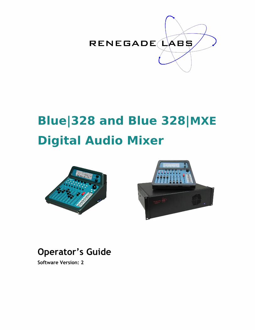
Blue|328 and Blue 328|MXE
Digital Audio Mixer
Operator’s GuideSoftware Version: 2
Renegade Labs Blue|328
Publishing and Copyright InformationBlue|328 and Blue 328|MXE Operator’s Guide
Part Number 070-44000
Publishing History
Revision 5: November, 2012
Copyright
© Renegade Labs, Inc. 2005 - 2012. All rights reserved. No part of this publication may be reproduced, transmitted, transcribed, stored in a retrieval system, or translated into any languages in any form by any means without the written permission of Renegade Labs.
Notice
Information contained in this document is not guaranteed and is subject to change without notice or obligation, and does not represent a commitment on the part of Renegade Labs, Inc.
Company Information
Renegade Labs, Inc.P.O. Box 86 Cedar Ridge, California 95924United States of America
Voice: +(530) 273-7047 Fax: +(530) 271-0757Web: www.renegadelabs.com email: [email protected]
Page 2
Operator’s Guide
Table of Contents
About this Operator’s Guide.........................................................................................5
Overview of the Blue|328 Mixer...................................................................................6Overview of the Blue|328.......................................................................................6About the Blue|328.................................................................................................7Blue|328 Audio Block Diagram...............................................................................8
Control Descriptions.....................................................................................................9Control Panel Overview..........................................................................................9The Blue|328 Control Panel Layout.........................................................................9Display Controls...................................................................................................10Monitor Control Section........................................................................................11Button, Pan, and Fader Rows................................................................................12Fader Strips .........................................................................................................12Master Fader .......................................................................................................15Multi-Function Keypad..........................................................................................16
Introducing Views and Menus ....................................................................................18Views vs. Menus ..................................................................................................18Navigating Views and Menus................................................................................19
LCD Views .................................................................................................................21LCD View Tree......................................................................................................21Overview..............................................................................................................21Main View.............................................................................................................22Route View...........................................................................................................25Meter View...........................................................................................................26Fader Level View..................................................................................................28
System Adjustments and Information Display............................................................29System Menu Tree................................................................................................29Accessing the System Menus...............................................................................29Assigning Record Returns.....................................................................................30Adjusting the Headphone Output.........................................................................31Enable/Disable TONE............................................................................................33Selecting Reference Sync.....................................................................................33Making Digital Audio Adjustments........................................................................34Adjusting Panel LED Intensity and Panel Modes...................................................35Displaying System Information.............................................................................36Configuring Output Functionality..........................................................................36View and Adjusting Module Parameters................................................................42Loudness Monitoring............................................................................................47
Making Fader Assignments .......................................................................................50Making Fader Input Assignments .........................................................................50Setting Up Fader Output Routing .........................................................................53
Applying Audio Effects...............................................................................................56Applying Equalization...........................................................................................57Applying Dynamics ..............................................................................................59Overview of Dynamics Controls ...........................................................................60Applying Audio Delay ..........................................................................................65Applying Phase Reversal......................................................................................67Enabling Clean Feed ............................................................................................68Adjusting Input Gain Trim ....................................................................................70
Monitoring Control.....................................................................................................71
Page 3
Renegade Labs Blue|328
Monitoring Program Bus.......................................................................................71Setting Up Solo bus Monitoring.............................................................................71Monitoring Record Returns...................................................................................71Setting up the Monitor Mode................................................................................72
Memory Save/Recall ..................................................................................................80What is stored during a Memory Save..................................................................80Memory Save/Recall Operations...........................................................................81
USB Register Management (328|MXE only)................................................................84USB Register Management Overview...................................................................84Register Management Menu.................................................................................84Transfer Registers To/From USB Memory Device..................................................84Deleting Registers................................................................................................87Rename or Create new USB directory..................................................................88USB Register Directory Overview.........................................................................89Software Upgrade using USB Memory Device......................................................89
Appendix A: Installation Information..........................................................................91Input/Output Configuration...................................................................................91Mixer Rear Panel Detail .......................................................................................91
Appendix B: Assigning Single Channels......................................................................93
Appendix C: Diagnostic Port/GPI Option.....................................................................94Diagnostics Port...................................................................................................94GPI Interface (Optional)........................................................................................95
Index .........................................................................................................................97
Page 4
Operator’s Guide
About this Operator’s Guide
Welcome to the Blue|328 and Blue 328|MXE digital audio mixers! The Blue|328 and the Blue 328|MXE operations are exactly the same other than the Blue 328|MXE includes the ability to transfer registers to and from a USB memory device. This Operator’s Guide refers to all operations as Blue|328 with the exception of the section pertaining to the Blue 328|MXE USB register management.
Note
To get up and running immediately, please consult the JumpStart Guide.
For detailed installation information, for example how to add input or output modules to your mixer, please consult the Installation Guide.
This Operator’s Guide covers the following subjects:
• Overviews
• Control Descriptions
• LCD View and Menu Descriptions
• System adjustments and Information Display
• Fader Assignments
• Applying Audio Effects
• Monitoring Control
• Memory Save/Recall
• USB Register Management for Blue 328|MXE only.
This guide also includes an appendix containing some installation details you may need to refer to from time to time.
About this Operator’s Guide Page 5
Renegade Labs Blue|328
Overview of the Blue|328 Mixer
Overview of the Blue|328
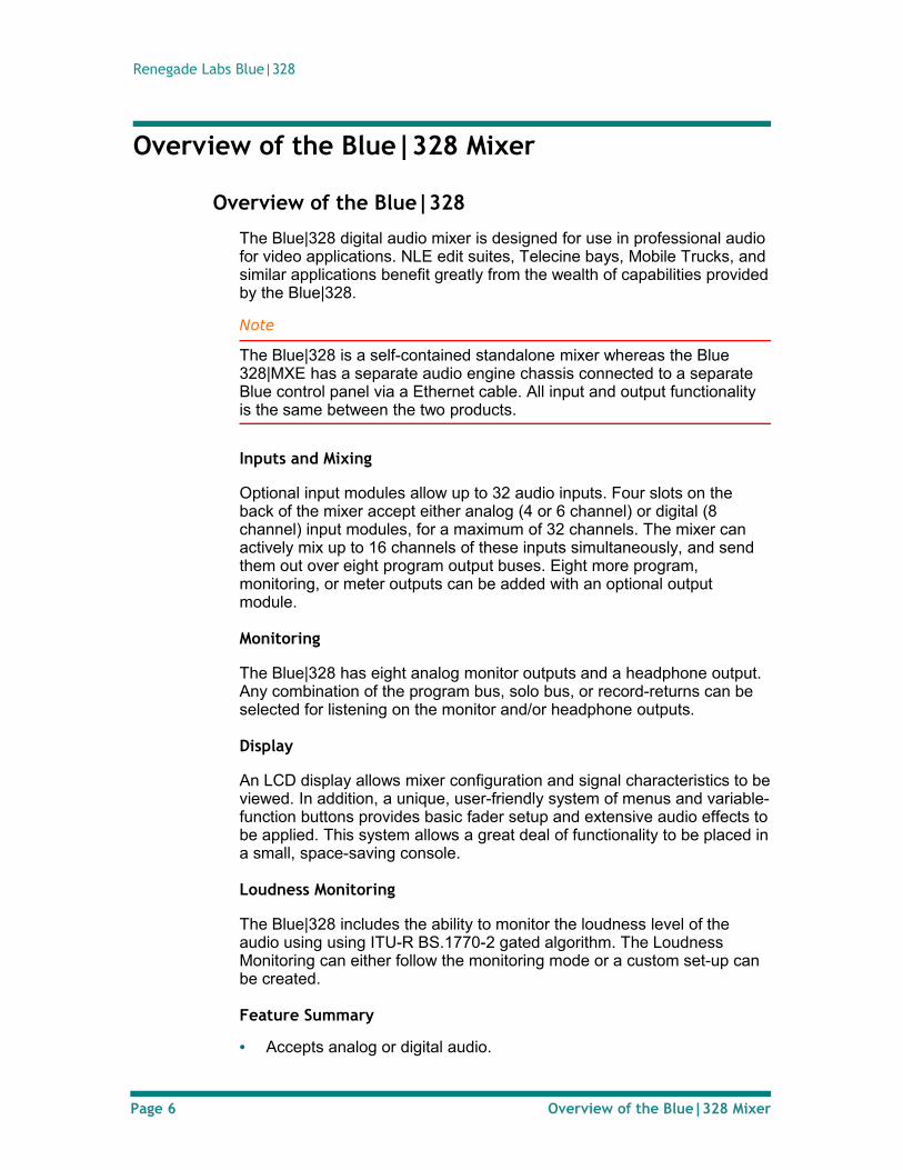
The Blue|328 digital audio mixer is designed for use in professional audio for video applications. NLE edit suites, Telecine bays, Mobile Trucks, and similar applications benefit greatly from the wealth of capabilities provided by the Blue|328.
Note
The Blue|328 is a self-contained standalone mixer whereas the Blue 328|MXE has a separate audio engine chassis connected to a separate Blue control panel via a Ethernet cable. All input and output functionality is the same between the two products.
Inputs and Mixing
Optional input modules allow up to 32 audio inputs. Four slots on the back of the mixer accept either analog (4 or 6 channel) or digital (8 channel) input modules, for a maximum of 32 channels. The mixer can actively mix up to 16 channels of these inputs simultaneously, and send them out over eight program output buses. Eight more program, monitoring, or meter outputs can be added with an optional output module.
Monitoring
The Blue|328 has eight analog monitor outputs and a headphone output. Any combination of the program bus, solo bus, or record-returns can be selected for listening on the monitor and/or headphone outputs.
Display
An LCD display allows mixer configuration and signal characteristics to be viewed. In addition, a unique, user-friendly system of menus and variable-function buttons provides basic fader setup and extensive audio effects to be applied. This system allows a great deal of functionality to be placed in a small, space-saving console.
Loudness Monitoring
The Blue|328 includes the ability to monitor the loudness level of the audio using using ITU-R BS.1770-2 gated algorithm. The Loudness Monitoring can either follow the monitoring mode or a custom set-up can be created.
Feature Summary
• Accepts analog or digital audio.
Page 6 Overview of the Blue|328 Mixer
Operator’s Guide
• Digital inputs may be AES or SD/HD SDI (serial digital with embedded audio).
• Accepts up to 32 input channels with optional input modules.
• Mixes 16 channels simultaneously.
• Has eight program outputs.
• Loudness Monitoring using ITU-R BS.1770-2 gated algorithm.
• Has eight highly configurable monitor and stereo headphone outputs.
• Optional output module can be added for additional program, monitor, or meter outputs.
• Has powerful LCD menu system with space-saving variable-function buttons for fader setup and applying audio effects.
About the Blue|328
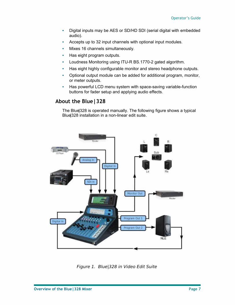
The Blue|328 is operated manually. The following figure shows a typical Blue|328 installation in a non-linear edit suite.
Figure 1. Blue|328 in Video Edit Suite
Overview of the Blue|328 Mixer Page 7
Renegade Labs Blue|328
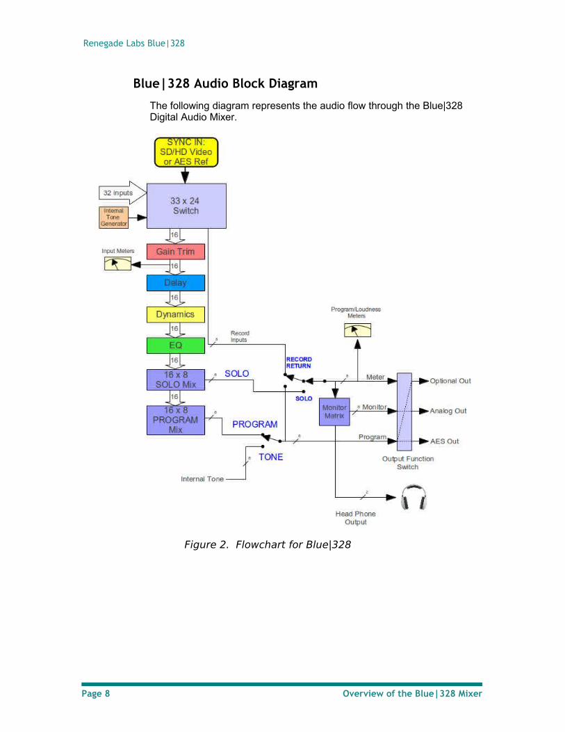
Blue|328 Audio Block Diagram
The following diagram represents the audio flow through the Blue|328 Digital Audio Mixer.
Figure 2. Flowchart for Blue|328
Page 8 Overview of the Blue|328 Mixer
Operator’s Guide
Control Descriptions
Control Panel Overview
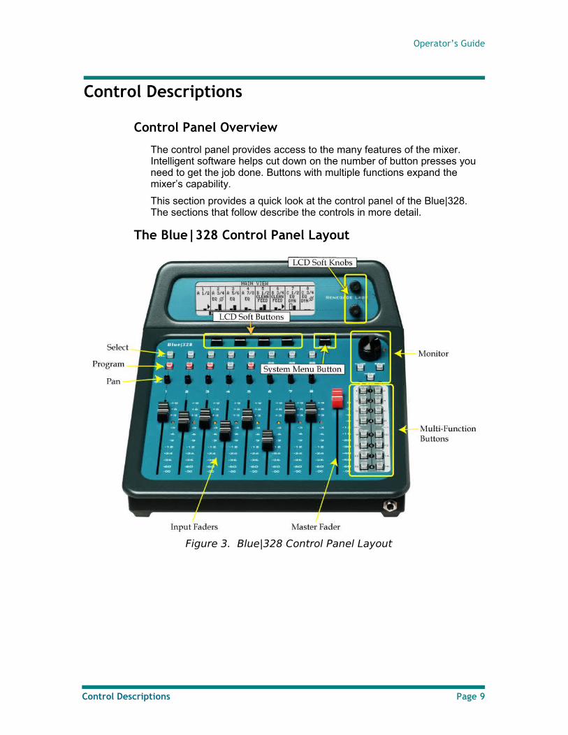
The control panel provides access to the many features of the mixer. Intelligent software helps cut down on the number of button presses you need to get the job done. Buttons with multiple functions expand the mixer’s capability.
This section provides a quick look at the control panel of the Blue|328. The sections that follow describe the controls in more detail.
The Blue|328 Control Panel Layout
Figure 3. Blue|328 Control Panel Layout
Control Descriptions Page 9
Renegade Labs Blue|328
Display Controls
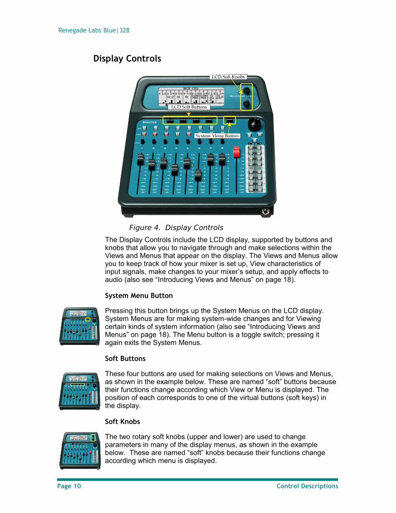
Figure 4. Display Controls
The Display Controls include the LCD display, supported by buttons and knobs that allow you to navigate through and make selections within the Views and Menus that appear on the display. The Views and Menus allow you to keep track of how your mixer is set up, View characteristics of input signals, make changes to your mixer’s setup, and apply effects to audio (also see “Introducing Views and Menus” on page 18).
System Menu Button
Pressing this button brings up the System Menus on the LCD display. System Menus are for making system-wide changes and for Viewing certain kinds of system information (also see “Introducing Views and Menus” on page 18). The Menu button is a toggle switch; pressing it again exits the System Menus.
Soft Buttons
These four buttons are used for making selections on Views and Menus, as shown in the example below. These are named “soft” buttons because their functions change according which View or Menu is displayed. The position of each corresponds to one of the virtual buttons (soft keys) in the display.
Soft Knobs
The two rotary soft knobs (upper and lower) are used to change parameters in many of the display menus, as shown in the example below. These are named “soft” knobs because their functions change according which menu is displayed.
Page 10 Control Descriptions
Operator’s Guide
Monitor Control Section
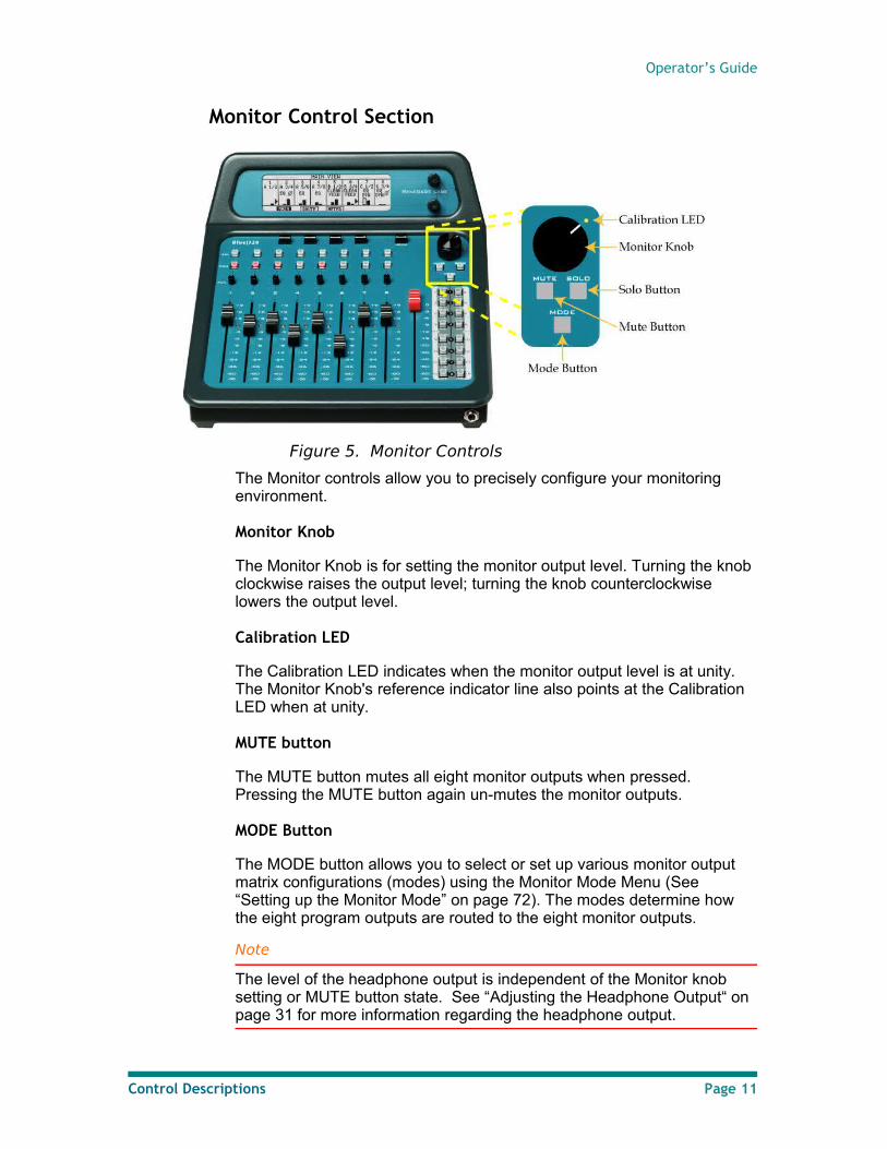
Figure 5. Monitor Controls
The Monitor controls allow you to precisely configure your monitoring environment.
Monitor Knob
The Monitor Knob is for setting the monitor output level. Turning the knob clockwise raises the output level; turning the knob counterclockwise lowers the output level.
Calibration LED
The Calibration LED indicates when the monitor output level is at unity. The Monitor Knob's reference indicator line also points at the Calibration LED when at unity.
MUTE button
The MUTE button mutes all eight monitor outputs when pressed. Pressing the MUTE button again un-mutes the monitor outputs.
MODE Button
The MODE button allows you to select or set up various monitor output matrix configurations (modes) using the Monitor Mode Menu (See “Setting up the Monitor Mode” on page 72). The modes determine how the eight program outputs are routed to the eight monitor outputs.
Note
The level of the headphone output is independent of the Monitor knob setting or MUTE button state. See “Adjusting the Headphone Output“ on page 31 for more information regarding the headphone output.
Control Descriptions Page 11
Renegade Labs Blue|328
SOLO Button
On the Blue|328, the SOLO button allows you to monitor one or more selected faders separately from the entire mix. The program outputs are not affected.
When pressed, normal monitoring is interrupted and the solo mode is entered. The Select buttons are used to select which fader(s) will be monitored. The SOLO button is toggle on/off; pressing it again will exit the solo mode and return normal program output monitoring.
Note
The solo output routing follows fader output routing.
SOLO will override the Record Return monitoring when enable. Refer to “Assigning Record Returns“ on page 30 for additional information.
• Also see “Setting Up Solo bus Monitoring” on page 71.
Button, Pan, and Fader Rows
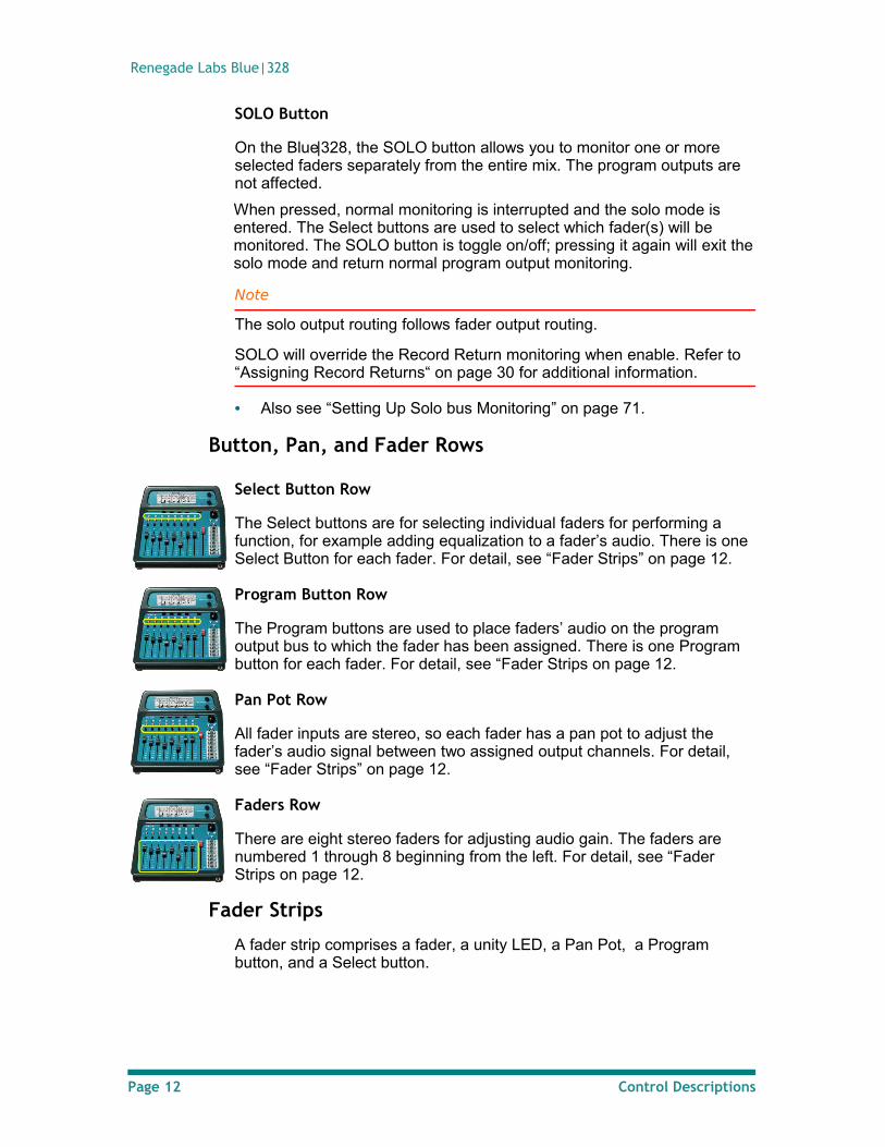
Select Button Row
The Select buttons are for selecting individual faders for performing a function, for example adding equalization to a fader’s audio. There is one Select Button for each fader. For detail, see “Fader Strips” on page 12.
Program Button Row
The Program buttons are used to place faders’ audio on the program output bus to which the fader has been assigned. There is one Program button for each fader. For detail, see “Fader Strips on page 12.
Pan Pot Row
All fader inputs are stereo, so each fader has a pan pot to adjust the fader’s audio signal between two assigned output channels. For detail, see “Fader Strips” on page 12.
Faders Row
There are eight stereo faders for adjusting audio gain. The faders are numbered 1 through 8 beginning from the left. For detail, see “Fader Strips on page 12.
Fader Strips
A fader strip comprises a fader, a unity LED, a Pan Pot, a Program button, and a Select button.
Page 12 Control Descriptions
Operator’s Guide
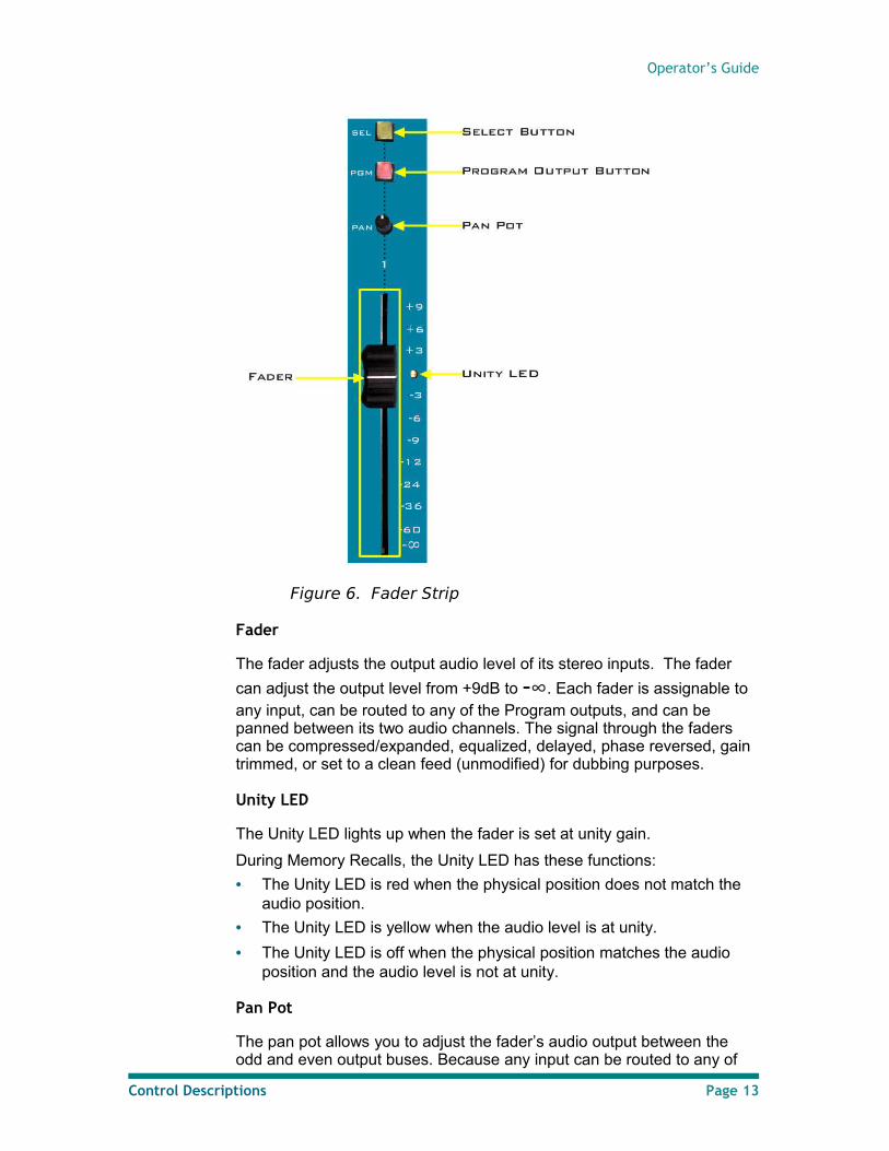
Figure 6. Fader Strip
Fader
The fader adjusts the output audio level of its stereo inputs. The fader
can adjust the output level from +9dB to -∞. Each fader is assignable to any input, can be routed to any of the Program outputs, and can be panned between its two audio channels. The signal through the faders can be compressed/expanded, equalized, delayed, phase reversed, gain trimmed, or set to a clean feed (unmodified) for dubbing purposes.
Unity LED
The Unity LED lights up when the fader is set at unity gain.
During Memory Recalls, the Unity LED has these functions:
• The Unity LED is red when the physical position does not match the audio position.
• The Unity LED is yellow when the audio level is at unity.
• The Unity LED is off when the physical position matches the audio position and the audio level is not at unity.
Pan Pot
The pan pot allows you to adjust the fader’s audio output between the odd and even output buses. Because any input can be routed to any of
Control Descriptions Page 13
Renegade Labs Blue|328
the eight output buses, the behavior this seemingly simple pan can be complicated.
As an example, consider the usual case where output bus 1 is the left monitor output and output bus 2 is the right monitor output. Suppose the left input is routed to output bus 1 only, and the right input is selected on bus 2 only. Turning the pan knob fully counterclockwise would yield only left input audio from the left speaker. With the pan knob fully clockwise, we would hear only right input audio from the right speaker.
However, if you route the left input channel of the fader to output bus 2 and the right input channel to output bus 1, the pan pot may behave differently than you expect. Turning the pan knob fully counterclockwise yields the right input channel only in the left speaker. This is due to the right input channel being routed to the odd numbered output channel. Since the pan knob works based on the assigned output channels, whichever source is routed to the odd output channels is what is heard.
Turning the pan knob fully clockwise yields the left input channel only in the right speaker. This is due to the left input channel being routed to the even numbered output channel. Since the pan knob works based on the assigned output channels, whichever source is routed to the even output channels is what is heard.
Program Button
The Program button places the fader’s output onto the program bus. The specific program outputs on which the fader’s channels will appear is determined by the output routing for the fader. See “Setting Up Fader Output Routing “on page 53.
The Program button is toggle on/off. The Program button indicates that its associated fader is on the Program bus by lighting up.
Select Button
The Select button has various functions with regard to its associated fader, for example:
• Selecting the fader for certain operations, for example applying audio effects.
• Bringing up menus for making changes to the fader’s audio input signals. If no input is assigned to the fader, pressing the Select button
brings up the Input Assignment Menu on the display. If the fader has inputs assigned to it, the Select button accesses
the various menus, with the Route Menu as the default menu.
The Select button is a toggle on/off. When the Select button is active, it is illuminated.
Note
De-selecting the Select button in a menu sequence often is equivalent to pressing the enter key on a pc. It can cause changes to be accepted.
Page 14 Control Descriptions
Operator’s Guide
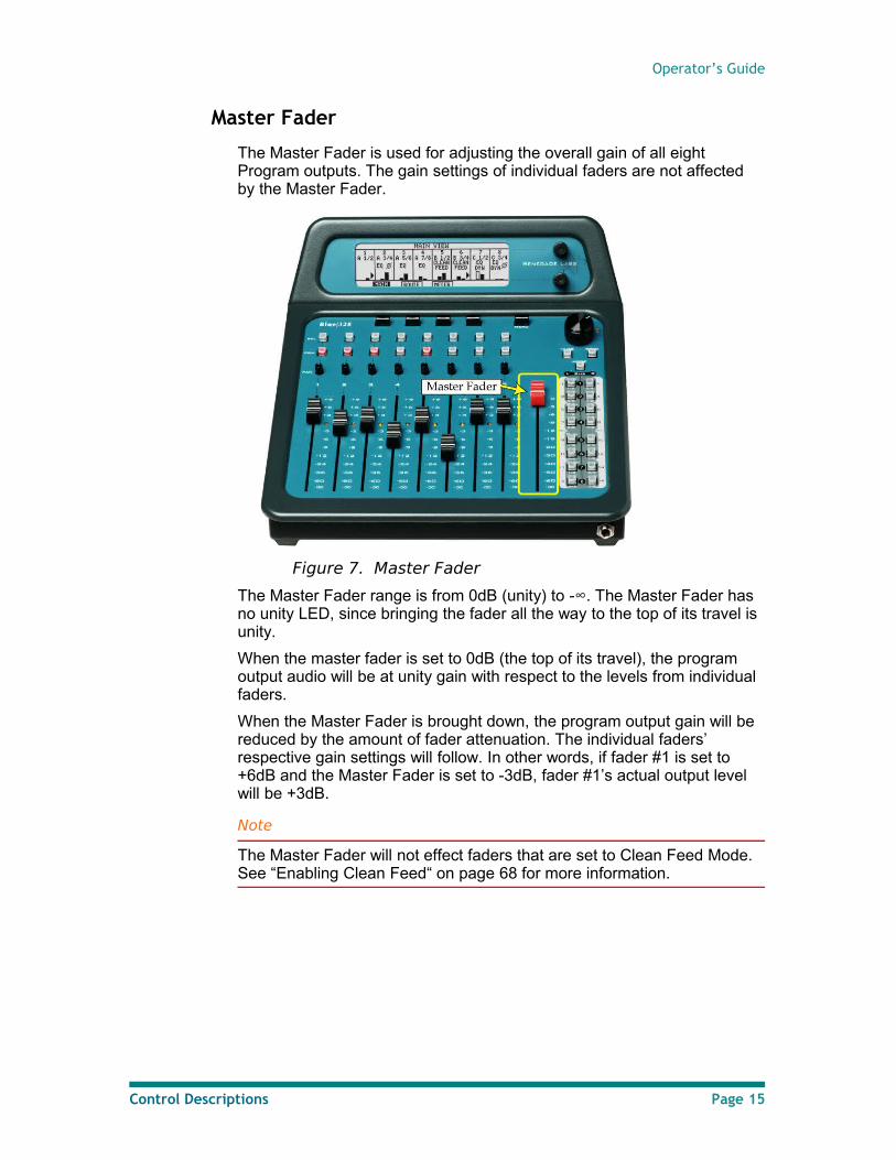
Master Fader
The Master Fader is used for adjusting the overall gain of all eight Program outputs. The gain settings of individual faders are not affected by the Master Fader.
Figure 7. Master Fader
The Master Fader range is from 0dB (unity) to -∞. The Master Fader has no unity LED, since bringing the fader all the way to the top of its travel is unity.
When the master fader is set to 0dB (the top of its travel), the program output audio will be at unity gain with respect to the levels from individual faders.
When the Master Fader is brought down, the program output gain will be reduced by the amount of fader attenuation. The individual faders’ respective gain settings will follow. In other words, if fader #1 is set to +6dB and the Master Fader is set to -3dB, fader #1’s actual output level will be +3dB.
Note
The Master Fader will not effect faders that are set to Clean Feed Mode. See “Enabling Clean Feed“ on page 68 for more information.
Control Descriptions Page 15
Renegade Labs Blue|328
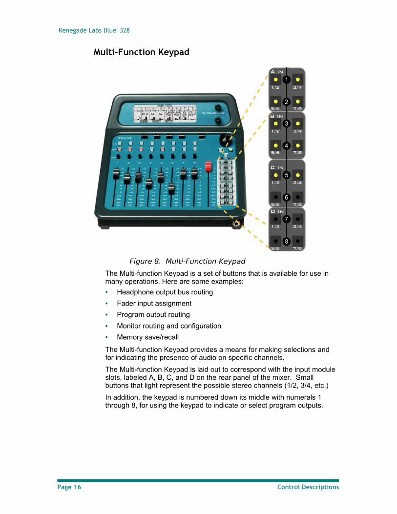
Multi-Function Keypad
Figure 8. Multi-Function Keypad
The Multi-function Keypad is a set of buttons that is available for use in many operations. Here are some examples:
• Headphone output bus routing
• Fader input assignment
• Program output routing
• Monitor routing and configuration
• Memory save/recall
The Multi-function Keypad provides a means for making selections and for indicating the presence of audio on specific channels.
The Multi-function Keypad is laid out to correspond with the input module slots, labeled A, B, C, and D on the rear panel of the mixer. Small buttons that light represent the possible stereo channels (1/2, 3/4, etc.)
In addition, the keypad is numbered down its middle with numerals 1 through 8, for using the keypad to indicate or select program outputs.
Page 16 Control Descriptions
Operator’s Guide
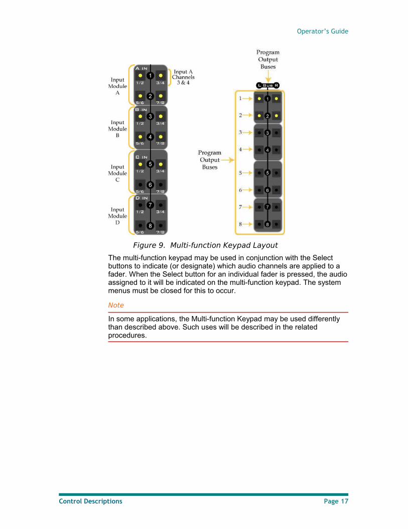
Figure 9. Multi-function Keypad Layout
The multi-function keypad may be used in conjunction with the Select buttons to indicate (or designate) which audio channels are applied to a fader. When the Select button for an individual fader is pressed, the audio assigned to it will be indicated on the multi-function keypad. The system menus must be closed for this to occur.
Note
In some applications, the Multi-function Keypad may be used differently than described above. Such uses will be described in the related procedures.
Control Descriptions Page 17
Renegade Labs Blue|328
Introducing Views and Menus
The LCD screen on the Blue|328 can display control panel configurations and many signal conditions. It can also display menus that allow you to make changes. There are two types of displays, Views and Menus.
Views vs. Menus
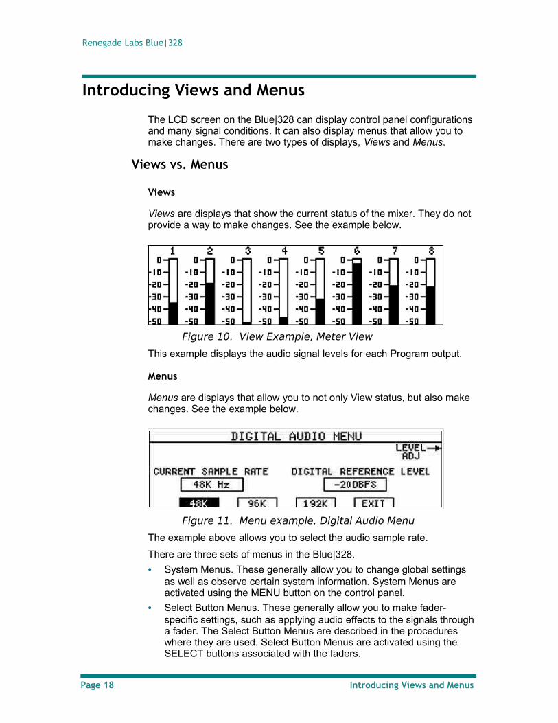
Views
Views are displays that show the current status of the mixer. They do not provide a way to make changes. See the example below.
Figure 10. View Example, Meter View
This example displays the audio signal levels for each Program output.
Menus
Menus are displays that allow you to not only View status, but also make changes. See the example below.
Figure 11. Menu example, Digital Audio Menu
The example above allows you to select the audio sample rate.
There are three sets of menus in the Blue|328.
• System Menus. These generally allow you to change global settings as well as observe certain system information. System Menus are activated using the MENU button on the control panel.
• Select Button Menus. These generally allow you to make fader-specific settings, such as applying audio effects to the signals through a fader. The Select Button Menus are described in the procedures where they are used. Select Button Menus are activated using the SELECT buttons associated with the faders.
Page 18 Introducing Views and Menus
Operator’s Guide
• Monitor Mode Menus. These allow you to set the output matrix that feeds the monitor outputs. The Monitor Mode Menus are described in Setting up the Monitor Mode on page 72. Monitor Mode Menus are activated by pressing the MODE button in the Monitor section of the control panel.
Navigating Views and Menus
Basic Navigation
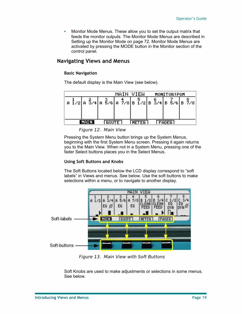
The default display is the Main View (see below).
Figure 12. Main View
Pressing the System Menu button brings up the System Menus, beginning with the first System Menu screen. Pressing it again returns you to the Main View. When not in a System Menu, pressing one of the fader Select buttons places you in the Select Menus.
Using Soft Buttons and Knobs
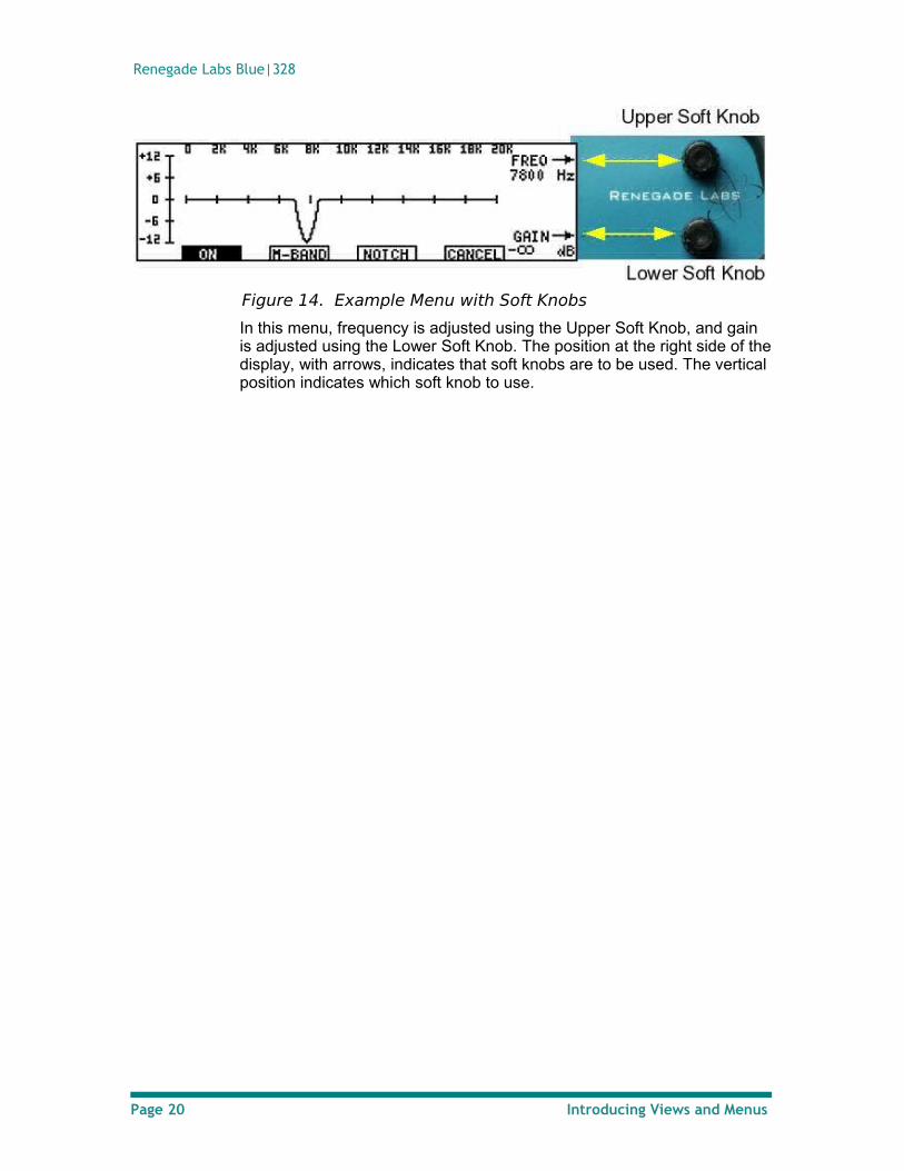
The Soft Buttons located below the LCD display correspond to “soft labels” in Views and menus. See below. Use the soft buttons to make selections within a menu, or to navigate to another display.
Figure 13. Main View with Soft Buttons
Soft Knobs are used to make adjustments or selections in some menus. See below.
Introducing Views and Menus Page 19
Renegade Labs Blue|328
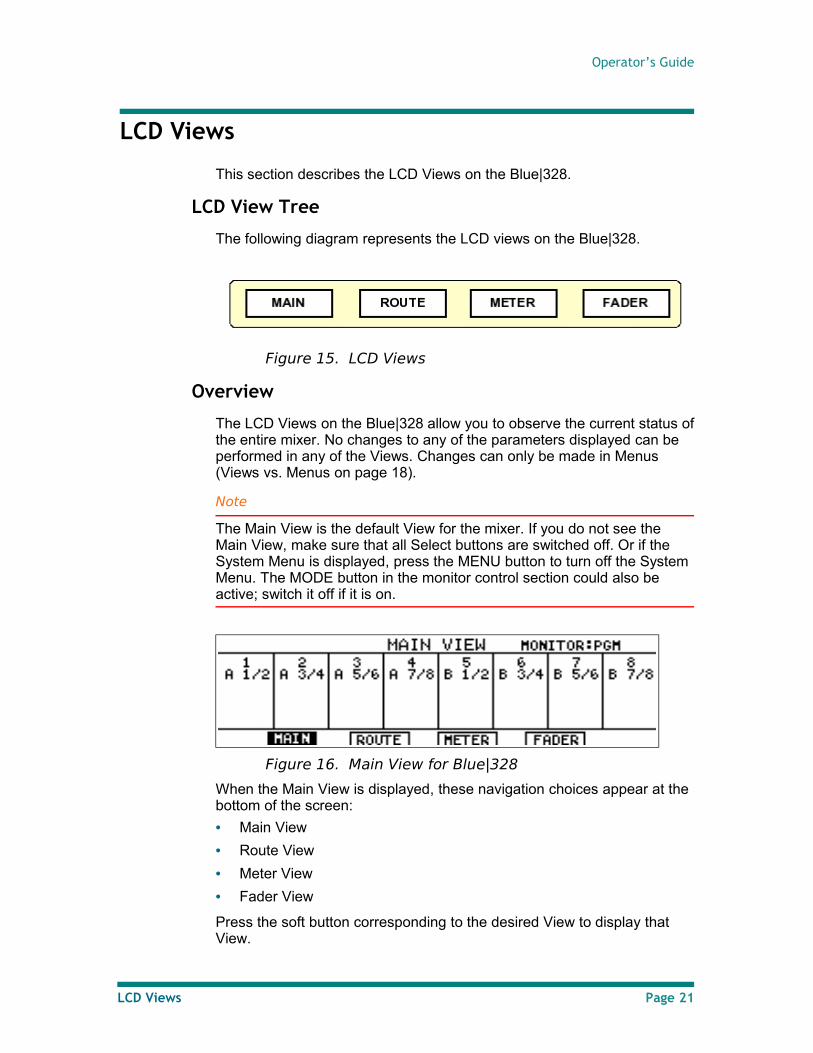
Figure 14. Example Menu with Soft Knobs
In this menu, frequency is adjusted using the Upper Soft Knob, and gain is adjusted using the Lower Soft Knob. The position at the right side of the display, with arrows, indicates that soft knobs are to be used. The vertical position indicates which soft knob to use.
Page 20 Introducing Views and Menus
Operator’s Guide
LCD Views
This section describes the LCD Views on the Blue|328.
LCD View Tree
The following diagram represents the LCD views on the Blue|328.
Figure 15. LCD Views
Overview
The LCD Views on the Blue|328 allow you to observe the current status of the entire mixer. No changes to any of the parameters displayed can be performed in any of the Views. Changes can only be made in Menus (Views vs. Menus on page 18).
Note
The Main View is the default View for the mixer. If you do not see the Main View, make sure that all Select buttons are switched off. Or if the System Menu is displayed, press the MENU button to turn off the System Menu. The MODE button in the monitor control section could also be active; switch it off if it is on.
Figure 16. Main View for Blue|328
When the Main View is displayed, these navigation choices appear at the bottom of the screen:
• Main View
• Route View
• Meter View
• Fader View
Press the soft button corresponding to the desired View to display that View.
LCD Views Page 21
Renegade Labs Blue|328
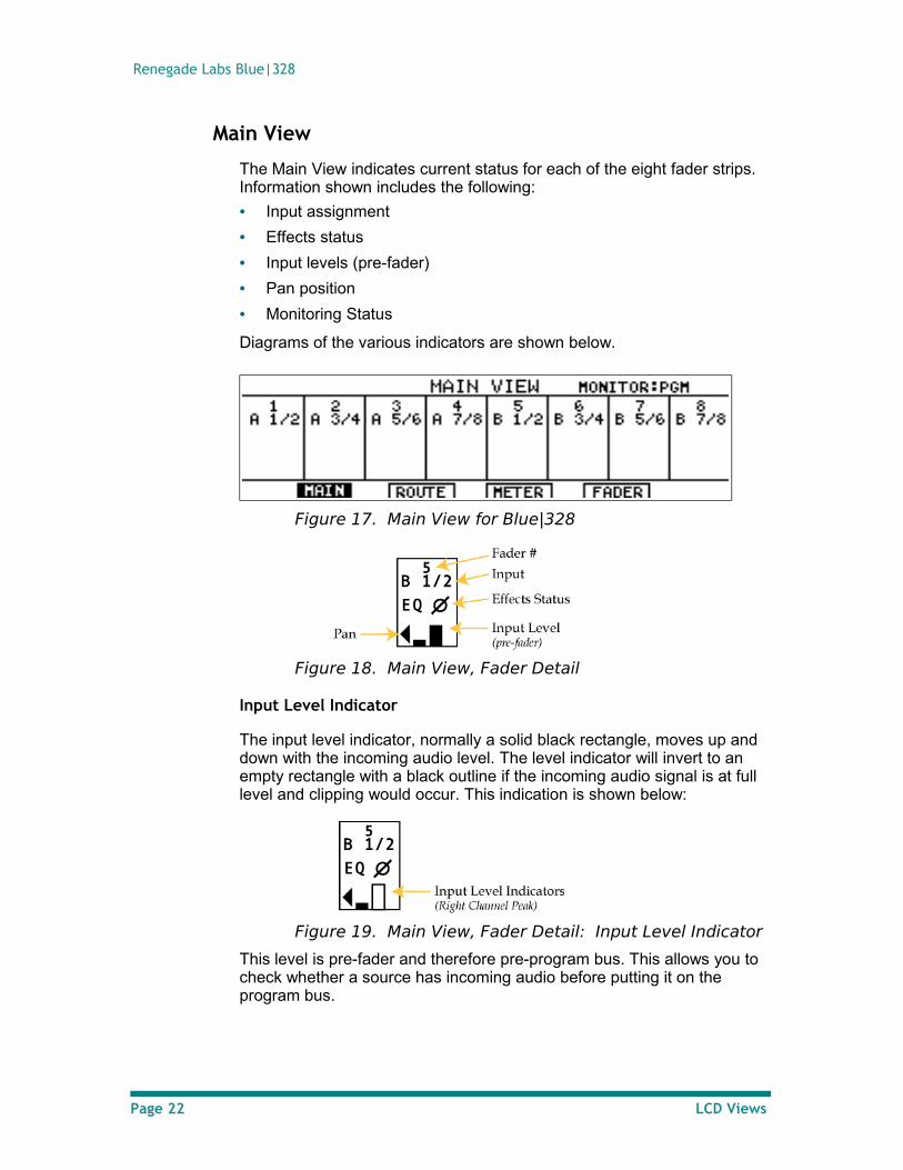
Main View
The Main View indicates current status for each of the eight fader strips. Information shown includes the following:
• Input assignment
• Effects status
• Input levels (pre-fader)
• Pan position
• Monitoring Status
Diagrams of the various indicators are shown below.
Figure 17. Main View for Blue|328
Figure 18. Main View, Fader Detail
Input Level Indicator
The input level indicator, normally a solid black rectangle, moves up and down with the incoming audio level. The level indicator will invert to an empty rectangle with a black outline if the incoming audio signal is at full level and clipping would occur. This indication is shown below:
Figure 19. Main View, Fader Detail: Input Level Indicator
This level is pre-fader and therefore pre-program bus. This allows you to check whether a source has incoming audio before putting it on the program bus.
Page 22 LCD Views
Operator’s Guide
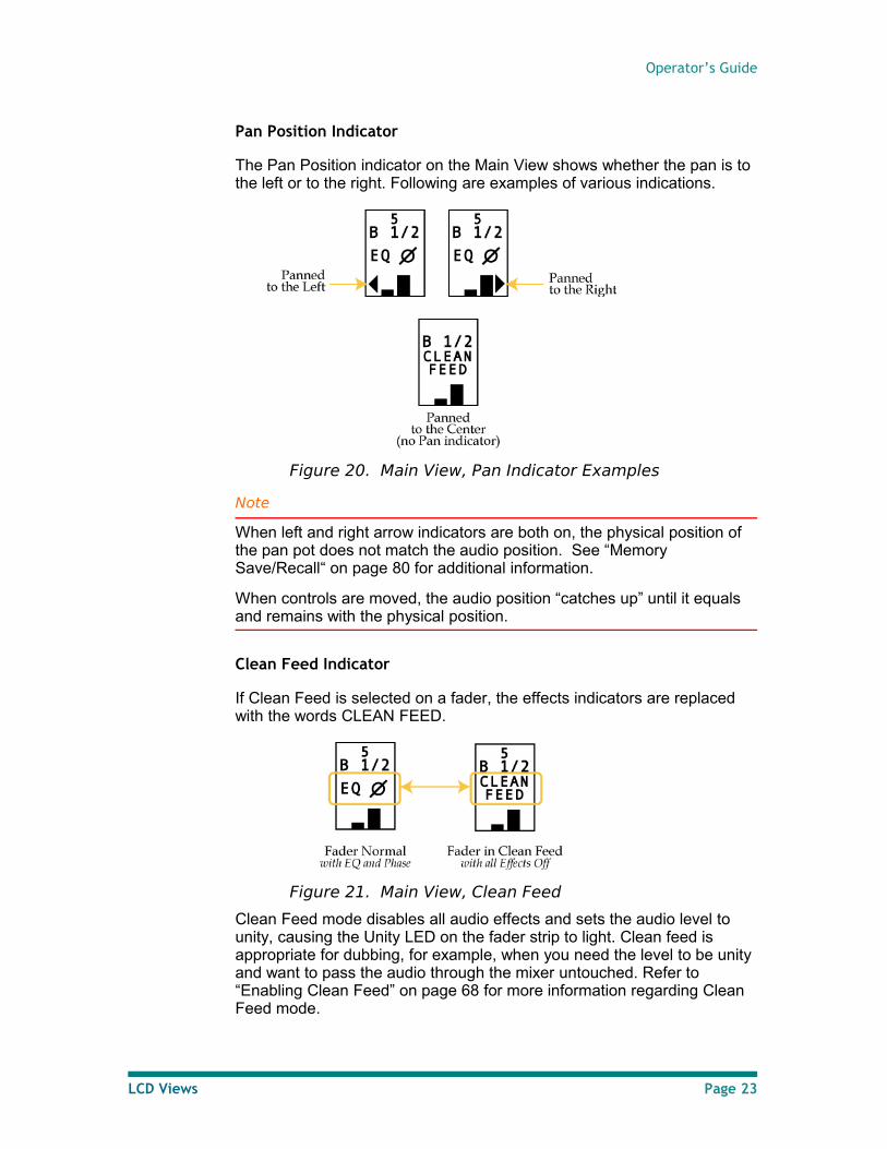
Pan Position Indicator
The Pan Position indicator on the Main View shows whether the pan is to the left or to the right. Following are examples of various indications.
Figure 20. Main View, Pan Indicator Examples
Note
When left and right arrow indicators are both on, the physical position of the pan pot does not match the audio position. See “Memory Save/Recall“ on page 80 for additional information.
When controls are moved, the audio position “catches up” until it equals and remains with the physical position.
Clean Feed Indicator
If Clean Feed is selected on a fader, the effects indicators are replaced with the words CLEAN FEED.
Figure 21. Main View, Clean Feed
Clean Feed mode disables all audio effects and sets the audio level to unity, causing the Unity LED on the fader strip to light. Clean feed is appropriate for dubbing, for example, when you need the level to be unity and want to pass the audio through the mixer untouched. Refer to “Enabling Clean Feed” on page 68 for more information regarding Clean Feed mode.
LCD Views Page 23
Renegade Labs Blue|328
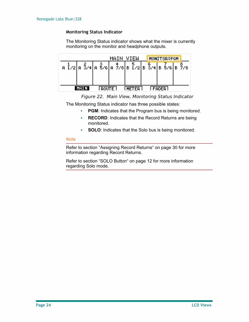
Monitoring Status Indicator
The Monitoring Status indicator shows what the mixer is currently monitoring on the monitor and headphone outputs.
Figure 22. Main View, Monitoring Status Indicator
The Monitoring Status indicator has three possible states:
• PGM: Indicates that the Program bus is being monitored.
• RECORD: Indicates that the Record Returns are being monitored.
• SOLO: Indicates that the Solo bus is being monitored.
Note
Refer to section “Assigning Record Returns“ on page 30 for more information regarding Record Returns.
Refer to section “SOLO Button“ on page 12 for more information regarding Solo mode.
Page 24 LCD Views
Operator’s Guide
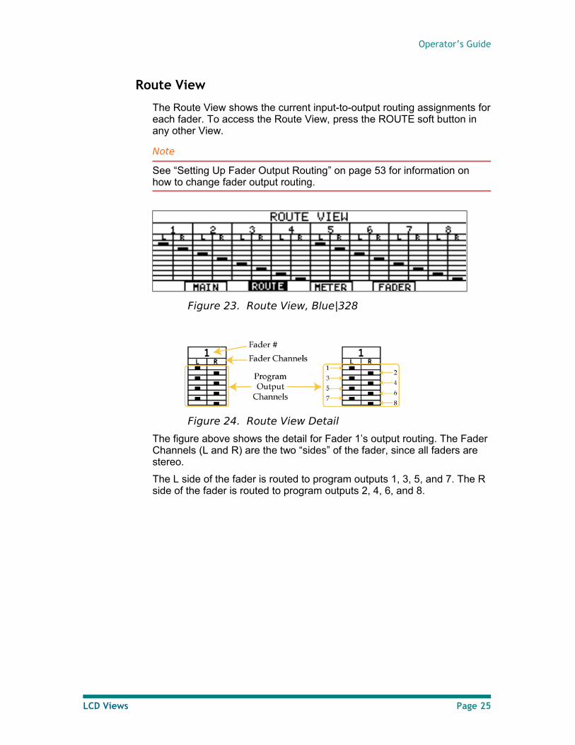
Route View
The Route View shows the current input-to-output routing assignments for each fader. To access the Route View, press the ROUTE soft button in any other View.
Note
See “Setting Up Fader Output Routing” on page 53 for information on how to change fader output routing.
Figure 23. Route View, Blue|328
Figure 24. Route View Detail
The figure above shows the detail for Fader 1’s output routing. The Fader Channels (L and R) are the two “sides” of the fader, since all faders are stereo.
The L side of the fader is routed to program outputs 1, 3, 5, and 7. The R side of the fader is routed to program outputs 2, 4, 6, and 8.
LCD Views Page 25
Renegade Labs Blue|328
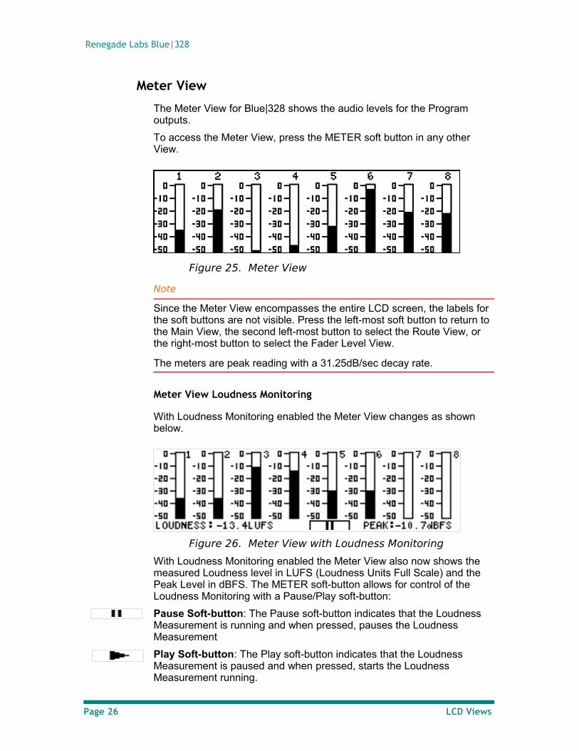
Meter View
The Meter View for Blue|328 shows the audio levels for the Program outputs.
To access the Meter View, press the METER soft button in any other View.
Figure 25. Meter View
Note
Since the Meter View encompasses the entire LCD screen, the labels for the soft buttons are not visible. Press the left-most soft button to return to the Main View, the second left-most button to select the Route View, or the right-most button to select the Fader Level View.
The meters are peak reading with a 31.25dB/sec decay rate.
Meter View Loudness Monitoring
With Loudness Monitoring enabled the Meter View changes as shown below.
Figure 26. Meter View with Loudness Monitoring
With Loudness Monitoring enabled the Meter View also now shows the measured Loudness level in LUFS (Loudness Units Full Scale) and the Peak Level in dBFS. The METER soft-button allows for control of the Loudness Monitoring with a Pause/Play soft-button:
Pause Soft-button: The Pause soft-button indicates that the Loudness Measurement is running and when pressed, pauses the Loudness Measurement
Play Soft-button: The Play soft-button indicates that the Loudness Measurement is paused and when pressed, starts the Loudness Measurement running.
Page 26 LCD Views
Operator’s Guide
Reset Loudness Monitoring: To reset the Loudness Monitoring press and hold the Play soft-button for 3 seconds.
Note
In order for Loudness Monitoring to appear on the Meter View it must first be enabled from the Loudness Menu. Refer to “Loudness Monitoring“ on page 47 for more information.
When analyzing the loudness of an audio segment make sure to stop the Loudness Monitoring with the Pause/Play soft-button so that the loudness algorithm can create the proper loudness measurement.
The Loudness Monitoring always follows the signals that are feeding the output meter that you see in the "Meter View”. Refer to “Blue|328 Audio Block Diagram“ on page 8 for more information.
LCD Views Page 27
Renegade Labs Blue|328
Fader Level View
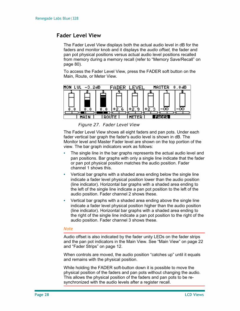
The Fader Level View displays both the actual audio level in dB for the faders and monitor knob and it displays the audio offset, the fader and pan pot physical positions versus actual audio level positions recalled from memory during a memory recall (refer to “Memory Save/Recall” on page 80).
To access the Fader Level View, press the FADER soft button on the Main, Route, or Meter View.
Figure 27. Fader Level View
The Fader Level View shows all eight faders and pan pots. Under each fader vertical bar graph the fader's audio level is shown in dB. The Monitor level and Master Fader level are shown on the top portion of the view. The bar graph indicators work as follows:
• The single line in the bar graphs represents the actual audio level and pan positions. Bar graphs with only a single line indicate that the fader or pan pot physical position matches the audio position. Fader channel 1 shows this.
• Vertical bar graphs with a shaded area ending below the single line indicate a fader level physical position lower than the audio position (line indicator). Horizontal bar graphs with a shaded area ending to the left of the single line indicate a pan pot position to the left of the audio position. Fader channel 2 shows these.
• Vertical bar graphs with a shaded area ending above the single line indicate a fader level physical position higher than the audio position (line indicator). Horizontal bar graphs with a shaded area ending to the right of the single line indicate a pan pot position to the right of the audio position. Fader channel 3 shows these.
Note
Audio offset is also indicated by the fader unity LEDs on the fader strips and the pan pot indicators in the Main View. See “Main View” on page 22 and “Fader Strips” on page 12.
When controls are moved, the audio position “catches up” until it equals and remains with the physical position.
While holding the FADER soft-button down it is possible to move the physical position of the faders and pan pots without changing the audio. This allows the physical position of the faders and pan pots to be re-synchronized with the audio levels after a register recall.
Page 28 LCD Views
Operator’s Guide
System Adjustments and Information Display
Overall system adjustments are made using the System Menus.
System Menu Tree
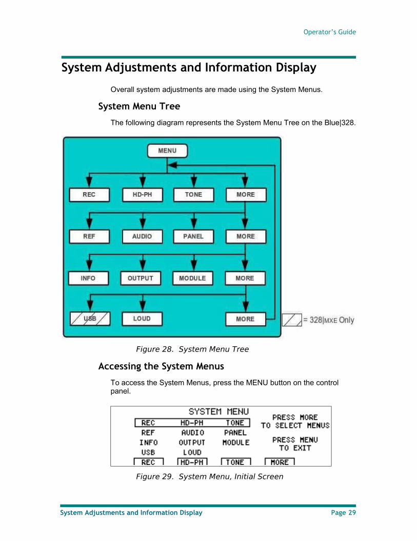
The following diagram represents the System Menu Tree on the Blue|328.
Figure 28. System Menu Tree
Accessing the System Menus
To access the System Menus, press the MENU button on the control panel.
Figure 29. System Menu, Initial Screen
System Adjustments and Information Display Page 29
Renegade Labs Blue|328
To access the next screen, which provides additional navigation via the soft labels at the bottom of the display, press the MORE soft button. The current selection of menus are highlighted with the rectangle.
As a general rule, while in the System Menu you can exit the menu and save your changes by simply pressing the control panel MENU button again.
Assigning Record Returns
Record returns are outputs of a recordable device after the results of mixing have been recorded. These can be monitored for quality assurance.
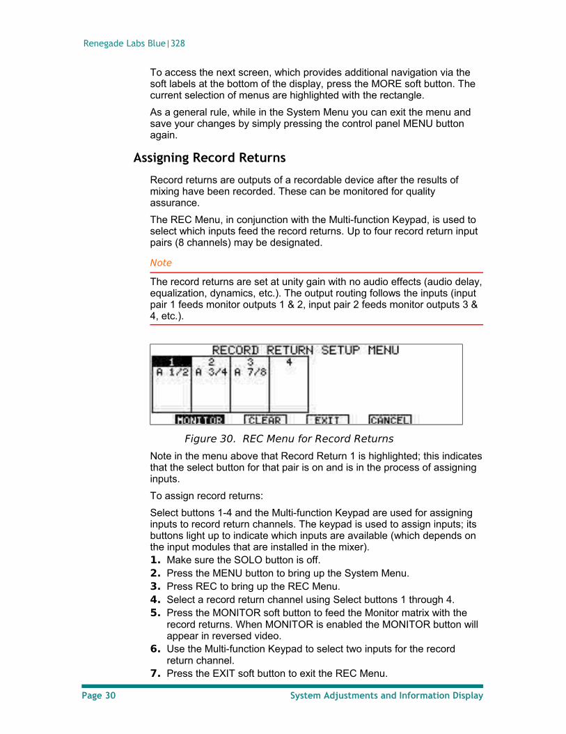
The REC Menu, in conjunction with the Multi-function Keypad, is used to select which inputs feed the record returns. Up to four record return input pairs (8 channels) may be designated.
Note
The record returns are set at unity gain with no audio effects (audio delay, equalization, dynamics, etc.). The output routing follows the inputs (input pair 1 feeds monitor outputs 1 & 2, input pair 2 feeds monitor outputs 3 & 4, etc.).
Figure 30. REC Menu for Record Returns
Note in the menu above that Record Return 1 is highlighted; this indicates that the select button for that pair is on and is in the process of assigning inputs.
To assign record returns:
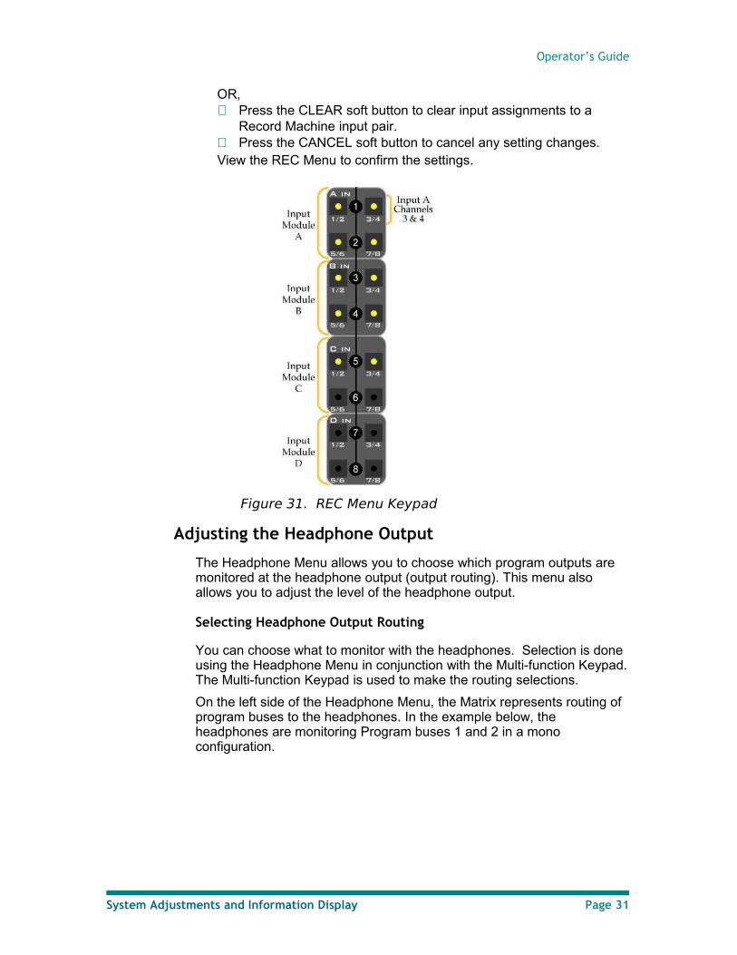
Select buttons 1-4 and the Multi-function Keypad are used for assigning inputs to record return channels. The keypad is used to assign inputs; its buttons light up to indicate which inputs are available (which depends on the input modules that are installed in the mixer).1. Make sure the SOLO button is off.2. Press the MENU button to bring up the System Menu.3. Press REC to bring up the REC Menu.4. Select a record return channel using Select buttons 1 through 4.5. Press the MONITOR soft button to feed the Monitor matrix with the
record returns. When MONITOR is enabled the MONITOR button will appear in reversed video.
6. Use the Multi-function Keypad to select two inputs for the record return channel.
7. Press the EXIT soft button to exit the REC Menu.
Page 30 System Adjustments and Information Display
Operator’s Guide
OR, Press the CLEAR soft button to clear input assignments to a
Record Machine input pair. Press the CANCEL soft button to cancel any setting changes. View the REC Menu to confirm the settings.
Figure 31. REC Menu Keypad
Adjusting the Headphone Output
The Headphone Menu allows you to choose which program outputs are monitored at the headphone output (output routing). This menu also allows you to adjust the level of the headphone output.
Selecting Headphone Output Routing
You can choose what to monitor with the headphones. Selection is done using the Headphone Menu in conjunction with the Multi-function Keypad. The Multi-function Keypad is used to make the routing selections.
On the left side of the Headphone Menu, the Matrix represents routing of program buses to the headphones. In the example below, the headphones are monitoring Program buses 1 and 2 in a mono configuration.
System Adjustments and Information Display Page 31
Renegade Labs Blue|328
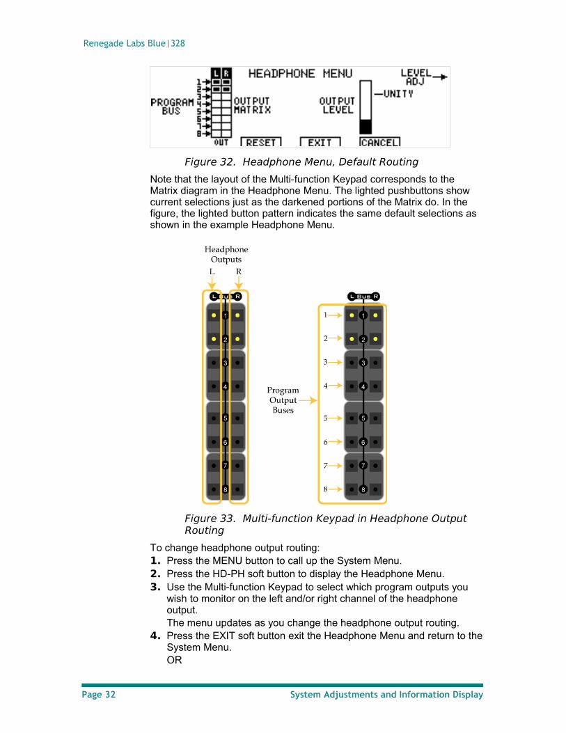
Figure 32. Headphone Menu, Default Routing
Note that the layout of the Multi-function Keypad corresponds to the Matrix diagram in the Headphone Menu. The lighted pushbuttons show current selections just as the darkened portions of the Matrix do. In the figure, the lighted button pattern indicates the same default selections as shown in the example Headphone Menu.
Figure 33. Multi-function Keypad in Headphone Output Routing
To change headphone output routing: 1. Press the MENU button to call up the System Menu. 2. Press the HD-PH soft button to display the Headphone Menu. 3. Use the Multi-function Keypad to select which program outputs you
wish to monitor on the left and/or right channel of the headphone output.The menu updates as you change the headphone output routing.
4. Press the EXIT soft button exit the Headphone Menu and return to the System Menu.OR
Page 32 System Adjustments and Information Display
Operator’s Guide
Press the CANCEL soft button to abort the operation. The headphone output matrix is not changed and returns to the previous settings. Press the RESET soft button to reset the crosspoints back to the default 2-channel configuration.
Adjusting the Headphone Output Level
To adjust the headphone output level: 1. Press the MENU button to display the System Menu.2. Press the HD-PH soft button to display the Headphone Menu. 3. Use the upper Soft Knob to set the desired level for the headphone
output. The Output Level display will change as you do so.Notice the Unity marker, which can be used as a guide when making the adjustment.
4. Press the EXIT soft button to exit the Headphone Menu and return to the System Menu.
Enable/Disable TONE
The TONE soft button will enable or disable TONE on the Program bus. When TONE is enabled the TONE button will appear in reverse video.
Note
When TONE is enabled any selection made to the Program bus will automatically disable TONE.
1. Press the MENU button to bring up the System Menu.2. Press TONE to enable or disable tone.
Selecting Reference Sync
Reference sync is the input to which the mixer is locked. The mixer can lock either to the AES audio input or the video input.
The mixer can lock to the following AES input rates: 48kHz, 96kHz, and 192kHz.
The mixer can lock to the following video formats:
Standard Definition (SD):
• NTSC (29.97 fps)
• PAL (25 fps)
High Definition (HD):
• 60Hz
• 59.94Hz 1080i
• 59.94Hz 720p
• 48Hz
• 48/1.001Hz
• 25 fps
• 24 fps
System Adjustments and Information Display Page 33
Renegade Labs Blue|328
• 24/1.001Hz
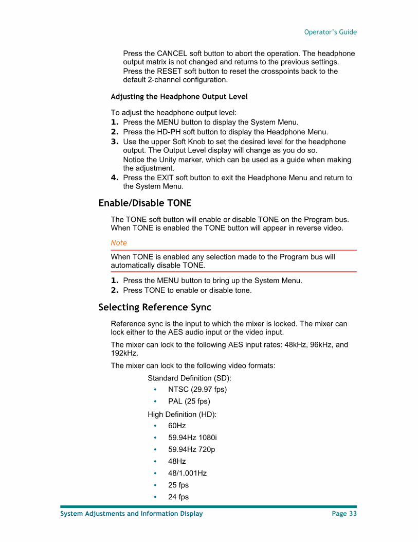
Reference sync is selected using the Sync Reference Menu:
Figure 34. Sync Reference Menu
To select a reference sync signal: 1. Press the MENU button to bring up the System Menu.2. Press the MORE button to bring up the second level of System Menu.3. Press the REF button to bring up the SYNC REFERENCE Menu.4. Press the corresponding soft button for the desired sync source.5. The selected source will highlight in the display, and the incoming rate
will be displayed. Lock Status indicates whether the mixer is able to lock to the selected sync source.
6. Press EXIT to exit the Sync Reference Menu and return to the System Menu.
Note
The preferred sync reference source is AES.
Making Digital Audio Adjustments
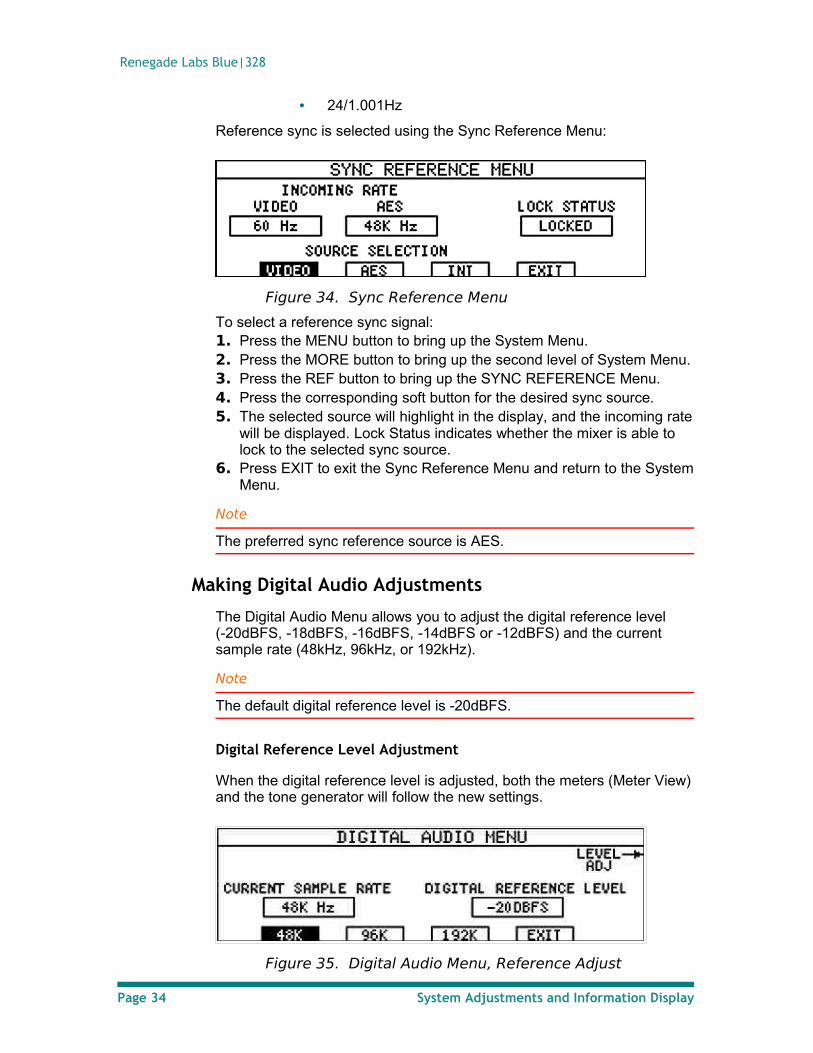
The Digital Audio Menu allows you to adjust the digital reference level (-20dBFS, -18dBFS, -16dBFS, -14dBFS or -12dBFS) and the current sample rate (48kHz, 96kHz, or 192kHz).
Note
The default digital reference level is -20dBFS.
Digital Reference Level Adjustment
When the digital reference level is adjusted, both the meters (Meter View) and the tone generator will follow the new settings.
Figure 35. Digital Audio Menu, Reference Adjust
Page 34 System Adjustments and Information Display
Operator’s Guide
To adjust the digital reference level: 1. Press the MENU button to bring up the System Menu.2. Press MORE to display the second level of the System Menu.3. Press the AUDIO button to bring up the DIGITAL AUDIO Menu.4. Use the Upper Soft Knob to adjust the digital reference level. The
level can be adjusted from -20dBFS to -12dBFS in 2dB steps. The Digital Reference Level box in the menu will change as you select different levels.
5. Press EXIT to accept the changes and return to the System Menu.
Sample Rate Requirements
The following audio effects require the indicated sample rate in order to function.
• EQ= 48kHz or 96kHz
• Dynamics=48kHz
Sample Rate Adjustment
The Digital Audio Menu is used to select an internal sample rate of 48kHz, 96kHz, or 192kHz.
Notes
If a Sample Rate Converter (SRC) AES Input Module is installed, the mixer will automatically up-sample or down-sample inputs with 32kHz-192kHz sample rates to match the mixer ’s internal sample rate.
If a non-SRC AES Input Module is installed, the input must match the mixer’s internal sample rate.
To change the internal sample rate: 1. Press the soft button corresponding to the desired sample rate.
The selected sample rate is displayed in the Current Sample Rate box of the Digital Audio Menu.
2. Press EXIT to accept the changes and return to the System Menu.
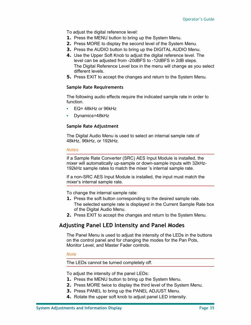
Adjusting Panel LED Intensity and Panel Modes
The Panel Menu is used to adjust the intensity of the LEDs in the buttons on the control panel and for changing the modes for the Pan Pots, Monitor Level, and Master Fader controls.
Note
The LEDs cannot be turned completely off.
To adjust the intensity of the panel LEDs:1. Press the MENU button to bring up the System Menu. 2. Press MORE twice to display the third level of the System Menu. 3. Press PANEL to bring up the PANEL ADJUST Menu. 4. Rotate the upper soft knob to adjust panel LED intensity.
System Adjustments and Information Display Page 35
Renegade Labs Blue|328
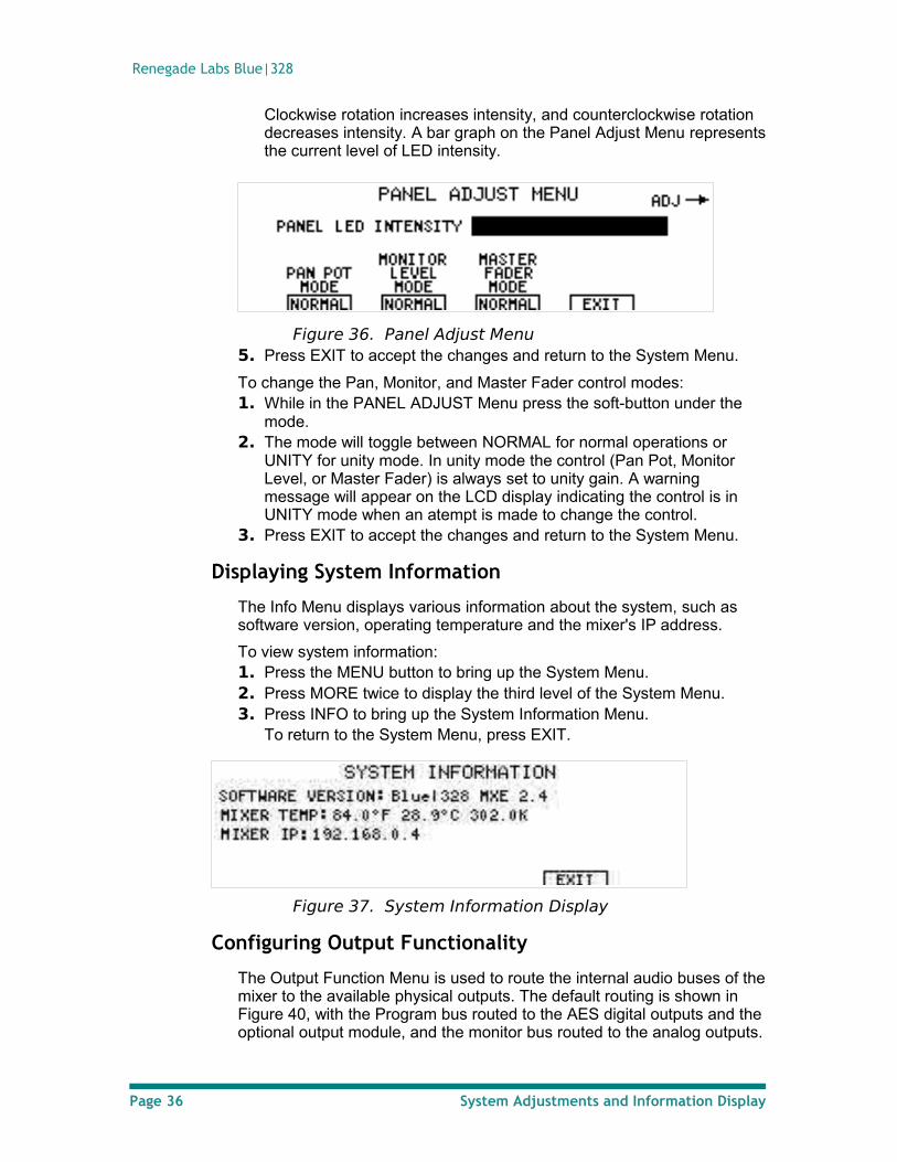
Clockwise rotation increases intensity, and counterclockwise rotation decreases intensity. A bar graph on the Panel Adjust Menu represents the current level of LED intensity.
Figure 36. Panel Adjust Menu5. Press EXIT to accept the changes and return to the System Menu.
To change the Pan, Monitor, and Master Fader control modes:1. While in the PANEL ADJUST Menu press the soft-button under the
mode.2. The mode will toggle between NORMAL for normal operations or
UNITY for unity mode. In unity mode the control (Pan Pot, Monitor Level, or Master Fader) is always set to unity gain. A warning message will appear on the LCD display indicating the control is in UNITY mode when an atempt is made to change the control.
3. Press EXIT to accept the changes and return to the System Menu.
Displaying System Information
The Info Menu displays various information about the system, such as software version, operating temperature and the mixer's IP address.
To view system information: 1. Press the MENU button to bring up the System Menu.2. Press MORE twice to display the third level of the System Menu.3. Press INFO to bring up the System Information Menu.
To return to the System Menu, press EXIT.
Figure 37. System Information Display
Configuring Output Functionality
The Output Function Menu is used to route the internal audio buses of the mixer to the available physical outputs. The default routing is shown in Figure 40, with the Program bus routed to the AES digital outputs and the optional output module, and the monitor bus routed to the analog outputs.
Page 36 System Adjustments and Information Display
Operator’s Guide
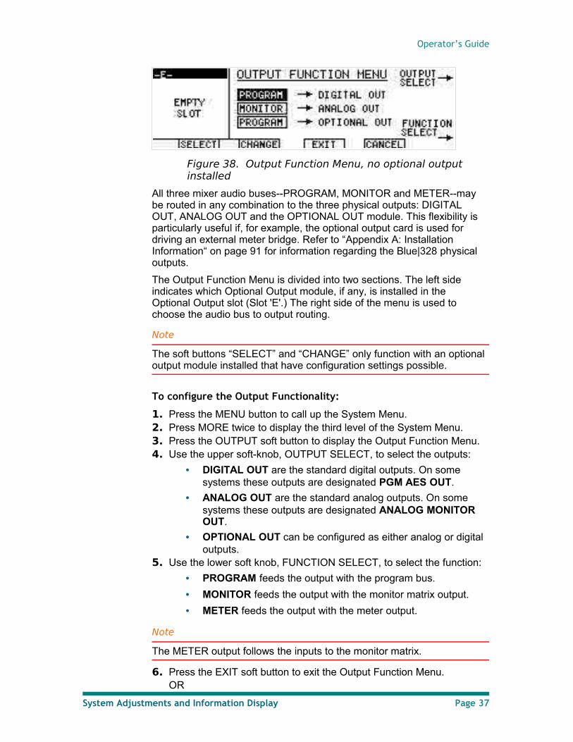
Figure 38. Output Function Menu, no optional output installed
All three mixer audio buses--PROGRAM, MONITOR and METER--may be routed in any combination to the three physical outputs: DIGITAL OUT, ANALOG OUT and the OPTIONAL OUT module. This flexibility is particularly useful if, for example, the optional output card is used for driving an external meter bridge. Refer to “Appendix A: Installation Information“ on page 91 for information regarding the Blue|328 physical outputs.
The Output Function Menu is divided into two sections. The left side indicates which Optional Output module, if any, is installed in the Optional Output slot (Slot 'E'.) The right side of the menu is used to choose the audio bus to output routing.
Note
The soft buttons “SELECT” and “CHANGE” only function with an optional output module installed that have configuration settings possible.
To configure the Output Functionality:
1. Press the MENU button to call up the System Menu.2. Press MORE twice to display the third level of the System Menu.3. Press the OUTPUT soft button to display the Output Function Menu.4. Use the upper soft-knob, OUTPUT SELECT, to select the outputs:
• DIGITAL OUT are the standard digital outputs. On some systems these outputs are designated PGM AES OUT.
• ANALOG OUT are the standard analog outputs. On some systems these outputs are designated ANALOG MONITOR OUT.
• OPTIONAL OUT can be configured as either analog or digital outputs.
5. Use the lower soft knob, FUNCTION SELECT, to select the function:
• PROGRAM feeds the output with the program bus.
• MONITOR feeds the output with the monitor matrix output.
• METER feeds the output with the meter output.
Note
The METER output follows the inputs to the monitor matrix.
6. Press the EXIT soft button to exit the Output Function Menu.OR
System Adjustments and Information Display Page 37
Renegade Labs Blue|328
Press the CANCEL soft button to abort the operation.
Note
Output function settings are not saved in the standard memory registers however, they are saved in non-volatile memory and will survive power cycles.
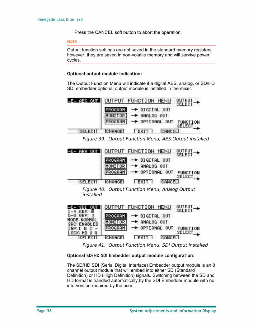
Optional output module indication:
The Output Function Menu will indicate if a digital AES, analog, or SD/HD SDI embedder optional output module is installed in the mixer.
Figure 39. Output Function Menu, AES Output installed
Figure 40. Output Function Menu, Analog Output installed
Figure 41. Output Function Menu, SDI Output installed
Optional SD/HD SDI Embedder output module configuration:
The SD/HD SDI (Serial Digital Interface) Embedder output module is an 8 channel output module that will embed into either SD (Standard Definition) or HD (High Definition) signals. Switching between the SD and HD format is handled automatically by the SDI Embedder module with no intervention required by the user.
Page 38 System Adjustments and Information Display
Operator’s Guide
Note
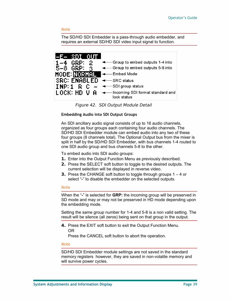
The SD/HD SDI Embedder is a pass-through audio embedder, and requires an external SD/HD SDI video input signal to function.
Figure 42. SDI Output Module Detail
Embedding Audio into SDI Output Groups
An SDI ancillary audio signal consists of up to 16 audio channels, organized as four groups each containing four audio channels. The SD/HD SDI Embedder module can embed audio into any two of these four groups (8 channels total). The Optional Output bus from the mixer is split in half by the SD/HD SDI Embedder, with bus channels 1-4 routed to one SDI audio group and bus channels 5-8 to the other.
To embed audio into SDI audio groups:1. Enter into the Output Function Menu as previously described.2. Press the SELECT soft button to toggle to the desired outputs. The
current selection will be displayed in reverse video.3. Press the CHANGE soft button to toggle through groups 1 – 4 or
select “-” to disable the embedder on the selected outputs.
Note
When the “-” is selected for GRP: the incoming group will be preserved in SD mode and may or may not be preserved in HD mode depending upon the embedding mode.
Setting the same group number for 1-4 and 5-8 is a non valid setting. The result will be silence (all zeros) being sent on that group in the output.
4. Press the EXIT soft button to exit the Output Function Menu.OR Press the CANCEL soft button to abort the operation.
Note
SD/HD SDI Embedder module settings are not saved in the standard memory registers however, they are saved in non-volatile memory and will survive power cycles.
System Adjustments and Information Display Page 39
Renegade Labs Blue|328
Adjusting SDI HD Embed Mode
The HD Embed Mode control is used to switch between NORMAL and REPLACE modes for the selected groups to be embedded into. For both NORMAL and REPLACE modes the SD/HD SDI Embedder module will automatically switch between replace and cascade operation on the selected group(s). Replace is used when the selected audio group is already present in the SDI signal at which time it is replaced with a new audio group. Cascade is used when the selected audio group is not present at which time a new audio group is cascaded into the selected group and all other audio groups are preserved and passed through.
NORMAL mode: When replacing an audio group only the selected group(s) are replaced and all other groups are always preserved and passed through.
REPLACE mode: When replacing any audio group all other existing audio groups will be strip out.
Note
When embedding audio in SD video, the operations is the same as HD NORMAL mode in that when replacing an audio group(s) only the selected group(s) are replaced and all other groups are always preserved and passed through.
To adjust the SDI output Embed Mode:1. Enter into the Output Function Menu as previously described.2. Press the SELECT soft button to toggle to the MODE. The NORMAL
or REPLACE will be highlighted to indicate that it is selected.3. Press the CHANGE soft button to change modes.4. Press the EXIT soft button to exit the Output Function Menu.
OR Press the CANCEL soft button to abort the operation.
Adjusting SDI Output SRC Controls
The Sample Rate Converter (SRC) control is used to bypass or enable the SRC on the SDI output module.
BYPASS indicates that the SRC is not in the audio path. This is the default setting. Bypass mode is used when the Blue|328 is running at a 48kHz sample rate and locked to the same house sync as the incoming SDI signal.
ENABLED indicates that the SRC is in the audio path. Any mis-match or slip between the embedded audio sample rate and the Blue|328 master clock is compensated for with the SRC. This mode is used when the Blue|328 is running at the 96kHz or 192kKHz sample rate or when the input video and the Blue|328 are not locked to the same house sync.
To adjust the SDI output module SRC:1. Enter into the Output Function Menu as previously described.2. Press the SELECT soft button to toggle to the SRC. The BYPASS or
ENABLE will be highlighted to indicate that it is selected.
Page 40 System Adjustments and Information Display
Operator’s Guide
3. Press the CHANGE soft button to toggle between BYPASS and ENABLE.
4. Press the EXIT soft button to exit the Output Function Menu.OR Press the CANCEL soft button to abort the operation.
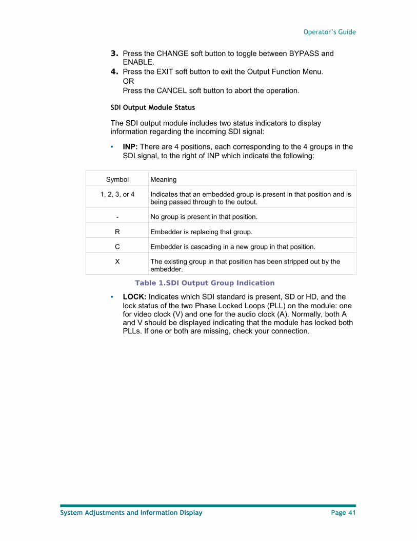
SDI Output Module Status
The SDI output module includes two status indicators to display information regarding the incoming SDI signal:
• INP: There are 4 positions, each corresponding to the 4 groups in the SDI signal, to the right of INP which indicate the following:
Symbol Meaning
1, 2, 3, or 4 Indicates that an embedded group is present in that position and is being passed through to the output.
- No group is present in that position.
R Embedder is replacing that group.
C Embedder is cascading in a new group in that position.
X The existing group in that position has been stripped out by the embedder.
Table 1.SDI Output Group Indication
• LOCK: Indicates which SDI standard is present, SD or HD, and the lock status of the two Phase Locked Loops (PLL) on the module: one for video clock (V) and one for the audio clock (A). Normally, both A and V should be displayed indicating that the module has locked both PLLs. If one or both are missing, check your connection.
System Adjustments and Information Display Page 41
Renegade Labs Blue|328
View and Adjusting Module Parameters
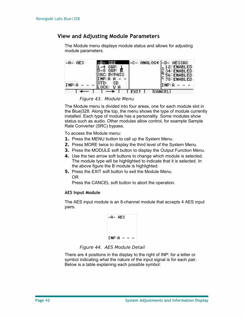
The Module menu displays module status and allows for adjusting module parameters.
Figure 43. Module Menu
The Module menu is divided into four areas, one for each module slot in the Blue|328. Along the top, the menu shows the type of module currently installed. Each type of module has a personality. Some modules show status such as audio. Other modules allow control, for example Sample Rate Converter (SRC) bypass.
To access the Module menu:1. Press the MENU button to call up the System Menu.2. Press MORE twice to display the third level of the System Menu.3. Press the MODULE soft button to display the Output Function Menu.4. Use the two arrow soft buttons to change which module is selected.
The module type will be highlighted to indicate that it is selected. In the above figure the B module is highlighted.
5. Press the EXIT soft button to exit the Module Menu.OR Press the CANCEL soft button to abort the operation.
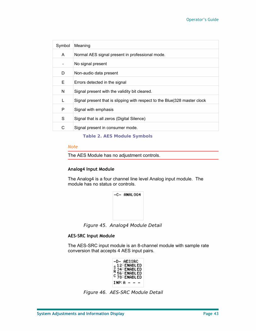
AES Input Module
The AES input module is an 8-channel module that accepts 4 AES input pairs.
Figure 44. AES Module Detail
There are 4 positions in the display to the right of INP: for a letter or symbol indicating what the nature of the input signal is for each pair. Below is a table explaining each possible symbol:
Page 42 System Adjustments and Information Display
Operator’s Guide
Symbol Meaning
A Normal AES signal present in professional mode.
- No signal present
D Non-audio data present
E Errors detected in the signal
N Signal present with the validity bit cleared.
L Signal present that is slipping with respect to the Blue|328 master clock
P Signal with emphasis
S Signal that is all zeros (Digital Silence)
C Signal present in consumer mode.
Table 2. AES Module Symbols
Note
The AES Module has no adjustment controls.
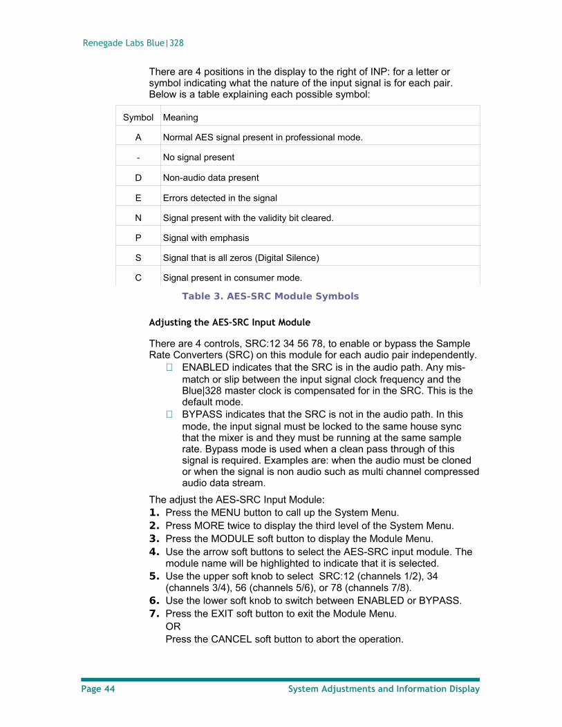
Analog4 Input Module
The Analog4 is a four channel line level Analog input module. The module has no status or controls.
Figure 45. Analog4 Module Detail
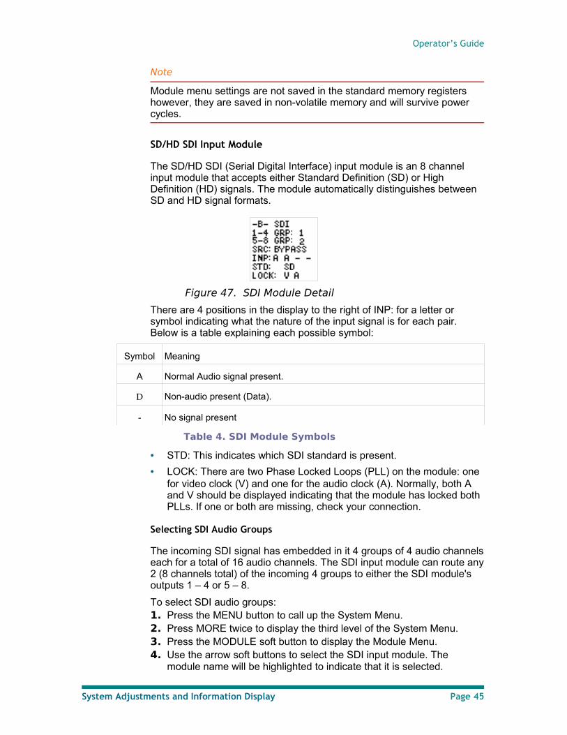
AES-SRC Input Module
The AES-SRC input module is an 8-channel module with sample rate conversion that accepts 4 AES input pairs.
Figure 46. AES-SRC Module Detail
System Adjustments and Information Display Page 43
Renegade Labs Blue|328
There are 4 positions in the display to the right of INP: for a letter or symbol indicating what the nature of the input signal is for each pair. Below is a table explaining each possible symbol:
Symbol Meaning
A Normal AES signal present in professional mode.
- No signal present
D Non-audio data present
E Errors detected in the signal
N Signal present with the validity bit cleared.
P Signal with emphasis
S Signal that is all zeros (Digital Silence)
C Signal present in consumer mode.
Table 3. AES-SRC Module Symbols
Adjusting the AES-SRC Input Module
There are 4 controls, SRC:12 34 56 78, to enable or bypass the Sample Rate Converters (SRC) on this module for each audio pair independently.
ENABLED indicates that the SRC is in the audio path. Any mis-match or slip between the input signal clock frequency and the Blue|328 master clock is compensated for in the SRC. This is the default mode.
BYPASS indicates that the SRC is not in the audio path. In this mode, the input signal must be locked to the same house sync that the mixer is and they must be running at the same sample rate. Bypass mode is used when a clean pass through of this signal is required. Examples are: when the audio must be cloned or when the signal is non audio such as multi channel compressed audio data stream.
The adjust the AES-SRC Input Module:1. Press the MENU button to call up the System Menu.2. Press MORE twice to display the third level of the System Menu.3. Press the MODULE soft button to display the Module Menu.4. Use the arrow soft buttons to select the AES-SRC input module. The
module name will be highlighted to indicate that it is selected.5. Use the upper soft knob to select SRC:12 (channels 1/2), 34
(channels 3/4), 56 (channels 5/6), or 78 (channels 7/8).6. Use the lower soft knob to switch between ENABLED or BYPASS.7. Press the EXIT soft button to exit the Module Menu.
OR Press the CANCEL soft button to abort the operation.
Page 44 System Adjustments and Information Display
Operator’s Guide
Note
Module menu settings are not saved in the standard memory registers however, they are saved in non-volatile memory and will survive power cycles.
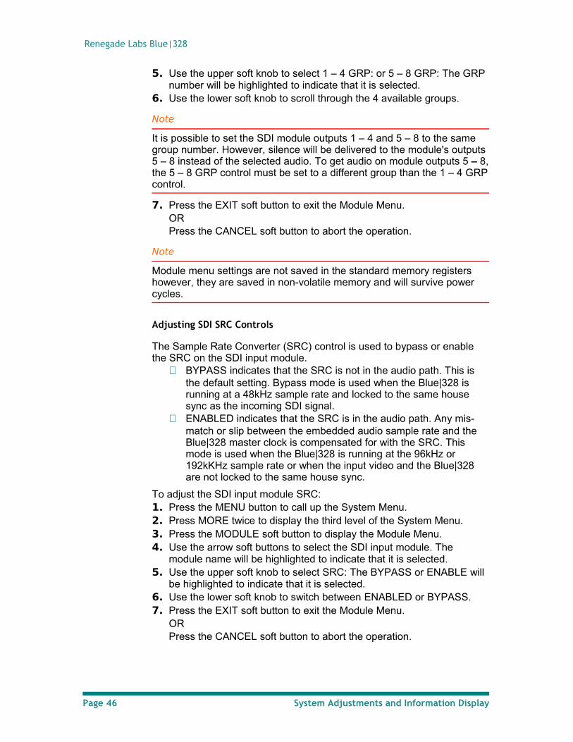
SD/HD SDI Input Module
The SD/HD SDI (Serial Digital Interface) input module is an 8 channel input module that accepts either Standard Definition (SD) or High Definition (HD) signals. The module automatically distinguishes between SD and HD signal formats.
Figure 47. SDI Module Detail
There are 4 positions in the display to the right of INP: for a letter or symbol indicating what the nature of the input signal is for each pair. Below is a table explaining each possible symbol:
Symbol Meaning
A Normal Audio signal present.
D Non-audio present (Data).
- No signal present
Table 4. SDI Module Symbols
• STD: This indicates which SDI standard is present.
• LOCK: There are two Phase Locked Loops (PLL) on the module: one for video clock (V) and one for the audio clock (A). Normally, both A and V should be displayed indicating that the module has locked both PLLs. If one or both are missing, check your connection.
Selecting SDI Audio Groups
The incoming SDI signal has embedded in it 4 groups of 4 audio channels each for a total of 16 audio channels. The SDI input module can route any 2 (8 channels total) of the incoming 4 groups to either the SDI module's outputs 1 – 4 or 5 – 8.
To select SDI audio groups:1. Press the MENU button to call up the System Menu.2. Press MORE twice to display the third level of the System Menu.3. Press the MODULE soft button to display the Module Menu.4. Use the arrow soft buttons to select the SDI input module. The
module name will be highlighted to indicate that it is selected.
System Adjustments and Information Display Page 45
Renegade Labs Blue|328
5. Use the upper soft knob to select 1 – 4 GRP: or 5 – 8 GRP: The GRP number will be highlighted to indicate that it is selected.
6. Use the lower soft knob to scroll through the 4 available groups.
Note
It is possible to set the SDI module outputs 1 – 4 and 5 – 8 to the same group number. However, silence will be delivered to the module's outputs 5 – 8 instead of the selected audio. To get audio on module outputs 5 – 8, the 5 – 8 GRP control must be set to a different group than the 1 – 4 GRP control.
7. Press the EXIT soft button to exit the Module Menu.OR Press the CANCEL soft button to abort the operation.
Note
Module menu settings are not saved in the standard memory registers however, they are saved in non-volatile memory and will survive power cycles.
Adjusting SDI SRC Controls
The Sample Rate Converter (SRC) control is used to bypass or enable the SRC on the SDI input module.
BYPASS indicates that the SRC is not in the audio path. This is the default setting. Bypass mode is used when the Blue|328 is running at a 48kHz sample rate and locked to the same house sync as the incoming SDI signal.
ENABLED indicates that the SRC is in the audio path. Any mis-match or slip between the embedded audio sample rate and the Blue|328 master clock is compensated for with the SRC. This mode is used when the Blue|328 is running at the 96kHz or 192kKHz sample rate or when the input video and the Blue|328 are not locked to the same house sync.
To adjust the SDI input module SRC:1. Press the MENU button to call up the System Menu.2. Press MORE twice to display the third level of the System Menu.3. Press the MODULE soft button to display the Module Menu.4. Use the arrow soft buttons to select the SDI input module. The
module name will be highlighted to indicate that it is selected.5. Use the upper soft knob to select SRC: The BYPASS or ENABLE will
be highlighted to indicate that it is selected.6. Use the lower soft knob to switch between ENABLED or BYPASS.7. Press the EXIT soft button to exit the Module Menu.
OR Press the CANCEL soft button to abort the operation.
Page 46 System Adjustments and Information Display
Operator’s Guide
Note
Module menu settings are not saved in the standard memory registers however, they are saved in non-volatile memory and will survive power cycles.
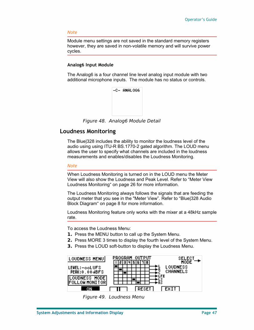
Analog6 Input Module
The Analog6 is a four channel line level analog input module with two additional microphone inputs. The module has no status or controls.
Figure 48. Analog6 Module Detail
Loudness Monitoring
The Blue|328 includes the ability to monitor the loudness level of the audio using using ITU-R BS.1770-2 gated algorithm. The LOUD menu allows the user to specify what channels are included in the loudness measurements and enables/disables the Loudness Monitoring.
Note
When Loudness Monitoring is turned on in the LOUD menu the Meter View will also show the Loudness and Peak Level. Refer to “Meter View Loudness Monitoring“ on page 26 for more information.
The Loudness Monitoring always follows the signals that are feeding the output meter that you see in the "Meter View”. Refer to “Blue|328 Audio Block Diagram“ on page 8 for more information.
Loudness Monitoring feature only works with the mixer at a 48kHz sample rate.
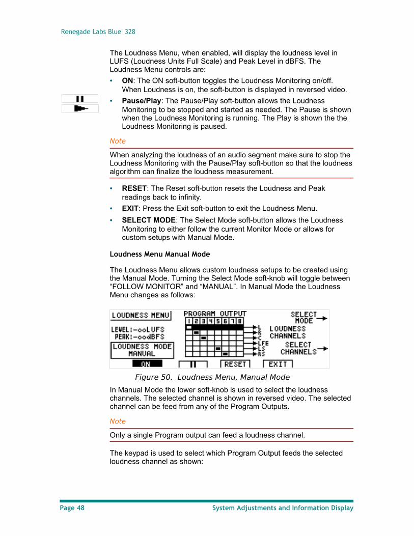
To access the Loudness Menu:1. Press the MENU button to call up the System Menu.2. Press MORE 3 times to display the fourth level of the System Menu.3. Press the LOUD soft-button to display the Loudness Menu.
Figure 49. Loudness Menu
System Adjustments and Information Display Page 47
Renegade Labs Blue|328
The Loudness Menu, when enabled, will display the loudness level in LUFS (Loudness Units Full Scale) and Peak Level in dBFS. The Loudness Menu controls are:
• ON: The ON soft-button toggles the Loudness Monitoring on/off. When Loudness is on, the soft-button is displayed in reversed video.
• Pause/Play: The Pause/Play soft-button allows the Loudness Monitoring to be stopped and started as needed. The Pause is shown when the Loudness Monitoring is running. The Play is shown the the Loudness Monitoring is paused.
Note
When analyzing the loudness of an audio segment make sure to stop the Loudness Monitoring with the Pause/Play soft-button so that the loudness algorithm can finalize the loudness measurement.
• RESET: The Reset soft-button resets the Loudness and Peak readings back to infinity.
• EXIT: Press the Exit soft-button to exit the Loudness Menu.
• SELECT MODE: The Select Mode soft-button allows the Loudness Monitoring to either follow the current Monitor Mode or allows for custom setups with Manual Mode.
Loudness Menu Manual Mode
The Loudness Menu allows custom loudness setups to be created using the Manual Mode. Turning the Select Mode soft-knob will toggle between “FOLLOW MONITOR” and “MANUAL”. In Manual Mode the Loudness Menu changes as follows:
Figure 50. Loudness Menu, Manual Mode
In Manual Mode the lower soft-knob is used to select the loudness channels. The selected channel is shown in reversed video. The selected channel can be feed from any of the Program Outputs.
Note
Only a single Program output can feed a loudness channel.
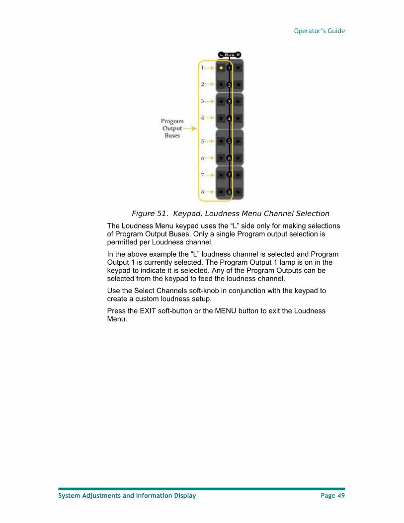
The keypad is used to select which Program Output feeds the selected loudness channel as shown:
Page 48 System Adjustments and Information Display
Operator’s Guide
Figure 51. Keypad, Loudness Menu Channel Selection
The Loudness Menu keypad uses the “L” side only for making selections of Program Output Buses. Only a single Program output selection is permitted per Loudness channel.
In the above example the “L” loudness channel is selected and Program Output 1 is currently selected. The Program Output 1 lamp is on in the keypad to indicate it is selected. Any of the Program Outputs can be selected from the keypad to feed the loudness channel.
Use the Select Channels soft-knob in conjunction with the keypad to create a custom loudness setup.
Press the EXIT soft-button or the MENU button to exit the Loudness Menu.
System Adjustments and Information Display Page 49
Renegade Labs Blue|328
Making Fader Assignments
This section describes the steps involved in assigning a stereo input pair to a fader. Remember, all input faders on the mixer are stereo, but you can assign just one input channel to any fader, if need be.
Note
This operation is different depending on whether the selected fader already has inputs assigned. If a fader already has an input assigned to it, the Route Menu is displayed first and you must press ASSIGN to go to the Fader Assignment Menu.
Making Fader Input Assignments
In the example used in these instructions, input slots A and B each have 8-channel input modules, slot C has a 4-channel input module, and slot D has no input module installed.
When assigning inputs to a fader, you can choose to preview the inputs to locate the proper input before making the assignment. See the instructions.
Note
Only one fader can be assigned at a time. If you have selected a fader for input assignment and then select a different fader, the original fader is deselected.
If you deselect the Select button during the assignment operation (without selecting an input), the assignment operation is aborted.
Faders can re-use inputs. In other words, two faders can use the same input channels.
Assigning inputs to a fader
This procedure describes how to assign a stereo input pair to a fader.1. Press the Select button for the desired fader. The Select button's LED
lights up.
Note
Always make sure the SOLO button is turned off when using the Select buttons for Fader Assignments.
Page 50 Making Fader Assignments
Operator’s Guide
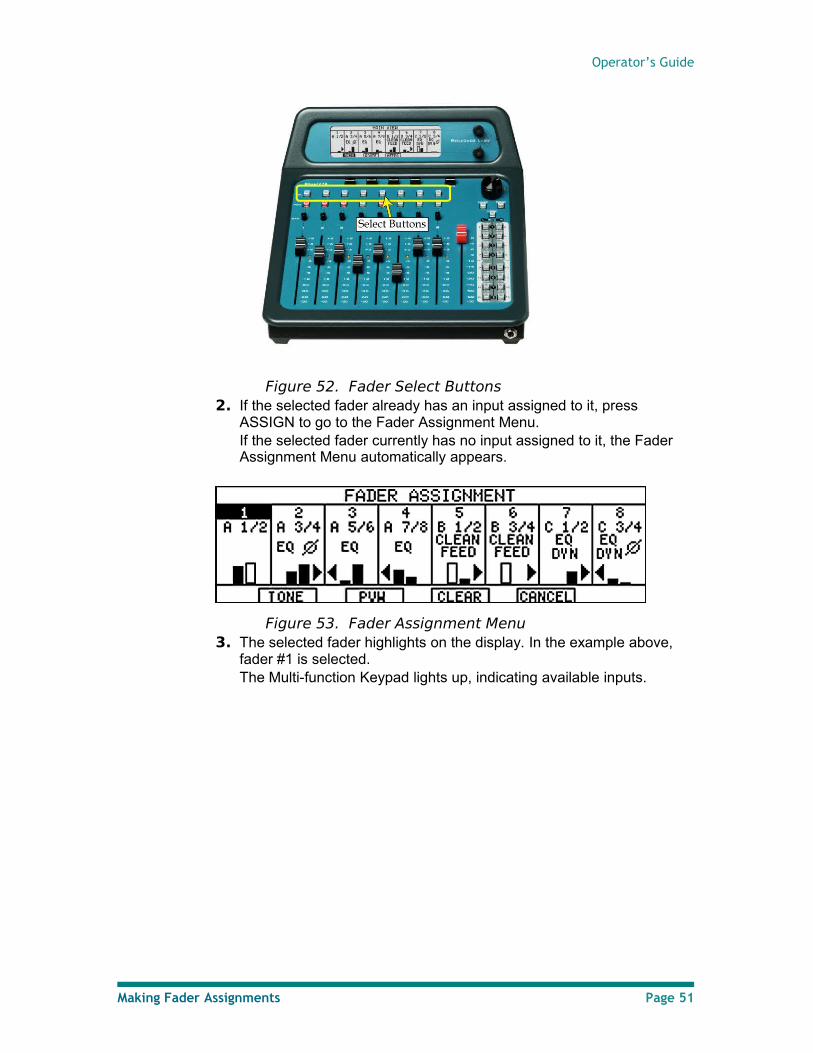
Figure 52. Fader Select Buttons2. If the selected fader already has an input assigned to it, press
ASSIGN to go to the Fader Assignment Menu. If the selected fader currently has no input assigned to it, the Fader Assignment Menu automatically appears.
Figure 53. Fader Assignment Menu3. The selected fader highlights on the display. In the example above,
fader #1 is selected.The Multi-function Keypad lights up, indicating available inputs.
Making Fader Assignments Page 51
Renegade Labs Blue|328
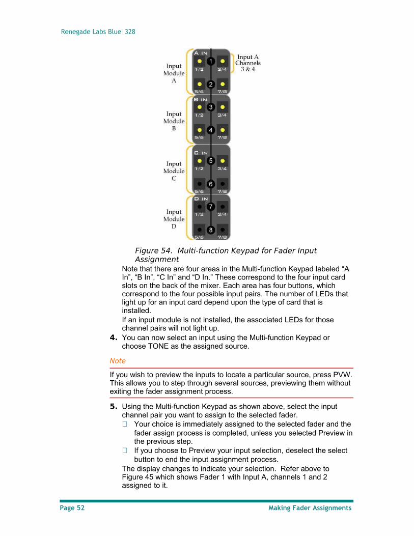
Figure 54. Multi-function Keypad for Fader Input Assignment
Note that there are four areas in the Multi-function Keypad labeled “A In”, “B In”, “C In” and “D In.” These correspond to the four input card slots on the back of the mixer. Each area has four buttons, which correspond to the four possible input pairs. The number of LEDs that light up for an input card depend upon the type of card that is installed. If an input module is not installed, the associated LEDs for those channel pairs will not light up.
4. You can now select an input using the Multi-function Keypad or choose TONE as the assigned source.
Note
If you wish to preview the inputs to locate a particular source, press PVW. This allows you to step through several sources, previewing them without exiting the fader assignment process.
5. Using the Multi-function Keypad as shown above, select the input channel pair you want to assign to the selected fader. Your choice is immediately assigned to the selected fader and the
fader assign process is completed, unless you selected Preview in the previous step.
If you choose to Preview your input selection, deselect the select button to end the input assignment process.
The display changes to indicate your selection. Refer above to Figure 45 which shows Fader 1 with Input A, channels 1 and 2 assigned to it.
Page 52 Making Fader Assignments
Operator’s Guide
Clearing an input assigned to a fader
1. Press the Select button for the desired fader. 2. Press ASSIGN to display the Fader Assignment Menu 3. Choose CLEAR to clear the input. 4. Deselect the Select button to end the fader de-assignment process.
Setting Up Fader Output Routing
Output routing is the process of choosing which Program output buses a fader’s stereo output will be routed to when the PGM button for the fader is selected.
To change a fader’s output routing: 1. Press the Select button above the desired fader to display the Route
Menu.
Note
If the selected fader has no inputs assigned to it, you will be taken to the Fader Assignment Menu for input assignment. The fader must have an input assigned to it in order to perform output routing. See “Assigning inputs to a fader” on page 50 for more information.
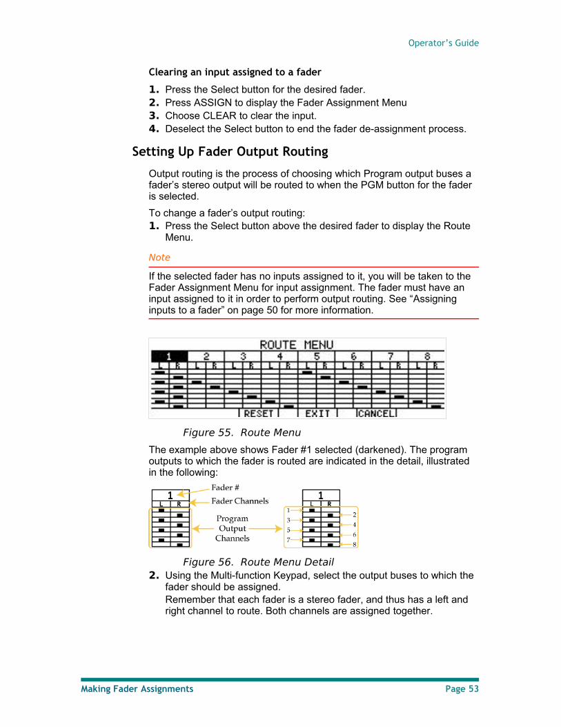
Figure 55. Route Menu
The example above shows Fader #1 selected (darkened). The program outputs to which the fader is routed are indicated in the detail, illustrated in the following:
Figure 56. Route Menu Detail2. Using the Multi-function Keypad, select the output buses to which the
fader should be assigned.Remember that each fader is a stereo fader, and thus has a left and right channel to route. Both channels are assigned together.
Making Fader Assignments Page 53
Renegade Labs Blue|328
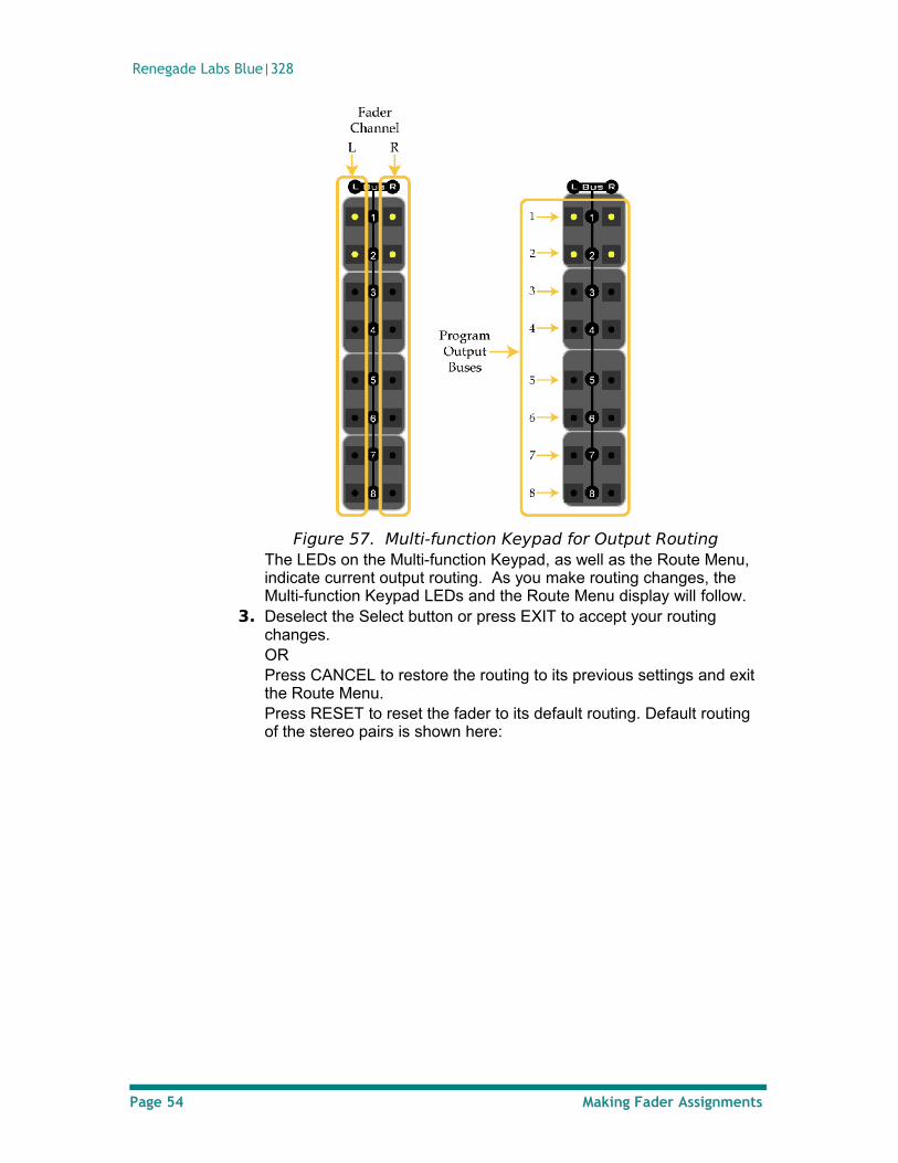
Figure 57. Multi-function Keypad for Output RoutingThe LEDs on the Multi-function Keypad, as well as the Route Menu, indicate current output routing. As you make routing changes, the Multi-function Keypad LEDs and the Route Menu display will follow.
3. Deselect the Select button or press EXIT to accept your routing changes. ORPress CANCEL to restore the routing to its previous settings and exit the Route Menu.Press RESET to reset the fader to its default routing. Default routing of the stereo pairs is shown here:
Page 54 Making Fader Assignments
Operator’s Guide
Fader # Default Output Routing
1 1 / 2
2 3 / 4
3 5 / 6
4 7 / 8
5 1 / 2
6 3 / 4
7 5 / 6
8 7 / 8
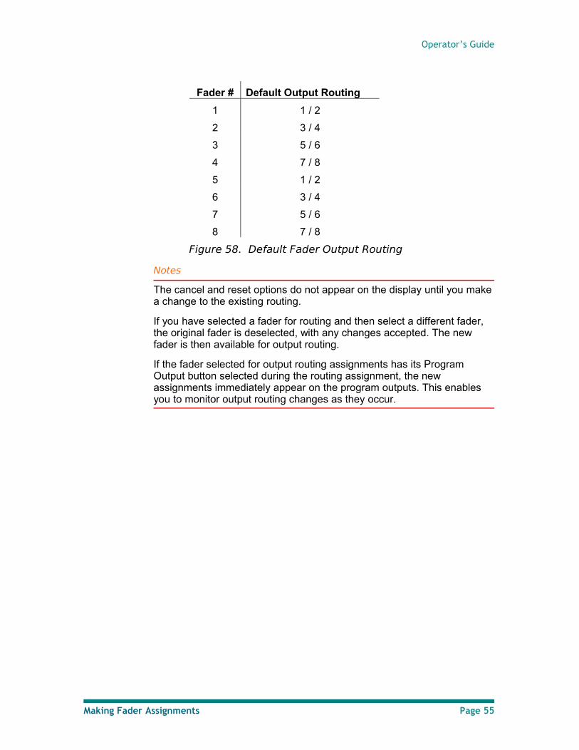
Figure 58. Default Fader Output Routing
Notes
The cancel and reset options do not appear on the display until you make a change to the existing routing.
If you have selected a fader for routing and then select a different fader, the original fader is deselected, with any changes accepted. The new fader is then available for output routing.
If the fader selected for output routing assignments has its Program Output button selected during the routing assignment, the new assignments immediately appear on the program outputs. This enables you to monitor output routing changes as they occur.
Making Fader Assignments Page 55
Renegade Labs Blue|328
Applying Audio Effects
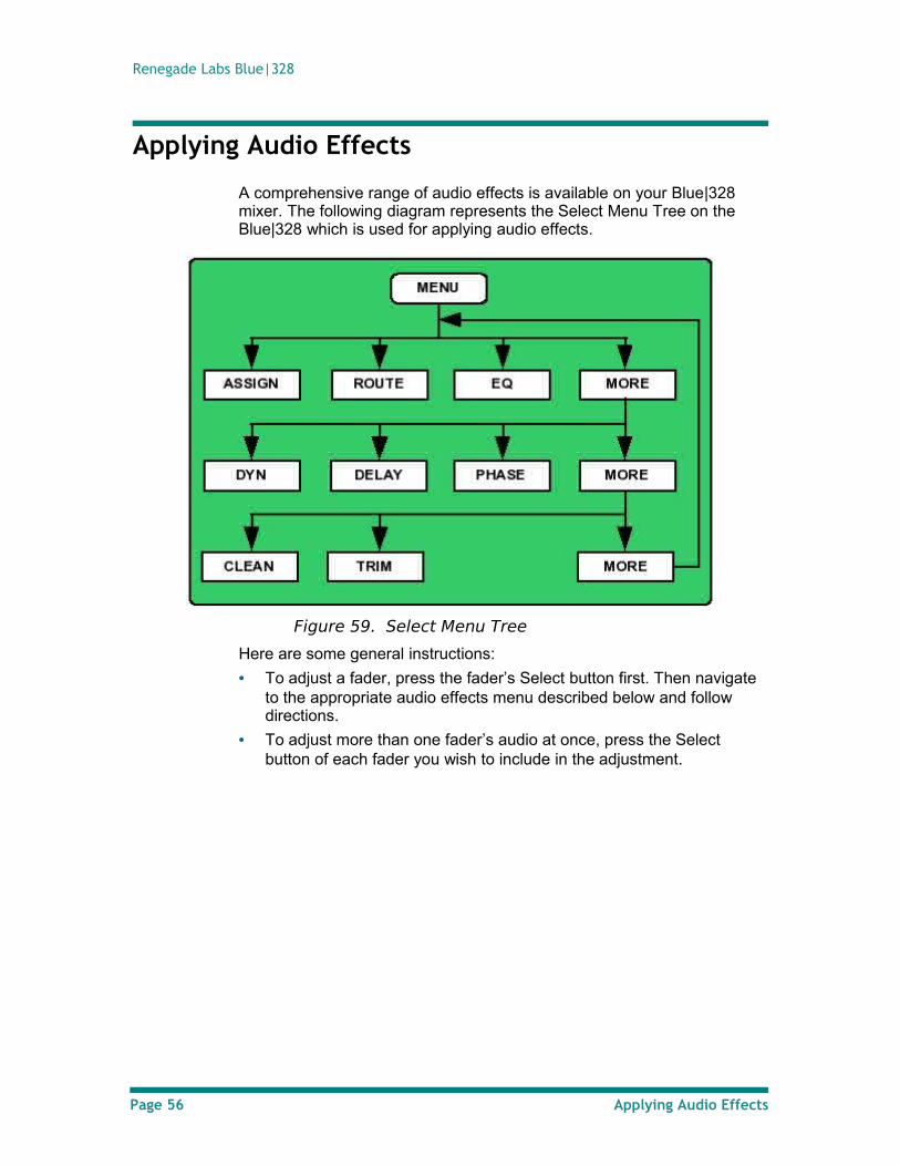
A comprehensive range of audio effects is available on your Blue|328 mixer. The following diagram represents the Select Menu Tree on the Blue|328 which is used for applying audio effects.
Figure 59. Select Menu Tree
Here are some general instructions:
• To adjust a fader, press the fader’s Select button first. Then navigate to the appropriate audio effects menu described below and follow directions.
• To adjust more than one fader’s audio at once, press the Select button of each fader you wish to include in the adjustment.
Page 56 Applying Audio Effects
Operator’s Guide
Applying Equalization
The Blue|328 provides you with excellent equalization (EQ) controls. You can adjust any or all inputs via the 3-band (low, mid, high) equalizer. These parameters are variable with several choices of Q (width) adjustment as well. The display provides immediate visual feedback as you make adjustments.
You can also make equalization adjustments for more than one fader at a time.
Available Equalization Parameters
Following is a list of equalization parameters and the soft labels associated with them:
Parameter Label Range or Setting
Low Band L-BAND 20Hz to 1kHz
Mid Band M-BAND 100Hz to 10kHz
High Band H-BAND 1kHz to 20kHz
Low Q LOW-Q Q = 0.7
High Q HI-Q Q = 2
Notch NOTCH Q = 5
Gain GAIN Low & High Q:+/- 12dB Notch: -∞
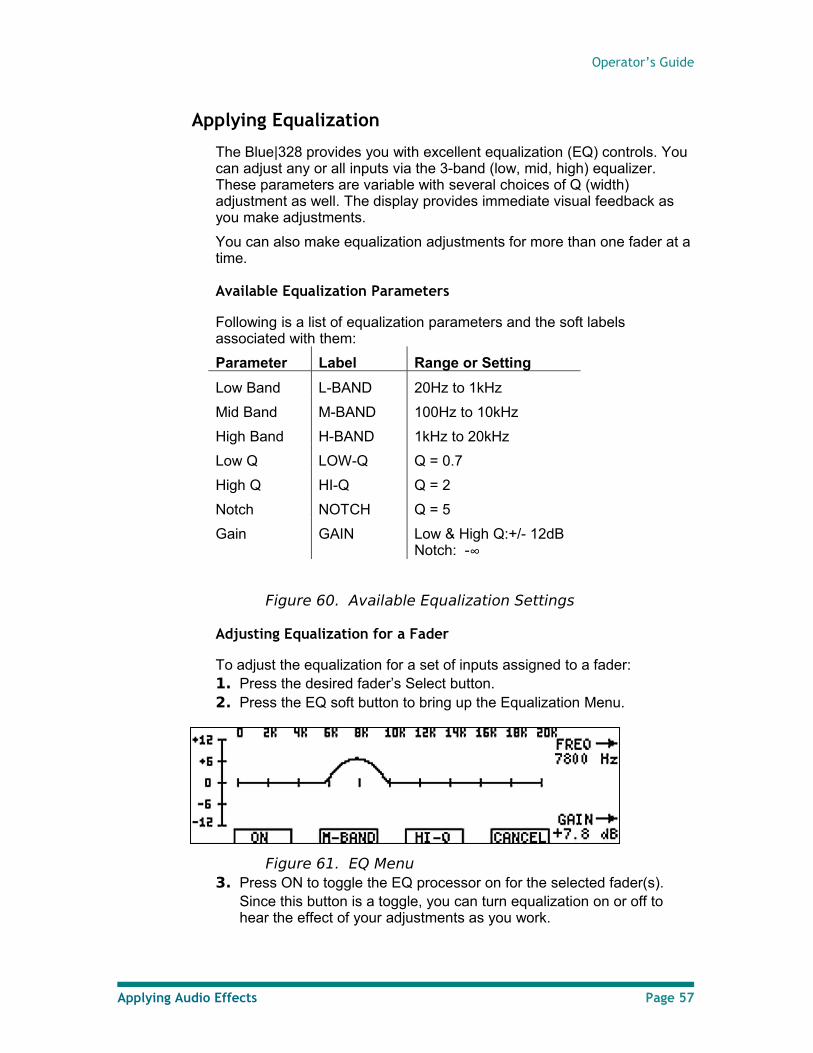
Figure 60. Available Equalization Settings
Adjusting Equalization for a Fader
To adjust the equalization for a set of inputs assigned to a fader: 1. Press the desired fader’s Select button.2. Press the EQ soft button to bring up the Equalization Menu.
Figure 61. EQ Menu3. Press ON to toggle the EQ processor on for the selected fader(s).
Since this button is a toggle, you can turn equalization on or off to hear the effect of your adjustments as you work.
Applying Audio Effects Page 57
Renegade Labs Blue|328
Note
Holding the ON soft button down for three seconds turns EQ off and restores the default settings.
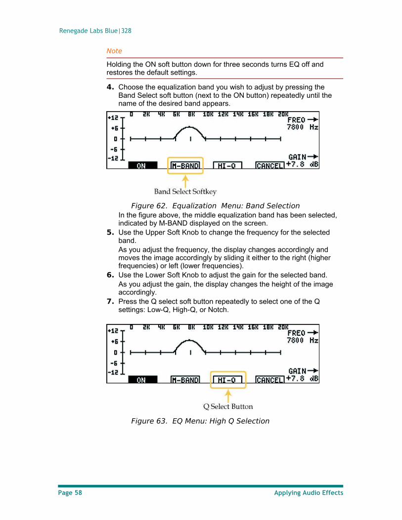
4. Choose the equalization band you wish to adjust by pressing the Band Select soft button (next to the ON button) repeatedly until the name of the desired band appears.
Figure 62. Equalization Menu: Band SelectionIn the figure above, the middle equalization band has been selected, indicated by M-BAND displayed on the screen.
5. Use the Upper Soft Knob to change the frequency for the selected band. As you adjust the frequency, the display changes accordingly and moves the image accordingly by sliding it either to the right (higher frequencies) or left (lower frequencies).
6. Use the Lower Soft Knob to adjust the gain for the selected band. As you adjust the gain, the display changes the height of the image accordingly.
7. Press the Q select soft button repeatedly to select one of the Q settings: Low-Q, High-Q, or Notch.
Figure 63. EQ Menu: High Q Selection
Page 58 Applying Audio Effects
Operator’s Guide
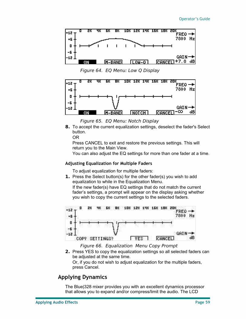
Figure 64. EQ Menu: Low Q Display
Figure 65. EQ Menu: Notch Display8. To accept the current equalization settings, deselect the fader's Select
button. ORPress CANCEL to exit and restore the previous settings. This will return you to the Main View. You can also adjust the EQ settings for more than one fader at a time.
Adjusting Equalization for Multiple Faders
To adjust equalization for multiple faders: 1. Press the Select button(s) for the other fader(s) you wish to add
equalization to while in the Equalization Menu.If the new fader(s) have EQ settings that do not match the current fader’s settings, a prompt will appear on the display asking whether you wish to copy the current settings to the selected faders.
Figure 66. Equalization Menu Copy Prompt2. Press YES to copy the equalization settings so all selected faders can
be adjusted at the same time. Or, if you do not wish to adjust equalization for the multiple faders, press Cancel.
Applying Dynamics
The Blue|328 mixer provides you with an excellent dynamics processor that allows you to expand and/or compress/limit the audio. The LCD
Applying Audio Effects Page 59
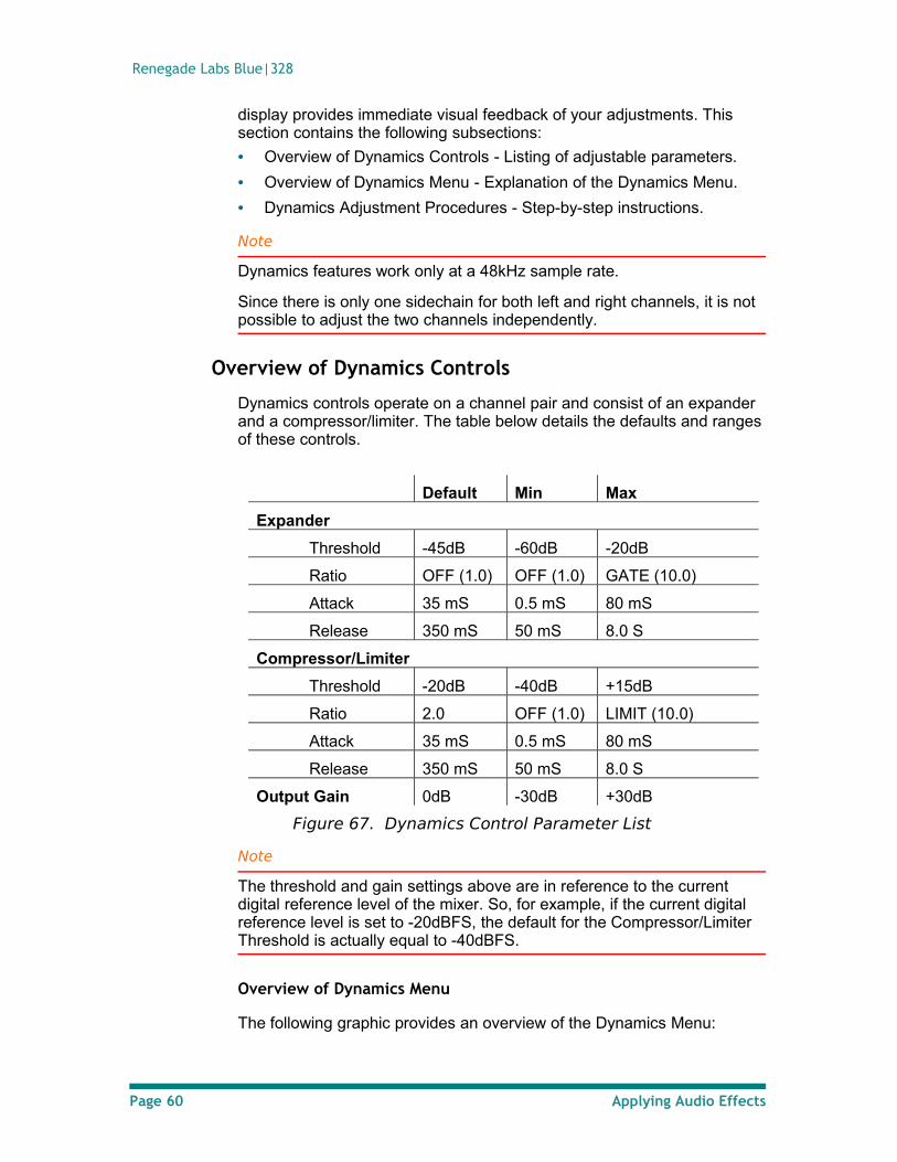
Renegade Labs Blue|328
display provides immediate visual feedback of your adjustments. This section contains the following subsections:
• Overview of Dynamics Controls - Listing of adjustable parameters.
• Overview of Dynamics Menu - Explanation of the Dynamics Menu.
• Dynamics Adjustment Procedures - Step-by-step instructions.
Note
Dynamics features work only at a 48kHz sample rate.
Since there is only one sidechain for both left and right channels, it is not possible to adjust the two channels independently.
Overview of Dynamics Controls
Dynamics controls operate on a channel pair and consist of an expander and a compressor/limiter. The table below details the defaults and ranges of these controls.
Default Min Max
Expander
Threshold -45dB -60dB -20dB
Ratio OFF (1.0) OFF (1.0) GATE (10.0)
Attack 35 mS 0.5 mS 80 mS
Release 350 mS 50 mS 8.0 S
Compressor/Limiter
Threshold -20dB -40dB +15dB
Ratio 2.0 OFF (1.0) LIMIT (10.0)
Attack 35 mS 0.5 mS 80 mS
Release 350 mS 50 mS 8.0 S
Output Gain 0dB -30dB +30dB
Figure 67. Dynamics Control Parameter List
Note
The threshold and gain settings above are in reference to the current digital reference level of the mixer. So, for example, if the current digital reference level is set to -20dBFS, the default for the Compressor/Limiter Threshold is actually equal to -40dBFS.
Overview of Dynamics Menu
The following graphic provides an overview of the Dynamics Menu:
Page 60 Applying Audio Effects
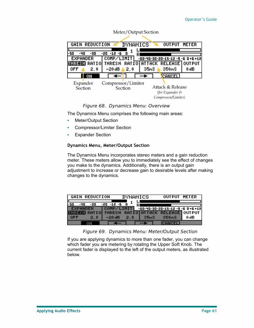
Operator’s Guide
Figure 68. Dynamics Menu: Overview
The Dynamics Menu comprises the following main areas:
• Meter/Output Section
• Compressor/Limiter Section
• Expander Section
Dynamics Menu, Meter/Output Section
The Dynamics Menu incorporates stereo meters and a gain reduction meter. These meters allow you to immediately see the effect of changes you make to the dynamics. Additionally, there is an output gain adjustment to increase or decrease gain to desirable levels after making changes to the dynamics.
Figure 69. Dynamics Menu: Meter/Output Section
If you are applying dynamics to more than one fader, you can change which fader you are metering by rotating the Upper Soft Knob. The current fader is displayed to the left of the output meters, as illustrated below.
Applying Audio Effects Page 61
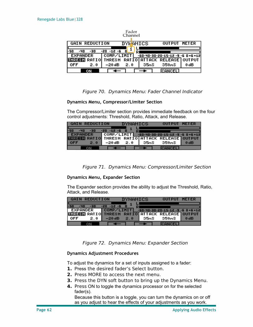
Renegade Labs Blue|328
Figure 70. Dynamics Menu: Fader Channel Indicator
Dynamics Menu, Compressor/Limiter Section
The Compressor/Limiter section provides immediate feedback on the four control adjustments: Threshold, Ratio, Attack, and Release.
Figure 71. Dynamics Menu: Compressor/Limiter Section
Dynamics Menu, Expander Section
The Expander section provides the ability to adjust the Threshold, Ratio, Attack, and Release.
Figure 72. Dynamics Menu: Expander Section
Dynamics Adjustment Procedures
To adjust the dynamics for a set of inputs assigned to a fader: 1. Press the desired fader’s Select button. 2. Press MORE to access the next menu. 3. Press the DYN soft button to bring up the Dynamics Menu. 4. Press ON to toggle the dynamics processor on for the selected
fader(s). Because this button is a toggle, you can turn the dynamics on or off as you adjust to hear the effects of your adjustments as you work.
Page 62 Applying Audio Effects
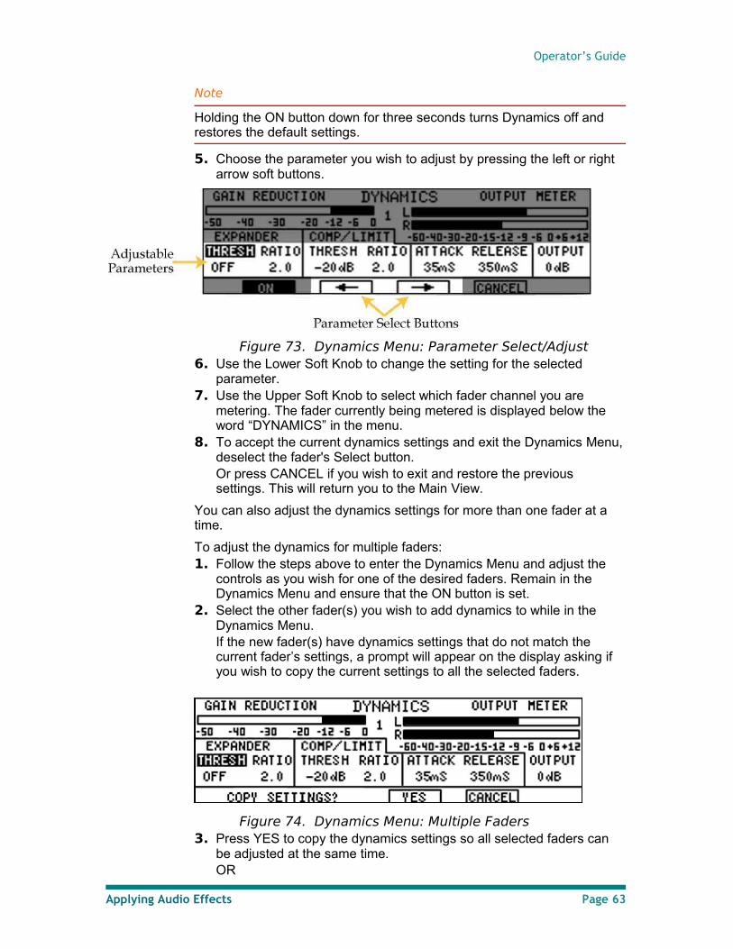
Operator’s Guide
Note
Holding the ON button down for three seconds turns Dynamics off and restores the default settings.
5. Choose the parameter you wish to adjust by pressing the left or right arrow soft buttons.
Figure 73. Dynamics Menu: Parameter Select/Adjust6. Use the Lower Soft Knob to change the setting for the selected
parameter. 7. Use the Upper Soft Knob to select which fader channel you are
metering. The fader currently being metered is displayed below the word “DYNAMICS” in the menu.
8. To accept the current dynamics settings and exit the Dynamics Menu, deselect the fader's Select button. Or press CANCEL if you wish to exit and restore the previous settings. This will return you to the Main View.
You can also adjust the dynamics settings for more than one fader at a time.
To adjust the dynamics for multiple faders: 1. Follow the steps above to enter the Dynamics Menu and adjust the
controls as you wish for one of the desired faders. Remain in the Dynamics Menu and ensure that the ON button is set.
2. Select the other fader(s) you wish to add dynamics to while in the Dynamics Menu. If the new fader(s) have dynamics settings that do not match the current fader’s settings, a prompt will appear on the display asking if you wish to copy the current settings to all the selected faders.
Figure 74. Dynamics Menu: Multiple Faders3. Press YES to copy the dynamics settings so all selected faders can
be adjusted at the same time. OR
Applying Audio Effects Page 63
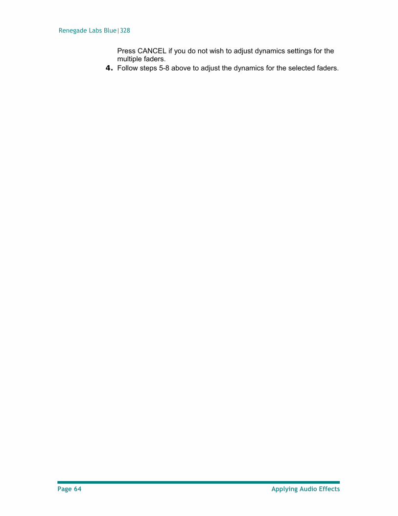
Renegade Labs Blue|328
Press CANCEL if you do not wish to adjust dynamics settings for the multiple faders.
4. Follow steps 5-8 above to adjust the dynamics for the selected faders.
Page 64 Applying Audio Effects
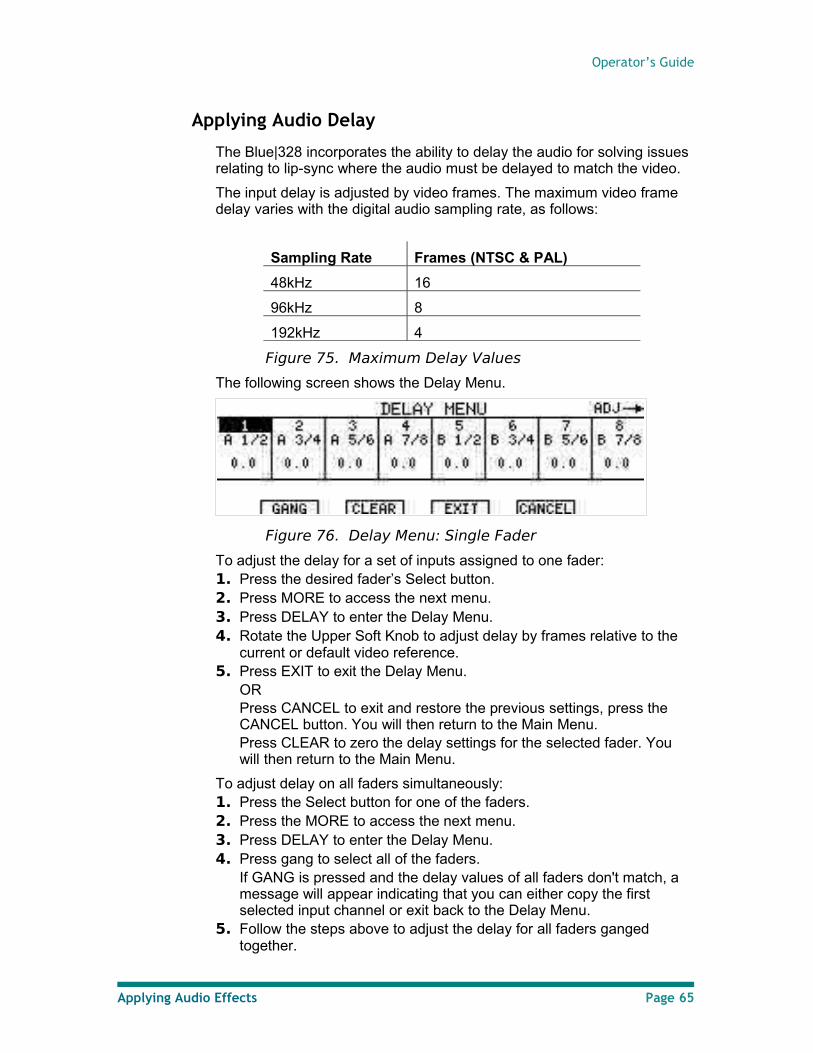
Operator’s Guide
Applying Audio Delay
The Blue|328 incorporates the ability to delay the audio for solving issues relating to lip-sync where the audio must be delayed to match the video.
The input delay is adjusted by video frames. The maximum video frame delay varies with the digital audio sampling rate, as follows:
Sampling Rate Frames (NTSC & PAL)
48kHz 16
96kHz 8
192kHz 4
Figure 75. Maximum Delay Values
The following screen shows the Delay Menu.
Figure 76. Delay Menu: Single Fader
To adjust the delay for a set of inputs assigned to one fader: 1. Press the desired fader’s Select button. 2. Press MORE to access the next menu. 3. Press DELAY to enter the Delay Menu. 4. Rotate the Upper Soft Knob to adjust delay by frames relative to the
current or default video reference. 5. Press EXIT to exit the Delay Menu.
OR Press CANCEL to exit and restore the previous settings, press the CANCEL button. You will then return to the Main Menu. Press CLEAR to zero the delay settings for the selected fader. You will then return to the Main Menu.
To adjust delay on all faders simultaneously: 1. Press the Select button for one of the faders. 2. Press the MORE to access the next menu. 3. Press DELAY to enter the Delay Menu. 4. Press gang to select all of the faders.
If GANG is pressed and the delay values of all faders don't match, a message will appear indicating that you can either copy the first selected input channel or exit back to the Delay Menu.
5. Follow the steps above to adjust the delay for all faders ganged together.
Applying Audio Effects Page 65
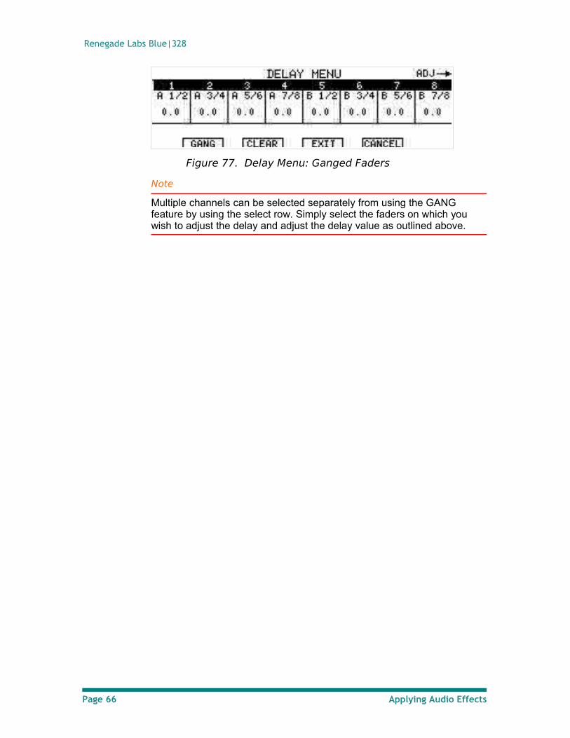
Renegade Labs Blue|328
Figure 77. Delay Menu: Ganged Faders
Note
Multiple channels can be selected separately from using the GANG feature by using the select row. Simply select the faders on which you wish to adjust the delay and adjust the delay value as outlined above.
Page 66 Applying Audio Effects
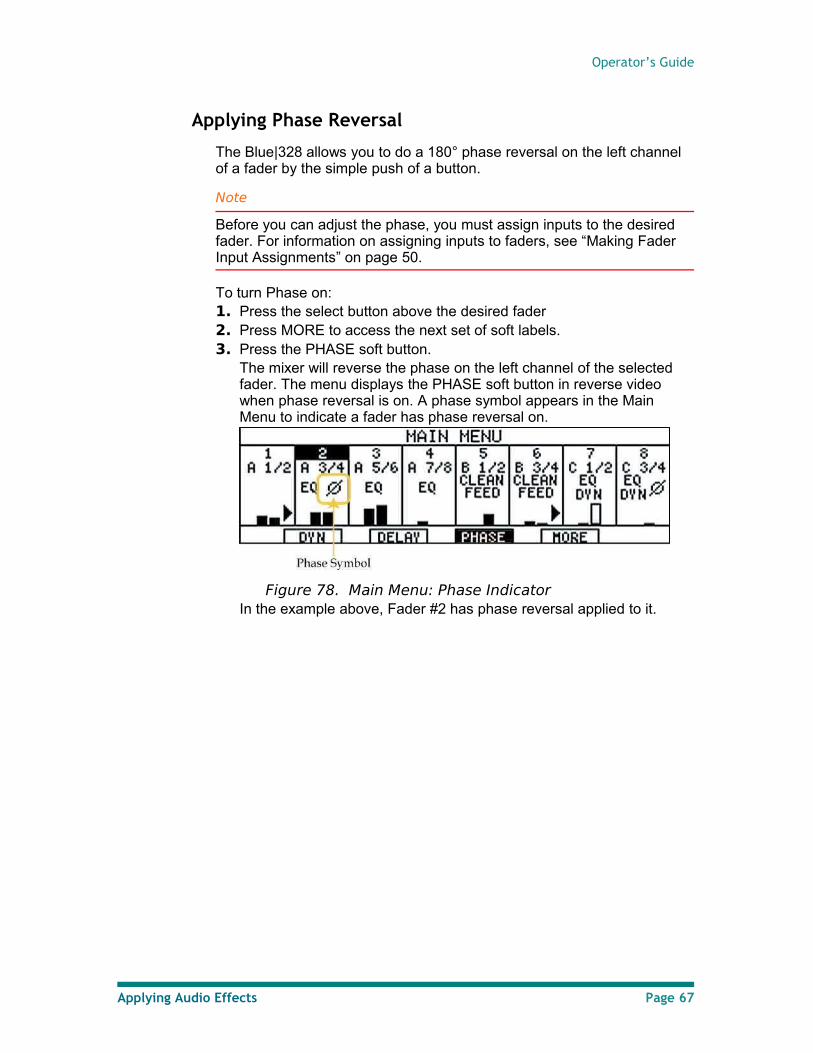
Operator’s Guide
Applying Phase Reversal
The Blue|328 allows you to do a 180° phase reversal on the left channel of a fader by the simple push of a button.
Note
Before you can adjust the phase, you must assign inputs to the desired fader. For information on assigning inputs to faders, see “Making Fader Input Assignments” on page 50.
To turn Phase on: 1. Press the select button above the desired fader 2. Press MORE to access the next set of soft labels. 3. Press the PHASE soft button.
The mixer will reverse the phase on the left channel of the selected fader. The menu displays the PHASE soft button in reverse video when phase reversal is on. A phase symbol appears in the Main Menu to indicate a fader has phase reversal on.
Figure 78. Main Menu: Phase IndicatorIn the example above, Fader #2 has phase reversal applied to it.
Applying Audio Effects Page 67
Renegade Labs Blue|328
Enabling Clean Feed
The Blue|328 allows you to send a fader's audio cleanly through the mixer without any additional effects applied. This is quite useful for making dubs.
Notes
Before you can turn Clean Feed on, you must assign inputs to the desired fader. For more information on assigning inputs to faders, see “Making Fader Input Assignments” on page 50.
Input Trim still functions while in Clean Feed mode. If you wish to maintain a unity path by using Clean Feed, you must also ensure that the input level gain is set to 0dB. See ”Trim” on page 70 for more information.
If the Clean Feed inputs are coming in to the mixer via a sample-rate-converted (SRC) input module the SRC should be bypassed on that module to achieve a clean bit-accurate feed. See “Adjusting the AES-SRC Input Module“ on page 44 for more information.
When Clean Feed is enabled, the following occurs:
• The fader can no longer be used for gain adjustment and the audio level is set to unity.
• The unity indicator for the fader is turned on.
• The Master Fader no longer effects fader channels in Clean Feed mode.
• The pan pot is no longer active and the audio balance is set to even.
• All equalizer settings are disabled.
• All dynamics settings are disabled.
• Phase reversal is disabled.
• The current routing settings are still valid.
• The Program button for the fader works normally.
• The Preset button for the fader works normally.
• The Select button for the fader works normally.
• The Trim function for input gain works normally.
When Clean Feed is disabled the following occurs:
• The fader functions normally again at its current position.
• The pan pot functions normally again at its current position.
• Any audio effects (EQ, Dynamics) that were present are restored. To turn Clean Feed on:
1. Press the desired fader’s Select button. 2. Press MORE to access the next menu. 3. Press MORE again. The Clean Feed soft label will appear on the
Main Menu display.4. Press the CLEAN soft button to activate Clean Feed Mode.
Page 68 Applying Audio Effects
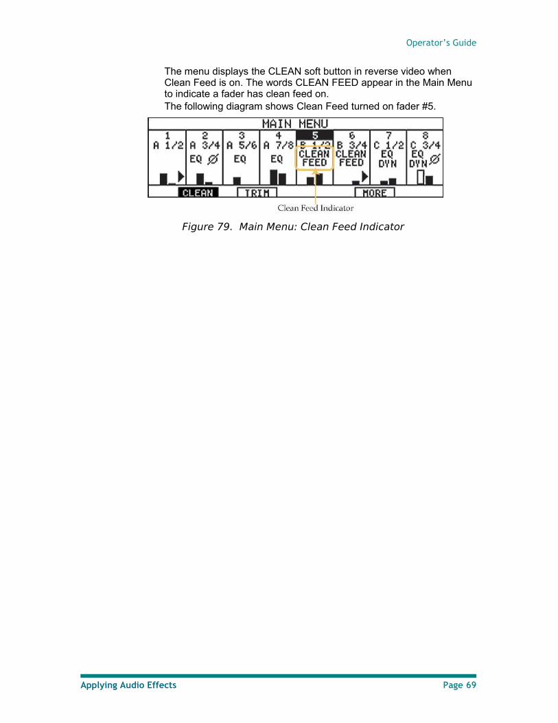
Operator’s Guide
The menu displays the CLEAN soft button in reverse video when Clean Feed is on. The words CLEAN FEED appear in the Main Menu to indicate a fader has clean feed on. The following diagram shows Clean Feed turned on fader #5.
Figure 79. Main Menu: Clean Feed Indicator
Applying Audio Effects Page 69
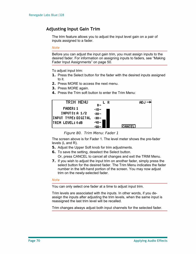
Renegade Labs Blue|328
Adjusting Input Gain Trim
The trim feature allows you to adjust the input level gain on a pair of inputs assigned to a fader.
Note
Before you can adjust the input gain trim, you must assign inputs to the desired fader. For information on assigning inputs to faders, see “Making Fader Input Assignments” on page 50.
To adjust input trim: 1. Press the Select button for the fader with the desired inputs assigned
to it.2. Press MORE to access the next menu. 3. Press MORE again. 4. Press the Trim soft button to enter the Trim Menu:
Figure 80. Trim Menu: Fader 1
The screen above is for Fader 1. The level meter shows the pre-fader levels (L and R). 5. Adjust the Upper Soft knob for trim adjustments. 6. To save the setting, deselect the Select button.
Or, press CANCEL to cancel all changes and exit the TRIM Menu.7. If you wish to adjust the input trim on another fader, simply press the
select button for the desired fader. The Trim Menu indicates the fader number in the left-hand portion of the screen. You may now adjust trim on the newly-selected fader.
Note
You can only select one fader at a time to adjust input trim.
Trim levels are associated with the inputs. In other words, if you de-assign the inputs after adjusting the trim levels, when the same input is reassigned the last trim level will be recalled.
Trim changes always adjust both input channels for the selected fader.
Page 70 Applying Audio Effects
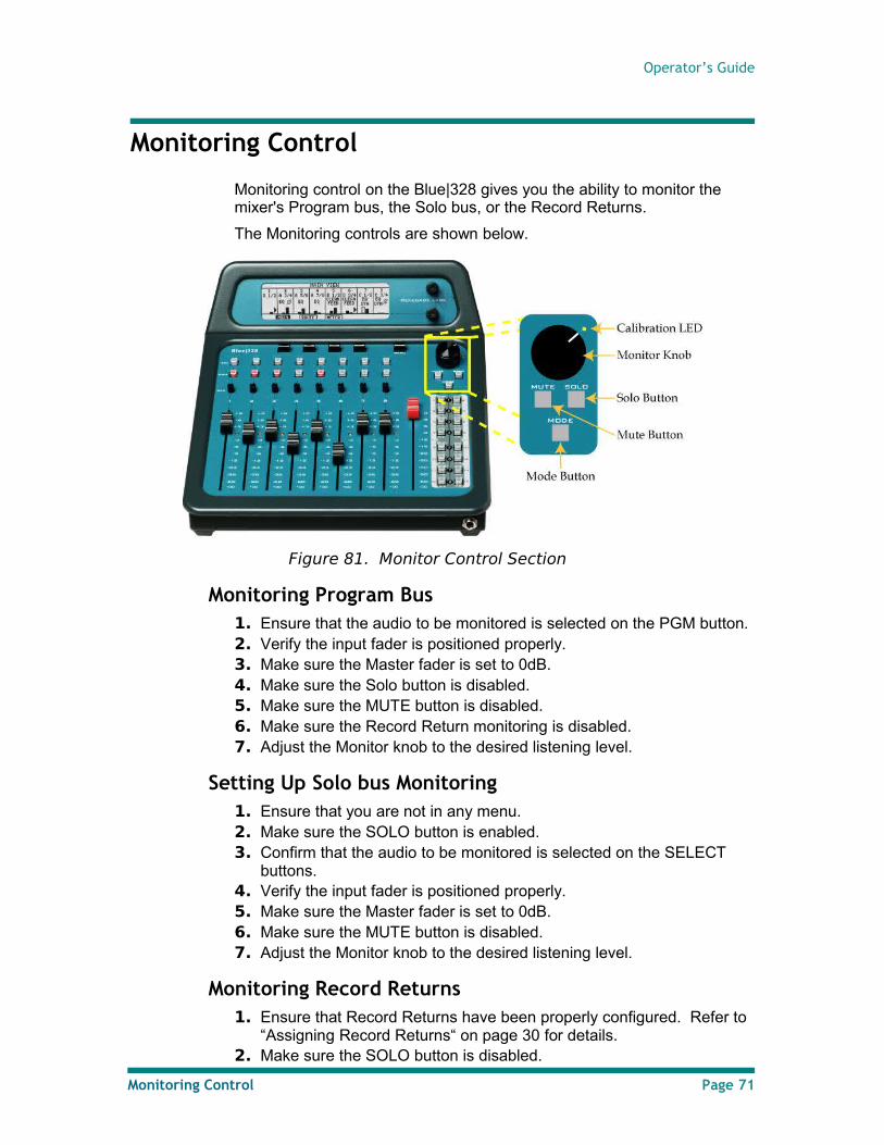
Operator’s Guide
Monitoring Control
Monitoring control on the Blue|328 gives you the ability to monitor the mixer's Program bus, the Solo bus, or the Record Returns.
The Monitoring controls are shown below.
Figure 81. Monitor Control Section
Monitoring Program Bus1. Ensure that the audio to be monitored is selected on the PGM button.2. Verify the input fader is positioned properly.3. Make sure the Master fader is set to 0dB.4. Make sure the Solo button is disabled.5. Make sure the MUTE button is disabled.6. Make sure the Record Return monitoring is disabled.7. Adjust the Monitor knob to the desired listening level.
Setting Up Solo bus Monitoring1. Ensure that you are not in any menu.2. Make sure the SOLO button is enabled.3. Confirm that the audio to be monitored is selected on the SELECT
buttons.4. Verify the input fader is positioned properly.5. Make sure the Master fader is set to 0dB.6. Make sure the MUTE button is disabled.7. Adjust the Monitor knob to the desired listening level.
Monitoring Record Returns1. Ensure that Record Returns have been properly configured. Refer to
“Assigning Record Returns“ on page 30 for details.2. Make sure the SOLO button is disabled.
Monitoring Control Page 71
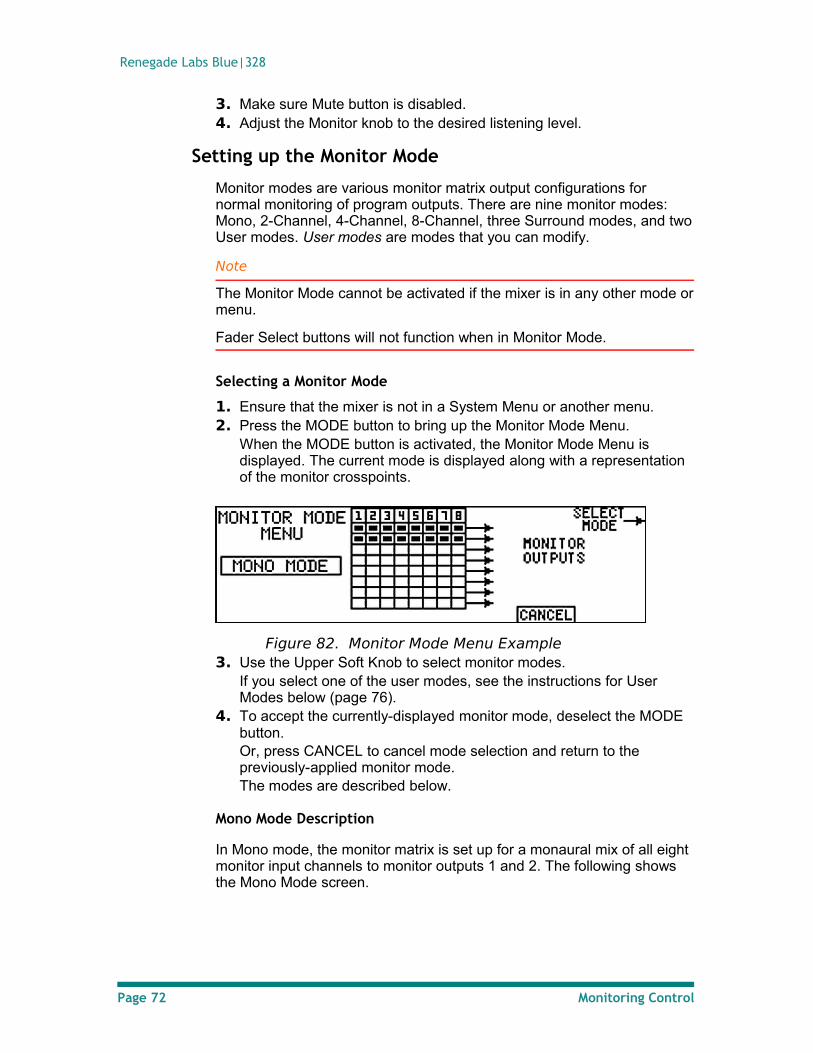
Renegade Labs Blue|328
3. Make sure Mute button is disabled.4. Adjust the Monitor knob to the desired listening level.
Setting up the Monitor Mode
Monitor modes are various monitor matrix output configurations for normal monitoring of program outputs. There are nine monitor modes: Mono, 2-Channel, 4-Channel, 8-Channel, three Surround modes, and two User modes. User modes are modes that you can modify.
Note
The Monitor Mode cannot be activated if the mixer is in any other mode or menu.
Fader Select buttons will not function when in Monitor Mode.
Selecting a Monitor Mode
1. Ensure that the mixer is not in a System Menu or another menu.2. Press the MODE button to bring up the Monitor Mode Menu.
When the MODE button is activated, the Monitor Mode Menu is displayed. The current mode is displayed along with a representation of the monitor crosspoints.
Figure 82. Monitor Mode Menu Example3. Use the Upper Soft Knob to select monitor modes.
If you select one of the user modes, see the instructions for User Modes below (page 76).
4. To accept the currently-displayed monitor mode, deselect the MODE button.Or, press CANCEL to cancel mode selection and return to the previously-applied monitor mode.The modes are described below.
Mono Mode Description
In Mono mode, the monitor matrix is set up for a monaural mix of all eight monitor input channels to monitor outputs 1 and 2. The following shows the Mono Mode screen.
Page 72 Monitoring Control
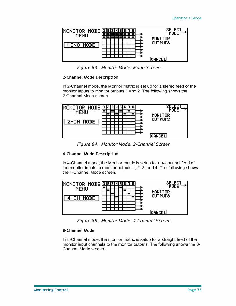
Operator’s Guide
Figure 83. Monitor Mode: Mono Screen
2-Channel Mode Description
In 2-Channel mode, the Monitor matrix is set up for a stereo feed of the monitor inputs to monitor outputs 1 and 2. The following shows the 2-Channel Mode screen.
Figure 84. Monitor Mode: 2-Channel Screen
4-Channel Mode Description
In 4-Channel mode, the Monitor matrix is setup for a 4-channel feed of the monitor inputs to monitor outputs 1, 2, 3, and 4. The following shows the 4-Channel Mode screen.
Figure 85. Monitor Mode: 4-Channel Screen
8-Channel Mode
In 8-Channel mode, the monitor matrix is setup for a straight feed of the monitor input channels to the monitor outputs. The following shows the 8-Channel Mode screen.
Monitoring Control Page 73
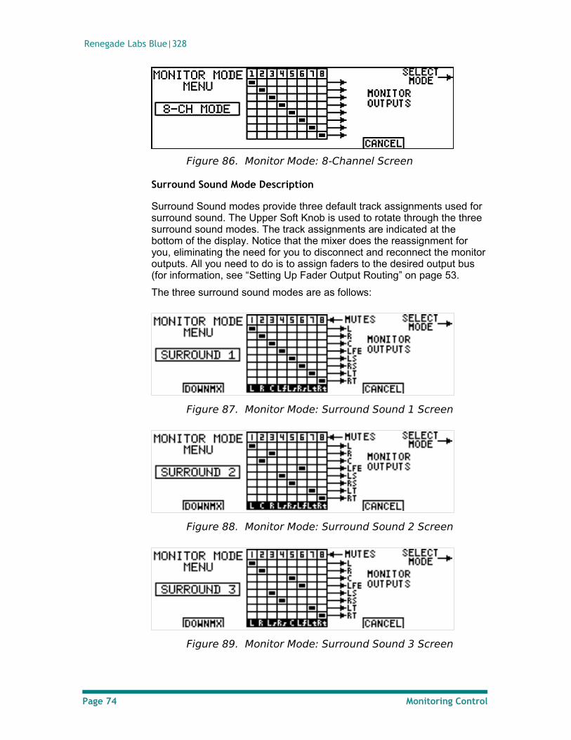
Renegade Labs Blue|328
Figure 86. Monitor Mode: 8-Channel Screen
Surround Sound Mode Description
Surround Sound modes provide three default track assignments used for surround sound. The Upper Soft Knob is used to rotate through the three surround sound modes. The track assignments are indicated at the bottom of the display. Notice that the mixer does the reassignment for you, eliminating the need for you to disconnect and reconnect the monitor outputs. All you need to do is to assign faders to the desired output bus (for information, see “Setting Up Fader Output Routing” on page 53.
The three surround sound modes are as follows:
Figure 87. Monitor Mode: Surround Sound 1 Screen
Figure 88. Monitor Mode: Surround Sound 2 Screen
Figure 89. Monitor Mode: Surround Sound 3 Screen
Page 74 Monitoring Control
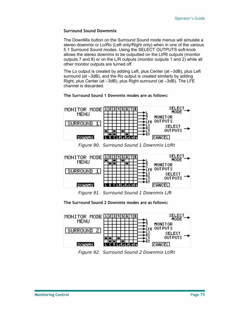
Operator’s Guide
Surround Sound Dowmmix
The DownMix button on the Surround Sound mode menus will simulate a stereo downmix or Lo/Ro (Left only/Right only) when in one of the various 5.1 Surround Sound modes. Using the SELECT OUTPUTS soft-knob allows the stereo downmix to be outputted on the Lt/Rt outputs (monitor outputs 7 and 8) or on the L/R outputs (monitor outputs 1 and 2) while all other monitor outputs are turned off.
The Lo output is created by adding Left, plus Center (at –3dB), plus Left surround (at –3dB), and the Ro output is created similarly by adding Right, plus Center (at –3dB), plus Right surround (at –3dB). The LFE channel is discarded.
The Surround Sound 1 Downmix modes are as follows:
Figure 90. Surround Sound 1 Downmix Lt/Rt
Figure 91. Surround Sound 1 Downmix L/R
The Surround Sound 2 Downmix modes are as follows:
Figure 92. Surround Sound 2 Downmix Lt/Rt
Monitoring Control Page 75
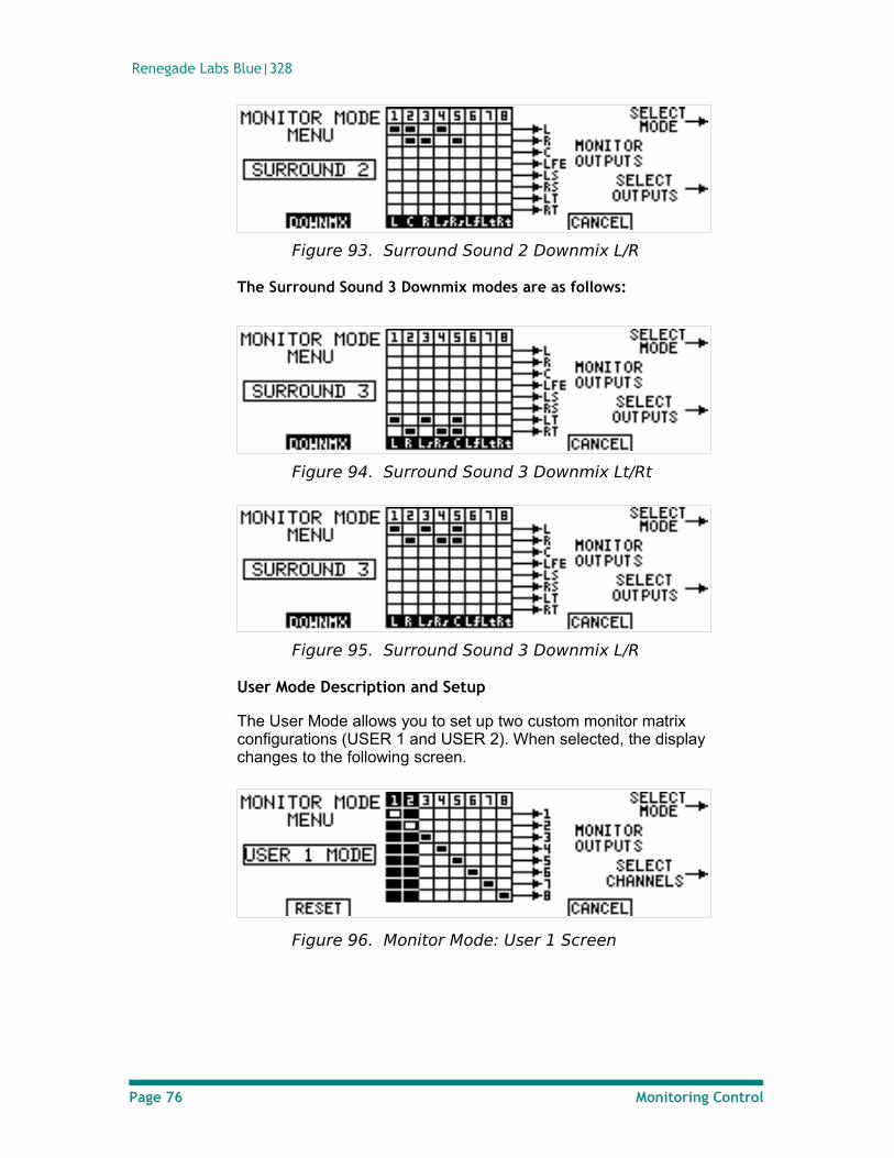
Renegade Labs Blue|328
Figure 93. Surround Sound 2 Downmix L/R
The Surround Sound 3 Downmix modes are as follows:
Figure 94. Surround Sound 3 Downmix Lt/Rt
Figure 95. Surround Sound 3 Downmix L/R
User Mode Description and Setup
The User Mode allows you to set up two custom monitor matrix configurations (USER 1 and USER 2). When selected, the display changes to the following screen.
Figure 96. Monitor Mode: User 1 Screen
Page 76 Monitoring Control
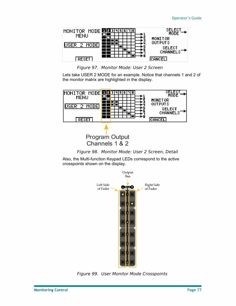
Operator’s Guide
Figure 97. Monitor Mode: User 2 Screen
Lets take USER 2 MODE for an example. Notice that channels 1 and 2 of the monitor matrix are highlighted in the display.
Figure 98. Monitor Mode: User 2 Screen, Detail
Also, the Multi-function Keypad LEDs correspond to the active crosspoints shown on the display.
Figure 99. User Monitor Mode Crosspoints
Monitoring Control Page 77
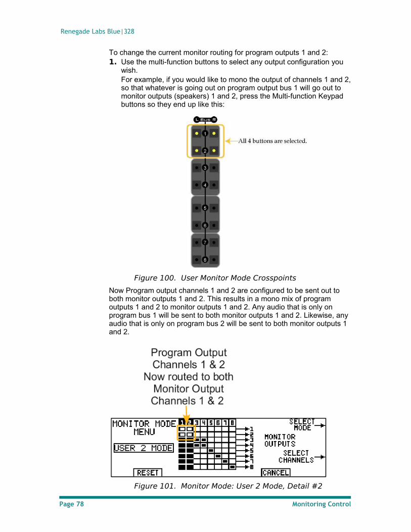
Renegade Labs Blue|328
To change the current monitor routing for program outputs 1 and 2:1. Use the multi-function buttons to select any output configuration you
wish. For example, if you would like to mono the output of channels 1 and 2, so that whatever is going out on program output bus 1 will go out to monitor outputs (speakers) 1 and 2, press the Multi-function Keypad buttons so they end up like this:
Figure 100. User Monitor Mode Crosspoints
Now Program output channels 1 and 2 are configured to be sent out to both monitor outputs 1 and 2. This results in a mono mix of program outputs 1 and 2 to monitor outputs 1 and 2. Any audio that is only on program bus 1 will be sent to both monitor outputs 1 and 2. Likewise, any audio that is only on program bus 2 will be sent to both monitor outputs 1 and 2.
Figure 101. Monitor Mode: User 2 Mode, Detail #2
Page 78 Monitoring Control
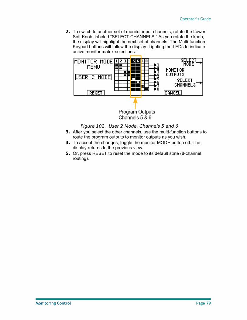
Operator’s Guide
2. To switch to another set of monitor input channels, rotate the Lower Soft Knob, labeled “SELECT CHANNELS.” As you rotate the knob, the display will highlight the next set of channels. The Multi-function Keypad buttons will follow the display. Lighting the LEDs to indicate active monitor matrix selections.
Figure 102. User 2 Mode, Channels 5 and 63. After you select the other channels, use the multi-function buttons to
route the program outputs to monitor outputs as you wish. 4. To accept the changes, toggle the monitor MODE button off. The
display returns to the previous view. 5. Or, press RESET to reset the mode to its default state (8-channel
routing).
Monitoring Control Page 79

Renegade Labs Blue|328
Memory Save/Recall
The mixer allows you to take up to 200 snapshots of the mixer’s settings, and recall them. At each memory save, the current control panel settings are stored in a register. During recall, the settings stored in a register are applied to the control panel.
Note
You can only Save/Recall a register when you are not in any menu (Select, System Menu, or Monitor Mode).
Because flash memory is used, setups saved to memory are not lost if power is removed.
What is stored during a Memory Save
During a Memory Save, the following settings are stored for later recall.
• Input Assignment
• EQ • Phase
• Mute • Headphone Output
Routing • Digital Reference Level • Delay
• Input Level Trim • Output Assignment
• Monitor Mode • Solo
• Headphone Level • Sample Rate
• Panel LED Level • Clean Feed
• Fader levels• Pan Pot positions
• Record Return• Loudness Monitoring
Figure 103. Memory Save Contents
Note
Monitor level, Master Fader setting, Reference source, Output Function, and Module settings are not stored during a memory save.
Page 80 Memory Save/Recall
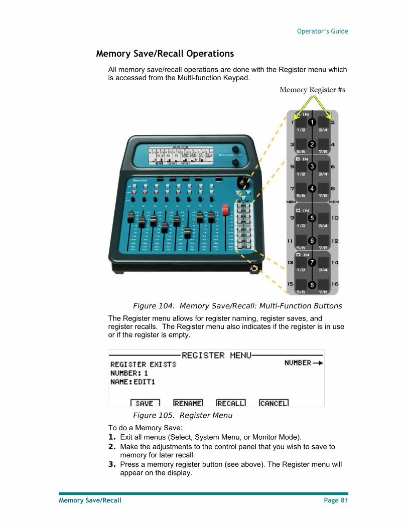
Operator’s Guide
Memory Save/Recall Operations
All memory save/recall operations are done with the Register menu which is accessed from the Multi-function Keypad.
Figure 104. Memory Save/Recall: Multi-Function Buttons
The Register menu allows for register naming, register saves, and register recalls. The Register menu also indicates if the register is in use or if the register is empty.
Figure 105. Register Menu
To do a Memory Save: 1. Exit all menus (Select, System Menu, or Monitor Mode).2. Make the adjustments to the control panel that you wish to save to
memory for later recall.3. Press a memory register button (see above). The Register menu will
appear on the display.
Memory Save/Recall Page 81

Renegade Labs Blue|328
Figure 106. Register MenuIf the register is already used REGISTER EXISTS will appear. If a different or empty register is desired either scroll using the upper soft knob or select a different register button with the Multi-function Keypad.
Note
Only register numbers 1 – 16 can be accessed via the Multi-function Keypad. For all other register numbers the upper soft knob must be used.
4. Press the SAVE soft button to save the register.
To do a Memory Recall: 1. Press a memory register button (see above). The Register menu will
appear on the display.
Figure 107. Register MenuIf the desired register to recall exists REGISTER EXISTS will appear along with the RECALL soft button. If the register is empty the RECALL button will not appear.
2. Press the RECALL soft button to recall the selcted registerOR Scroll to another register using the upper soft knob. Select a different register using the Multi-function Keypad.
Note
Only register numbers 1 – 16 can be accessed via the Multi-function Keypad. For all other register numbers the upper soft knob must be used.
• The recalled settings may be viewed in the LCD Views. Fader and pan pot settings, as well as audio offset (see below), are also indicated in the Fader Level View. These settings are also reflected in the Unity LED on the fader strip and the pan pot indicators on the Main View. For more detail, see “Main View”, page 22; “Fader Level View”, page 28; and “Unity LED”, page 13.
Page 82 Memory Save/Recall
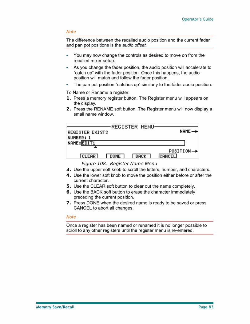
Operator’s Guide
Note
The difference between the recalled audio position and the current fader and pan pot positions is the audio offset.
• You may now change the controls as desired to move on from the recalled mixer setup.
• As you change the fader position, the audio position will accelerate to “catch up” with the fader position. Once this happens, the audio position will match and follow the fader position.
• The pan pot position “catches up” similarly to the fader audio position.
To Name or Rename a register:1. Press a memory register button. The Register menu will appears on
the display.2. Press the RENAME soft button. The Register menu will now display a
small name window.
Figure 108. Register Name Menu3. Use the upper soft knob to scroll the letters, number, and characters.4. Use the lower soft knob to move the position either before or after the
current character.5. Use the CLEAR soft button to clear out the name completely.6. Use the BACK soft button to erase the character immediately
preceding the current position.7. Press DONE when the desired name is ready to be saved or press
CANCEL to abort all changes.
Note
Once a register has been named or renamed it is no longer possible to scroll to any other registers until the register menu is re-entered.
Memory Save/Recall Page 83
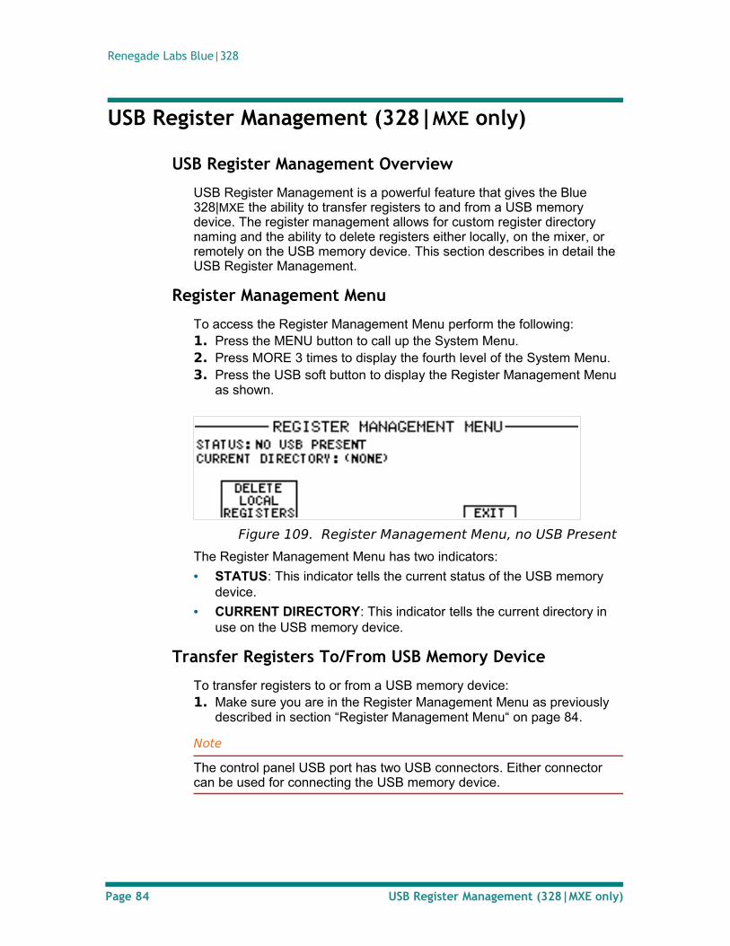
Renegade Labs Blue|328
USB Register Management (328|MXE only)
USB Register Management Overview
USB Register Management is a powerful feature that gives the Blue 328|MXE the ability to transfer registers to and from a USB memory device. The register management allows for custom register directory naming and the ability to delete registers either locally, on the mixer, or remotely on the USB memory device. This section describes in detail the USB Register Management.
Register Management Menu
To access the Register Management Menu perform the following:1. Press the MENU button to call up the System Menu.2. Press MORE 3 times to display the fourth level of the System Menu.3. Press the USB soft button to display the Register Management Menu
as shown.
Figure 109. Register Management Menu, no USB Present
The Register Management Menu has two indicators:
• STATUS: This indicator tells the current status of the USB memory device.
• CURRENT DIRECTORY: This indicator tells the current directory in use on the USB memory device.
Transfer Registers To/From USB Memory Device
To transfer registers to or from a USB memory device:1. Make sure you are in the Register Management Menu as previously
described in section “Register Management Menu“ on page 84.
Note
The control panel USB port has two USB connectors. Either connector can be used for connecting the USB memory device.
Page 84 USB Register Management (328|MXE only)
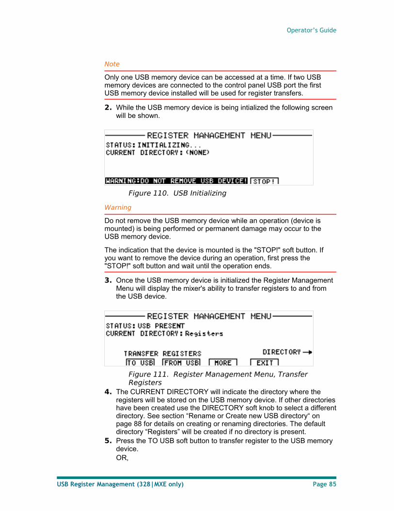
Operator’s Guide
Note
Only one USB memory device can be accessed at a time. If two USB memory devices are connected to the control panel USB port the first USB memory device installed will be used for register transfers.
2. While the USB memory device is being intialized the following screen will be shown.
Figure 110. USB Initializing
Warning
Do not remove the USB memory device while an operation (device is mounted) is being performed or permanent damage may occur to the USB memory device.
The indication that the device is mounted is the "STOP!" soft button. If you want to remove the device during an operation, first press the "STOP!" soft button and wait until the operation ends.
3. Once the USB memory device is initialized the Register Management Menu will display the mixer's ability to transfer registers to and from the USB device.
Figure 111. Register Management Menu, Transfer Registers
4. The CURRENT DIRECTORY will indicate the directory where the registers will be stored on the USB memory device. If other directories have been created use the DIRECTORY soft knob to select a different directory. See section “Rename or Create new USB directory“ on page 88 for details on creating or renaming directories. The default directory “Registers” will be created if no directory is present.
5. Press the TO USB soft button to transfer register to the USB memory device.OR,
USB Register Management (328|MXE only) Page 85
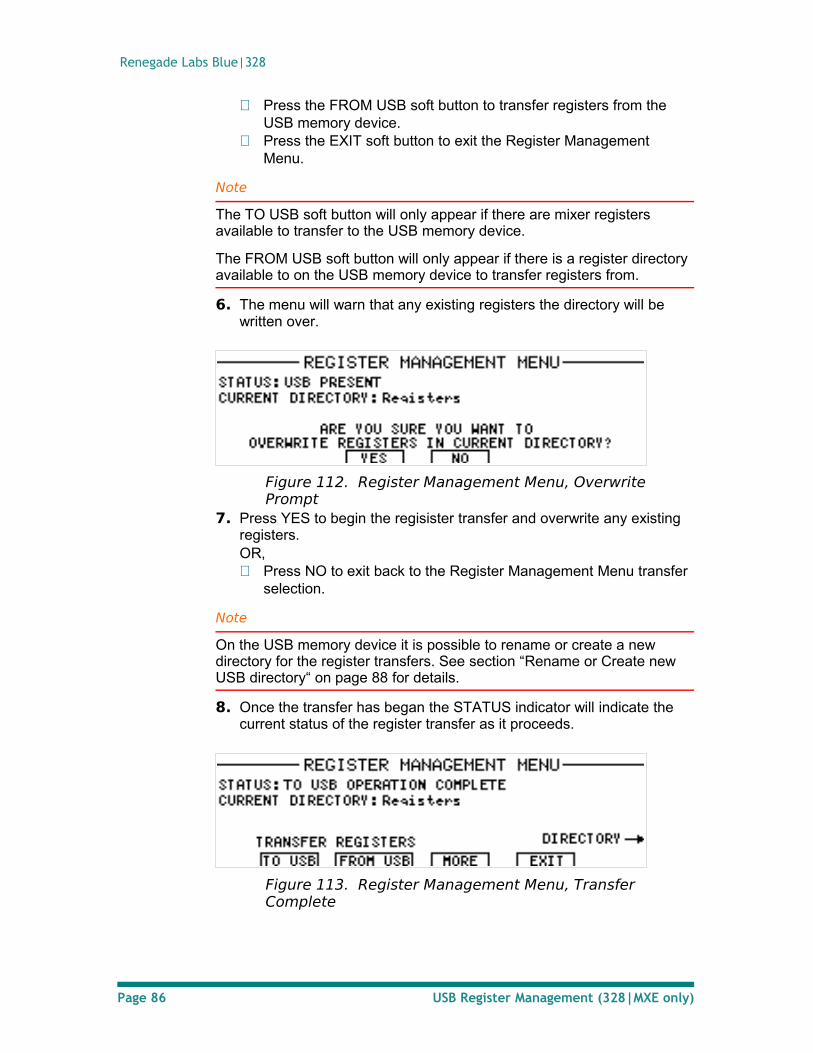
Renegade Labs Blue|328
Press the FROM USB soft button to transfer registers from the USB memory device.
Press the EXIT soft button to exit the Register Management Menu.
Note
The TO USB soft button will only appear if there are mixer registers available to transfer to the USB memory device.
The FROM USB soft button will only appear if there is a register directory available to on the USB memory device to transfer registers from.
6. The menu will warn that any existing registers the directory will be written over.
Figure 112. Register Management Menu, Overwrite Prompt
7. Press YES to begin the regisister transfer and overwrite any existing registers.OR, Press NO to exit back to the Register Management Menu transfer
selection.
Note
On the USB memory device it is possible to rename or create a new directory for the register transfers. See section “Rename or Create new USB directory“ on page 88 for details.
8. Once the transfer has began the STATUS indicator will indicate the current status of the register transfer as it proceeds.
Figure 113. Register Management Menu, Transfer Complete
Page 86 USB Register Management (328|MXE only)
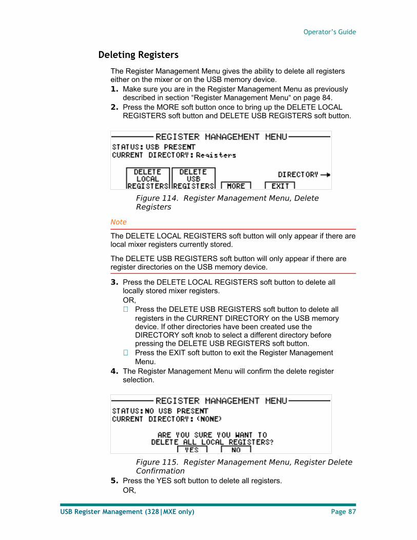
Operator’s Guide
Deleting Registers
The Register Management Menu gives the ability to delete all registers either on the mixer or on the USB memory device.1. Make sure you are in the Register Management Menu as previously
described in section “Register Management Menu“ on page 84.2. Press the MORE soft button once to bring up the DELETE LOCAL
REGISTERS soft button and DELETE USB REGISTERS soft button.
Figure 114. Register Management Menu, Delete Registers
Note
The DELETE LOCAL REGISTERS soft button will only appear if there are local mixer registers currently stored.
The DELETE USB REGISTERS soft button will only appear if there are register directories on the USB memory device.
3. Press the DELETE LOCAL REGISTERS soft button to delete all locally stored mixer registers.OR, Press the DELETE USB REGISTERS soft button to delete all
registers in the CURRENT DIRECTORY on the USB memory device. If other directories have been created use the DIRECTORY soft knob to select a different directory before pressing the DELETE USB REGISTERS soft button.
Press the EXIT soft button to exit the Register Management Menu.
4. The Register Management Menu will confirm the delete register selection.
Figure 115. Register Management Menu, Register Delete Confirmation
5. Press the YES soft button to delete all registers.OR,
USB Register Management (328|MXE only) Page 87
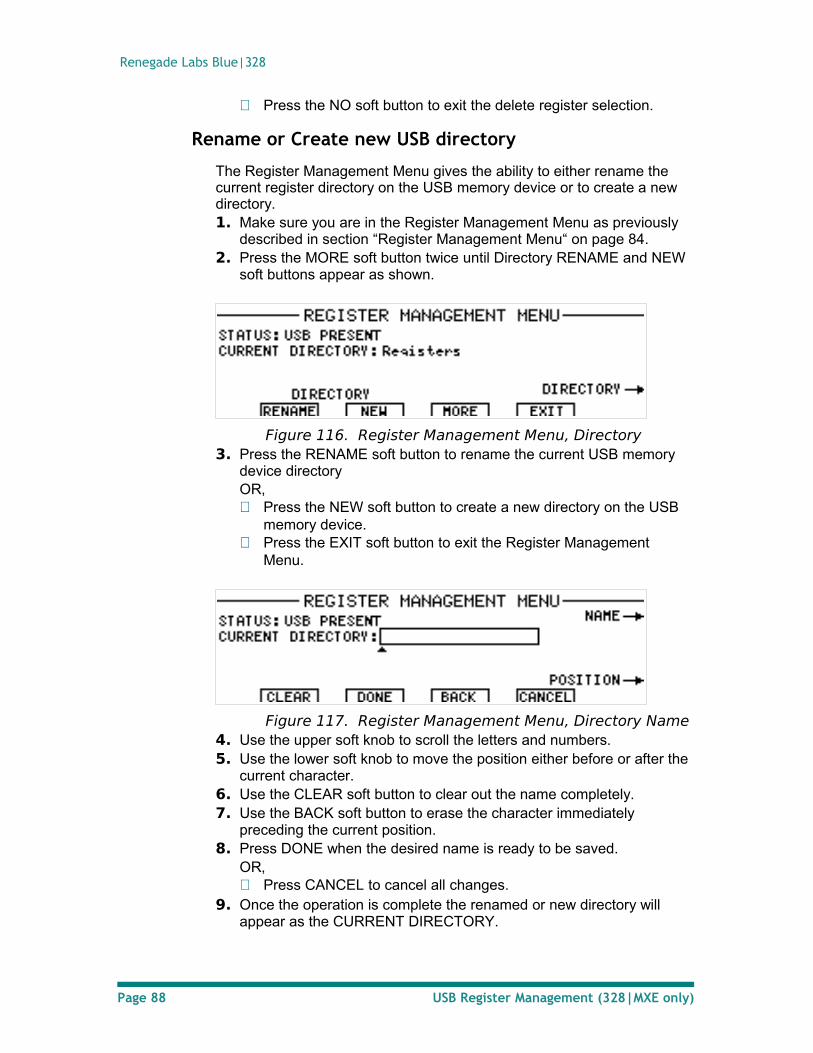
Renegade Labs Blue|328
Press the NO soft button to exit the delete register selection.
Rename or Create new USB directory
The Register Management Menu gives the ability to either rename the current register directory on the USB memory device or to create a new directory.1. Make sure you are in the Register Management Menu as previously
described in section “Register Management Menu“ on page 84.2. Press the MORE soft button twice until Directory RENAME and NEW
soft buttons appear as shown.
Figure 116. Register Management Menu, Directory3. Press the RENAME soft button to rename the current USB memory
device directoryOR, Press the NEW soft button to create a new directory on the USB
memory device. Press the EXIT soft button to exit the Register Management
Menu.
Figure 117. Register Management Menu, Directory Name4. Use the upper soft knob to scroll the letters and numbers.5. Use the lower soft knob to move the position either before or after the
current character.6. Use the CLEAR soft button to clear out the name completely.7. Use the BACK soft button to erase the character immediately
preceding the current position.8. Press DONE when the desired name is ready to be saved.
OR, Press CANCEL to cancel all changes.
9. Once the operation is complete the renamed or new directory will appear as the CURRENT DIRECTORY.
Page 88 USB Register Management (328|MXE only)
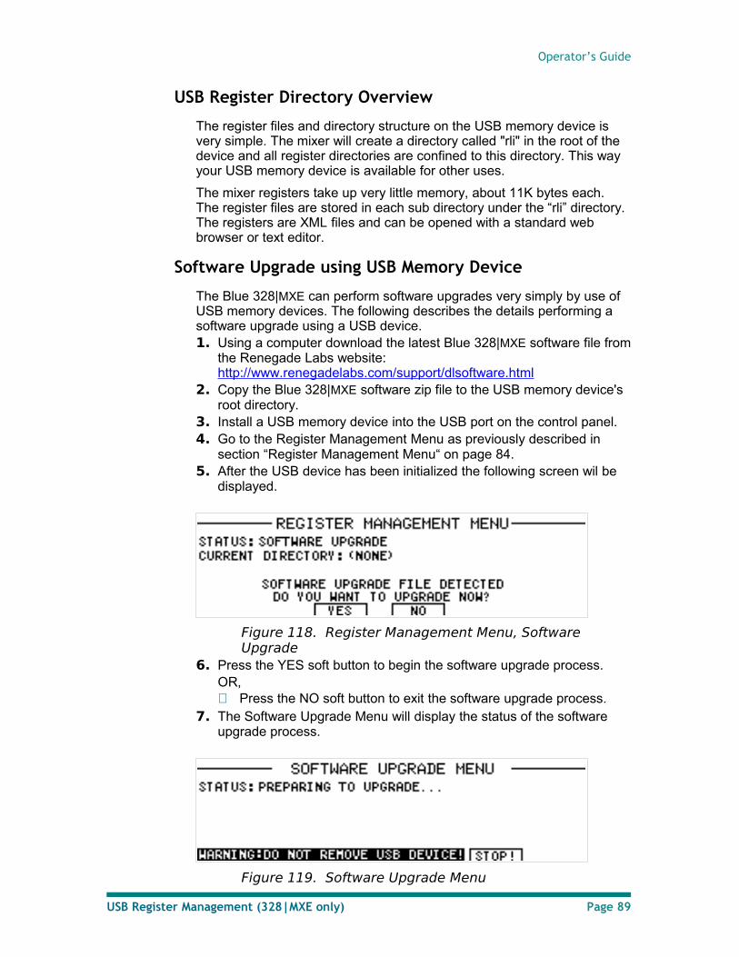
Operator’s Guide
USB Register Directory Overview
The register files and directory structure on the USB memory device is very simple. The mixer will create a directory called "rli" in the root of the device and all register directories are confined to this directory. This way your USB memory device is available for other uses.
The mixer registers take up very little memory, about 11K bytes each. The register files are stored in each sub directory under the “rli” directory. The registers are XML files and can be opened with a standard web browser or text editor.
Software Upgrade using USB Memory Device
The Blue 328|MXE can perform software upgrades very simply by use of USB memory devices. The following describes the details performing a software upgrade using a USB device.1. Using a computer download the latest Blue 328|MXE software file from
the Renegade Labs website: http://www.renegadelabs.com/support/dlsoftware.html
2. Copy the Blue 328|MXE software zip file to the USB memory device's root directory.
3. Install a USB memory device into the USB port on the control panel.4. Go to the Register Management Menu as previously described in
section “Register Management Menu“ on page 84.5. After the USB device has been initialized the following screen wil be
displayed.
Figure 118. Register Management Menu, Software Upgrade
6. Press the YES soft button to begin the software upgrade process.OR, Press the NO soft button to exit the software upgrade process.
7. The Software Upgrade Menu will display the status of the software upgrade process.
Figure 119. Software Upgrade Menu
USB Register Management (328|MXE only) Page 89
Renegade Labs Blue|328
Note
Once the software upgrade process begins it can only be stopped by pressing the STOP! soft button.
Do not remove the USB memory device while the software upgrade is being performed or permanent damage may occur to the USB memory device.
The software upgrade process takes approximately 90 seconds and the mixer will re-boot when the upgrade has been completed.
Page 90 USB Register Management (328|MXE only)
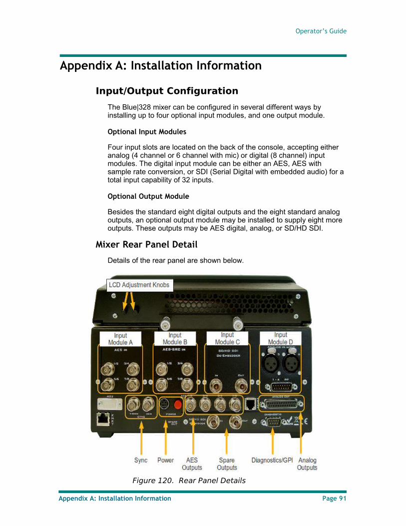
Operator’s Guide
Appendix A: Installation Information
Input/Output Configuration
The Blue|328 mixer can be configured in several different ways by installing up to four optional input modules, and one output module.
Optional Input Modules
Four input slots are located on the back of the console, accepting either analog (4 channel or 6 channel with mic) or digital (8 channel) input modules. The digital input module can be either an AES, AES with sample rate conversion, or SDI (Serial Digital with embedded audio) for a total input capability of 32 inputs.
Optional Output Module
Besides the standard eight digital outputs and the eight standard analog outputs, an optional output module may be installed to supply eight more outputs. These outputs may be AES digital, analog, or SD/HD SDI.
Mixer Rear Panel Detail
Details of the rear panel are shown below.
Figure 120. Rear Panel Details
Appendix A: Installation Information Page 91
Renegade Labs Blue|328
LCD Adjustment Knobs
Two knobs on the rear of the panel set the brightness and contrast of the LCD display. The knob on the left (as seen from the rear) adjusts the LCD backlight brightness. The knob on the right adjusts the LCD contrast.
Input Modules
There are four input module slots in the back of the control panel. The slots are labeled A, B, C, and D from left to right (as seen from the rear).
Each slot can accept several different types of input modules. These are typically installed at the factory, but can be installed by the user. Please consult the Blue|328 and Gray|328 Installation Guide for detailed information on installing input modules.
Sync
There is an input connector for Video and/or AES sync.
Power
The factory-supplied power supply must be attached to this connector. This is a locking connector to prevent accidental release.
AES Outputs
Four AES outputs (8 channels) are provided via BNC connectors.
Spare Outputs
The spare outputs can be either analog or digital, depending upon which optional output module is installed. For pinout information, please refer to the Installation Guide.
Analog Outputs
Eight analog outputs are provided via a 25-pin D-Sub connector.
Diagnostics/GPI (optional)
The Blue|328 Diagnostics port can be installed with an optional GPI interface. The optional GPI interface allows for 4 GPI inputs that can be used for recalling registers and monitoring control. Refer to “Appendix C: Diagnostic Port/GPI Option” on page 94 for more information regarding the optional GPI interface.
Page 92 Appendix A: Installation Information
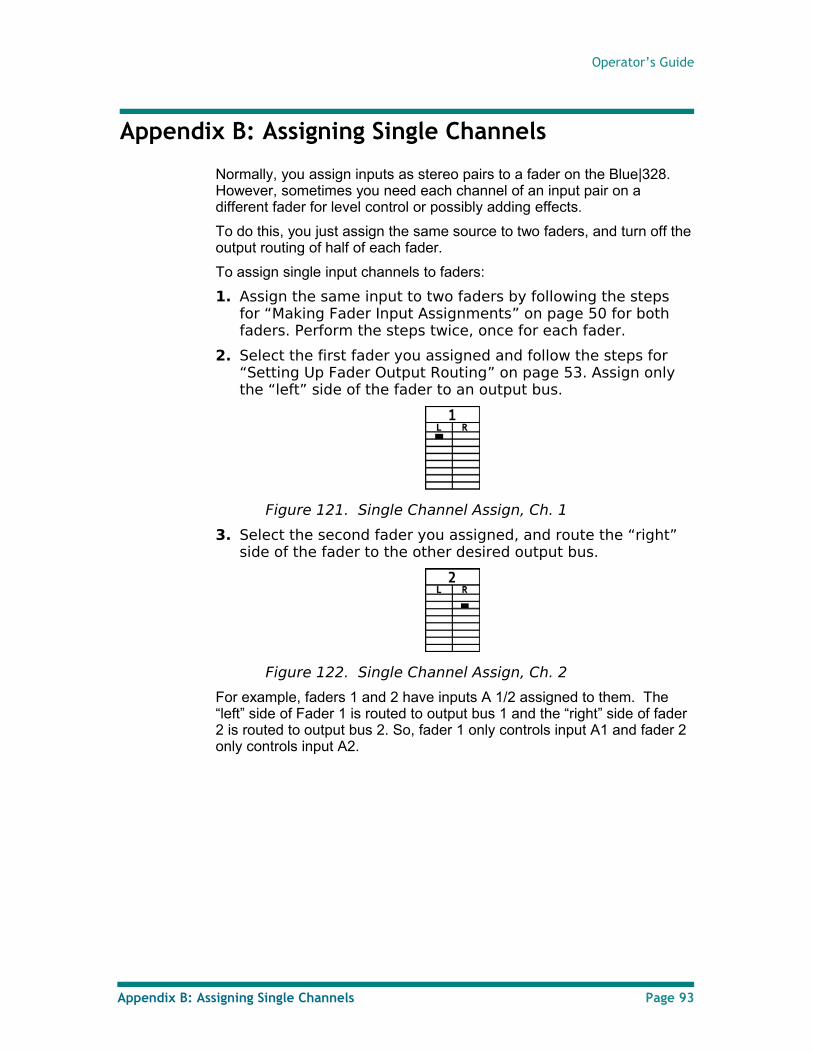
Operator’s Guide
Appendix B: Assigning Single Channels
Normally, you assign inputs as stereo pairs to a fader on the Blue|328. However, sometimes you need each channel of an input pair on a different fader for level control or possibly adding effects.
To do this, you just assign the same source to two faders, and turn off the output routing of half of each fader.
To assign single input channels to faders:
1. Assign the same input to two faders by following the steps for “Making Fader Input Assignments” on page 50 for both faders. Perform the steps twice, once for each fader.
2. Select the first fader you assigned and follow the steps for “Setting Up Fader Output Routing” on page 53. Assign only the “left” side of the fader to an output bus.
Figure 121. Single Channel Assign, Ch. 1
3. Select the second fader you assigned, and route the “right” side of the fader to the other desired output bus.
Figure 122. Single Channel Assign, Ch. 2
For example, faders 1 and 2 have inputs A 1/2 assigned to them. The “left” side of Fader 1 is routed to output bus 1 and the “right” side of fader 2 is routed to output bus 2. So, fader 1 only controls input A1 and fader 2 only controls input A2.
Appendix B: Assigning Single Channels Page 93
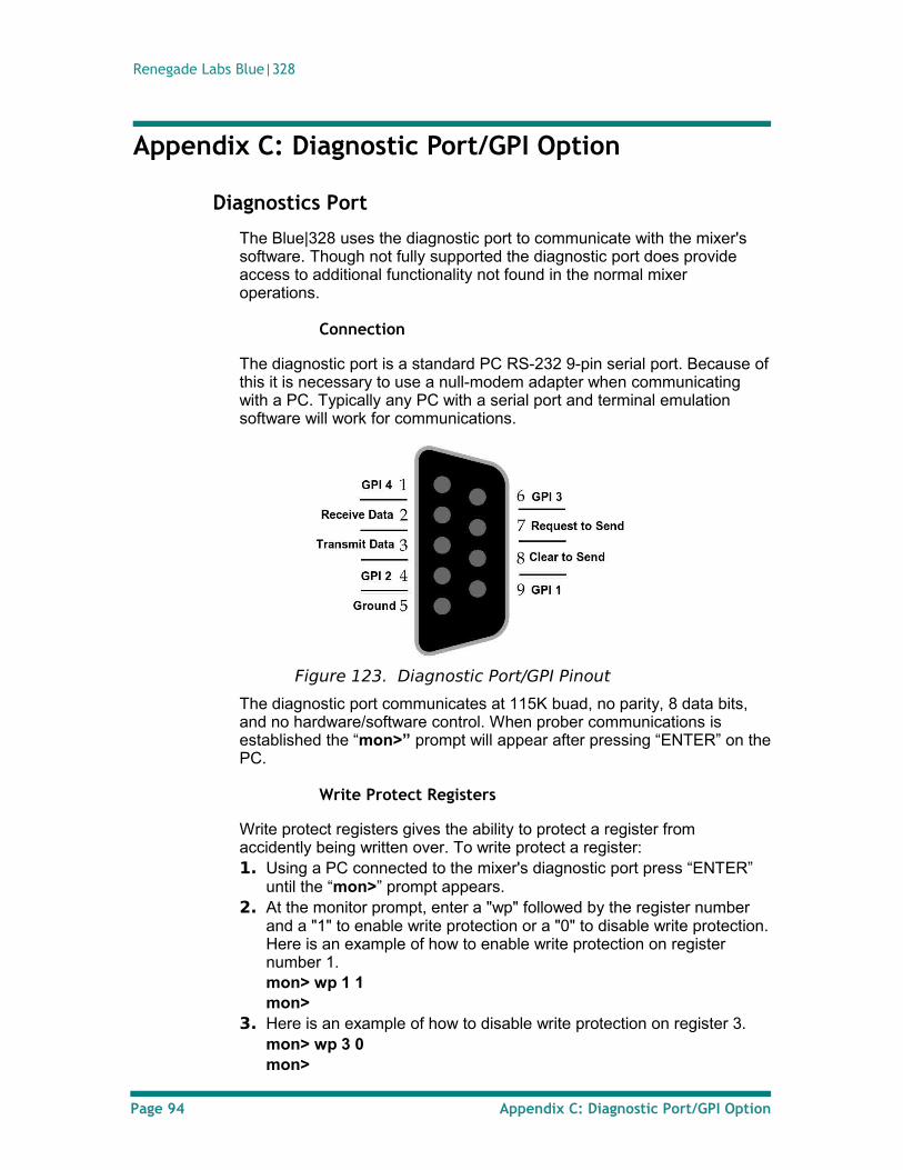
Renegade Labs Blue|328
Appendix C: Diagnostic Port/GPI Option
Diagnostics Port
The Blue|328 uses the diagnostic port to communicate with the mixer's software. Though not fully supported the diagnostic port does provide access to additional functionality not found in the normal mixer operations.
Connection
The diagnostic port is a standard PC RS-232 9-pin serial port. Because of this it is necessary to use a null-modem adapter when communicating with a PC. Typically any PC with a serial port and terminal emulation software will work for communications.
Figure 123. Diagnostic Port/GPI Pinout
The diagnostic port communicates at 115K buad, no parity, 8 data bits, and no hardware/software control. When prober communications is established the “mon>” prompt will appear after pressing “ENTER” on the PC.
Write Protect Registers
Write protect registers gives the ability to protect a register from accidently being written over. To write protect a register:1. Using a PC connected to the mixer's diagnostic port press “ENTER”
until the “mon>” prompt appears.2. At the monitor prompt, enter a "wp" followed by the register number
and a "1" to enable write protection or a "0" to disable write protection. Here is an example of how to enable write protection on register number 1.mon> wp 1 1mon>
3. Here is an example of how to disable write protection on register 3.mon> wp 3 0mon>
Page 94 Appendix C: Diagnostic Port/GPI Option
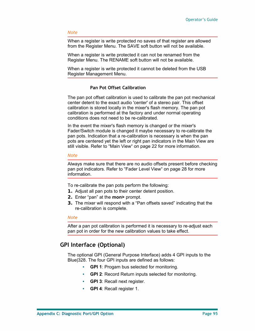
Operator’s Guide
Note
When a register is write protected no saves of that register are allowed from the Register Menu. The SAVE soft button will not be available.
When a register is write protected it can not be renamed from the Register Menu. The RENAME soft button will not be available.
When a register is write protected it cannot be deleted from the USB Register Management Menu.
Pan Pot Offset Calibration
The pan pot offset calibration is used to calibrate the pan pot mechanical center detent to the exact audio 'center' of a stereo pair. This offset calibration is stored locally in the mixer's flash memory. The pan pot calibration is performed at the factory and under normal operating conditions does not need to be re-calibrated.
In the event the mixer's flash memory is changed or the mixer's Fader/Switch module is changed it maybe necessary to re-calibrate the pan pots. Indication that a re-calibration is necessary is when the pan pots are centered yet the left or right pan indicators in the Main View are still visible. Refer to “Main View“ on page 22 for more information.
Note
Always make sure that there are no audio offsets present before checking pan pot indicators. Refer to “Fader Level View“ on page 28 for more information.
To re-calibrate the pan pots perform the following:1. Adjust all pan pots to their center detent position.2. Enter “pan” at the mon> prompt.3. The mixer will respond with a “Pan offsets saved” indicating that the
re-calibration is complete.
Note
After a pan pot calibration is performed it is necessary to re-adjust each pan pot in order for the new calibration values to take effect.
GPI Interface (Optional)
The optional GPI (General Purpose Interface) adds 4 GPI inputs to the Blue|328. The four GPI inputs are defined as follows:
• GPI 1: Progam bus selected for monitoring.
• GPI 2: Record Return inputs selected for monitoring.
• GPI 3: Recall next register.
• GPI 4: Recall register 1.
Appendix C: Diagnostic Port/GPI Option Page 95
Renegade Labs Blue|328
Note
The optional GPI interface can only be factory installed.
All GPI inputs are contact closure to ground.
All GPI inputs have internal pull-ups.
Page 96 Appendix C: Diagnostic Port/GPI Option
Operator’s Guide
Index 2
2-Channel Mode Description 734
4-Channel Mode Description 738
8-Channel Mode 73A
About the Blue|328 7Accessing the System Menus 29Adjusting SDI HD Embed Mode 40Adjusting SDI Output SRC Controls 40Adjusting SDI SRC Controls 46Adjusting the AES-SRC Input Module 44AES audio input 33AES Input Module 42AES outputs 92AES-SRC Input Module 43Analog4 Input Module 43Analog6 Input Module 47Assigning inputs to a fader 50Assigning Record Returns 30Assigning Single Channels 93Audio Delay 65Audio Effects 56audio flow 8audio inputs 6
BBasic Navigation 19Blue|328 Audio Block Diagram 8Blue|328 Control Panel Layout 9
CCalibration LED 11Clean Feed 68Clean Feed Indicator 23Clearing an input assigned to a fader 53Compressor/Limiter Section 62
Ddelay 65Deleting Registers 87Diagnostic Port/GPI Option 94Diagnostic Port/GPI Pinout 94Digital Audio Adjustments 34Digital Reference Level Adjustment 34Display 6Display Controls 10DownMix 75dubs 68Dynamics 59Dynamics Adjustment 62Dynamics Controls 60Dynamics Menu, Meter/Output Section 61
EEmbedding Audio into SDI Output Groups
39Enable/Disable TONE 33Equalization 57
equalization parameters 57Expander Section 62
FFader 13Fader Assignments 50Fader Input Assignments 50Fader Level View 28Fader Output Routing 53Fader Strips 12Faders Row 12Feature Summary 6
GGain Trim 70GPI 92GPI Interface 95
Hheadphone output 6Headphone Output 31Headphone Output Level 33Headphone Output Routing 31
IInput Gain Trim 70Input Level Indicator 22Input Modules 92Input/Output Configuration 91Inputs and Mixing 6
LLCD Adjustment 92LCD View Tree 21LCD Views 21lip-sync 65Loudness Menu Manual Mode 48Loudness Monitoring 6, 47
MMain View 22Master Fader 15Memory Recall 82Memory Save 80p.Memory Save/Recall 80Menus 18Meter View 26Meter View Loudness Monitoring 26MODE Button 11Module Parameters 42Monitor Control Section 11Monitor Knob 11Monitor Mode 72monitor outputs 6Monitoring 6Monitoring control 71Monitoring Program Bus 71Monitoring Record Returns 71Monitoring Status Indicator 24Mono Mode 72Multi-Function Keypad 16MUTE button 11
Index Page 97
Renegade Labs Blue|328
NName register 83Navigating Views and Menus 19
OOptional Input Modules 91Optional Output Module 91Output Functionality 36output module indication 38
PPan Position Indicator 23Pan Pot 13Pan Pot Offset Calibration 95Pan Pot Row 12Panel LED Intensity 35Panel Modes 35Pause Soft-button 26peak reading 26Phase Reversal 67Play Soft-button 26Power 92Program Button 14Program Button Row 12program output 6
Rrear panel 91REC Menu 30Register Management 84Rename register 83Reset Loudness Monitoring 27Route View 25
SSample Rate Adjustment 35Sample Rate Converter 35Sample Rate Requirements 35SD/HD SDI Embedder output module
configuration 38SD/HD SDI Input Module 45SDI HD Embed Mode 40
SDI Output Module Status 41Select Button 14Select Button Row 12Selecting Reference Sync 33Selecting SDI Audio Groups 45Soft Buttons 10Soft Knobs 10Software Upgrade using USB Memory
Device 89Solo bus Monitoring 71SOLO Button 12Spare Outputs 92Surround Sound 1 Downmix modes 75Surround Sound 2 Downmix modes 75Surround Sound 3 Downmix modes 76Surround Sound Dowmmix 75Surround Sound Mode Description 74Sync 92System Adjustments and Information
Display 29System Information 36System Menu Button 10System Menu Tree 29
TTONE 33Transfer Registers 84
UUnity LED 13USB 84USB directory 88USB Register Directory Overview 89User Mode Description and Setup 76Using Soft Buttons and Knobs 19
Vvideo input 33Views 18Views vs. Menus 18
WWrite Protect Registers 94
Page 98 Index