Embed Size (px)
Citation preview
DigiSpeed-SL™ - Users Guide Page 1
Updated: 5. June 2008
DigiSpeed-SL™ DC-04Isolated Control Voltage Generator
User’s Guide
DigiSpeed™ PCB Ver:1.0Firmware Ver: 1.0Mach3 Ver: 1.84
Copyright 2008 © Homann Designs Revision 0.2

DigiSpeed-SL™ - Users Guide Page 2
Homann Designs20 View StHIGHETT VIC, 3190AUSTRALIA
[email protected]://www.homanndesigns.com
Copyright 2006-2008 © Homann Designs. All rights reserved.No part of this publication may be reproduced, transmitted, transcribed, stored in a retrievalsystem, or translated into any language or computer language, in any form or by any means,electronic, mechanical, magnetic, optical, chemical, manual or otherwise, without the priorwritten permission of Homann Designs.
DisclaimerHomann Designs makes no representation or warranties with respect to the contentshereof and specifically disclaim any implied warranties or merchantability or fitness for anyparticular purpose. Information in this publication is subject to change without notice anddoes not represent a commitment on the part of Homann Designs.
FeedbackWe appreciate any feedback you may have for improvements on this document. Please sendyour comments to [email protected]
Trademarks DigiSpeed™ is a trademark of Homann Designs. All other brand and product names mentioned herein are trademarks, services marks, registered trademarks, or registered service marks of their respective owners and should be treated as such.
Copyright 2008 © Homann Designs Revision 0.2
DigiSpeed-SL™ - Users Guide Page 3
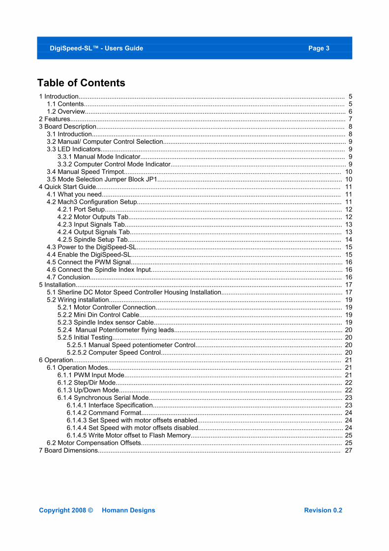
Table of Contents 1 Introduction................................................................................................................................................... 5
1.1 Contents................................................................................................................................................ 5 1.2 Overview................................................................................................................................................ 6
2 Features........................................................................................................................................................ 7 3 Board Description......................................................................................................................................... 8
3.1 Introduction............................................................................................................................................ 8 3.2 Manual/ Computer Control Selection..................................................................................................... 9 3.3 LED Indicators....................................................................................................................................... 9
3.3.1 Manual Mode Indicator................................................................................................................. 9 3.3.2 Computer Control Mode Indicator................................................................................................. 9
3.4 Manual Speed Trimpot........................................................................................................................ 10 3.5 Mode Selection Jumper Block JP1...................................................................................................... 10
4 Quick Start Guide....................................................................................................................................... 11 4.1 What you need.................................................................................................................................... 11 4.2 Mach3 Configuration Setup................................................................................................................. 11
4.2.1 Port Setup................................................................................................................................... 12 4.2.2 Motor Outputs Tab...................................................................................................................... 12 4.2.3 Input Signals Tab........................................................................................................................ 13 4.2.4 Output Signals Tab..................................................................................................................... 13 4.2.5 Spindle Setup Tab...................................................................................................................... 14
4.3 Power to the DigiSpeed-SL................................................................................................................. 15 4.4 Enable the DigiSpeed-SL.................................................................................................................... 15 4.5 Connect the PWM Signal..................................................................................................................... 16 4.6 Connect the Spindle Index Input.......................................................................................................... 16 4.7 Conclusion........................................................................................................................................... 16
5 Installation................................................................................................................................................... 17 5.1 Sherline DC Motor Speed Controller Housing Installation................................................................... 17 5.2 Wiring installation................................................................................................................................ 19
5.2.1 Motor Controller Connection....................................................................................................... 19 5.2.2 Mini Din Control Cable................................................................................................................ 19 5.2.3 Spindle Index sensor Cable........................................................................................................ 19 5.2.4 Manual Potentiometer flying leads............................................................................................. 20 5.2.5 Initial Testing............................................................................................................................... 20
5.2.5.1 Manual Speed potentiometer Control................................................................................. 20 5.2.5.2 Computer Speed Control.................................................................................................... 20
6 Operation.................................................................................................................................................... 21 6.1 Operation Modes................................................................................................................................. 21
6.1.1 PWM Input Mode........................................................................................................................ 21 6.1.2 Step/Dir Mode............................................................................................................................. 22 6.1.3 Up/Down Mode........................................................................................................................... 22 6.1.4 Synchronous Serial Mode........................................................................................................... 23
6.1.4.1 Interface Specification........................................................................................................ 23 6.1.4.2 Command Format............................................................................................................... 24 6.1.4.3 Set Speed with motor offsets enabled................................................................................ 24 6.1.4.4 Set Speed with motor offsets disabled................................................................................ 24 6.1.4.5 Write Motor offset to Flash Memory.................................................................................... 25
6.2 Motor Compensation Offsets............................................................................................................... 25 7 Board Dimensions...................................................................................................................................... 27
Copyright 2008 © Homann Designs Revision 0.2
DigiSpeed-SL™ - Users Guide Page 4
Index of Tables Table 1: Mode Select Jumper Block.............................................................................................................. 10Table 2: MiniDin Breakout Board Terminal Strip Connections........................................................................ 12Table 3: RJ-11 Index Sensor Pin out.............................................................................................................. 20Table 4: Mode Selection Jumpers.................................................................................................................. 21
Illustration IndexIllustration 1: DigiSpeed-SL Layout............................................................................................................... 8Illustration 2: Mach3 Port Setup...................................................................................................................... 12Illustration 3: Mach3 Motor Outputs Tab......................................................................................................... 13Illustration 4: Mach3 Input Signals Tab........................................................................................................... 13Illustration 5: Mach3 Output Signals Tab........................................................................................................ 14Illustration 6: Mach3 Spindle Setup Tab......................................................................................................... 15Illustration 7: Board mounted into enclosure................................................................................................... 17Illustration 8: DigiSpeed-SL Mounted Top View......................................................................................... 18Illustration 9: DigiSpeed showing cable routing.......................................................................................... 18Illustration 10: DigiSpeed-SL Mounted Side View...................................................................................... 18Illustration 11: PCB Layout and dimensions................................................................................................... 27Illustration 12: PCB Layout and Dimensions................................................................................................... 27
Copyright 2008 © Homann Designs Revision 0.2
DigiSpeed-SL™ - Users Guide Page 5
1 IntroductionThank you for purchasing Homann Designs' DigiSpeed-SL™ DC Motor Speed controller interface unit. The DigiSpeed-SL™ provides a way for controlling DC motor speed controllers that accept a 0-5Vdc, 0-10Vdc signal, or a manual speed potentiometer.
This document is a User's Guide that describes the operation of the DigiSpeed-SL™. The document contains information on how to use and integrate the board into your own systems.
1.1 Contents
The package received when ordering the DigiSpeed-SL™ contains the following:
• DigiSpeed-SL™ DC motor speed controller.• 4 x 0.1” jumpers.• 6 Pin minidin male-to-male cable.• MiniDin Breakout board.
* - Note These items are included with the DigiSpeed-SL™ Deal purchase.
Copyright 2008 © Homann Designs Revision 0.2
*** WARNING ***The KB Electronics DC speed controller circuit, and other similar speed controllers
as found in Asian imported mini lathes and mini mills are at mains voltage potential. This voltage is lethal. Do not attempt to do this conversion if you are not qualified
to do so. Confidence is no replacement for qualification!
If you feel that this project is beyond your abilities to SAFELY complete, we can install the unit for you. Please contact us for details
Please ensure you read the complete manual before attempting to install or use this device.
DigiSpeed-SL™ - Users Guide Page 6
1.2 OverviewThe DigiSpeed-SL DC motor controller is designed to allow computer CNC programs such as Mach2, TurboCNC and other CNC programs to primarily control the spindle speed of the Sherline CNC machines such as Mills and Lathes.
DigiSpeed-SL is designed primarily for use with KB Electronics style DC motor controllers, such as the KBIC-120. This is the type of controller found in the Sherline Mills and Lathes. DigiSpeed-SL will work with other types of DC motor controllers such as those found in the Asian imported mini lathes and Mills.
DigiSpeed-SL is designed to replace the manual speed setting potentiometer found in the SherlineDC motor controllers.
The form factor of the DigiSpeed-SL PCB has been designed for easy installation into the Sherline DC Motor Controller housing and other speed controller enclosures.
Copyright 2008 © Homann Designs Revision 0.2
DigiSpeed-SL™ - Users Guide Page 7
2 FeaturesThe main features of the DigiSpeed controller are;
• Controlled by a RISC Microchip micro-controller.• PCB
o FR4 Materialo Double Sided, Plated through holeso Silk-Screened on Component Sideo Solder Mask on Both Sides
• Small PCB footprint 84mm(L) x 28mm(W)• 5V dc 50mA power requirements.• Opto-isolation between the computer logic Voltages and the DC Speed controller voltages.• Maximum DC Speed controller voltage for the control supply of 24Vdc • Greater than 1000 steps from 0 to Max Speed.• Four methods to control motor speed.
o PWM - A low frequency PWM signal. (1Hz – 50Hz )o Step/Dir – Can be controlled like a stepper motoro Up/Down – Can be controlled via separate up/down inputso Synchronous Serial - Can be controlled by a serial Data, Clock interface
• Enable input to control to enable or inhibit the control voltage output.• All signals are Active Low to reduce the possibility of inadvertent spindle control• Programmable motor characteristics allow the DigiSpeed-SL to compensate for drag and
inefficiencies in the motor drive system.• Toggle switch to select Manual or Computer control• Multi color LED indicating the mode and state of the DigiSpeed-SL controller.• Uses standard Mini Din connector and cables to interface to the Controller.• RJ-11Connector for attaching a Sherline Tacho senor. It provides for the index signal to be feed to
the breakout board via the Mini Din cable. This feature tidies up the cable run cable. • Index Sensor Signal conditioning circuitry, providing a “clean” digital sensor signal.
Copyright 2008 © Homann Designs Revision 0.2
DigiSpeed-SL™ - Users Guide Page 8
3 Board Description
3.1 Introduction
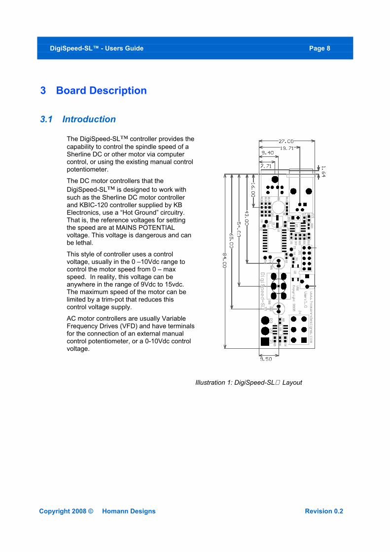
The DigiSpeed-SL™ controller provides the capability to control the spindle speed of a Sherline DC or other motor via computer control, or using the existing manual control potentiometer.
The DC motor controllers that the DigiSpeed-SL™ is designed to work with such as the Sherline DC motor controller and KBIC-120 controller supplied by KB Electronics, use a “Hot Ground” circuitry. That is, the reference voltages for setting the speed are at MAINS POTENTIAL voltage. This voltage is dangerous and can be lethal.
This style of controller uses a control voltage, usually in the 0 –10Vdc range to control the motor speed from 0 – max speed. In reality, this voltage can be anywhere in the range of 9Vdc to 15vdc. The maximum speed of the motor can be limited by a trim-pot that reduces this control voltage supply.
AC motor controllers are usually Variable Frequency Drives (VFD) and have terminals for the connection of an external manual control potentiometer, or a 0-10Vdc control voltage.
Copyright 2008 © Homann Designs Revision 0.2
Illustration 1: DigiSpeed-SL Layout
DigiSpeed-SL™ - Users Guide Page 9
The DigiSpeed-SL™ circuitry is essentially in two parts. One part contains low voltage logic level circuitry that includes a micro controller and interfaces to the PC via the parallel port. It is supplied by 5Vdc that is referenced to the PC parallel port ground. The other part of the DigiSpeed circuitry is connected to the DC Speed controller control circuitry. This part is at MAINS POTENTIAL.
The two parts of the circuitry are separated by opto-isolation. This ensures that the dangerous MAINS POTENTIAL voltages are kept away from the low level logic circuitry. The two parts of circuitry must never be connected together. If it happens, a catastrophic failure of the DigiSpeed-SL circuit and your PC will occur.
The
DigiSpeed-SL controller provides a control voltage in place of the control voltage provided by the manual speed control potentiometer. This voltage can be varied from 0V to 100% of the maximum control voltage by computer software.
There are 1023 steps from 0 to the maximum control voltage. If your maximum spindle speed is 6000 rpm, this effectively provides for a 6-rpm resolution in controlling spindle speed.
3.2 Manual/ Computer Control SelectionSelection between manual or computer control of the DigiSpeed-SL is done via the toggle switch mounted on the board. When the switch is toward the Mini Din connector, the DigiSpeed-SL is in Computer control. When positioned toward the three flying leads, the DigiSpeed-SL is in manual mode.
3.3 LED IndicatorsThe DigiSpeed-SL controller has two 5mm Mode indicator LEDs, one to indicate when Manual mode is selected, the other to indicate the mode and status of the computer interface.
3.3.1 Manual Mode IndicatorThe manual mode indicator is the LED positioned adjacent to the manual speed potentiometer. When the toggle switch is in the manual position, the LED will illuminate, indicating this mode is active.
3.3.2 Computer Control Mode IndicatorThe computer control mode indicator is the LED positioned towards the Mini Din connector. Regardless of the position of the toggle switch, the LED will illuminate in a number of ways, indicating the mode and state of the computer interface.
• LED Off – This indicates that there is no power supplied to the DigiSpeed-SL via the
Copyright 2008 © Homann Designs Revision 0.2
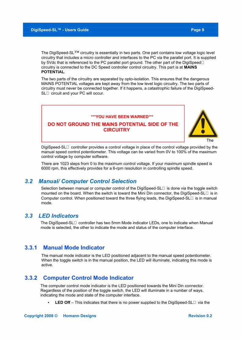
***YOU HAVE BEEN WARNED***
DO NOT GROUND THE MAINS POTENTIAL SIDE OF THE CIRCUITRY
DigiSpeed-SL™ - Users Guide Page 10
mini din connector
• Solid Colour – A Solid colour indicates that power is supplied to the DigiSpeed-SL via the Mini din connecter, and that the Enable line is NOT active. There are three solid colours indicating the input mode.
o RED – Indicates that the DigiSpeed-SL is in PWM input Mode.
o GREEN – Indicates that the DigiSpeed-SL is in either STEP/DIR or UP/DOWN input mode.
o YELLOW – Both red and green LEDs on indicates that the DigiSpeed-SL is in SYNCHRONOUS SERIAL input Mode
• Lazy RED Double Flash – Indicates that the DigiSpeed-SL is powered On, the Enable is active and the speed is zero. At this stage, hands should be kept clear of the spindle as it is ready to start.
• Fast RED Flash – Indicates that the DigiSpeed-SL is powered, the Enable is active and the speed is greater than zero. The spindle should be spinning as long as the set speed is large enough to over come the motor drag and inefficiencies. Of the motor drive train.
3.4 Manual Speed TrimpotThe DigiSpeed-SL has a small blue trimpot VR1, for adjusting the maximum manual speed of the motor, when in Manual mode.
VR1 allows the user to adjust the maximum speed of the motor when under manual mode so that is the same as the maximum speed when under computer control.
3.5 Mode Selection Jumper Block JP1The DigiSpeed-SL can operate in a number of modes, depending on the type of control signal that is provided by your CNC software. The mode is selected via the mode selection jumpers as shown in the picture below;
Jumper JP1 consists of a four jumpers . The labels for each jumper underside of the PCB, and described below.
Jumper Function when insertedMOT Removes the Motor compensation offsets
MS3 Not Used
MS2 Mode Select
MS1 Mode Select
+5V Not Used
Table 1: Mode Select Jumper Block
Copyright 2008 © Homann Designs Revision 0.2
DigiSpeed-SL™ - Users Guide Page 11
4 Quick Start GuideThis section is intended to allow you to quickly setup and verify the operation of your DigiSpeed-SL™ controller with Mach3. Initially, this will be done with the DigiSpeed-SL™ unit being connected to computer but not your Motor Drive. Once you are familiar with the operation of the DigiSpeed-SL's operation, it can then be connected to the motor drive.
The DigiSpeed-SL circuitry is essentially in two parts. One part contains low voltage logic level circuitry that includes a micro controller and interfaces to the PC via the parallel port. It is supplied by 5Vdc that is referenced to the PC parallel port ground. The other part of the DigiSpeed-SL circuitry is connected to the DC Speed controller control circuitry. This part is at MAINS POTENTIAL.
The quick start setup will verify the connection to the Microprocessor and logic side of the DigiSpeed-SL™ controller.
4.1 What you needTo get started, you need:
• DigiSpeed-SL™ controller.
• 6-pin Male to Male Minidin cable.
• MiniDin Breakout Board
• Breakout board or other mechanism for connecting the DigiSpeed-SL™ control lines to the Computer Printer port.
• A PC with a printer port and Mach3 installed and running.
Note, you may substitute the 6 pin mindin cable and Minidin breakout board with another cable, etc, depending on your wiring and CNC controller configuration.
The MiniDin breakout board connects to your CNC controller breakout board by wiring to the 6-pin screw terminal block on the MiniDin breakout board.
This quick start setup is done with the DigiSpeed-SL™ unit sitting on the bench and NOT connected to your Motor controller.
Mach3 controls the DigiSpeed-SL™ in PWM mode only. Therefore you need to remove any of the Mode select jumpers from jumper block JP1
4.2 Mach3 Configuration SetupThe example setup describes how Mach3 is configured for the DigiSpeed-SL™. Your configuration may differ depending on what Printer Port number you are using, and what pins in the port are connected to which DigiSpeed-SL™ pins.
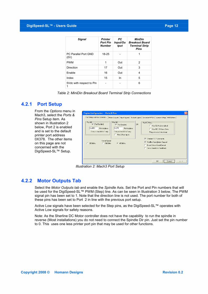
For this example, printer port 2 is being used with the port pins connected as shown in Table 2 below.
Notes:
1. It is advisable to use a breakout board between the Printer port and the DigiSpeed-SL™.
2. The 5V supply for the DigiSpeed-SL™ must be obtained from the breakout board, as it cannot be supplied from the printer port.
Copyright 2008 © Homann Designs Revision 0.2
DigiSpeed-SL™ - Users Guide Page 12
Signal Printer Port Pin Number
PC Input/Ou
tput
MinDin Breakout Board Terminal Strip
Pins
PC Parallel Port GND (0V)
18-25 - 1
PWM 1 Out 2
Direction 17 Out 3
Enable 16 Out 4
Index 15 In 5
5Vdc with respect to Pin 1
- - 6
Table 2: MiniDin Breakout Board Terminal Strip Connections
4.2.1 Port SetupFrom the Options menu in Mach3, select the Ports & Pins Setup item. As shown in Illustration 2 below, Port 2 is enabled and is set to the default printer port address 0X378. The other items on this page are not concerned with the DigiSpeed-SL™ Setup.
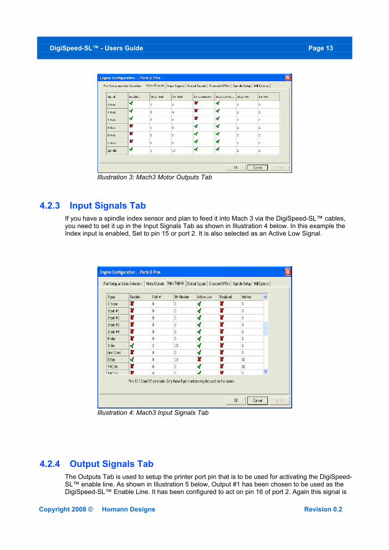
4.2.2 Motor Outputs TabSelect the Motor Outputs tab and enable the Spindle Axis. Set the Port and Pin numbers that will be used for the DigiSpeed-SL™ PWM (Step) line. As can be seen in Illustration 3 below, The PWM signal pin has been set to 1. Note that the direction line is not used. The port number for both of these pins has been set to Port 2 in line with the previous port setup.
Active Low signals have been selected for the Step pins, as the DigiSpeed-SL™ operates with Active Low signals for safety reasons.
Note: As the Sherline DC Motor controller does not have the capability to run the spindle in reverse (Most installations) you do not need to connect the Spindle Dir pin. Just set the pin number to 0. This uses one less printer port pin that may be used for other functions.
Copyright 2008 © Homann Designs Revision 0.2
Illustration 2: Mach3 Port Setup
DigiSpeed-SL™ - Users Guide Page 13
4.2.3 Input Signals TabIf you have a spindle index sensor and plan to feed it into Mach 3 via the DigiSpeed-SL™ cables, you need to set it up in the Input Signals Tab as shown in Illustration 4 below. In this example the Index input is enabled, Set to pin 15 or port 2. It is also selected as an Active Low Signal.
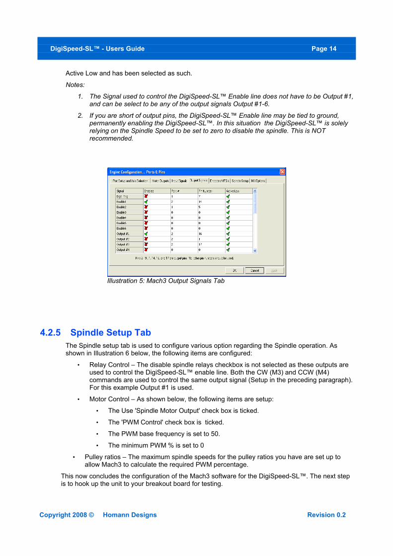
4.2.4 Output Signals TabThe Outputs Tab is used to setup the printer port pin that is to be used for activating the DigiSpeed-SL™ enable line. As shown in Illustration 5 below, Output #1 has been chosen to be used as the DigiSpeed-SL™ Enable Line. It has been configured to act on pin 16 of port 2. Again this signal is
Copyright 2008 © Homann Designs Revision 0.2
Illustration 3: Mach3 Motor Outputs Tab
Illustration 4: Mach3 Input Signals Tab
DigiSpeed-SL™ - Users Guide Page 14
Active Low and has been selected as such.
Notes:
1. The Signal used to control the DigiSpeed-SL™ Enable line does not have to be Output #1, and can be select to be any of the output signals Output #1-6.
2. If you are short of output pins, the DigiSpeed-SL™ Enable line may be tied to ground, permanently enabling the DigiSpeed-SL™. In this situation the DigiSpeed-SL™ is solely relying on the Spindle Speed to be set to zero to disable the spindle. This is NOT recommended.
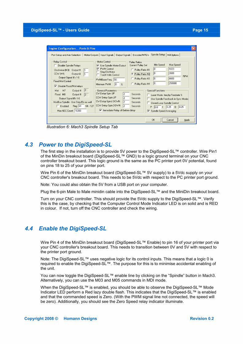
4.2.5 Spindle Setup TabThe Spindle setup tab is used to configure various option regarding the Spindle operation. As shown in Illustration 6 below, the following items are configured:
• Relay Control – The disable spindle relays checkbox is not selected as these outputs are used to control the DigiSpeed-SL™ enable line. Both the CW (M3) and CCW (M4) commands are used to control the same output signal (Setup in the preceding paragraph). For this example Output #1 is used.
• Motor Control – As shown below, the following items are setup:
• The Use 'Spindle Motor Output' check box is ticked.
• The 'PWM Control' check box is ticked.
• The PWM base frequency is set to 50.
• The minimum PWM % is set to 0
• Pulley ratios – The maximum spindle speeds for the pulley ratios you have are set up to allow Mach3 to calculate the required PWM percentage.
This now concludes the configuration of the Mach3 software for the DigiSpeed-SL™. The next step is to hook up the unit to your breakout board for testing.
Copyright 2008 © Homann Designs Revision 0.2
Illustration 5: Mach3 Output Signals Tab
DigiSpeed-SL™ - Users Guide Page 15
4.3 Power to the DigiSpeed-SLThe first step in the installation is to provide 5V power to the DigiSpeed-SL™ controller. Wire Pin1 of the MinDin breakout board (DigiSpeed-SL™ GND) to a logic ground terminal on your CNC controller breakout board. This logic ground is the same as the PC printer port 0V potential, found on pins 18 to 25 of your printer port.
Wire Pin 6 of the MiniDin breakout board (DigiSpeed-SL™ 5V supply) to a 5Vdc supply on your CNC controller's breakout board. This needs to be 5Vdc with respect to the PC printer port ground.
Note: You could also obtain the 5V from a USB port on your computer.
Plug the 6-pin Male to Male minidin cable into the DigiSpeed-SL™ and the MiniDin breakout board.
Turn on your CNC controller. This should provide the 5Vdc supply to the DigiSpeed-SL™. Verify this is the case, by checking that the Computer Control Mode Indicator LED is on solid and is RED in colour. If not, turn off the CNC controller and check the wiring.
4.4 Enable the DigiSpeed-SL
Wire Pin 4 of the MiniDin breakout board (DigiSpeed-SL™ Enable) to pin 16 of your printer port via your CNC controller's breakout board. This needs to transition between 0V and 5V with respect to the printer port ground.
Note: The DigiSpeed-SL™ uses negative logic for its control inputs. This means that a logic 0 is required to enable the DigiSpeed-SL™. The purpose for this is to minimise accidental enabling of the unit.
You can now toggle the DigiSpeed-SL™ enable line by clicking on the “Spindle” button in Mach3. Alternatively, you can use the M03 and M05 commands in MDI mode.
When the DigiSpeed-SL™ is enabled, you should be able to observe the DigiSpeed-SL™ Mode Indicator LED perform a Red lazy double flash. This indicates that the DigiSpeed-SL™ is enabled and that the commanded speed is Zero. (With the PWM signal line not connected, the speed will be zero). Additionally, you should see the Zero Speed relay indicator illuminate.
Copyright 2008 © Homann Designs Revision 0.2
Illustration 6: Mach3 Spindle Setup Tab
DigiSpeed-SL™ - Users Guide Page 16
Note: Setting a speed value in Mach3 will have no effect as the PWM signal has not been connected to the DigiSpeed-SL™.
4.5 Connect the PWM Signal
Wire Pin 2 of the MiniDin breakout board (DigiSpeed-SL™ PWM) to pin 1 of the printer port via your CNC controller's breakout board.
You can now test that the PWM speed value is being received by the DigiSpeed-SL™. Set the spindle speed to zero typing it into the speed DRO, or entering the command 'S 0' into the MDI window .
Now Click on the “Spindle” button, or use the 'M03' command in MDI mode. You should be able to observe the DigiSpeed-SL™ Mode Indicator LED perform a Red lazy double flash. This indicates that the DigiSpeed-SL™ is enabled.
Now enter a spindle speed of 1000 into the DRO. You should now observe the DigiSpeed-SL™ Mode Indicator LED perform a continuous Red fast flash. This indicates that the DigiSpeed-SL™ is enabled and is generating an analog control voltage on the output.
Additionally, you should observe that the Zero Speed relay indicator has extinguished.
4.6 Connect the Spindle Index InputIf you are planning to use the Spindle Index sensor input, wire Pin 5 of the MiniDin breakout board (DigiSpeed-SL™ Index Sensor Input) to pin 15 of the printer port via your CNC controller's breakout board.
You may need to wait until you have connected the DigiSpeed-SL™ to your Motor speed controller before testing the Spindle Index input.
4.7 ConclusionYou should now have your DigiSpeed-SL™ operating correctly with Mach3. You are now ready to install the unit into your Motor Speed controller's enclosure, your CNC controller or a separate enclosure.
Copyright 2008 © Homann Designs Revision 0.2
DigiSpeed-SL™ - Users Guide Page 17
5 InstallationBefore attempting the installation please read the entire manual. If you are unsure of anything, do not do the installation. I am not responsible for damage or injury resulting from the installation or use of this device. If necessary get help from someone who is qualified for this type of work
TableTopMachineShop llc, http://www.tabletopmachineshop.com are distributors of the DigiSpeed-SL and can install the unit for you.
It is advisable to integrate the The DigiSpeed-SL with your control software before installing and connecting it to your Motor Controller. The unit is powered from a breakout board via the 6 pin din din cable. Therefore it is possible to test and become familiar with it's operation prior to connecting it to a motor controller.
The board has indicator LEDs that provide status of what is occurring. These can be used to assist in the integration.
The DigiSpeed-SL has been designed be mounted into a Sherline DC motor controller enclosure, but may be mounted into other enclosures. The hardware installation is dependent on what you are installing the DigiSpeed-SL into. The physical installation is first covered in the section below, followed by the electrical installation.
5.1 Sherline DC Motor Speed Controller Housing InstallationIf the DigiSpeed-SL™ is to be installed into a Sherline Motor speed controller housing, ensure that there are no inadvertent shorts between the controller and the DigiSpeed-SL™., as it is a tight fit.
The following images show the installation steps
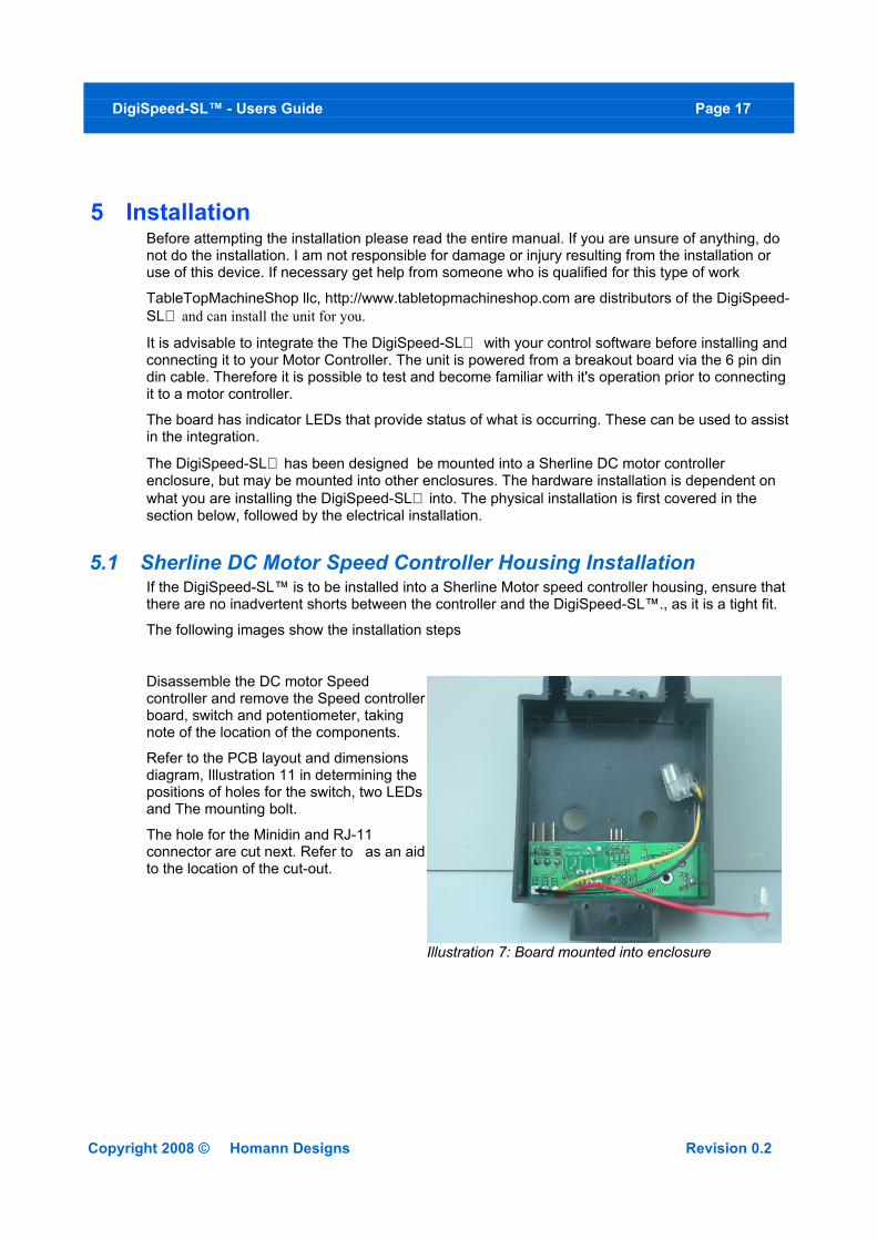
Disassemble the DC motor Speed controller and remove the Speed controller board, switch and potentiometer, taking note of the location of the components.
Refer to the PCB layout and dimensions diagram, Illustration 11 in determining the positions of holes for the switch, two LEDs and The mounting bolt.
The hole for the Minidin and RJ-11 connector are cut next. Refer to as an aid to the location of the cut-out.
Copyright 2008 © Homann Designs Revision 0.2
Illustration 7: Board mounted into enclosure
DigiSpeed-SL™ - Users Guide Page 18
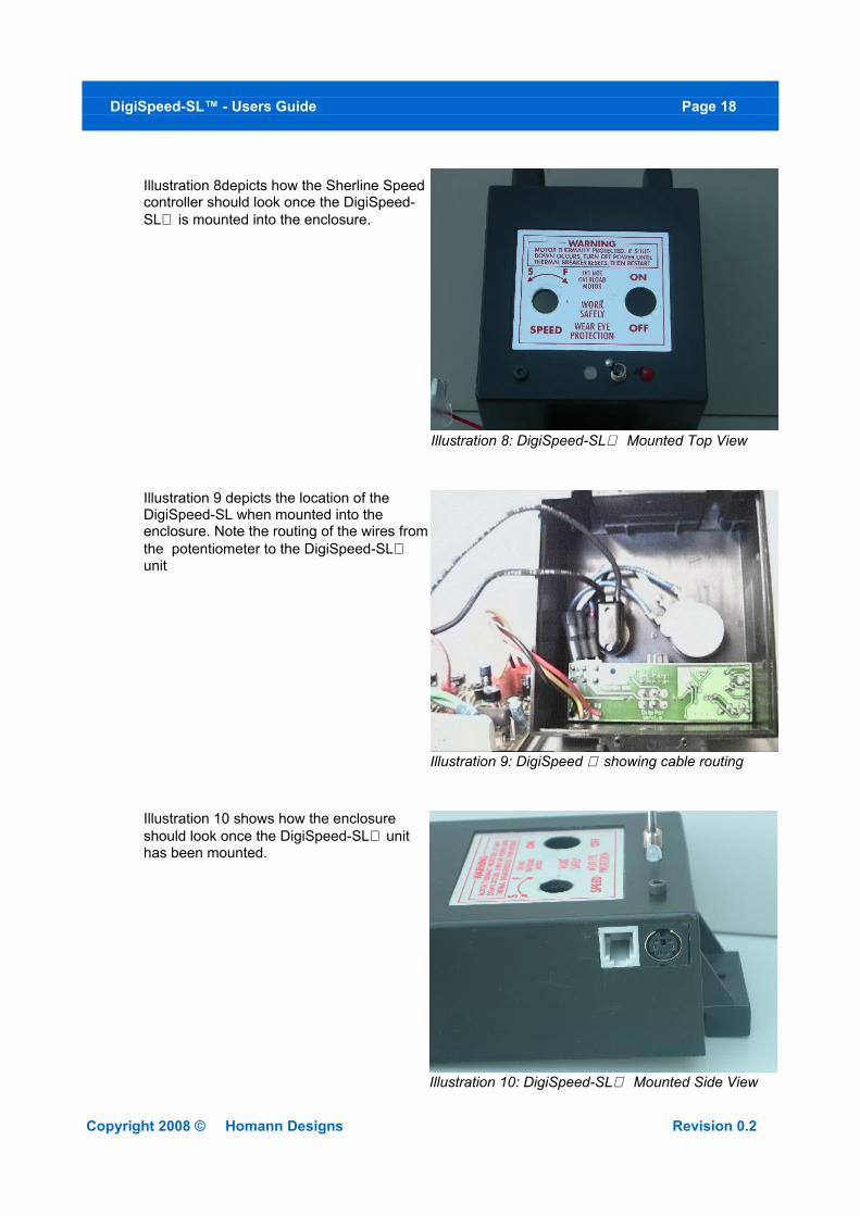
Illustration 8depicts how the Sherline Speed controller should look once the DigiSpeed-SL is mounted into the enclosure.
Illustration 9 depicts the location of the DigiSpeed-SL when mounted into the enclosure. Note the routing of the wires from the potentiometer to the DigiSpeed-SL unit
Illustration 10 shows how the enclosure should look once the DigiSpeed-SL unit has been mounted.
Copyright 2008 © Homann Designs Revision 0.2
Illustration 9: DigiSpeed showing cable routing
Illustration 10: DigiSpeed-SL Mounted Side View
Illustration 8: DigiSpeed-SL Mounted Top View
DigiSpeed-SL™ - Users Guide Page 19
5.2 Wiring installation
Once the DigiSpeed-SL controller is installed into a housing the following wiring is required.
5.2.1 Motor Controller ConnectionThe DigiSpeed-SL is connected to the motor controller via the three flying leads terminated with 6.3mm push-on terminals.
• The lead labeled P3 connects to the potentiometer positive voltage connector on the speed controller.
• The lead labeled P1 connects to the 0V potentiometer connector on the speed controller.
• The lead labeled P2 connects to the potentiometer control voltage on the speed controller.
These three flying leads plug into your speed controller in place of your existing manual speed potentiometer. Unless you are using a voltage isolation board these leads are at ***MAINS VOLTAGE POTENTIAL ***. They can cause serious injury or death. Do not connect any earthed test equipment to this terminal block as it is at mains potential.
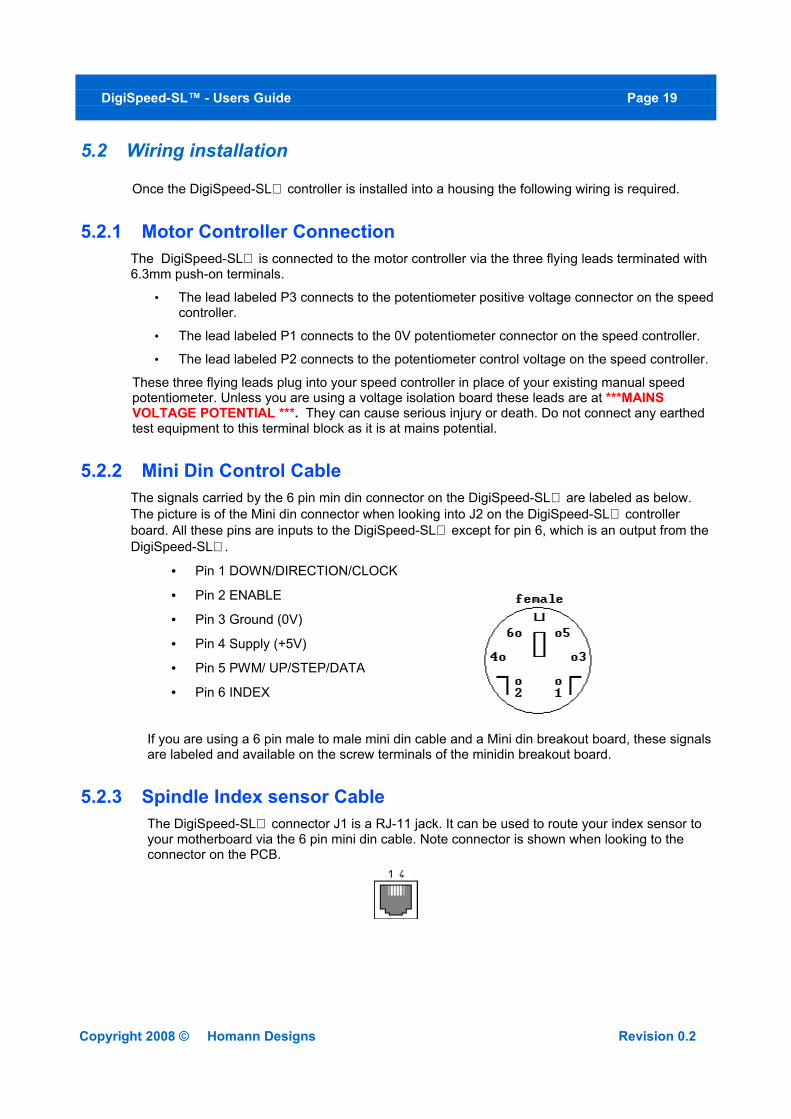
5.2.2 Mini Din Control CableThe signals carried by the 6 pin min din connector on the DigiSpeed-SL are labeled as below. The picture is of the Mini din connector when looking into J2 on the DigiSpeed-SL controller board. All these pins are inputs to the DigiSpeed-SL except for pin 6, which is an output from the DigiSpeed-SL.
• Pin 1 DOWN/DIRECTION/CLOCK
• Pin 2 ENABLE
• Pin 3 Ground (0V)
• Pin 4 Supply (+5V)
• Pin 5 PWM/ UP/STEP/DATA
• Pin 6 INDEX
If you are using a 6 pin male to male mini din cable and a Mini din breakout board, these signals are labeled and available on the screw terminals of the minidin breakout board.
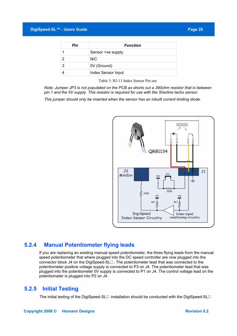
5.2.3 Spindle Index sensor CableThe DigiSpeed-SL connector J1 is a RJ-11 jack. It can be used to route your index sensor to your motherboard via the 6 pin mini din cable. Note connector is shown when looking to the connector on the PCB.
Copyright 2008 © Homann Designs Revision 0.2
DigiSpeed-SL™ - Users Guide Page 20
Pin Function1 Sensor +ve supply
2 N/C
3 0V (Ground)
4 Index Sensor Input
Table 3: RJ-11 Index Sensor Pin out
Note: Jumper JP3 is not populated on the PCB as shorts out a 390ohm resistor that is between pin 1 and the 5V supply. This resistor is required for use with the Sherline tacho sensor.
This jumper should only be inserted when the sensor has an inbuilt current limiting diode.
5.2.4 Manual Potentiometer flying leadsIf you are replacing an existing manual speed potentiometer, the three flying leads from the manual speed potentiometer that where plugged into the DC speed controller are now plugged into the connector block J4 on the DigiSpeed-SL. The potentiometer lead that was connected to the potentiometer positive voltage supply is connected to P3 on J4. The potentiometer lead that was plugged into the potentiometer 0V supply is connected to P1 on J4. The control voltage lead on the potentiometer is plugged into P2 on J4.
5.2.5 Initial TestingThe initial testing of the DigiSpeed-SL installation should be conducted with the DigiSpeed-SL
Copyright 2008 © Homann Designs Revision 0.2
DigiSpeed-SL™ - Users Guide Page 21
NOT connected to you computer or breakout board.
5.2.5.1 Manual Speed potentiometer Control1. Set the Auto/Manual speed control switch to the manual position, towards the
potentiometer, away from the MiniDin connector.
2. Turn the manual speed potentiometer fully counter clockwise.
3. Switch on the power to the motor controller. The spindle should not rotate. If anything appears wrong, immediately switch off the power to the motor controller.
4. Now slowly turn the potentiometer clockwise. The spindle should start to rotate until maximum speed is obtained.
5.2.5.2 Computer Speed Control.To test the DigiSpeed-SL control from Mach3:
1. Turn off the Motor Speed controller and the CNC controller .
2. Set the Auto/Manual speed control switch to the Auto position, towards the MiniDin Connector, away from the manual speed potentiometer.
3. Plug the 6 pin MiniDin connector into the DigiSpeed-SL unit and the breakout board.
4. Turn on the Motor Speed controller, then the CNC controller. Ensure that there is 5Vdc power applied to the DigiSpeed-SL. You can verify this by the Solid Red LED illuminated on the DigiSpeed-SL.
5. Run through the tests detailed in the Quick Start Guide section with the understanding that the spindle is not powered and operational.
Copyright 2008 © Homann Designs Revision 0.2
DigiSpeed-SL™ - Users Guide Page 22
6 Operation
6.1 Operation Modes
The DigiSpeed-SL™ has four operational modes, selected by jumpers MS1, MS2 in jumper block JP1. The selection of the modes is described below.
Mode MS1 MS2PWM Removed Removed
STEP/DIR Removed Installed
UP/DOWN Installed Installed
SERIAL Installed Removed
Table 4: Mode Selection Jumpers
The selection of the mode is done at power up initialization.
If the mode selection jumpers are modified after the unit is powered up, the new mode will not take effect until the power is cycled.
Each of the modes is discussed in detail below.
6.1.1 PWM Input ModeIn this mode the DigiSpeed-SL controller accepts an “Active Low” Pulse Width Modulation signal. The duty cycle of this signal represents 0 to 100% of maximum spindle speed.
The PWM signal period can be in the range of 2Hz to 50Hz. The optimum period is 5Hz. This will provide 1023 speed increments from 0 to 100% of maximum spindle speed.
The mini-din pins used for this mode are;• Pin 2 ENABLE
• Pin 3 Ground (0V)
• Pin 4 Supply (+5V)
• Pin 5 PWM
With +5V is supplied to the DigiSpeed-SL module, the LED will be a solid Red color when the ENABLE signal is not active.
When the ENABLE line is set active (0v), and no PWM signal is present, the LED will be a Red slow double flash. This indicates that the spindle is active but the speed is set to 0 %. Then, when a PWM signal is present with an active ENABLE line, the LED will be a fast continuous flash, indicating that the spindle is active and the speed is set to a value greater than 0 %.
Note: If a PWM signal is present, but the ENABLE input is inactive. The LED will be a Red slow double flash. As soon as the Enable is made active, the Spindle will start, setting the speed to the commanded PWM value.
Copyright 2008 © Homann Designs Revision 0.2
DigiSpeed-SL™ - Users Guide Page 23
6.1.2 Step/Dir ModeIn this mode the DigiSpeed-SL controller accepts an “Active Low” STEP signal, along with an increase (0v) or decrease (+5V) DIR signal.
With +5V is supplied to the DigiSpeed-SL module, the LED will be a solid Green color when the ENABLE signal is not active.
The DigiSpeed-SL controller keeps an internal speed counter that retains the current speed value for as long as power (+5V) is supplied to the module. On power up the speed counter is set to 0. The counter is limited to a range of 0 to 1023. And steps that try to count outside this range will be ignored with the speed counter being limited.
On each high to lo transition of the STEP line the speed counter will be updated. If the DIR line is low, the speed counter will be incremented. If the DIR line is high, the speed counter will be decremented.
The speed counter is operational regardless of the state of the Enable signal. Therefore, if the Step line is active while the ENABLE line is not active, the speed counter will be updated. This allows the speed of the DigiSpeed-SL to be set into the speed counter before the spindle is turned on via the ENABLE line.
This feature is analogous to the S word in the G-Code language. For example, if the G-Code sets the speed by, say, S1000, the PC CNC controller software can immediately update the speed counter in the DigiSpeed-SL controller. Then when the G-Code turns on the spindle with the M03 command, by making the ENABLE signal active, the spindle will start with the speed set to previously set speed counter value.
As part of the software initialization for any PC CNC controller software that uses the DigiSpeed-SL in STEP/DIR mode, the software should on initialization, issue at least 1023 steps with the DIR signal set to decrease speed (+5v). This will ensure that the speed counter in the DigiSpeed-SL is set to zero. This procedure should also be done whenever the PC CNC software and the DigiSpeed-SL speed counter get out of synchronization.
The mini-din pins used for this mode are;• Pin 1 DIR
• Pin 2 ENABLE
• Pin 3 Ground (0V)
• Pin 4 Supply (+5V)
• Pin 5 STEP
6.1.3 Up/Down ModeIn this mode the DigiSpeed-SL controller accepts “Active Low” UP and DOWN signals.
With +5V is supplied to the DigiSpeed-SL module, the LED will be a solid Green color when the ENABLE signal is not active.
The DigiSpeed-SL controller keeps an internal speed counter that retains the current speed value for as long as power (+5V) is supplied to the module. On power up the speed counter is set to 0. The counter is limited to a range of 0 to 1023. And steps that try to count outside this range will be ignored with the speed counter being limited.
.On each high to lo transition of the UP line, the speed counter will be incremented. On each high
Copyright 2008 © Homann Designs Revision 0.2
DigiSpeed-SL™ - Users Guide Page 24
to lo transition of the DOWN line, the speed counter will be decremented.
The speed counter is operational regardless of the state of the Enable signal. Therefore, if the UP or DOWN line is active while the ENABLE line is not active, the speed counter will be updated. This allows the speed of the DigiSpeed-SL to be set into the speed counter before the spindle is turned on via the ENABLE line.
This feature is analogous to the S word in the G-Code language. For example, if the G-Code sets the speed by, say, S1000, the PC CNC controller software can immediately update the speed counter in the DigiSpeed-SL controller. Then when the G-Code turns on the spindle with the M03 command, by making the ENABLE signal active, the spindle will start with the speed set to previously set speed counter value.
As part of the software initialization for any PC CNC controller software that uses the DigiSpeed-SL in UP/DOWN mode, the software should on initialization, issue at least 1023 DOWN steps. This will ensure that the speed counter in the DigiSpeed-SL is set to zero. This procedure should also be done whenever the PC CNC software and the DigiSpeed-SL speed counter get out of synchronization.
The mini-din pins used for this mode are;• Pin 1 DOWN
• Pin 2 ENABLE
• Pin 3 Ground (0V)
• Pin 4 Supply (+5V)
• Pin 5 UP
6.1.4 Synchronous Serial ModeIn this mode the DigiSpeed-SL controller accepts commands via a synchronous serial interface
With +5V is supplied to the DigiSpeed-SL module, the LED will be a solid Yellow color when the ENABLE signal is not active.
The mini-din pins used for this mode are;• Pin 1 CLOCK
• Pin 2 ENABLE
• Pin 3 Ground (0V)
• Pin 4 Supply (+5V)
• Pin 5 DATA
There are three commands that can be used to control the DigiSpeed-SL controller;
• Set Speed with motor offsets enabled
• Set Speed with motor offsets disabled
• Write Motor offset to Flash memory
6.1.4.1 Interface SpecificationThe synchronous serial interface consists of three signals, an Enable signal (Pin 2), a data signal (pin 5) and a clock signal (pin 1).
The Enable signal is an active low signal. 0 volts on this line enables the analog voltage output.
Copyright 2008 © Homann Designs Revision 0.2
DigiSpeed-SL™ - Users Guide Page 25
The serial interface is still operational, even though the Enable line is not active.
The serial data expects the LSB of a byte first.
The Data is clocked into the DigiSpeed-SL on a negative transition of the clock signal. The maximum speed of the clock signal is 10KHz.
If there is no activity on the clock signal for 200ms, the serial interface is reset. This is a safety feature that also allows for the serial interface to automatically re-synchronize to a broken data stream.
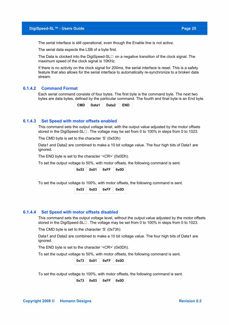
6.1.4.2 Command FormatEach serial command consists of four bytes. The first byte is the command byte. The next two bytes are data bytes, defined by the particular command. The fourth and final byte is an End byte.
CMD Data1 Data2 END
6.1.4.3 Set Speed with motor offsets enabledThis command sets the output voltage level, with the output value adjusted by the motor offsets stored in the DigiSpeed-SL. The voltage may be set from 0 to 100% in steps from 0 to 1023.
The CMD byte is set to the character ‘S’ (0x53h)
Data1 and Data2 are combined to make a 10 bit voltage value. The four high bits of Data1 are ignored.
The END byte is set to the character ‘<CR>’ (0x0Dh).
To set the output voltage to 50%, with motor offsets, the following command is sent.0x53 0x01 0xFF 0x0D
To set the output voltage to 100%, with motor offsets, the following command is sent.0x53 0x03 0xFF 0x0D
6.1.4.4 Set Speed with motor offsets disabledThis command sets the output voltage level, without the output value adjusted by the motor offsets stored in the DigiSpeed-SL. The voltage may be set from 0 to 100% in steps from 0 to 1023.
The CMD byte is set to the character ‘S’ (0x73h)
Data1 and Data2 are combined to make a 10 bit voltage value. The four high bits of Data1 are ignored.
The END byte is set to the character ‘<CR>’ (0x0Dh).
To set the output voltage to 50%, with motor offsets, the following command is sent.0x73 0x01 0xFF 0x0D
To set the output voltage to 100%, with motor offsets, the following command is sent.0x73 0x03 0xFF 0x0D
Copyright 2008 © Homann Designs Revision 0.2

DigiSpeed-SL™ - Users Guide Page 26
6.1.4.5 Write Motor offset to Flash MemoryThis command writes a motor offset into the DigiSpeed-SL. There are 64 offsets that cover the 1024 voltage settings. The offset is added to the voltage setting before being converted to an analog voltage.
If the resultant voltage setting exceeds 1023, it will be limited to 1023.
Each offset value covers 16 voltage settings. Offset 0 is added to voltage settings 0 to 15. Offset 1 is added to voltage settings 16 to 31, etc.
The CMD byte is set to the character ‘S’ (0x57h)
Data1 is the Motor Offset index. The valid range for the index is 0 x00h to 0x3Fh.
Data2 is the Motor Offset Value for the particular index. The valid range for the offset value is 0 x00h to 0xFFh.
The END byte is set to the character ‘<CR>’ (0x0Dh).
To set the motor offset at index 4 to 15, the following command is sent.0x57 0x04 0x0F 0x0D
The following motor offsets are pre-programmed into the DigiSpeed-SL. These are the offsets used for a DC motor setup on a Taig CNC Mill.
Low Nibble
High Nibble
x0 x1 x2 x3 x4 x5 x6 x7 x8 x9 xA xB xC xD xE xF
0x 88 86 84 82 80 78 76 75 73 71 69 67 65 64 62 60
1x 59 57 55 53 51 50 49 48 46 44 43 42 41 40 38 36
2x 34 32 30 28 26 25 24 23 22 20 18 17 16 15 13 12
3x11 10 8 7 6 5 4 3 2 1 0 0 0 0 0 0
6.2 Motor Compensation Offsets
The DigiSpeed-SL™ contains programmable offsets. The offsets are added to the commanded output voltage value. The purpose of these offsets is to add a voltage to the output so as to overcome non-linearities in the speed curve due to drag and inefficiencies in the motor drive system.
Most low cost motor controllers will benefit from having the offsets applied. Motor controllers with internal compensation may not need the application of the DigiSpeed-SL™ offsets.
The DigiSpeed-SL™ is capable of generating 1024 separate speed increments between 0 and
Copyright 2008 © Homann Designs Revision 0.2

DigiSpeed-SL™ - Users Guide Page 27
100% . There are 64 programmable offset values. Each offset covers a block of 8 speed increments. Each compensation value may range between 0 and 255.
When selected, the final output voltage is calculated as;
Vout = PWM duty cycle percentage X 1023 + compensation value.
The Vout value is then limited to 1023 or less.
The MOT jumper controls whether the programmed motor offset compensation values are applied. When inserted the MOT jumper on Jumper Block JP1 disables the motor compensation offsets from being added to the commanded speed.
Copyright 2008 © Homann Designs Revision 0.2
DigiSpeed-SL™ - Users Guide Page 28
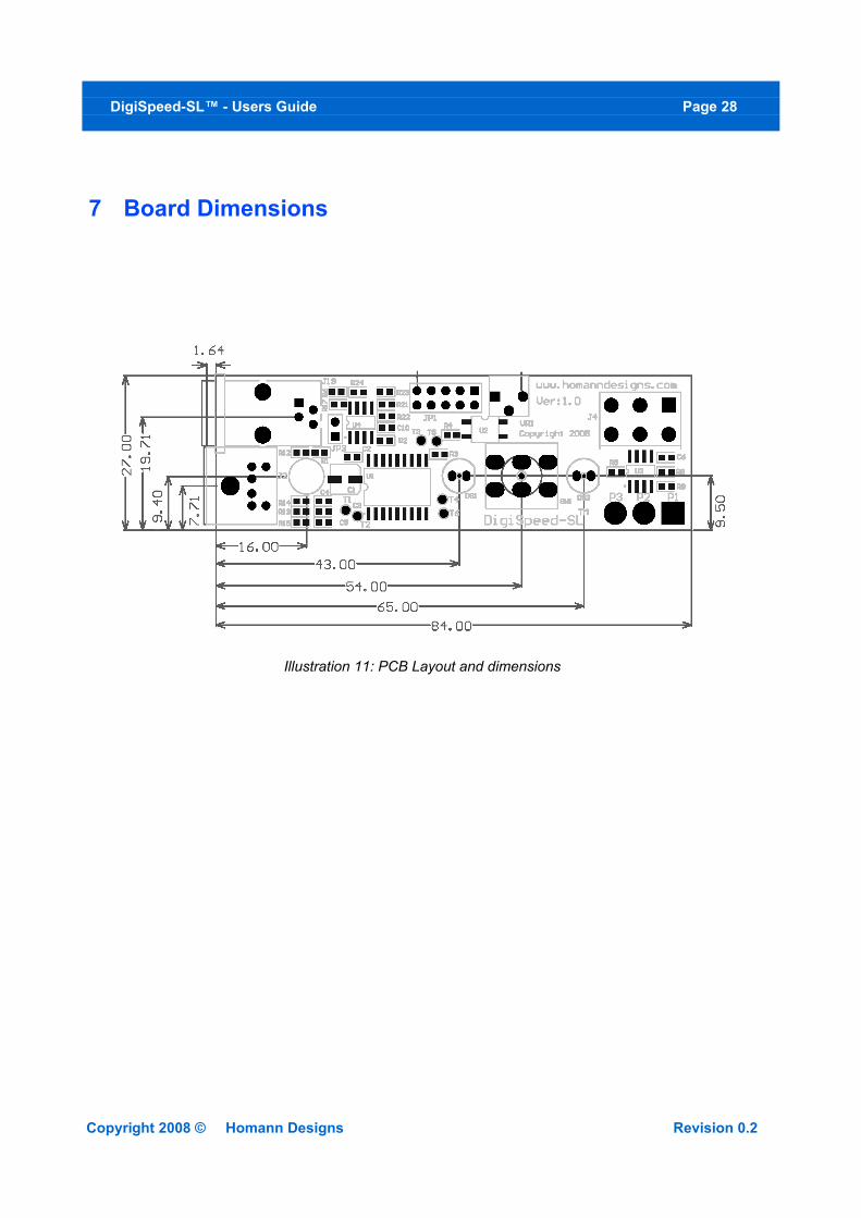
7 Board Dimensions
Copyright 2008 © Homann Designs Revision 0.2
Illustration 11: PCB Layout and dimensions