Embed Size (px)
Citation preview

MULTIZONE PAGING AND SOURCE SELECTION SYSTEM
INSTALLATION AND OPERATION MANUAL
DigiPage

1. Save the carton and packing material even if the equipment hasarrived in good condition. Should you ever need to ship the unit, use only the original factory packing.
2. Read all documentation before operating your equipment. Retain all documentation for future reference.
3. Follow all instructions printed on unit chassis for proper operation.
4. Do not spill water or other liquids into or on the unit, or operate theunit while standing in liquid.
5. Make sure power outlets conform to the power requirements listed on the back of the unit.
6. Do not use the unit if the electrical power cord is frayed or broken.The power supply cords should be routed so that they are not likely to be walked on or pinched by items placed upon or against them,paying particular attention to cords and plugs, conveniencereceptacles, and the point where they exit from the appliance.
7. Always operate the unit with the AC ground wire connected to theelectrical system ground. Precautions should be taken so that themeans of grounding of a piece of equipment is not defeated.
8. Mains voltage must be correct and the same as that printed on therear of the unit. Damage caused by connection to improper ACvoltage is not covered by any warranty.
9. Have gain controls on amplifiers turned down during power-up toprevent speaker damage if there are high signal levels at theinputs.
10. Power down & disconnect units from mains voltage before makingconnections.
11. Never hold a power switch in the “ON” position if it won’t staythere itself!
12. Do not use the unit near stoves, heat registers, radiators, or other heat producing devices
13. Do not block fan intake or exhaust ports. Do not operate equipment on a surface or in an environment which may impedethe normal flow of air around the unit, such as a bed, rug,weathersheet, carpet, or completely enclosed rack. If the unit is used in an extremely dusty or smoky environment, the unit should be periodically “blown free” of foreign matter.
14. Do not remove the cover. Removing the cover will expose you topotentially dangerous voltages. There are no user serviceableparts inside.
15. Do not drive the inputs with a signal level greater than thatrequired to drive equipment to full output.
16. Do not connect the inputs / outputs of amplifiers or consoles toany other voltage source, such as a battery, mains source, orpower supply, regardless of whether the amplifier or console isturned on or off.
17. Do not run the output of any amplifier channel back into anotherchannel’s input. Do not parallel- or series-connect an amplifier output with any other amplifier output.
Australian Monitor Inc is not responsible for damage toloudspeakers for any reason.
18. Do not ground any red (“hot”) terminal. Never connect a “hot” (red) output to ground or to another “hot” (red) output!
19. Non-use periods. The power cord of equipment should be unpluggedfrom the outlet when left unused for a long period of time.
20. Service Information Equipment should be serviced by qualifiedservice personnel when:
A. The power supply cord or the plug has been damaged.B. Objects have fallen, or liquid has been spilled into the
equipmentC. The equipment has been exposed to rainD. The equipment does not appear to operate normally,
or exhibits a marked change in performanceE. The equipment has been dropped, or the enclosure damaged.
IMPORTANT SAFETY INFORMATION
THIS SAFETY INFORMATION IS OF A GENERAL NATURE AND MAY BE SUPERSEDED BY INSTRUCTIONS CONTAINED WITHIN THIS MANUAL

DIGIPAGE INSTALLATION & OPERATION MANUAL PAGE 3
INTRODUCTION AND CONTENTS
The Australian Monitor Installation Series DigiPage is a 3 rack unit multizone paging and source selection system that offersunprecedented flexibility for multizone paging & source routingapplications.
Six program inputs and one dedicated local mic/line input are availableto each of eight zone outputs. With LED indication for program/localinput selection, zone output level, paging enable/disable and networkbusy LED, the DigiPage provides extensive status indication to the user.
The DigiPage is also expandable to 16 zones via a simple link cable to a second unit. Paging stations are available in 8 zone and 16 Zonemodels allowing paging into any individual zone, any combination ofzones or All Call. Remote control panels are also available, allowingsource selection and volume control from within each remote zone.Both the Paging stations and remote control panels connect via aninexpensive and industry standard CAT5 cable network. An overallpriority input is also provided for emergency or evacuation signals.
The DigiPage is powered by an (included) external plug-pack powersupply or via 24VDC. The DigiPage is an incredibly versatile and wellfeatured product that provides a simple solution to the complexapplications of multizone paging and source routing.
We thank you for choosing Australian Monitor Installation Series and as with all our products, the DigiPage offers clever features and is contractor friendly.
INTRODUCTION 3
FRONT PANEL 4
REAR PANEL 6
INSTALLATION 8
DIMENSIONS 11
SETUP 12
TROUBLESHOOTING 13
LINKING TWO DIGIPAGE SYSTEMS 14
OPERATION 15
PAGING STATION 16
REMOTE CONTROL PANEL 18
BLOCK DIAGRAM 20
ACCESSORIES 21
SPECIFICATIONS 22
This symbol is intended to alert the user to the presence
of uninsulated “dangerous voltage” within the product’s
enclosure that may be of sufficient magnitude to
constitute a risk of electric shock to persons.
This symbol is intended to alert the user to the presence
of important operation and maintenance (servicing)
instructions in the literature accompanying the appliance.
To prevent electric shock do not use this (polarised) plug
with an extension cord, receptacle or other outlet unless
the blades can be fully inserted to prevent blade exposure.
To prevent electric shock, match wide blade of plug to
wide slot, fully insert.
Caution:
AUS, EUR, USACopyright 27th May 2003
Rev A: 27th May 2003Rev B: 11th Aug 2004Rev C: 13th Jan 2006

PAGE 4 DIGIPAGE INSTALLATION & OPERATION MANUAL
FRONT PANEL
1
6
7
8
9
10
5
11
2
3
4a
5 6
Expanded View
4 4b

DIGIPAGE INSTALLATION & OPERATION MANUAL PAGE 5
FRONT PANEL
The controls detai led below (1-12) apply to each output zone, as indicated by ZONE 1 to ZONE 8 on the front panel .
LOCAL
This switch will turn the local input on or off in the zone. The local input is forexclusive use in the zone (eg Local Input 3to Zone 3). The Local switch operatesindependently of the program switches.The local input can be mic or line; see Rearpanel on page 6.
PROG 1–6
This series of program switches (PROG 1– PROG 6) allows the connectedprogram sources to be switched to thedesired zone. Program inputs may be mic or line, see Rearpanel on page 6.The program sources can be selectedindividually, or multiple program sourcescan be mixed together. Operation is as follows:
Select one program sourcePress momentarilyAdd another program sourcePress and hold for 2 secsDeselect program sourcePress and hold for 2 secsTurn off all program sourcesPress Prog Off
PROG OFF
This switches program off in the desired zone.
MASTER 1–8
4a Up/Down
These buttons increase and decrease the zone output level.4bMaster volume control position indication.
NOTE: This is NOT a signal levelmeter. It indicates relativevolume position.
PAGE ENABLE
This switch allows the zone to be includedin or isolated from the paging stations. You may want to do this when a zone is foran area such as a function room thatoccasionally may need to be isolated frompaging. When this button is pressed, theadjacent green indicator lights, indicatingthat the zone is able to receive paging.
TREBLE
The treble control has 9dB of cut or boostat 10kHz. The treble control affects theentire zone.
NOTE: That ‘center’ is to the left (9 o’clock), not the top (12 o’clock).
BASS
The bass control has 12dB of cut or boostat 100Hz. The bass control affects theentire zone.
NOTE: That ‘center’ is to the left (9 o’clock), not the top (12 o’clock).
LOCAL
This control adjusts the level of the localinput into the zone.
PROG
This control adjusts the overall level of allprogram sources into the zone.
NOTE: To balance the differinglevels of each program input, theprogram trim controls on the rearpanel should be used (see rearpanel and setup sections)
PAGE
This control adjusts the paging mic level into the zone.
BUSY
This LED indicates that the controlnetwork is busy in this zone. The zone is currently being paged or adjusted.
Located at the right-hand end of the unit,these controls affect all zones.
ON
This LED indicates there is power to the unit.
NOTE: When 24VDC emergencypower is supplied this LED willalways be on.
POWER
This switches power from the powersupply (included).
NOTE: When 24VDC emergencypower is supplied, the unit is onregardless of the switch position
5
6
7
8
9
10
11
12
13
1
2
3
4
☛
☛
☛
☛
☛
☛

PAGE 6 DIGIPAGE INSTALLATION & OPERATION MANUAL
REAR PANEL
8 7 6 5 4 3
1 2

DIGIPAGE INSTALLATION & OPERATION MANUAL PAGE 7
REAR PANEL
LOCAL 1–8 INPUT SECTION
LINE The pair of RCA sockets acceptsunbalanced line level inputs. Stereosignals are internally summed to mono.MIC/LINE The switch selects thesensitivity of the balanced XLR input ONLY.Switch in: microphone levelSwitch out: line levelThe XLR socket accepts balancedmicrophone or line level signals.
NOTE: The Local Input is routedonly to the same numbered zoneoutput and is switched on or offvia the front panel or remotecontrol panel.
PROG 1–6 INPUT SECTION
LINE The pair of RCA sockets acceptsunbalanced line level inputs. Stereosignals are internally summed to mono.MIC The XLR socket accepts balancedmicrophone level signals.PROG GAIN The trimpot controls the input gain of BOTH the balanced andunbalanced program inputs. In a Master/Slave configuration, thesealso control program linked inputs. (see Linking Section)
ZONE OUTPUTS
There is a balanced XLR line level outputfor each zone.
NOTE: If connecting to anunbalanced input, the negativepin (3) should not be connected toground but left floating.NOTE: When operating as a slave unit, outputs labelled 1 to 8will correspond to zones 9 to 16,respectively.(see Linking Section)
EUROBLOCK CONNECTOR
24V DC / GROUND This input pair is forconnection to a 24VDC emergency powersupply and is not switched by the frontpanel power switch.
NOTE: The 24V DC input does notprovide a trickle-charge facility.
ALERT/EVAC/COMMON Theseconnections are used to trigger theinternal tones. Only one tone can betriggered at a time. Triggering occurs byconnecting the ALERT or EVAC terminal to COMMON.GROUND/SUM IN This is an unbalancedline level input which may be used foremergency priority signals. It feeds alloutputs independent of output levelsettings and page enable status.
NOTE: Signal on the SUM IN willcause other signals to be muted.
SUM INPUT LEVEL This recessed trimpotsets the level of the sum input.TONE GEN OUTPUT LEVEL This recessedtrim pot controls the output level of thetones and the chime.
CAT 5 RUN 1–4
These RJ45 inputs accept the CAT5 cablescoming from the paging microphonestations and the remote control panels.See page 10 for more information.
NOTE: These are NOT Ethernet connections.NOTE: Connecting anddisconnecting these inputs while the unit is on may causethe unit to lock up requiringsystem power to be cycled.
PROG LINKS
These RJ45 sockets allow linking of the program sources when using aMaster/Slave configuration. (see Linking Section)
NOTE: These are NOT Ethernet connections.
DATA LINK
This socket is used to link two units in a Master/Slave configuration. (see Linking Section)
NOTE: These are NOT Ethernet connections.
MASTER/SLAVE
This switch is used when linking 2 units inMaster/Slave configuration. (see LinkingSection)
POWER IN VAC
This 2.1mmx5.5mm power socket accepts the 20VAC power supply provided with the unit.
1
2
4
35
6
7
8
☛
☛
☛
☛☛
☛
☛
☛
☛
FEMALE XLR
PIN 1GND
PIN 2HOT
+
PIN 3COLD
-
MALE XLR
PIN 2HOT
+
PIN 1GND
PIN 3COLD
_
9

INSTALLATION
OVERVIEW
The DigiPage features extensive flexibility in the range of input sourcesthat it can accommodate. In addition, the zone outputs may be used tofeed power (booster) amplifiers, mixers, mixer amplifiers etc. It istherefore important to think about the interfacing of the DigiPage withthe other equipment if optimum performance is to be achieved. Use theBack Panel and Specifications sections of this manual to assist withsystem design.
NOTE: XLR CONFIGURATION
When wiring the outputs on the DigiPage as unbalanced, Pin2 shouldbe used as hot and Pin1 as ground. Pin3 should be left open and NOTshorted to Pin1.
NOTE: If installing and terminating CAT5 cable is new to you, please take note of the various points thatfollow. As the CAT5 cabling for the DigiPage carriesvoltage, damage could occur if your pin-pinconnections are not made correctly.
CABLE INSTALLATION FOR PAGING STATIONS AND REMOTE PANELS
Four RJ45 ports (labeled CAT 5 RUN 1-4) are provided for connection to the DigiPage Zone Paging Stations and Remote wall panels. The four ports allow for easy cable infrastructure, as CAT5 runs can be of differing lengths depending on the installation and the number of units connected.
In planning the installation, the following rules apply:• Up to 4 Paging Stations, remote control panels or combinations
• The following table indicates the maximum distance allowable for a CAT5 run on a single port.
• For greater distances or more units, see page 10• The last unit on a run must be terminated. This is done by moving
a jumper on the paging station or remote unit. See ‘Paging Station’on pages 16-17 or ‘Remote Control Panel’ on pages 18-19.
NOTE: These are NOT Ethernet connections.
COMBINATION OF DEVICES MAX DISTANCEON SINGLE CAT5 RUN TO END UNIT (M/FT)
1 x PAGING STATION 250m/820ft
2 x PAGING STATIONS 125m/410ft
3 x PAGING STATIONS 80m/260ft
4 x PAGING STATIONS 62.5m/205ft
1 x WALLPLATE 500m/1640ft
2 x WALLPLATES 250m/820ft
3 x WALLPLATES 165m/540ft
4 x WALLPLATES 125m/410ft
1 x PAGING STATION & 1 x WALLPLATE 165m/540ft
1 x PAGING STATION & 2 x WALLPLATES 125m/410ft
1 x PAGING STATION & 3 x WALLPLATES 100m/330ft
2 x PAGING STATIONS & 1 x WALLPLATES 100m/330ft
2 x PAGING STATIONS & 2 x WALLPLATES 80m/260ft
3 x PAGING STATIONS & 1 x WALLPLATE 70m/230ft
MALE XLR
PIN 2HOT
+
PIN 1GND
PIN 3COLD
-FEMALE XLR
PIN 1GND
PIN 2HOT
+
PIN 3COLD
-
☛
☛
It is acceptable to create a short branch (eg, from a wall to a
of the two may be connected to each of the four CAT5 runs.
• Connections along the runs must be in a daisy-chain configuration.
paging station). The maximum length of the branch is 10m.
NOTE: No more than 10 paging stations should be usedper each Digipage unit.☛
PAGE 8 DIGIPAGE INSTALLATION & OPERATION MANUAL

DIGIPAGE INSTALLATION & OPERATION MANUALL PAGE 9
INSTALLATION
CAT5 CABLE
CAT5 cable is the blue cable commonly used for data installations(other colours do exist). It consists of four twisted pairs of wires: this iswhy it is referred to as UTP (Unshielded Twisted Pair). The most readilyavailable cable uses solid conductors, like telephone wire. Cable withstranded conductors is available, and is more flexible.
CAT5 TERMINATION
Pre-wired CAT5 cable comes in two configuration standards, 568A and568B. It is advisable to carry a good pre-wired cable for fault-finding.Both configurations will work with the DigiPage provided both endshave the same configuration. Be careful not to use a crossover cablewhich has one configuration at one end and the other configuration atthe other end.
Ensure that the RJ45 connectors are suited to the cable used (solid orstranded) and that the correct crimp tool is used.
When wiring connectors, 568A standard wiring is recommended (seediagram). Note that this is only the recommended wiring and that youshould check the configuration of any cables that you are using.
DIGIPAGE NETWORK CABLING
568A CONFIGURATION
PIN WIRE COLOUR DP NETWORK
1 White/Green Ground
2 Green Power
3 White/Orange Data+
4 Blue Busy-
5 White/Blue Busy+
6 Orange Data+
7 White/Brown Voice+
8 Brown Voice-
NOTE: CAT5 cable consists of four pairs of wires: it is not sufficient to simply wire the two ends pin for pin, ignoring pairing.
POWER REQUIREMENTS
The DigiPage can operate from the plug pack supplied and/or a separate 24V DC power supply.
A NOTE ABOUT GROUNDING: It may be necessary in some circumstances to ground the DigiPage to eliminate noise in the system. This can be done using the negative terminal of the 24VDC IN euroconnector or by making sure that the chassis iselectrically connected to the equipment rack (which should be grounded).
☛
☛
“PIN 1”

PAGE 10 DIGIPAGE INSTALLATION & OPERATION MANUAL
INSTALLATION
EXTENDING CAT5 CABLE RUN DISTANCES &
ADDING MORE PAGING STATIONS & DPRMS
The maximum distances quoted in the Table #1 are due to DC currentlimitations, not data transmission limitions. If distances greater than these are required, the paging stations and DPRM’s can be locallypowered. This will extend the maximum distances to 1000m per CAT5RUN. Alternatively, if more than 4 paging stations or DPRM’s are requiredon a single run, local powering can be used. This will increase themaximum number of paging stations and DPRM’s on a single CAT5 RUN.Use a regulated 12VDC supply connected as
pin1 (white/green in CAT5)- GROUNDpin2 (green in CAT5) - +12V
Disconnect incoming +V, but not ground. The 12V supply should berated at 150mA per paging stating being powered and 90mA per DPRM.For further information email [email protected].
TONE GENERATOR INPUTS
Tones may be triggered by closing a switch or relay contact betweenthe selected tone trigger input and common. These trigger inputs are5V TTL and may alternatively be triggered by pulling the desired inputlow referenced to the COMMON.
NOTE: The maximum voltage on these inputs must not exceed 5.5V
PRE-ANNOUNCE CHIME
The only internal setup that is available in the DigiPage is for the configuration of the chime tone that sounds in each zone. The unit comes shipped with the chime enabled in all zones.
A link can be found on each zone control board at the front of the unit (the longer board behind the zone section).
To disable the chime to a particular zone, move the link to the upper two pins on the relevant control board. To re-enable the chime, move the link to the lower two pins.

DIGIPAGE INSTALLATION & OPERATION MANUAL PAGE 11
DIMENSIONS

PAGE 12 DIGIPAGE INSTALLATION & OPERATION MANUAL
SETUP
The inputs of the DigiPage can accommodate a wide range of sourcesincluding active paging stations, dynamic microphones, DVD and CDplayers. The zone outputs may be used to drive power (booster)amplifiers, mixers, or mixer amplifiers.
Each installation will require setting the appropriate relative mix oflevels between paging, program sources and local inputs for each zoneand balancing between the zones.
Because of the variation in levels between the possible sources,DigiPage offers a number of gain stage adjustment so you can set thecorrect levels for your application.
Also consider what the outputs are driving …
Setting up correct gain structure through the whole system isimportant to achieve optimal results.
The following step by step procedure has been devised to assist duringthe setup process.
When the DigiPage was shipped to you from the factory it was set upin a particular way. In the following procedure it is essential that youare starting from these initial settings. • Program Input Gain Controls - half (12 o’clock)• Local XLR Mic/Line switch - source dependant• Master Volume - off• Mic level - half (9 o’clock)• Prog level - half (9 o’clock)• Local level - half (9 o’clock)
STEP BY STEP SETUP
Confirm the initial settings of DigiPage.
Choose a zone that is conveniently located near to the DigiPage orfurther away if you feel you need the exercise.This will be the referred to as “TEST ZONE”.
Ensure that all amplifiers connected to the DigiPage are set to providerequired sound levels with a line level input signal.
Choose a consistent program source, eg CD or tuner.This will be the referred to as “TEST PROG”.
Select TEST PROG in the TEST ZONE [front PROG 1-6].Set the MASTER volume in the TEST ZONE to half way.
Adjust the rear PROG GAIN for the TEST PROG input to achieve the required sound level in the TEST ZONE.
Select PROG TEST in all other zones.
Bring up the MASTER volume in all other zones and check for required sound levels.
Do a test page in the TEST ZONE and check the level relative to the program level.
Adjust the page level as desired [front panel PAGE].
Set the input level type of any local inputs being used [rear panel LOCAL MIC/LINE].
Select and check the local inputs in each zone.Adjust the local level as desired [front panel LOCAL].
Balance the other program sources in the TEST ZONE [rear panel PROG GAIN]
Apply the front panel settings from TEST ZONE to all other zones.
Using the front panel controls only set the individual zones to your preferred settingsa. Set balance between local/prog/pageb. Set Eqc. Set final master level
NOTE: A full discussion of setting up a complex systemwith correct gain structure is beyond the scope of thismanual. The procedure above assumes that the installerhas correctly set up external equipment connected toDigiPage proir to initiating the set up procedure.
1
2
3
4
5
6
7
8
9
10
11
☛

DIGIPAGE INSTALLATION & OPERATION MANUAL PAGE 13
TROUBLESHOOTING
TROUBLE LIKELY CAUSE REMEDY
DigiPage System
No response to controls Mains brownouts or incorrect connection of Cycle power on the DigiPagedevices may cause processor to lock-up
Poor signal to noise ratio Incorrect system gain structure - Check settings of all equipment- Revisit Step-by-Step Setup Procedure
Lack of system ground See Grounding in Installation section
All Call works but Zone Page does not Main unit set to slave Set main unit master/slave switch to master (switch in)
Paging Stat ion
LED’s chase Initialisation (boot) sequence Normal operation when power is applied
Inconsistent operation Cable too long See Installation section
Cable fault - Check cable.- Check Paging Station with good cable at DigiPage
Emits high-pitch whine Station lock-up due to connection while With all Paging Stations connected, cycle power system is live on the DigiPage
Remote Control Panel
No effect:busy LED blinks Actually controlling a different zone Program correctly (factory setting is zone 1)
Busy LED never blinks Cable fault - Check cable- Check Remote Panel with good cable at DigiPage
Busy LED on Another device has control of the zone - Check other units- Cycle power if suspect system lock-up

PAGE 14 DIGIPAGE INSTALLATION & OPERATION MANUAL
LINKING TWO DIGIPAGE SYSTEMS
DigiPage is fully expandable to form a 16 zone paging system by the simple linking of two units. One DigiPage is then designated themaster unit, driving zones 1-8, with the slave unit driving zones 9-16.The following settings and connections are required to form a linkedDigiPage system.
The DigiPageM16 paging station must be used to access all zones.
PROGRAM SOURCE WIRING
568A CONFIGURATION
PIN WIRE COLOUR PROG WIRING
1 White/Green Prog 1
2 Green Prog 2
3 White/Orange Prog 3
4 Blue Prog 4
5 White/Blue Prog 5
6 Orange Prog 6
7 White/Brown Ground
8 Brown Ground
MASTER/SLAVE
This switches the unit from master (switch in) to slave (switch out).When set as master the unit acts as zones 1 to 8. When set as slavethe unit acts as zones 9 to 16. This switch should only be operatedwhen the unit is powered off.
DATA LINK
This link is essential. Use a pre-wired CAT5 patch lead. The maximum cable length for the data link cable is 10m, but note thatPROG LINKS cable is limited to 0.5m (see below).
NOTE: Maximum data link cable length is 10m
NOTE: These are NOT Ethernet connections.
PROG LINKS
Program sources can be sent to the slave DigiPage by connecting thePROG LINKS OUTPUT on the Master unit to the PROG LINKS INPUT onthe Slave unit. This simplifies connection of sources as all 6 sourcescan be sent from the master to the slave via 1 CAT5 cable avoiding theneed for Y-cablesThe PROG TRIM on the slave unit operates independently of the masterunit. The PROG TRIM on the slave unit should be set to the sameposition as on the master.Use a pre-wired CAT5 patch lead. The maximum cable length for theprogram source link cable is 0.5m however this cable should be kept asshort as possible because it is carrying audio signal.
NOTE: If PROG LINKS is not used, it is possibleto use completely different program sources in zones 1-8 to zones 9-16.
NOTE: Maximum prog link cable length is 0.5m
☛
☛
“PIN 1”
☛☛

DIGIPAGE INSTALLATION & OPERATION MANUAL PAGE 15
OPERATION
CHANGING VOLUME LEVELS
The output level is controlled by a digital up/down switch arrangement.There are 32 levels from off to maximum in a non linear audioconfiguration. The master LED’s indicate this volume setting butbecause there are only 8 LED’s, a change to the volume (pressing up or down) may not show a change in the LED’s. The level must step 4 times before the LED indication changes.
NOTE: The LED’s are an indication of master volume setting and not an indication of signal level or presence.
CHANGING PROGRAM SOURCES OR LOCAL:
The program sources can be selected individually, or multiple programsources can be mixed together. Operation is as follows:
Select one program source Press momentarily
Add another program source Press and hold for 2 secs
Deselect program source Press and hold for 2 secs
Turn off all program sources Press Prog Off
Local is not affected and is controlled by toggling either on or off.
REMEMBERING SETTINGS / POWERING UP AND DOWN:
The DigiPage is designed to remember it’s last setting when poweringdown. Due to the nature of memory storage, the unit should be left onfor at least 15 seconds after a change is made to allow the unit to storethe changes. The unit should also be allowed to stand for 15 secondsbefore turning back on to allow all voltages to discharge. This is notrequired if cycling the mains to clear a lockup but only to ensure thatchanges are stored.
BUSY SIGNAL:
When a zone is busy, the volume control and program source selectionbecomes inactive. Changes cannot be made while the zone is busy.A zone is made busy when a peripheral device is accessing the zone.
This can be in two forms:
1. When someone is paging to the zone. The busy led will then glow steady.
2. When someone is making changes using the remote wall panel. The busy led will then blink rapidly.
NOTE: The paging stations for the DigiPageJr aredifferent to the DigiPage and cannot be mixed. The same applies to DPRM’s which cannot be used with the DigiPageJr.
☛
☛

PAGING STATION
INTRODUCTION
The Australian Monitor Installation Series DigiPage8M andDigiPage16M Paging Stations are 8 and 16 zone paging stationscomplete with a slimline gooseneck paging microphone. The Pagingstations are designed to be used with the DigiPage Zone Paging &Source Selection System and will allow paging into any individual zone,any combination of zones or All Call to all zones. LED indicators providethe user with visual feedback of the zones being paged or if the zoneselected is busy. Ample label space is provided on the Paging Station,which also provides a microphone gain control. Connection to theDigiPage is via low cost CAT 5 cable and as with all Australian Monitorinstallation products, the Paging Station provides an elegant solution at a contractor friendly price.
CONTROLS
ZONE SELECT
These buttons allow selection of zones for paging. When selected, the adjacent LED glows green. Pressing the button againdeselects the zone. The area next to the button is for labelling thezone. Selecting a zone does not instigate paging. See 4. ZONEPAGE.
CLEAR
This button clears all the selected zones.
ALL PAGE
This button pages to all zones. It is momentary so must be held while talking into the microphone. It activates the microphone andmutes the program sources. It does NOT clear the current zoneselection configuration so the paging station will return to itsprevious state (selected zones) once the ALL PAGE button isreleased.
ZONE PAGE
This button pages to the current zone selection configuration asindicated by the ZONE select LEDs. The zones being paged havetheir program sources muted and the microphone becomes active. If no zones are selected the system will still show as busy when this button is pressed.
BUSY
This LED glows when the network or system is busy. This can be caused by the local paging station (you are making a page), another paging station, or a remote control panel being in use.Paging is not possible while the system is busy, however zoneselections can still be made.
5
2
3
4
1
1
2
3
4
5
PAGE 16 DIGIPAGE INSTALLATION & OPERATION MANUAL

PAGING STATION
DIGIPAGE INSTALLATION & OPERATION MANUAL PAGE 17
INSTALLATION AND SETUP
The CAT5 cable connects to the RJ45 socket on the rear panel of thepaging station. This socket is a NEUTRIKTM connector designed to beused with the XLR style housing (model NE8MC) to improve reliability.Normal RJ45 connectors can also be used.
Plugging and unplugging the cable while the system is powered upmay result in the system locking up and is not recommended. If thisshould happen, reset the DigiPage by switching off, then on.
GAIN
To accommodate different speech levels, there is a gain controlon the base of the DigiPageM. This ships set to minimum and maybe adjusted to suit. Increasing this control too far may cause thepaging station to distort if loud or close speech levels areencountered.
TERMINATING
In an RS485 network (of which the DigiPage is part of) it isimportant to terminate the last device in each CAT5 RUN. Twojumpers are provided for the data transmission and the voicetransmission to be terminated if that Paging Station is at the endof a CAT5 RUN (see diagram).Shipped as terminated.
When making changes be sure to power off thesystem and disconnect from the network.
NOTE: these stations are not compatible with theDigiPageJr network system.☛
6
BASE PLATE SECTION
Voice Data(shown as terminated)
Gain Pot(accessible through base plate)
7
6
7

REMOTE CONTROL PANEL
INTRODUCTION
The Australian Monitor Installation Series DPRM Remote Control Panelis a control surface that is designed to be used with the DigiPage ZonePaging and Source Selection System. The DPRM allows control overprogram source selection, local input selection and volume controlfrom a remote location. LED illumination provides the user with visualfeed back if the system is busy. Connection to the DigiPage is via lowcost CAT 5 cable and as with all Australian Monitor Installationproducts, the Remote Control Panel provides an elegant solution at a contractor friendly price.
CONTROLS
All the controls correspond only to the zone for which the panel is programmed by the installer. (see programming section)
PROG 1–6
This row of 6 buttons selects the numbered program source. They are electrically interlocking meaning that selecting onesource will deselect the previously selected source.
PROG OFF
This button will turn off the program source that is currently selected .
LOCAL ON/OFF
This button toggles the local input on or off.
BUSY
This LED lights when the system network is busy. The remotecontrol panel is disabled while the system is busy unless it is the panel in use generating the busy indication.
VOLUME UP/DOWN
These two buttons increase or decrease the volume within the zone.
TERMINATING
In an RS485 network (of which the DigiPage is part of) it isimportant to terminate the last device in the network CAT5 RUN. A jumper is provided for the data transmission to be terminated if that Remote Control Panel is at the end of a CAT5 RUN. Shipped as terminated.
2 3 4 5
1
6
1
2
3
4
5
6Data
(shown as terminated)
Holes forsecuring cable
Terminal block for CAT5 wiring
Reset Button
PAGE 18 DIGIPAGE INSTALLATION & OPERATION MANUAL

REMOTE CONTROL PANEL
DIGIPAGE INSTALLATION & OPERATION MANUAL PAGE 19
INSTALLATION
The CAT5 cable connects to the screw terminals numbered 1-6. Thesenumbers correspond to the pins of the RJ45 connector on the mainunit. If following the 568A convention, the wire colours are wired as:
PIN WIRE COLOUR DP NETWORK
1 White/Green Ground
2 Green +18V
3 White/Orange Data+
4 Blue Busy-
5 White/Blue Busy+ (+18V)
6 Orange Data-
7 White/Brown Spare
8 Brown Spare
Ensure that the spare pair cannot short to anything.
NOTE: If the Remote Control Panel is NOT the last unit in the CAT5 RUN and there are paging stationsconnected further down the run it is important thatthe spare pair is continued to the next unit otherwisevoice information from the paging stations will notget to the main DigiPage unit.
There are two holes available adjacent to the terminal block forsecuring the CAT5 cable with a cable tie.
PROGRAMMING
The following steps are for programming the remote control panel foruse in ZONE X:
Hold down the RESET button on the back.
While holding down the RESET button, hold down both the Up andDown volume buttons.
Release the RESET button.
The remote control panel will beep 3 times indicating it is inprogram mode. The BUSY LED will stay lit while in program mode.
Press the Up button X times (the unit will beep each time). Eg. for ZONE 4, press 4 times
Press the Down button.
The BUSY LED will go out. The remote control panel is nowprogrammed.
Confirm that the panel is controlling the correct zone.
NOTE: You have approx. 2 secs to begin theprogramming and between button presses else it will exit programming mode.
“PIN 1”
1
2
3
4
5
6
7
8
☛
☛

BLOCK DIAGRAM
PAGE 20 DIGIPAGE INSTALLATION & OPERATION MANUAL
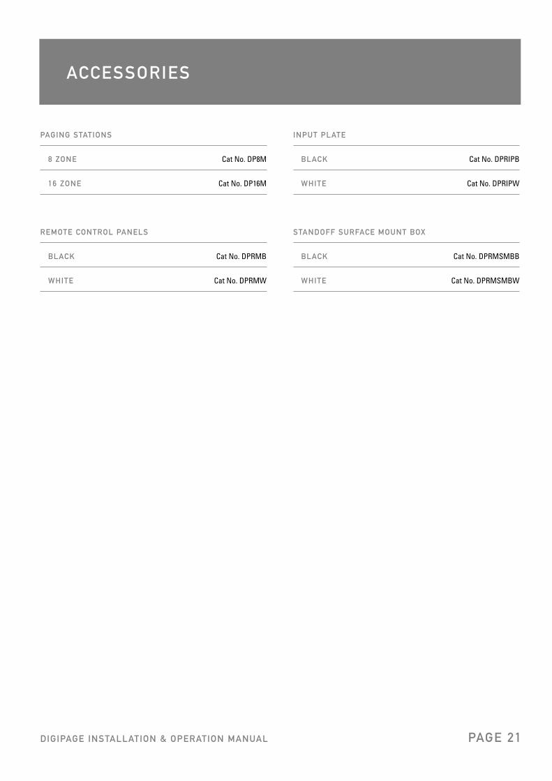
ACCESSORIES
DIGIPAGE INSTALLATION & OPERATION MANUAL PAGE 21
PAGING STATIONS
8 ZONE Cat No. DP8M
16 ZONE Cat No. DP16M
REMOTE CONTROL PANELS
BLACK Cat No. DPRMB
WHITE Cat No. DPRMW
INPUT PLATE
BLACK Cat No. DPRIPB
WHITE Cat No. DPRIPW
STANDOFF SURFACE MOUNT BOX
BLACK Cat No. DPRMSMBB
WHITE Cat No. DPRMSMBW

SPECIFICATIONS
PAGE 22 DIGIPAGE INSTALLATION & OPERATION MANUAL
DIMENSIONS (h x w x d) 133.0 x 483.0 x 180.5 mm
WEIGHT Net 6.0kg Shipping 7.0kgNet 13.2lb Shipping 15.4lb
POWER INPUT 20VAC30VA max
PROGRAM SOURCES ( tr im max)Unbalanced (RCA) Input Impedance:100kohm
Sensitivity: 150mV (-14dBu)Balanced (XLR) Input Impedance: 1k3ohm
Sensitivity: 1mV (-57dBu)Min Trim: -46dB
LOCAL SOURCEUnbalanced (RCA) Input Impedance: 100kohm
Sensitivity: 1.55V (+6dBu)Balanced (XLR)MIC Input Impedance: 1k3ohm
Sensitivity: 11mV (-37dBu)LINE Input Impedance: 45kohm
Sensitivity: 350mV (-7dBu)
SUM INPUT Input Sensitivity: 160mV (-13.5dBu)Threshold: -46dBu (at output, indpt of input)
FREQUENCY RESPONSE (0DB/-3DB) 15Hz - 17kHz
THD 0.005%
NOISE Page Mic: -84dBOther Inputs: -89dB
OUTPUT: 1.5Vrms 600ohmMax: 9Vrms
All measurements are reference to 1.5V (+6dBu)


SYDNEY(NSW & ACT SALES)
149 BeaconsfieldStreet SilverwaterNSW 2128 Private Bag 149Silverwater NSW 1811Phone: (02) 9647 1411Fax: (02) 9648 3698 Email:[email protected]
MELBOURNE(VIC & TAS SALES)
22/277 Middleborough RoadBox Hill VIC 3128 PO Box 151 BlackburnSouth VIC 3130 Phone: (03) 9890 7477Fax: (03) 9890 7977 Email:[email protected]
BRISBANE(QLD SALES)
42 Commercial RoadFortitude Valley QLD 4006 PO Box 871 FortitudeValley QLD 4006Phone: (07) 3852 1312Fax: (07) 3252 1237 Email:[email protected]
ADELAIDE(SA & NT SALES)
31 Walsh StreetThebarton SA 5031 PO Box 157 Hindmarsh SA 5007 Phone: (08) 8352 4444Fax: (08) 8352 4488 Email:[email protected]
PERTH(WA SALES)
299 Fitzgerald StreetWest Perth WA 6005 PO Box 404 North Perth WA 6906Phone: (08) 9228 4222Fax: (08) 9228 4233 Email:[email protected]
AUCKLAND(NZ SALES)
Unit B, 11 PiermarkDrive Albany 1331New ZealandPO Box 512 Albany 1331Phone: (09) 415 9426Fax: (09) 415 9864 Email:[email protected]
AUSTRALIA AND NEW ZEALANDwww.austral ianmonitor.com.au
INTERNATIONAL SALES
149 Beaconsfield Street Silverwater NSW 2128 AustraliaPrivate Bag 149 Silverwater NSW 1811Phone: 61 2 9647 1411 Fax: 61 2 9648 3698 Email: [email protected]
SENNHEISER ELECTRONIC CORPORATION
1 Enterprise DriveOld Lyme CT 06371 USAPhone: 1 860 434 9190Fax: 1 860 434 1759 Email: [email protected]
EUROPE/ASIA/MIDDLE EASTwww.austral ianmonitor.com.au
USA/SOUTH AMERICAwww.austral ianmonitor.com