Embed Size (px)
DESCRIPTION
Digital Logic
Citation preview

Chapter 1
BASIC DIGITAL CONCEPTS
Ch01L1-"Digital Principles and Design", Raj Kamal, Pearson Education, 2006 2
Lesson 1
Concepts of 1s and 0s

Ch01L1-"Digital Principles and Design", Raj Kamal, Pearson Education, 2006 3
Outline
•• StateState• Positive Logic Examples• Negative Logic Examples• Logic Circuit Examples

Ch01L1-"Digital Principles and Design", Raj Kamal, Pearson Education, 2006 4
Digital circuit
• An electronic circuit in which a state switches (changes) between two distinct circuit conditions when there are changes of input states or conditions
Ch01L1-"Digital Principles and Design", Raj Kamal, Pearson Education, 2006 5
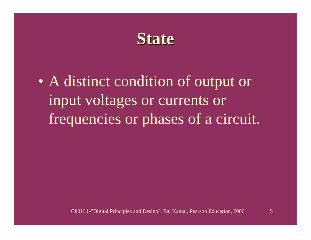
StateState
• A distinct condition of output or input voltages or currents or frequencies or phases of a circuit.
Ch01L1-"Digital Principles and Design", Raj Kamal, Pearson Education, 2006 6
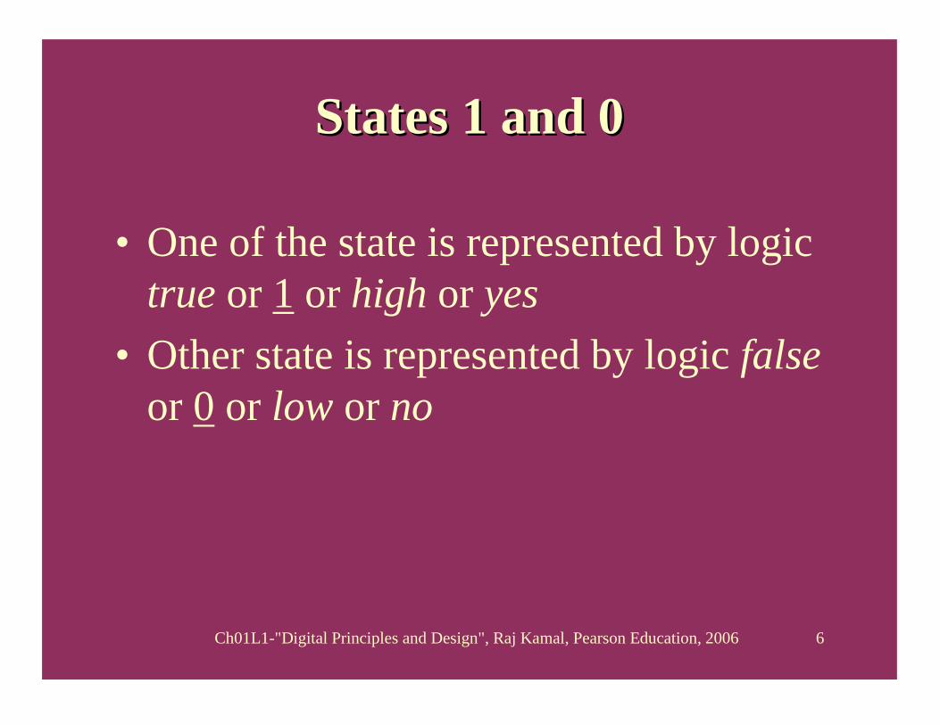
States 1 and 0States 1 and 0
• One of the state is represented by logic true or 1 or high or yes
• Other state is represented by logic falseor 0 or low or no

Ch01L1-"Digital Principles and Design", Raj Kamal, Pearson Education, 2006 7
Example State 1
5 V
Ground Potential
R
LED ON
Switch ON
Ccompleteconnection

Ch01L1-"Digital Principles and Design", Raj Kamal, Pearson Education, 2006 8
Example State 0
5 V
Ground Potential
R
LED OFF
Switch OFF
Complete connection
Ch01L1-"Digital Principles and Design", Raj Kamal, Pearson Education, 2006 9
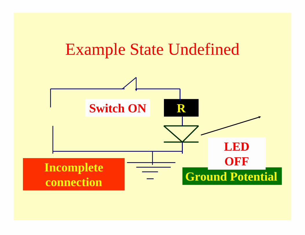
Example State Undefined
Incomplete connection Ground Potential
R
LED OFF
Switch ON

Ch01L1-"Digital Principles and Design", Raj Kamal, Pearson Education, 2006 10
Example State Undefined
5 V
Ground Potential
R
LED Not Connected
Switch ON
Ch01L1-"Digital Principles and Design", Raj Kamal, Pearson Education, 2006 11
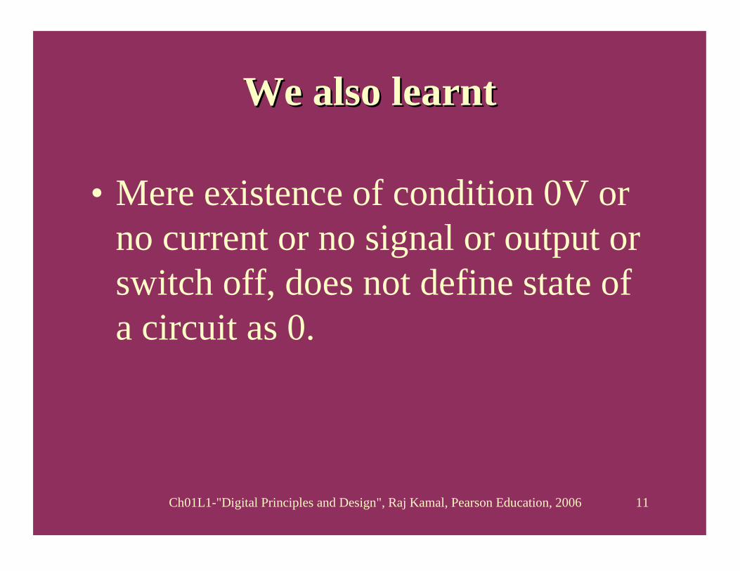
We also learnt We also learnt
• Mere existence of condition 0V or no current or no signal or output or switch off, does not define state of a circuit as 0.

Ch01L1-"Digital Principles and Design", Raj Kamal, Pearson Education, 2006 12
Outline
• State• Positive Logic Examples• Negative Logic Examples• Logic Circuit Examples

Ch01L1-"Digital Principles and Design", Raj Kamal, Pearson Education, 2006 13
Logic 0: Low or -V or mA or frequency
Logic 1: High or +ve V or mA or frequency
Positive Logic

Ch01L1-"Digital Principles and Design", Raj Kamal, Pearson Education, 2006 14
0
Positive Logic 1s and 0sPositive Logic 1s and 0s1
Maximum 5V Minimum 2.8 V
Maximum 0.8 VMinimum 0VMinimum 0V

Ch01L1-"Digital Principles and Design", Raj Kamal, Pearson Education, 2006 15
0
Positive Logic 1s and 0sPositive Logic 1s and 0s1
Maximum +5V Minimum +3.3V
Maximum + 1.7 VMinimum 0V

Ch01L1-"Digital Principles and Design", Raj Kamal, Pearson Education, 2006 16
0
Positive Logic 1s and 0sPositive Logic 1s and 0s1
Maximum + 20 mA Minimum + 16 mA
Maximum + 4 mAMinimum 0 mA

Ch01L1-"Digital Principles and Design", Raj Kamal, Pearson Education, 2006 17
0
Positive Logic 1s and 0sPositive Logic 1s and 0s1
Maximum 1260 Hz frequency Minimum 1220 Hz frequency
Maximum 1060 Hz frequencyMinimum 1020 Hz frequency

Ch01L1-"Digital Principles and Design", Raj Kamal, Pearson Education, 2006 18
Outline
• State• Positive Logic Examples•• Negative Logic Negative Logic ExamplesExamples• Logic Circuit Examples

Ch01L1-"Digital Principles and Design", Raj Kamal, Pearson Education, 2006 19
Logic 1: Low or -ve V or mA or frequency
Logic 0: High V or mA or frequency
Negative Logic
Ch01L1-"Digital Principles and Design", Raj Kamal, Pearson Education, 2006 20
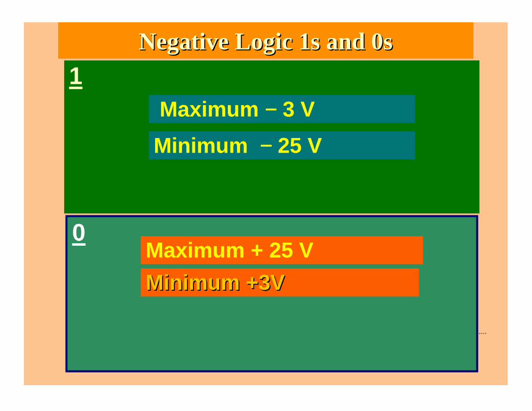
0
Negative Logic 1s and 0sNegative Logic 1s and 0s1
Maximum −−−− 3 V Minimum −−−− 25 V
Maximum + 25 VMinimum Minimum +3V +3V
Ch01L1-"Digital Principles and Design", Raj Kamal, Pearson Education, 2006 21
Outline
• State• Positive Logic Examples• Negative Logic Examples•• Logic Circuit ExamplesLogic Circuit Examples

Ch01L1-"Digital Principles and Design", Raj Kamal, Pearson Education, 2006 22
0
A TTL circuit Logic 1s and 0sA TTL circuit Logic 1s and 0s1
Maximum 5V Minimum 2.8 V
Maximum 0.8 VMinimum 0VMinimum 0V
Output stage Transistor Off
Output stage Transistor ON
Output stage Transistor current 40 µµµµA
Output stage Transistor current 4 mA

Ch01L1-"Digital Principles and Design", Raj Kamal, Pearson Education, 2006 23
0
A CMOS circuit Logic 1s and 0sA CMOS circuit Logic 1s and 0s1
Maximum 5V Minimum 3.3 V
Maximum 1.6 VMinimum 0VMinimum 0V
Output stage MOSFET Off
Output stage MOSFET ON
Output stage MOSFET drain current 0 µµµµA at dc
Output stage MOSFET drain current 0 µµµµA at dc

Ch01L1-"Digital Principles and Design", Raj Kamal, Pearson Education, 2006 24
0
An RS232C circuit Logic 1s and 0sAn RS232C circuit Logic 1s and 0s1
Maximum -3V
Minimum -25 V
Maximum +25VMinimum 3VMinimum 3V
Output stage MOSFET ON
Output stage MOSFET OFF
Output stage MOSFET drain current 0 µµµµA at dc
Output stage MOSFET drain current 0 µµµµA at dc
Ch01L1-"Digital Principles and Design", Raj Kamal, Pearson Education, 2006 25
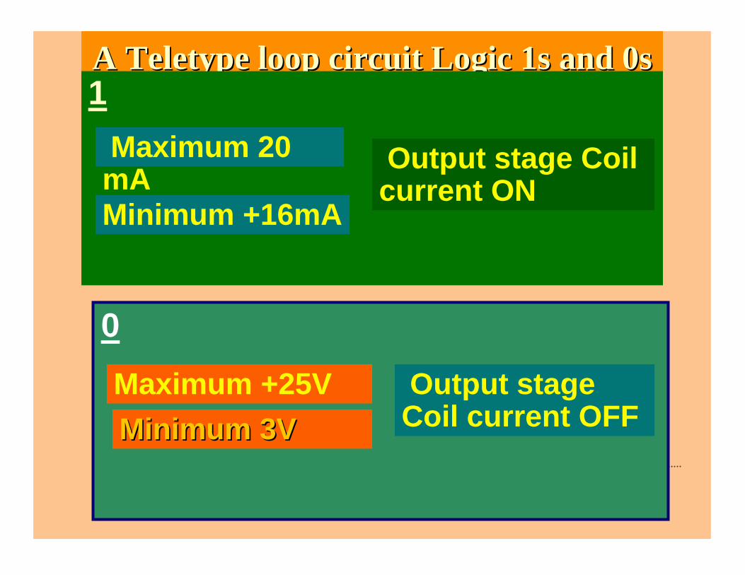
0
A Teletype loop circuit Logic 1s and 0sA Teletype loop circuit Logic 1s and 0s1
Maximum 20 mA Minimum +16mA
Maximum +25VMinimum 3VMinimum 3V
Output stage Coil current ON
Output stage Coil current OFF

Ch01L1-"Digital Principles and Design", Raj Kamal, Pearson Education, 2006 26
0
A Modem circuit Logic 1s and 0sA Modem circuit Logic 1s and 0s1
Maximum 1260 Hz
Minimum 1220 Hz
Maximum 1060 HzMinimum 1020Minimum 1020

Ch01L1-"Digital Principles and Design", Raj Kamal, Pearson Education, 2006 27
Example State 1
5 V
Ground Potential
Modem Oscillator
Frequency 1240 Hz
Switch ON

Ch01L1-"Digital Principles and Design", Raj Kamal, Pearson Education, 2006 28
Example State 0
5 V
Ground Potential
Modem Oscillator
Frequency 1040 Hz
Switch ON

Ch01L1-"Digital Principles and Design", Raj Kamal, Pearson Education, 2006 29
Example State Undefined
5 V
Ground Potential
Modem Oscillator
Output < = 1000Hz
Switch ON

Ch01L1-"Digital Principles and Design", Raj Kamal, Pearson Education, 2006 30
0
A Modulation circuit Logic 1s and 0sA Modulation circuit Logic 1s and 0s1
Phase angle + 90°°°°6666 45°°°°
Phase angle −−−−90°°°°6666 45°°°°
Ch01L1-"Digital Principles and Design", Raj Kamal, Pearson Education, 2006 31
Summary
Ch01L1-"Digital Principles and Design", Raj Kamal, Pearson Education, 2006 32
• 1 represents a state of a circuit• 0 represents another state of circuit
Ch01L1-"Digital Principles and Design", Raj Kamal, Pearson Education, 2006 33
• Different family of circuits have different discrete circuit conditions for 1 or 0 states. A condition may be defined by a range voltage, current, frequency or phase angle

Ch01L1-"Digital Principles and Design", Raj Kamal, Pearson Education, 2006 34
We also learnt We also learnt
• Mere existence of condition 0V or no current or no signal or output or switch OFF, does not define state of a circuit as 0 or 1.

Ch01L1-"Digital Principles and Design", Raj Kamal, Pearson Education, 2006 35
We also learnt We also learnt
• Mere existence of connection to high voltage or high current or a signal or output or switch ON, does not define state of a circuit as 0.

Ch01L1-"Digital Principles and Design", Raj Kamal, Pearson Education, 2006 36
End of Lesson 1 on
Concepts of 1s and 0s

Ch01L1-"Digital Principles and Design", Raj Kamal, Pearson Education, 2006 37
THANK YOU


