Embed Size (px)
Citation preview
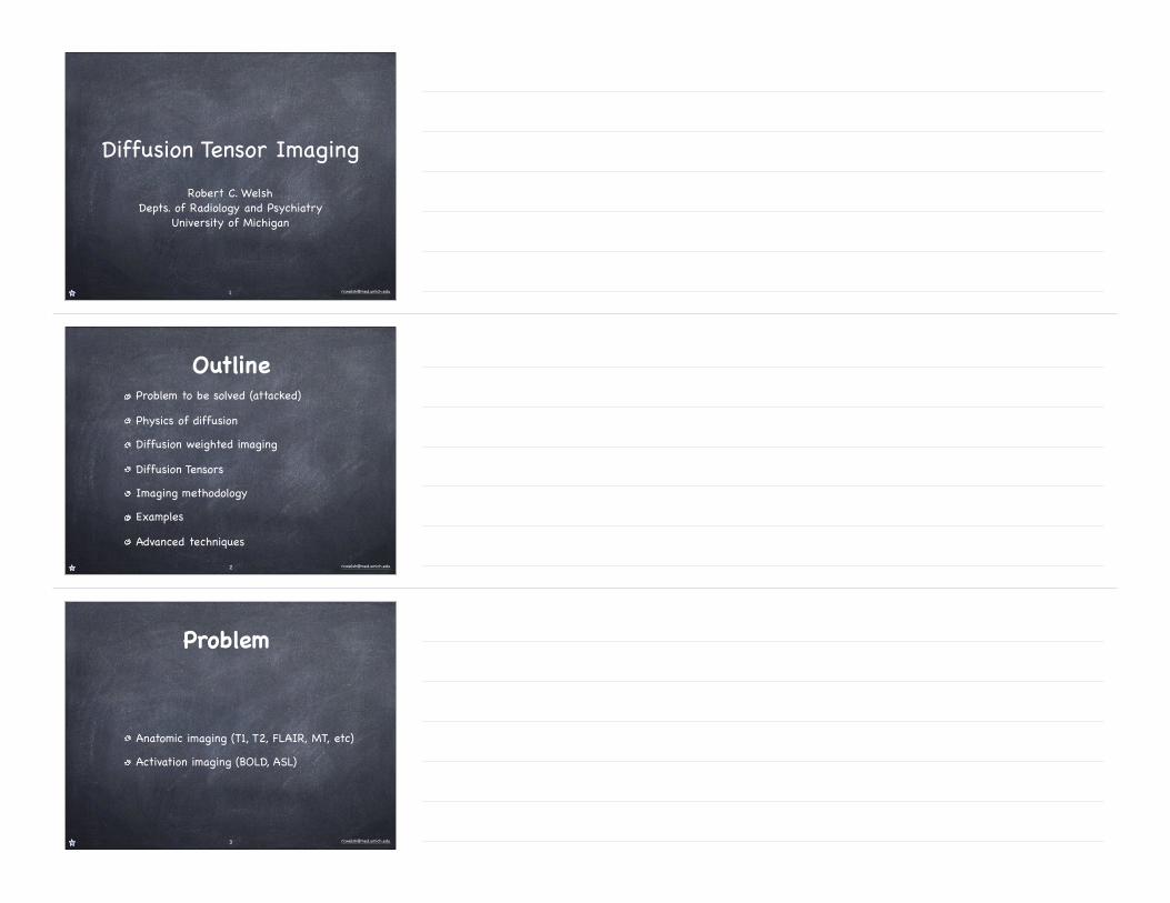
Diffusion Tensor ImagingRobert C. Welsh
Depts. of Radiology and PsychiatryUniversity of Michigan
1
OutlineProblem to be solved (attacked)Physics of diffusionDiffusion weighted imagingDiffusion TensorsImaging methodologyExamplesAdvanced techniques
2
Problem
Anatomic imaging (T1, T2, FLAIR, MT, etc)Activation imaging (BOLD, ASL)
3

Anatomic ImagingT2 T1 FLAIR
4
Activation Studies
5
ProblemDynamics of white-matterActivation gives temporally correlated regions of grey matter
Unfortunately we can’t put tracers in humans.
6
graphy to other anisotropic or fibrous soft tissues suchas peripheral nerves, the myocardium, ligaments, ten-dons, and skeletal muscles [12].
The objective of this paper is to provide an introduc-tion to the basics and current advances of MRtractography and to address potential limitations andcommon pitfalls. Despite the fact that tractography is arelatively novel technique, there have been a fewpublications that have focused on potential clinicalapplications and these will also be addressed in thisreview.
2. Diffusion tensor imaging
In media with anisotropic Gaussian diffusion proper-ties, it has been shown that the displacement front of adiffusing substance can be modeled as an ellipsoid [13].Hence, each diffusion-weighted measurement reveals,for every voxel during a defined observation interval,the displacement from the origin to a point on theellipsoid surface along the direction of the diffusion-sensitizing gradient [4]. Acquiring MR data by usingvarious gradient orientations, a set of points has beensampled on the ellipsoid surface to define its size, shape,and orientation to within the limits of sampling error.The mathematical construct used to characterize aniso-tropic Gaussian diffusion is a second-order diffusiontensor (D). DT-MRI measures the diffusion propertiesof water along specific directions, which allows one toidentify the unknown elements of the tensor for each
pixel [3,4]. Since the tensor is symmetric, only six uniqueelements are required to fully characterize the tensor.
A second-rank tensor (3!/3 matrix) can be diagona-lized, such that only three non-zero elements (l1, l2, andl3) remain along the diagonal. These elements areknown as the eigenvalues and are shown in the followingmatrix factorization:
D"Dxx Dxy Dxz
Dxy Dyy Dyz
Dxz Dyz Dzz
0
@
1
A
" [v1 v2 v3]T
l1 0 00 l2 00 0 l3
0
@
1
A[v1 v2 v3]: (1)
The eigenvalues define the diffusion coefficients alongthe major and minor axes of the diffusion ellipsoid.Here, each eigenvalue is associated with an eigenvector(v1, v2, and v3) [14], where conventionally the largesteigenvalue l1 corresponds to v1. The orientation of thesethree orthogonal eigenvectors can be expressed in termsof a 3D rotation with respect to the laboratory frame ofreference (Fig. 2).
Although diffusion anisotropy exists in unmyelinatednerves (as shown in studies of garfish olfactory nerves[15] and neonates [16]), it is widely assumed that themyelin sheath surrounding nerve fibers acts as the mainbarrier to water diffusion. Therefore, in DT-MRItractography it is assumed that the eigenvector asso-ciated with the largest eigenvalue is aligned with thedirection of the fiber bundle. While this might lead tothe assumption that the contrast of diffusion-weightedimages is the result of tissue microstructure, it is
Fig. 1. Brain dissection showing the structure of white matter (Williams et al.) using the preservation method of Klinger from the Iowa Virtualhospital: http://www.vh.org/Providers/Textbooks/BrainAnatomy/TOC.html. Internal capsule and corona radiate (left): from the relatively narrow,but thick, basis pedunculi, the fibers are fanning out to extensive areas of cerebral cortex. Corpus callosum, its radiation, and indusium griseumshown from above (right): the hemispheres are partly removed to demonstrate these structures. The transversely oriented commissural fibers areclearly visible. The commissural fibers traversing the splenium and genu of the corpus callosum show typical arches. The upper surface of the medianportion of the corpus callosum is covered by a thin veil of the indusium griseum (gray matter).
R. Bammer et al. / European Journal of Radiology 45 (2003) 223#/234224
Physics of Diffusion (Brownian Motion)Particles (dust, molecules, atom) in liquid/gaseous state randomly move about.
Described by Brown and Einstein Brown R. A brief account of microscopical observations and on the general existence of active molecules in organic and inorganic bodies. In: The Philosophical Magazine, vol. IV. London: Richard Taylor; 1828. p 161–173.
Einstein A. About the movement of suspended particles in liquids at rest as required by the molecular kinetic theory of heat. [Uber die von der molekularkinetischen Theorie der Warme geforderte Bewegung von in ruhenden Flussigkeiten suspendierten Teilchen]. Ann Phys 1905;322:549 –560. (Ger)
8
What determines the properties of this random motion?
MassSize (a.k.a. radius)Energy (temperature � velocity)
9
Stokes-Einstein Equation gives diffusion coefficient D
D =kT
6πηr(water versus honey)
10
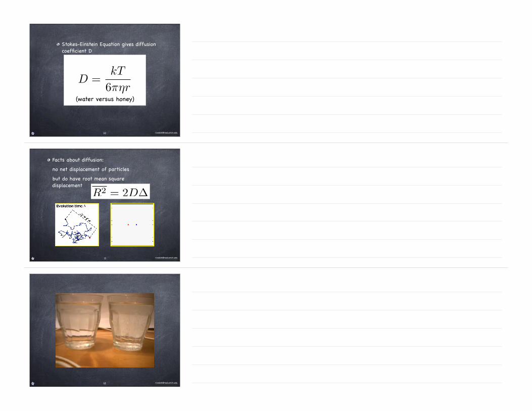
Facts about diffusion:no net displacement of particles but do have root mean square displacement
R2 = 2D∆
11
Diffusion Weighted Imaging (DWI)
We need to be able to detect random motion and to image this random motion.
However, this random motion is on a microscopic scale compared to imaging resolution.
13
Concept of Phase
14
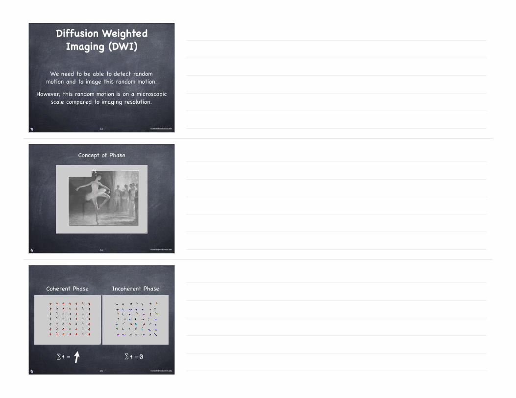
Coherent Phase Incoherent Phase
∑ = ∑ = 0
15
ω = γB0
B(x) = B0 + Gx
ω(x) = γ(B0 + Gx)
φ(x) = ω(x)δ, δ = time
16
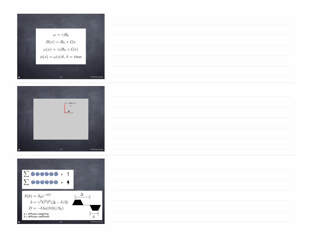
S(b) = S0e−bD
b = diffusion weightingD = diffusion coefficient
D = −b ln(S(b)/S0)
!
!=
=
b = γ2G2δ2(∆ − δ/3)
δ
∆
18
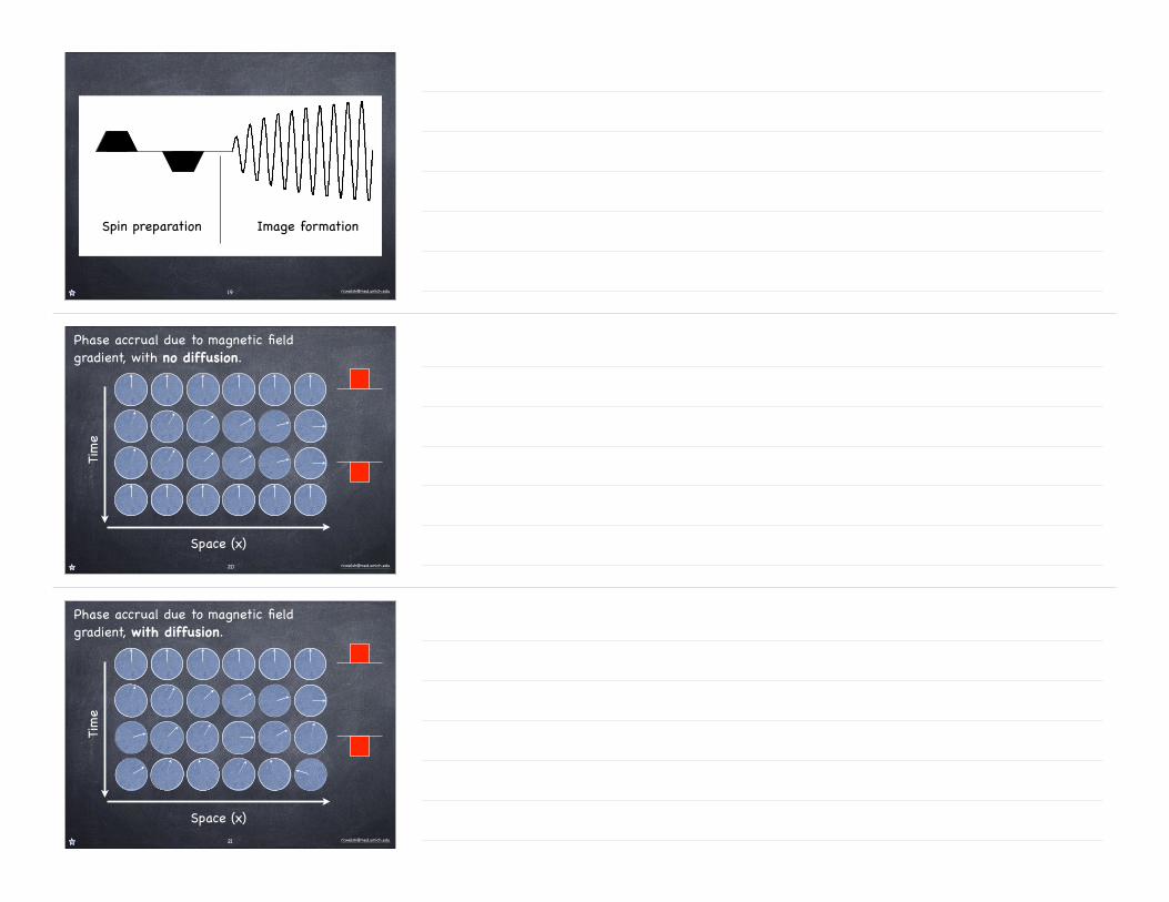
Spin preparation Image formation
19
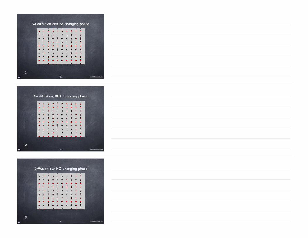
Phase accrual due to magnetic field gradient, with no diffusion.
Time
Space (x)20
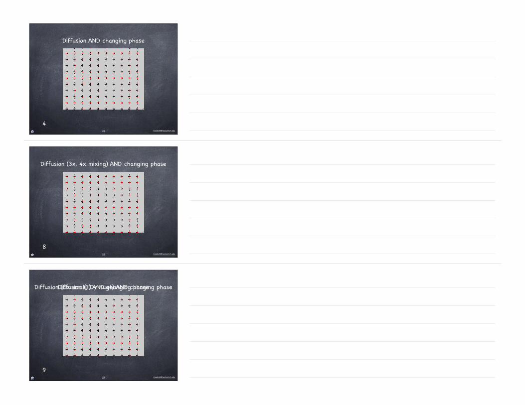
Phase accrual due to magnetic field gradient, with diffusion.
Time
Space (x)21
No diffusion and no changing phase
122
No diffusion, BUT changing phase
223
Diffusion but NO changing phase
324
Diffusion AND changing phase
425
Diffusion (3x, 4x mixing) AND changing phase
826
Diffusion (?) AND changing phase
9
Diffusion (Dx small, Dy huge) AND changing phase
27
Diffusion (??) AND changing phase
10
Diffusion (Dx huge, Dy small) AND changing phase
28
Dx
Mix
ing
Final phaseof spins
δ
∆
29
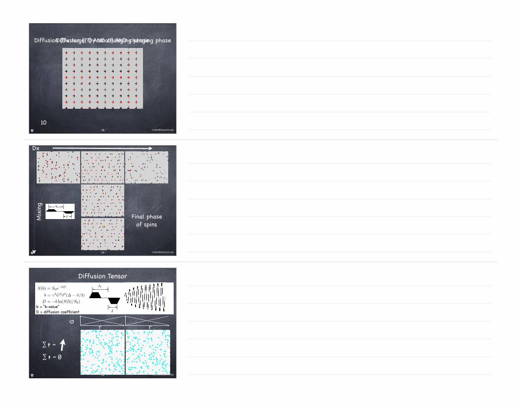
Diffusion TensorS(b) = S0e
−bD
b = “b-value”D = diffusion coefficient
D = −b ln(S(b)/S0)
b = γ2G2δ2(∆ − δ/3)
δ
∆
∑ =
∑ = 0
r
G
r
30

Artifacts
Unlike high resolution imaging, very susceptible to shot-to-shot (excitation) errorVERY susceptible to bulk motion, cardiac pulsatilitySPIRAL or EPI, but then low-resolutionParallel imaging (SENSE), or multi-shot with phase correction
31
S0 S(b) ADC
Simple Diffusion Weighted Imaging
b ~ 800 s/mm2
32
graphy to other anisotropic or fibrous soft tissues suchas peripheral nerves, the myocardium, ligaments, ten-dons, and skeletal muscles [12].
The objective of this paper is to provide an introduc-tion to the basics and current advances of MRtractography and to address potential limitations andcommon pitfalls. Despite the fact that tractography is arelatively novel technique, there have been a fewpublications that have focused on potential clinicalapplications and these will also be addressed in thisreview.
2. Diffusion tensor imaging
In media with anisotropic Gaussian diffusion proper-ties, it has been shown that the displacement front of adiffusing substance can be modeled as an ellipsoid [13].Hence, each diffusion-weighted measurement reveals,for every voxel during a defined observation interval,the displacement from the origin to a point on theellipsoid surface along the direction of the diffusion-sensitizing gradient [4]. Acquiring MR data by usingvarious gradient orientations, a set of points has beensampled on the ellipsoid surface to define its size, shape,and orientation to within the limits of sampling error.The mathematical construct used to characterize aniso-tropic Gaussian diffusion is a second-order diffusiontensor (D). DT-MRI measures the diffusion propertiesof water along specific directions, which allows one toidentify the unknown elements of the tensor for each
pixel [3,4]. Since the tensor is symmetric, only six uniqueelements are required to fully characterize the tensor.
A second-rank tensor (3!/3 matrix) can be diagona-lized, such that only three non-zero elements (l1, l2, andl3) remain along the diagonal. These elements areknown as the eigenvalues and are shown in the followingmatrix factorization:
D"Dxx Dxy Dxz
Dxy Dyy Dyz
Dxz Dyz Dzz
0
@
1
A
" [v1 v2 v3]T
l1 0 00 l2 00 0 l3
0
@
1
A[v1 v2 v3]: (1)
The eigenvalues define the diffusion coefficients alongthe major and minor axes of the diffusion ellipsoid.Here, each eigenvalue is associated with an eigenvector(v1, v2, and v3) [14], where conventionally the largesteigenvalue l1 corresponds to v1. The orientation of thesethree orthogonal eigenvectors can be expressed in termsof a 3D rotation with respect to the laboratory frame ofreference (Fig. 2).
Although diffusion anisotropy exists in unmyelinatednerves (as shown in studies of garfish olfactory nerves[15] and neonates [16]), it is widely assumed that themyelin sheath surrounding nerve fibers acts as the mainbarrier to water diffusion. Therefore, in DT-MRItractography it is assumed that the eigenvector asso-ciated with the largest eigenvalue is aligned with thedirection of the fiber bundle. While this might lead tothe assumption that the contrast of diffusion-weightedimages is the result of tissue microstructure, it is
Fig. 1. Brain dissection showing the structure of white matter (Williams et al.) using the preservation method of Klinger from the Iowa Virtualhospital: http://www.vh.org/Providers/Textbooks/BrainAnatomy/TOC.html. Internal capsule and corona radiate (left): from the relatively narrow,but thick, basis pedunculi, the fibers are fanning out to extensive areas of cerebral cortex. Corpus callosum, its radiation, and indusium griseumshown from above (right): the hemispheres are partly removed to demonstrate these structures. The transversely oriented commissural fibers areclearly visible. The commissural fibers traversing the splenium and genu of the corpus callosum show typical arches. The upper surface of the medianportion of the corpus callosum is covered by a thin veil of the indusium griseum (gray matter).
R. Bammer et al. / European Journal of Radiology 45 (2003) 223#/234224
54 PART I Cellular Neurochemistry and Neural Membranes
layers of the original cell membrane; the membranes are not actually fused, as they can be resolved as a double line at high resolution (Figs 4-6, 4-7). The dark, or major period, line is the fused, inner protein layers of the cell membrane. The repeat distances observed by electron microscopy are less than those calculated from the low-angle X-ray diffraction data, a consequence of the consid-erable shrinkage that takes place after fixation and dehydration. However, the difference in periodicity between the PNS myelin and CNS myelin is maintained; peripheral myelin has an average repeat distance of 119 Å and the central myelin of 107 Å.
Nodes of Ranvier. Two adjacent segments of myelin on one axon are separated by a node of Ranvier. In this region the axon is not covered by myelin. At the paranodal region and the Schmidt–Lantermann clefts (see below), the cyto-plasmic surfaces of myelin are not compacted and Schwann or glial cell cytoplasm is included within the sheath. To visualize these structures, one may refer to Figures 4-8 and 4-9, which show that if myelin were unrolled from the axon it would be a flat, spade-shaped sheet surrounded by a tube of cytoplasm. Thus, as shown in electron micrographs of longitudinal sections of axon paranodal regions, the major dense line formed by appo-sition of the cytoplasmic faces opens up at the edges of the sheet, enclosing cytoplasm within a loop (Figs 4-3, 4-9).
These loop-shaped terminations of the sheath at the node are called lateral loops. The loops form membrane com-plexes with the axolemma called transverse bands, whereas myelin in the internodal region is separated from the axon by an extracellular gap of periaxonal space. The transverse bands are helical structures that seal the myelin to the axo-lemma but provide, by spaces between them, a tortuous path from the extracellular space to the periaxonal space.
FIGURE 4-5 Higher magnification of Figure 4-4 to show the Schwann cell cytoplasm covered by basal lamina (arrows).
FIGURE 4-6 Magnification of the myelin sheath of Figure 4-4. Note that the intraperiod line (arrows) at this high resolution is a double structure. (Courtesy of Dr Cedric Raine.)
FIGURE 4-7 A typical CNS myelinated fiber from the spinal cord of an adult dog. Contrast this figure with the PNS fiber in Figure 4-4. The course of the flattened oligodendrocytic process, beginning at the outer tongue (arrow), can be traced. Note that the fiber lacks investing cell cytoplasm and a basal lamina–as is the case in the PNS. The major dense line and the paler, double intraperiod line of the myelin sheath can be discerned. The axon contains microtubules and neurofilaments.
Inner cytoplasmic tongue
Outer cytoplasmic
tongue
Majordenseline
LateralloopsCompact
myelin
Axon
FIGURE 4-8 A diagram showing the appearance of CNS myelin if it were unrolled from the axon. One can visualize this structure arising from Figure 4-3 if the glial cell process were pulled straight up and the myelin layers separated at the intermediate period line. The whole myelin internode forms a spade-shaped sheet surrounded by a continu-ous tube of oligodendroglial cell cytoplasm. This diagram shows that the lateral loops and inner and outer cytoplasmic tongues are parts of the same cytoplasmic tube. The drawing on the right shows the appear-ance of this sheet if it were sectioned along the vertical line, indicating that the compact myelin region is formed of two unit membranes fused at the cytoplasmic surfaces. The drawing is not necessarily to scale. (Adapted from Hirano, A. and Dembitzer, H. M. A structural analysis of the myelin sheath in the central nervous system. J. Cell Biol. 34: 555–567, 1967.)
Siegel_01.indd 4 8/24/05 8:28:29 PM
elin, but it is focally unmyelinated at loci, termed nodes ofRanvier; the myelinated region between adjacent nodes ofRanvier is referred to as an internode. Each oligodendrocytecan form multiple myelin internodes with multiple axons,and the number of internodes is regulated by axons. Whenmyelination is initiated, all axons are the same size; how-ever, oligodendrocytes appear to have the ability to predictthe future diameter of axons and create myelin internodesthat are thinner and shorter on those axons that will remainsmaller, while myelinating longer and thicker internodes onthose axons that will attain a large diameter.3 Each myelininternode can be divided into two ultrastructurally and func-tionally distinct domains: 1) paranodal loops and 2) com-pact myelin. Paranodal loops facilitate ion exchange at thenode of Ranvier by providing a high concentration of so-dium channels and compact myelin inhibits ion exchangeduring nerve conduction.3
The myelin bilayer is made up of approximately 80%lipid and 20% protein and it is composed of repeatingunits of the major dense line formed by fusion of thecytoplasmic aspects of the oligodendrocyte process, al-ternating with the extracellular space between adjacentprocesses, the intraperiod line. The intraperiod line isthus an extension of the extracellular space and as such
should have a relatively high-water content (WC). Theintracellular and extracellular space in between the bi-layers is filled with water, which makes up approxi-mately 40% of the weight of myelin1 (FIG. 1). Myelinhas a periodicity of about 150 angstrom to 160 ang-strom.5
A variety of proteins contribute to myelin’s ultrastruc-ture including3:
1. Myelin Basic Protein (MBP) is a basic proteinmaking up approximately 30% of the myelin pro-teins and is localized at the cytoplasmic surface ofcompact myelin.
2. Proteolipid Protein (PLP) is a hydrophobic pro-tein with four membrane-spanning domains, mak-ing up about 50% of the myelin proteins. The PLPmaintains the 30 angstrom extracellular spacing ofcompact myelin by electrostatic interactions withmyelin lipids.
3. Cyclic Nucleotide Phosphodiesterase (CNP)makes up about 4% of the myelin proteins and isconcentrated on the cytoplasmic side of the myelinlamellae.
FIG. 1. The CNS myelin sheath surrounding an axon with inset depicting close up of bilayer, including myelin basic protein (MBP),proteolipid protein (PLP), cyclic nucleotide phosphodiesterase (CNP), and myelin-associated glycoprotein (MAG).
MRI OF MYELIN 461
Neurotherapeutics, Vol. 4, No. 3, 2007
...but what if there is something that impedes free diffusion?...or even impedes in one direction but not another
33
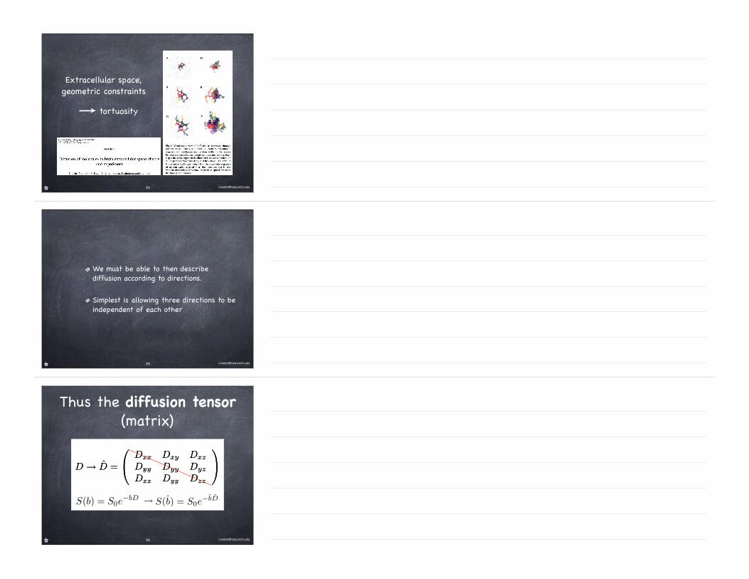
Extracellular space, geometric constraints
tortuosity
34
We must be able to then describe diffusion according to directions.
Simplest is allowing three directions to be independent of each other
35
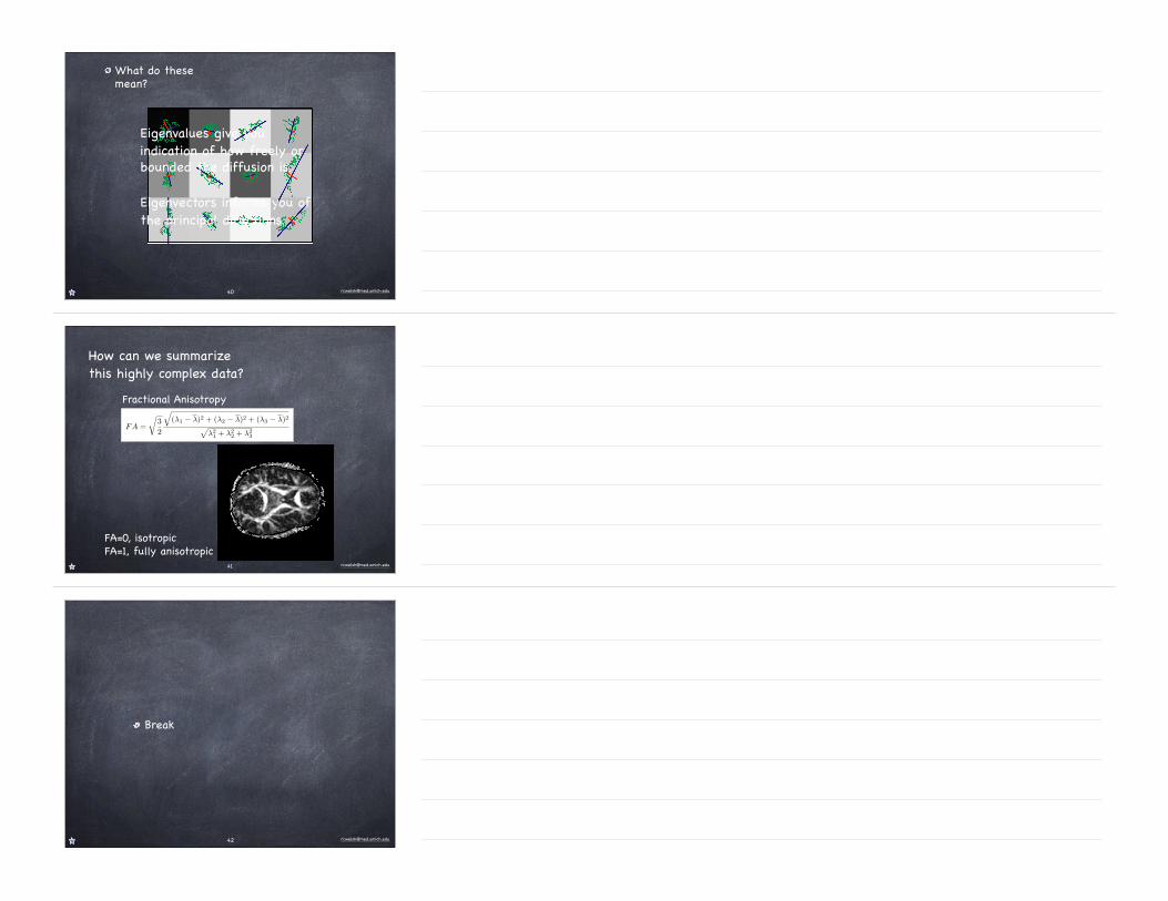
Thus the diffusion tensor (matrix)
D → D̂ =
⎛
⎝
Dxx Dxy Dxz
Dyx Dyy Dyz
Dzx Dzy Dzz
⎞
⎠
S(b̂) = S0e−b̂D̂S(b) = S0e
−bD→
D → D̂ =
⎛
⎝
Dxx Dxy Dxz
Dxy Dyy Dyz
Dxz Dyz Dzz
⎞
⎠
36
Must now take diffusion weighted images with magnetic gradients along different directions.
7 Unknowns...must make at least 7 measurements.
33
Operationally like a time series, but each volume has “diffusion weighting”. Very, very sensitive to movement.
Imaging
37
Diffusion Tensor
38
λ̂ =
⎛
⎝
λ1 0 0
0 λ2 0
0 0 λ3
⎞
⎠
ϵ1, ϵ2, ϵ3
λ1, λ2, λ3
Application of linear algebra
Eigenvalues
Eigenvectors
D̂ =
⎛
⎝
Dxx Dxy Dxz
Dxy Dyy Dyz
Dxz Dyz Dzz
⎞
⎠
39
What do these mean?
Eigenvalues give you indication of how freely or bounded the diffusion is.
Eigenvectors informs you of the principal directions.
40
FA =
!
3
2
"
(λ1 − λ)2 + (λ2 − λ)2 + (λ3 − λ)2#
λ21
+ λ22
+ λ23
Fractional Anisotropy
How can we summarize this highly complex data?
FA=0, isotropicFA=1, fully anisotropic
41
Break
42