Embed Size (px)
Citation preview
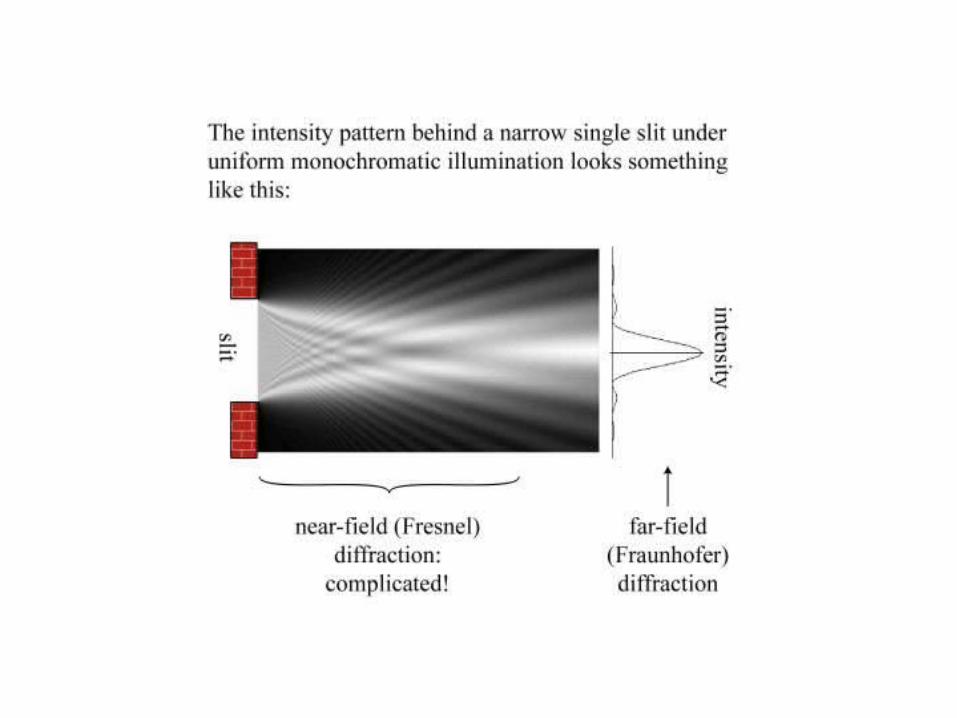
Diffraction
See Chapter 10 of Hecht
Diffraction
• Send light through apertures, slits or gratings
• Predict intensity distribution of light
• Further examples of interference.
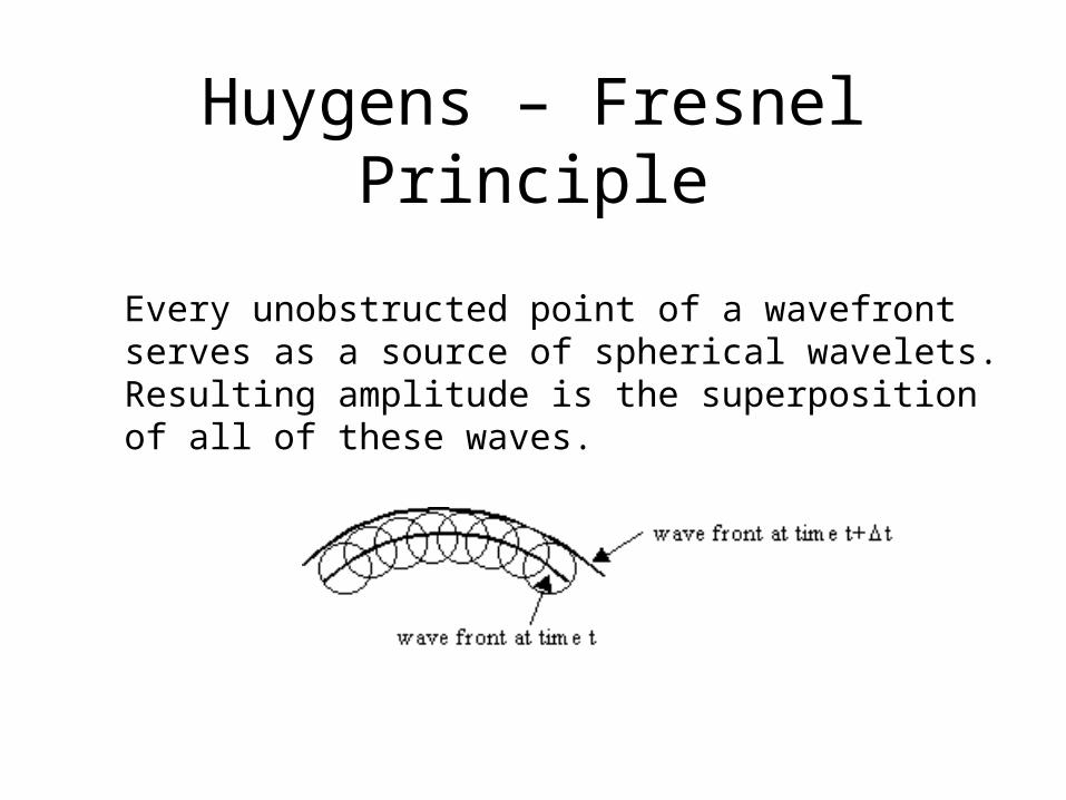
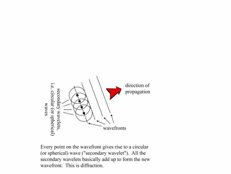
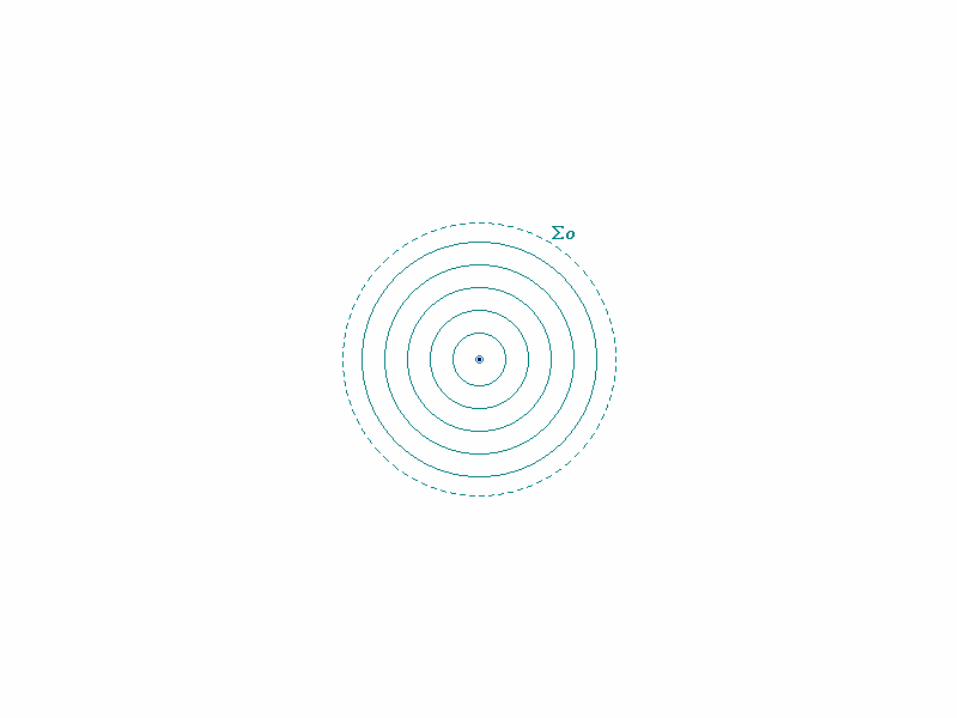
Huygens – Fresnel Principle
Every unobstructed point of a wavefront serves as a source of spherical wavelets. Resulting amplitude is the superposition of all of these waves.
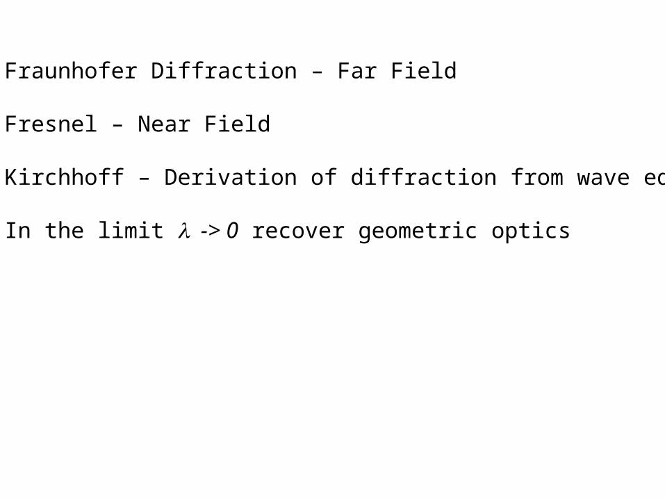
Fraunhofer Diffraction – Far Field
Fresnel – Near Field
Kirchhoff – Derivation of diffraction from wave equation
In the limit -> 0 recover geometric optics

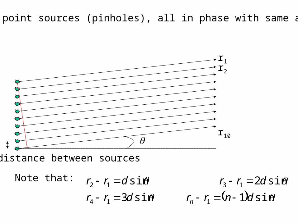
Line of point sources (pinholes), all in phase with same amplitude
d=distance between sources
r2
r1
r10
Note that:
sin1sin3
sin2sin
114
1312
dnrrdrr
drrdrr
n
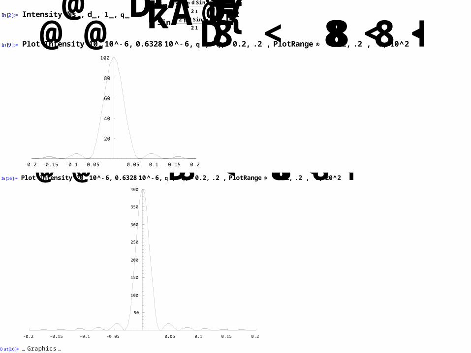
In[2]:= Intensity@Ns_, d_, l _,q_D:=ikSinANs2 pdSin@qD2 lE
SinA2 pdSin@qD2 lEy{^2
In[9]:= Plot@Intensity@10, 10^- 6, 0.632810^- 6,qD,8q, - 0.2, .2<, PlotRange®88- .2, .2<,80, 10^2<<D
-0.2 -0.15 -0.1 -0.05 0.05 0.1 0.15 0.2
20
40
60
80
100
Out[9]= … Graphics …In[16]:= Plot@Intensity@20, 10^- 6, 0.632810^- 6,qD,8q, - 0.2, .2<, PlotRange®88- .2, .2<,80, 20^2<<D
-0.2 -0.15 -0.1 -0.05 0.05 0.1 0.15 0.2
50
100
150
200
250
300
350
400
Out[16]= … Graphics …
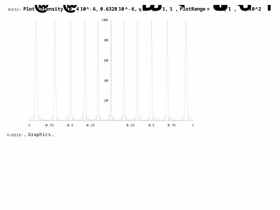
In[13]:= Plot@Intensity@10, 410^- 6, 0.632810^- 6,qD,8q, - 1, 1<, PlotRange®88- 1, 1<,80, 10^2<<D
-1 -0.75 -0.5 -0.25 0.25 0.5 0.75 1
20
40
60
80
100
Out[13]= … Graphics …
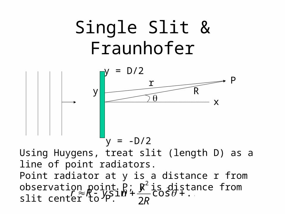
Single Slit & Fraunhofer
x
y = D/2
y = -D/2
rR
P
Using Huygens, treat slit (length D) as a line of point radiators.Point radiator at y is a distance r from observation point P; R is distance from slit center to P.
y
...cos2
sin 22
R
yyRr
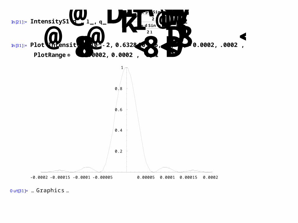
In[21]:= IntensityS1@d_, l _, q_D:=ikSinA2 pdSin@qD2 lEI2 pdSin@qD
2 lMy{^2
In[31]:= Plot@IntensityS1@10^- 2, 0.632810^- 6, qD,8q, - 0.0002, .0002<,PlotRange®88-0.0002, 0.0002<,80, 1<<D
-0.0002 -0.00015 -0.0001 -0.00005 0.00005 0.0001 0.00015 0.0002
0.2
0.4
0.6
0.8
1
Out[31]= … Graphics …
x
P
z
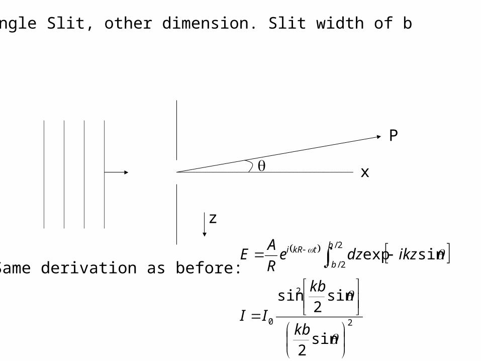
Single Slit, other dimension. Slit width of b
Same derivation as before:
2
2
0
2/
2/
sin2
sin2
sin
sinexp
kb
kb
II
ikzdzeR
AE
b
b
tkRi
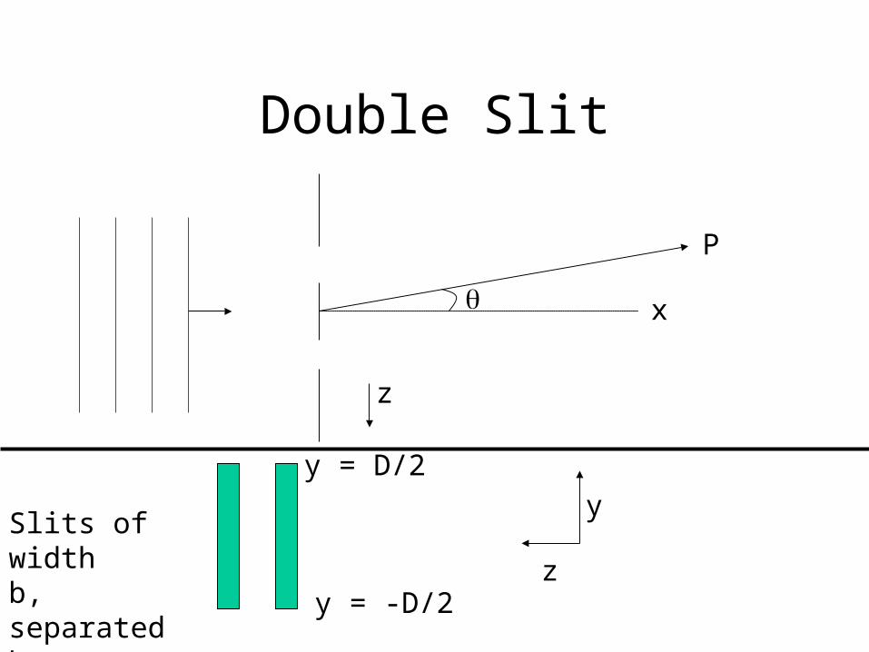
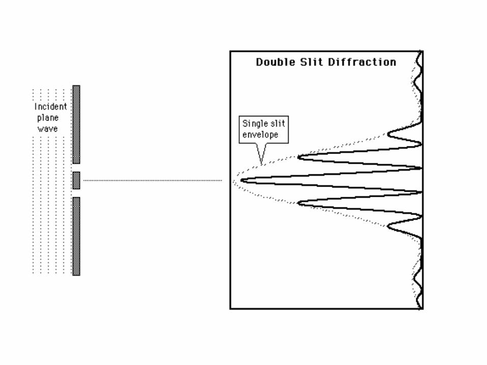
Double Slit
x
P
z
y
z
y = D/2
y = -D/2
Slits of widthb, separated by distance a.
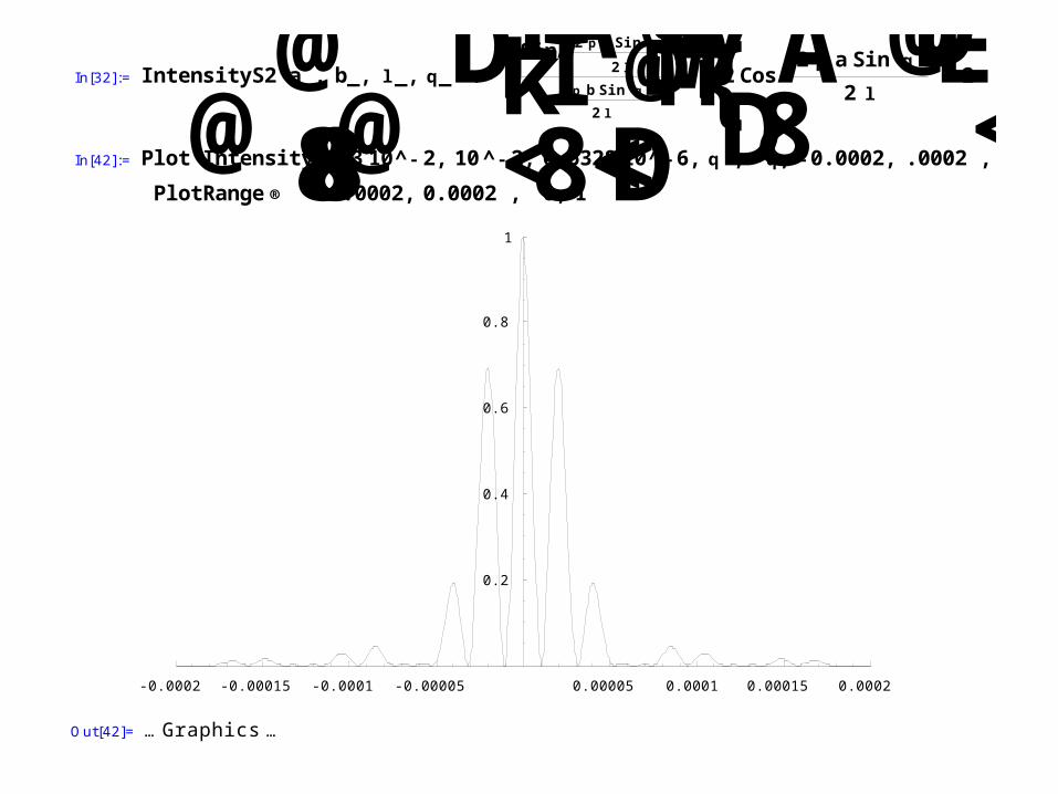
In[32]:= IntensityS2@a_, b_, l _, q_D:=ikSinA2 pbSin@qD2 lEI2 pbSin@qD
2 lMy{^2CosA2 paSin@qD2 l
E2In[42]:= Plot@IntensityS2@310^- 2, 10^- 2, 0.632810^-6, qD,8q, -0.0002, .0002<,
PlotRange®88-0.0002, 0.0002<,80, 1<<D
-0.0002 -0.00015 -0.0001 -0.00005 0.00005 0.0001 0.00015 0.0002
0.2
0.4
0.6
0.8
1
Out[42]= … Graphics …
Line of point sources (pinholes), all in phase with same amplitude
d=distance between sources
r2
r1
r10
Note that:
sin1sin3
sin2sin
114
1312
dnrrdrr
drrdrr
n
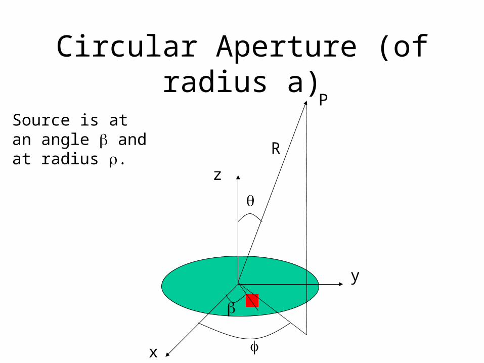
Circular Aperture (of radius a)
z
y
x
P
R
Source is at an angle and at radius .
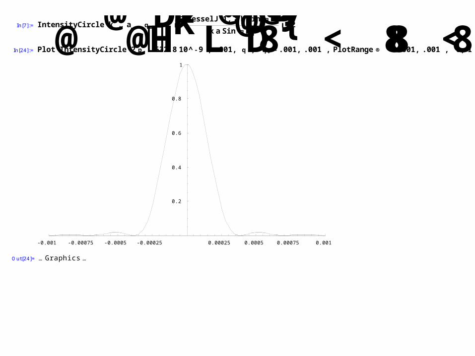
In[7]:= IntensityCircle@k_, a_, q_D:=ik2 BesselJ@1, akSin@qDDkaSin@qDy{^2In[24]:= Plot@IntensityCircle@2 pH632.810^-9L, .001, qD,8q, - .001, .001<, PlotRange®88- .001, .001<,80, 1<<D
-0.001 -0.00075 -0.0005 -0.00025 0.00025 0.0005 0.00075 0.001
0.2
0.4
0.6
0.8
1
Out[24]= … Graphics …
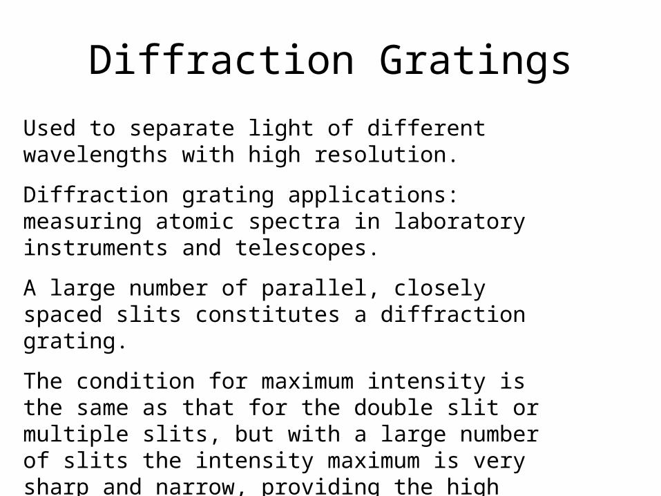
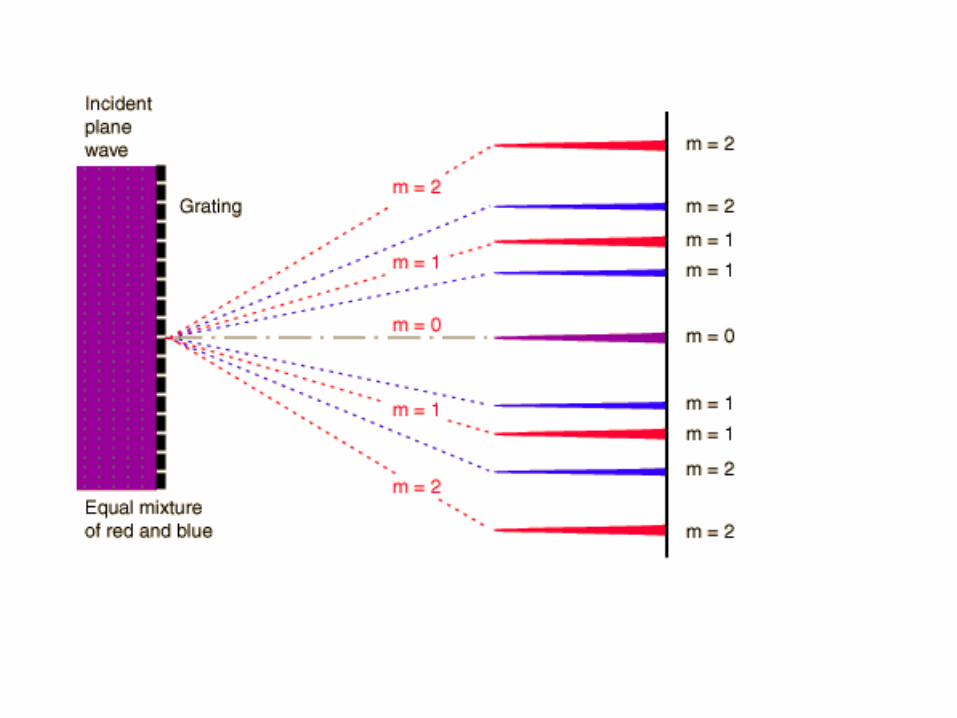
Diffraction Gratings
Used to separate light of different wavelengths with high resolution.
Diffraction grating applications: measuring atomic spectra in laboratory instruments and telescopes.
A large number of parallel, closely spaced slits constitutes a diffraction grating.
The condition for maximum intensity is the same as that for the double slit or multiple slits, but with a large number of slits the intensity maximum is very sharp and narrow, providing the high resolution for spectroscopic applications.

Transmission Grating
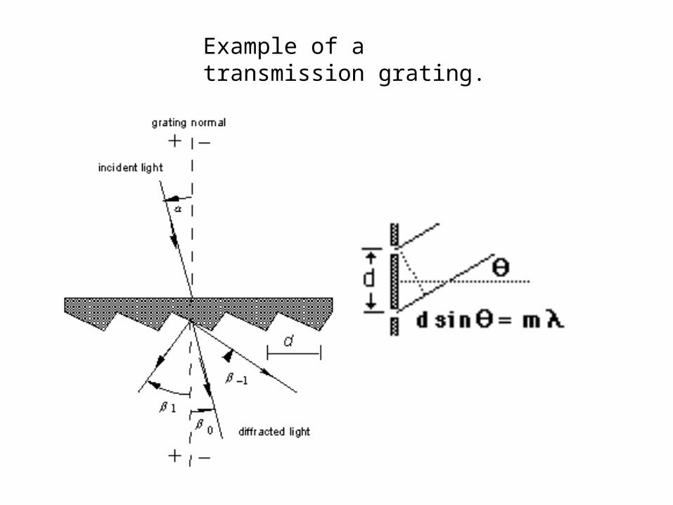
Example of a transmission grating.
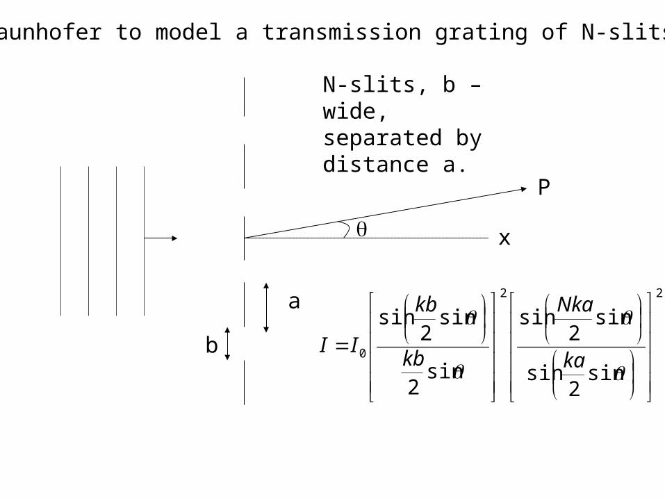
Use Fraunhofer to model a transmission grating of N-slits
x
P
a
b
N-slits, b – wide, separated by distance a.
22
0
sin2
sin
sin2
sin
sin2
sin2
sin
ka
Nka
kb
kb
II
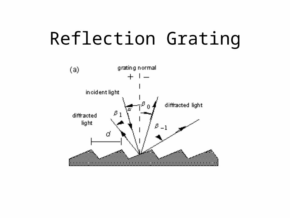
Reflection Grating
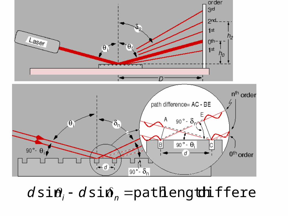
differencelength path sinsin ni dd
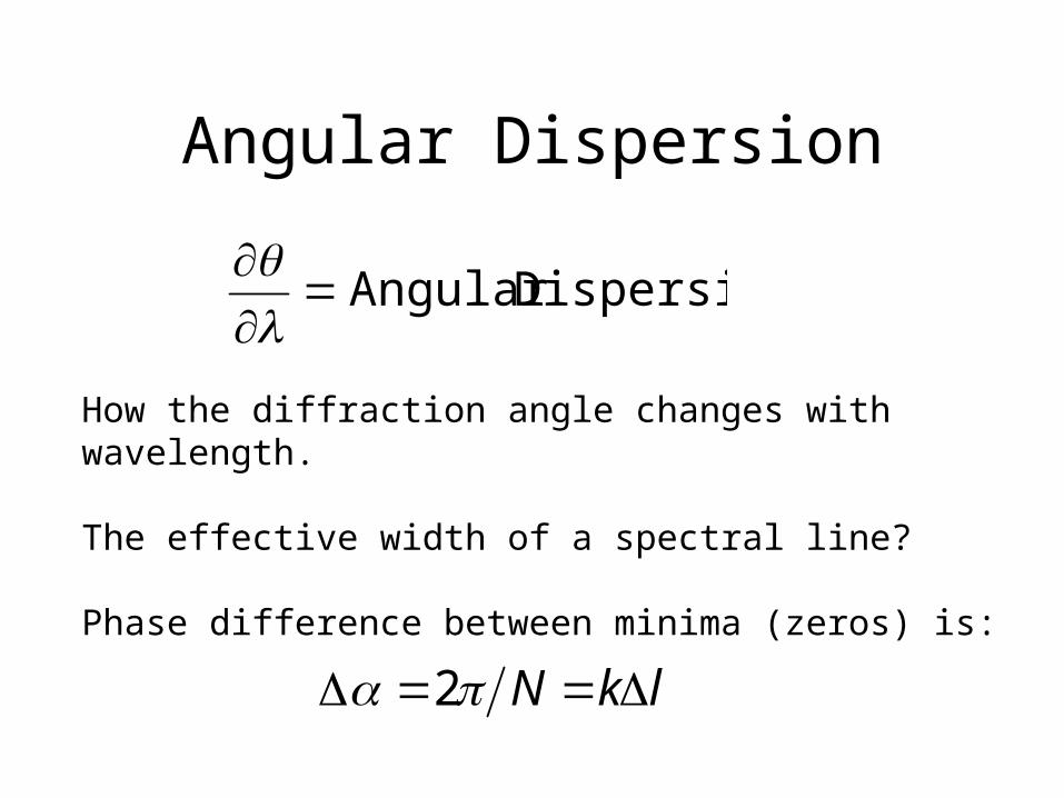
Angular Dispersion
How the diffraction angle changes with wavelength.
The effective width of a spectral line?
Phase difference between minima (zeros) is:
DispersionAngular
lkN 2
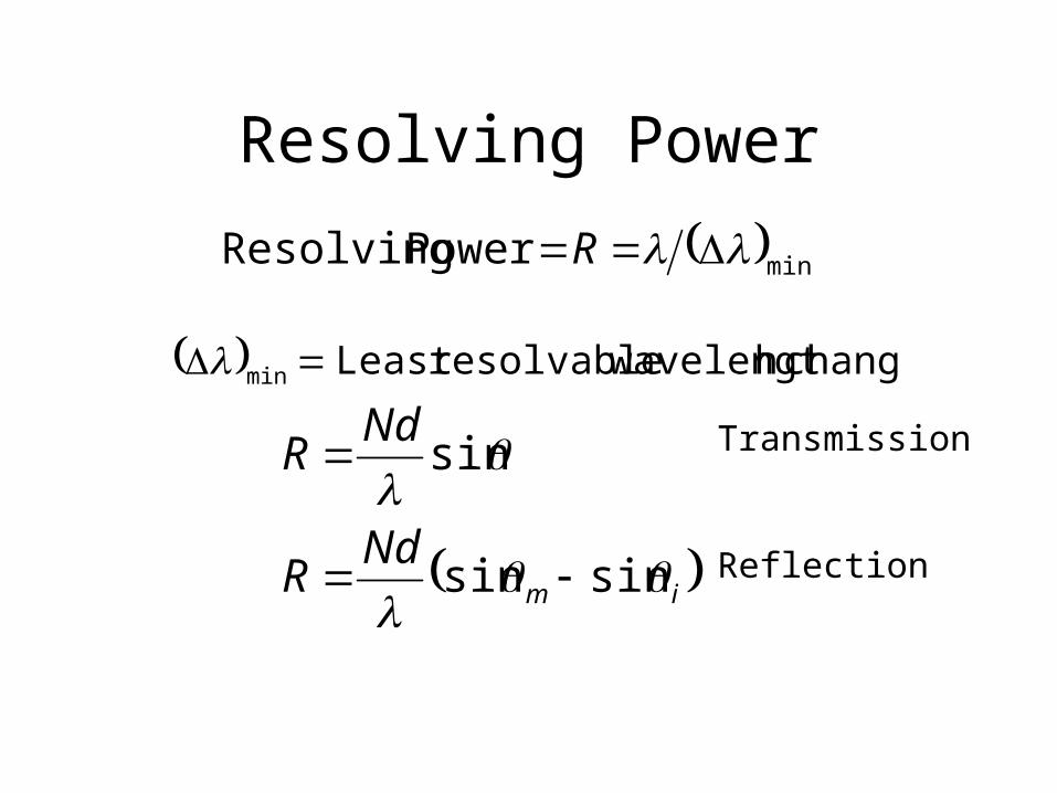
Resolving Power
minPower Resolving R
changeh wavelengtresolvableLeast min
im
NdR
NdR
sinsin
sin
Transmission
Reflection
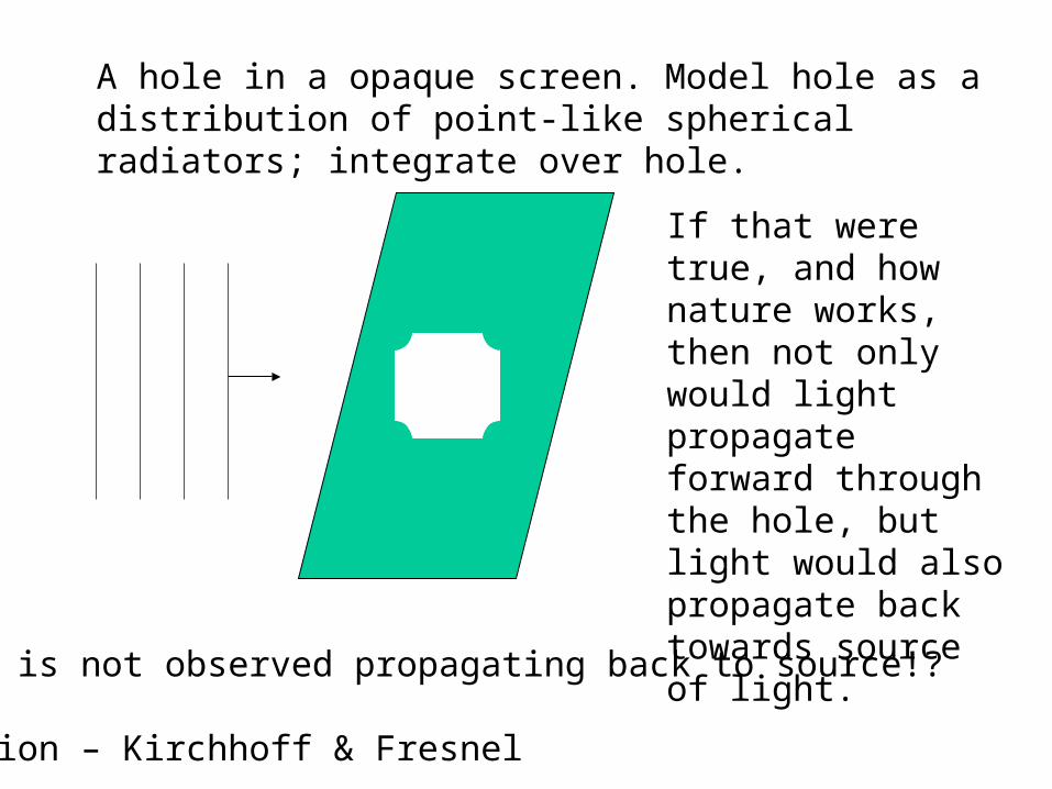
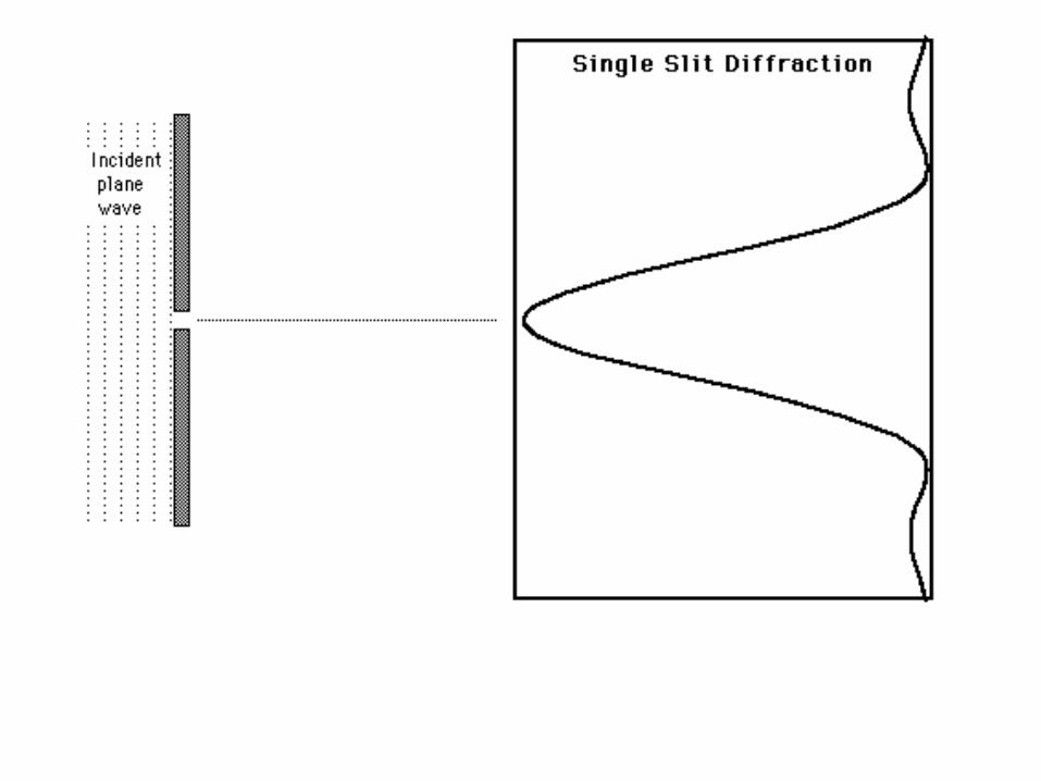
A hole in a opaque screen. Model hole as a distribution of point-like spherical radiators; integrate over hole.
If that were true, and how nature works, then not only would light propagate forward through the hole, but light would also propagate back towards source of light.
Light is not observed propagating back to source!?
Solution – Kirchhoff & Fresnel
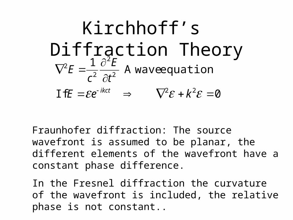
Kirchhoff’s Diffraction Theory
0 If
equation waveA 1
22
2
2
22
keE
t
E
cE
ikct
Fraunhofer diffraction: The source wavefront is assumed to be planar, the different elements of the wavefront have a constant phase difference.
In the Fresnel diffraction the curvature of the wavefront is included, the relative phase is not constant..
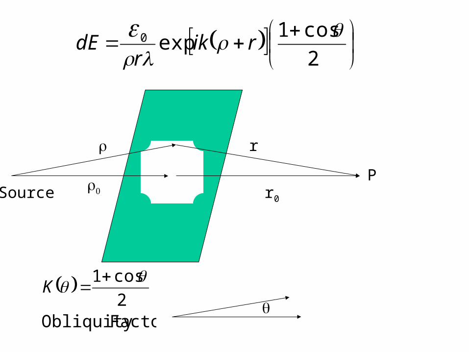
r0
r
SourceP
2
cos1exp0
rikr
dE
FactorObliquity 2
cos1 K
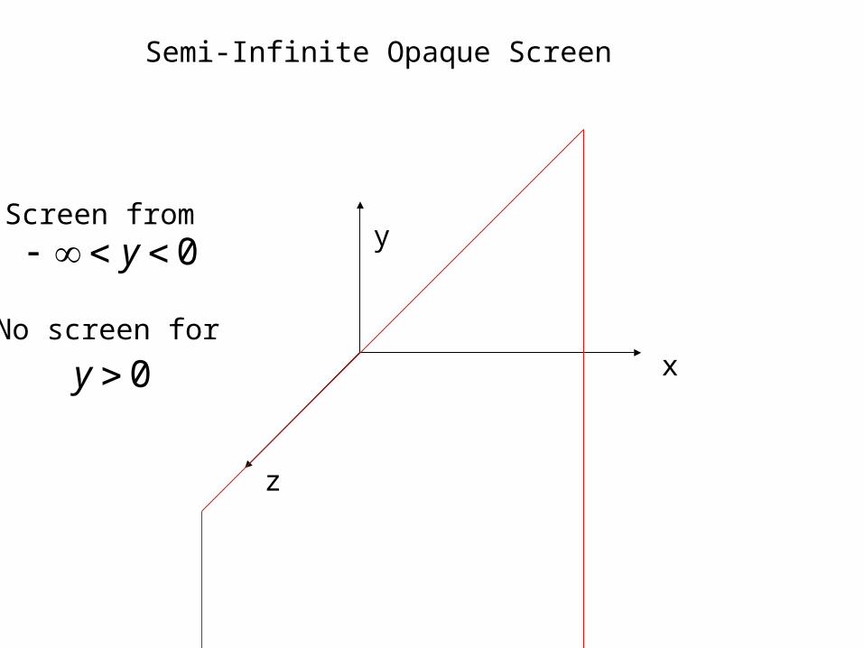
Semi-Infinite Opaque Screen
x
y
z
Screen from
0 y
No screen for
0y
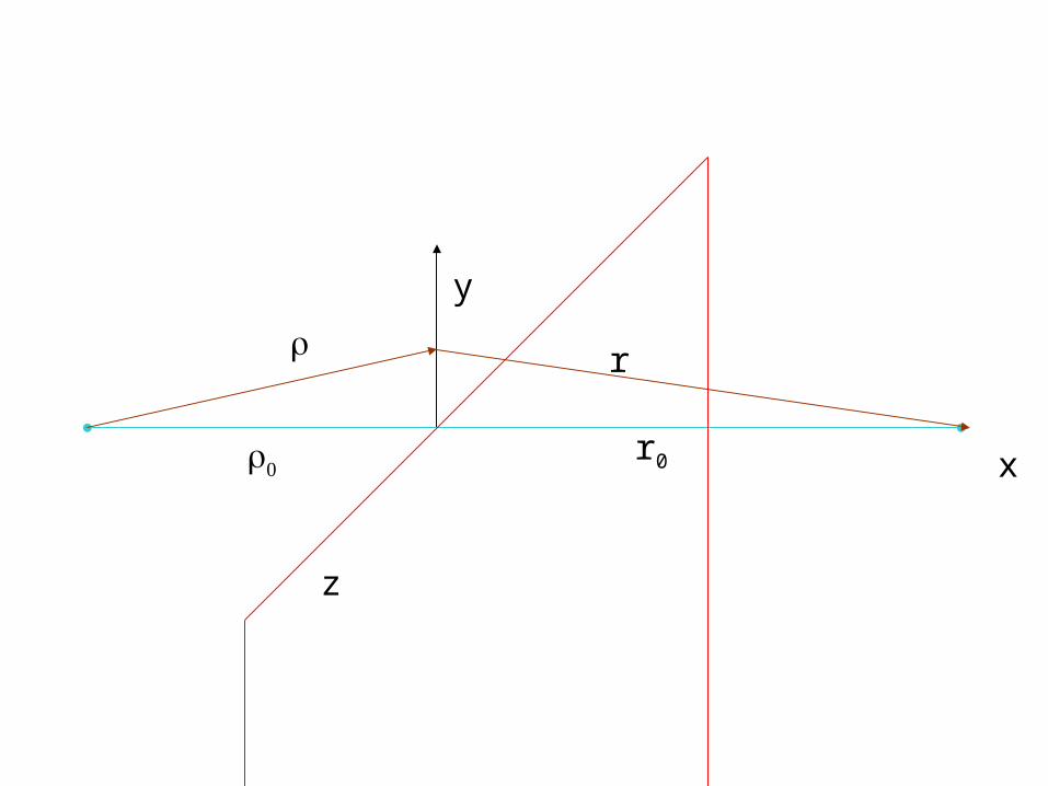
x
y
z
r0
r
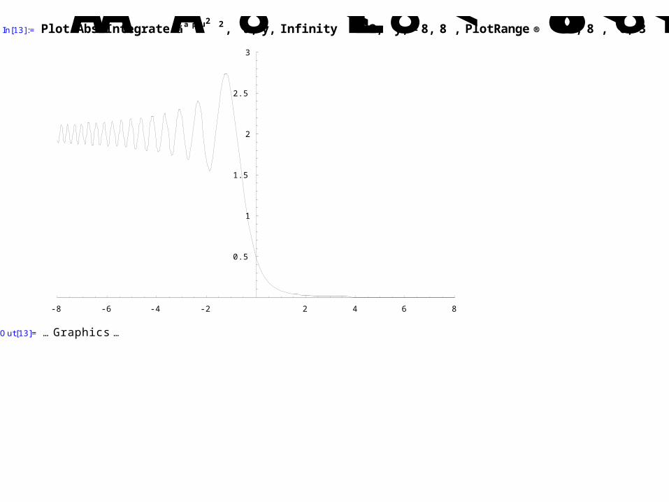
In[13]:= PlotAAbsAIntegrateAãä pu2‘2,8u, y, Infinity<EE2,8y, - 8, 8<, PlotRange®88- 8, 8<,80, 3<<E
-8 -6 -4 -2 2 4 6 8
0.5
1
1.5
2
2.5
3
Out[13]= … Graphics …
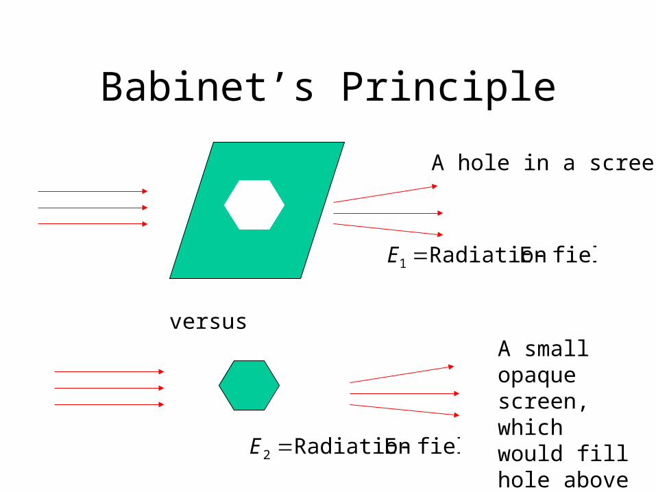
Babinet’s Principle
versus
A hole in a screen
A small opaque screen, which would fill hole above
fieldERadiation 1 E
fieldERadiation 2 E
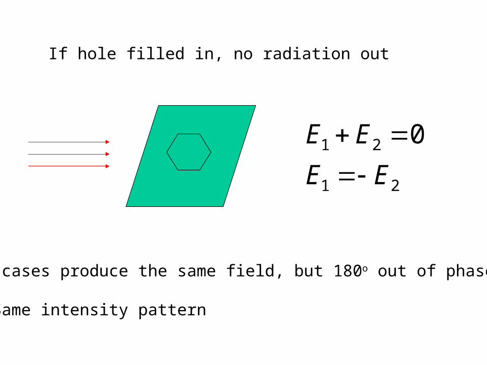
If hole filled in, no radiation out
21
21 0
EE
EE
Two cases produce the same field, but 180o out of phase.
=> Same intensity pattern


![Generation of incoherent Cherenkov diffraction radiation in ......beam size measurements using diffraction radiation from dielectric slits [10]. The ChDR radiator, described in more](https://img.pdfslide.us/doc/110x75/602e7a78224a437bf0056885/generation-of-incoherent-cherenkov-diffraction-radiation-in-beam-size-measurements.jpg)