Embed Size (px)
Citation preview

Second Series December, Igz7 Vol. 3o, Xo. 6
THE
PHYSICAL REVIEW
DIFFRACTION OF ELECTRONS BY A CRYSTAL OF NICKEL
BY C. DAVISSON AND L. H. GHRMER
ABSTRACT
The intensity of scattering of a homogeneous beam of electrons of adjustablespeed incident upon a single crystal of nickel has been measured as a function ofdirection. The crystal is cut parallel to a set of its I 111j-planes and bombardment isat normal incidence. The distribution in latitude and azimuth has been determinedfor such scattered electrons as have lost little or none of their incident energy.
Electron beams resulting from diffraction by a nickel crystal. —Electrons of theabove class are scattered in all directions at all speeds of bombardment, but atand near critical speeds sets of three or of six sharply defined beams of electrons issuefrom the crystal in its principal azimuths. Thirty such sets of beams have been ob-served for bombarding potentials below 370 volts. Six of these sets are due to scatter-ing by adsorbed gas; they are not found when the crystal is thoroughly degassed. Ofthe twenty-four sets due to scattering by the gas-free crystal, twenty are associatedwith twenty sets of Laue beams that would issue from the crystal within the range ofobservation if the incident beam were a beam of heterogeneous x-rays, three that occurnear grazing are accounted for as diffraction beams due to scattering from a single
I 111j-layer of nickel atoms, s,nd one set of low intensity has not been accounted for.2lfissing beams number eight. The~ are beams whose occurrence is required by thecorrelations mentioned above, but which have not been found. The intensitiesexpected for these beams are all low.
The syacing factor concerned in electron diffraction by a nickel crystal. —Theelectron beams associated with Laue beams do not coincide with these beams inposition, but occur as if the crystal were contracted normally to its surface. The spac-ing factor describing this contraction varies from 0.7 for electrons of lowest speed to0.9 for electrons whose speed corresponds to a potential difference of 370 volts.
Bggivalent crave-lengths of the electron beams may be calculated from the diffrac-tion data in the usual way. These turn out to be in acceptable agreement with thevalues of h/mv of the undulatory mechanics.
Di6'raction beams due to adsorbed gas are observed except when the crystalhas been thoroughly cleaned by heating. Six sets of beams of this class have beenfound; three of these appear only when the crystal is heavily coated with gas; theother three only when the amount of adsorbed gas is slight. The structure of the gasfilm giving rise to the latter beams has been deduced.
' 'HE investigation reported in this paper was begun as the result of anaccident which occurred in this laboratory in April 1925. At that time
we were continuing an investigation, first reported in 1921,' of the dis-tribution-in-angle of electrons scattered by a target of ordinary (poly-
' Davisson 8t: Kunsman, Science 64, 522, (1921').
705

706 C. DA. VISSOE AND I.. H. GERBER
crystalline) nickel. During the course of this work a liquid-air bottle explodedat @ time when the target was at a high temperature; the experimental tubewas broken, and the target heavily oxidized by the inrushing air. The oxidewas eventually reduced and a layer of the target removed by vaporization,but only after prolonged heating at various high temperatures in hydrogenand in vacuum.
When the experiments were continued it was found that the distribution-in-angle of the scattered electrons had been completely changed. Specimencurves exhibiting this alteration are shown in Fig. 1. These curves are allfor a bombarding potential of 75 volts. The electron beam is incident onthe target from the right, and the intensities of scattering in differentdirections are proportional to the vectors from the point of bombardmentto the curves. The upper curves (for different angles of incidence) arecharacteristic of the target prior to the accident. They are of the type
SCATTERING OF 7& VOLT ELECTRONS FROMA BLOCK OF NICKEL (MANY SMALL cRYsTAL5)
SCATTERING OF 75 VOLT ElECTRONS FROMSEVE RAI LARGE NICKEL CRYSTALS
I ig. 1. Scattering curves from nickel before and after crystal growth had occurred.
described in the note in "Science" in 1921, and are similar to curves that havebeen obtained for nickel in four or five other experiments. The lower curves—obtained after the accident —were the first of their sort to be observed. Thismarked alteration in the scattering pattern was traced to a re-crystallizationof the target that occurred during the prolonged heating. Before the accidentand in previous experiments we had been bombarding many small crystals,but in the tests subsequent to the accident we were bombarding only a fewlarge ones. The actual number was of the order of ten.
It seemed probable from these results that the intensity of scatteringfrom a single crystal would exhibit a marked dependence on crystal direction,and we set about at once preparing experiments for an investigation of thisdependence. We must admit that the results obtained in these experimentshave proved to be quite at variance with our expectations. It seemed to uslikely that strong beams would be found issuing from the crystal along what
DIFFRACTION OF ELECTRONS 8 Y A NICKEL CRYSTAL 707
may be termed its transparent directions —the directions in which the atomsin the lattice are arranged along the smallest number of lines per unit area.Strong beams are indeed found issuing from the crystal, but only when thespeed of bombardment lies near one or another of a series of critical values,and then in directions quite unrelated to crystal transparency.
The most striking characteristic of these beams is a one to one cor-respondence, presently to be described, which the strongest of them bearto the Laue beams that would be found issuing from the same crystal if theincident beam were a beam of x-rays. Certain others appear to be analogues,not of Laue beams, but of optical diffraction beams from plane reHectiongratings —the lines of these gratings being lines or rows of atoms in thesurface of the crystal. Because of these similarities between the scatteringof electrons by the crystal and the scattering of waves by three- and two-dimensional gratings a description of the occurrence and behavior of theelectron diffraction beams in terms of the scattering of an equivalent waveradiation by the atoms of the crystal, and its subsequent interference, is notonly possible, but most simple and natural. This involves the association ofa wave-length with the incident electron beam, and this wave-length turnsout to be in acceptable agreement with the value h/mn of the undulatorymechanics, Planck's action constant divided by the momentum of theelectron.
That evidence for the wave nature of particle mechanics would be foundin the reaction between a beam of electrons and a single crystal was pre-dicted by Elsasser' two years ago—shortly after the appearance of L. deBroglie's original papers on wave mechanics. Elsasser believed, in fact, thatevidence of this sort was already at hand in curves, published from theseLaboratories, showing the distribution-in-angle of electrons scattered by atarget of polycrystalline platinum. We should like to agree with Elsasserin his interpretation of these curves, but are unable to do so. The maximain the scattering curves for platinum are of the type of the single maximumin the curves for nickel shown in the upper half of Fig. 1, and are, we believe,unrelated to crystal structure.
Preliminary announcement of the main results contained in this paperwas made in "Nature" for April 16, 1927. In the present article we give amore complete account of the experiments and additional data.
THE APPARATUs
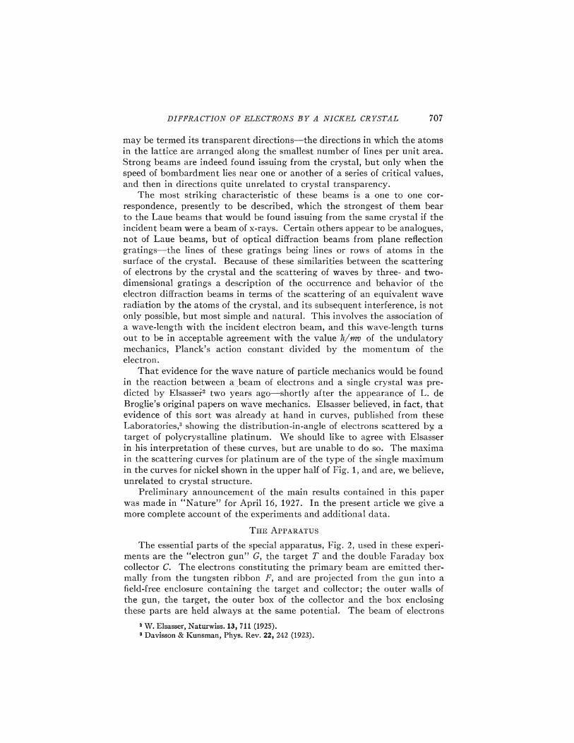
The essential parts of the special apparatus, Fig. 2, used in these experi-ments are the "electron gun" G, the target T and the double Faraday boxcollector C. The electrons constituting the primary beam are emitted ther-mally from the tungsten ribbon Ii, and are projected from the gun into afield-free enclosure containing the target and collector; the outer walls ofthe gun, the target, the outer box of the collector and the box enclosingthese parts are held always at the same potential. The beam of electrons
' %.Elsasser, Naturwiss. 13, 711 (1925).' Davisson Bz Kunsman, Phys. Rev. 22, 242 (1923).
708 C. DAVISSOE AND I.. II; GERBER
meets the target at normal incidence. High speed electrons scattered withinthe small solid angle de6ned by the collector opening enter the inner box ofthe collector, and from thence pass through a sensitive galvanometer.Electrons leaving the target with speeds appreciably less than the speedof the incident electrons are excluded from the collector by a retarding
G.A. I
/
~/~II/II~I~I~IIII~I~I~III~IIII et;":/JYJJi'ul/1%) . /WiliAJ//VJ
I/Y/'/'////V/'//'l ~V,AV & /
//
//
) 0///
/
/
~ll&j&l& l&l~l~l&l~l~l~l&l&III&1&I&l&it~ill
Fig. 2. Cross-sectional view of the experimental apparatus —glass bulb not shown.
potential between the inner and outer boxes. The angle between the axisof the incident beam and the line joining the bombarded area with theopening in the collector can be varied from 20 to 90 degrees. Also the targetcan be rotated about an axis that coincides with the axis of the incident beam.It is thus possible to measure the intensity of scattering in any direction in
COLLECTORLEAD~
COLLECTORreEAPINGS&
ge-".'
QUARTZINSULATION
5XZZ5ZIXEEP
QUARTZTUBING
~PYREX BEAD
DETAIL OFCOLLECTOP, t
DETAIL OFELECTRON GUN, G
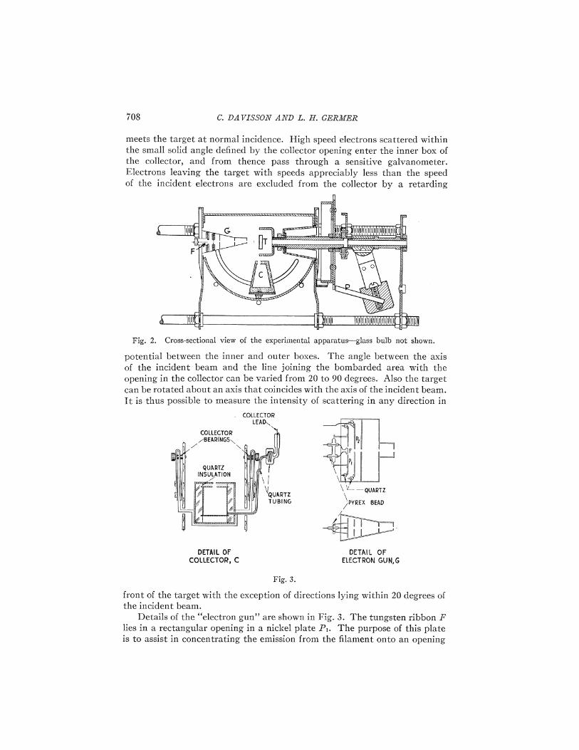
Fig. 3.
front of the target with the exception of directions lying within 20 degrees ofthe incident beam.
Details of the "electron gun" are shown in Fig. 3. The tungsten ribbon Ii
lies in a rectangular opening in a nickel plate I'~. The purpose of this plateis to assist in concentrating the emission from the 6.lament onto an opening

DIFFRACTION OF ELECTRONS BY A, NICEEL CRYSTAL 709
in the parallel plate I'2. This is accomplished by making the potential of I'&
slightly more negative than that of the filament. The potential of P2 relativeto that of the filament is adjusted ordinarily to a rather high positive value.
The opening in I'2 is circular and slightly more than 1 mm in diameter.Some of the electrons passing through this opening continue on throughapertures in a series of three plates that are at the same potential as theouter walls of the gun. It is the difference between this potential and thatof the filament which determines the speed of the emergent beam. The firsttwo of these apertures are 8 mm apart and are 1 mm in diameter; the diameterof the third is slightly greater. The geometry of these parts is such as toinsure a well defined emergent beam relatively free from low speed secondaryelectrons. The gun was tested in a preliminary experiment, and was foundto give a homogeneous beam. The distance from the end of the gun to thetarget is 7 mm.
The two parts of the collector (Fig. 3) are insulated from one another byblocks of clear quartz. The openings in the outer and inner boxes are circular,
—- ss
I UIi&li l&l. ~il&lilil&l&i&l&l&lililil&liliiil„.'illi&lil&l
--5
—-7
I
,iliil& ilil)liiil&lil&liiiiil)l)iilililililiiil~', ig~iiti t
J
Fig. 4. Outside view of the experimental apparatus —glass bulb not shown —0.7 actual size.
their diameters being 1.0 mm and 2.0 mm respectively. These openings weremade as near as possible to the side of the box adjacent to the gun in orderto reduce to a minimum the unexplored region about the incident beam.I'he collector is suspended by arms from bearings outside the enclosing box(Fig. 4), and is free to rotate about a horizontal axis through the bombardedarea and normal to the incident beam. The angular position of the collectoris varied by rotating the whole tube, which is sealed from the pumps, aboutthis axis. The lead to the inner box must be especially shielded from straycurrents; it is enclosed in small quartz tubing from the point at which itleaves the outer box to the seal at which it leaves the tube. The distancefrom the bombarded area to the opening in the outer box is 11 mm.
The target is a block of nickel 8XSX3 mm cut from a bar in whichcrystal growth had been induced by straining and annealing. The orienta-tions of the largest crystals in the bar were determined by an examinationof the optical rejections from crystal facets that had been developed by

710 C. DA UISSON AND L. H. GERMEN
etching. A cut was then made through one of the crystals approximatelyparallel to a set of its I111}-planes. One of the surfaces so exposed waspolished, etched, examined and corrected, and became eventually the faceof the target.
No particular care was taken in preparing the target to avoid strainingor damaging the crystal. The cutting was done with a jeweler's saw; holeswere drilled through the ends of the block, and nickel wires were passedthrough these to serve as supports. After this rather rough usage the targetwas heated in an auxiliary tube to near its melting point without its showingany indication of recrystallization.
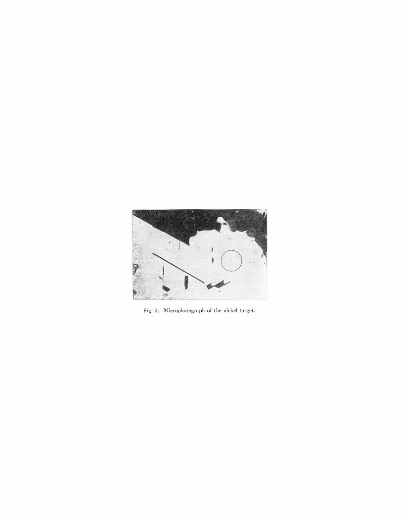
The effect of etching a nickel crystal, either chemically or by vaporization,is to develop its surface into sets of facets parallel to its principal planes.Those parallel to the I 111}-planes are developed most readily, but we havealso observed others parallel to the I110}-planes.' Four sets of the pre-dominant I111}-facets are, in general, exposed on a plane surface. If oneof these is parallel to the general plane of the surface, as in the case of our
' '!3
Fig. 5. Microphotograph of the nickel target.
target, the other sets have normals lying ZO degrees above the general planeof the surface and equally spaced in azimuth about the normal to the first set.
A microphotograph of the face of the target is shown in Fig. 5. Theillumination is at normal incidence, and the large crystal shows white onaccount of the strong reflection from the I 111 }-facets lying in its surface.That these facets make up nearly the whole of the surface seems probablefrom the fact that in the visual examination of the crystal the reflections fromthe lateral facets were very weak. This conclusion may not, however, bestated without reservation, as the weakness of these reflections may indicatemerely that some dimension of the individual facets is small compared withoptical wave-lengths. The regions appearing black in the photograph aremade up of crystals having no facets parallel to the surface. Those includedin the large crystal and others adjacent to it are twinned with the mainstructure. The area selected for bombardment is shown enclosed in a circle.
4 See also Potter and Sucksmith, Nature 119,924 (1927), who found {100I -facets.

DIFFRACTION OIl ELECTRONS BY A NICEBL CRYSTAL 7ii
The target was mounted in a holder from which it was insulated, andthe holder was fixed to the end of a hollow shaft mounted in bearings.A small tungsten filament mounted back of the target (not shown in Fig. 2)supplies electrons for heating the target by bombardment. Leads from thetarget and from this filament pass out through the hollow shaft and areconnected through platinum brush contacts to other leads which are carriedthrough seals in the'tube.
The mechanism for rotating the target is shown in Figs. 2 and 4. Whenthe tube is rotated counter-clockwise about the collector axis, to bring thecollector into range in front of the target, the molybdenum plunger p (at-tached to a heavy pendulum) passes through an opening in a toothed wheel(attached to the shaft) and engages with a milled edge of a strip of molyb-denum that is attached to the frame. The wheel and the target are thenlocked to the frame. When the tube is rotated clockwise until the mainor longitudinal axis of the tube has passed slightly beyond the horizontal,the plunger disengages from the milled edge but still remains within theopening in the toothed wheel. The pendulum has a second degree of freedom(it revolves about a fixed hollow shaft coaxial with the shaft carrying thetarget) so that, by rotating the tube about its main axis, the pendulum andengaged wheel are rotated relative to the frame. The range of this rotationis only 20' or 30', but by rotating the tube slightly further in the clockwisedirection about the collector axis the plunger is disengaged from the wheel,and can be moved, by rotation again about the main axis, to a differentopening in the toothed wheel. By these operations the target can be workedthrough any angle. Its azimuth is read from a scale ruled on the wheel.This scale and that for reading the position of the collector are shown inFig. 4. The bearings throughout the tube, with the exception of one nickelon nickel bearing, are either molybdenum on molybdenum, or molybdenumon nickel.
PREPARATION OF THE TUBE
The metal parts of the tube were preheated to 1000'C in a vacuum oven,and were then assembled and sealed into the bulb with the least possibledelay. The bulb is of Pyrex and has sealed to it two auxiliary tubes, onecontaining cocoanut charcoal, and the other a misch metal vaporizer. Thislatter consists of a small pellet of misch metal attached to a molybdenumplate anode which may be bombarded from a nearby tungsten filament.The thermal contact between the pellet and the plate is reduced by theinterposition of a narrow strip of molybdenum, so that the misch metal maybe vaporized only by raising the plate to a very high temperature. The mischmetal is vaporized when the pumping is nearly completed, and various ofits constituents form solid compounds with the residual gas, thus improvingand maintaining the vacuum.
During the pumping, which lasted several days, the tube itself and thetubing connecting it with the pumps were baked for hours at a time at 500'C,and the side tube containing charcoal was baked at an even higher tem-perature —about 550'C. This baking was alternated with heating by bom-

C. DAVISSOX AND L. B; GER3EER
bardment of such of the metal parts as could be reached from the filaments.The target in particular was heated several times to a temperature at whichit vaporized freely. The tube was sealed from the pumps with the targetat a high temperature, and the charcoal at 400 or 500'C and cooling. Thepressure in the tube at the time was 2 or 3&(10 ' mm of mercury. As soonas the tube containing charcoal had cooled sufficiently it was immersed inliquid air. No means were provided for measuring the pressure of the gasin the tube after sealing from the pumps, but from experience with similartubes in which such measurements could be made we judge that its equilib-rium value was 10 8 mm of mercury or less. The pumping equipment con-sisted of a three stage Gaede diffusion pump backed by a two stage oil pump.
THE CRYSTALIt is important to have a clear picture of the arrangement of atoms
presented to the incident beam by the crystal. The nickel crystal is of the
APPANGFMENT OF ATOM5 AND
DEStGNATION OF AZ}MUTHS
No, o/"~ /g)X'/g)1 ~"'Ot 0 O~
{IfO) = /Q2% /Q2% /QZ~ = {110{} I I
/I~'/I~'/~„,
«~op
Fig. 6.
face-centered cubic type. The I 111}-plane is the plane of densest packing,and in this plane the atoms have a triangular arrangement. Looking directlydownward onto a crystal cut to this plane (Fig. 6) one sees the atoms of thesecond plane below the centers of alternate triangles of the first plane, andthe atoms of the third plane below the centers of the remaining triangles.The atoms of the fourth plane are below those of the first. The lines joiningany second-layer atom with the three nearest first-layer atoms are I 110}-directions in the crystal, and the lines joining it with the three next-nearestsurface atoms are the orthogonal I100}-directions. It will be convenient torefer to the azimuths of these latter directions as I100}-azimuths. Theazimuths of the I 110 }-directions are also those of the three lateral I 111directions, already referred to, and we shall designate these as I 111azimuths. We need also a designation for the azimuths that bisect thedihedral angles between adjacent members of the two sets already specified.There are six such azimuths and they will be referred to as I 110 }-azimuths.
DIFFRACTION OF ELECTRONS BY A NICKEL CRYSTAL 713
It follows from the trigonal symmetry of the crystal that if the intensityof scattering exhibits a dependence on azimuth as we pass from a I 100}-azimuth to a next adjacent I 111}-azimuth (60'), the same dependence mustbe exhibited in the reverse order as we continue on through 60' to the nextfollowing I 100 }-azimuth. Dependence upon azimuth must be an evenfunction of period 2vr/3.
DISTRIBUTION OF SPEEDS AMONG SCATTERED ELECTRONS
The electrons leaving the target in any given direction appear alwaysto have speeds that are distributed in one of two ways, depending uponwhether the direction lies within or outside a diffraction beam. In the latter
CURVE ITOTAL SCATTERING
Cr.O
O
CURVE IK8EAM SCATTERING
CURVE II
BACKGROUND
SCATTERING
(INTERP0LATED)
IO 20 30 40 50COLLECTOR POTENT)AL
$0 70
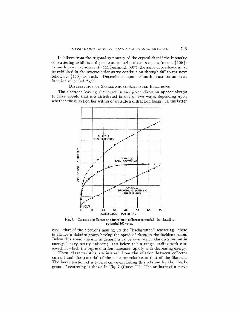
Fig. 7. Current to collector as a function of collector potential —bombardingpotential 160 volts.
case—that of the electrons making up the "background" scattering —thereis always a definite group having the speed of those in the incident beam.Below this speed there is in general a range over which the distribution inenergy is very nearly uniform; and below this a range, ending with zerospeed, in which the representation increases rapidly with decreasing energy.
These characteristics are inferred from the relation between collectorcurrent and the potential of the collector relative to that of the filament.The lower portion of a typical curve exhibiting this relation for the "back-ground" scattering is shown in Fig. 7 (Curve II). The ordinate of a curve

C. DAUISSON AND L. H. GERBER
of this sort is not, of course, an actual measure of the number of electronsentering the outer box with sufficient energy to reach the inner box. Onaccount of the distortion of the field about the openings the probability thatan electron entering the outer box with just sufficient energy to reach thewalls of the inner box will actually do so is vanishingly small; the saturationcurrent due to electrons of a given speed is attained only when the potentialof the inner box is somewhat higher than that corresponding to their speed.The rounding off of the current-voltage curve at the top of the initial riseis due to some extent to this cause.
For this reason the group of high speed, or full speed, electrons is morenearly homogeneous than would be inferred from the current-voltage curveif no account were taken of this distortion. It seems probable, in fact, thatthe distortion accounts almost completely for the rounding off of the curve,and that the group is as nearly homogeneous as is permitted by the dropin potential along the filament and the initial speeds of the emitted electrons.This view is strongly supported by the observations of Becker, ' Brown andWhiddington, ' Sharman, ' and Brinsmade' on the magnetic spectrum ofelectrons scattered by metals, and by similar curves obtained by Farns-worth. '
Within a diffraction-beam the distribution-in-speed is somewhat different.There is again a definite group of full speed electrons, but speeds just inferiorto the maximum have much greater representation than among the back-ground electrons. This is inferred from curve III in Fig. 7 which is repre-sentative of the current-voltage relation for electrons of this class. We shallreturn in a later section to a further consideration of the curves in this figure.
In studying the distribution in direction of the scattered electronsmeasurements have been confined, as nearly as possible, to the group of fullspeed electrons. The potential of the collector is set just high enough toadmit all of this group. The ratio of collector to bombarding current is thenof the order 10 ', so that, by using bombarding currents of the order 10ampere, collector currents are obtained that are easily measurable with asensitive galvanometer. The total integrated current of full speed scatteredelectrons is from a tenth to a twentieth as great as the current of the incidentbeam.
DISTRIBUTION OF DIRECTIONS AMONG FULL SPEED SCATTERED ELECTRONS
The current of full speed electrons entering the collector is proportionalto the current incident upon the target and is otherwise a function of thebombarding potential and of the latitude and azimuth of the collector.Three simple types of measurement are thus possible in each of which twoof the independent variables are held constant and the third is varied. Whenbombarding potential and azimuth are fixed and exploration is made in
~ J.A. Becker, Phys. Rev. 23, 664 (1924).6 D. Brown and R. Whiddington, Nature 119,427 (1927).' C. F.Sharman, Proc. Camb. Phil. Soc. 23, 523 (1927),8 J.B.Brinsmade, Phys. Rev. 30, 494 (1927).9 H. E.Farnsworth, Phys. Rev. 25, 41 (1925).

DIFFRACTION OP ELECTRONS BY A NICKEL CRYSTAL
latitude a dependence of current upon angle is observed which is generallyof the form shown in Fig. 8; the current of scattered electrons is zero inthe plane of the target and increases regularly to a highest value at the limitof observations —colatitude 20'. This type of dependence upon angle isessentially the same as is observed when the target is of ordinary nickel—made up of many small crystals.
When bombarding potential and latitude angle are Axed and explorationis made in azimuth a variation of collector current is always observed, andthis exhibits always the three-fold symmetry required by the symmetry ofthe crystal. The curves show in general two sets of maxima —a set of threein the I111I-azimuths, and a set of three of different intensity in the I 100I-azimuths. These crests and troughs in the azimuth curves are usually notpronounced.
In the third method of observation the position of the. collector is Axedin one of the principal azimuths at one after another of a series of colatitude
30
45'
t'po
TgpcET (I I lI AZlMUTH33 VOLTS
Fig. 8. Typical coiatitude scattering curve for the single nickel crystal.
angles, and at each such setting the current to the collector is observed as afunction of bombarding potential. It would be desirable in making observa-tions of this sort to keep constant the current in the incident beam but, asthere is no ready means of doing this, the current to the plate P2 (Fig 3)is kept constant instead. Beginning at colatitude 20' a series of such ob-servations is made, over a predetermined voltage range, at 5' intervals tocolatitude 80' or 85'. A portion of a set of curves constructed from suchdata is shown in Fig. 9.
The general trend of a single one of these curves is not significant as it isdetermined in part by variation with voltage of the bombarding current.The relative displacements among them, however, are significant as theyindicate departures from the simple type of colatitude curve shown in Fig. 8.From the curves in Fig. 9 we see, for example, that the colatitude curvesfor bombarding potentials near 55 volts are characterized by exceptionalintensities at colatitude angles near 50'. The data for constructing colatitude

C. DAVISSOX AND L. H. GEROME
curves for particular bombarding potentials are taken directly from suchcurves as those of' Fig. 9, or the features in these latter curves are used as
I- 350
(~CV COO
4J
C)V-
70
VOLTS
35 40 45 50 55 &0 $5BOM8APOING POTENTIAL
70 75
Fig. 9. Curves of collector current vs. bombarding potential —showing the developmentof the "54 volt beam "Azimu. th {1111.
30
SO
75
(IOO) AZIMUTH TARGET (II lj AZIMUTH
Fig. &0. Scattering curves showing the occurrence of the "54 volt" electron beamand the "65 volt" electron beam. (On each scattering curve is indicated the
bombarding potential in volts. )
a guide to voltage-colatitude ranges requiring special study. This methodhas been employed in exploring the principal azimuths in the range from

DIFIlRA. CTIOX OP ELECTRONS B1 A. NICKEL CRY'STOL 717
15 to 350 volts, and two other azimuths, to be specified later, over the rangefrom 200 to 300 volts. Every feature of the sort shown in Fig. 9 has beeninvestigated.
The unusual and signi6. cant feature revealed by the curves of Fig. 9is exhibited again in the set of colatitude curves on the right in Fig. 10.Ke see a slight hump at 60' in the colatitude curve for 40 volts, and observethat as the bombarding potential is increased this hump develops into astrong spur which reaches a maximum development at 54 volts in colatitude
8=447=$5Volts
$Z ~C3
)0 ~
8 8
8= 507'= 54 Volts
QJ QJ'
I I I I i
0' 30' R' 30' 120 lX l%' 210 240 270 XS 530' %0AZIMUTH ANGLE
Fig. 11. Azimuth scattering curves through the "54-volt" electron beam andthrough the "65-volt" electron beam.
50', then decreases in intensity and Anally disappears at about 66 volts incolatitude 40'.
A section in azimuth through the center of this spur in its maximumdevelopment is shown in the lower curve of Fig. 11. The spur is sharpin azimuth as well as in latitude and is one of a set of three spurs asthe symmetry of the crystal requires. The smaller peaks in the I100I-azimuth are sections of a similar set of spurs that attains its maximumdevelopment at 65 volts in colatitude 44'. A complete se& of colatitude curvet. :.&

C. DAVISSOE AND L. H. GERMS
for one of these spurs is shown on the left in Fig. 10. The upper curve inFig. 11 is an azimuth curve through the peaks of these 65 volt spurs. Thesmall peaks in the {111I-azimuth are the remnants of the "54 volt" spurs.
The colatitude angles at which the various spurs of a single set arestrongest are found not to have exactly the same values. This is due appar-ently to imperfect alignment of the normal to the crystal planes and theaxis of rotation of the target. In each of several sets that have been studiedthese angles are expressed by the formula 0=0,+60 cos (@—$0), whereOp is a constant for a given set and is taken to represent the colatitude angleat which all spurs in the set would be strongest if the alignment were perfect,and 69 and $0 are constants that have the same values for all sets, 2' and 1'respectively. This is taken to mean that the axis of rotation is displacedabout one degree from the normal to the crystal planes into azimuth 181'.The correction 2, cos (P —1') degrees has been applied to all observedvalues of the colatitude angle 0.
The voltages at which the different spurs of a given set are strongestprobably show a like variation. The differences are slight, however, and noattempt has been made to apply a voltage correction.
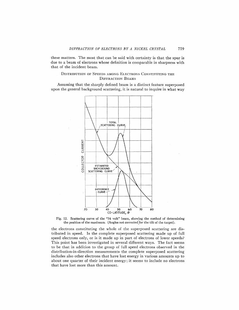
If we regard the spur as a feature superposed on the simple scatteringcurve the position of its maximum is falsified to some extent by the variationwith angle of the background against which it appears. The method ofcorrecting for this effect is indicated by the curves in Fig. 12. The endportions of the observed curve are joined by a curve of the known form ofthe simple relation (see e.g. , Fig. 8), and the difference of these curves isplotted as the graph of the spur. The position of the maximum of thisdifference curve is taken as the true value of 0.
THE WIDTH OF THE SPUR
From the difference curve in Fig. 12 we see that the spur has an apparentangular width of about 25'. What width is to be expected if the spur isdue to a beam of electrons which is as sharply defined as the primary beamed
This latter beam is defined by circular apertures 1 mm in diameter, and ifwe assume that the beam is a cylinder of this diameter, an equally sharpbeam scattered at colatitude 0 would extend over a colatitude arc of (1 && cos 0)mm. The circular opening in the outer box is 1 mm in diameter, and itsdistance from the axis of rotation is 11 mm, so that the least possible valuefor the apparent colatitude width is (1+cos 0)/11 radians, or 5.2(1+cos 0)degrees. For the spur under consideration 0=50', and the calculated widthis 8.5'.
The width in azimuth of the same spur is seen from the lower curve ofFig. 11 to be about 30'. The least value for this width is given by 5.2(2)/sin 0
which for 9=50' amounts to 13.5'. Thus both in colatitude and in azimuththe observed width of the beam is more than double the least possible value.
It is to be expected, of course, that the observed values will be somewhatgreater than those calculated, since it is hardly likely that the primary beamis as sharply defined as has been assumed; it is probably divergent as wellas somewhat nonhomogeneous. There is no way, however, of investigating
DIFFRACTION OIl ELECTRONS BF A NICEZL, CRYSTAL
these matters. The most that can be said with certainty is that the spur isdue to a beam of electrons whose definition is comparable in sharpness withthat of the incident beam.
DISTRIBUTION OF SPEEDS AMONG ELECTRONS CONSTITUTING THEDIFFRACTION BEAMS
Assuming that the sharply defined beam is a distinct feature superposedupon the general background scattering, it is natural to inquire in what way
CU RYE'
ESTIMATEDBACKGROUND
5CATT E R i&G CURVE
DIFFEREN' CURVE
20 30 40 SO Co0
CO-LATITUDE, 870
Fig. 12. Scattering curve of the "54 volt" beam, showing the method of determiningthe position of the maximum. (Angles not corrected for the tilt of the target).
the electrons constituting the whole of the superposed scattering are dis-tributed in speed. Is the complete superposed scattering made up of fullspeed electrons only, or is it made up in part of electrons of lower speeds?This point has been investigated in several different ways. The fact seemsto be that in addition to the group of full speed electrons observed in thedistribution-in-direction measurements the complete superposed scatteringincludes also other electrons that have lost energy in various amounts up toabout one quarter of their incident energy; it seems to include no electronsthat have lost more than this amount.

720 C. DA. VISSON AND 1.. H. GERMER
These characteristics are inferred from the experimental results exhibitedin Fig. 7. The upper curve was obtained with the collector in the center ofa beam in the IGLOO I-azimuth which is strongest at 160 voits. Two othercurves (not shown) were then obtained with the position of the collectorunaltered, but with the bombarding potential changed to 120 volts in onecase, and to 200 volts in the other. The spur does not appear at either ofthese voltages, so that the current-voltage curves for these voltages are for"background" electrons only. These curves are not very different, so thata similar curve for 160 volts may be interpolated with considerable certainty.Curve II of Fig. 7 is this interpolated curve representing the current-voltagerelation for "background" electrons only at 160 volts.
Curve III has been obtained by subtracting II from I, and consequentlyrepresents the current-voltage curve that would be obtained if the "back-ground" scattering could be eliminated. Ke infer from the form of thiscurve that the electrons making up the whole of the superposed scatteringare distributed in energy as described in the previous paragraph. Thedistribution is that which might be expected among the emergent electronsif a homogeneous beam were incident upon an extremely thin plate —a plateonly one or two atoms in thickness.
Although the matters here considered require much more study thanthey have so far received, it is fairly clear that the superposed scattering ismade up of beams of full speed and nearly full speed electrons that approxi-mate the incident beam in sharpness, and that these beams appear only atand near certain critical bombarding potentials.
POSITIONS AND VOLTAGES OF ELECTRON BEAMS
The work of investigating these beams and searching out new ones hasprogressed in several distinct stages. To begin with an exploration wasmade through the principal azimuths in the range 15 to 200 volts. Thirteensets of beams were found, and these were described in our note to "Nature. "The exploration was then extended to 350 volts, and eight additional setswere found. Up to this time the target had been heated last while the tubewas still on the pumps.
After completing the exploration to 350 volts the target was stronglyheated, and allowed to cool again to room temperature. The effect of thistreatment was to increase generally the intensities of the beams withoutaltering either the voltages at which they occurred or their positions. Threesets of beams only were exceptions to this rule, and these were the particularthree sets which in our note in "Nature" we regarded as anomalous; theintensities of these were decreased.
These alterations in intensity resulted, we believe, from removal of gasfrom the surface of the target. In further tests it was found that immediatelyafter bombardment, while the target is still hot, the beams are all weak;that they then increase in intensity as the target cools and that later, pre-sumably as gas collects again on the surface, their intensities decrease. This6na1 decrease in intensity was rather rapid after the erst heat treatments,but after ten or a dozen heatings it was much slower —the intensities of the
DIFFRACTION OE ELECTRONS BY A NICKEL CRYSTAL 72i
beams remaining for hours near their maximum values. This was the be-havior of the normal beams. The three sets of anomalous beams wereprogressively weakened, and finally disappeared.
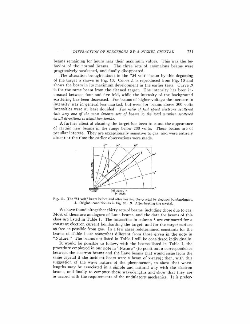
The alteration brought about in the "54 volt" beam by this degassingof the target is shown in Fig. 13. Curve A is reproduced from Fig. 10 andshows the beam in its maximum development in the earlier tests. Curve B.is for the same beam from the cleaned target. The intensity has been in-creased between four and five fold, while the intensity of the backgroundscattering has been decreased. For beams of higher voltage the increase inintensity was in general less marked, but even for beams above 300 voltsintensities were at least doubled. The ratio of full speed electrons scatteredinto any one of the most intense sets of beams to tke total number scatteredin 0,/I directionsis about kzvo-tmths.
A further effect of cleaning the target has been to cause the appearanceof certain new beams in the range below 200 volts. These beams are ofpeculiar interest. They are exceptionally sensitive to gas, and were entirelyabsent at the time the earlier observations were made.
15 50 45
?5
TARGET I111} AZIMUTH
54 VOLTS
Fig. 13. The "54 volt" beam before and after heating the crystal by electron bombardment.A. Original condition as in Fig. 10. B. After heating the crystal.
We have found altogether thirty sets of beams, including those due to gas.Most of these are analogues of Laue beams, and the data for beams of thisclass are listed in Table I. The intensities in column 5 are estimated for aconstant electron current bombarding the target, and for the target surfaceas free as possible from gas. In a few cases redetermined constants for thebeams of Table I are somewhat different from those given in the note in"Nature. " The beams not listed in Table I will be considered individually.
It would be possible to follow, with the beams listed in Table I, theprocedure employed in our note in "Nature" (to point out a correspondencebetween the electron beams and the Laue beams that would issue from thesame crystal if the incident beam were a beam of x-rays); then, with thissuggestion of the wave nature of the phenomenon, to show that wave-lengths may be associated in a simple and natural way with the electronbeams, and finally to compute these wave-lengths and show that they arein accord with the requirements of the undulatory mechanics. It is prefer-

C. DAVISSOE AND I.. H. GERBER
able, however, to start at once with the idea that a stream of electrons ofspeed v is in some way equivalent to a beam of radiation of wave-lengthh/mv, and to show to what extent the observations can be accounted for onthis hypothesis. We assume that this radiation is scattered and absorbedby the atoms of the crystal and that, just as in the case of x-rays, strongdiffraction beams result from coincidence in phase of all of the radiationscattered in some particular direction.
TAar. E ISpace lattice electron beams
Azi.
EquivalentBombarding Wave-lengthPotential V X = (150/ U)'
Colatitude0
BeamIntensity(Arbitrary
Scale)Beam Int.Background
Int.
{»&}
{100}
{tto}
54 volts106174181248258343347
65126160190230292310312370
143170188248
1.67 A1.190.9280.9100.7780.7620.6610.657
1.521.090.9680.8890.8070.7160.6950.6930.636
1.0240.9400.8930.778
50028225544
&203462
4428602046
&20703757
56464334
1.00.42.00.71.04.53.00.07
1.02.00.82.00.47.00.151.50.15
0.20.10.30.45
7.01.41.31.02.61.81.50.3
7.03.85.71.31.22.00.81.20,4
0.90.51.00.6
In considering the conditions under which such beams will occur it will
be convenient to regard the crystal as built up of j111I-planes of atomsparallel to the principal facets, and to picture the radiation scattered bythe crystal as made up of the contributions from all such planes. Thisviewpoint has a distinct advantage, in the present case, over regardingdiffraction beams as built up of contributions regularly rejected from theBragg atom-planes. The amplitude of the radiation proceeding in a givendirection from the crystal is then to be regarded as the sum of the amplitudes(with due regard to phase) of the increments of radiation proceeding in thesame direction from all such j111I-planes of atoms or more—precisely,the fractions of such increments that actually escape-from the crystal.
If we imagine a system of Cartesian coordinates with its origin at thecenter of a surface atom, its positive s-axis extending outward from the facet,and its positive x-axis lying in one of the j110I-azimuths of the crystal,then atom centers occur at the points

DIFFRACTION OF ELECTRONS 8 V A NICKEL CR1 STAL 723
z= (M+F+P)s/2y =3'i'(M —S+P/3) s/2
s = 2' "I'—s/3
where s(=a/2'I') represents the least distance between atoms in a I 111I-plane (the side of the elementary triangle), M and N are any integers, andP is zero or any positive integer.
If a beam of plane waves is incident upon any one of these atom planesalong a line whose direction cosines are l&, m&, n&, it may be shown that theradiation scattered by the individual atoms will be in phase along the direc-tions
t, =1g+ (p+r)X/smr ng+ (p—— r)) /3'—"s
—+ (1 1 2 rs 2)1/2
where ) represents the wave-length of the radiation, and p and r are anyintegers. If the waves meet the layer at normal incidence, as in our experi-ments, then l& =m~ =0, n~ = —1, and
4= (p+r)X/sm, = (p —r)X/3'&'s
n =+(1—lP —F2')'"It may be shown that these are just the directions in which diffraction
beams are to be expected if the plane of atoms is regarded as equivalent toagreat number of line gratings. All of the atoms in the plane may be regardedas arranged on lines parallel to the line joining any two of them, and everysuch set of lines functions as a line grating. Diffraction beams due to eachsuch grating occur in the plane normal to its lines, and satisfy the ordinaryplane grating formula, nX=d sin 0.
The grating constant-d has its greatest value for the three plane gratingsthe lines of which are parallel to the sides of the elementary triangle. Forthese d =d~ ——3'"s/2, and nX = (3"'s/2)sin 0. The beams due to these gratingsoccur symmetrically in the I 111 I and I 100 I-azimuths.
The longest wave-length that can give rise to a diffraction beam is foundby setting n = 1 and sin 0 = 1 in the grating formula in which d has its greatestvalue, i.e. , it is the wave-length 3'"s/2. When waves of this length areincident normally on the plane of atoms first order diffraction beams shouldappear at grazing emergence in the {111Iand I 100I-azimuths —six beamsin all. When the wave-length is decreased these beams should split into twosets of six beams each —one set moving upward toward the incident beam,and the other set moving downward. We are concerned with the upwardmoving set only. When the wave-length has been decreased to 3'"s/4 secondorder beams should appear at grazing, and these'should follow the courseof the first order beams with still further decrease in the wave-length. In themeantime, however, six first order beams from the three gratings of secondlargest spacing (d =d& ——s/2) should have appeared at grazing in the I 110I-azimuths. And as the wave-length is shortened beams should appear in stillother azimuths.

724 C. DAUISSOX AND L. H. GZR3IIZR
These are the diffraction beams to be expected from a single layer ofatoms. In general, when the incident beam is being scattered simultaneouslyfrom a large number of such layers the diffraction beams from the differentlayers must emerge from the crystal out of phase with one another, andthe amplitude of the resultant beam must be much smaller than that whicha single layer should produce.
There are two conditions, however, under which the amplitude of agiven set of beams may be as great as, or greater than, that due to a singlelayer. One of these is the well known case of the Laue beams in which thescattered waves contributed to a particular beam from the consecutive atomlayers are in phase and reenforce one another by constructive interference;the other is the case in which the reduction in intensity of the radiation onpassing through a single layer of atoms —due to scattering and absorption-is so great that no appreciable radiation emerges from the interior of thecrystal to interfere with that scattered by the first layer. The resultantscattering in this case will be approximately that from a single layer ofatoms. This condition will be most closely approached near grazing, sincein this region the paths in the crystal over which radiation from the secondand lower layers must escape are greatly lengthened. The new electronbeams discovered below 200 volts after the crystal was thoroughly degassedappear to be of this latter type. We shall begin our discussion of the datawith an examination of these "plane grating" beams.
The value of the spacing s for nickel is 2.48A, so that iE& ——3'i's/2 = 2.15A,and first order beams should appear at grazing emergence in the I 111j and
I 100 j-azimuths when X(=h/mv) has this value. Rewriting de Broglie'sformula for ) in terms of the kinetic energy U of the electrons expressed inequivalent volts, we have:
X(in Angstrom units) = (150/ V)'i'
From this we calculate that the electron wave-length will have its criticalvalue when V=32.5 volts.
The new beams in the I 100 j and I 111j-azimuths are shown in Figs. 14and 15 in which current to the collector is plotted against bombardingpotential for various colatitude angles. In both azimuths beams appear atgrazing (&=90') at or very near the calculated voltage, and then moveupward toward the incident beam as the voltage is increased. The lowintensities of the beams near grazing are attributed to the general roughnessof the surface and to absorption of the radiation scattered by the first layerby the atoms of the same layer. The final disappearance of these beams at»out 30' above the surface is accounted for by interference between theradiation scattered by the first layer and that escaping from below. Overthis range we expect wave-length and angular position of the beam to berelated through the plane grating formula ) =di sin 0, or voltage and positionthrough the equivalent relation V'" sin 8=(32.5)'i'=5. 70. That the ob-servations are in accord with this requirement is shown by the values cal-culated from Figs. 14 and 15 and recorded in Table II,

DIFFRACTION OIi ELECTRONS BY A NICKEL CRYSTAL
TABLE IIOcclrrence of "plane grating" electron beams.
725
858075706560
32.033,035.036.038.542.5
5.645.665.725.645.635, 65
Azimuth —{100}V Vi~~ sin 0
32.534.035.036.535.0
5.685.755.725.685.37
Azimuth —{111}V Vi~~ sin 0
Azimuth —{110}V Vil~ sin 0
97.5 9.83100.0 9.85103.5 9.83108.0 9.77112.5 9.62
The difference in intensity between the beams shown i 'g .'n Fi s. 14 and 15is due apparently to a real dependence of intensity upon azimuth; the beamsin the three I100I-azimuths are all more intense than the beams in t e
111I-azimuths. We naturally try to account for this difference (w iccould not occur if the scattering were from a single atom layer) by supposingthat although the extinction of the radiation in the metal is sufficiently greatto leave first layer scattering predominant, it is not sufficiently great, even
VOL 525 30 35 40 45 50 55 &0 &5 70 75
BOMBAPDING POTENT(AL
Fig. 14. Collector current vs. bombarding potential showing plane grating beams neargrazing in {100}-azimuth.
near grazing, o sto suppress completely the escape of radiation from lowers is not the1 . The hase difference between first and second layer beams is no e
same in the two azimuths, and as a consequence an intensity i rresults. Whether the observed difference is in the sense to be expecte wibe considered later.
It was expected that second order beams corresponding to the ones justdescribed would be found at grazing for V=4X32.5=130 volts. T eseappear, however, to be entirely missing. We cannot account for this.

726 C. DAVISSOE AND L. H. GBRJI/IZR
On the other hand the anticipated first order beams in the ( 110I -azimuthsresulting from the atomic line gratings of second widest spacing are dulyfound. One of these beams is shown in Fig. 16. The grating constant is s/2,
CYC)I-
0
Z5 30 35 40 45 50 55 &0 &5 70 7$BOMBARDING POTENTIAL
Fig. 15. Collector current vs. bombarding potential showing plane grating beamsnear grazing in {111}-azimuth. "
or 1/3'~' as great as that of the former gratings, so that the beam should
appear at grazing for V=3&(32.5=97.5 volts. The beam appears quiteaccurately at this voltage. It also conforms over the range through which
QC
O
UJ
0V
85 90 95 100 105 1IO 1I5 120 125 t30 l35BOMBARDING POT ANTI AL
Fig. 16. Collector current vs. bombarding potential showing plane grating beams neargrazing in {110}-azimuth.
it can be followed to its appropriate grating formula, ) =d2 sin ter, or V'" sin 0
=(97.5)' '=9.88. Values of V"' sin fi taken from Fig. 16 are given in thelast section of Table II.
These beams, as has been mentioned, are extremely sensitive to thepresence of gas on the surface of the target. They fa11 oR in intensity as the
'o In Fig. 15 the maxima near 50 volts in the curves for 65 and 70 degrees are due to the"54 volt" beam in early stages of its development. The curves in Fig. 15 should be comparedwith those in Fig. 9. The latter are for the target covered with gas; the "plane grating" beamis altogether lacking here, and the "54 volt" beam shows much more weakly than in the curvesin Fig. 15. The rapid rise of the current in all colatit'udes below 30 volts in Fig. 15 is not signi-ficant. It is due to a rapid increase of current in the incident beam which resulted, under theconditions of these measurements, from a focussing action within the electron gun.

DIFFRACTION OF ELECTRONS BF A NICZEL CRFSTAL
gas collects, and disappear when the amount of gas on the surface is in-
su%cient to affect more than slightly the intensity of beams occurring athigher voltages and smaller colatitude angles.
This behavior is consistent with the view already proposed that neargrazing the intensity of scattering is determined almost entirely by theatoms in the topmost layer. When the crystal is clean this is a layer ofregularly arranged nickel atoms which gives rise to the plane grating beams—when gas has collected on the surface it is a layer of gas atoms or moleculeswhich may or may not give rise to diffraction effects of its own, but which,in either case, serves to absorb the radiation from the first layer of nickelato,ms.
We thought that since the radiation in the grazing beams is scatteredmostly by top layer atoms, the electrons in these beams would be morenearly homogeneous (made up more completely of full speed electrons) thanthose in beams at higher voltages and lower colatitude angles —beams moredependent for their intensities upon radiation scattered from atoms in lowerlayers. This appears, however, not to be the case. Current-voltage curvessimilar to those in Fig. 7 have been constructed for the grazing beams, andthese indicate a distribution of speeds quite like that inferred from Curve IIIof Fig. 7.
We have looked also for the first order grazing beams from the planegratings of third largest spacing, but have failed to find them. There shouldbe twelve such beams (six in each of two new azimuths) appearing at 227volts. It is to be expected, of course, that the higher voltage beams of thistype will be weak on account of a less rapid extinction of the equivalent radia-tion in the metal ~ Here, as elsewhere, it appears a dependable procedure toinfer characteristics of the equivalent radiation from known properties ofelectrons; if high speed electrons are less rapidly absorbed than low speedelectrons, we may infer that short wave equivalent radiation is less rapidlyabsorbed than long.
We have looked (also without success) for other beams of this typegrazing the inclined I 111I -facets The ca. lculated positions of most of thesebeams fall so close to intense space lattice beams that it seems unlikely theycould be found, even if present. On the other hand a careful exploration forone particular beam of this sort, the predicted position of which is not tooclose to any space lattice beam, was a complete failure.
SPACE LATTICE BEAMS
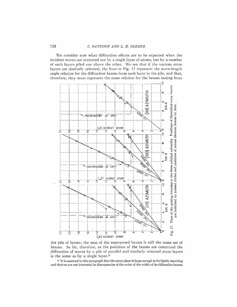
The diffraction pattern for radiation of a given wave-length scatteredby a single atom layer is made up, as has already been described, of theplane grating beams from all of the gratings that can be constructed fromlines of atoms in the layer. The beams occur in planes normal to the linesof these gratings, and satisfy the plane grating formula n) =d sin 0, whered represents the constant of the particular grating considered. This relationis represented graphically by the straight lines in Fig. 17, in which wave-length ) is plotted against sin 0, for beams occurring in the principal azi-muths. For a given value of ) the positions of the beams in the various ordersmay be read off from these lines.
C. DA UISSON AND L. H. GERMEN
We consider now what diffraction effects are to be expected when theincident waves are scattered not by a single layer of atoms, but by a numberof such layers piled one above the other. We see that if the various atomlayers are similarly oriented, the lines in Fig. 17 represent the wave-lengthangle relation for the diffraction beams from each layer in the pile, and that,therefore, they must represent the same relation for the beams issuing from
O
oOv
~NOI JVA53SBO 30 llIRII1
(Jt') kl9N3 I 3RVM
I
NOilVAB3SHO 30 liAi1
0p
( 0) Wl9N3I 3Agi@
~NOllVR53SGO 30 l.IAI1
I—
OC)
o0
2
M
~ ~ 0
0eW
20 cd
0)
00
~ TK
tV
6 cd~ A
N 0CO
cd C"Q
AM e~C4 0CJ
4l m
~ ~ QUJ
CO
bO~~ ~
hpQ oW
Pccd
0C4
(.V) HiSN3i WVV
0
the pile of layers; the sum of the superposed beams is still the same set ofbeams. As far, therefore, as the positions of the beams are concerned thediffraction of waves by a pile of parallel and similarly oriented atom layersis the same as by a single layer. "
" It is assumed in this paragraph that the atom plane is large enough to be highly resolvingand that we are not interested in discrepancies of the order of the width of its diffraction beams.

DIPPRACTION OP ELECTRONS BY A NICEEL CRYSTAL 729
There is, however, a great difference in the intensities of the beams inthe two cases. In the case of scattering from a single layer the intensity ofa given beam would be found ordinarily not to change greatly as the wave-length and position of the beam are varied. In the case of scattering from apile of such layers, however, the intensity of the emergent beam is greatlyaffected by interference among the beams from the individual layers. If agreat number of layers contribute individual beams of about the same in-tensity, as is the case in x-ray scattering, the intensity of the resultant beamwill ordinarily be quite low. When, however, the beams from the individuallayers emerge from the crystal in phase the intensity of the resultant beampasses through a strong maximum. The wave-lengths for which this occursdepend upon the way in which the atom layers are piled up —that is, uponthe separation between successive layers and upon the lateral shift from onelayer to the next. If the wave-length of the radiation within the crystal isnot the same as outside this also will have an effect upon the occurrence ofintensity maxima.
The purpose of setting forth these rather elementary matters at suchgreat length is to bring out clearly that the intense space lattice beams arealways also plane grating beams. If the wave-length and position of sucha beam is represented. by a point in Fig. 17 the point must fall somewhere onone of the plane grating lines.
If the incident beam in the present experiments were a beam of hetero-geneous x-rays an array of Laue diffraction beams would issue from thecrystal. The wave-lengths and positions of all such beams in the threeprincipal azimuths within the range of our observations (8)20', X)0.63A)are indicated in these figures by crossed cycles.
The plane grating lines for azimuths I 111} and I 100} are, of course, thesame, but the occurrence of Laue beams in these azimuths is different.The wave-lengths that give rise to diffraction beams in the I 111}-azimuthare not the same, except in such orders as are exactly divisible by three, asthose that give rise to beams in the I 100 }-azimuth. And the same statement,mntatis mntarsdis, may be made, of course, in regard to the angles at whichbeams occur in the two azimuths. When the wave-lengths or angles of thebeams of any order, not exactly divisible by three, are ordered according tomagnitude the members belonging to one azimuth occur alternately withthose belonging to the other. These characteristics result from the fact thatto superpose the atoms of one layer upon those of an adjacent layer involvesa displacement normal to the grating lines equal to (2n+2/3) times thegrating space —n representing any integer. If the odd fraction were one-halfor zero, as in the I 110}-azimuth, these differences would not occur.
In this same figure we have indicated by dots the wave-lengths andpositions of all sets of electron beams listed in Table I. The first thing tobe noted about the dots is that they fall generally along the basic planegrating lines, and to this extent satisfy the fundamental requirement that aspace grating beam shall be first of all a plane grating beam. It will be notedalso that they occur along these lines at about the same intervals as the

730 C. DA UISSON AND L. H. GERBER
crossed circles, and further that in the {111} and {100 }-azimuths theyexhibit the alternate occurrence characteristic of the crossed circles.
While the dots representing the sets of electron beams fall generallyalong the plane grating lines, one cannot fail to note that they actually falloR these lines —and systematically; they are above or to the left of the linesas one cares to view them. At the time of writing our note to "Nature" webelieved that these departures could be accounted for by imperfections inthe geometry of the apparatus. At present, with more data at our disposal,we are less certain that this is true. The fault of this explanation is that if thedisplacements of the dots from the lines result from imperfect alignment,angular displacement should be a function of angular position, and thiscondition seems not very well satisfied. The results of these investigationsdo not, however, rule out mechanical imperfection as the principal causeof these displacements, and for the present we shall assume it to be the onlycause. We shall assume, that is, that the wave-lengths or voltages of thebeams are correct but that the dots should be shifted to the right onto thelines. These shifts correspond to corrections in angle ranging from zero toabout four degrees. We hope to remove the uncertainty here involved bymeasurements with a new tube now being constructed.
As the dots occur at about the same intervals along the lines as the crossedcircles it is possible to associate each dot with a particular crossed circle—each set of electron beams, that is, with a particular set of x-ray beams,and consequently with a particular set of Bragg atom planes in the crystal.The associations which seem most natural are indicated by dotted lines inthe figure. In the {110}-azimuth the association is imperfect as it appearsthat both the 0.893A and the 0.940A electron beams should be associatedwith the same x-ray beam. We have associated the stronger of these withthe x-ray beam, and left the extremely weak electron beam at 0.940A withoutan apparent x-ray analogue. Also there is apparently a third order electronbeam missing in the {111}-azimuth. We should expect this beam to beextremely weak.
We consider next the difference in position between each crossed circleand the location upon the line to which the associated dot is shifted asexplained above. The positions of the lines are determined by the arrange-ment of atoms in a single plane and the scale factor of the structure, while thepositions of the crossed circles are determined by the separation betweensuccessive planes and the lateral shift from one plane to the next. If theseparation were decreased the crossed circles would all be moved downwardalong their lines; if it were increased they would be moved upward. Merelyas a matter of description, therefore, we may say that a given dot whenshifted occupies the position that its associated crossed circle would occupyif the separations between atom planes were decreased by a certain factor.This factor P may be calculated from the formula
tan (8'/2)p=
tan (0,/2)

DIFFRACTION OF ELECTRONS BY' A NICEEL CRYSTAL 73i
Here 0 represents the colatitude angle of the Laue x-ray beam and 0' thatof the associated electron beam after having been corrected to make thebeam satisfy the grating formula exactly.
This factor P is found to be neither constant nor very regular in itsbehavior, but to increase generally with the speed of the electrons. Therelation between the factor P and the bombarding potential is representedby the lower set of points in Fig. i8. There is a vague suggestion here thatP approaches unity as a limiting value. If this is actually the case, it means,of course, that at sufficiently high voltages (short wave-lengths) there is nodifference between the occurrence of x-ray and electron diffraction beams.This approach of the electron beam to the associated x-ray beam with
).00
m .g5
h .90
4Ox .85
m .80C3
.75
u .70
CLCA .G5
/lQ&
t I
QI
o/ I j
'l ig//
lI
~ (1tt —AZIMUTH
~x( /
/ o (100 - AZIMUTH
/~ (l10}- AZIMUTH
/I i
/
/ I
rX
Ii
VOLTS
0 OO 'I20 f&0 200 240 280 320 3' 400BOMBARDING POTENTfAL
Fig. 18. Lower set of points —Spacing factor P vs. bombarding potential; Upper set ofpoints —Index of Refraction p, vs. bombarding potential.
increasing voltage is shown very clearly by the series of three dots (Fig. 17)representing the first three orders of the beam whose first order is the 54 voltbeam in the I111}-azimuth (X=1.67A). The first, second and third orderbeams occur at 0=50', 55' and 62' respectively, while the correspondingx-ray beam occurs in each case at 8=70' (sin 8=0.94).
It has been suggested by Eclrart" that this P factor may be interpretedas an index of refraction of the nickel crystal for the equivalent radiation.If the index of refraction of a crystal for radiation of a given wave-length isother than unity, diffraction will indeed occur as if the spacing betweencrystal planes were altered by a certain factor. This factor is not, however,
'~ Eckart, Proc. Nat. Acad. Sci. 13, 460 (1927).
732 C. DA UISSOX AND I.. II. GZRMZR
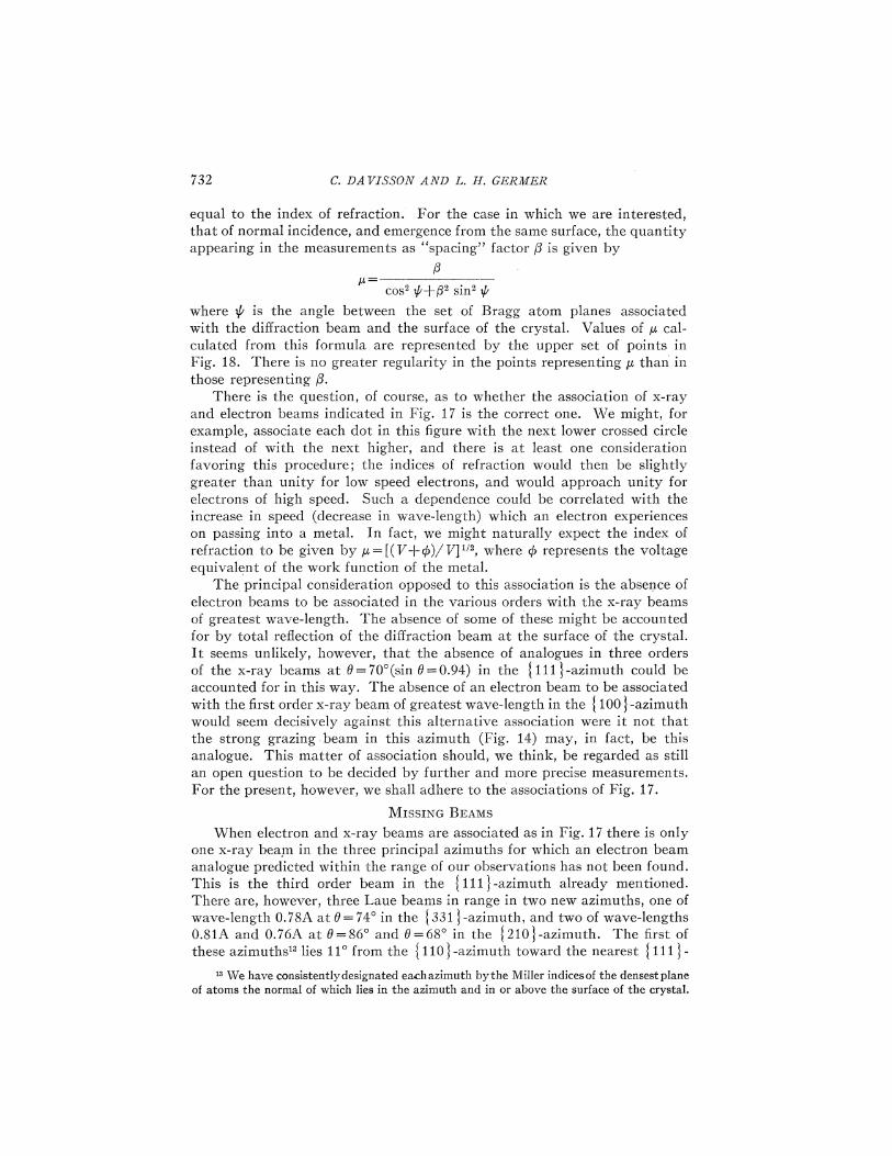
equal to the index of refraction. For the case in which we are interested,that of normal incidence, and emergence from the same surface, the quantityappearing in the measurements as "spacing" factor J3 is given by
pp=cos' P+P' sin' P
where P is the angle between the set of Bragg atom planes associatedwith the diffraction beam and the surface of the crystal. Values of p cal-culated from this formula are represented by the upper set of points inFig. 18. There is no greater regularity in the points representing p than inthose representing P.
There is the question, of course, as to whether the association of x-rayand electron beams indicated in Fig. 17 is the correct one. We might, forexample, associate each dot in this 6gure with the next lower crossed circleinstead of with the next higher, and there is at least one considerationfavoring this procedure; the indices of refraction would then be slightlygreater than unity for low speed electrons, and would approach unity forelectrons of high speed. Such a dependence could be correlated with theincrease in speed (decrease in wave-length) which an electron experienceson passing into a metal. In fact, we might naturally expect the index ofrefraction to be given by p =[(V+/)/V]'", where $ represents the voltageequivalent of the work. function of the metal.
The principal consideration opposed to this association is the absence ofelectron beams to be associated in the various orders with the x-ray beamsof greatest wave-length. The absence of some of these might be accountedfor by total refiection of the diffraction beam at the surface of the crystal.It seems unlikely, however, that the absence of analogues in three ordersof the x-ray beams at 0=70'(sin 0=0.94) in the j111}-azimuth could beaccounted for in this way. The absence of an electron beam to be associatedwith the first order x-ray beam of greatest wave-length in the j 100 }-azimuthwould seem decisively against this alternative association were it not thatthe strong grazing. beam in this azimuth (Fig. 14) may, in fact, be thisanalogue. This matter of association should, we think, be regarded as stillan open question to be decided by further and more precise measurements.For the present, however, we shall adhere to the associations of Fig. 17.
MISSING BEAMS
When electron and x-ray beams are associated as in Fig. 17 there is onlyone x-ray beam in the three principal azimuths for which an electron beamanalogue predicted within the range of our observations has not been found.This is the third order beam in the j111}-azimuth already mentioned.There are, however, three Laue beams in range in two new azimuths, one ofwave-length 0.78A at 0 = 74' in the j 331 }-azimuth, and two of wave-lengths0.81A and 0.76A at 9=86' and 0=68' in the j210}-azimuth. The first ofthese azimuths" lies 11' from the j 110}-azimuth toward the nearest j 111}-
"We have consistentlydesignated each azimuth by the Miller indices of the densest planeof atoms the normal of which lies in the azimuth and in or above the surface of the crystal.

DIFFRACTION OF ELECTRONS BY A NICKEL CRYSTAL 733
azimuth, and the second lies an equal interval on the opposite side of the
I 110}-azimuth. A thorough but fruitless search has been made for the elec-tron beam companions of these three Laue beams.
The total number of x-ray beams for which electron beam companionsare expected within the range of our observations is twenty-four, and fortwenty of these the electron beam companions have been found. The foursets of missing electron beams are all beams whose intensities we shouldexpect to be low. They are all short wave-length beams lying not far abovethe plane of the target.
THIRD ORDER BEAMS IN THE I 111} AND I 100}-AZIMUTHS
The differences which have been noted between the occurrence of x-raydiffraction beams in the I 111}and I100}-azimuths do not extend, as hasbeen mentioned, to orders that are exactly divisible by three; the wave-lengths and positions computed for the third order x-ray beams in one ofthese azimuths are identical with those computed for the third order beamsin the other. Differences in intensity between corresponding beams mightpossibly result from a dependence of the scattering power of a single atomupon crystal direction, but, so far as we are aware, differences of this sortare not found in x-ray data.
It seemed reasonable to expect, therefore, that the third order electronbeams in the I 111}-azimuth would be found identical in voltage, position,and possibly also in intensity, with beams of the same order in the I 100}-azimuth. This agreement, however, is not observed. Two pairs of beamsare available for observation, and the beams of each pair have constantsthat are different. The data are given below in Table III.
TABLE IIIThird order electron beams.
{SST}{551j 60' 347
{111}-azimuthx-ray companion 0 Int.
0.000.07
Int.
310 0.15370 0.15
{100}-azimuthx-ray companion 0 U
{211} 20'{822 57
RESOLVING POWER OF THE CRYSTAL
It has been remarked (Fig. 10) that the space lattice beams are notsharply de6ned in voltage. The "54 volt" beam, for example, appears whenthe bombarding potential is about 40 volts and is still prominent in thecurve for V=64 volts. In terms of equivalent wave-lengths the beam hasappreciable intensity over a range AX which is about one quarter as greatas the equivalent wave-length of the beam at its maximum intensity. Thecorresponding ratios for beams of higher voltage are generally less, but evenfor beams for which U is greater than 300 volts values of AX/X are foundas great as 0.07. |jtIte naturally conclude that as an optical instrument thecrystal has low resolving power.

734 C. DAVISSOE AND L. H. GER3IIER
It might appear that this low resolving power is readily accounted forby the fewness of the atom planes contributing effectually to the scattering.In accounting for the "plane grating" beams we have already had occasionto assume that the extinction of the equivalent radiation in the metal isextremely rapid, and it may appear that no further assumption will berequired to account for the low resolving power observed in the space latticebeams. It must be realized, however, that the resolving power of a spacelattice is dependent not only upon the number of its atom planes, but alsoupon the number of grating lines in each plane, and that to ascribe the lowresolving powers in the present case solely to the slight penetration of theradiation into the metal is to assume that the number of grating lines ineach of the atom planes making up the lattice is relatively great —greatcompared with the number of effective planes. If the width of the latticewere the same as the width of the bombarded area this assumption would,of course, be amply justified. There are, however, at least two reasons forregarding the diffracting system not as a single lattice, but as a collection ofvery many extremely small lattices, similarly oriented but otherwise un-related. A large part of the radiation proceeds, it would seem, from latticesnot more than five or ten atom lines in width.
The first reason for ascribing this small width to the unit lattice is thaton no other assumption have we been able to account for the great width ofsuch peaks as those shown in Figs. 9, 14, 15 and 16. The width of these peaksis due in part, of course, to the width of the diffraction beam and to that ofthe collector opening, but these geometrical considerations are quite in-sufficient for the purpose. The curves referred to seem to show clearly thatthe resolving power of the topmost atom layer is quite low, and that con-sequently most of the radiation from this layer comes from independentgratings containing only a few atom lines each.
The second reason has to do with the relation between the voltage andthe angular position of a space lattice beam in the various stages of itsdevelopment. We have seen (Table II) that as a "plane grating" beam risesfrom the surface of the crystal the product U'~' sin 8 remains constant.At one time we expected that the same relation would be found to obtainwithin a space lattice beam —that as the voltage was increased the beamwould in all cases move upward to keep V'" sin 0 constant. This relationdoes in fact hold reasonably well for the "54 volt" beam. It holds less well,however, for the "65 volt" beam shown in Fig. 10, and fails entirely formost beams occurring at higher voltage. In many cases the total angulardisplacement during the growth and decay of the beam is not more thanone-tenth that required by the plane grating formula. It may be shown,however, that the plane grating formula (V"2 sin 8 =constant) will describethe motion of the beam if the lattice is su6ciently wide, but that it will failto do so otherwise. If the number of lines in the plane grating is not greatcompared with the number of atom planes, the plane grating relation willnot obtain (except at the maximum of a beam —when the scattering fromsuccessive layers is exactly in phase) and departures from it will be in thedirection of those that we have observed.

DIFFRACTION OF ELECTRONS BF A NICKEL CRFSTAL 735
There are thus these two reasons for thinking that most of the scatteredradiation proceeds from lattices not more than five or ten grating lines inwidth, and that the low resolving power of the plane gratings that make upthe representative lattice is partly responsible for the low resolving powerapparent in the space lattice beams. " It seems probable that the independentlattices are to be identified with the individual facets of the principal set-those parallel to the general plane of the target.
If the resolving power of the crystal were determined solely by the rateof extinction of the radiation in the metal, it would be possible to make useof the intensity-voltage relation within a given beam to calculate a coeKcientof extinction of the metal for radiation of the wave-length of the beam, assuggested by Eckart (loc. cit.), or to estimate the number of atom planeseffective in the scattering, as suggested by Patterson. " It may even bepossible under the actual conditions of the scattering to evaluate theseconstants by making use also of the observed relation between the angularposition of the beam and voltage. But the data which we have at presentseem to us too inaccurate to make such calculations worth while. We hopeto obtain data su%ciently precise for this purpose in the near future.
We have, however, calculated a rate of extinction from the data obtainedfor the "54 volt" beam with the surface of the target free from gas (not fromthe data of Fig. 10). As has already been mentioned, the product Pi' sin 0is very nearly constant in this beam, which means that its intensity-voltagerelation is determined almost entirely by the rate of extinction. As theresult of this calculation we have obtained the value 0.4 for the fraction bywhich the intensity of a beam of 54 volt equivalent radiation is reduced whensuch a beam passes normally through a, single I 111}-layer of nickel atoms.In terms of electrons this means presumably that when a 54 volt electronis incident normally upon such a layer the probability of its passing throughwithout appreciable deHection or loss of energy is 0.6."
INTENSITIES OF PLANE GRATING BEAMS
We return now to a further consideration of the intensity differencebetween the first order "plane grating" beams in the I 100} and I111}-azimuths (Figs. 14 and 15). If these were truly plane grating beams nodifference of intensity should be observed. We have already pointed out,however, that it is only in the limit, as 8 approaches s/2, that these beamsare due to scattering from a single atom layer. They are actually spacelattice beams, and their occurrence and behavior are described by the samemathematical formulas that describe the Laue type of beam. The intensityof a "plane grating" beam depends upon the efficiency with which a single
4 It was shown in an earlier section that the apparent angular width of a space latticebeam (voltage constant) has more than double its least possible value as calculated from thedimensions of the apparatus. It seems probable from the present considerations that a con-siderable part of this additional width is to be ascribed to the low resolving power of the crystal.
"A. L. Patterson, Nature 120, 46, (1927)."This question of resolving power has been considered recently by F. Zwicky (Proc. Nat.Acad. Sci. 13, 519 (1927)) in terms of the wave mechanics as formulated by Schroedinger andBorn.
736 C. DAVISSON AND L. H. ARMER
atom scatters the radiation incident upon it, and upon the rate of extinctionof the radiation in the crystal. Such beams are not found when x-rays arescattered by a crystal because in this case both of these quantities are small.
The problem of finding which of the two beams under considerationshould be the stronger resolves itself into finding in which azimuth the firstorder diffraction beams from successive atom layers are more nearly in
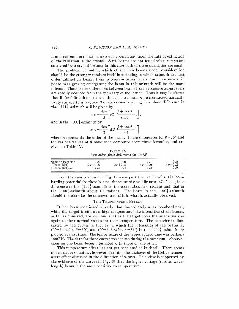
phase near grazing emergence; the beam in this azimuth will be the moreintense. These phase differences between beams from successive atom layersare readily deduced from the geometry of the lattice. Thus it may be shownthat if the diffraction occurs as though the crystal were contracted normallyto its surface to a fraction P of its normal spacing, this phase difference in
the {111j-azimuth will be given by4~m 1+ cos0
nggg = P2'~2 —+13 sin 0
and in the {100j-azimuth by4~m 1+ cos 8
Q.zoo = p2~t2 . ——13 sin 0
where n represents the order of the beam. Phase differences for 0= 75' andfor various values of P have been computed from these formulas, and aregiven in Table IV.
TAa~E IVFirst order phase digererIces for 0=75'
Spacing Factor P(Phase Diff)»&(Phase Biff)100
0.527f.+1.8—0.3
0.62~+2.5
0.4
0.7471- —3 .0
1.20.8
471.—2.22.0
From the results shown in Fig. 18 we expect that at 35 volts, the bom-barding potential for these beams, the value of P will lie near 0.7. The phasedifference in the {111j-azimuth is, therefore, about 3.0 radians and that in
the {100}-azimuth about 1.2 radians. The beam in the {100}-azimuthshould therefore be the stronger, and this is what is actually observed.
THE TEMPERATURE EFFECT
It has been mentioned already that immediately after bombardment,while the target is still at a high temperature, the intensities of all beams,as far as observed, are low, and that as the target cools the intensities riseagain to their normal values for room temperature. The behavior is illus-trated by the curves in Fig. 19 in which the intensities of the beams at(U= 54 volts, 0=50') and (U=343 volts, 0=34') in the {111j-azimuth areplotted against time. The temperature of the target at zero time was perhaps1000'K. The data for these curves were taken during the same run —observa-tions on one beam being alternated with those on the other.
This temperature effect has not yet been studied in detail. There seemsno reason for doubting, however, that it is the analogue of the Debye temper-ature effect observed in the diffraction of x-rays. This view is supported bythe evidence of the curves in Fig. 19 that the higher voltage (shorter wave-length) beam is the more sensitive to temperature.

DIFFRACTION OF ELECTRONS BY A. NICE'EL CRYSTAL
BEAMS DUE TO ADSORBED GAS
737
The "plane grating" beams and space lattice beams for which data havebeen given in previous sections are the only beams observed when the targetis, as we believe, free from gas. When the target is not free from gas stillother beams appear. Three sets of these have already been mentioned as theones referred to in our note to "Nature" as anomalous; one set occurs ineach of the three principal azimuths, and all attain their maximum intensityat or close to 0=58', V=110 volts. These beams appear to depend fortheir existence upon the presence of a considerable amount of gas on thesurface of the target; they were most intense before the first bombardment ofthe target, and were not found when the amount of adsorbed gas was known
543 VOLT BEAM ~ ~
5
oc 4
3
02
p 0
54 VOLT BEAM
Qo~~)
00 10 ZO
I
30 4Q 50 Cp0 TO
MlNUTE5 AFTER BOMBARDMENT
80
Fig. 19. Intensities of 54 volt beam and 343 volt beam vs. time, immediately after heatingthe target crystal.
to be slight. It should be possible to infer from the characteristics of thesebeams something about the arrangement of atoms to which they are due.It is clear, for example, that the arrangement is determined in part by theunderlying nickel, since the beams occur in the principal azimuths of thenickel structure. We have been unable, however, to carry the deductionbeyond this point.
With certain other beams due to gas we have been more successful.These constitute a family attaining greatest intensity when the quantityof adsorbed gas has a certain critical value. Various members of this familywere observed 6rst as beams of unusual behavior that appeared in placesin which no beams were expected, and disappeared or changed in intensityfor no apparent reason. Thus a beam was occasionally found in the I 110}-azimuth at 0=75', V=25 volts. No such beam could result from scattering
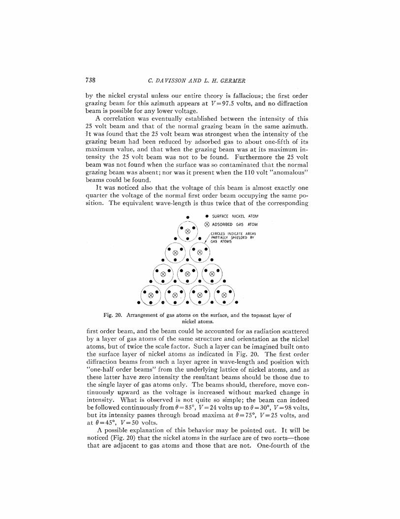
C. DAVISSON AND I. H; GEMS'
by the nickel crystal unless our entire theory is fallacious; the first ordergrazing beam for this azimuth appears at V=97.5 volts, and no diffractionbeam is possible for any lower voltage.
A correlation was eventually established between the intensity of this25 volt beam and that of the normal grazing beam in the same azimuth.It was found that the 25 volt beam was strongest when the intensity of thegrazing beam had been reduced by adsorbed gas to about one-fifth of itsmaximum value, and that when the grazing beam was at its maximum in-tensity the 25 volt beam was not to be found. Furthermore the 25 voltbeam was not found when the surface was so contaminated that the normalgrazing beam was absent; nor was it present when the j.10 volt "anomalous"beams could be found.
It was noticed also that the voltage of this beam is almost exactly onequarter the voltage of the normal first order beam occupying the same po-sition. The equivalent wave-length is thus twice that of the corresponding
0 5UPFACE NICKEL ATOM
GA5 ATOM
CATE AREASfIIELDED B~
Fig. 20. Arrangement of gas atoms on the surface, and the topmost layer ofnickel atoms.
first order beam, and the beam could be accounted for as radiation scatteredby a layer of gas atoms of the same structure and orientation as the nickelatoms, but of twice the scale factor. Such a layer can be imagined built ontothe surface layer of nickel atoms as indicated in Fig. 20. The first orderdiffraction beams from such a layer agree in wave-length and position with"one-half order beams" from the underlying lattice of nickel atoms, and asthese latter have zero intensity the resultant beams should be those due tothe single layer of gas atoms only. The beams should, therefore, move con-tinuously upward as the voltage is increased without marked change inintensity. What is observed is not quite so simple; the beam can indeedbe followed continuously from 0=85', V=24 volts up to 0=30', V=98 volts,but its intensity passes through broad maxima at 0=75', V=25 volts, andat 0=45, V=50 volts.
A possible explanation of this behavior may be pointed out. It will benoticed (Fig. 20) that the nickel atoms in the surface are of two sorts —thosethat are adjacent to gas atoms and those that are not. One-fourth of the
DIFFRACTION OF ELECTRONS J3F A NICKEL CRFSTAL 739
nickel atoms are of this latter class, and they together form a layer of thesame structure, orientation and scale factor as the gas atoms. If the twoclasses of nickel atoms scatter radiation in different amounts —if, for example,the gas atoms shield the adjacent nickel atoms more effectually than thenon-adjacent —then, of course, the layer of nickel atoms as a whole will giverise to a differential diffraction beam capable of interference with that dueto the gas layer, and broad maxima of the sort observed will result.
It was anticipated, of course, that beams of the same nature would befound in the I 111I and I 100I-azimuths. These should appear at grazingat 7= 32.5/4 = 8.1 volts and should move upward with increasing voltage—reaching 0 = 20 at V= 70 volts. Observations cannot be made for bombard-ing potentials as low as 8 volts. The beams have been picked up, however,in both azimuths at 0 = 60', V= 12 volts, and have been followed upwardto 0=25', V=45 volts. Broad maxima occur at 0=35', V=25 volts, andat 8=55', V=13 volts in the I100I-azimuth; and in the I111I-azimuth abroad maximum occurs at 0=55', V=14 volts, and another is indicated inthe neighborhood of 0=25', V=45 volts. It should be possible from thesedata to calculate the separation, or at any rate the apparent separation, ofthe gas layer from the crystal —but this has not yet been attempted.
We have further observed that these beams cannot be made to appearwhen the temperature of the target is somewhat above that of the room;glowing the filament back of the target raises the temperature of the targetsufficiently to eliminate them entirely, although under these conditions gasstill collects on the target, and reduces the intensities of the grazing beams.The explanation of this behavior may be that the melting point of the twodimensional gas crystal is not far above room temperature. We have notyet observed whether the beams disappear sharply at a critical temperature.
FURTHER EXPERIMENTS WITH GAS
In a final series of experiments the effect was studied of introducing largeamounts of gas into the tube. The liquid air was removed from the charcoaltube, and the behaviors of the "54 volt" beam and of one of the anomalous"110 volt" beams were observed as the charcoal was heated. The latterof these beams had not been observed for several weeks —not since its dis-appearance during the first heatings of the target.
The initial effect of increasing the gas pressure was to decrease the in-tensity of the "54 volt" beam. Its intensity was, however, greater thanthat represented by curve A in Fig. 13 until the charcoal temperaturereached 350'C. At about this time the anomalous beam made its appearance.Maintaining the charcoal at 350'C the 54 volt beam decreased rapidly inintensity, vanishing entirely within a few minutes. In the meantime theintensity of the anomalous beam increased, reaching a maximum at aboutthe time the 54 volt beam vanished, after which it too decreased and finallyvanished. The gas pressure within the apparatus, as shown by ionizationmeasurements, was perhaps 10 4 mm Hg at this time.
Heating was discontinued and liquid air was replaced on the charcoal.This caused the pressure to return to a very low value, but it did not bring

C. DAVISSOE AND I.. II. GERBER
back either the 54 volt beam or the anomalous beam. Heating the target byelectron bombardment did, however, bring back the 54 volt beam to aboutits maximum intensity (curve 8, Fig. 13). At this time the anomalous beamwas found to be absent. The 54 volt beam did not maintain its initial in-tensity but decreased rapidly, indicating that the vacuum condition of thetube as a whole had been greatly impaired by heating the charcoal. Nofurther tests were made.
SUMMARY QF ELEcTRQN BEAMs
Thirty sets of electron beams in all have been observed for bombardingpotentials below 370 volts. Eleven of these occur in the I 111}-azimuth,twelve in the I 100}-azimuth and seven in the t 110}-azimuth.
Twenty of the sets have been associated with twenty sets of Laue beamsthat would issue from the same crystal if the incident beam were x-rays.
Three sets are accounted for as "plane grating" beams which result froma preponderance of top layer scattering at angles near grazing emergence.
Six sets are attributed to scattering by adsorbed gas on the surface ofthe crystal, and the structure of the gas film giving rise to three of thesebeams has been inferred.
Some explanation has thus been given for twenty-nine of the thirty setsof beams. The remaining set occurs at 0=46' in the I110}-azimuth forU=170 volts, and is quite weak.
The explanations used in accounting for the observed beams require theoccurrence of still other beams that have not been observed. . The total ofthese missing beams is at least eight; four space lattice beams (one thirdorder beam in the I 111}-azimuth, one first order beam in the I 210 }-azimuthand two first order beams in the I 331 }-azimuth); and four "plane grating"beams (first order I210} and I331}-azimuths, and second order I111}and
I 100 }-azimuths).Discrepancies have also been noted between the characteristics of the
third order space lattice beams in the I 111}-azimuth and those of theircompanions in the I 100}-azimuth.
The possibility of carrying through these investigations to their presentstage has depended very largely upon the cooperation we have receivedfrom a number of our colleagues here in the laboratory. We are particularlyindebted to Drs. H. D. Arnold and W. Wilson for the encouragement theyhave given us and for the benefit of their criticisms. We have had thebenefit also, in technical matters, of discussions with Drs. L. W. McKeehan,K. K. Darrow and R. M. Bozorth.
We are indebted to Mr. H. T. Reeve for producing for us single nickelcrystals of appropriate size—to Mr. C. J. Calbick for assistance in makingthe observations and for contributing not a little to their interpretation-and to Mr. G. E. Reitter for the great care with which he constructed thespecial apparatus and for his many contributions to its design.
BELL TELEPHONE LABORATORIES, INC. )
NEw YORK, N. Y.August 27, 1927.