Embed Size (px)
Citation preview

9.3diffraction and interference of Water WavesHaveyouevernoticedhowpeoplerelaxingattheseashorespendsomuchoftheirtimewatchingtheoceanwavesmovingoverthewater,astheybreakrepeatedlyandrollontotheshore?Waterwavesbehavesimilarlytootherkindsofwavesinmanyways.Figure 1 illustratesonecharacteristicbehaviourofwaveswhenapartof thewave enters through a narrow opening. The section of the wave that gets throughactsasasourceofnewwavesthatspreadoutontheothersideoftheopening,andthewavesfromthetwosourcescombineinspecificways.Youwilllearnaboutthesecharacteristicbehavioursofwavesinthissection.
Figure 1 When part of a wave enters a narrow opening, such as this bay, new waves are created and the two waves combine in predictable ways.
diffractionIf you observe straight wave fronts in a ripple tank, you can see that they travelina straight line if thewaterdepth isconstantandnoobstaclesare in theway. If,however,thewavespassbyanedgeofanobstacleorthroughasmallopening,thewavesspreadout.Diffraction isthebendingofawaveasthewavepassesthroughanopeningorbyanobstacle.Theamountofdiffractiondependsonthewavelengthofthewavesandthesizeoftheopening.InFigure 2(a),anobstaclediffractsshorterwave-lengthsslightly.InFigure 2(b),thesameobstaclediffractslongerwavelengthsmore.
short wavelengths
(a)
long wavelengths
(b)
Figure 2 When waves travel by an edge, (a) shorter wavelengths diffract less than (b) longer wavelengths.
diffraction the bending and spreading of a wave when it passes through an opening; dependent on the size of the opening and the wavelength of the wave
9.3 Diffraction and Interference of Water Waves 459NEL
8160_CH09_p434-469.indd 459 4/30/12 9:47 AM

Althoughdiffractionalsooccursforsoundandlightwaves,wewillstudythephenom-enonfirstforwaterwavesbecausetheirlongwavelengthallowsforeasierobservationoftheeffectsofdiffraction.
InFigure 3(a),youcanseeawaveencounteringaslitwithacertainwidth,w.InFigure 3(b) and Figure 3(c),thewidthoftheopeningisthesamebutthewavelengthof the incidentwaveshaschanged.Noticehowtheamountofdiffractionchanges.Th erefore, as the wavelength increases but the width of the slit does not, the dif-fraction also increases. In Figure 3(a), the wavelength is approximately one-thirdofw.Noticethatonlythepartofthewavefrontthatpassesthroughtheslitcreatestheseriesofcircularwave frontson theother side. InFigure3(b), thewavelengthisabouthalfofw, whichmeansthatsignificantlymorediffractionoccurs,butareasto the edge exist where no waves are diffracted. In Figure 3(c), the wavelength isapproximatelytwo-thirdsofw,andthesectionsofthewavefrontthatpassthroughtheslitarealmostallconvertedtocircularwavefronts.
Whathappensifyouchangethewidthoftheslit butkeepthewavelengthfixed?AsFigure 4(a)andFigure 4(b)show,asthesizeoftheslitdecreases,theamountofdif-fractionincreases.Ifwavesaretoundergomorenoticeablediffraction,thewavelengthmustbecomparabletoorgreaterthantheslitwidth(λ$w).Forsmallwavelengths(suchasthoseofvisible light),youneedtohavenarrowslitstoobservediffraction.Figure 4(c) shows what happens to the diffraction pattern when the wavelengthdecreasesbutthesizeoftheslitdoesnotchange.
Figure 3 As the wavelength increases, the amount of diffraction increases.
(a) (b) (c)
incident waves nearlystraight-linepropagation
large opening(a)
incident waves
small opening(b)
incident waves
shorter wavelength,no change in opening(c)
Figure 4 (a) and (b) As the size of the slit (aperture) decreases, diffraction increases. (c) With a shorter wavelength and no change in the size of the opening, there is less diffraction.
Th erelationshipbetweenwavelength,widthoftheslit,andextentofdiffractionisperhapsfamiliarforsoundwaves.Youcanhearsoundthroughanopendoor,evenifyoucannotseewhatismakingthesound.Th eprimaryreasonthatsoundwavesdif-fractaroundthecornerofthedooristhattheyhavelongwavelengthscomparedtothewidthofthedoorway.Lowfrequencies(thelongerwavelengthsofthesound)diffractmorethanhighfrequencies(theshorterwavelengthsofthesound).Soifasoundsystemisintheroomnextdoor,youaremorelikelytohearthelowerfrequencies(thebass).InthefollowingTutorial,youwilllearnhowtosolveproblemsrelatingtodiffraction.
Properties of Water Waves (page 487)You have learned how observing water waves helps in understanding the properties of waves in general. This investigation will give you an opportunity to test conditions for diffraction to occur.
Investigation 9.3.1
460 Chapter 9 • Waves and Light NEL
8160_CH09_p434-469.indd 460 4/30/12 9:47 AM

Tutorial 1 Diffraction
The following Sample Problem provides an example and sample calculations for the concepts of diffraction.
Sample Problem 1: Diffraction through a SlitDetermine and explain the difference between the diffractions observed in Figure 5(a) and Figure 5(b).
Figure 5
wa � 2 cm
� � 0.5 cm
(a)wb � 0.5 cm
� � 0.5 cm
(b)
Given: l 5 0.5 cm; wa 5 2 cm; wb 5 0.5 cm
Required: diffraction analysis
Analysis: l
w$ 1
Solution:For Figure 5(a),
l
wa5
0.5 cm2 c m
5 0.25
l
wa, 1
For Figure 5(b),
l
wb5
0.5 cm0.5 cm
l
wb5 1
Statement: Since the ratio in Figure 5(a) is less than 1, little diffraction occurs. Since the ratio in Figure 5(b) is 1, more noticeable diffraction occurs.
Practice 1. Determine whether diffraction will be noticeable when water waves of wavelength
1.0 m pass through a 0.5 m opening between two rocks. T/I [ans: yes]
2. A laser shines red light with a wavelength of 630 nm onto an adjustable slit. Determine the maximum slit width that will cause significant diffraction of the light. T/I [ans: 6.3 * 10-7 m]
9.3 Diffraction and Interference of Water Waves 461NEL
8160_CH09_p434-469.indd 461 4/30/12 9:47 AM

constructive interference the phenomenon that occurs when two interfering waves have displacement in the same direction where they superimpose
speaker 1
listener
speaker 2
L2
�
L1
(a)
Waves are in phase.
constructive interference
�
�
�
(b)
Waves are 180° out of phase.
destructive interference
�
�
2�
(c)
Figure 6 (a) If L1 and L2 are the same, the waves arrive at the listener in phase. (b) Waves interfere
constructively if they arrive in phase. (c) If L1 and L2 differ by, say, l
2, the waves arrive 1808 out of
phase, and they interfere destructively.
Fortwowavesthatdifferinphasebyl
2,showninFigure6(c),thecrestofonewave
coincideswiththetroughoftheotherwave.Thiscorrespondstoaphasedifferenceof1808.Thetwowavescombineandproducearesultingwavewithanamplitudethatissmallerthantheamplitudeofeitherofthetwoindividualwaves.Thisphenomenoniscalleddestructive interference.
Thefollowingconditionsmustbemetforinterferencetooccur: 1. Twoormorewavesaremovingthroughdifferentregionsofspaceoveratleast
someoftheirwayfromthesourcetothepointofinterest. 2. Thewavescometogetheratacommonpoint. 3. Thewavesmusthavethesamefrequencyandmusthaveafixedrelationship
betweentheirphasessuchthatoveragivendistanceortimethephasedifferencebetweenthewavesisconstant.Wavesthatmeetthisconditionarecalledcoherent.
Figure 7showswaterwavesinterfering.
destructive interference the phenomenon that occurs when two interfering waves have displacement in opposite directions where they superimpose
coherent composed of waves having the same frequency and fixed phases
Figure 7 Interference of water waves in a ripple tank
InterferenceWhen two waves cross paths and become superimposed, they interact in differentways. This interaction between waves in the same medium is called interference.Youexperienceinterferencewhenyoulistentomusicandothertypesofsound.Forexample, soundwaves fromtwospeakersmayreach the listener’searsat thesametime,asillustratedinFigure 6.Ifthecrestofonewavecoincideswiththecrestoftheother, thenthewavesare inphaseandcombine tocreatearesultantwavewithanamplitudethatisgreaterthantheamplitudeofeitherindividualwave—resultinginaloudersound.Thisphenomenoniscalledconstructive interference.
interference the phenomenon that occurs when two waves in the same medium interact
462 Chapter 9 • Waves and Light NEL
8160_CH09_p434-469.indd 462 4/30/12 9:47 AM

InFigure7, twopoint sourceshave identical frequencies.Thesourcesproducewavesthatareinphaseandhavethesameamplitudes.Successivewavefrontstravelout fromthe twosourcesand interferewitheachother.Constructive interferenceoccurs when a crest meets a crest or when a trough meets a trough. Destructiveinterferenceoccurswhenacrestmeetsatrough(resultinginzeroamplitude.)
Symmetrical patterns spread out from the sources, producing line locationswhere constructive and destructive interference occur. A node is a place wheredestructiveinterferenceoccurs,resultinginzeroamplitude(anetdisplacementofzero).AsshowninFigure 8, the interferencepatternincludes linesofmaximumdisplacement,causedbyconstructive interference, separatedby linesofzerodis-placement,causedbydestructive interference.The linesofzerodisplacementarecallednodal lines.
node
S1 S2
lines of destructiveinterference(nodal lines)
crests
troughs
areas of constructiveinterference
amplitudehere is 2A
amplitudehere is �2A
Figure 8 Interference pattern between two identical sources each with positive amplitude A
When the frequency of the two sources increases, the wavelength decreases,which means that the nodal lines come closer together and the number of nodallinesincreases.Whenthedistancebetweenthetwosourcesincreases,thenumberofnodallinesalsoincreases.Thesymmetryofthepatterndoesnotchangewhenthesetwofactorsarechanged.However,iftherelativephaseofthetwosourceschanges,thenthepatternshifts,asshowninFigure 9,butthenumberofnodal linesstaysthesame.InFigure9(a),thesourcesareinphase,butinFigure9(b),thereisaphasedifferenceof1808.
S1 S2
(b)
Figure 9 Effect of phase change on interference pattern for (a) zero phase difference and (b) 1808 phase difference
S1 S2
(a)
nodal line a line or curve along which destructive interference results in zero displacement
Interference of Waves in Two Dimensions (page 488)So far, you have read about two-point- source interference in theory, with diagrams and photographs. This investigation gives you an oppor tunity to see and measure interference for yourself.
Investigation 9.3.2
node a point along a standing wave where the wave produces zero displacement
9.3 Diffraction and Interference of Water Waves 463NEL
8160_CH09_p434-469.indd 463 4/30/12 9:47 AM

Mathematics of Two-Point-Source InterferenceYoucanmeasurewavelengthusingtheinterferencepatternproducedbytwopointsourcesanddevelopsomemathematicalrelationshipsforstudyingtheinterferenceofotherwaves.Figure 10showsaninterferencepatternproducedbytwopointsourcesinarippletank.
Mini Investigation
At the start of the discussion on interference, you considered sound waves coming from two speakers. In this investigation, your teacher will set up two speakers in the classroom, which will emit a single-frequency sound. You will examine how the sound intensity varies from place to place because of interference.
Equipment and Materials: speakers; plan of classroom
1. Before you begin, decide how to identify areas of constructive and destructive interference. How will these manifest themselves with sound?
2. Mark the location of the speakers on the classroom plan.
3. Your teacher will turn on the speakers.
4. Walk around the different areas of the classroom and mark on your plan where constructive and destructive interference occur.
A. How should your distances to the two speakers differ to get constructive interference? K/u
B. How should your distances to the two speakers differ to get destructive interference? K/u
C. Use your results marked on your class plan to identify two locations for either constructive or destructive interference, estimate their distances from the speakers, and use these estimates to estimate the wavelength of the sound. A
Interference from Two Speakers
Skills: Performing, Observing, Analyzing, Communicating SKILLSHANDBOOK A2.1
Mini Investigation
Th e two sources, S1 and S2, separated by a distance of three wavelengths, arevibratinginphase.Th ebisectorofthepatternisshownasawhitelineperpendiculartothelinethatjoinsthetwosources.Youcanseethateachsideofthebisectorhasanequalnumberofnodallines,whicharelabelledn1andn2oneachside.Apointonthefirstnodalline(n1)ontherightsideislabelledP1,andapointonthesecondnodalline(n2)ontherightsideislabelledP2.Th edistancesP1S1,P1S2,P2S1,andP2S2arecalledpath lengths.
path length the distance from point to point along a nodal line
n1n1 n2
S1 S2
n2
P1
P2
Figure 10 Ripple tank interference patterns can be used to develop relationships to study interference.
WEB LINK
464 Chapter 9 • Waves and Light NEL
8160_CH09_p434-469.indd 464 4/30/12 9:47 AM

If you measure wavelengths, you will find that P1S15 4λ and P1S2572
λ. Thepath length difference,Ds1,onthefirstnodallineisequalto
Ds1 5 0P1S1 2 P1S2 0 5 `4l 2 7
2l `
Ds1 512l
This equation applies for any point on the first nodal line. We use the absolute valuebecauseonlythesizeofthedifferenceinthetwopathlengthsmatters,notwhichoneisgreaterthantheother.Anodecanbefoundsymmetricallyoneithersideoftheperpen-dicularbisector.Thepathlengthdifference,Ds2,onthesecondnodallineisequaltoDs2 5 0P2S1 2 P2S2 0Ds2 5
32l
Extendingthistothenthnodalline,theequationbecomes
Dsn 5 0Pn S1 2 Pn S2 0
Dsn 5 an 212bl
wherePnisanypointonthenthnodalline.Thus,byidentifyingaspecificpointonanodallineandmeasuringthepathlengths,youcanusethisrelationshiptodeterminethewavelengthoftheinterferingwaves.
ThistechniquewillnotworkifthewavelengthsaretoosmallorthepointPistoofarawayfromthesources,becausethepathlengthdifferenceistoosmalltomeasureaccurately.Ifeitherorbothofthoseconditionsapply,youneedtouseanothermethodtocalculatethepathlengthdifference.
ForanypointPn,thepathlengthdifferenceisAS1(Figure 11(a)):
0Pn S1 2 Pn S2 0 5 AS1
WhenPnisveryfarawaycomparedtotheseparationofthetwosources,d,thenthelinesPnS1andPnS2arenearlyparallel(Figure 11(b)).
d
S1
Pn
S2
A
(a)
d
S1
S2A
�n
(b)
Figure 11 When developing the equations to calculate path length difference, it is important to consider the distance to Pn to be far enough away that PnS1 and PnS2 can be considered parallel.
path length difference the difference between path lengths, or distances
You can apply what you have learned about interference to the Unit Task on page 556.
UNIT TASK BooKMArK
9.3 Diffraction and Interference of Water Waves 465NEL
8160_CH09_p434-469.indd 465 4/30/12 9:47 AM
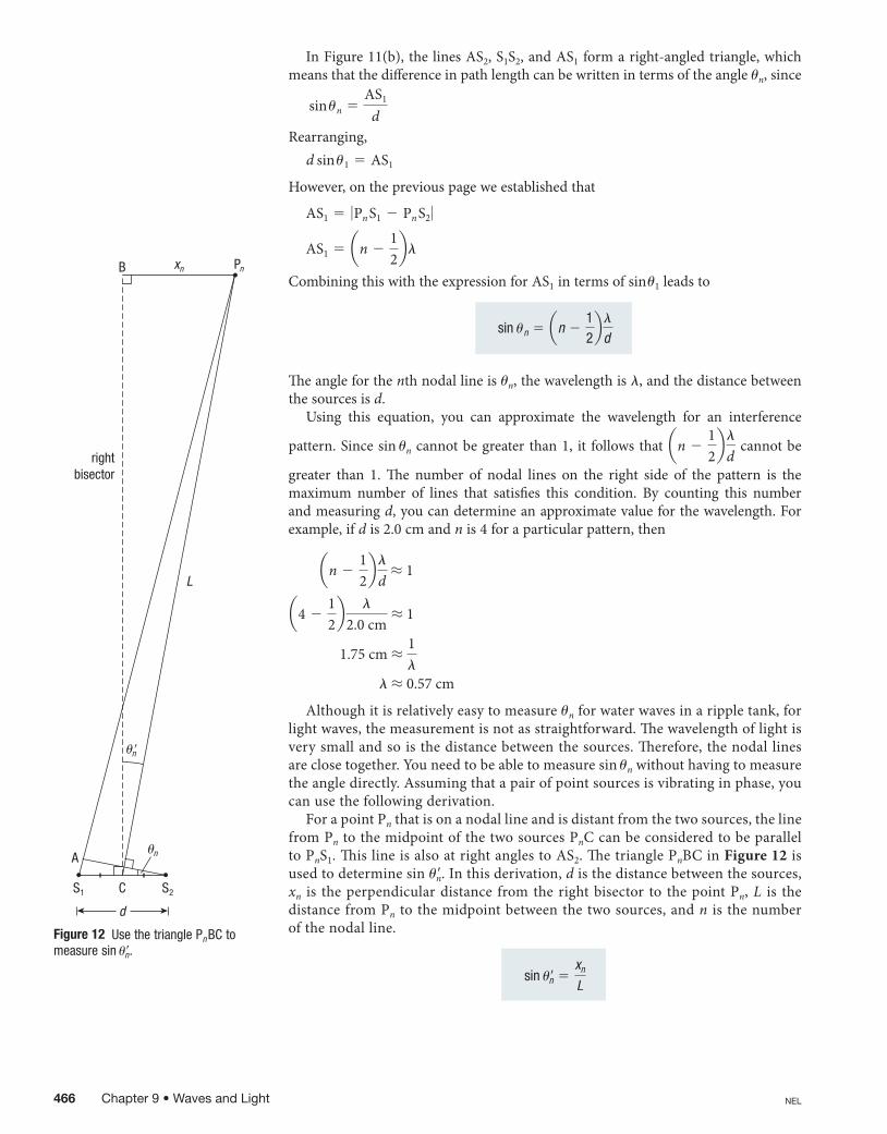
InFigure11(b),thelinesAS2,S1S2,andAS1formaright-angledtriangle,whichmeansthatthedifferenceinpathlengthcanbewrittenintermsoftheangleun,since
sin un 5AS1
dRearranging,
d sin u1 5 AS1
However,onthepreviouspageweestablishedthat
AS1 5 0Pn S1 2 Pn S2 0
AS1 5 an 212bl
CombiningthiswiththeexpressionforAS1intermsofsinu1leadsto
sin un 5 an 212bl
d
Theangleforthenthnodallineisun,thewavelengthisl,andthedistancebetweenthesourcesisd.
Using this equation, you can approximate the wavelength for an interference
pattern.Sincesinuncannotbegreater than1, it followsthat an 212bl
dcannotbe
greater than 1. The number of nodal lines on the right side of the pattern is themaximum number of lines that satisfies this condition. By counting this numberandmeasuringd,youcandetermineanapproximatevalueforthewavelength.Forexample,ifdis2.0cmandnis4foraparticularpattern,then
an 212bl
dL 1
a4 212b l
2.0cmL 1
1.75cm L1l
l L 0.57cm
Althoughitisrelativelyeasytomeasureunforwaterwavesinarippletank,forlightwaves,themeasurementisnotasstraightforward.Thewavelengthoflightisverysmallandsoisthedistancebetweenthesources.Therefore,thenodallinesareclosetogether.Youneedtobeabletomeasuresinunwithouthavingtomeasuretheangledirectly.Assumingthatapairofpointsourcesisvibratinginphase,youcanusethefollowingderivation.
ForapointPnthatisonanodallineandisdistantfromthetwosources,thelinefromPntothemidpointofthetwosourcesPnCcanbeconsideredtobeparalleltoPnS1.ThislineisalsoatrightanglestoAS2.ThetrianglePnBCinFigure 12isusedtodeterminesinu9n.Inthisderivation,disthedistancebetweenthesources,xn is theperpendiculardistance fromtherightbisector to thepointPn,L is thedistancefromPn tothemidpointbetweenthetwosources,andn is thenumberofthenodalline.
sin urn 5xn
L
B xn Pn
C
d
S1 S2
A
L
rightbisector
�n
�n�
Figure 12 Use the triangle Pn BC to measure sin u9n.
466 Chapter 9 • Waves and Light NEL
8160_CH09_p434-469.indd 466 4/30/12 9:47 AM

Figure 13isanenlargedversionofthetrianglewithbaseCS2inFigure12.Since
sin un 5
an 212bl
dand,sincetherightbisector,CB,isperpendiculartoS1S2,youcanseeinFigure13thatu9n5un.Sowecansaythat
xn
L5
an 212bl
d
C S2
d2
rightbisector
�
�n
�n�
or,
�n � � � 90°
�n� � � � 90°
�n� � � � �n � �
�n� � �n
Figure 13 Enlargement of the base triangle from Figure 12
The following Tutorial will demonstrate how to solve problems involving two-dimensionalinterference.
Tutorial 2 Interference in Two Dimensions
This Tutorial provides examples and sample calculations for the concepts of two-point-source interference.
The distance from the right bisector to a point P on the second nodal line in a two-point interference pattern is 4.0 cm. The distance from the midpoint between the two sources, which are 0.5 cm apart, to point P is 14 cm.
(a) Calculate the angle u2 for the second nodal line.
(b) Calculate the wavelength.
Solution (a) Given: n 5 2; x2 5 4.0 cm; L 5 14 cm
Required: sin u2
Analysis: sin un 5xn
L
u2 5 sin 21 x2
L
Solution:
u2 5 sin 21 x2
L
5 sin 21 a4.0 cm14 cm
b u2 5 178
Statement: The angle of the second nodal line is 178.
Sample Problem 1: Interference in Two Dimensions
9.3 Diffraction and Interference of Water Waves 467NEL
8160_CH09_p434-469.indd 467 4/30/12 9:47 AM
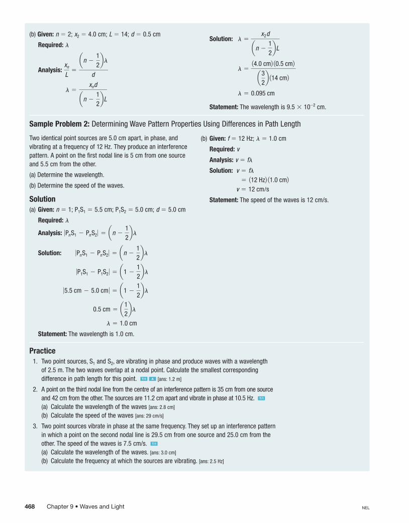
(b) Given: n 5 2; x2 5 4.0 cm; L 5 14; d 5 0.5 cm
Required: l
Analysis: xn
L5
an 212bl
d
l 5xnd
an 212bL
Solution: l 5x2d
an 212bL
l 514.0 cm2 10.5 cm2a3
2b 114 cm2
l 5 0.095 cm
Statement: The wavelength is 9.5 3 10-2 cm.
Sample Problem 2: Determining Wave Pattern Properties Using Differences in Path Length
Two identical point sources are 5.0 cm apart, in phase, and vibrating at a frequency of 12 Hz. They produce an interference pattern. A point on the first nodal line is 5 cm from one source and 5.5 cm from the other.
(a) Determine the wavelength.
(b) Determine the speed of the waves.
Solution(a) Given: n 5 1; P1S1 5 5.5 cm; P1S2 5 5.0 cm; d 5 5.0 cm
Required: l
Analysis: 0Pn S1 2 Pn S2 0 5 an 212bl
Solution: 0Pn S1 2 Pn S2 0 5 an 212bl
0P1S1 2 P1S2 0 5 a1 212bl
05.5 cm 2 5.0 cm 0 5 a1 212bl
0.5 cm 5 a12bl
l 5 1.0 cm
Statement: The wavelength is 1.0 cm.
(b) Given: f 5 12 Hz; l 5 1.0 cm
Required: v
Analysis: v 5 fl
Solution: v 5 fl 5 112 Hz2 11.0 cm2 v 5 12 cm/s
Statement: The speed of the waves is 12 cm/s.
Practice 1. Two point sources, S1 and S2, are vibrating in phase and produce waves with a wavelength
of 2.5 m. The two waves overlap at a nodal point. Calculate the smallest corresponding difference in path length for this point. T/I A [ans: 1.2 m]
2. A point on the third nodal line from the centre of an interference pattern is 35 cm from one source and 42 cm from the other. The sources are 11.2 cm apart and vibrate in phase at 10.5 Hz. T/I
(a) Calculate the wavelength of the waves [ans: 2.8 cm]
(b) Calculate the speed of the waves [ans: 29 cm/s]
3. Two point sources vibrate in phase at the same frequency. They set up an interference pattern in which a point on the second nodal line is 29.5 cm from one source and 25.0 cm from the other. The speed of the waves is 7.5 cm/s. T/I
(a) Calculate the wavelength of the waves. [ans: 3.0 cm]
(b) Calculate the frequency at which the sources are vibrating. [ans: 2.5 Hz]
468 Chapter 9 • Waves and Light NEL
8160_CH09_p434-469.indd 468 4/30/12 9:48 AM

Questions
1. Underwhatconditionisthediffractionofwavesthroughaslitmaximized? K/U T/I
2. Twoloudspeakersare1.5mapart,andtheyvibrateinphaseatthesamefrequencytoproducesoundwithawavelengthof1.3m.Bothsoundwavesreachyourfriendinphasewhereheisstandingofftooneside.Yourealizethatoneofthespeakerswasconnectedincorrectly,soyouswitchthewiresandchangeitsphaseby1808.Howdoesthisaffectthesoundvolumethatyourfriendhears? K/U
3. (a)Determinethemaximumslitwidththatwillproducenoticeablediffractionforwavesofwavelength6.331024m.
(b)Iftheslitiswiderthanthewidthyoucalculatedin(a),willthewavesdiffract?Explainyouranswer. K/U T/I
4. Twospeakersare1.0mapartandvibrateinphasetoproducewavesofwavelength0.25m.Determinetheangleofthefirstnodalline. T/I
5. Whatconditionsarenecessaryfortheinterferencepatternfromatwo-pointsourcetobestable? K/U T/I
6. Twoidenticalpointsourcesare5.0cmapart.Ametrestickisparalleltothelinejoiningthetwosources.Thefirstnodallineintersectsthemetrestickatthe35cmand55cmmarks.Eachcrossingpointis50cmawayfromthemiddleofthelinejoiningthetwosources. K/U T/I C A
(a)Drawadiagramillustratingthis.(b)Thesourcesvibrateatafrequencyof6.0Hz.
Calculatethewavelengthofthewaves.(c) Calculatethespeedofthewavesifthefrequency
ofthesourcesisthesameasinpart(a). 7. Astudenttakesthefollowingdatafromaripple
tankexperimentwheretwopointsourcesareinphase:n53,x3535cm,L577cm,d 56.0cm,θ35258,andthedistancebetweenidenticalpointson5crestsis4.2cm.Fromthesedata,youcanworkoutthewavelengthinthreedifferentways. T/I
(a)Carryouttherelevantcalculationstodeterminethewavelength.
(b)Whichpieceofdatadoyouthinkhasbeenincorrectlyrecorded?
Summary
• Diffractionisthebendingandspreadingofawavewhosewavelengthiscomparabletoorgreaterthantheslitwidth,orwherel$w.
• Interferenceoccurswhentwowavesinthesamemediummeet.• Constructiveinterferenceoccurswhenthecrestofonewavemeetsthecrest
ofanotherwave.Theresultingwavehasanamplitudegreaterthanthatofeachindividualwave.
• Destructiveinterferenceoccurswhenthecrestofonewavemeetsthetroughofanotherwave.Theresultingwavehasanamplitudelessthanthatofeachindividualwave.
• Waveswithshorterwavelengthsdiffractlessthanwaveswithlongerwavelengths.• Apairofidenticalpointsourcesthatareinphaseproduceasymmetrical
patternofconstructiveinterferenceareasandnodallines.• Thenumberofnodallinesinagivenregionwillincreasewhenthefrequency
ofvibrationofthesourcesincreasesorwhenthewavelengthdecreases.• Whentheseparationofthesourcesincreases,thenumberofnodallinesalso
increases.• Therelationshipthatcanbeusedtosolveforanunknownvariableina
two-point-sourceinterferencepatternis 0PnS1 2 PnS2 0 5 an 212bl.
Review9.3
9.3 Diffraction and Interference of Water Waves 469NEL
8160_CH09_p434-469.indd 469 4/30/12 3:21 PM