Embed Size (px)
Citation preview
Differentiated Traffic Engineering for QoS Provisioning
Vahid Tabatabaee, Bobby Bhattacharjee, Richard J. La, Mark A. Shayman University of Maryland, College Park, MD 20742, USA
Email: {vahid@eng, bobby @cs, hyongla@eng. shayrnan@eng} .umd.edu
Abstract- We introduce a new approach for QoS pmvisioning in packet networks based on the notion of differentiated traffic engineering (UTE). We consider a single AS neiwork capable of source based multi-path routing. We do not require sophisticated queuing or per-class scheduling at individual routers; instead, if a link is used to forward QoS sensitive packets, we maintain its utilization below a threshold. As a consequence, DTE eliminates the need for per-flow (IntServ) or per-class (DiffServ) packet processing tasks such as traffic classification, queueing, shaping, policing and scheduling in the core, and hence poses a lower burden on the network management unit. Conversely, DTE utilizes network bandwidth much more efficiently than simple over-provisioning.
I n this paper, we propose a complete architecture and an algorithmic structure for DTE. We show that our scheme can be formulated as a non-convex optimization problem, and we present an optimal solution framework based on simulated annealing. We present a simulation-based performance evaluation of DTE, and compare our scheme to existing (Gradient Projection) methods.
index Terms- Mathematical programmingl optimization.
r. INTRODUCTION
A. DTE overview In multi-service networks, different applications have dif-
ferent QoS requirements. In order to provide QoS in these networks, architectures such as DiffServ [6] have been pro- posed for QoS enforcement and bandwidth management. Ide- ally, QoS enforcement should be complemented with traffic engineering (TE) mechanisms for a comprehensive QoS archi- tecture, with TE applied over longer timescales. In this paper, we introduce “Differentiated Traffic Engineering (DE)”: a new traffic engineering architecture for QoS provisioning.
Under the D E model, the traffic engineering component performs the usual congestion control and load balancing functions, and is augmented to include functionality that provides paths with aliferentiuted utilizations for different service classes. The QoS requirement for each class of traffic is reflecte.d in its Maximum Permissible Utilization (MPU), for example, in this paper we’ll assume that all first class traffic is constrained to l ink with utilization less than 50%. Specifically, we assume that if utilization of a link 1 is below the MPU for a specific class e, then simple FCFS scheduling is sufficient to satisfy thc performance requirements for that class c over link 1. The objective of DTE is to ensure that the utilization of every link that carries ;i class of traffic is maintained below the appropriate MPU parameters.
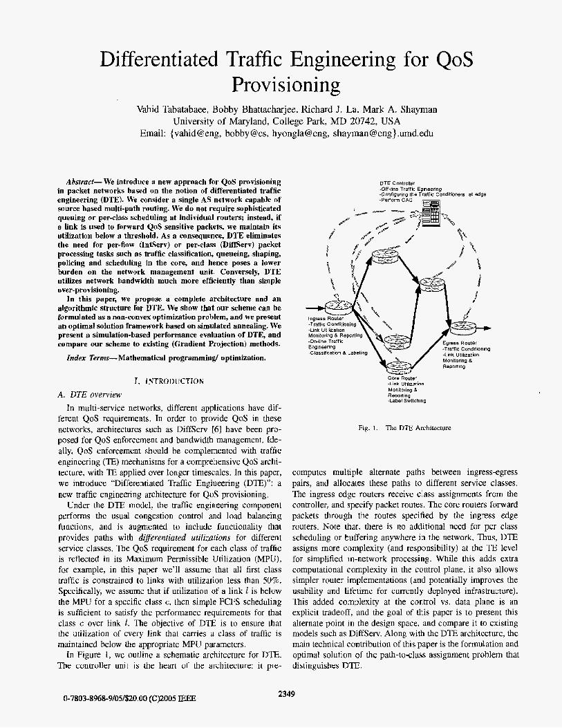
In Figure 1, we outline a schematic architecture for DTE. The controller unit is the heart of the architecture: it pre-
DTE Controller -Off-line Traffic Egineenng -Configuring the Traffr Conditioners at edge
core Router -Link Uti ler tmn Monitonng & Reporting -Label Swltching
Fig. 1. The D E Architecture
computes multiple alternate paths between ingressegress pairs, and allocates these paths to different service classes. The ingress edge routers receive class assignments from the controller, and specify packet routes. The core routers forward packets through the routes specified by the ingress edge routers. Note thac, there is no additional need for per class scheduling or buffering anywhere in the network. Thus, DTE assigns more complexity (and responsibility) at the TE level for simplified in-network processing. While this adds extra computational complexity in the control plane, it also allows simpler router implementations (and potentially improves the usability and lifetime for currently deployed infrastructure). This added complexity at the control vs. data plane is an explicit tradeoff, and the goal of this paper is to present this alternate point in the design space, and compare it to existing models such as DiffServ. Along with the D E architecture, the main technical contribution of this paper is the formulation and optimal solution of the path-to-class assignment problem that distinguishes DTE.
2349 0-7803-8968-9/05/$20.00 (C)2005 IEEE

B. Preliminaries and Motivations The ob-jective of network-level QoS is to provide pre-
dictable, or at least differentiated, levels of performance to packets and flows in a network. In general, there are two broad approaches to QoS provisioning in networks. The first approach is based on the over-provisioning, which tries to avoid any mechanism beyond what is already employed for best effort services in the networks. QoS is delivered by providing abundant bandwidth such that there is no congestion in the network. The second approach relies on bandwidth man- agement and ()OS enforcement techniques such as scheduling, policing and shaping of different classes of traffic at each routerlswitch.
The strongest argument in favor of the over-provisioning is its simplicity. Network management is much simpler in this approach, since the only parameter that needs to be monitored is rotaf link utilization, without regard to the classes of traffic that traverse any link. The number of parameters that need be configured and controlled is hence minimized, and failures malfunctions, and errors can be detected and resolved easier, Thus, it is not surprising that despite all theoretical and practical advancement for bandwidth management, over- provisioning is the deployed solution of current IP service providers IS].
However, even with over-provisioning, there is some need for bandwidth management. since it is difficult to predict traffic burstiness and peak demand. Thus, in reality, approaches that rely exclusively on simple over-provisioning lack the flexibility necessary to compensate for inaccurate network planning. Finally, over-provisioning requires (and relies on) frequent and expensive infrastructure upgrades.
The main issue with bandwidth management solutions for iP networks is their complexity. This complexity is manifested in both management and implementation. Even under DiffServ. (which is considerably simpler than IntServ), there 1s need for link speed packet classification, per class queueing, and scheduling in every router in the network. Further, ingress routers have to also shape, mark, and police packets. Such packet processing complexity not only has a direct impact on the hardware complexity, and cost, but it also increases the complexity and cost of the network management and operation. The number of parameters that have be set, con- trolled, and monitored grows quickly with network size, and often, it is difficult to detect and troubleshoot problems. In designing D E , we explicitly traded off this complexity at lower levelslfaster time scales (packet forwarding path) for somewhat more complexity at higher levelslslower timescales (traffic engineering).
C. TrafJic Engineering
The primary objectives for traditional uaffic engineering (E) in packet networks are (1) to avoid points of congestion in the network and to route traffic around these, and (2) lo provide alternate paths once the primary paths fail. TE is used to select feasible network paths that can provide specific service for each traffic class. Once these paths are selected. appropriate packet processing techniques (e.g. traffic shaping and per-node
scheduling) are used to enforce QoS requirements throughout the network. Soiirce-based Multipath Roirting: Under D E , we consider networks that support source based multi-path routing. We assume each source has a number of predetermined paths to each destination and can specify the path that each packet takes to the destination. ATM. and MPLS networks are good examples of networks capable of multi-path source based routings. Traffic engineering in these contexts have been studied before, e.g. in [71, 191. [181. The general uend here is to define a convex cost function for the links and finding an optimal routing that minimizes the overall network cost, For each source destination pair. the optimal routing specifies what portion of the traffic shouId be sent through which path.
In current networks, TE is recognized as a critical element of any bandwidth management solution. TE techniques have been introduced for QoS provisioning in DiffServ and MPLS networks [ l l , [16]. In our proposed model, TE algorithms ensure that the utilization of all links in the network comply requirements of the most stringent uaffic class that they serve. such that FCFS service is sufficient to enforce all QoS require- ments. Such traffic engineering allows us to eliminate the need for sophisticated packet processing and QoS enforcement in the core of the network. In an ideal DTE network, a limited set of the paths and links are over-provisioned to serve the QoS-sensitive traffic, while the rest of the network is utilized more efficiently and less restrictively for best effort traffic. Summug: In summary, compared to the other bandwidth management techniques, DTE removes the burden of QoS enforcement inside the network. This, in turn. simplifies the network management and operational paradigm. Compared to simple over-provisioning, DTE utilizes network resources more efficiently, and has enough flexibility to adapt to dynamic changes. Further, the more efficient utilization of network resources due to DTE implies lower infrastructure investment and upgrades.
D. Roadmup In section 11, we describe DTE, define its parameters, and
propose a general architecture and traffic engineering structure for its deployment, In section LII, we precisely define the path- to-class assignment (PCA) problem, which we consider as one of the main challenges of the DTE model. We show that the PCA is a non-convex optimization problem, and introduce an optimization algorithm based on simulated annealing. In sec- tion IV, we present simulation results and study performance of the algorithms proposed for PCA. Finally, we conclude in Section V.
11. DTE A. Assumptions and Dejnitions
We consider a network where capacity of all links are given and links utilization can be monitored at the session time scale. The network is capable of mulii-path source based routing. We consider two different classes of traffic in the network. say class 1 and class 2. These classes would typically map to real time and best effort traffic. The architecture and the algorithms

Fis. 2. A network with 2 source destination pairs and 4 paths.
Parameters
kc
%
R:,
TABLE I DEFINITIOX OF THE M A I S PARAMETERS
Dstinition
Maximum permissible utilization of a link carrying class c traffic
Traffic rate of class c on path p
Traffic demand of class c between source-destination pair (i, j )
TiJ lndex set of paths between the pair (i, j)
can be generalized to support multiple classes of service, but for simplicity, w e assume only two classes of service.
We represent the quality and performance requirements by Maximum Permissible Utilization (MPU) factor of class c, c = 1,2, k,. More specifically, if utilization of link 1 is below kc, then simple FCFS scheduling is sufficient to satisfy the performance requirements of class c over link 1. Path numbers are from 1 to P, and 7ri j is the path number set for source-destination pair ( i , j). The traffic rate matrix, [X]cxp, is the optimization control variable, where C is the number of classes and P is the number of paths. The control element zcp specifies the class c traffic rate on path p. We assume that, RE, which is class c traffic demand from i to j, is also available. A feasible solution satisfies the traffic demand constraints, which implies:
We summarize the definition in table I. The simple network in Figure 2 gives and example to clarify the parameters and the problem. There are two source-destination pairs (1,3) and (2,4). The class 1 and 2 traffic demands for (1,3) are Ri3 and Rf3 respectively, and are Ri4 and R& for (2 ,4) . There are 7 links in the network and link 1 capacity is q. There are four specified paths in the network, the first two are for the (1,3) and the next two for the (2,4) pair, i.e., ~ 1 3 = {l:2) and ~2~ = {3,4). Our objective is to specify the class 1 and 2
traffic rate over each path. The traffic rates for the path p are qP and q,. Hence. there are total of 8 parameters (4 paths times 2 classes) to be specified. The traffic demand constraints imply that path 1 and 2 total traffic rate must be equal to the traffic demand of the pair (1,3), and similarly, path 3 and 4 total traffic rate must be equal to the traffic demand of the (2: 4) pair. DTE computes the traffic rate matrices and provide it 10 the source nodes. One possible solution in this example is,
which sends class 1 traffic over paths 2 and 3 and class 2 traffic over paths 1 and 4. Another possible solution in which class 1 and 2 traffic share the same path is?
We will define the link cost function later. The D E goal is to find the solution with minimum total link cost. such that utilization of all links that carry class c traffic are below the class c MPU.
B. DTE VJ. Difleen.: Architecture and Management Figure 1 shows the proposed DTE architecture. The DTE
controller manages operation of the DTE elements and al- gorithms. More precisely, the DTE controIler monitors link utilization, and derives the nominal traffic demand. Moreover, the DTE controller participates in CAC and configures the traffic conditioners (shaping and policing) of the edge routers. Finally, the DTE controller is responsible for traffic engineer- ing and providing paths for different classes of lraffic in the network. The ingress edge routers specify paths for packets based on their destination and service class, perform traffic conditioning and buffer packets going out on the same link in a single FIFO queue. The egress routers shape the aggregate traffic that exits the network according to the configuration given by the DTE controller. The core routers simply perform routing of the packets through the predetermined paths using FIFO queueing.
The D E architecture looks similar to the DiffServ archi- tecture [6], with a bandwidth broker for network manage- ment [ 121; however, the function and role of certain elements are different. The DiffServ architecture was originally pro- posed by the IETF as a scalable alternative method to the IntServ for supporting QoS in IF networks. The DiffServ objective is to simplify packet processing in the network core and to shift the processing and QoS enforcement to the network edge.
In the DiffServ architecture, edge routers classify packets to different classes. Then, they compare each class of service traffic against its pre-defined profile and mark, shape and drop packets accordingly. Finally, a multi-class scheduler is used IO schedule packets out of the edge routers. The core router schedule and often shape each class of traffic based on the classes Per Hop Behavior (PHB).
Despite its relative simplicity 10 the IntServ. managing of a medium size DiffServ based network is still a difficult and time
235 I

TABLE 11 DTE YS. DIFFSERV WITH TE: REQUlREMENTS COMPARISON
(Path Selection and Routing;
consuming task 1151. The PHI3 of the core routers still need to be configured and monitored under DiffServ. The ultimate objective o€ the D'IE is to come up with a simpler solution than DiffServ for providing QoS in networks.
In order to use the network resources efficiently, Diff'Serv should be complemented with a TE solution that is capable of multi-path source based routing [ll, [161. The DTE model also assumes that multi-path source based routing is feasible in the network. This is possible for e.g., in an MPLS domain, or more generally, an overlay architecture that provides this functionality for an IP network [21.
We compare requirements of a DiffServ architecture com- plemented with a multi-path source based traffic engineering solution with the proposed DTE architecture. The comparison is summarized in Table 11.
The DTE controller task is simpler than the responsibility of a DiffServ bandwidth broker augmented with a traffic engineering solution. The bandwidth broker has to configure the edge and core routers traffic conditioners and scheduiers, whereas in the D E there is no traffic conditioning and scheduling in the core of the network. The bandwidth broker is required to monitor PHB performance on every link and router in the network, whereas in the D E , the controller needs to monitor the total link utilization. We will elaborate on the multi-layer structure of the traffic engineering for DTE in the next sections. Basically the only, additional functionality for DTE is Path to Class Assignment. We propose algorithms for path assignment and illustrate that they need to work on a very slow time scale and hence, they are not the bottle neck of the system.
Io the DiffServ architecture, the core routers perform scheduling and traffic conditioning and keep every class of service state to enforce the required PHBs. DTE core routers do not need these functionalities.
DiffServ edge routers should enforce traffic conditioning to all classes of traffic that enter the network. The DTE edge routers need to perform traffic conditioning only on those packets that share a link with real time traffic in their path. Therefore, traffic conditioning would be less restrictive for
DTE Managemenl
and Monitoring
- Nominal tratic Centralized algorjthm demand +lSenmg up and tearing down the
rovles. -Set of paths -
Path lo crsssnssignme~~c Centralzed algonthm. Asslgnmenl oftheparhs io classes 01 traf ic.
-demand. Sei of paths
N o m h l IraHicdistrbuljon
*Nominal link utilization
Dtstributed Algonthm On-line load drstribuiion btween Lhe paths
demand, -Sei of paths.
Assgnmenlol paths
keks I
Days
lours
;ession me
$ s a b
Fig. 3. Multi-layer Algorithmic Structure for D E .
D E and we can utilize network resources more efficiently.
C. Fimtional Srructure of the DTE
In this section, we review the four main blocks specified in Figure 3 (DTE management and monitoring and three TE blocks). Note that the time scale in the figure is for qualitative purposes and the exact values depend on the implementation. The D E management and monitoring unit is responsible for requesting new output from the three traffic engineering algorithms in Figure 3, passing them the input data, gather- ing their outputs, estimating the nominal and on-line traffic demand matrices. DTE management unit also interacts with other network management and control units. In that respect, it participates in the CAC process and set the traffic conditioning parameters at the edge routers. We assume that all blocks have the up-to-date information about the network topology and link capacity, and we focus on the algorithmic aspects of the TE.
The Path Selection and Routing [PSR) algorithm is respon- sible for inserting and removing paths between h e input and output ports. We will not elaborate on the PSR algorithms in this paper and assume that the se1 of paths are (pre-)computed and available. PSR would work based on the nominal traffic demands. The management and monitoring unit calculates and send the nominal traffic demand to the PSR. The traffic demand can be derived from the Service Level Agreements (SLA), measurements and traffic history [31, [141. In our architecture, the PSR algorithm is centralized in the DTE controller. The PSR updates palhs in a slow time scale (at leas[ in the order of many hours), since it is not either possible or
2352
desirable to insert and tear down paths and disrupt ongoing traffic in a network in a faster time scale.
Once palhs are selected. the management unit sends this information, together with the nominal traffic demand to the Path to Class Assignment JPCA) algorithm. The PCA uses this information to assign paths to different classes of service and after finding the desirable solution sends it back to the management unit.
We focus on the PCA problem in the rest of the paper. PCA assigns paths. and consequently links, to either class 2 or class 1 and 2 traffics. Maximum utilization for a link assigned to class 2 traffic is k2 and for a link assigned to both classes is kl. PCA works based on a link cost, which is a function of the link assignment, capacity and nominal traffic rates. The objective is to minimize the network total link cost. The PCA algorithm is also centralized in the DTJ3 controller. In section 111, we focus on the PCA and formulate it as an optimization problem. We illustrate that PCA is inherently a non-convex optimization problem and introduce algorithms to solve it.
After receiving the PCA output, the Management and Mon- itoring block activates either the load distribution or the PSR algorithm. It activates the Load Distribution algorithm if the performance of the PCA is acceptable; otherwise, it activates the PSR to consider a modified set of paths.
The PCA can be activated more frequently than the PSR. However, it is not practical to assume that the PCA can adapt and compensate for short term traffic fluctualion that occurs at the scale of the session time. Instead, a separate load distribution unit is designed to compensate and react to the short term traffic demand fluctuations.
The path assignments and the monitored traffic demand are inputs to the load distribution algorithm. Role and charac- teristics of this unit is simiIar to the other proposed online distributed traffic engineering solutions [71, [91, and we can use same algorithms with he appropriate cost function. Note that the load distribution unit works based on the monitored traffic demand matrix which includes the short term traffic fluctuations, whereas PCA and FSR use the nominal traffic demand that filters out short term fluctuations.
The load distribution algorithm input is real time traffic demand, and it updates traffic demand and link utilization data in a very short time scale (proportional to the session time). The load distribution works in conjunction with the CAC unit and traffic conditioning at the edge for QoS enforcement at a very fine grained time scale. We consider a distributed implementation for the load distribution aIgorithm in our architecture. Every link utilization is sent to the source nodes that use it in a path. Source nodes use this information and the path assignments to distributively perform the gradient projection method for load balancing.
The management and monitoring unit monitors the link utilization and if it concludes that the load distribution unit can not come up with a good solution, it employs other mechanism. For example, i t can use more restrictive traffic conditioning at the edge, activates PCA for modified assign- ment of paths, or activates PSR for modified set of paths.
I
111. PAT11 TO CLASS ASSlGNMENT
PCA is located in the D E controller and is the main distinguishing feature of the DTE from other TE approaches. Therefore, in order to show that the DTE architecture is feasible, it is critical to provide appropriate algorithm for PCA. In this section, we focus on the PCA problem and provide optimization algorithms for it. The nominal traffic demand matrices and paths are inputs to PCA. PCA assigns a path either io class 2 traffic or to both class Z and 2 traffic. The path assignment explicitly specifies maximum link utilization. Maximum utilization of link 1 is kl, if it is in a path assigned to both classes of traffic, and it is k2 otherwise.
The main issue with the PCA optimization problem is non- convexity. Because of non-convexity, common optimization techniques such as gradient pmiection are not appropriate for this problem. I n the following, we first show that the problem is non-convex, and provide a sub-optimal solution based on he gradient projection method. Then, we use simulated annealing technique with a nested gradient projection to find the optimal solution.
A . Integrated Approach and Non-comwxip The most common approach for Traffic engineering is to
choose an appropriate link cost function and find the feasible solution that minimizes the total link cost. Local search op- timization algorithms such as gradient projection method [7], 191, 1181 can be used to find the optimal solution. Link cost is usually a function of the link utilization. However, the DTE problem is more complex: link cost should be a function of class 1 and 2 traffic rates. We define, q, one possible candidate for link cost function;
if ul + wl 2 k2Hcr, (4)
I where and vu1 are link 1 class 1 and 2 traffic rates respec- tively, and H is a constant smaller but close to 1.
The cost function is defined for three separate cases. To better understand, we focus on the case, ul -t I I ~ < kll-lq. The cost function has two terms; the first (second) term can be interpreted as the average virtual delay of the class 1 (2) traffic. It is the average delay for class 1 (2) traffic if the capacity of the link is k l q ( k ~ c l ) and the queue behaves as an MIMI1 queue. If the class 1 12) traffic rate is non-zero, the first (second) term ensures that the link cost grows exponentially to infinity if link utilization gets close to the MPU of the class 1 (2) traffic. Therefore, this cost function works as a penalty function to impose the MPU requirements,
2353

c1= 12
as
.......... j ; i ..I..'
*.*....... ... ..... i ............ -:
I *.. '
' \
-. i
.. ........ ........ I .... .......
... -
......... \.
Class I lraflic rale
Fig. 4. ( U . v ) varies on the line connecting (0.8) to (4. U).
Cost function 7 for a link with capacity 8, when the rate vector
The gradient pro-@ion method is applicable if the cost function is differentiable for all (U, e ) E R2. The second and third cases for the cost function are inserted to ensure differ- entiability. The cost function increases exponentially when the utilization gets close to the MPUs. and it is differentiable with respect to U[ and vi.
UnfortunateIy, the cost function is not convex. In Figure 4, we plot link cost, and class I and 2' traffic rates versus class 1 traffic rate. Link capacity is 8, class 1 and 2 traffic rate vary on the line 2u +- w = 8 between the points (4; 0) and (0.81. Clearly. the cost function is not convex and hence, the conventional local search algorithms do not always converge to the optimal solution.
The next natural question is whether it is possible to define an appropriate convex cost function. Unfortunately, the answer seems to be negative and the non-convexity appears to be an inherent characteristic of the PCA problem. We clarify this with an example.
Consider the simple network consisting of two parallel links between the single source-destination pair in Figure 5. Both links capacities are 12 units, class 1 and 2 traffic demand are 5 and 9 respectively. Suppose that X-1 and k2 are 0.5 and 1 respectively. One feusibk solution is to send class 1 and 2 traffic on separate links. Assume that the optimal solution, XI is,
X I = ( " I " ) 2xsomc O < a r < 5 , O S b 5 9 . ( 5 )
Due to the symmetry, there is another optimal solution X2,
5 - a a ( b 9 - b xz =
Therefore, there are two optimal solution unless,
but this can not be an optimal solution since it is not feasible and we know that a feasible solution exists.
We proved that PCA has two optimal solutions in this case. Obviously, there can not be more than a single minimum for a convex function, and hence PCA is a non-convex optimization problem.
R1.5 R2 = 9
c2 = 12
Fig. 5. destination pair.
A simple network with two parallel links between the source-
Even though i t is not clear that the local search optimization methods converge to a good solution. we can still apply them and settle for sub-optimal solutions. We consider an algorithm based on the gradient projection method and the link cost function defined in (4) and call it the Integruted Approach. Obviously. there is no guarantee that such an algorithm will converge to the optimal solution. The final solution depends on the initial point, and even when there is a feasible solution for MPU constraints, the algorithm may not be able to find it. The main advantage of the Integrated Approach is its simplicity. The gradient projection methods are well defined and studied for traffic engineering. We can run these algorithms on-line, distributed and asynchronous at the source nodes.
In the next section, we present a two step approach that breaks the PCA problem into two nested optimization prob- lems, such that one problem is non-convex and we use the simulated annealing technique, whife the other is convex, which we use the gradient projection method to solve it.
B. Nested Approach: Simulated Annealing Simulated annealing is a randomized optimization algorithm
that can converge to the global optimal solution [lo]. The optimization space is specified through the state variabIe and cost is function of state. The cost function is usually referred to as the energy function in simulated annealing literature and the objective is to find the state with minimum energy. At every time k the simulatd annealing algorithm is at a random state s k , and s k converges to the slate with minimum cost as k goes to infinity. Assume that an irreducible Markov process governs the state update process. We use the Markov model conditional probabilities for state SL to select another state. tk. State at time k + 1 is either Sk, or si;. Let,
(8)
then ~ k + ~ = Ck. with probability exp(-AEk+l/T,t+l), and s k + l = sk otherwise. Therefore, if state Sk has a lower cost than the current state it will be selected for k + 1. Even if S;, has a higher cost than the current state, it will be selected with probability ezp(-AhEk+1/T'+l).
The parameter T k is called temperature at time I;. It has been proven that if the starting temperature is sufficiently large and it converges to zero sufficiently slowly, the state variable converges to the minimum cost state.
AEk+l = COST(gk) - COST(sf;)
If AEk+l < O, then S k + l = 8-k. If AEk+l 2 O,
2354

Initially, at high temperatures, the ncwly generated states are usually selected and the process can escape from the local minimums. As the temperature gets lower, the probability of selecting a state with higher cost diminishes and the process converges.
Siiniilafed Annealing applied lo the PCA: In our formula- tion. the state variable is a P dimensional binary vector that specifies paths to class assignments. If path p state value is zero, it can only serve class 2 traffic. If path state value is 1. it can serve both classes of traffic'.
Next. by means of an example. we describe how we select the neighbor state <L at every step I ; . The process of selecting a neighbor state is ilIustrated in Figure 6, where we use the same network as in Figure 2. Paths and links with state 1 (0) are specified by solid [dashed) lines. Figure 6-a specifies the current state, where paths 1 and 4 states are one, and paths 2 and 3 states are zero. To select one of the neighbor states randomly. we first choose one of the source destination pairs uniform randomly. In this case, we have picked the pair (1,3). Then, we uniform randomly select one path associated with the selected pair. We change state of the selected path and update the link states accordingly. In the example, path 1 is selected and its state is changed. The outcome is in Figure
with one exception; if state of all selected source paths are zero and that source has class 1 traffic demand, we select another path associated with that source in random. This is exactly the case for source Z in our example. Notice that both parhs from node 1 has state 0. If this happens, we randomly select another path of the selected source, and change the path state. In the example, path 2 is selected and its state is changed to I; the final result, S;;, is shown in Figure 6-c.
In this way, for every source-destination pair with non-zero class 1 traffic rate. there is at least one path to serve class 1 traffic. Furthermore, if there is a source with only one path we fix the path state and will not change it in the process. If the singIe path source has non-zero class 1 traffic rate, path state is one and zero otherwise.
We still need to explain the state cost function. To that end, we define the virtual capacity for link 1:
6 -b. The result would be the state
klcr if link 1 belongs to a path p with state 1 '' = { k2q otherwise. (9)
Cost of the link 1 is,
where wl is the total traffic rate of link E and H is a constant smaller but close to I . A similar cost function is defined in [17], but we replaced capacity with virtual capacity. I t is easy to verify that the cost Function is convex and
' ln general. for c > 2. path state sp is in { O , - . . , c - 1). If sp = k, p can serve traffic classes c - k to c.
Fig. 6. Process of selecting the neighbor state in a simple nerwork. The links and paths with state 1(0) are shown with solid(dashed) lines. The current state, the intermediate stage and the neighbor state are shown in the figure.
differentiable. For W L < H 4 , ~l is the average delay of an MM/l queue with TUL arrival rate and capacity et. Similar to the definition of 771, the second case is inserted to ensure differentiability and exponential growth of cost as rate gets close to the virtual capacity. The total cost is,
L
COST = x y ~ . l=I
Clearly, cost is a convex function of the rate vector and we can use gradient projection method to find the minimum cost.
Therefore, for a fixed state vector s and class 1 and 2 traffic demand matrices, we first compute the virtual capacity of all links. Then, we solve the following convex optimization problem to find the state s cost,
s .t 112) c zcp = I $ for all z, j , c.
P E T i j
At every step I; of the simulated annealing algorithm, candidate state S;; is selected. Then, we use the gradient
2355

pro-jection method to solve 12 and derive the state cost. In reality, we store cost of visited states to avoid recalculation of state cost, Ultimately, we select s k t l Erom s k and s’k using the simulated annealing probabilistic rule.
Before ending this section, we briefly explain the load distribution unit, since any of the previously proposed on-line traffic engineering algorithms such as [7], [9] can be used for this purpose. The path assignment are determined by the PCA unit and passed to the load distribution unit.
Taking into accounl the path assignments. the load distri- bution algorithm uses the relation (9) to determine the virtual capacity of the links. Then, it uses the gradient projection or its variants to solve the optimization algorithm given in (12). However, it uses short term on-line estimations of traffic demand variables r& to calculate the link rate, wl. in relation (IO). The load distribution is carried out by the source nodes in a distributed and asynchronous manner, whereas PCA is computed centrally at the D E controller.
Even though source nodes carry out the load distribution algorithm. status and performance of the system is monitored by the DTE controller. If the performance deteriorates unac- ceptably. the D E controller should employ other mechanism such as traffic condilioning at the edge routers and activation of the PCA and PSR with the updated nominal traffic demand to restore the performance.
Iv. SIMULATION RESULTS AND DISCUSSION
In this section, we present the simulation results and discuss some characteristics of the PCA algorithm. We first compare the performance of the Integrated Approach and the Nested Approach in a simple network. We illustraie that the Nested Approach works better and outperforms the Integrated Ap- proach. In the next section, we focus on the behavior of the PCA when the first class traffic demand increases. Finally, we study the performance of the PCA in a larger size network. We also study the sensitivity of the performance to the deviations in the traffic demand matrix. For the simulations we assume that the MPU for class 1 (2) traffic is 0.5 (1).
A. Integrated vs. Nesred approach Consider the simple network shown in Figure 7. There
are three source-destination pairs, {( 1,4)? (2.5): ( 3 , 6 ) } and 7 paths. The network links are divided into three layers, layer 1 is connected to the source nodes, layer 3 to the destination nodes and layer 2 links are between layer 1 and layer 3 links. Traffic rate of class 1 and 2 traffic from every source are 4 and 7 units respectively. Capacities of the three, second layer links are specified in the figure and are 14. 23, and 14 respectively. Capacity of all other links is 10 units. The first 2 paths belong to the sourcedestination ( l ,4 ) and are (1 , a, d, 4). (1, b: e, 4) respectively. Paths 3 - 4 and 5 belong to the source-destination (2 ,5) and are (2, a, d, 5 ) , (2: b, e, 3 ) , [a, c, f, 5 ) respectively. Paths 6 and 7 belong to source-destination (3,6) and are (3, b: e: 6 ) , (3, e, f, 6) respectively.
Given these assumptions, one feasible solution is to send class I traffic through the upper and lower links and class
SmndLaYw Links Derlnnlion Nodes
Fig. 7. A simple network with 3 source destination pairs. {(1.4),(2,5),(3,6)} and 7 paths. 7 h e three middle layer links are bandwidth bottle necks and their capacities are specified on the graph.
2 traffic through the middle link of the 2nd layer. The corresponding path state vector is,
s1 = (1 ,c4~:0 ,1 ,0~1) , (13)
and the optimal load distribution for this state is,
Cost of s1 is 49.69 and turns out that s1 has the minimum cost and ideally, the DTE will converge to this solution. Let $2 be the complement of the SI,
s 2 = ( o , l ~ o , l , o : l , o ) . (15)
The optimal load distribution for s2 is,
) (16) 0 4 0 4 0 4 0 7 0 3.5 0 3.5 0 7 . xz =
Cost of 32 is 84.31 and i t is has the second lowest cost, even though its state vector has the maximum hamming distance from SI. Therefore, the optimization surface is non-convex. In our simulations, the Nested approach based on the simulated annealing converges to the minimum cost state sl.
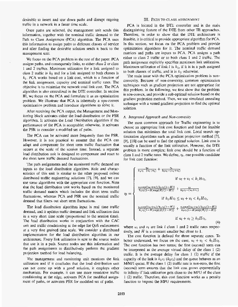
Next we. test the Integrated Approach. We chose the ini- tial points randomly and ran the simulation 100 times. As we expect, the final solution, depends on the initial point. We observed four possible final solutions for the Integrated Approach. We summarized the results in Table In, where cost. load distribution and percentage of convergence to the solutions are given. The third row represents two symmetric solutions with the same cost. Only, the first row solution satisfies the MPU conditions, and 25% of the experiments converged to it. We expect that the performance of the Integrated Approach degrades unacceptably for larger size networks and hence, we focus on the Nested Approach for the rest of simulations.
B. Dynamic behavior of rhe PCA In this section, we study the effect of traffic demand
variation in the PCA path allocation. Figure S shows the simulated network, which is a modified version of the net- work used in [ I l l . There are 8 source-destination pairs,
2356
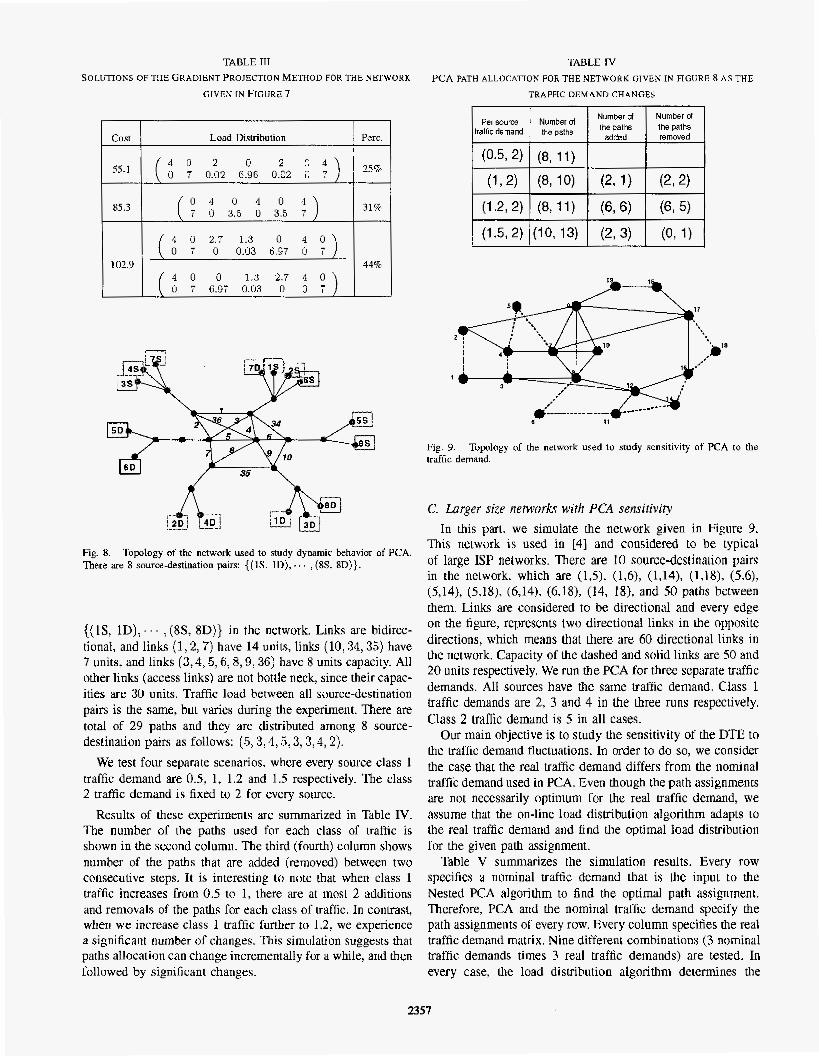
TABLE I11 SOLUTIONS OF THE GRADIENT PROJECTION METHOD FOR THE NETWORK
GIVEX IN FIGURE ?
cost
TABLE IV PCA PATH ALLOCATIOK FOR THE NETWORK GIVEN IN FIGURE 8 AS THE
TRAFFIC DEMAND CHANGES
Load Distribution Perc.
102.9
4 D 2.7 1.3 0 4 0 0 7 0 0.03 6.97 0 7
( 9 6.97 0.03 '; ) 44%
0 1.3
Fig. 8. There are 8 source-destination pairs: {( lS. lD), . . . , (8s. SD)}.
Togology of the network used to study dynamic behavior of PCA.
((IS, lD), . . . ,(SS. 8D)) in the network. Links are bidirec- tional, and links (1,2, 7) have 14 units, links (10: 34,35) have 7 units. and links (3 ,4 ,5 ,6 ,8,9,36) have 8 units capacity. All other links (access links) are not bottle neck, since their capac- ities are 30 units. Traffic load between all source-destination pairs is the same, but varies during the experiment. There are total of 24 paths and they are distributed among 8 source- destination pairs as follows: (5,3,4,5: 3 ,3 ,4 ,2 ) .
We test four separate scenarios, where every source class 1 traffic demand are 0.5, 1, 1.2 and 1.5 respectively. The class 2 traffic demand is fixed to 2 for every source.
Results of these experiments are summarized in Table IV. The number of the paths used for each class of traffic is shown in the second column. The third (fourth) column shows number of the paths that are added (removed) between two consecutive steps. It is interesting to note that when class 1 traffic increases from 0.5 to 1, there are ai most 2 additions and removals of the paths for each class of traffic. In contrast, when we increase class 1 traffic further to 1.2, we experience a significant number of changes. This simulation suggests that paths allocation can change incrementally for a while, and then followed by significant changes.
Per source Number of tralficdemand Ihe paths
Number Of lhe removed
I \
Fig. 9. traffic demand.
Topology of the network used to study sensitivity of PCA to the
C. Larger size nemorks with PCA sensitivity In this part. we simulate the network given in Figure 9.
This network is used in [41 and considered to be typical of large ISP networks. There are 10 source-destination pairs in the network, which are ( l ,S) , (I$), (1,141, (1,18), (5,6), (5,14), (5,18), (6,141, (6,18), j14, 181, and 50 paths between them. Links are considered to be directional and every edge on the figure, represents two directional links in the opposite directions, which means that there are 60 directional links in the network. Capacity of the dashed and solid links are 50 and 20 units respectively. We run the PCA for three separate traffic demands. AH sources have the same Uaffic demand. Class 1 traffic demands are 2, 3 and 4 in the three runs respectively. Class 2 traffic demand is 5 in all cases,
Our main ohjective is to study the sensitivity of the DTE to the traffic demand fluctuations. In order to do so, we consider the case that the real traffic demand differs from the nominal traffic demand used in PCA. Even though the path assignments are not necessarily optimum for the real traffic demand, we assume that the on-line load distribution algorithm adapts to the real traffic demand and find the optimal load distribution for the given path assignment.
Table V summarizes the simulation results. Every row specifies a nominal traffic demand that is the input to the Nested PCA algorithm to find the optimal path assignment. Therefore, PCA and the nominal traffic demand specify the path assignments of every row. Every column specifies the real traffic demand matrix. Nine different combinations (3 nominal traffic demands times 3 real traffic demands) are tested. In every case, the load dislribution algorithm determines the
2357

TABLE V MAXIMUM UTILIZATIOK OF L I N K S THAT CARRY CLASS I A N D 2 TRAFFlC
(U1 map) A N D LINKS THAT CARRY CLASS 2 TRAFFIC ONLY (U2 ”).
IBemand 11 Demand ! I I
optimal traffic rate of all paths vector for the given real traffic demand (column) and path assignment (row), Table V gives the maximum link utilization for links with state 1 (Ul and all links (U , may).
Recall that we would like to keep the utilization below the MPU, which is 0.5 for links with state 1, and 1 for l inks with state 0. Obviously, if the real traffic demand is less than the nominal traffic demand the performance is expected to be better. The last row of table V is optimized for the nominal traffic demand of (4: 5). The maximum utilization of the links with state 1 (O) , when the real traffic demand is also (4 ,5) are 0.4267 (0.818), which are below the corresponding MPU values. As. we expect, when the real traffic demand is less than (4:5), the maximum utilization of the links drops and we do even better. Further, if we compare two cases that real traffic demand is (3,5) and nominal traffic demands are (3,5) and (4,s); the,maximum utilizations are very close. The same trend is repeated between the cases with real traffic demand (2 ,5 ) and nominal traffic demands of ( 2 , s ) and (4,s).
The main conclusion here is that the PCA performance sensitivity to the traffic demand deviations is not symmetric. The performance is more sensitive when the demand deviates above the nominal value than when it deviates below the nominal value. It is not desirable nor practical to run the PCA algoritbm very frequently in a network, since it results in frequent updates of the path states. Therefore, the nominal traffic demand should be calculated such that the resulted path assignments are useful for a wide range of real traffic demand fluctuations. The result of these simulations imply that it is better to be conservative in the calculation and estimation of the nominal traffic demand and work with nominal traffic demand that is larger than the real traffic demand. In this way, if the real traffic demand increases, it will get closer to the nominal traffic demand and performance is close to the optimum. If the real traffic demand stays unchanged or decreases, we know that the load distribution can work well and compensate for the difference between the nominal and real traffic demand as seen in the simulation results.
v. CONCLUSION AND FUTURE WORK
In this paper. we introduced D E , a new model for pro- viding QoS in networks. DTE is applicable to networks that perform multi-path source based routing. The main idea behind
DTE is to allocate paths to different classes of service and over-provision paths that carry quality sensitive traffic. In this way. there is no need for per-class scheduling and management of traffic inside network. We proposed a general architecture and traffic engineering structure for D E . Path to Class As- signment (PCA) is the distinguishing algorithm and one of the main challenges of DTE. We showed that PCA is non-convex optimization problem and developed an optimization algorithm based on the simulated annealing technique for It. We provided simulation results and studied performance, dynamic behavior and sensitivity of the developed algorithms.
In this paper, we assumed that the set of paths are available. In reality, paths have a profound impact on the performance of the DTE and it is essential to develop algorithms for Path Selection and Routing (PSR) in future. It is desirable to come up with a mechanism that can incrementally add and remove paths from the network, and creates minimal disruption on the traffic flow. Moreover, path selection should be resilient to the changes in the traffic demand.
DTE architecture and management is another interesting venue for future research. Development of the DTE man- agement and monitoring rules and algorithms for requesting modified set of paths and path assignments from PSR and PCA, estimating of the nominal traffic demand, configuring the traffic conditioners at the edge routers as well as development of communication protocol for the D’IE controller and the routers are all interesting research problems.
REFERENCES
1.E Akyildiz, et al., “A new traffic engineering manager for DLff- Serv/MPLS networks: design and implementation on an IP QOS testbed,” Journal of computer communications, Elsevier. 26(2003). D.G. Andersen, H- Balakrishnan, M. E Kaashoek. R. Moms. “Resilient overlay networks,” ACM Symposium on @eraling Sy5tenis Principles. Banff, Canada. October 7001. T. Anjali. C. Scoglio, l.F. Akyildiz, G. Uhi, “A new scheme for traffic estimation and resource allocation for bandwidth brokers,” BWN LAB Technical Report BWN-02-J-32 G. Apostolopoutos. R. Guerin, S. Kamat, S. Tripathi, “Quality of service based routing: A performance perspective,” ACM, SIGCOMM. 1998. S . Bhattacharyya, “Design and operation of a large 1p backbone network,” Available on line at: http://www- net.cs.umass.edu/cmpci_59 I -453/notes/supratik.ppt. S. Blake, et al., “An architecture for differentiated services,” Informa- tional WC-2475, Dec. 1998. A. Elwalid, C. Jin, S. Low, and I. Widjaja, “MATE: MPLS Adaptive Traffic Engineering.’’ IEEE NFOCOM 2001, Anchorage, Alaska, ?001. V. Firoiu. 1. 1. Boudec, D. Towsley. Z. Zhang, “Theories and Models for Internet Quality of Service.” Pmcceding of IEEE, Aug. 2002. T. Guven. C. Kommaredy, R. J. La, M. A. Shayman, B. 3hattacharjee. “Measurement based optimal multi-path routing,” IEEE Infocam 2W4, Hong Kong, 2004. S. Kirkpatrick. C. D. Gelatt, M. P. Vecchi, “Optimization by Simulated Annealing.” Science. 220, 671-680. 1983. R. 1. La. V. Anantharam, “Utility based rate control in the lnternet for elastic traffic.” IEEUACM Tramactions on Networking. vol. 10(2), pp. 272.284, April 2W-. K. Nichols. V. Jackobson, L. Zhang. “A Two-bit Differentiated Services Architecture for the Internet,” Informational RFC-2638. July 1999. E. Rosen. A. Viswanathan, R. Callon, “Multiprotocol Label Switching Architecture.” RFC303 I . Jan. 2001. A. Sridharan et al., “On the impact of aggregation on the performance traffic aware routing,” IEEE INFOCOM 2001, Anchorage, Alaska, 2001. G. Stattenberger, T. Braun, “Performance of a bandwidth broker for DiffServ networks,” Kmmrurikatiun in verfeilten Sp?” 2093, Leipttg. Gamany, 2003
2358

[I61 I? Trimintzios, L. Cicorgiadis. G. Pavlou. D. Griffin. C.F. Cavalcanti, P. Ceorgastos. C. Jacquenet. “Engineering the Multi-service Internet: MPLS and IF‘-Based Techniques,” l€E€ fnl. ConJ on Ekcommzmicu- fions. Bucharest. Romania. 2001.
[ 171 F’. Trimintzios. T. Bauge. G. Pavlou. L. Georgiadis. P. Flzgkas. R. Egan. “Quality of Service Provisioning for Suppning Premium Services in IP Networks,” IEEE Globecuni 2002. Taipei. Taiwan, 2002.
[18] J. K. Tsitsiklis. D. P. Brrtsekas. “Distributed asynchronous optimal routing in data networks.” IEEE Trans. on Aukmatic Control, vol. 31. no.4, April 1986.
2359