Embed Size (px)
Citation preview

American Journal of Nano Research and Applications 2018; 6(1): 1-10 http://www.sciencepublishinggroup.com/j/nano doi: 10.11648/j.nano.20180601.11 ISSN: 2575-3754 (Print); ISSN: 2575-3738 (Online)
Review Article
Different Methods Used for the Synthesis of TiO2 Based Nanomaterials: A Review
Azad Kumar*, Gajanan Pandey
Department of Applied Chemistry, School for Physical Sciences, Babasaheb Bhimrao Ambedkar University, Lucknow, India
Email address:
*Corresponding author
To cite this article: Azad Kumar, Gajanan Pandey. Different Methods Used for the Synthesis of TiO2 Based Nanomaterials: A Review. American Journal of Nano
Research and Applications. Vol. 6, No. 1, 2018, pp. 1-10. doi: 10.11648/j.nano.20180601.11
Received: October 17, 2017; Accepted: October 30, 2017; Published: February 1, 2018
Abstract: Titanium dioxide is a widely accepted photocatalyst due to its high oxidation efficiency, non-toxicity, high photostability, chemical inertness and environmentally friendly nature. There are several number of attempt have been made to synthesize TiO2 nanomaterials with different methods. In this paper we have to show the effect of synthesis methods and their surface morphology with temperature. The different methods are used for the synthesis of different Titania based nanomaterials. These methods are sol-gel method, sol method, electrodeposition method, micelle and reverse micelle methods, direct oxidation, chemical vapour deposition method, hydrothermal method, solvothermal method, Ultrasonication methods and microwave method. In this paper, we are summarizing the synthesis methods, morphology of Titania and crystal structure of the TiO2 nanomaterials. We are also showing the different nanostructures of TiO2 materials.
Keywords: Titania, Nanomaterials, Hydrothermal, Sol-Gel, Solvothermal, Electrodeposition, Micelle
1. Introduction
Titania (TiO2) is a very important nanomaterial which has fascinated a great consideration due to its unique properties. Titanium dioxide TiO2 have tremendous advantages in solar energy transferring and photocatalysis of poison compounds in environment. Further, the strong oxidizing power of the photogenerated holes, the chemical inertness, and the non-toxicity of TiO2 has also made it a superior photocatalyst. TiO2 is found in 3 major crystalline forms namely anatase,
rutile and brookite. There are some other forms of Titania exists such as hollandite, collumbite, ramsdellite. These forms of Titania do not occur in nature but it can be synthesized in laboratory at high pressure treatment on anatase and rutile phase. The Brookite phase is not practically beneficial for different applications. It is unstable at room temperatures but it can exist at low temperature. The Rutile is the most stable form of Titania and highly used form. The Rutile and anatase phase’s shows the different nature and applications and both forms are usually compared [1-5].
Figure 1. Structure of different crystal structure of titanium dioxide [8].

2 Azad Kumar and Gajanan Pandey: Different Methods Used for the Synthesis of TiO2 Based Nanomaterials: A Review
Titanium dioxide that is used as the photocatalyst is mainly
anatase-type crystal structure. There are 3 kinds crystal structure of titanium dioxide. Figure 1 is showing the different phases of Titania. Generally, the physical/chemical properties of a material may be quite different for their various phase structures. The Titania anatase form is a tetragonal structure (with dipyramidal habit) and it is used as a photocatalyst under UV irradiation because it has band gap energy 3.2 eV. The Titania rutile phase is a tetragonal crystalline structure (with prismatic habit). It is mostly used as white pigment in paint. The Titania brookite phase is an orthorhombic crystalline structure [6-7].
TiO2 is a flexible material which has applications in solar cells, electrochemical electrodes, capacitors, paint pigments, sunscreen lotions, and it is also food colouring agent used in toothpastes [9]. The anatase form of Titania is mostly used due to of its high oxidative power and photocatalytic activity. The anatase form of Titania has higher potential energy of photogenerated electrons and negative conduction band edge potential, high specific surface area and non-toxic. It is highly photochemically stable compared with others forms of Titania and relatively inexpensive [10]. The Titania surface morphologies have mostly incorporated nanostructures for example nanotubes [11], nanowires [12], nanorods [13], and mesoporous structures [14]. There are several methods are used for the synthesis of Titania and Titania based nanomaterials such as sol-gel method [15], solvothermal method [16], hydrothermal method [17], chemical vapour deposition (CVD) [18], direct oxidation method [19], electrodeposition [20], Sonochemical method [21], and microwave method [22]. These methods mostly used for the synthesis of TiO2 nanostructured.
2. Synthesis of TiO2 Nanoparticles
The control of physiochemical properties (size, shape, morphology and composition) is the very important for the Titania synthesis [23-24]. It is very useful for the photocatalytic activity of Titania. So that we have to need methods employing for the synthesis of photocatalyst with desired properties. Moreover, the synthesis of Titania should be ecofreindly, economically and inexpensive [24]. Various synthesis methods have been tried for synthesis of Titanium dioxide and its composites are discussed below [24-26].
2.1. Sol-Gel Method
In the 1960s the sol-gel method was used first time for the synthesis of new materials with a variety of shapes, porous structures, thin fibers, dense powders and thin films. In the Sol-gel process, the conversion of liquid solution (Sol) to a solid gel phase (Gel) is occurring [7, 24]. A sol is formed by the colloidal particles in liquid. The colloidal particles are not dissolved in the sol, and they do not coagulate or sediment [7, 24]. It is a stable dispersion of colloidal particles in a solvent. While, gel is made up of a three dimensional continuous
network, which is encloses in liquid phase. In a colloidal gel, the network is built from agglomeration of colloidal particles [7, 24]. The particles in a polymer gel have a polymeric substructure made by aggregates of sub-colloidal particles. Usually, the sol particles may interact by Van der Waals forces or hydrogen bonds. A gel may also be formed from linking polymer chains. In most gel systems used for materials synthesis, the interactions are of a covalent nature and the gel process is irreversible [7, 24]. In a typical sol-gel process, TiO2 nanoparticles are formed by hydrolysis and polycondensation (de-hydration and de-alcoholation) reactions of Titanium alkoxide, to form oxopolymers, which are then transformed into an oxide network. The structure and properties of metal oxides is strongly dependent on the rate of hydrolysis and poly-condensation [24]. The factors responsible for the formation of metal oxides are: reactivity of metal alkoxide, water to alkoxide ratio, pH of reaction medium, nature of solvent and additives and reaction temperature [7, 24, 27-28]. Figure 2 is showing the TEM image of Titania prepared through the sol gel method. The particles are clearly seen in the Figure 2. The particles are observed in nanometric dimension. This method is used for the synthesis of nanoparticles of Titania. It is very suitable for the preparation of Titania based nanomaterials.
Figure 2. TEM images of TiO2 nanoparticles synthesized via sol-gel route
[Adopted from ref. 29].
2.2. Sol Method
In the sol method, the non-hydrolytic sol-gel processes occur and generally engage the reaction of TiCl4 with a range of different O2 donor molecules like a metal alkoxide or organic ether [24, 30]. Figure 3 showing the nanoparticle of Titania is prepared via two methods of sol- gel methods with an organic solvent [24]. The particle is observing in nanodimensions. Both the methods are used for the synthesis of Titania, slightly different in composition percentage of reactant. From the method I we have to get good particles while methods II give agglomerate of particles synthesized.

American Journal of Nano Research and Applications 2018; 6(1): 1-10 3
Figure 3. TEM image with Electron diffraction pattern of Nano TiO2 by (A)
Method I (B) Method II, [Adopted from ref. 31].
2.3. Hydrothermal Method
The hydrothermal reaction is usually done in steel pressure a vessel that is called autoclaves with or without Teflon liners under controlled temperature or pressure with the reaction in aqueous solutions [7, 24]. The temperature of reaction can be elevated above the boiling point of water, reaching the pressure of vapour saturation. The temperature and the amount of solution added to the autoclave mostly determine the internal pressure formed [7, 24]. The hydrothermal method is defined as any heterogeneous reaction in the presence of aqueous solvents or mineralizers under high pressure and temperature situation to dissolve and recrystallize the materials that are moderately insoluble under ordinary conditions [7, 24, 32]. In this process the solvent is used under high temperature (Usually between 100°C and 1000°C) and also high pressure (usually between 1 atm and 10,000 atm) that encourages the interaction of precursors during synthesis. If water is used as a solvent, the method is called as hydrothermal synthesis [7, 33]. In the Figure 4 is showing the synthesis of Titania nanowires via hydrothermal method. The Titania nanowires is the found in micrometer size. The nanowires of Titania are showing the higher surface area than the other crystalline structures. This is the best method of synthesis of nanowires. In this method we can control the size of the nanowires and also synthesized the desired size nanomaterials with controlling the temperature.
Figure 4. SEM images of TiO2 nanowires prepared with the hydrothermal
method [Adopted from ref. 34].
Figure 5 shows TEM micrographs of typical samples. Sample A is aggregates of micropores, mesopores and nanoparticles. The TEM-observed particle size of sample A shown in Figure 5 (a) is consistent with the XRD determination though there is considerable distribution in size and morphology. The particle sizes of samples C and J that were calculated from the broadening of the rutile XRD (110) peak at 27.4° are comparable with the diameters observed in parts b and c of Figure 2, respectively, but much finer than the length of the rodlike rutile. As shown in Figure 5, the particle size of powders derived from a fixed concentration of TiCl4 solution increases with the raising the temperature of hydrothermal process. Consequently, the specific surface area and the area-to-volume ratio decline with increasing temperature. The trend that non agglomerated particles formed at higher temperatures (such as 393 and 423 K) is also seen in the TEM micrographs. In addition, samples L and M shown in parts e and f of Figure 5, respectively, consisted of dominantly spherical particles and a portion of nanorods. Fewer nanorods were formed in sample M compared to the samples prepared by the hydrolysis of TiCl4 solutions at lower concentrations. From the hydrolytic equations of the TiCl4 solution, we knew that the higher the concentration of TiCl4, the stronger the acidity of the solution. The excess of H+ ions may suppress the hydrolytic process of the TiCl4 solution, and thus fewer nuclei are formed in the highly concentrated acidic solution. The trend that more spherical particles and fewer nanorods were formed in sample M suggests that rutile nanoparticles with tunable morphologies may be prepared by simply adjusting the acidity or the concentration of chloride.
Figure 5. TEM micrographs of Titania powders prepared by the hydrothermal
treatment of TiCl4 solutions: (a) sample A (b) sample C (c) sample J (d)
sample K (e) sample L and (f) sample M [Adopted from ref. 35].
In the Figure 6 is showing the TEM images of Titania nanotubes synthesized via hydrothermal method. The image

4 Azad Kumar and Gajanan Pandey: Different Methods Used for the Synthesis of TiO2 Based Nanomaterials: A Review
has been taken at (A) low magnification and (B) high magnification. The low magnification images is showing the agglomerate form of Titania nanotubes which is found in nanometer range. The high magnification image of Titania nanotubes is found in 50 nm range. Figure 6 shows the TEM images of the Titania nanotubes which is synthesized at 210°C and then calcined at 500°C for 1 h in a muffle furnace [7, 36]. Nano fibrillar structures are found in a low magnification TEM image (Figure 6A). The lengths of Titania fibers are about several hundred nanometers. The Titania fibrillar structures usually align together [36]. The TEM image at a higher magnification (Figure 6B) reveals that Titania fibers contain open-ended tubular structures, indicating that the formation of Titania nanotubes has not much to do with the acid treatment [7, 36]. The diameters of Titania nanotubes are in the range of 5–15 nm. The Titania nanotube can be fractured as indicated by an arrow possibly due to ultrasonic vibration [36].
Figure 6. TEM images of Titania nanotubes synthesized at 210°C and then
calcined at 500°C for 1 h. (A) low magnification, (B) high magnification.
[Adopted from ref. 36].
Figure 7. SEM images of Titania nanostructures at different temperatures and
then calcined at 500°C for 1 h: (A) 210°C, (B) 190°C, (C, D) 170°C. [Adopted
from ref. 36].
The effects of temperatures on the morphologies of Titania nanotubes were determined. It is found that the morphologies of Titania were not changed before and after calcination at 500°C. Figure 7 shows SEM images of nanoscale fibrillar
Titania structures with different temperatures and then calcined at 500°C for 1 h [7, 36]. As shown in Figure 7A, bundle-like Titania fibrillar structures are synthesized at 210°C (Figure 7C). It is clear that these Titania nanotubes self-assemble into bundle-like superstructures. The lengths of the nanoscale fibrillar Titania structures were about several micrometers and the diameters are in the range of 30–40 nm. In comparison with Figure 6, it is represented that the nano fibrillar Titania structures may be composed of several Titania nanotubes with diameters of 5–15 nm [7, 36]. When the temperature decreased to 190°C, aligned nano fibrillar Titania structures with diameters of 30–40 nm and lengths of several hundreds nanometers were obtained (Figure 7B) [7, 36]. But, at random oriented nano fibrillar structures were prepared at 170°C. The lengths of Titania nanotubes were shorter than that of Titania nanotube obtained at 210°C. The thickness of Titania nanobelts were found in the products, 30–40 nm (Figure 7D) [36]. The length and widths of Titania nanobelts were found about several hundred nanometers and the lengths of nanobelts were much greater than the width [36].
Figure 8. TEM images of TiO2 nanopowders [Adopted from ref. 37].

American Journal of Nano Research and Applications 2018; 6(1): 1-10 5
Figure 8 is showing the images of Titania nanoparticles at different point. The particle size was found in 3-20 nm range. The powder of Titania shows the agglomerate form of Titania nanoparticles. The particle size was reduces with increase in temperature of reaction. The size of particle of Titania is decrease due to the temperature effect. Due to increase in temperature the crystal of Titania is breakdown into small fragments.
2.4. Micelle and Inverse Micelle Method
Micelles are the long chain molecules which are made by the surfactants molecules. Surfactants usually contain a hydrophilic head and a hydrophobic chain, and these amphiphilic molecules can self-assemble into a rich variety of organized structures in solution, such as normal and reverse micelles [7, 38]. Aggregates of surfactant molecules dispersed in a liquid colloid are called micelles, when the surfactant concentration exceeds the critical micelle concentration [7, 38]. Reverse micelles are globular aggregates formed by the self assembly of surfactants in apolar solvents, whereas normal micelles are globular aggregates formed by the self-assembly of surfactants in water [7, 38-39]. In the Figure 9 is showing the micelle formation of Titania with Triton X-100 and AOT. This is the thin film deposited on the surface of glass plate. The thin film of micelle is looking smooth surface and not having any rupture on the surface. The size of micelle was found 1-50 nm range. The thin film of Titania with triton X-100 is found in 1-50 nm range and surface is plane. The film of Titania with AOT was found in 200 nm range and the surface is slightly rough [40].
Figure 9. TEM images of pure oxide films based on Triton X-100 (a) and AOT
(b) [Adopted from ref. 40].
2.5. Solvothermal Method
The solvothermal method is the hydrothermal process in presence of specific solvent [7]. In this method a specific solvent used which is non-aqueous in nature. Since a number of organic solvents can be chosen in the solvothermal process which has high boiling points. In the solvothermal process temperature can be elevated much higher than that in the hydrothermal method [7, 41]. In this method we have superior control for the size and shape distributions and the crystallinity of the TiO2 nanoparticles. This is the versatile method for the synthesis of a variety of nanoparticles with narrow size distribution and dispersity [7, 41-42]. It is used for synthesis of nano size metals, semiconductors, ceramics, and polymers by using solvent under moderate to high pressure. When the water is used as the solvent in solvothermal process, the method is called hydrothermal synthesis [7, 43]. The synthesis under hydrothermal conditions is generally conducted below the supercritical temperature of water (374°C) [43]. Figure 10 shows the TEM images of Titania and Ni-TiO2 structure which is prepared by the solvothermal method. The particle size of Titania was found 72 nm whereas in case of Ni impregnated Titania the particle size is reduces, this is because that the hydrothermal treatment of Titania in presence of Ni ions so that the lattice of Titania is breakdown into small fragments due to impregnation of Ni ion into the Titania lattice.
Figure 10. TEM images of (a) TiO2 (b) Ni-TiO2 prepared by solvothermal
method [Adopted from ref.44].
Figure 11. TEM images of TiO2 nanoparticles [Adopted from ref. 45].

6 Azad Kumar and Gajanan Pandey: Different Methods Used for the Synthesis of TiO2 Based Nanomaterials: A Review
Nanostructured TiO2 has been prepared with the sol-gel process from the hydrolysis of a Titania precursor [7]. This process generally proceeds by the use of an acid-catalyzed hydrolysis step of titanium (IV) alkoxide followed by condensation [7]. The development of Ti-O-Ti chains is favoured with low content of water, low hydrolysis rates, and excess titanium alkoxide in the reaction mixture [7, 45]. Three dimensional polymeric skeletons with close packing result from the development of Ti-O-Ti chains. The formation of Ti (OH)4 is favoured with high hydrolysis rates for a medium amount of water [7, 45]. The presence of a large quantity of Ti-OH and insufficient development of three-dimensional polymeric skeletons lead to loosely packed first order particles [45]. Highly crystalline anatase TiO2 nanoparticles with different sizes and shapes could be obtained with the polycondensation of titanium alkoxide in the presence of tetramethylammonium hydroxide. Figure 11 shows the TEM images of TiO2 nanoparticles prepared by sol-gel method.
2.6. Direct Oxidation Methods
In the direct oxidation method titanium metal is used as oxidants or under anodization Nanostructured titania can be prepared by oxidation method. The direct oxidation of a titanium metal plate with hydrogen peroxide has been given the crystalline TiO2 nanorods [7, 46-48]. Usually, TiO2 nanorods on a Ti plate are found when a cleaned Ti plate is put
in 50 mL of a 30 wt% hydrogen peroxide solution at 353 ◦K for 72 h. With the help of dissolution precipitation mechanism we have been obtained the crystalline TiO2. The crystalline phase of TiO2 nanorods can be controlled by the addition of inorganic salts of NaX (X = F-, Cl-, and SO4
2-). The addition of F- and SO4
2- helps the formation of pure anatase, while the addition of Cl favours the formation of rutile [7, 48]. Figure.12 shows a typical SEM image of TiO2 nanorods prepared with this method [7, 48].
Figure 12. SEM image of TiO2 nanorods by directly oxidizing a Ti plate with a
H2O2 solution [Adopted from ref. 48].
Figure 13. TiO2 nanotubes surface and cross-sectional images obtained from anodizing Ti for 1 h at 20 V in solutions of 0.5 wt% NH4F and x M malonic acid; (a)
0 M, (b) 0.1 M, (c) 1 M and (d) 2 M [Adopted from ref. 18].

American Journal of Nano Research and Applications 2018; 6(1): 1-10 7
Figure 13 is showing the SEM images of Titania nanotube
which is prepared by the oxidizing method. The Titania nanotube was prepared with different oxidizing agent such as NH4F and malonic acid.
2.7. Chemical Vapour Deposition (CVD)
In a chemical vapour deposition method, the vapour is produced which are further condensed on the surface of substrate materials to form a solid phase materials [7]. These processes are usually used to form thin film on the surface of materials to change the corrosion resistance, thermal, optical, mechanical, electrical and wear resistance properties of various substrates. The thermal energy is used to heat the gases in the CVD chamber and starts the deposition reaction [7]. There are several factors which are affect the CVD processes such as deposition temperature, pressure, flow rate, gas composition, and deposition chamber geometry. These are the parameters which help in the controlled of nano forms of the desired material [7]. Djerdja et al. [49] reported nanocrystalline TiO2 films deposited by CVD on different substrates at relatively low temperature of 320°C using Titanium tetrachloride as a precursor and obtained that the nature of substrates influence the size and distribution of nano grains in the films [7, 50]. The second CVD technique utilizes a template-synthesized structure as a substrate for CVD deposition [7, 51]. For example we have used a CVD method to coat an ensemble of gold nanotubules with concentric TiS2 outer nanotubules. The first step of this process requires the electroless plating of Au tubules or fibrils into the pores of a template membrane. The Au surface layer is removed from one face of the plated membrane, and the membrane is dissolved away. The resulting structure is an ensemble of Au tubules or fibrils protruding from the remaining Au surface layer like the bristles of a brush, Figure 14 (A). This structure is exposed to the precursor gases used to carry out the CVD synthesis of TiS2. As indicated in Figure. 14 (B) the Au tubules become coated with outer TiS2 tubules [52].
Figure 14. SEM images of an ensemble of Au tubules before (A) and after (B)
CV deposition of the outer TiS2 tubules. The tubules are protruding from the
substrate Au surface layer. [Adopted from ref. 52].
2.8. Electrodeposition
The electrodeposition method is used for the thin film coating on the substrate, generally metallic, on the surface of substrate by the action of reduction at the cathode [7]. The substrate is used as cathode and immersed into a solution which contains a salt of the metal to be deposited. The metallic ions present in the solution are attracted to the cathode and reduced to metallic form [7]. The template of an anodic alumina membrane (AAM) is used for the electrodeposition of Titania nanowires on the surface of substrate [7, 53- 54]. In a usual process, the electrodeposition is conceded in 0.2 M Titanium trichloride solution with pH= 2 with a pulsed electrodeposition method, and titanium and its compound are deposited into the pores of the AAM by heating the above deposited template at 500°C for 4 h and removing the template, pure anatase TiO2 nanowires can be obtained [7]. Figure.15 shows a representative SEM image of TiO2 nanowires [54]. The anodic co-deposition of Titania was done on the surface of glass plate. It is showing the cross sectional image of Titania nanowires which is looking as they are standing to each other on the surface of substrate. It was found in nanometer dimension.
Figure 15. SEM image of TiO2 nanowires electrodeposited in AAM pores
cross-sectional [Adopted from ref. 54].
8 Azad Kumar and Gajanan Pandey: Different Methods Used for the Synthesis of TiO2 Based Nanomaterials: A Review
2.9. Sonochemical Method
The ultrasound technique has been used for the preparation of a wide range of nanomaterials, with high-surface area transition metals, carbides, oxides, alloys and colloids [7]. The chemical effects of ultrasound do not come from a direct interaction with molecular species [7]. As an alternative, sonochemistry arises from acoustic cavitation: the formation, growth, and implosive collapse of bubbles in a liquid [7]. In a usual procedure for the synthesis of Titania nanoparticles 0.5 g Titania pellets were dissolved into 10 M NaOH (30 ml) solution under vigorous stirring at room temperature for 2 h [7]. Then the yellowish solution was irradiated in an ultrasonic bath (Power Sonic 405, 40 kHz and 350 W) for 2h in ambient temperature [7, 51]. The resultant precipitates were then centrifuged, washed and decanted with deionized water several times and dried at 60°C for 24 h [7, 21]. Figure 16 is showing the TEM of Titania nanotube which was prepared via sonochemical method. Titania nanotube was found in nanometric dimension and Figure 16 (B) for a single nanotube of Titania was found in 20 nm range. Sonochemical method is the very advances and highly selective method for the synthesis of Titania based nanomaterials preparation. The preparation is depends on the frequency power of sonicator bath with different temperatures. We can prepare the desired nanomaterials product by the variation in the power of the sonicator bath with temperature.
Figure 16. TEM images of titania nanotubes (A) and nanowhiskers (B)
synthesized by the sonochemical method [Adopted from ref. 55].
2.10. Microwave Method
A dielectric material can be processed with energy in the form of high-frequency electromagnetic waves [7]. The principal frequencies of microwave heating are between 900 and 2450 MHz [7]. At lower microwave frequencies, conductive currents flowing within the material due to the movement of ionic constituents can transfer energy from the microwave field to the material [7]. At higher frequencies, the energy absorption is primarily due to molecules with a
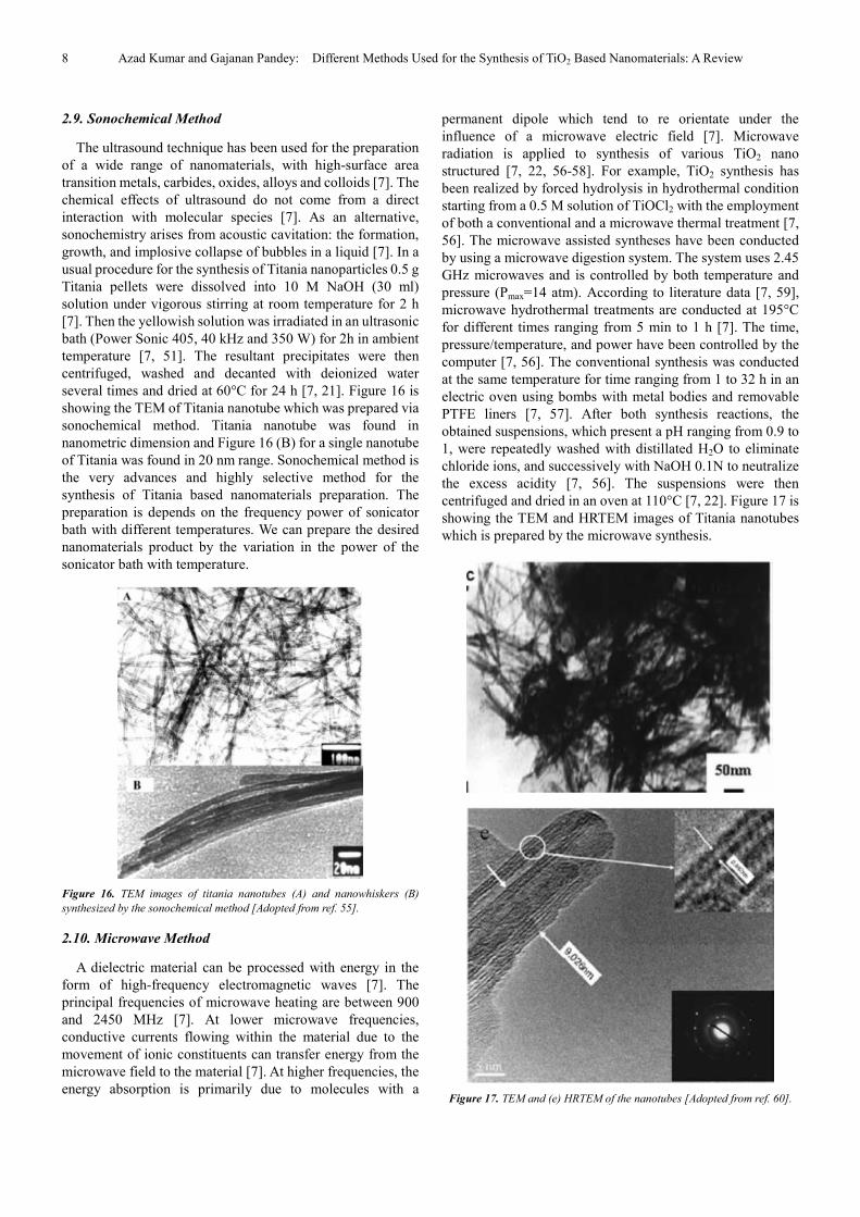
permanent dipole which tend to re orientate under the influence of a microwave electric field [7]. Microwave radiation is applied to synthesis of various TiO2 nano structured [7, 22, 56-58]. For example, TiO2 synthesis has been realized by forced hydrolysis in hydrothermal condition starting from a 0.5 M solution of TiOCl2 with the employment of both a conventional and a microwave thermal treatment [7, 56]. The microwave assisted syntheses have been conducted by using a microwave digestion system. The system uses 2.45 GHz microwaves and is controlled by both temperature and pressure (Pmax=14 atm). According to literature data [7, 59], microwave hydrothermal treatments are conducted at 195°C for different times ranging from 5 min to 1 h [7]. The time, pressure/temperature, and power have been controlled by the computer [7, 56]. The conventional synthesis was conducted at the same temperature for time ranging from 1 to 32 h in an electric oven using bombs with metal bodies and removable PTFE liners [7, 57]. After both synthesis reactions, the obtained suspensions, which present a pH ranging from 0.9 to 1, were repeatedly washed with distillated H2O to eliminate chloride ions, and successively with NaOH 0.1N to neutralize the excess acidity [7, 56]. The suspensions were then centrifuged and dried in an oven at 110°C [7, 22]. Figure 17 is showing the TEM and HRTEM images of Titania nanotubes which is prepared by the microwave synthesis.
Figure 17. TEM and (e) HRTEM of the nanotubes [Adopted from ref. 60].

American Journal of Nano Research and Applications 2018; 6(1): 1-10 9
3. Conclusion
In this paper, to study the different methods used for the synthesis of Titania and Titania based nanomaterials. There are several number of attempt have been made to synthesize TiO2 nanomaterials with different methods. In this paper, to study the effect of synthesis methods and their surface morphology with temperature. The different methods are used for the synthesis of different Titania based nanomaterials. There are various methods are used for the synthesis of titania and titania based nanomaterials such as sol-gel method, sol method, electrodeposition method, micelle and reverse micelle methods, direct oxidation, chemical vapour deposition method, hydrothermal method, solvothermal method, Ultrasonication methods and microwave method. In this paper is summarizing the synthesis methods, morphology of Titania and crystal structure of the TiO2 nanomaterials. In this paper is showing the different nanostructures of TiO2 materials.
Abbreviation
AAM: anodic alumina membrane SEM: Scanning electron microscopy TEM: transmission electron microscopy HRTEM: High Resolution transmission electron microscopy CVD: chemical vapour deposition GHz: Geega Hurtz Pmax: Maximum Pressure PTFE: Polytetrafluoroethylene XRD: X-Ray Diffraction eV: electron Volt
Acknowledgements
We thanks for financial assistance to UGC, Government of India is acknowledged. The authors also acknowledge the support provided by the Babasaheb Bhimrao Ambedkar University, Lucknow, India
References
[1] G. D. Arora, (2000), Crystallography and Crystal Structure, Ist
edition, Sarup and Sons: New Delhi, India.
[2] D. R. Askland, (1996), The Science and Engineering of Materials, Third Edition, London, Chapman & Hall, 854.
[3] R. B. Draper and F. M. Anne, Langmuir, 6, (1990) 1396-1402.
[4] A. Fujishima, (1972). "Electrochemical Photolysis of Water at a Semiconductor Electrode". Nature 238: 37.
[5] K. Pirkanniemi, M. Sillanpää (2002) Chemosphere, 48, 10, 1047-1060.
[6] M. M. Mohamed, I. Othman and R. M. Mohamed., J. of Photochemistry and Photobiology A: Chemistry, 191, (2007), 153-161.
[7] M. M. Byranvand, A. N. Kharat, L. Fatholahib, Z. M. Beiranvand, JNS 3 (2013) 1-9.
[8] https://pavemaintenance. wikispaces.com/TiO2+Photocatalys+-+Shannon.
[9] G. Meacock, K. D. A. Taylor, M. J Knowles, A. Himonides, J. Sci. Food. Agric. 73 (1997), 221-225.
[10] D. P. Macwan, P. N. Dave, J. Mater. Sci. 46 (2011) 3669–3686.
[11] O. K. Varghese, D. W. Gong, M. Paulose, K. G. Ong, E. C. Dickey, C. A. Grimes, Adv. Mater. 15 (2003) 624–627.
[12] B. M. Wen, C. Y. Liu, Y. Liu, J. Phys. Chem. B 109 (2005) 12372–12375.
[13] J. M. Wu, B. Qi, J. Phys. Chem. C. 111 (2007) 666–673.
[14] G. R. Yi, J. H. Moon, S. M. Yang, Chem. Mater. 13 (2001) 2613–2618.
[15] M. H. Bazargan, M. Malekshahi Byranvand, A. Nemati Kharat, Int. J. Mat. Res. 103 (2012) 347-351.
[16] R. K. Wahi, Y. Liu, J. C. Falkner, V. L. Colvin, J. Coll. Int. Sci. 302 (2006) 530–536.
[17] Andersson, M.; Oesterlund, L.; Ljungstroem, S.; Palmqvist, A. J. Phys. Chem. B, 106 (2002), 10674-10681.
[18] P. S. Shinde, C. H. Bhosale, J. Anal. Appl. Pyrolysis, 82 (2008) 83–88.
[19] W. H. Ryu, C. J. Park, H. S. Kwon, J. Nano. Nano. 8 (2008) 1–4.
[20] W. Tan, J. Chen, X. Zhou, J. Zhang, Y. Lin, X. Li, X. Xiao, J. Solid. State. Electrochem. 13 (2009) 651-656.
[21] H. Arami, M. Mazloumi, R. Khalifehzadeh, S. K. Sadrnezhaad, Mat. Let. 61 (2007) 4559–4561.
[22] A. B. Corradi, F. Bondioli, B. Focher, J. Am. Ceram. Soc. 88 (2005) 2639–2641.
[23] H. Nishikiori, S. Fujiwara, S. Miyagawa, N. Zettsu, K. Teshima, Applied Catalysis B: Environmental, 217, 2017, 241-246.
[24] A. L. Kretzschmar, M. Manefield, AIMS Environmental science, 2 (2), 2015, 122-133.
[25] A. k. Nishad, Bhaskarapillai, Sankaralingam Velmuruga, Journal of Hazardous Materials, 334, 2017, 160-167Padala Abdul.
[26] I. Kurajica, I. Minga, V. Grčić, M. Mandić, M. Plodinec, Materials Chemistry and Physics, 196, 2017, 194-204S.
[27] G. Scholz, E. Kemnitz, Modern Synthesis Processes and Reactivity of Fluorinated Compounds, 2017, 609-649.
[28] C. Hintze, K. Morita, R. Riedel, E. Ionescu, G. Mera, Journal of the European Ceramic Society, 36, Issue 12, 2016, 2923-2930.
[29] R. Vijayalakshmi and V. Rajendran, Archives of Applied Science Research, 2012, 4 (2): 1183-1190.
[30] M. S. AlHammad, Journal of Alloys and Compounds, 661, 2016, 251-256.
[31] R. D. Kale and Chet Ram Meena, Advances in Applied Science Research, 2012, 3 (5): 3073-3080.
[32] M. M. Chamakh, D. Ponnamma, M. A. Ali Al-Maadeed, Results in Physics, 7, 2017, 590-592.

10 Azad Kumar and Gajanan Pandey: Different Methods Used for the Synthesis of TiO2 Based Nanomaterials: A Review
[33] N. M. Makwana, C. J. Tighe, R. I. Gruar, P. F. McMillan, J. A. Darr, Materials Science in Semiconductor Processing, 42, Part 1, 2016, 131-137.
[34] Y. Zhou, Y. Huang, D. Li, W. He, Mat. Res. Bull. 48 (2013) 2420-2425.
[35] Qinghong Zhang and Lian Gao, Langmuir 2003, 19, 967-971.
[36] Hongrui Peng, Guicun Li, Zhikun Zhang, Materials Letters 59 (2005) 1142– 1145.
[37] Z. Liu, R. Wang, F. Kan and F. Jiang, Asian Journal of Chemistry; Vol. 26, No. 3 (2014), 655-659.
[38] P. Kluson, H. Luskova, O. Solcova, L. Matejova, T. Cajthaml, Materials Letters, 61, Issues 14–15, 2007, 2931-2934.
[39] S. Elbasuney, Applied Surface Science, 409, 2017, 438-447.
[40] E. Stathatos and P. Lianos, Langmuir 1997, 13, 4295-4300.
[41] Andrei Zdravkov, Juliya Kudryashova, Andrei Kanaev, Alexey Povolotskiy, et al. Materials Chemistry and Physics, 160, 2015, 73-79.
[42] S. Kurajica, I. Minga, I. Grčić, V. Mandić, M. Plodinec, Materials Chemistry and Physics, 196, 2017, 194-204.
[43] Shu Yin, Yoshinobu Fujishiro, Jihuai Wu, Minoru Aki, Tsugio Sato, Journal of Materials Processing Technology, 137, 2003, 45-48.
[44] Azad Kumar, Gajanan Pandey, Desalination and Water Treatment, 71 (2017) 406–419.
[45] K. D. Á. Sanchez, O. V. Cuchillo, A. A. Elguezabal, A. C. López, A. H. Gómez, Mater. Chem. Phys., 13 (2013) 423-430.
[46] C. Albano, Y. Sarmiento, G. González, Mat. Res. Bull.321 (2012) 76-79.
[47] Wu, J. M. J. Cryst. Growth. 269 (2004) 347-352.
[48] Wu, J. M.; Zhang, T. W.; Zeng, Y. W.; Hayakawa, S.; Tsuru, K.; Osaka, A. Langmuir. 21 (2005) 6995-6999.
[49] I. Djerdj, A. M. Tonej, M. Bijelic, V. Vranesa, A. Turkovic, Vacuum. 80 (2005) 371-378.
[50] J. H. Lee, H. S. Choi, J. H. Lee, Y. J. Kim, S. J. Suh, C. S. Chi, H. J. Oh, J. Cryst. Growth. 311 (2009) 638-641.
[51] Wu, J. M.; Hayakawa, S.; Tsuru, K.; Osaka, A. Cryst. Growth Des. 2 (2002) 147-152.
[52] John C. Hulteen and Charles R. Martin, J. Mater. Chem., 1997, 7 (7), 1075–1087.
[53] U. M. Patil, S. B. Kulkarni, P. R. Deshmukh, R. R. Salunkhe, C. D. Lokhande, Journal of Alloys and Compounds. 509 (2011) 6196-6199.
[54] J. Liu, J. Xu, R. Che, H. Chen, M. Liu, Z. Liu, Chem – A. Eur. J. 19 (2013) 6746-6752.
[55] Zhu, Y.; Li, H.; Koltypin, Y.; Hacohen, Y. R.; Gedanken, A. Chem. Commun. 12 (2001) 2616-2621.
[56] P. A. Russo, S. Lima, V. Rebuttini, M. Pillinger, M. G. Willinger, N. Pinna, A. A. Valente, RSC Adv. 3 (2013) 2595-2603.
[57] Barnard, A. S.; Zapol, P. Phys. ReV. B, 70 (2004) 235-241.
[58] A. Kruth, S. Hansen, T. Beweries, V. Brüser, K.-D. Weltmann, ChemSusChem. 6 (2013) 152-159.
[59] S. Komarneni, R. K. Rajha, and H. Katsuki, Mat. Chem. Phys. 61 (1999) 50–54.
[60] Xing Wua, Qi-Zhong Jianga, Zi-Feng Maa, Min Fua, Wen-Feng Shangguan, Solid State Communications 136 (2005) 513–517.


![High Responsivity Ultraviolet Photoconductors Based on ...article.ajnano.org/pdf/10.11648.j.nano.20190701.12.pdf · devices in the ultraviolet (UV) range [5, 6]. ZnO is isomorphic](https://img.pdfslide.us/doc/110x75/5f0300a67e708231d4070e70/high-responsivity-ultraviolet-photoconductors-based-on-devices-in-the-ultraviolet.jpg)


![The Crystallization Kinetics, Structural and Magnetic ...article.ajnano.org/pdf/10.11648.j.nano.20180603.11.pdf · Hitachi Metals Ltd. [1]. The Cu additives play a key role in the](https://img.pdfslide.us/doc/110x75/5e967ff7db60f511073fe53e/the-crystallization-kinetics-structural-and-magnetic-hitachi-metals-ltd-1.jpg)