Embed Size (px)
Citation preview

Differences in the Facility Design,Europe & Asian Developing Countries

Presentation Contents
Facility design differences between Europe and Asian developing countries will be discussed based on some examples:
– Personnel / material air lock design
– Clean room floor construction options
– UAF areas for autoclave unloading
– Design of aseptic filling facilities (room arrangements, RABS / isolator design)
– Design of exhaust HEPA filter housings
– Design of technical areas
– Project schedule / realization time
For questions marked in red, the audience is invited to provide answers and suggestions 2

Personnel Air Lock Design
Regulatory requirements:
– Required to separate different areas (e.g. different clean room grades, bio-positive & bio-negative areas, etc.)
– Different clean room grades must be cascaded
– Door interlock
– Furniture requirements: Hand wash sinks, hand disinfection, mirror, locker cabinets, etc.
– Step-over bench (for shoes change) to divide rooms into a «clean» and «less clean» side
3

Personnel Air Lock Design
Typical design example found in Asian facilities:
4

Personnel Air Lock Design
Typical design example found in Asian facilities:
– Room grades are cascaded: CNC => D => C
– One room to take off the CNC garments, one room to don the grade C garments
– One clean room grade per room
=> The big question: Where shall the step-over bench be placed…?
5

Personnel Air Lock Design
Position of the step-over bench:
6
Option 1 Option 2
Or Option 1 and Option 2...?
Which is the best solution, and why...? Suggestions...?

Personnel Air Lock Design
Problems with placing the step-over bench:
– According to the guidelines, a step-over bench (shoes change) should be used to separate the clean area from the less clean area
– However, the requirements for grade D or C are strictly defined, there is e.g. no “grade C less clean” classification
– Since the shoes should be changed while crossing the step-over bench, the following problems exist with option 1 and/or option 2 on the slide before:
=> Surface contamination (bioburden) is transferred via the shoes from CNC to D and from D to C
Suggestions to solve this problem…?7

Personnel Air Lock Design
Typical design example found in European facilities:
8

Personnel Air Lock Design
Typical design example found in European facilities:
– Room grades are cascaded (CNC => D => C), but in one common PAL room
– The PAL room is separated into a D side (less clean) and a C side (clean) by the step-over bench
– CNC garments are left on the D side, C garments are donned on the C side
=> How can one room be classified with 2 different clean room grades...?
9

Personnel Air Lock Design
Typical design example found in European facilities, monitoring limits:
10
D Side C Side
Air quality, particles Grade C limits Grade C limits
Air quality, microbio. contamination
Grade C limits Grade C limits
Surface cleanliness, microbio. contamin.
Grade D limits Grade C limits
To achieve a grade C air quality in the whole room, also on the D side, is relatively easy. This mainly depends on the kind of HEPA filter used, the air change rate and the pressure cascade

Personnel Air Lock Design
Keeping grade C air quality on the D side:
11
Personnel Air Lock Design
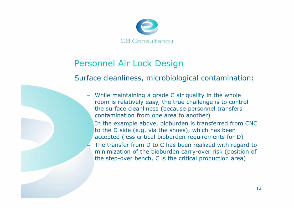
Surface cleanliness, microbiological contamination:
– While maintaining a grade C air quality in the whole room is relatively easy, the true challenge is to control the surface cleanliness (because personnel transfers contamination from one area to another)
– In the example above, bioburden is transferred from CNC to the D side (e.g. via the shoes), which has been accepted (less critical bioburden requirements for D)
– The transfer from D to C has been realized with regard to minimization of the bioburden carry-over risk (position of the step-over bench, C is the critical production area)
12

Personnel Air Lock Design
Locker cabinets connected to the exhaust air, for smelly shoes or wet clothes:
13

Material Air Lock Design
Typical examples found in Asian facilities for transfers from CNC to C:
14
What are the advantages...
...and disadvantages of these design
options?

Material Air Lock Design
Problems with example 1, CNC => D => C:
15
Personnel
not allowed
Personnel
not allowed
Material Air Lock Design
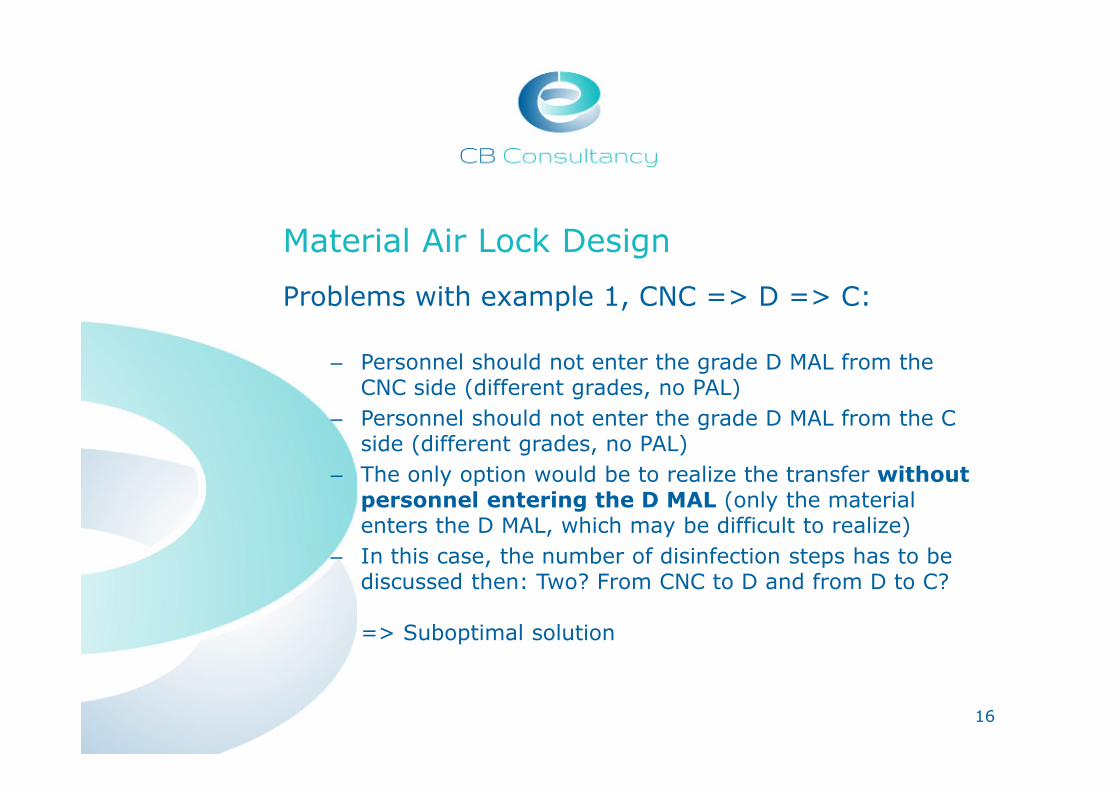
Problems with example 1, CNC => D => C:
– Personnel should not enter the grade D MAL from the CNC side (different grades, no PAL)
– Personnel should not enter the grade D MAL from the C side (different grades, no PAL)
– The only option would be to realize the transfer without personnel entering the D MAL (only the material enters the D MAL, which may be difficult to realize)
– In this case, the number of disinfection steps has to be discussed then: Two? From CNC to D and from D to C?
=> Suboptimal solution
16

Material Air Lock Design
Problems with example 2, CNC => CNC => C:
17
Personnel
not allowed
Personnel
allowed

Material Air Lock Design
Problems with example 2, CNC => CNC => C:
– Personnel should not enter the grade C MAL from the CNC side (different grades, no PAL) => material has to be loaded / unloaded from the MAL without personnel entering the MAL
– Personnel can enter the grade C MAL from the C area to load / unload material
– The need for a buffer room should be questioned, because it has the same classification as the rest of the CNC area (which is even no formal clean room grade)
– The buffer room does not contribute to the prevention of contamination carry-over, only complicates the material transfer procedure
=> Better, but still suboptimal solution 18

Material Air Lock Design
Optimized solution CNC => C in one MAL:
19
Mat-erial
Mat-erial
disinfection transfer

Material Air Lock Design
Optimized solution CNC => C in one MAL:
– Again, to achieve grade C limits (particles and bioburden) for the air in the MAL is not a problem. This mainly depends on the HEPA filter used, air change rate and the interlock time for air flushing
– The true challenge is again to control the bioburden on the surfaces
– An adequate disinfection procedure is needed for material transfers from CNC to C
– For critical transfers (e.g. CNC directly to B, or materials with complicated surfaces which are hard to disinfect manually), e.g. VHP fumigation should be considered
20

Material Air Lock Design
MAL sizes for material transfer:
– Generally, the smallest possible MAL size is the best => minimization of the contamination carry-over risk
– The risk is lowest for e.g. a small pass-through box because in such a box, all the inner surfaces can be disinfected easily as well
21
Clean Room Construction
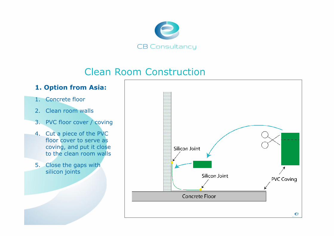
1. Option from Asia:
1. Concrete floor
2. Clean room walls
3. PVC floor cover / coving
4. Cut a piece of the PVC floor cover to serve as coving, and put it close to the clean room walls
5. Close the gaps with silicon joints

Clean Room Construction
Why is this option suboptimal?
23
1. No chamfer (support below the coving)
2. Not really easy to clean because of irregularities
3. Easy to damage
4. Complicated construction
5. Floor cover is not continuous

Clean Room Construction – Examples Option 1
24

Clean Room Construction
2. Option from Asia:
1. Concrete floor
2. Clean room walls
3. PVC coving � one piece
overlapping the clean room wall (the floor cover directly covers a part of the wall panels)
4. Close the gaps with silicon joint

Clean Room Construction
Why is this option suboptimal?
Less worse than option 1 because the floor and coving is one piece, but…
1. No chamfer (support below the coving)
2. May not be easy to clean because of irregularities
3. Easy to damage (no support below coving)
4. Difficult corner construction
5. Floor cover is not continuous
26

Clean Room Construction – Examples Option 2
27

Clean Room Construction
3. Option from EU:
1. Concrete floor
2. Epoxy floor
3. Install U-profile for clean room walls
4. Fix clean room walls into U-profile
5. Put silicon joint between wall and floor
6. Fix chamfer onto silicon joint
7. PVC coving for covering chamfer
8. Close the gaps with silicon joint

Clean Room Construction
Better because…
• Stability of the construction, chamfer (support) below the coving
• Continuous floor cover in one piece
• Can be cleaned / decontaminated / disinfected to a high degree
But…
• Complex installation
29

Clean Room Construction – Examples Option 3
30

Clean Room Construction
4. Option from EU:
1. Concrete floor
2. Epoxy floor
3. Install U-profile for clean room walls
4. Fix clean room walls into U-profile
5. Put silicon joint between the U-profile and the floor, and between the U-profile and the wall panel

Clean Room Construction
The best option because…
• Simple construction
• Easy to clean as well, although there is no coving
• Air-tight to a high degree if silicone joints are made properly
• Continuous floor cover in one piece
• Modification of the clean room structure (repositioning of walls) is relatively easy
32

Clean Room Construction – Examples Option 4, Walls and Windows
13

Clean Room Construction – Examples Option 4, Stainless Steel Wall Panels
13
Clean Room Construction – Examples Option 4, Glass Wall Panels
13

UAF for Autoclave Unloading
Situation sometimes found in Asian facilities:
36
What is the purpose of the grade C UAF area…?
(or similarly, unloading in B / B UAF)

UAF for Autoclave Unloading
Purpose of the UAF for autoclave unloading:
– Is the UAF used to handle sterile goods openly (e.g. assembling operations or closing of bottles)?
– Is a grade C UAF suitable to handle sterile goods (aseptically)?
– Problem: If sterile goods really must be handled aseptically, an A in B area would be required. This area might be quite large to unload an autoclave, with operators having to walk into this area, which should not be the case for grade A
– Better solution: Prepare the goods to be sterilized in a way that they will remain sterile if unloaded into a standard clean room (without UAF)
37

UAF for Autoclave Unloading
Examples for proper preparation of goods for sterilization:
38
Packing and sealing of goods in steam-permeable bags
Pre-assembling with vent filters which are
gas-permeable

Design of Filling Lines (Grade A/B)
Typical design found in Asian facilities:
– One independent clean room compartment per filling line (with dedicated airlocks, corridor, washing area, etc.)
– Each process step (e.g. vial washing / sterilization, filling, capping) is performed in a separate room
– Different environment (clean room grade) for different process steps
39

Design of Filling Lines (Grade A/B), Layout Example Asia
40
Lyo-Line, Grade A/B Design, 5 Rooms
Each process step has its own room with different clean room grades
� Designed in this way a large area / many rooms are needed
� More complex material, product and personnel flows result
Grade C
Grade D
Grade B
Grade CNC
Room No. Process Grade
1 Washing / Steri. D
2 Filling A/B
3 Capping B
4 Vials out CNC
5 Lyo technic Black
Grade A

Design of Filling Lines (Grade A/B), Layout Example Asia
41
Syringe Filling Line,A/B Design, 4 Rooms
Same points as mentioned above apply
Grade C Grade DGrade B Grade CNC
Room No.
Process Grade
1 Loading CNC
2 Bag removal
C
3 Filling A/B
4 Syringes out
CNC
Grade A
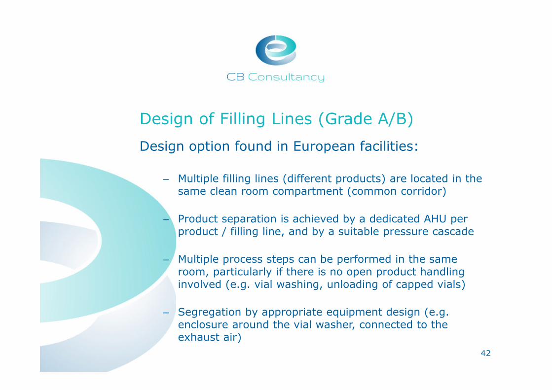
Design of Filling Lines (Grade A/B)
Design option found in European facilities:
– Multiple filling lines (different products) are located in the same clean room compartment (common corridor)
– Product separation is achieved by a dedicated AHU per product / filling line, and by a suitable pressure cascade
– Multiple process steps can be performed in the same room, particularly if there is no open product handling involved (e.g. vial washing, unloading of capped vials)
– Segregation by appropriate equipment design (e.g. enclosure around the vial washer, connected to the exhaust air)
42

Design of Filling Lines (Grade A/B), Layout Example EU
43
Syringe- & Lyo-Line,A/B Design, in the same clean room compartment
Syringe Filling LineVial Filling Line / Lyo Grade A Grade B Grade C
Room No.
Process Grade
1 Loading, Washing, vials/syringes out (shared)
C
2 Filling syringes (dedicated)
A/B
3 Filling vials (dedicated)
A/B
4 Lyophilization(dedicated)
A/B
Connected by one corridor

RABS vs. Isolator
Different options exist to design the environment / enclosure for aseptic filling processes. The most used ones are:
– Grade A in B, open, air flow guided with e.g. curtains (not state-of-the-art anymore)
– Restricted access barrier system (RABS), open, passive
– RABS, open, active
– RABS, closed, active
– Isolator enclosure
Open RAB systems are currently found in a lot of Asian facilities, and are most likely the preferred option in Asia (currently)
44

RABS vs. Isolator
45
Open RABS Isolator

RABS vs. Isolator
Open processing, grade A in B, filling line placed in a clean room:
46
� Air flow guided by curtains around the filling line
� ISO No. reflect the state «in operation»
� Curtains can be opened at any position for interventions
� Not state-of-the-art anymore, limited product protection only

RABS vs. Isolator
Open, passive RABS:
47
� The filling line is enclosed by rigid cladding (RABS)
� Interventions only possible via glove ports
� Air is provided to the grade A area via the AHU / FFUs installed as part of the clean room (passive RABS)
� Air recirculates via the grade B clean room (open RABS)

RABS vs. Isolator
Open, active RABS:
48
� The filling line is enclosed by rigid cladding (RABS)
� Interventions only possible via glove ports
� Air for the grade A area is provided by a dedicated AHU / FFUs (active RABS)
� Air recirculates from the grade A area via the grade B clean room (open RABS)

RABS vs. Isolator
Closed, active RABS:
49
� The filling line is enclosed by rigid cladding (RABS)
� Interventions only possible via glove ports
� Air for the grade A area is provided by a dedicated AHU / FFUs (active RABS)
� Air recirculates from the grade A area via dedicated ducts (closed RABS)

RABS vs. Isolator
Isolator:
50
� The filling line is enclosed by rigid cladding, sealable for fumigation
� Interventions only possible via glove ports
� Air for the grade A area is provided by a dedicated AHU / FFUs
� Internal air recirculation
� Lower requirements for the surrounding clean room (ISO 8, C in operation, or no requirement, D)

RABS vs. Isolator
Closed RABS / Isolator:
– A closed RABS is already quite similar to an isolator in terms of the line enclosure, the required AHU, investment costs, etc.
– However, a closed RABS does not provide the critical advantage of an isolator which can be operated in a grade D or C room
– Thus, the trend is that western companies go for isolator solutions for new filling line projects
51

RABS vs. Isolator
Comparison of main features:
52
Feature A in B oRABS cRABS Isolator
Product protection (sterility) Basic Better Best Best
Operator protection (e.g. biosafety)
No, open No, open Good Best
Negative pressure operation No No No Possible
Interventions DirectGlove ports
Glove ports
Glove ports
Environment for enclosure B B B min. D
Opening of the enclosure during processing
Allowed Allowed AllowedNot
allowed*
*e.g. alpha / beta ports or VHP ALs to be used for all transfers
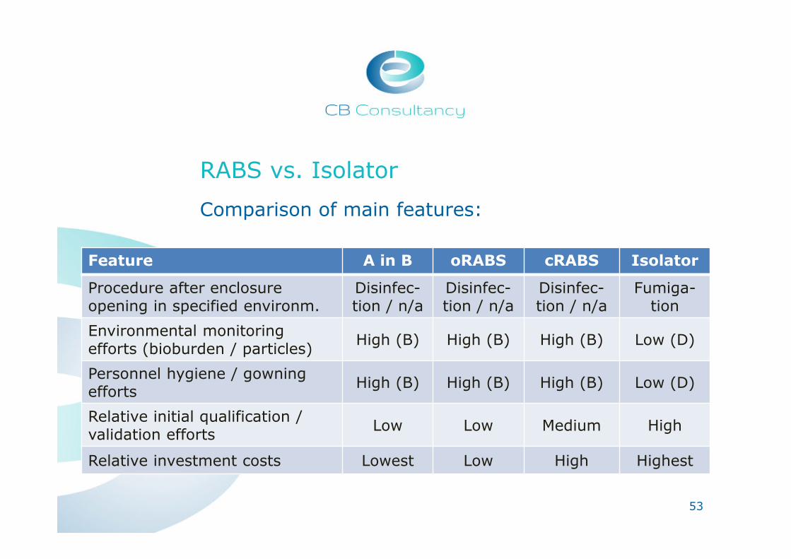
RABS vs. Isolator
Comparison of main features:
53
Feature A in B oRABS cRABS Isolator
Procedure after enclosure opening in specified environm.
Disinfec-tion / n/a
Disinfec-tion / n/a
Disinfec-tion / n/a
Fumiga-tion
Environmental monitoring efforts (bioburden / particles)
High (B) High (B) High (B) Low (D)
Personnel hygiene / gowning efforts
High (B) High (B) High (B) Low (D)
Relative initial qualification / validation efforts
Low Low Medium High
Relative investment costs Lowest Low High Highest

RABS vs. Isolator, Layout Example Asia
Vial Filling Line, RABS, 4 RoomsEach process step has its own room with different clean room grades
� Optimization potential for space, energy (air exchange rate) and
gowning/degowning between the different rooms
� Machine has to match perfectly with the walls (installation challenge)
� Higher monitoring frequencies (grade B has to be monitored each day)
� Cheaper equipment 54
Grade C
Grade D
Grade B
Grade CNC
Room No.
Process Grade
1 Washing / Steri. D
2 Filling A/B
3 Capping B
4 Vials out CNC
Grade A

RABS vs. Isolator, Layout Example EU
Vial Filling Line, Isolator, 1 Room
The room includes a filling line with an isolator.
� Space, gowning efforts and energy saving �optimized option
� Easier installation (machine does not penetrate walls)
� Lower monitoring frequencies
� More expensive equipment
…but the investment in an isolator is worth it because of the easy handling of the overall filling process.
55
- Vial Washing / Steri.
- Vial Filling
- Capping
Room No.
Process Grade
1Washing / Sterilization, Filling, Capping
C, A isolator

RABS vs. Isolator, Layout Example Asia
56
Lyo-Line, RABS, 6 Rooms
Each process step has its own room with different clean room grade.
� Same points than described before
� Lyos need an extra separate room for the technique
- Vial Washing / Steri.
- Vial Filling
- Lyophilisation
- Capping Grade C
Grade DGrade B
Grade CNC
Room No.
Process Grade
1 Vials In CNC
2 Washing / Steri. D
3 Filling / Lyo A/B
4 Capping C
5 Vials out CNC
6 Lyo technic BlackGrade A

RABS vs. Isolator, Layout Example EU
Lyo-Line, Isolator, 3 Rooms
� Technique of lyos is accessible from the intermediate ceiling
� Lyos and technical area go over multiple levels
57
- Vial Washing / Steri.
- Vial Filling
- Lyophilisation- Vial Feeding & Testing
- Capping
Room No.
Process Grade
1 Vials Feeding D
2
Washing / Sterilization, Filling, Lyophilisation, Capping,
C, A isolator
3 Vials out CNC
Grade CGrade A Grade D Grade CNC

RABS vs. Isolator, Layout Example EU
58
Lyo-Line, Isolator, 2 Rooms
� The lyos have its own technical area which is accessible from the black area for maintenance
- Vial Washing / Steri.
- Vial Filling
- Lyophilisation
- Capping
Grade A Grade C Black
Room No.
Process Grade
1 Loading, Washing / Sterilization, Filling, Lyophilisation,Capping
C, A isolator
2 Lyo technic Black

Terminal exhaust HEPA Filter Housings
Situation:
– Exhaust HEPA filters in production rooms are e.g. required in OSD facilities (for highly active APIs) or in some biosafety relevant facilities
– Exhaust HEPA filters have to be tested regularly for integrity (similar to the requalification of clean room supply air HEPA filters)
– This requires a special design for exhaust HEPA filter housings
– We found that Asian manufacturers are sometimes unaware of this situation / requirement
=> How are exhaust HEPA filters tested, while they are mounted in the housing?
59

Terminal exhaust HEPA Filter Housings
Integrity testing for terminal exhaust filters:
– The testing procedure is similar to e.g. the DOP or DEHS test for supply air HEPA filters
– Raw gas, containing aerosol particles, is applied from the clean room side
– Clean gas has to be sampled downstream of the HEPA filter, i.e. in the housing or exhaust duct
– The particles are counted in both, the raw and clean gas
– The leakage or retention rate for particles is calculated
60

Terminal exhaust HEPA Filter Housings
Simple example for an exhaust filter housing:
61
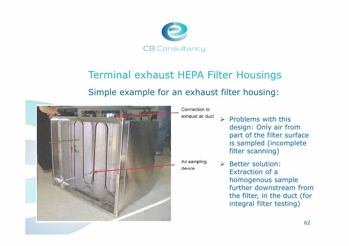
Terminal exhaust HEPA Filter Housings
Simple example for an exhaust filter housing:
62
� Problems with this design: Only air from part of the filter surface is sampled (incomplete filter scanning)
� Better solution: Extraction of a homogenous sample further downstream from the filter, in the duct (for integral filter testing)

Terminal exhaust HEPA Filter Housings
Hi-tech example for an exhaust filter housing:
63

Technical Area & HVAC Design
Preferred design in Europe, technical level on top, section view:
64

Technical Area & HVAC Design
Preferred design in Europe, technical level on top, top view:
65

Technical Area & HVAC Design
Preferred design in Europe, technical level on top, advantages:
– Optimized duct routing, ductwork minimized in length
– AHU and all other components requiring maintenance / calibration (sensors, CVC / VVC, dampers, etc.) are installed close together, on the same level => efficient installation, minimization of wiring, etc.
– Easy access because there is a full dedicated building level for HVAC installations
– For makeup air and exhaust air in the example above: Partial redundancy allows for continuous operation during maintenance
66

Technical Area & HVAC Design
Alternative found in Asia, technical area on the side, top view:
67

Technical Area & HVAC Design
Alternative found in Asia, technical area on the side, section view:
68

Technical Area & HVAC Design
Alternative found in Asia, technical area on the side, features:
– Longer ductwork system compared with the other option presented
– Components requiring maintenance / calibration (sensors, CVC / VVC, dampers, etc.) should be installed along a catwalk for easy access, and to minimize walking on the clean room ceiling
– The AHU and field elements for control are distributed within a larger area => more wiring, etc. is required accordingly
69

Technical Area & HVAC Design
If there is no space / not enough height for a mezzanine / catwalk (not recommended):
– All components requiring maintenance / calibration (sensors, CVC / VVC, dampers, etc.) should be installed in the technical area, before the ducts “vanish” above the clean room ceiling
– Thus, the ducts leading to individual rooms must be separated in the technical area already, making the ductwork even longer
70

Project Schedule and Realization
Comparison of the time required for planning and realization of a project:
– On the following slide, 2 project schedules have been compared
– One project was realized in Europe, the other in Asia
– Both projects are similar (installation of a filling line, including clean rooms, HVAC, etc.)
71

Which Time Schedule belongs to which Continent?
72
Example of an EU Time Schedule
Example of an Asian Time Schedule

Difference in Time Schedule
• Generally the time for the same project phase is shorter in Asia than in EU (not always an advantage)
• EU: higher time investment in quality control and therefore less investments later for error corrections
• Asia: basis of design and detail design overlap �
could lead to misunderstandings later
• Construction phase is the most similar one regarding duration
• Also qualification takes longer in the EU, due to a thorough and detailed testing
• Long leadtime-equipment should be ordered as early as possible to avoid delays
73
Why does this time difference appear?

74
Further Questions?