Embed Size (px)
Citation preview

R
R
R
R
R
R
R
R
R
R
R
R
R
R
R
R
PX771A
Differential Pressure Transmitter
Operator's ManualM-3602/1101Operator's ManualM-3602/1101ME
R
An OMEGA Technologies CompanyAn OMEGA Technologies Company

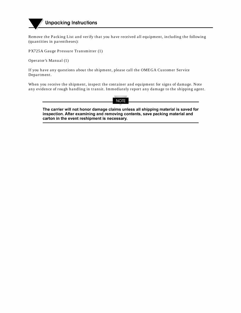
Remove the Packing List and verify that you have received all equipment, including the following(quantities in parentheses):
PX725A Gauge Pressure Transmitter (1)
Operator’s Manual (1)
If you have any questions about the shipment, please call the OMEGA Customer ServiceDepartment.
When you receive the shipment, inspect the container and equipment for signs of damage. Noteany evidence of rough handling in transit. Immediately report any damage to the shipping agent.
M-3602 Contents / 0 - 1
M-3602
DIFFERENTIAL PRESSURE TRANSMITTERS - SERIES PX771A
TABLE OF CONTENTS
SECTION TITLE PAGE #
Section 1 - INTRODUCTION
1.1 PRODUCT DESCRIPTION............................................................................................1-11.2 TRANSMITTER FEATURES.........................................................................................1-11.3 MODELS APPROVED FOR HAZARDOUS AREAS ...................................................1-21.4 USING THIS MANUAL .................................................................................................1-3
Section 1A – DIFFERENTIAL PRESSURE TRANSMITTERS Series PX771A
1A.1 PRODUCT DESCRIPTION......................................................................................... 1A-11A.2 THEORY OF OPERATION......................................................................................... 1A-11A.3 IDENTIFYING TRANSMITTER OPTIONS.............................................................. 1A-31A.4 TRANSMITTER MOUNTING .................................................................................... 1A-7
Standard Process Flange ............................................................................................. 1A-7Optional Process Manifold Block ................................................................................ 1A-8Vent Plug ......................................................................................................................1A-8
1A.4.1 Transmitter Housing Rotation.................................................................................... 1A-81A.5 DP MEASUREMENT APPLICATIONS................................................................... 1A-10
Liquid Application...................................................................................................... 1A-10Gas Application .......................................................................................................... 1A-10Steam Application...................................................................................................... 1A-11Liquid Level Application ........................................................................................... 1A-12
1A.6 SERVICE CHECKS................................................................................................... 1A-131A.7 TRANSMITTER SPECIFICATIONS........................................................................ 1A-14
Section 2 - INSTALLATION
2.1 INSTALLATION NOTES...............................................................................................2-12.2 INSTALLATION IN HAZARDOUS AREAS.................................................................2-12.3 ELECTRICAL WIRING NOTES ...................................................................................2-22.4 WIRING OF 4-20mA SIGNAL/POWER LOOP.............................................................2-32.5 WIRING OF 1-5V SIGNAL/POWER LOOP..................................................................2-62.6 EFFECTS OF LEAD & LOAD RESISTANCE & SUPPLY VOLTAGE.......................2-6
Section 3 - CALIBRATION
3.1 CALIBRATION SETUP..................................................................................................3-13.2 ACCESS TO ADJUSTMENTS.......................................................................................3-13.3 EXTERNAL CHECK PROCEDURE .............................................................................3-43.4 CALIBRATION ADJUSTMENTS .................................................................................3-43.5 TYPES OF RANGE CALIBRATION .............................................................................3-53.6 ZERO-BASED CALIBRATION......................................................................................3-83.7 ELEVATED ZERO CALIBRATION ..............................................................................3-83.7.1 Zero Elevation Example .................................................................................................3-93.8 SUPPRESSED ZERO CALIBRATION..........................................................................3-93.8.1 Zero Suppression Example...........................................................................................3-113.9 SELECTABLE DAMPING ...........................................................................................3-11
0 - 2 / Contents M-3602
M-3602
DIFFERENTIAL PRESSURE TRANSMITTERS - SERIES PX771A
TABLE OF CONTENTS
SECTION TITLE PAGE #
Section 4 - SERVICE
4.1 GENERAL .......................................................................................................................4-14.2 TROUBLESHOOTING...................................................................................................4-14.3 FACTORY REPAIRS ......................................................................................................4-1
Section 5 - SPECIFICATIONS
5.1 FUNCTIONAL SPECIFICATIONS...............................................................................5-1Current Loop Mode: .................................................................................................5-1Voltage Mode: ...........................................................................................................5-1Calibration Adjustments:.........................................................................................5-1Response Time & Damping......................................................................................5-1Linearity:...................................................................................................................5-2
5.2 PERFORMANCE SPECIFICATION.............................................................................5-2Accuracy: ...................................................................................................................5-2Resolution: ................................................................................................................5-2Long Term Stability: ................................................................................................5-2Ambient Temperature Effect: ..................................................................................5-2Power Supply Effect: ................................................................................................5-2Ripple and Noise:......................................................................................................5-2
5.3 ENVIRONMENTAL SPECIFICATION ........................................................................5-2 Temperature Limits: ................................................................................................5-2 Humidity Limits: ......................................................................................................5-3
EMI Effect:................................................................................................................5-3Surge Protection: ......................................................................................................5-3Vibration Effect: .......................................................................................................5-3
5.4 PHYSICAL SPECIFICATIONS .....................................................................................5-3Fill Media: .................................................................................................................5-3Electrical Housing: ...................................................................................................5-3Electrical Connections:.............................................................................................5-3
APPENDICES
Class I, Division 2 Hazardous Locations .................................................................................. Appendix ALoop Powered Indicator Option ................................................................................................ Appendix BMaterial Safety Data Sheets ......................................................................................................Appendix Z
M-3602 Introduction / 1-1
Section 1INTRODUCTION
1.1 PRODUCT DESCRIPTION
Series PX771A Differential Pressure Transmitters convert pressure measurements into aproportional 4-20 mA or a 1 - 5 Vdc output signal that functions as the input to a controller,recorder, indicator or similar device. These transmitters find application in the gas, water,and process industries that require accurate measurements over a wide range ofenvironmental conditions.
1.2 TRANSMITTER FEATURES
The features that follow are common to all transmitter models are described in the followinglisting:.
Pressure Sensor. Strain gauge, piezo-resistive sensors perform pressuremeasurements.
Signal-Power Loop. The transmitter requires a nominal 24 Vdc power source tooperate the signal loop, a 2-wire 4-20 mA output.
Available Voltage Output. For low power applications, a 1-5 Vdc output is userconfigurable via an internal jumper.
Adjustable Ranges. Transmitters are provided with coarse switch and fine potadjustments for range calibration. Span is adjustable from 16 to 100% of the upper rangelimit, while zero is adjustable from -600 to 600% of the lower range limit for elevationand suppression.
Damping. A circuit jumper selects damping periods of .275 sec or 1 ms to control trans-mitter response to a change of the measured variable.
Mechanical Assembly. The transmitter electronics enclosure is constructed of castaluminum with an epoxy finish. The materials offered for diaphragms, processconnections, flanges, bolts, etc. are given in Section 1A.
Fill System. The transmitter's diaphragm and sensor operate in a sealed fluid system.These systems are furnished with DC 200 as the fill fluid.
Electrical Conduit Port. Two 1/2 inch NPT female ports are provided for electricalconduit.
1-2 / Introduction M-3602
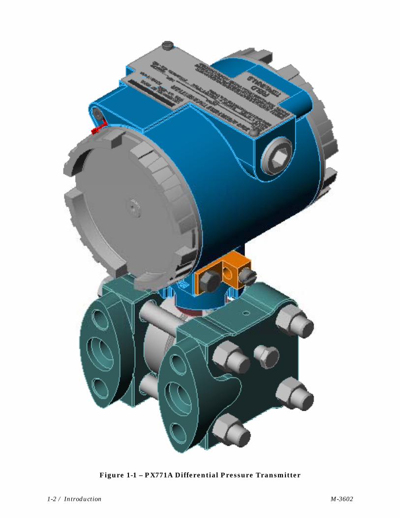
Figure 1-1 – PX771A Differential Pressure Transmitter
M-3602 Introduction / 1-3
1.3 MODELS APPROVED FOR HAZARDOUS AREAS
Transmitter models certified for operation in hazardous areas by Underwriters Laboratories(UL) will have the appropriate logo inscribed on the instrument data plate. These modelsare intended for use in the following hazardous locations:
Explosion-proof for Class I, Division 1, Groups C and D.
Nonincendive for Class I, Division 2, Groups A, B, C and D.
The National Electric Code, Article 500, defines the above classes and divisions as follows:
Class I Atmospheres: Contains flammable gases or vapors.
Class II Atmospheres: Contains combustible dust particles.
Class III Atmospheres: Contains ignitable fibers or flyings.
Division 1:Where continuous exposure, or threat of fire or explosion may be present due to accident oruncommon occurrence.
Division 2:Where threat of fire or explosion is not normally present, and not likely to result fromabnormal occurrence.
Groups A through D:Cover various flammable gases and liquids such as ethyl- ether vapor, gasoline, acetone,etc.
Groups E through G:Cover various combustible dusts such as dust from metalworking, coal, coke carbon black,grain, etc.
1.4 USING THIS MANUAL
Section 1A provides information relevant to product description, types of mounting,measurement applications, service checks, and specifications.
Sections 2 through 5 describe installation, calibration, service and general specifications.The Loop Powered Indicator option is covered in Appendix B.
M3602 DP Transmitters / 1A-1
Section 1ADIFFERENTIAL PRESSURE TRANSMITTERS
Series PX771A
1A.1 PRODUCT DESCRIPTION
The Series PX771A Differential Pressure (DP) Transmitter measures the pressuredifferential existing across an orifice plate or similar type device and converts it into aproportional 4-20 mA or a 1-5 Vdc signal that can be applied to the input of a device such asa flow computer, controller, recorder, etc. This transmitter is typically used with gas, waterand chemical processes to provide accurate measurements under extreme environmentalconditions.
The DP transmitter is offered in ranges from 0-100 inH2O to 0-300 psi. A listing of rangesfor the Series PX771A is given in Table 1A-A.
The transmitter can be installed on a DP pressure manifold or it may be specified with auniversal mounting bracket. The bracket permits the unit to be clamped to a two-inch pipeor secured to a support structure.
The transmitter electronics enclosure is constructed of cast aluminum. The diaphragm,flanges, flange bolts and the manifold are offered in two materials; stainless steel, andHasteloy C.
1A.2 THEORY OF OPERATION
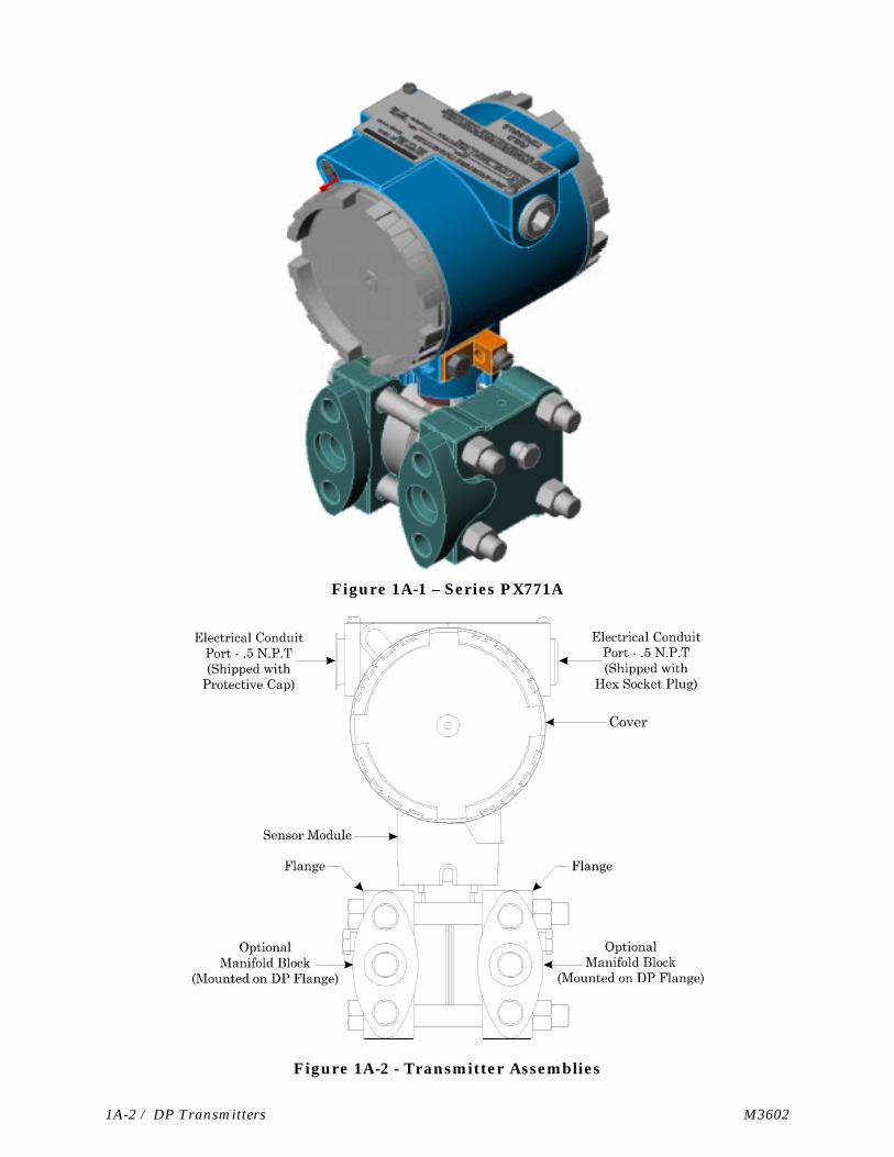
The main assemblies of the DP transmitter are the electronics housing, sensor module andprocess flanges as noted in Figure 1A-2. The electronics housing encloses the amplifierboard and the field wiring terminals as shown in the schematic of Figure 1A-3. The sensormodule contains the pressure sensor, two sealed fluid systems, an overpressure diaphragm,and two isolation diaphragms. The flanges provide the HI and LO port connections and alsofunction as the outer wall of the pressure input chambers.
The electronic pressure sensor located at the upper part of the sensor module is mounted ona micro diaphragm that serves as a divider between the two fluid systems. One fluid systemcorresponds to the HI pressure input, and the other to the LO pressure input. The isolationdiaphragm of each system isolates the fluid system from the input pressure.
When a differential pressure is applied across the HI and LO ports, both isolationdiaphragms will compress or retract in response to the change of differential. The movementof these diaphragms causes similar pressure changes in each of the sealed fluid systemsthat are detected by the sensor.
If the differential pressure applied to the HI-LO ports accidentally exceeds the upper limitsof the transmitter, an overpressure diaphragm mechanism takes control of the situation.The action of this mechanism prevents the overpressure from reaching the sensor, therebyminimizing the risk of damage.
1A-2 / DP Transmitters M3602
Figure 1A-1 – Series PX771A
Figure 1A-2 - Transmitter Assemblies
M3602 DP Transmitters / 1A-3
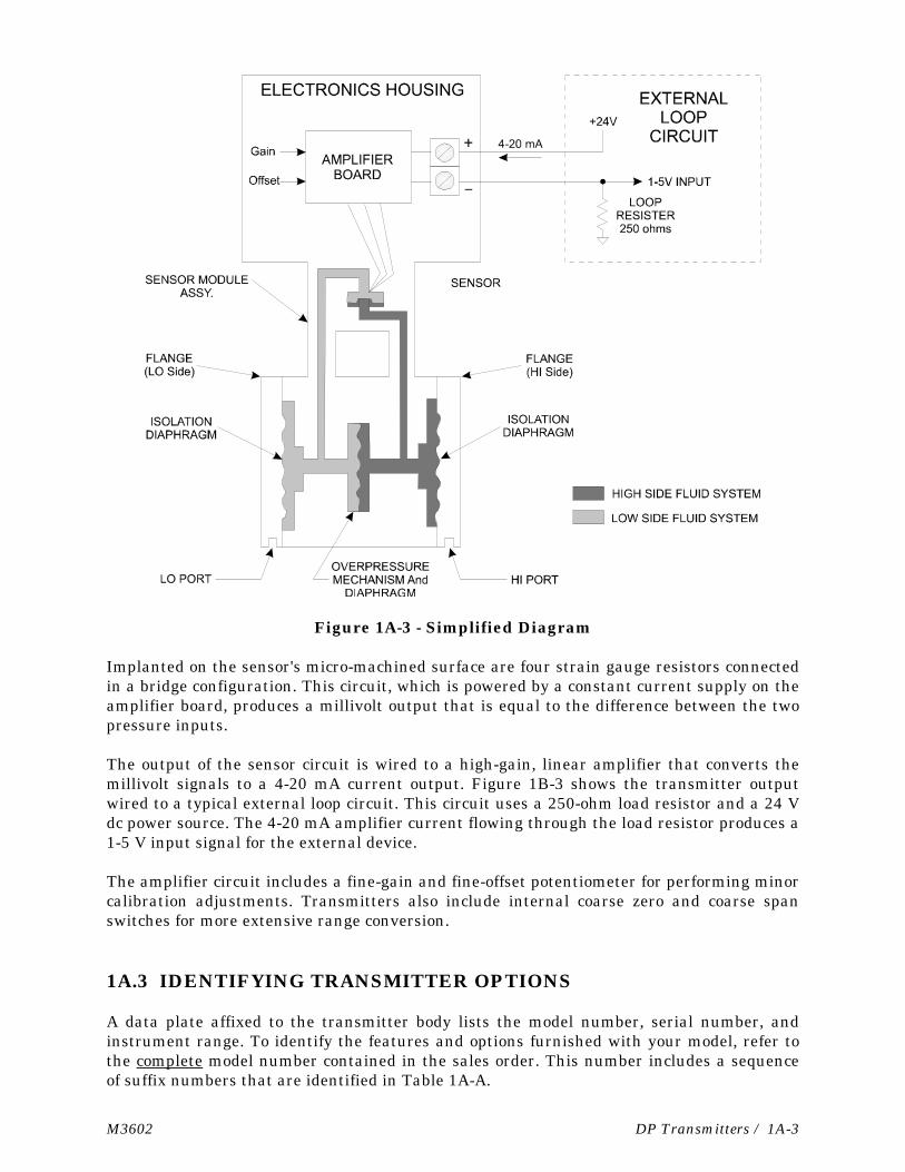
Figure 1A-3 - Simplified Diagram
Implanted on the sensor's micro-machined surface are four strain gauge resistors connectedin a bridge configuration. This circuit, which is powered by a constant current supply on theamplifier board, produces a millivolt output that is equal to the difference between the twopressure inputs.
The output of the sensor circuit is wired to a high-gain, linear amplifier that converts themillivolt signals to a 4-20 mA current output. Figure 1B-3 shows the transmitter outputwired to a typical external loop circuit. This circuit uses a 250-ohm load resistor and a 24 Vdc power source. The 4-20 mA amplifier current flowing through the load resistor produces a1-5 V input signal for the external device.
The amplifier circuit includes a fine-gain and fine-offset potentiometer for performing minorcalibration adjustments. Transmitters also include internal coarse zero and coarse spanswitches for more extensive range conversion.
1A.3 IDENTIFYING TRANSMITTER OPTIONS
A data plate affixed to the transmitter body lists the model number, serial number, andinstrument range. To identify the features and options furnished with your model, refer tothe complete model number contained in the sales order. This number includes a sequenceof suffix numbers that are identified in Table 1A-A.

1A-4 / DP Transmitters M3602
TABLE 1A-A - MODEL NUMBER BREAKDOWN FOR SERIES PX771A
PX771A - (1) – (2) (see Codes below)
(1) INPUT RANGE (2) OPTIONSCODE RANGE
100WCGI 0-17 to 0-100 inH2O300WCGI 0-50 to 0-300 inH2O025GI 0-4 to 0-25 psi100GI 0-17 to 0-100 psi300GI 0-50 to 0-300 psi
CODE DESCRIPTION
MB Mounting bracketM Local digital indicatorH Hastelloy C wetted parts
Figure 1A-4A - Overall Dimensions for Series PX771A Transmitter(With Flange Type Mounting Bracket
M3602 DP Transmitters / 1A-5
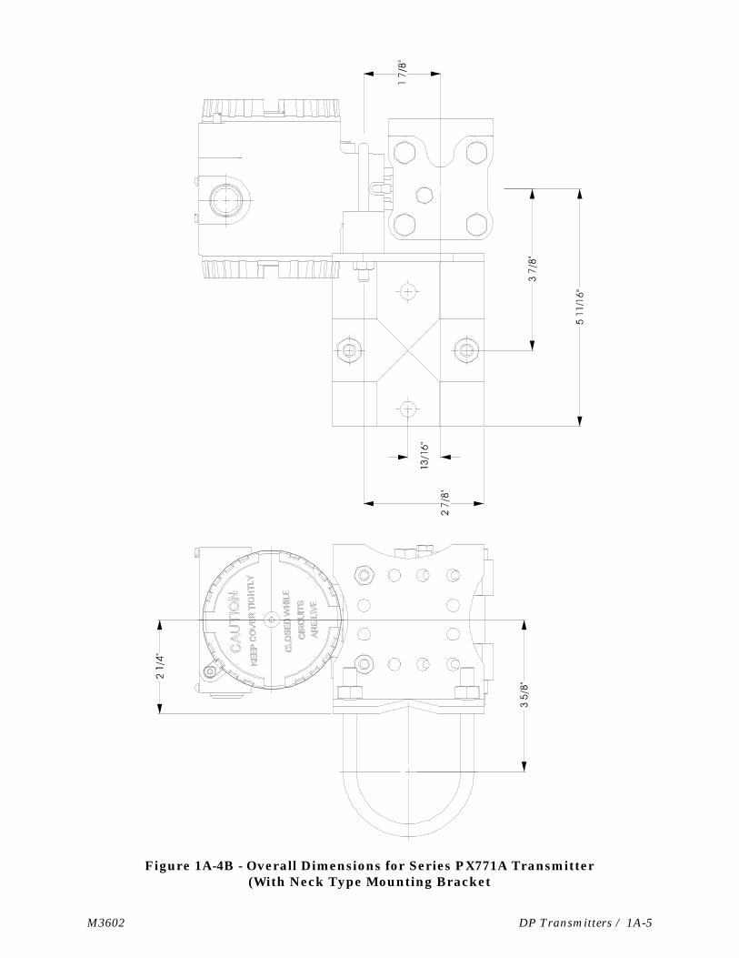
Figure 1A-4B - Overall Dimensions for Series PX771A Transmitter(With Neck Type Mounting Bracket
1A-6 / DP Transmitters M3602
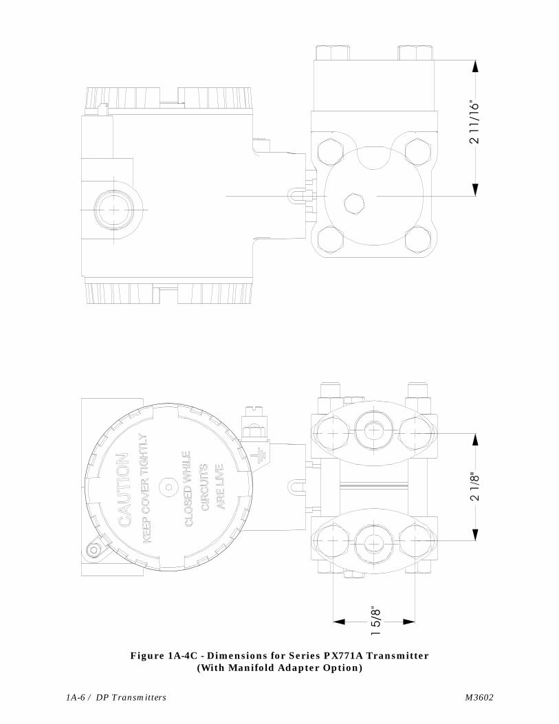
Figure 1A-4C - Dimensions for Series PX771A Transmitter(With Manifold Adapter Option)
M3602 DP Transmitters / 1A-7
1A.4 TRANSMITTER MOUNTING
The transmitter may be mounted in any position. However, when it leaves the factory it iscalibrated for operation in the upright position with the electronics enclosure at the top andthe DP connections at the bottom as shown in Figure 1B-2. If it is installed in a differentposition, the transmitter may require a slight zero adjustment. This procedure is describedin Section 3 Calibration.
The transmitter provides connection ports on the process flange as the standardarrangement. Optional manifold blocks may also be specified. Both arrangements aredescribed as follows:
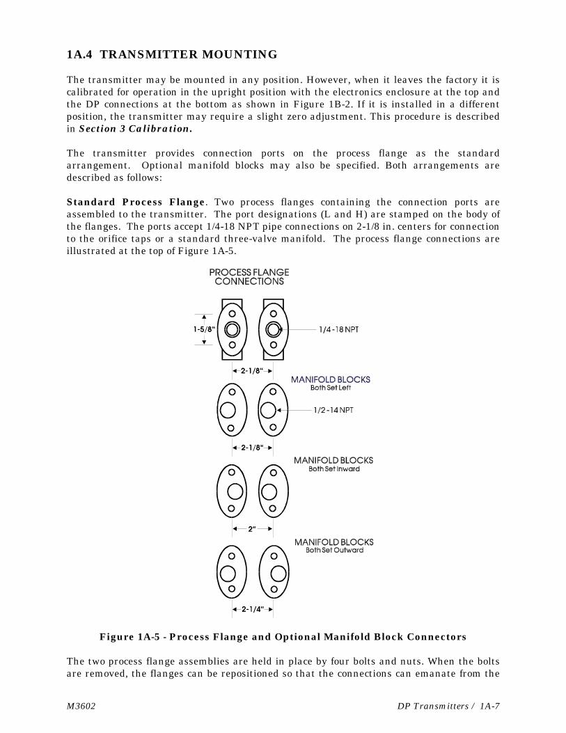
Standard Process Flange. Two process flanges containing the connection ports areassembled to the transmitter. The port designations (L and H) are stamped on the body ofthe flanges. The ports accept 1/4-18 NPT pipe connections on 2-1/8 in. centers for connectionto the orifice taps or a standard three-valve manifold. The process flange connections areillustrated at the top of Figure 1A-5.
Figure 1A-5 - Process Flange and Optional Manifold Block Connectors
The two process flange assemblies are held in place by four bolts and nuts. When the boltsare removed, the flanges can be repositioned so that the connections can emanate from the

1A-8 / DP Transmitters M3602
front, rear or bottom of the transmitter. Care should be taken not to damage the sensormodule assembly during this procedure. Once the flange has been positioned, the boltsshould be tightened in an alternating sequence to about 20-30 foot-pounds of torque.
Optional Process Manifold Block. Process manifold blocks may be installed on thetransmitter to permit the use of connector assemblies having different connection centers.The manifold blocks, which are oval in appearance, mate with the transmitter's processflange. The blocks may be installed in several positions to achieve different connectioncenters as shown in Figure 1A-5.
Vent Plug. Each process flange includes a 3/8 inch vent plug to bleed pressure lines. Tovent the unit, loosen the inner 5/32” Hex screw 1/4 turn. To perform calibration by applyingpressure to the flange, remove the plug with a 7/16” Hex Wrench and install a 1/4” NPTfitting. Be sure to secure both plugs upon completion.
Warning! Both vents may be under high pressure! Never loosen them more than 1/4 turn tobleed the lines. Secure both vents after bleeding is complete.
1A.4.1 Transmitter Housing Rotation
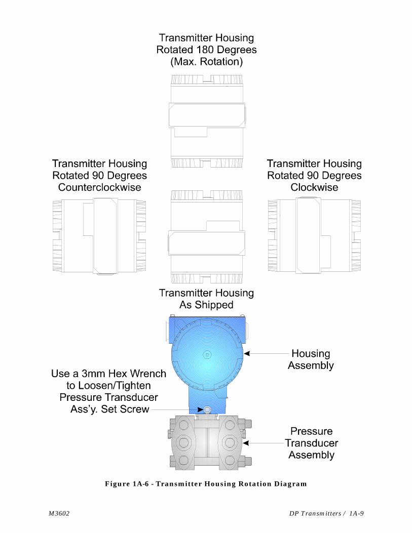
Once mounted, the Transmitter Housing can be rotated up to 180° in either direction, i.e.,clockwise or counterclockwise. The Transmitter Housing must not be rotated from itsshipped position any more than 180° clockwise or counterclockwise. CAUTION: Trans-mitter will be damaged if the Transmitter Housing is rotated more than 180° fromits shipped position.
To rotate the Transmitter Housing, the set screw that locks the Pressure Transducer to theTransmitter Housing must be removed with a 3mm Hex Wrench. Once the TransmitterHousing has been turned to the desired position, be sure to replace and tighten the setscrew (see Figure 1A-6).
M3602 DP Transmitters / 1A-9
Figure 1A-6 - Transmitter Housing Rotation Diagram
1A-10 / DP Transmitters M3602
1A.5 DP MEASUREMENT APPLICATIONS
The Series PX771A transmitter measures the differential pressure of pressurized liquids,gases, or steam. They can also be used to measure a column of liquid in a tank or vessel. Adiscussion of some basic applications follows:
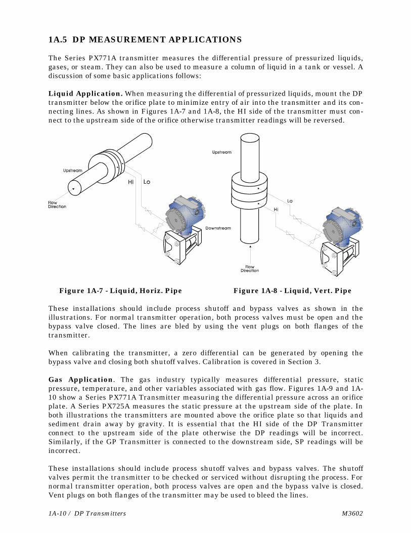
Liquid Application. When measuring the differential of pressurized liquids, mount the DPtransmitter below the orifice plate to minimize entry of air into the transmitter and its con-necting lines. As shown in Figures 1A-7 and 1A-8, the HI side of the transmitter must con-nect to the upstream side of the orifice otherwise transmitter readings will be reversed.
Figure 1A-7 - Liquid, Horiz. Pipe Figure 1A-8 - Liquid, Vert. Pipe
These installations should include process shutoff and bypass valves as shown in theillustrations. For normal transmitter operation, both process valves must be open and thebypass valve closed. The lines are bled by using the vent plugs on both flanges of thetransmitter.
When calibrating the transmitter, a zero differential can be generated by opening thebypass valve and closing both shutoff valves. Calibration is covered in Section 3.
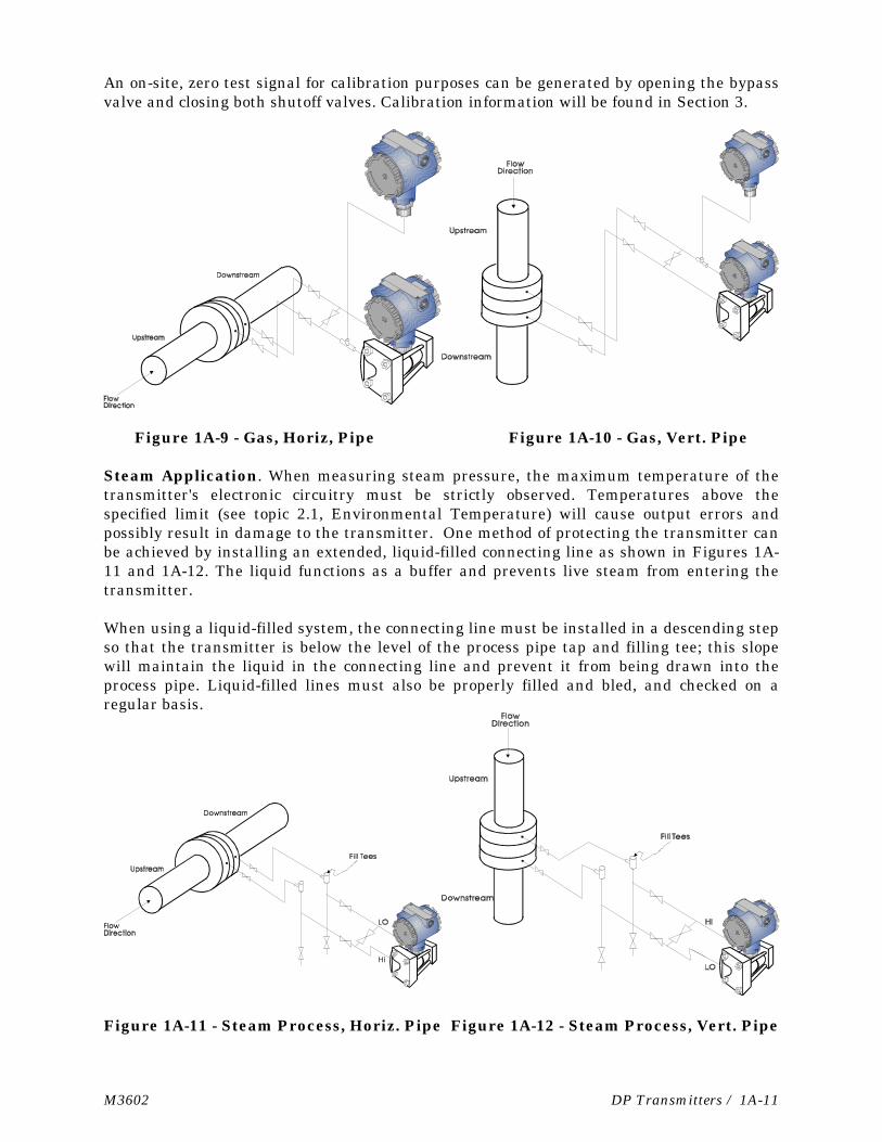
Gas Application. The gas industry typically measures differential pressure, staticpressure, temperature, and other variables associated with gas flow. Figures 1A-9 and 1A-10 show a Series PX771A Transmitter measuring the differential pressure across an orificeplate. A Series PX725A measures the static pressure at the upstream side of the plate. Inboth illustrations the transmitters are mounted above the orifice plate so that liquids andsediment drain away by gravity. It is essential that the HI side of the DP Transmitterconnect to the upstream side of the plate otherwise the DP readings will be incorrect.Similarly, if the GP Transmitter is connected to the downstream side, SP readings will beincorrect.
These installations should include process shutoff valves and bypass valves. The shutoffvalves permit the transmitter to be checked or serviced without disrupting the process. Fornormal transmitter operation, both process valves are open and the bypass valve is closed.Vent plugs on both flanges of the transmitter may be used to bleed the lines.
M3602 DP Transmitters / 1A-11
An on-site, zero test signal for calibration purposes can be generated by opening the bypassvalve and closing both shutoff valves. Calibration information will be found in Section 3.
Figure 1A-9 - Gas, Horiz, Pipe Figure 1A-10 - Gas, Vert. Pipe
Steam Application. When measuring steam pressure, the maximum temperature of thetransmitter's electronic circuitry must be strictly observed. Temperatures above thespecified limit (see topic 2.1, Environmental Temperature) will cause output errors andpossibly result in damage to the transmitter. One method of protecting the transmitter canbe achieved by installing an extended, liquid-filled connecting line as shown in Figures 1A-11 and 1A-12. The liquid functions as a buffer and prevents live steam from entering thetransmitter.
When using a liquid-filled system, the connecting line must be installed in a descending stepso that the transmitter is below the level of the process pipe tap and filling tee; this slopewill maintain the liquid in the connecting line and prevent it from being drawn into theprocess pipe. Liquid-filled lines must also be properly filled and bled, and checked on aregular basis.
Figure 1A-11 - Steam Process, Horiz. Pipe Figure 1A-12 - Steam Process, Vert. Pipe
1A-12 / DP Transmitters M3602
A liquid-filled line is one way to isolate the transmitter from a steam process. As an al-ternate method, a steam trap may be installed in the connecting line. Severalmanufacturers offer traps for this application.
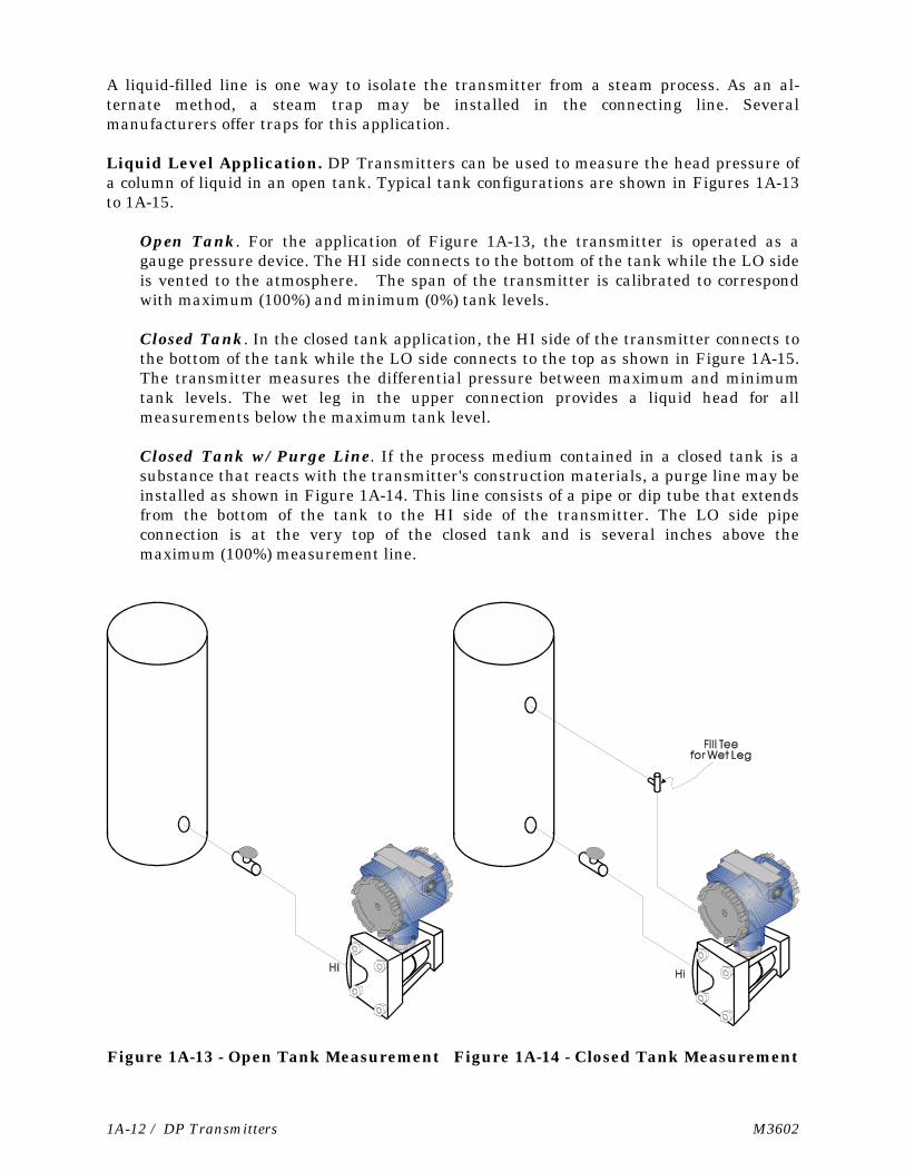
Liquid Level Application. DP Transmitters can be used to measure the head pressure ofa column of liquid in an open tank. Typical tank configurations are shown in Figures 1A-13to 1A-15.
Open Tank. For the application of Figure 1A-13, the transmitter is operated as agauge pressure device. The HI side connects to the bottom of the tank while the LO sideis vented to the atmosphere. The span of the transmitter is calibrated to correspondwith maximum (100%) and minimum (0%) tank levels.
Closed Tank. In the closed tank application, the HI side of the transmitter connects tothe bottom of the tank while the LO side connects to the top as shown in Figure 1A-15.The transmitter measures the differential pressure between maximum and minimumtank levels. The wet leg in the upper connection provides a liquid head for allmeasurements below the maximum tank level.
Closed Tank w/ Purge Line. If the process medium contained in a closed tank is asubstance that reacts with the transmitter's construction materials, a purge line may beinstalled as shown in Figure 1A-14. This line consists of a pipe or dip tube that extendsfrom the bottom of the tank to the HI side of the transmitter. The LO side pipeconnection is at the very top of the closed tank and is several inches above themaximum (100%) measurement line.
Figure 1A-13 - Open Tank Measurement Figure 1A-14 - Closed Tank Measurement
M3602 DP Transmitters / 1A-13
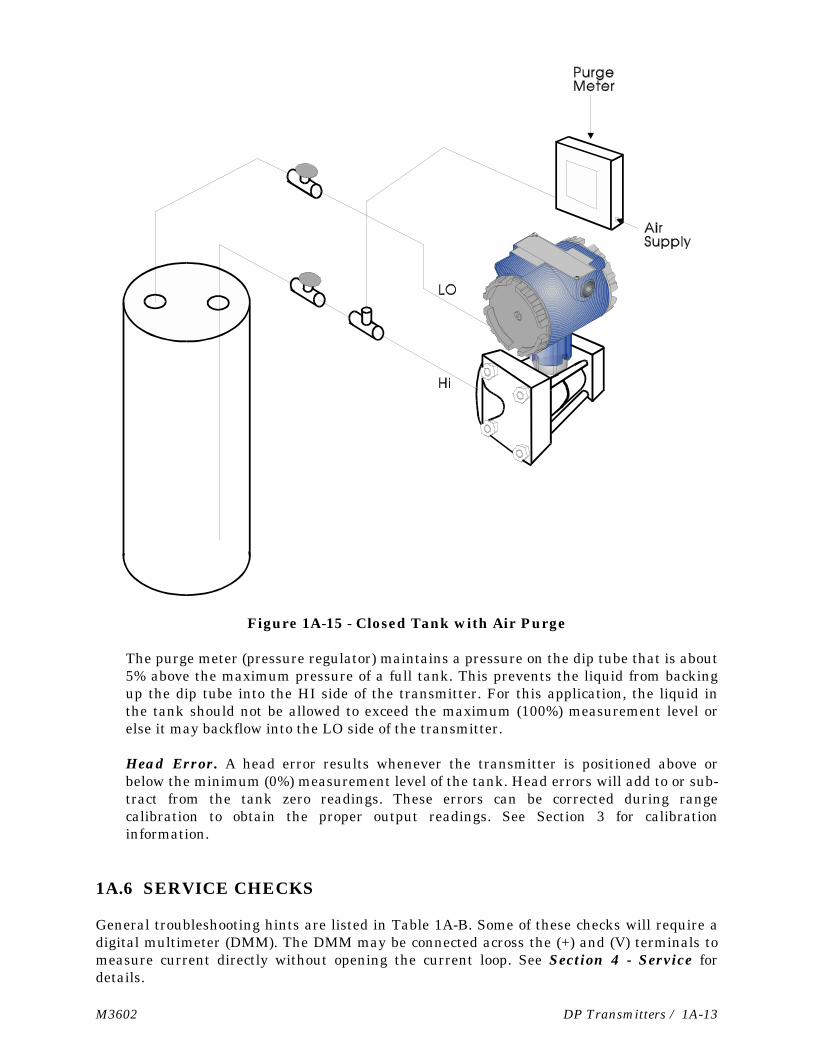
Figure 1A-15 - Closed Tank with Air Purge
The purge meter (pressure regulator) maintains a pressure on the dip tube that is about5% above the maximum pressure of a full tank. This prevents the liquid from backingup the dip tube into the HI side of the transmitter. For this application, the liquid inthe tank should not be allowed to exceed the maximum (100%) measurement level orelse it may backflow into the LO side of the transmitter.
Head Error. A head error results whenever the transmitter is positioned above orbelow the minimum (0%) measurement level of the tank. Head errors will add to or sub-tract from the tank zero readings. These errors can be corrected during rangecalibration to obtain the proper output readings. See Section 3 for calibrationinformation.
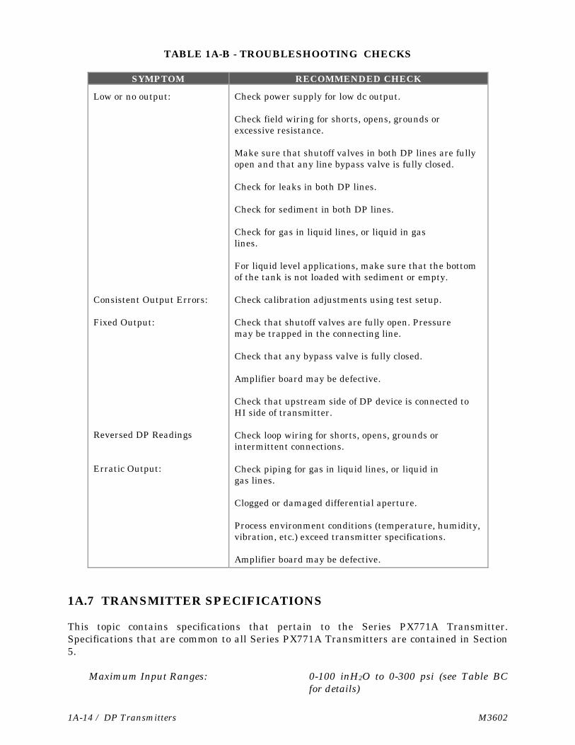
1A.6 SERVICE CHECKS
General troubleshooting hints are listed in Table 1A-B. Some of these checks will require adigital multimeter (DMM). The DMM may be connected across the (+) and (V) terminals tomeasure current directly without opening the current loop. See Section 4 - Service fordetails.
1A-14 / DP Transmitters M3602
TABLE 1A-B - TROUBLESHOOTING CHECKS
SYMPTOM RECOMMENDED CHECK
Low or no output:
Consistent Output Errors:
Fixed Output:
Reversed DP Readings
Erratic Output:
Check power supply for low dc output.
Check field wiring for shorts, opens, grounds orexcessive resistance.
Make sure that shutoff valves in both DP lines are fullyopen and that any line bypass valve is fully closed.
Check for leaks in both DP lines.
Check for sediment in both DP lines.
Check for gas in liquid lines, or liquid in gaslines.
For liquid level applications, make sure that the bottomof the tank is not loaded with sediment or empty.
Check calibration adjustments using test setup.
Check that shutoff valves are fully open. Pressuremay be trapped in the connecting line.
Check that any bypass valve is fully closed.
Amplifier board may be defective.
Check that upstream side of DP device is connected toHI side of transmitter.
Check loop wiring for shorts, opens, grounds orintermittent connections.
Check piping for gas in liquid lines, or liquid ingas lines.
Clogged or damaged differential aperture.
Process environment conditions (temperature, humidity,vibration, etc.) exceed transmitter specifications.
Amplifier board may be defective.
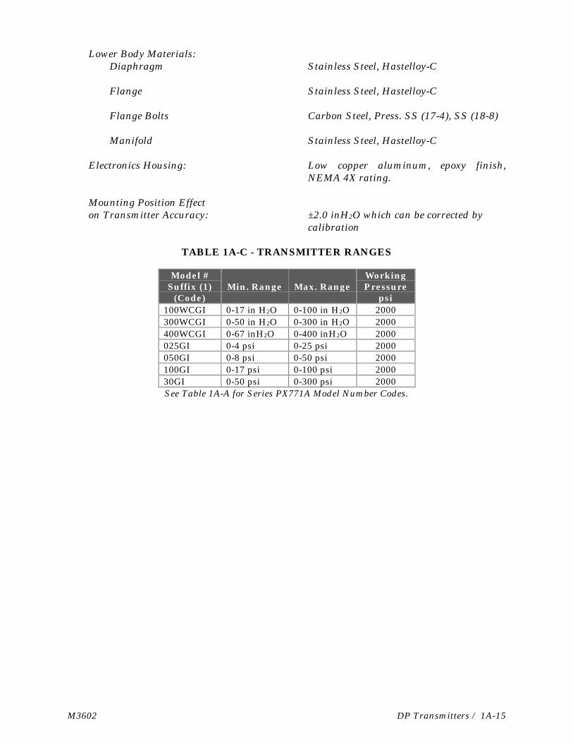
1A.7 TRANSMITTER SPECIFICATIONS
This topic contains specifications that pertain to the Series PX771A Transmitter.Specifications that are common to all Series PX771A Transmitters are contained in Section5.
Maximum Input Ranges: 0-100 inH2O to 0-300 psi (see Table BCfor details)
M3602 DP Transmitters / 1A-15
Lower Body Materials:Diaphragm Stainless Steel, Hastelloy-C
Flange Stainless Steel, Hastelloy-C
Flange Bolts Carbon Steel, Press. SS (17-4), SS (18-8)
Manifold Stainless Steel, Hastelloy-C
Electronics Housing: Low copper aluminum, epoxy finish,NEMA 4X rating.
Mounting Position Effecton Transmitter Accuracy: ±2.0 inH2O which can be corrected by
calibration
TABLE 1A-C - TRANSMITTER RANGES
Model #Suffix (1)
(Code)Min. Range Max. Range
WorkingPressure
psi100WCGI 0-17 in H2O 0-100 in H2O 2000300WCGI 0-50 in H2O 0-300 in H2O 2000400WCGI 0-67 inH2O 0-400 inH2O 2000025GI 0-4 psi 0-25 psi 2000050GI 0-8 psi 0-50 psi 2000100GI 0-17 psi 0-100 psi 200030GI 0-50 psi 0-300 psi 2000See Table 1A-A for Series PX771A Model Number Codes.
M-3602 Installation / 2-1
Section 2INSTALLATION
2.1 INSTALLATION NOTES
Prior to installing the transmitter, factors such as environmental temperature, main-tenance access, and transmitter construction materials will require consideration.
Environmental Temperature: The temperature operating ranges for the wet end and elec-tronics assemblies of the transmitter are as follows:
1. Wet end w/ DC 200 fill: -40 to 220°F (-40 to 104°C) 2. Electronic - Amplifier Board -25 to 185°F (-32 to 85°C) 3. Electronic - Digital Indicator -22 to 158°F (-30 to 70°C)
When installing a transmitter, it is important to consider the temperature range of allitems listed above as each has different limits. For example, if item 1 were at the upperlimit of its range (220°F), item 2 would be 35°F over its limit of 185°F. Likewise, if thesame transmitter included a digital indicator, item 3, the indicator would be 62°F above its158°F limit.
Under no circumstances should the internal temperature of the electronics housing be al-lowed to go above the upper limits specified above for items 2 and 3. Doing so will causeoutput errors, and possibly result in damage to the electronic assemblies. Going below thelower temperature limit can also lead to performance or failure problems. If temperatureextremes are anticipated, the transmitter should be installed in a more favorable en-vironment or be provided with other means of protection.
Caution: The transmitter must always be operated within the temperature range of its wetend and electronic assemblies. Prolonged operation under extreme conditions could resultin eventual transmitter damage.
Maintenance Access: Select a site that provides ease of access for maintenance and repairs.Inspect the site for any potential hazards that could result in accidental damage to equip-ment or injury to persons. Clearly post any dangers that may not be apparent to operators.
Construction Materials: Prior to mounting the transmitter, check its construction materialsto insure that they are compatible with the process medium. Some gases or liquids willreact with certain metals and result in permanent damage to the transmitter. This type ofdamage is not covered under the warranty agreement.
2.2 INSTALLATIONS IN HAZARDOUS AREAS
The information that follows only applies to transmitter models approved for use inhazardous areas. Models without approval must never be used for these installations.

2-2 / Installation M-3602
The installation of equipment in hazardous areas must comply with the National ElectricalCode ANSI/NFPA-70, and ANSI/ISA S82.01, S82.02, & S82.03 standards. Transmitterscertified for use in hazardous areas will have the mark of the certifying agency inscribed onthe transmitter data plate.
The checklist that follows emphasizes some key points of safety with regard to installationsin hazardous areas.
1. All transmitter wiring that passes through hazardous areas must be enclosed in metalconduit. The point where the conduit connection feeds into the transmitter’s housingmust be properly secured to prevent entry of gases or other ignitable substances intothe transmitter. Explosion-proof wiring practices must be followed to prevent flashbackthrough the conduit.
2. The cover of the transmitter must be screwed in hand tight and fully seated. The cover
must be replaced if it is damaged or shows stripped threads. 3. The cover of the unit must always be in place and secured when the transmitter is
powered. The cover must never be loosened or removed unless the atmosphere is madesafe or all electrical power is removed from the transmitter.
WARNING: Removing the cover of a transmitter while it is operating in a hazardous areais dangerous and could result in fire or explosion.
WARNING: EXPLOSION HAZARDDo Not disconnect equipment unless power has been disconnected and the area
is known to be nonhazardous.
Figure 2-1 - Dressing of Wire Leads
2.3 ELECTRICAL WIRING NOTES
All wiring connections cited in the text and illustrations must conform to the NationalElectrical Code, and local authority. Only technically qualified persons should performwiring procedures.
M-3602 Installation / 2-3
Conduit Connection: The transmitter provides a ½ inch NPT threaded female port forelectrical conduit. This port can mate with threaded conduit or an appropriate threadedpipe adapter.
Note: The conduit connections must be secured with no less than five threads fullyengaged.
In some applications, condensation could form in the conduit, and seep into the transmitterelectronics housing. If allowed to continue, moisture build-up will degrade the transmitterperformance, and eventually cause damage. Installing the transmitter above the level ofthe process connection can prevent this condition. Any moisture forming in the conduit willthen drain away by gravity.
Access to Wiring Terminals: Remove the threaded end cover to access the wiring terminals(see Figure 3-2). If the cover cannot be loosened by hand, insert a flat metal bar or similartool between the cover protrusions and apply moderate counter-clockwise leverage. Beforere-installing the cover, make sure that the threads are clean. Tighten the cover by handuntil all threads are engaged, and the gasket is compressed.
Lead Dress: When feeding wire through the conduit opening of the transmitter, add aboutsix inches of slack for terminal connections. Dress the leads in a circular path around theterminals as seen in Figure 2-1. The additional slack will make the connections moremanageable and prevent mechanical strain on the terminals.
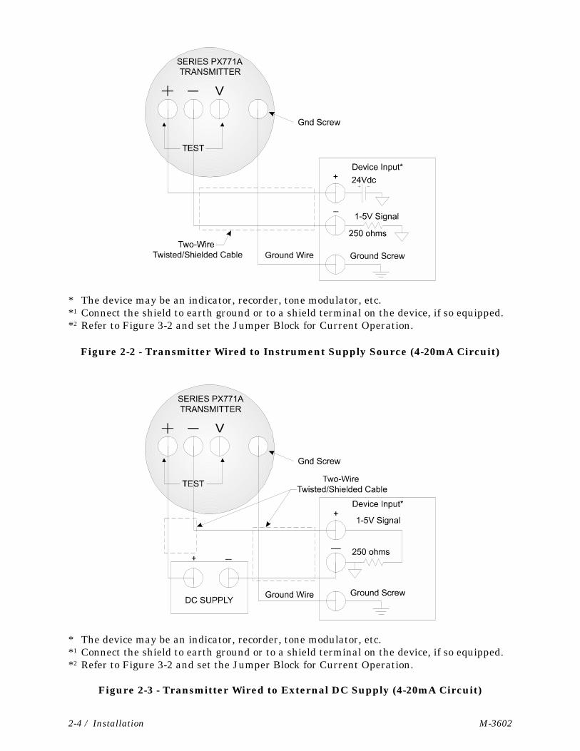
2.4 WIRING OF 4-20mA SIGNAL/POWER LOOP
The 4-20mA signal/power loop can be powered in two ways. Figure 2-2 shows the looppowered by the receiving device (controller, recorder, etc.), while Figure 2-3 shows the looppowered by an external supply. In both instances, the 4-20mA current flows through a250Ω load resistor and develops a corresponding 1-5V input for the receiving device.
Signal Shielding: Use twisted wire, shielded cable covered by insulating material for thesignal/power wiring. When properly grounded, this cable will minimize pickup of elec-tromagnetic, and radio frequency interference.
The shield lead of the cable is typically grounded at the input of the receiving device(computer controller, recorder, etc.) as shown in Figures 2-2 and 2-3. Never connect theother end of this shield to the transmitter enclosure or attempt to ground the shield atmore than one point along the wire path. Multiple grounds will cause signal errors at theinput of the receiving device.
Although it is recommended to connect the cable’s shield to the power common return ofthe receiving device, the actual connection point may differ depending on the design andapplication of the device. In some instances, better noise immunity can be had byconnecting the cable shield to the chassis or a designated shield terminal on the device.Check the instruction manual of the receiving device for the recommended connectionpoints.
2-4 / Installation M-3602
* The device may be an indicator, recorder, tone modulator, etc.*1 Connect the shield to earth ground or to a shield terminal on the device, if so equipped.*2 Refer to Figure 3-2 and set the Jumper Block for Current Operation.
Figure 2-2 - Transmitter Wired to Instrument Supply Source (4-20mA Circuit)
* The device may be an indicator, recorder, tone modulator, etc.*1 Connect the shield to earth ground or to a shield terminal on the device, if so equipped.*2 Refer to Figure 3-2 and set the Jumper Block for Current Operation.
Figure 2-3 - Transmitter Wired to External DC Supply (4-20mA Circuit)
M-3602 Installation / 2-5
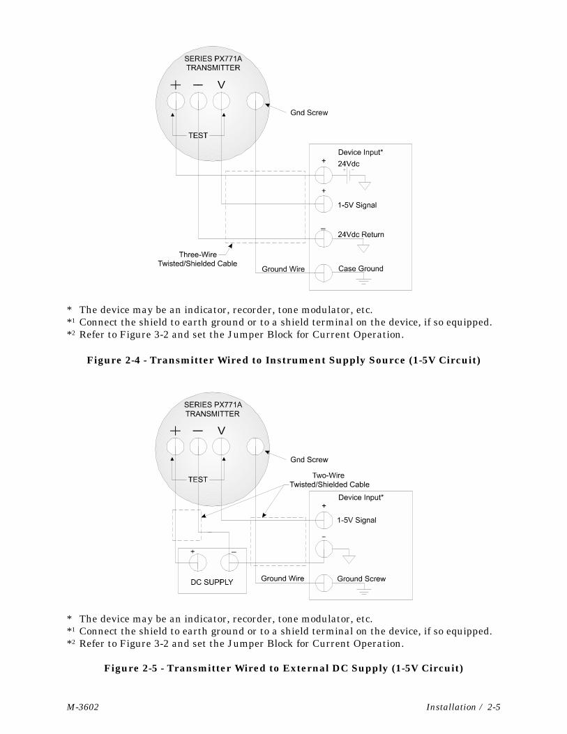
* The device may be an indicator, recorder, tone modulator, etc.*1 Connect the shield to earth ground or to a shield terminal on the device, if so equipped.*2 Refer to Figure 3-2 and set the Jumper Block for Current Operation.
Figure 2-4 - Transmitter Wired to Instrument Supply Source (1-5V Circuit)
* The device may be an indicator, recorder, tone modulator, etc.*1 Connect the shield to earth ground or to a shield terminal on the device, if so equipped.*2 Refer to Figure 3-2 and set the Jumper Block for Current Operation.
Figure 2-5 - Transmitter Wired to External DC Supply (1-5V Circuit)
2-6 / Installation M-3602
2.5 WIRING OF 1-5V SIGNAL/POWER LOOP
The 1-5V signal/power loop can be powered in two ways, by the receiving device (controller,recorder, etc.), or by an external supply. Provide a setup similar to that shown in eitherFigure 2-4 or 2-5. Apply +24V across the + and - terminals of the transmitter as shown,whether supplied by an external supply, or by the receiving device. Next, connect the 1-5Voutput, or the terminal block labeled V to the input of the device. Notice: Unlike thecurrent loop, this input must be analog ground referenced, and not passed through asampling resistor.
Signal Shielding: Use twisted, three wire, shielded cable covered by insulating material forthe signal/power wiring. For further information regarding signal shielding, consult section2.4.
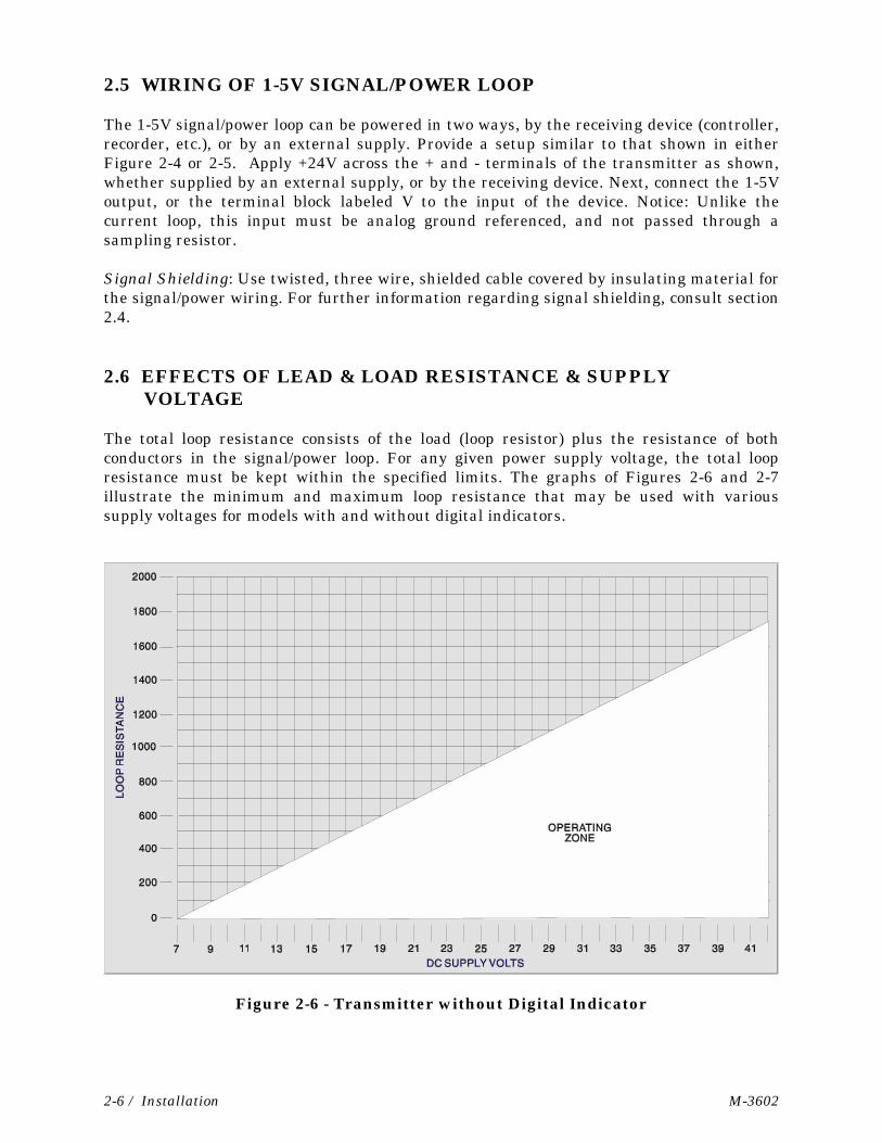
2.6 EFFECTS OF LEAD & LOAD RESISTANCE & SUPPLY VOLTAGE
The total loop resistance consists of the load (loop resistor) plus the resistance of bothconductors in the signal/power loop. For any given power supply voltage, the total loopresistance must be kept within the specified limits. The graphs of Figures 2-6 and 2-7illustrate the minimum and maximum loop resistance that may be used with varioussupply voltages for models with and without digital indicators.
Figure 2-6 - Transmitter without Digital Indicator
M-3602 Installation / 2-7
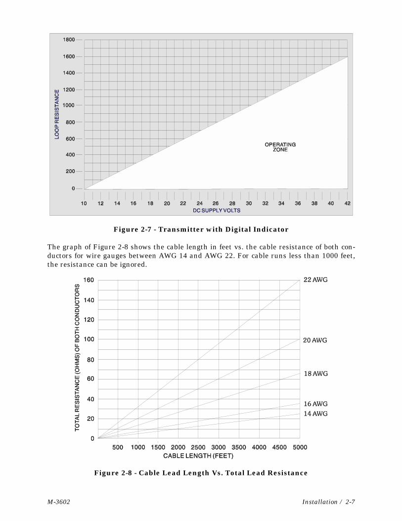
Figure 2-7 - Transmitter with Digital Indicator
The graph of Figure 2-8 shows the cable length in feet vs. the cable resistance of both con-ductors for wire gauges between AWG 14 and AWG 22. For cable runs less than 1000 feet,the resistance can be ignored.
Figure 2-8 - Cable Lead Length Vs. Total Lead Resistance
M-3602 Calibration / 3-1
Section 3CALIBRATION
3.1 CALIBRATION SETUP
Equipment Required: Transmitter calibration requires a laboratory bench setup with thefollowing equipment:
1. Test source capable of generating fixed pressure values equivalent to 0%, and 100%values of transmitter’s range (URL).
2. Pressure monitor device to read test source (±.025% accuracy)3. Electrical supply source capable of producing 24V-DC power to the transmitter.4. Digital Multimeter (DMM) with a 5-1/2 digit scale (±.005% accuracy)5. Current Sampling Resistor (250Ω, ±.01%, 1/4W)
Lab Vs. On-Site Setup: Although it is more convenient and recommended to perform thisprocedure using a laboratory setup, calibration can also be performed on site providing thatthe connecting line or flange is equipped with a calibration tap and appropriate shutoff andbypass valves. This added equipment allows you to feed in an external test pressure sourceor use the process pressure as a reference signal. In the latter setup, the valves are closedto seal a fixed pressure in the connecting line. Only fine calibration using the externaladjustments should be attempted in wet, dusty, or hazardous environments.
Before attempting on-site calibration, carefully check the application. If the transmitter isoperated in a closed control loop configuration, either the transmitter must be isolatedfrom the process, or the process must be turned off. If this is not done, a critical processcould accidentally be driven into a dangerous region causing damage to equipment andproperty, and injury to persons.
Note: Before starting any test procedures, make sure that the transmitter is firmlyanchored in its intended operating position. A different mounting position can affect zerocalibration for some ranges and necessitate re-calibration.
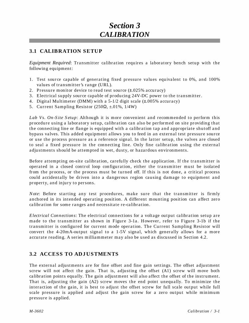
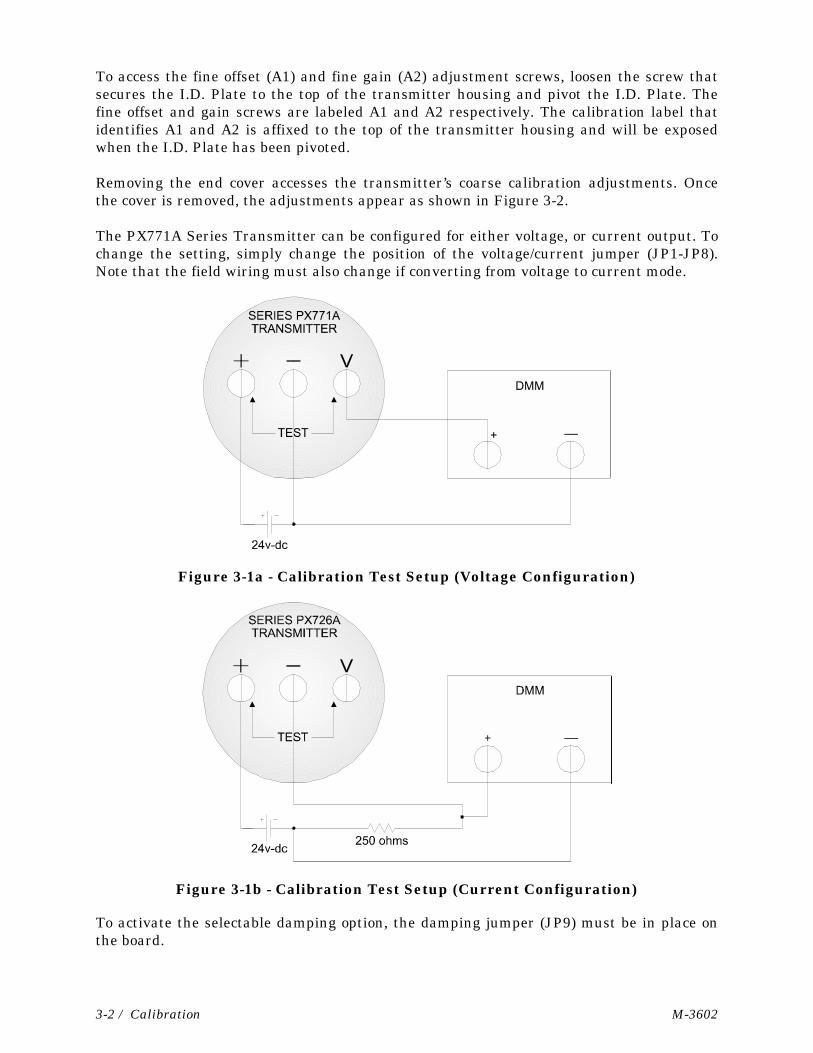
Electrical Connections: The electrical connections for a voltage output calibration setup aremade to the transmitter as shown in Figure 3-1a. However, refer to Figure 3-1b if thetransmitter is configured for current mode operation. The Current Sampling Resistor willconvert the 4-20mA-output signal to a 1-5V signal, which generally allows for a moreaccurate reading. A series milliammeter may also be used as discussed in Section 4.2.
3.2 ACCESS TO ADJUSTMENTS
The external adjustments are for fine offset and fine gain settings. The offset adjustmentscrew will not affect the gain. That is, adjusting the offset (A1) screw will move bothcalibration points equally. The gain adjustment will also affect the offset of the instrument.That is, adjusting the gain (A2) screw moves the end point unequally. To minimize theinteraction of the gain, it is best to adjust the offset screw for full scale output while fullscale pressure is applied and adjust the gain screw for a zero output while minimumpressure is applied.
3-2 / Calibration M-3602
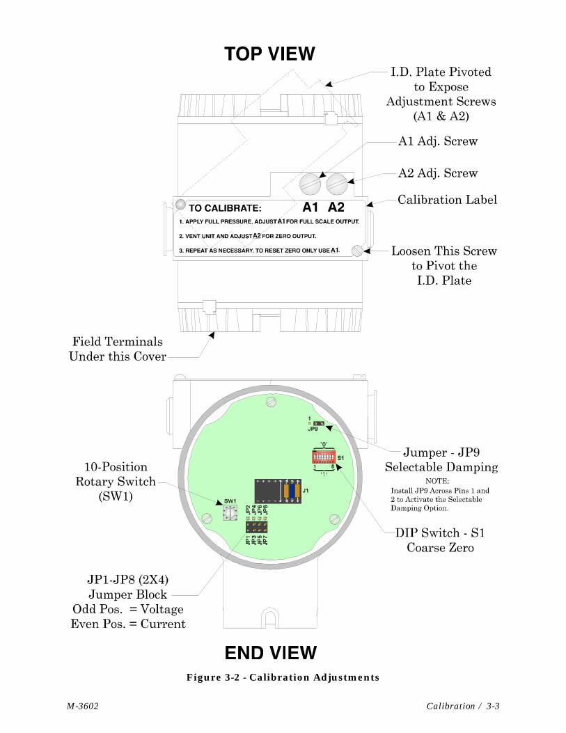
To access the fine offset (A1) and fine gain (A2) adjustment screws, loosen the screw thatsecures the I.D. Plate to the top of the transmitter housing and pivot the I.D. Plate. Thefine offset and gain screws are labeled A1 and A2 respectively. The calibration label thatidentifies A1 and A2 is affixed to the top of the transmitter housing and will be exposedwhen the I.D. Plate has been pivoted.
Removing the end cover accesses the transmitter’s coarse calibration adjustments. Oncethe cover is removed, the adjustments appear as shown in Figure 3-2.
The PX771A Series Transmitter can be configured for either voltage, or current output. Tochange the setting, simply change the position of the voltage/current jumper (JP1-JP8).Note that the field wiring must also change if converting from voltage to current mode.
Figure 3-1a - Calibration Test Setup (Voltage Configuration)
Figure 3-1b - Calibration Test Setup (Current Configuration)
To activate the selectable damping option, the damping jumper (JP9) must be in place onthe board.
M-3602 Calibration / 3-3
Figure 3-2 - Calibration Adjustments
3-4 / Calibration M-3602
3.3 EXTERNAL CHECK PROCEDURE
The general check procedure determines the accuracy of the transmitter at its calibratedoperating range. It uses the offset (A1) and the gain (A2) adjustment screws for minorcalibration corrections. Proceed as follows:
1. Provide a test setup as shown in Figure 3-1a or 3-1b depending on whether the unit hasbeen configured for current or voltage mode. Make sure that no electrical power is ap-plied to the transmitter while making connections. The Multimeter must be set in“Voltage” mode.
2. Set the DMM to a scale that will cover a 1-5Vdc range.
3. Apply 24Vdc power to the transmitter.
4. Set the pressure test source for a precise 0% range value. The DMM should display1.00Vdc ± 4mV (4mA dc ± 0.016mA).
5. Similarly, adjust the pressure test source for 100% range value. The DMM should read5.00Vdc ± 4mV (20mA dc ± 0.016mA).
6. If the readings of steps 4 to 6 are within tolerance, no calibration is required. Testing iscomplete. However, if any readings were in error, proceed to step 7.
7. Set the test pressure source to 100%. If this reading is out of tolerance, correct it byturning the A1 adjustment screw (clockwise rotation increases the reading).
8. Reset the test pressure source to 0%. If this reading is out of tolerance, correct it byturning the A2 adjustment screw (clockwise rotation decreases the reading).
9. Recheck the 0%, and 100% readings. Repeat steps 7 and 8 as needed. This may need tobe done two or three times. If errors are still present at full-scale pressure, recheck theswitch settings. If the DIP Switch is in the correct configuration, proceed to step 10. Iferrors are encountered at 0%, recheck the Rotary Switch settings. If the switch is in thecorrect position, proceed to step 10.
10. If the above three readings cannot be brought into proper calibration, the transmittermay require service or replacement. See Section 5, Service, for troubleshooting hints.
3.4 CALIBRATION ADJUSTMENTS
The range changing procedure uses the coarse span (SW1) and zero switches (S1:1-8),along with the fine offset (A1), and gain (A2) adjustment screws. The locations of theswitches are shown in Figure 3-2. The equipment setup required to perform rangechanging is the same as that described in topic 3.1. The coarse zero switches are containedin a single DIP switch package, with the switches labeled from 1 to 8, with either a “1” or a“0” silk-screened on the board. The coarse span switch is a 10 position rotary switch.
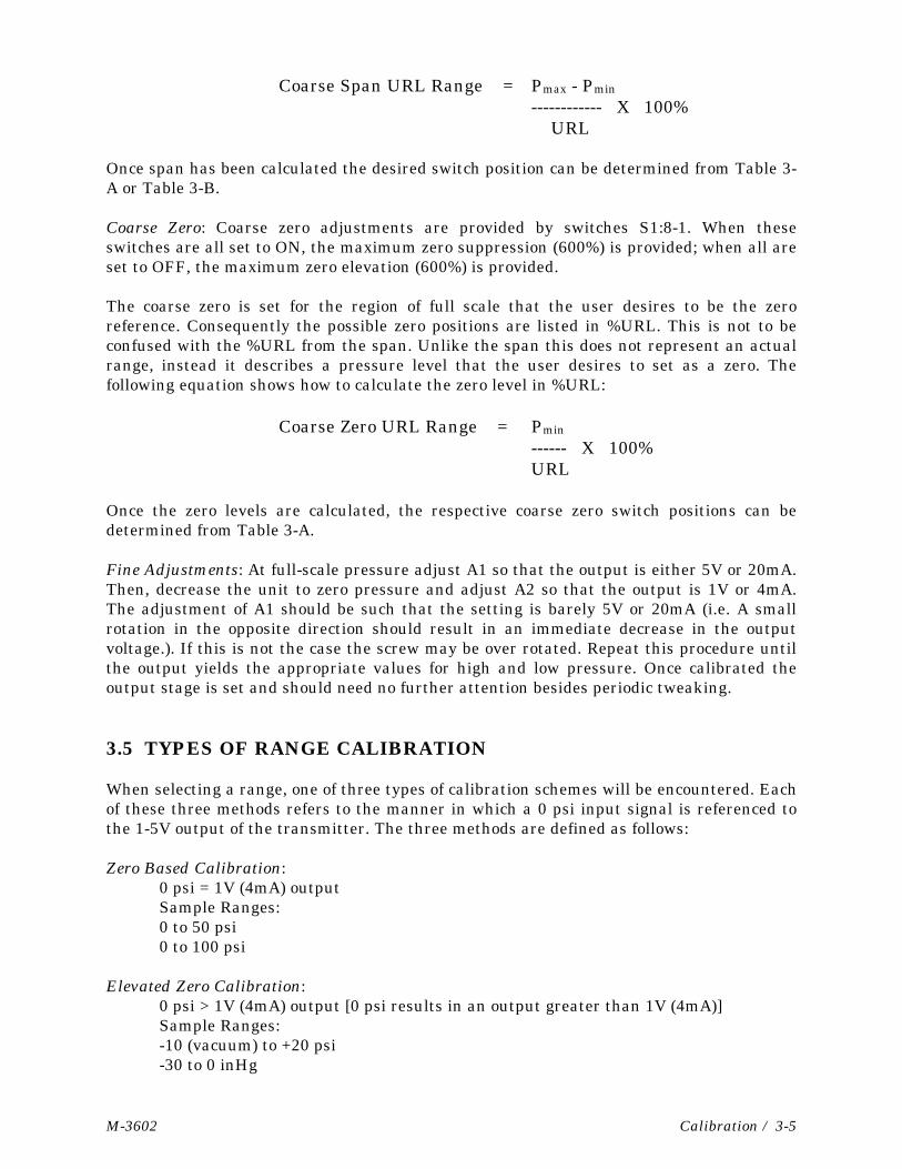
Coarse Span: The coarse span is set, by rotating the switch SW1, such that the desiredrange of full scale is available. Span can be calculated using the formula below.
M-3602 Calibration / 3-5
Coarse Span URL Range = Pmax - Pmin
------------ X 100% URL
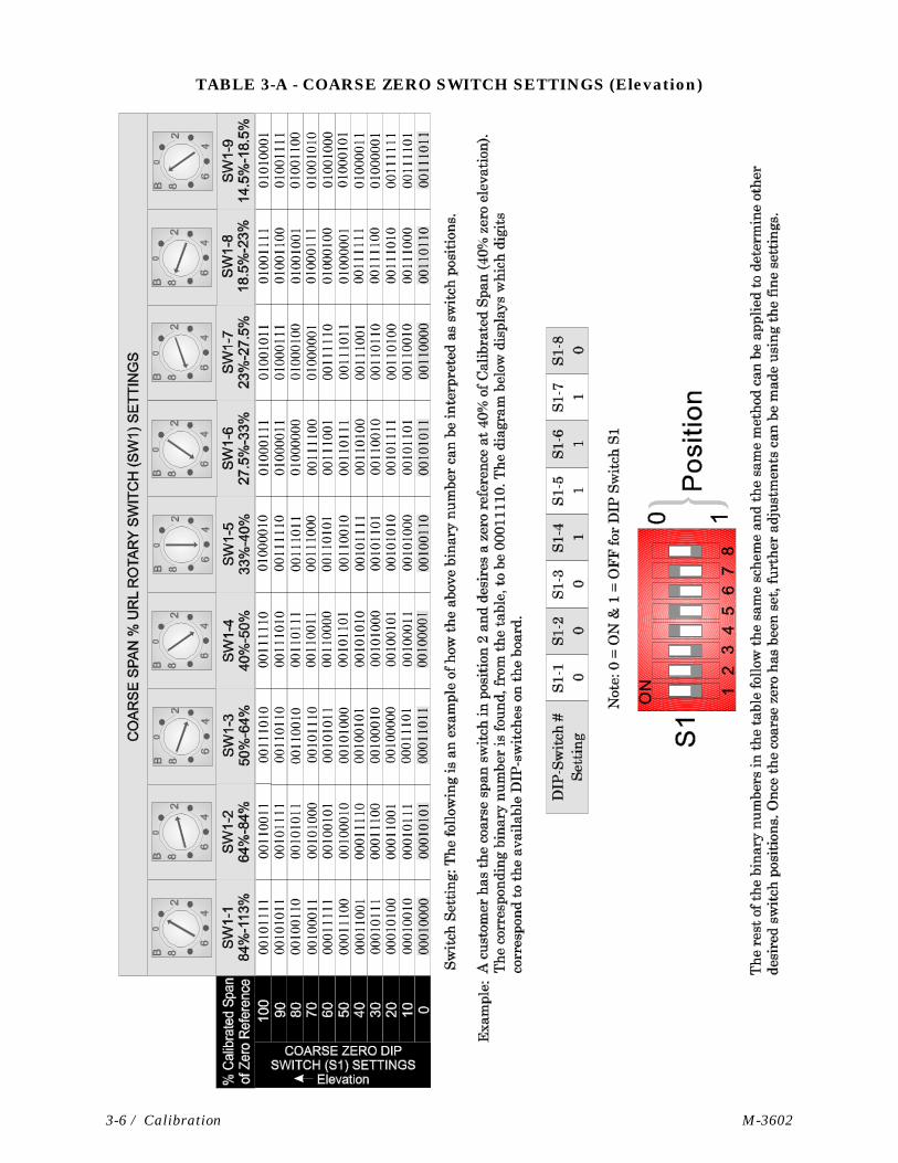
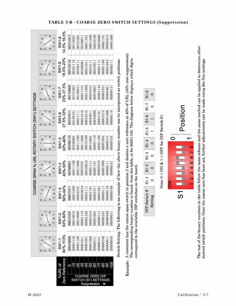
Once span has been calculated the desired switch position can be determined from Table 3-A or Table 3-B.
Coarse Zero: Coarse zero adjustments are provided by switches S1:8-1. When theseswitches are all set to ON, the maximum zero suppression (600%) is provided; when all areset to OFF, the maximum zero elevation (600%) is provided.
The coarse zero is set for the region of full scale that the user desires to be the zeroreference. Consequently the possible zero positions are listed in %URL. This is not to beconfused with the %URL from the span. Unlike the span this does not represent an actualrange, instead it describes a pressure level that the user desires to set as a zero. Thefollowing equation shows how to calculate the zero level in %URL:
Coarse Zero URL Range = Pmin
------ X 100%URL
Once the zero levels are calculated, the respective coarse zero switch positions can bedetermined from Table 3-A.
Fine Adjustments: At full-scale pressure adjust A1 so that the output is either 5V or 20mA.Then, decrease the unit to zero pressure and adjust A2 so that the output is 1V or 4mA.The adjustment of A1 should be such that the setting is barely 5V or 20mA (i.e. A smallrotation in the opposite direction should result in an immediate decrease in the outputvoltage.). If this is not the case the screw may be over rotated. Repeat this procedure untilthe output yields the appropriate values for high and low pressure. Once calibrated theoutput stage is set and should need no further attention besides periodic tweaking.
3.5 TYPES OF RANGE CALIBRATION
When selecting a range, one of three types of calibration schemes will be encountered. Eachof these three methods refers to the manner in which a 0 psi input signal is referenced tothe 1-5V output of the transmitter. The three methods are defined as follows:
Zero Based Calibration:0 psi = 1V (4mA) outputSample Ranges:0 to 50 psi0 to 100 psi
Elevated Zero Calibration:0 psi > 1V (4mA) output [0 psi results in an output greater than 1V (4mA)]Sample Ranges:-10 (vacuum) to +20 psi-30 to 0 inHg
3-6 / Calibration M-3602
TABLE 3-A - COARSE ZERO SWITCH SETTINGS (Elevation)
M-3602 Calibration / 3-7
TABLE 3-B - COARSE ZERO SWITCH SETTINGS (Suppression)
3-8 / Calibration M-3602
Suppressed Zero Calibration:0 psi < 1V (4-20mA) output [0 psi results in an output less than 1V (4mA)]Sample Ranges:1 to 10 psi10 to 60 psi50 to 100 psi
The above procedures are described in topics 3.6, 3.7, and 3.8. Select the procedure yourequire.
3.6 ZERO-BASED CALIBRATION
This procedure describes the process by which the zero and span settings are obtained forthe 1-5V and 4-20mA output stages of the Series PX726A transmitters.
The following parameters relate directly to the calibration process:
URL: Upper Range Limit of sensing element. The URL is the maximum inputpressure that can be applied without over-pressuring the sensingelement.
Span: The algebraic difference between the limits of the range (Pmax – Pmin).The desired span must always be less than or equal to the upper rangelimit (URL) of the sensing element. Span is expressed as a percentageof the upper range limit of the sensing element.
Zero: The point within the available pressure range the user defines as a zeropressure reference.
Pmax: Maximum input pressure of a desired range, not necessarily themaximum range of the sensing unit.
Pmin: Minimum input pressure of a desired range.
Theory of Operation: The output stage can potentially take a user defined portion of the 0-100% URL pressure input, and display it as a corresponding 1-5V or 4-20mA output. Therange, desired by the user, is obtained by setting the appropriate coarse and fine zero andspan settings. Each coarse setting is described in Tables 3-A and 3-B, whereas the finesettings are adjusted manually until the desired output is achieved. Fine adjustments aremade with two external adjustment screws. The output stage is designed to yield a TurnDown of better than 6, while the fine adjustment screws should affect the output zero andspan by no more than 1.5%/Turn.
3.7 ELEVATED ZERO CALIBRATION
1. Calculate the total span required for the elevated zero range. For example, if thedesired elevated zero range is -10 to +30 psi, the total span will be 30-(-10) = 40 psi.
M-3602 Calibration / 3-9
2. Calculate the desired output reading for 0 psi. For this example, 0 psi = 25% of the spanfrom -10 to 30 psi. The output should therefore be 25% of the way from 1-5V, or2V(8mA). Set the Dip and Rotary switches in accordance with Table 3-A. Elevated zerovalues are expressed as positive percentages of calibrated span. Zero percent representszero elevation. If the desired percent elevation is in between values listed in the table,try the next closest setting.
3. Apply a 100% pressure input to the transmitter equivalent to the upper range value
(URV). For this example, URV = 30 psi. 4. If transmitter output is not 5.000V (20.00mA), adjust A1 to make a minor correction. 5. Vent the input pressure. Adjust A2 to set the output to the 0 psi reading calculated
above. 6. Recheck the transmitter output with the input pressure vented, and 100% inputs. The
DMM should provide respective readings of the output calculated above, and 5V (20mA)(± 0.15% full scale).
7. If necessary, repeat the A1 and A2 adjustment procedures. 8. If problems persist, recheck the DIP switch settings. Try setting the switches to the
lower percentage. For instance, if the desired percent elevation is 15%, set the switchesfor an elevation of 10%.
3.7.1 Zero Elevation Example (see Table 3-A)
A DP Sensor is mounted across an orifice plate to measure gas flow. Full-scale differentialpressure is 40” H2O in either direction (±40” H2O). The span is +40” - (-40”) = 80” H2O. If a100” Transmitter is used, the Coarse Span Rotary Switch (SW1) setting is found bydividing the span (80” H2O) by the Transmitter’s range; in this case 100” H2O, i.e., 80/100 =80%. Therefore, the SW1 should be set to position 2 (64% - 84%).
Set the elevation to 50% of the calibrated range (00100010). This will set up the 2808 forcalibration of 1.000V (4.00mA) at -40” and 5.000V (20.00mA) at +40”. At 0 psid the outputwill be ½ scale, i.e., 3V (12mA). Apply +40” H2O to the High Side of the Transmitter anduse Fine Adjustment Screw A1 to set the output to 5.000V (20.00mA). Vent the unit anduse Fine Adjustment Screw A2 to adjust the Transmitter’s output to 3V (12mA). Apply+40” H2O to the Low Side of the Transmitter and observe the output. Maximum error isthe deviation from 1.000V (4.00mA).
Note: Transmitter factory calibration and compensation is for positive DP pres-sure only. Negative pressure indication is possible with the above-described method of reduced accuracy. Full-scale negative indication can-not be achieved unless the DP range is at least 2 times the negative range.
3.8 SUPPRESSED ZERO CALIBRATION
1. Calculate the total span required for the suppressed zero range. For example, if thedesired suppressed zero range is +15 to +80 psi, the total span will be: 80 - 15 = 65 psi.
3-10 / Calibration M-3602
2. Set the Dip and Rotary switches in accordance with Table 3-B. Suppressed zero valuesare expressed as negative percentages of upper range limit (URL). Zero percent URLrepresents no suppression. If the desired percent suppression is in between values, trythe next closest setting.
3. Apply a 100% pressure input to the transmitter equivalent to the upper range value
(URV). For this example, URV = 80 psi. 4. If transmitter output is not 5.000V (20.00mA), adjust A1 to make a minor correction.
5. Lower the input pressure to Pmin. Adjust A2 to set the output to 1.000V (4.00mA). 6. Recheck the transmitter output with 0%, and 100% inputs. The DMM should provide
respective readings of 1.000V (4.00mA), and 5.000V (20.00mA) (± 0.15% full scale). 7. If necessary, repeat the A1 and A2 adjustment procedures. 8. If problems persist, recheck the DIP switch settings. Try setting the switches to the
lower percentage. For instance, if the desired percent suppression is -85%, set theswitches for a suppression of -90%.
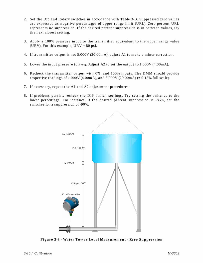
Figure 3-3 - Water Tower Level Measurement - Zero Suppression
M-3602 Calibration / 3-11
3.8.1 Zero Suppression Example (see Figure 3-3 & Table 3-B)
The full water tower of Figure 3-3, produces 53.5 psi of pressure due to the 125 foot head,i.e 10.7 psi plus 42.8 psi. To determine the Coarse Span Rotary Switch (SW1) setting,divide the pressure produced by the 25 feet of water in the tank by the Transmitter’srange; in this case 50 psi, i.e., 10.7/50 = 21.4%. Therefore, the SW1 should be set to position8 (18.5% - 23%).
To determine the zero suppression necessary for this example, divide the pressureproduced by 100 feet of water (height of tower to bottom of tank) by the Transmitter’srange; in this case 50 psi, i.e., 42.8/50 = 85.6%. With the Coarse Span Rotary Switch SW1set to its SW1-8 position, set the value of the Coarse Zero Switch (S1) to either -80%(00001100) or -90% (00001010), or to a binary value between the two e.g., 00001011 (-85%).Use Fine Adjustment Screw A2 to set 1.000V (4.00mA) @ 42.8 psi and use Fine AdjustmentScrew A1 to set 5.000V (20.00mA) @ 53.5 psi.
Note: When Zero Suppression is used, the maximum applied pressure may be upto 125% of the URL.
3.9 SELECTABLE DAMPING
The damping feature provides compensation for applications with severe pressurepulsation that cause the DC output of the transmitter to seem unstable. Controlling theresponse time of the transmitter output can minimize this condition. Do not use dampingwhen the application requires dynamic pressure measurement.
Jumper JP9 can be set to apply damping to the output. With jumper JP9 in place, thedamping is on. If the jumper does not connect the two pins together, the damping is off.
M-3602 Service / 4-1
Section 4SERVICE
4.1 GENERAL
Servicing should only be performed by technically competent persons skilled in the use ofpneumatic and electronic test equipment and having knowledge of troubleshootingprocedures.
After any service procedures are completed, the transmitter cover must be installed andproperly tightened. A failure to secure the cover will result in a loss of the enclosure's dust-tight, water-tight seal and explosion-proof rating.
WarningNo attempt should be made to service a transmitter while it is powered andoperating in a flammable or explosive environment. Either the area must bemade safe or the transmitter must be powered down, disconnected, and takento a safe, non-hazardous area.
4.2 TROUBLESHOOTING
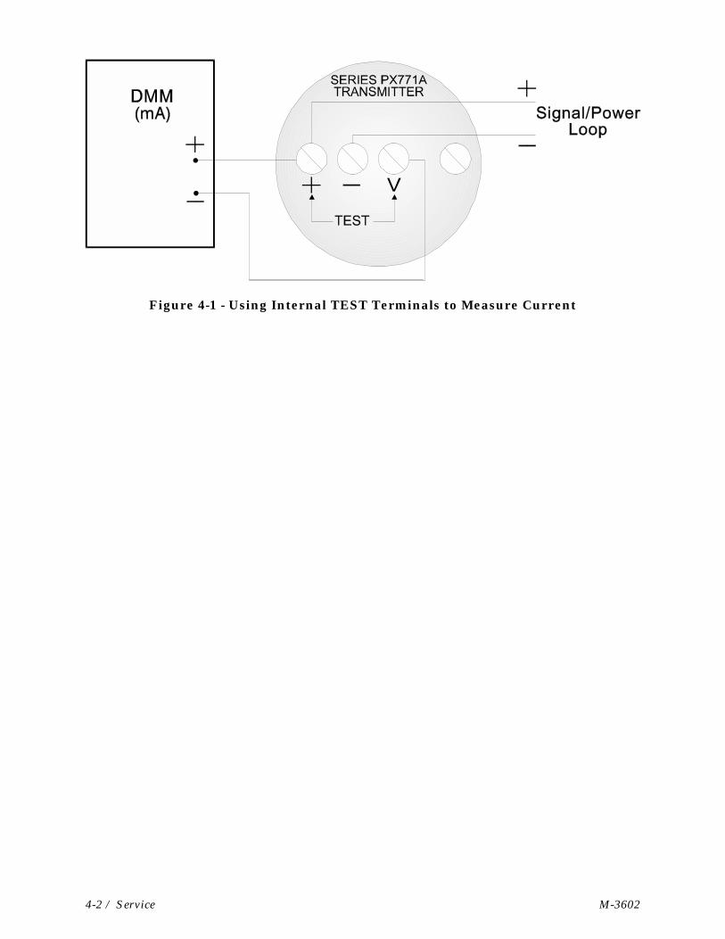
Some troubleshooting procedures will require that you use a digital multimeter (DMM) tomeasure the loop current. Connect the DMM across the V and (+) terminals of thetransmitter as shown in Figure 4-1 and set it to its "milliampere" function. This method ofconnection will not disturb the signal/power loop. The DMM reading will be proportional tothe input pressure and cover a range of 4-20 mA.
4.3 FACTORY REPAIRS
If you determine that a fault is present in the transmitter's PC board or pressure sensor, donot attempt any service as specialized factory equipment and test procedures will berequired. Defective transmitters may be returned to OMEGA for evaluation or repairs.Transmitters in warranty will be repaired or replaced per the warranty agreementcontained at the end of this manual.
4-2 / Service M-3602
Figure 4-1 - Using Internal TEST Terminals to Measure Current
M-3602 Specifications / 5-1
Section 5SPECIFICATIONS
NOTE: The specifications listed here are common to Series PX771A Transmittersdescribed in this manual.
5.1 FUNCTIONAL SPECIFICATIONS
Current Loop Mode:Supply Voltage 24.0 Vdc nominal
7.00 Vdc min. at transmitter10.0 Vdc min. with digital indicator option37.0 Vdc max. at transmitter42.0 Vdc with external load specifiedReverse polarity protection provided
Output 4-20 mA dc output, two wire analog (ISA 50.1Type, Class U2)Current limited to 28 mA max.Minimum current is 2 to 3.5 mA.
Voltage Mode:Supply Voltage 6-42 Vdc
Reverse polarity protected to 90 Vdc
Supply Current 1.6 mA nominal
Output 1-5 Vdc (3-wire)
Calibration Adjustments: Span Adjustment:Adj. Range is 16 to 100% URL.Coarse Span set by Rotary switch package.Fine Span set via 25-turn pot.
Zero Adjustment:Adj. range is -600 to 600% LRL for elevationand suppression.Coarse Zero provided by DIP switchselections. Fine Zero set via 25-turn pot.
Response Time & Damping: Time Constant:(Time required for 63% change in outputwith a 100% input change)Damping OFF ≅ 0.16 msDamping ON = 50 ms +20%
Damping:User selectable by jumper circuit

5-2 / Specifications M-3602
Recovery:Time to steady output after application of24 volt supply with constant pressure is 5ms maximum (With No Damping)
Linearity: On low-range models, full vacuum can representan appreciable percentage of URL. If, on thosemodels, calibration contains 50% of zeroelevation, non-linearity errors can be as high as+1%.
5.2 PERFORMANCE SPECIFICATIONS
Accuracy: (Includes independent linearity, hysteresis andrepeatability)+0.1% of calibrated span
Resolution: Virtually infinite
Long Term Stability: At constant conditions. +0.25% of URL/6 mo.
Ambient Temperature Effect: Total including Zero & Span+0.010% of URL per °F from -25 to 75 °F+0.015% of URL per °F from 75 to 185 °F+0.020% of URL per °F on 100 inH2O only
Power Supply Effect: + .005 %/Vdc
Ripple and Noise: In accordance with ISA 50.1, Section 4.6
5.3 ENVIRONMENTAL SPECIFICATIONS
Temperature Limits: Wet End using DC 200 Fill:-40 to 220 °F (-40 to 104 °C)*
Amplifier: -25 to 185 °F (-32 to 85 °C)
Digital Indicator:-22 to 158 °F (-30 to 70 °C)
Storage:-40 to 212 °F (-40 to 100 °C)
* The maximum permissible temperature insidethe enclosure (irrespective of sensor temperature)is 185 °F (85 °C) for the amplifier board, and 158°F (70 °C) for the digital indicator option.
M-3602 Specifications / 5-3
Humidity Limits: Specified with transmitter electronichousing cover installed.15-95% RH to 140 °F (60 °C)15-50% RH to 185 °F (85 °C)
EMI Effect: +1% of URL @ 10 V/M, 20 MHz to 500 MHz
Meets /SAMA PMC-33-1C with transmittercover in place and all wiring contained ingrounded conduit.
Surge Protection: Bipolar, differential surge
1000 watts for 1 ms (without digitalindicator option)
May be used with purchased surge protectorfor additional protection (for non-hazardous,non-approved installations only).
Vibration Effect: Less than +0.1% of URL for 10 to 500 Hz at1 g on any axis. Meets SAMA PMC-31-1
5.4 PHYSICAL SPECIFICATIONS
Fill Media: DC 200 Silicone
Electronics Housing: Low copper aluminum, epoxy finish, NEMA4X rating
Electrical Connections: 1/2 NPT conduit connection with internalfield wiring terminals.
05/08/2001 Appendix A of M3602 Page 1 of 1
Series PX771A TransmitterSpecial Instructions for Class I, Division 2 Hazardous Locations
1. The OMEGA Series PX771A Differential Pressure Transmitter is listed by Under-writers Laboratories (UL) as nonincendive and are suitable for use in Class I, Division2, Groups A, B, C and D hazardous locations or non-hazardous locations. Read thisdocument carefully before installing a nonincendive OMEGA Series PX771A PressureTransmitter. In the event of a conflict between the Series PX771A Instruction Manual(M-3602) and this document, always follow the instructions in this document.
2. Wiring must be performed in accordance with Class I, Division 2 wiring methods asdefined in Article 501-4 (b) of the National Electrical Code, NFPA 70 for installationswithin the United States, or as specified in Section 18-152 of the Canadian ElectricalCode for installation in Canada.
3. Model equipped with the Loop Powered Indicator Option (Appendix B) are approved foruse in Class I, Division 2, Groups A, B, C and D hazardous locations.
4. WARNING: EXPLOSION HAZARD - Substitution of components may impairsuitability for use in Class I, Division 2 environments.
5. WARNING: EXPLOSION HAZARD - When situated in a hazardous location,turn off power before servicing/replacing the unit and before installing orremoving I/O wiring.
6. WARNING: EXPLOSION HAZARD - Do Not disconnect equipment unless thepower has been switched off or the area is known to be nonhazardous.

Appendix B
For
Series PX771A
Differential Pressure Transmitters
For
Series PX771A
Differential Pressure Transmitters
LOOP POWERED INDICATOR OPTION
Operator's ManualM-3602/1101 - Appendix BOperator's ManualM-3602/1101 - Appendix B
R
R
R
R
R
R
R
R
R
R
R
R
R
R
R
R
MER
An OMEGA Technologies CompanyAn OMEGA Technologies Company
TB21
PSI
M3602/1101 Appendix B Page 0-1 Table Of Contents
Appendix BLOOP POWERED INDICATOR OPTION
TABLE OF CONTENTS
SECTION TITLE
Section 1 - INTRODUCTION
1.1 INTRODUCTION .............................................................................................................. 11.1.1 Features............................................................................................................................... 11.1.2 Hardware Circuit Overview................................................................................................ 11.1.3 Adjustments ........................................................................................................................ 21.1.4 Connectors .......................................................................................................................... 2
Section 2 - INSTALLATION, OPERATION & SERVICE
2.1 INSTALLATION & REMOVAL/REPLACEMENT OF THE LPI................................... 32.1.1 Installation/Removal of the Loop Powered Indicator......................................................... 32.2 FIELD WIRING ................................................................................................................. 72.3 OPERATIONAL DETAILS............................................................................................... 72.3.1 Configuring the Loop Powered Indicator ........................................................................... 72.3.2 Accuracy and Decimal Point Settings .............................................................................. 102.3.3 Displaying Current Using the LPI .................................................................................... 102.3.4 Error Conditions ............................................................................................................... 112.3.4.1 Conversion and Display Error Conditions........................................................................ 112.4 SERVICE.......................................................................................................................... 11
Section 3 - SPECIFICATIONS
3.1 ENVIRONMENTAL SPECIFICATIONS ....................................................................... 12
Appendix B Page 1 Loop Powered Indicator
Section 1INTRODUCTION
1.1 INTRODUCTION
The loop powered indicator (LPI) option is used to provide local indication in engineeringunits of the measurand represented by a 4-20 mA current loop. The LPI may be installed ina Series PX725A, PX726A or PX771A Transmitter with the Display Cover Assembly or in astand-alone housing. The LPI is powered by the 4-20 mA current loop using less than 500uA @ 3 V for the electronic circuitry.
The LPI option is a circuit board assembly with a micro-controller, a liquid-crystal display(LCD) and active electronic circuitry contained on a single board, i.e., the “Meter/DisplayBoard.” The Meter/Display Board plugs into the “Meter Motherboard” that provides theelectrical connections from the transmitter interface and allows the display to be rotated in90-degree increments.
1.1.1 Features
• Powered by a 4-20 mA current loop using less than 500 uA @ 3V• Dual Board Set - Meter Motherboard allows the Meter/Display Board to be rotated in
90-degree increments.• 4½ Digit Display allows display of numeric values as large as 19999.• Eight selectable unit labels: mA, %, psi, IN H2O, bar, kg/cm2, °C, and °F.• One selectable “no-label” position.• Reverse polarity protection.• Over current protection
1.1.2 Hardware Circuit Overview
The LPI option uses a micro-controller with integral LCD display drivers. The currentflowing through the LPI is sampled and converted to a corresponding digital word. Basedon user-configuration the digital value is displayed in engineering units along with a unitlabel.
The 4½ digit display can show numeric values as large as 19999. The display contains eightintegral unit labels. These are: mA, %, psi, IN H2O, bar, kg/cm2, °C, and °F.
Calibration is done at the board level by injecting known current levels into the assembly,reading the current and computing correction coefficients that are then stored in the LPI.The coefficients are then used in a correction algorithm to linearize the current signal andachieve a minimum accuracy of 0.1%FS at room temperature. The circuit uses precisionresistors to sample the current. The Meter/Display Board is burned-in for long-termstability and reliability. Operating temperature is limited by the LCD display to -30 to +70°C. Calibration is done once at the factory, but unit display selection may be done as oftenas required by the user (see Section 2.3.1).
Reverse polarity protection is achieved by shunting the entire circuit with a diode. A 250mA fuse provides overcurrent protection. A shunt capacitor is also included to minimizeEMI effects and provide secondary transient protection.

Loop Powered Indicator Page 2 Appendix B
The two-board assembly is designed for field retrofit in Series PX725A, PX726A andPX771A pressure transmitters.
1.1.3. Adjustments
Adjustment potentiometers are unnecessary in the LPI. The indicator is always scaled to 4-20mA. The user configures the LPI in engineering units of their choice, i.e., mA, %, psi, INH2O, bar, kg/cm2, °C, °F or Custom.
1.1.4 Connectors
The LPI Assembly comes in two parts: The Meter Motherboard and the Meter/DisplayBoard. The Meter Motherboard is assembled into the Series PX725A, PX726A or PX771ATransmitter by connecting the transmitter’s terminal block to the spade fingers integral tothe Meter Motherboard and installing the mounting screws through the MeterMotherboard to the cast-in mounting bosses in the transmitter housing. The customer cableis then connected to the compression-type terminals of Terminal Block TB1 on the MeterMotherboard. Finally, the Meter/Display Board plugs into the Meter Motherboard in anyone of four positions depending on the desired meter rotation; this is through a set of two-conductor “Berg” connectors. The Meter/Display Board is also secured to the MeterMotherboard with four screws.
Figure 1-1 - PX725A, PX726A or PX771A Transmitterwith Loop Powered Indicator
Appendix B Page 3 Loop Powered Indicator
Section 2INSTALLATION, OPERATION & SERVICE
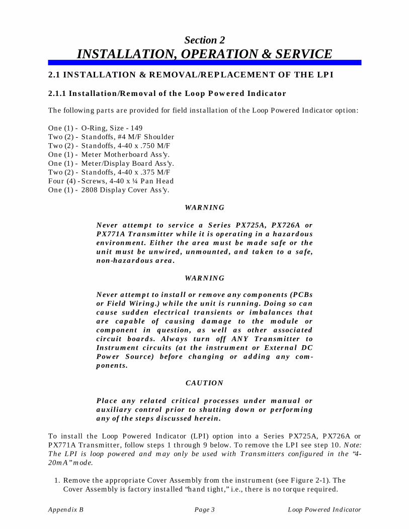
2.1 INSTALLATION & REMOVAL/REPLACEMENT OF THE LPI
2.1.1 Installation/Removal of the Loop Powered Indicator
The following parts are provided for field installation of the Loop Powered Indicator option:
One (1) - O-Ring, Size - 149Two (2) - Standoffs, #4 M/F ShoulderTwo (2) - Standoffs, 4-40 x .750 M/FOne (1) - Meter Motherboard Ass’y.One (1) - Meter/Display Board Ass’y.Two (2) - Standoffs, 4-40 x .375 M/FFour (4) - Screws, 4-40 x ¼ Pan HeadOne (1) - 2808 Display Cover Ass’y.
WARNING
Never attempt to service a Series PX725A, PX726A orPX771A Transmitter while it is operating in a hazardousenvironment. Either the area must be made safe or theunit must be unwired, unmounted, and taken to a safe,non-hazardous area.
WARNING
Never attempt to install or remove any components (PCBsor Field Wiring.) while the unit is running. Doing so cancause sudden electrical transients or imbalances thatare capable of causing damage to the module orcomponent in question, as well as other associatedcircuit boards. Always turn off ANY Transmitter toInstrument circuits (at the instrument or External DCPower Source) before changing or adding any com-ponents.
CAUTION
Place any related critical processes under manual orauxiliary control prior to shutting down or performingany of the steps discussed herein.
To install the Loop Powered Indicator (LPI) option into a Series PX725A, PX726A orPX771A Transmitter, follow steps 1 through 9 below. To remove the LPI see step 10. Note:The LPI is loop powered and may only be used with Transmitters configured in the “4-20mA” mode.
1. Remove the appropriate Cover Assembly from the instrument (see Figure 2-1). TheCover Assembly is factory installed “hand tight,” i.e., there is no torque required.

Loop Powered Indicator Page 4 Appendix B
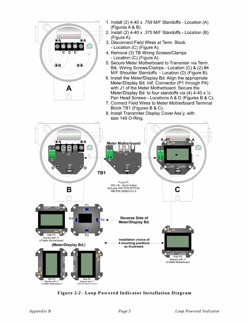
2. Referring to Figure 2-2, install the two (2) 4-40 x .759 Standoffs into the Transmitterat location A.
Figure 2-1 - Transmitter Cover Assembly Removal
3. Referring to Figure 2-2, install the two (2) 4-40 x .375 Standoffs into the Transmitter atlocation B.
4. Disconnect the Field Wires (if installed) from the Transmitter’s Terminal Block.
5. Remove the three (3) Field Wiring Screws/Clamps from the Transmitter’s TerminalBlock.
6. Secure the Meter Motherboard to the Transmitter via the three (3) Field WiringScrews/Clamps removed in step 5. Using two (2) #4 M/F Shoulder Standoffs, secure theMotherboard to the Standoffs installed in step 3.
7. Install the Meter/Display Board onto the Meter Motherboard after aligning the ap-propriate Meter/Display Board Interface Connector (P1 through P4) with J1 of theMeter Motherboard. Secure the Meter/Display Board to the four standoffs (Locations A& D of Figure 2-2) via four (4) 4-40 x ¼ Pan Head Screws.
Appendix B Page 5 Loop Powered Indicator
Figure 2-2 - Loop Powered Indicator Installation Diagram

Loop Powered Indicator Page 6 Appendix B
8. Connect the field wires to the compression-type terminals of Meter MotherboardTerminal Block TB1 (see Section 2.2 & Figure 2-5). Configure the LPI for operation(see Section 2.3.1).
9. Install the Transmitter Display Cover Assembly (with size 149 O-Ring) onto theTransmitter (see Figures 2-3 & 2-4). Lubricate O-Ring with Dow Corning SiliconeGrease (Compound 4) or equivalent prior to assembly. Lubricate threads with“NEVER-SEEZ” “Pure Nickel Special” or equivalent prior to assembly. Tighten untilCover contacts the Transmitter Housing (no torque required).
Figure 2-3 – Series PX725A, PX726A & PX771A Display Cover Assembly
Figure 2-4 - Transmitter with Loop Powered Indicator Option Installed
Appendix B Page 7 Loop Powered Indicator
10. To remove the LPI Option from a Series PX725A, PX726A or PX771A Transmitter,follow steps 7 through 9 in reverse order, removing rather than installing the item inquestion.
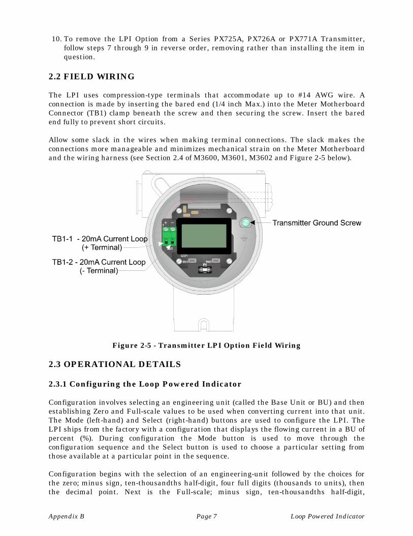
2.2 FIELD WIRING
The LPI uses compression-type terminals that accommodate up to #14 AWG wire. Aconnection is made by inserting the bared end (1/4 inch Max.) into the Meter MotherboardConnector (TB1) clamp beneath the screw and then securing the screw. Insert the baredend fully to prevent short circuits.
Allow some slack in the wires when making terminal connections. The slack makes theconnections more manageable and minimizes mechanical strain on the Meter Motherboardand the wiring harness (see Section 2.4 of M3600, M3601, M3602 and Figure 2-5 below).
Figure 2-5 - Transmitter LPI Option Field Wiring
2.3 OPERATIONAL DETAILS
2.3.1 Configuring the Loop Powered Indicator
Configuration involves selecting an engineering unit (called the Base Unit or BU) and thenestablishing Zero and Full-scale values to be used when converting current into that unit.The Mode (left-hand) and Select (right-hand) buttons are used to configure the LPI. TheLPI ships from the factory with a configuration that displays the flowing current in a BU ofpercent (%). During configuration the Mode button is used to move through theconfiguration sequence and the Select button is used to choose a particular setting fromthose available at a particular point in the sequence.
Configuration begins with the selection of an engineering-unit followed by the choices forthe zero; minus sign, ten-thousandths half-digit, four full digits (thousands to units), thenthe decimal point. Next is the Full-scale; minus sign, ten-thousandths half-digit,
Loop Powered Indicator Page 8 Appendix B
thousandths to units, and decimal point. The final press of the Mode button causes an exitfrom configuration mode to run mode. At any point in the sequence pressing the Modebutton selects the next item in the order i.e., to leave a previously configured item as is,press Mode to skip over it. When configuration is started a one-minute timer is loaded; it isreloaded whenever a Mode or Select button is pressed. If no button activity occurs for oneminute the timer will expire and restore the previously active configuration.
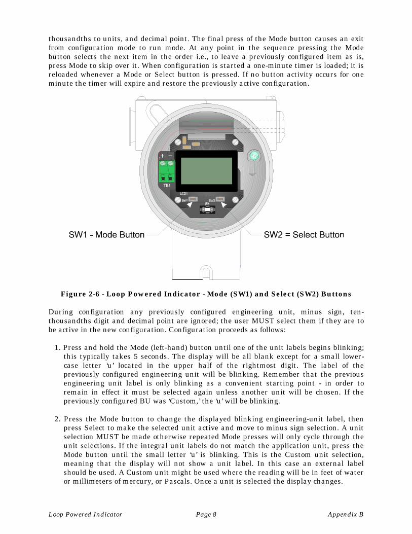
Figure 2-6 - Loop Powered Indicator - Mode (SW1) and Select (SW2) Buttons
During configuration any previously configured engineering unit, minus sign, ten-thousandths digit and decimal point are ignored; the user MUST select them if they are tobe active in the new configuration. Configuration proceeds as follows:
1. Press and hold the Mode (left-hand) button until one of the unit labels begins blinking;this typically takes 5 seconds. The display will be all blank except for a small lower-case letter ‘u’ located in the upper half of the rightmost digit. The label of thepreviously configured engineering unit will be blinking. Remember that the previousengineering unit label is only blinking as a convenient starting point - in order toremain in effect it must be selected again unless another unit will be chosen. If thepreviously configured BU was ‘Custom,’ the ‘u’ will be blinking.
2. Press the Mode button to change the displayed blinking engineering-unit label, thenpress Select to make the selected unit active and move to minus sign selection. A unitselection MUST be made otherwise repeated Mode presses will only cycle through theunit selections. If the integral unit labels do not match the application unit, press theMode button until the small letter ‘u’ is blinking. This is the Custom unit selection,meaning that the display will not show a unit label. In this case an external labelshould be used. A Custom unit might be used where the reading will be in feet of wateror millimeters of mercury, or Pascals. Once a unit is selected the display changes.
Appendix B Page 9 Loop Powered Indicator
If the selected unit is mA or % no further configuration is allowed and configurationmode ends. For other units the following occurs.
The SET LO legend appears with the minus sign blinking, and the previously con-figured digits for the Zero appear without a decimal point. Previously configured minussign and ten-thousandths half-digit choices are cancelled, and new selections must bemade. Press Select to make the minus active, press Mode to skip over it. The ten-thousandths digit (a one) begins blinking after the minus sign has been configured.Again, press Select to make it active, press Mode to skip over it.
After the ten-thousandths digit is selected the thousands (leftmost) full digit will beginblinking.
3. Press the Select button to increment the digit (zero to nine) or press Mode to leave thedigit as it is and activate the next digit location to the right. Repeat until all digitshave been set.
When Mode is pressed while the units (rightmost) digit location is blinking decimalpoint locations 2 and 5 will start blinking. As with units, a selection MUST be made orthe Mode button will just cycle through all decimal point choices. When decimal pointlocations 2 and 5 are blinking simultaneously this indicates a “no decimal” choice,meaning that the decimal point is “hidden” on the far right of the display.
4. Press the Mode button to display the next decimal point choice, which will be thelocation to the left of the rightmost digit. As the Mode button is pressed the blinkingdecimal point will shift to the left in the display and eventually wrap-around to repeatthe simultaneous display of locations 2 and 5. Press the Select button to make theblinking decimal point location active and move to the configuration of Full-scale.
When the Zero decimal point is selected the SET LO legend will disappear and the SETHI legend will appear. The minus sign location will be blinking, and the digit locationswill contain previously configured Full-scale values.
5. Use the Mode and Select buttons to configure the minus sign, ten-thousandths digit,thousandths to units, and decimal point. When the decimal point is selectedconfiguration is complete. The SET HI legend will disappear, blinking will stop and theunit will exit Configuration mode and enter Run mode.
6. Upon exit from configuration mode the selected configuration (Base Unit, BU) is storedin an EEPROM where it remains until another configuration occurs. Current is alwaysconverted to and displayed in the selected BU henceforth.
If the selected unit is mA or % only the unit selection itself is stored.
If the selected unit is one of the four pressure units (psi, inH2O, bar, kg/cm2) then thezero and full scale of the other pressure units are converted to be proportional to theBU and then stored. This means that the zero and full scale of a selected BU of psi areconverted to the other pressure units and saved along with the BU zero and full scale.
If the selected BU is one of the two temperature units (Celsius, Fahrenheit) then theother temperature unit zero and full scale are converted and then saved.
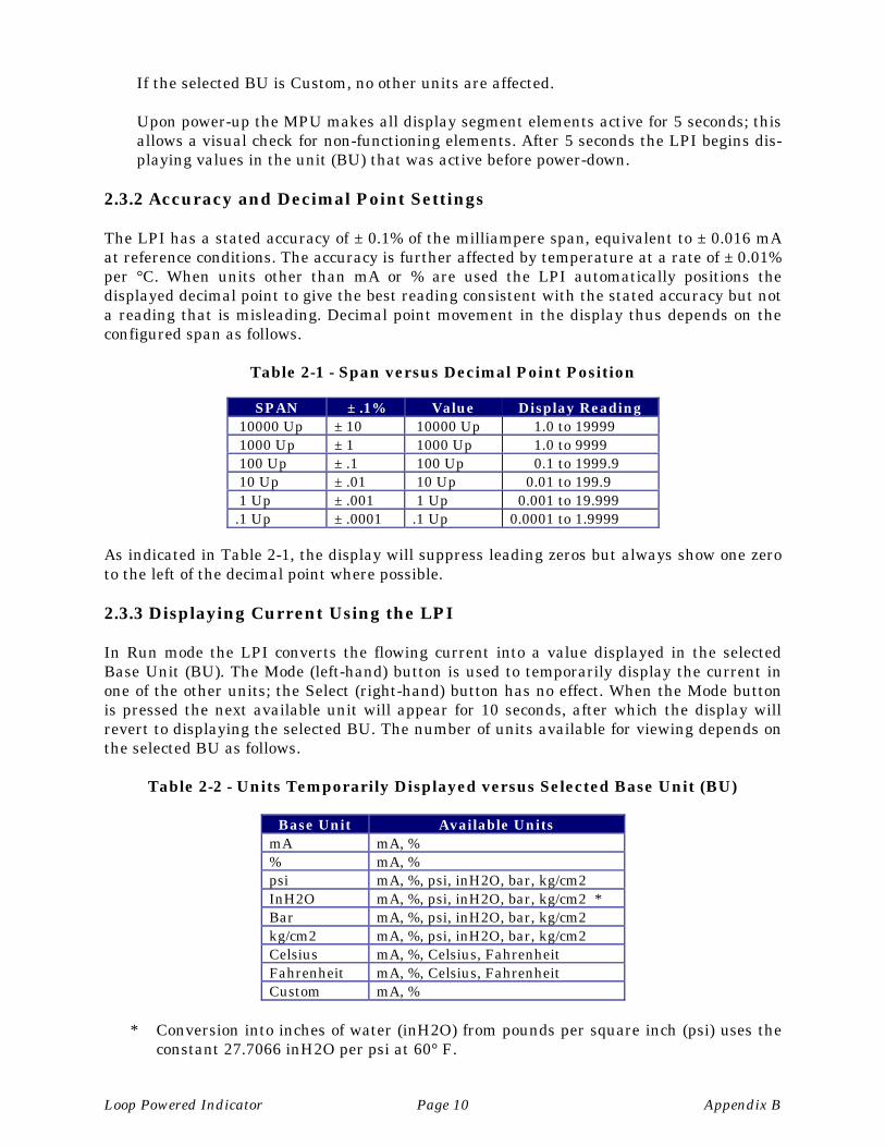
Loop Powered Indicator Page 10 Appendix B
If the selected BU is Custom, no other units are affected.
Upon power-up the MPU makes all display segment elements active for 5 seconds; thisallows a visual check for non-functioning elements. After 5 seconds the LPI begins dis-playing values in the unit (BU) that was active before power-down.
2.3.2 Accuracy and Decimal Point Settings
The LPI has a stated accuracy of ± 0.1% of the milliampere span, equivalent to ± 0.016 mAat reference conditions. The accuracy is further affected by temperature at a rate of ± 0.01%per °C. When units other than mA or % are used the LPI automatically positions thedisplayed decimal point to give the best reading consistent with the stated accuracy but nota reading that is misleading. Decimal point movement in the display thus depends on theconfigured span as follows.
Table 2-1 - Span versus Decimal Point Position
SPAN ± .1% Value Display Reading 10000 Up ± 10 10000 Up 1.0 to 19999 1000 Up ± 1 1000 Up 1.0 to 9999 100 Up ± .1 100 Up 0.1 to 1999.9 10 Up ± .01 10 Up 0.01 to 199.9 1 Up ± .001 1 Up 0.001 to 19.999.1 Up ± .0001 .1 Up 0.0001 to 1.9999
As indicated in Table 2-1, the display will suppress leading zeros but always show one zeroto the left of the decimal point where possible.
2.3.3 Displaying Current Using the LPI
In Run mode the LPI converts the flowing current into a value displayed in the selectedBase Unit (BU). The Mode (left-hand) button is used to temporarily display the current inone of the other units; the Select (right-hand) button has no effect. When the Mode buttonis pressed the next available unit will appear for 10 seconds, after which the display willrevert to displaying the selected BU. The number of units available for viewing depends onthe selected BU as follows.
Table 2-2 - Units Temporarily Displayed versus Selected Base Unit (BU)
Base Unit Available UnitsmA mA, %% mA, %psi mA, %, psi, inH2O, bar, kg/cm2InH2O mA, %, psi, inH2O, bar, kg/cm2 *Bar mA, %, psi, inH2O, bar, kg/cm2kg/cm2 mA, %, psi, inH2O, bar, kg/cm2Celsius mA, %, Celsius, FahrenheitFahrenheit mA, %, Celsius, FahrenheitCustom mA, %
* Conversion into inches of water (inH2O) from pounds per square inch (psi) uses theconstant 27.7066 inH2O per psi at 60° F.
Appendix B Page 11 Loop Powered Indicator
As the Mode button is pressed the display will change to the next available unit in the ordershown above starting with the BU. With a BU of inH2O for example, the order would bebar, kg/cm2, mA, %, psi, then back to inH2O.
2.3.4 Error Conditions
LPIs that have not been factory calibrated will alternately show a reading and UCUC (forUncalibrated) in the display for four seconds. Customers should never see this indicationunless the EEPROM has completely lost its contents.
The LPI reads an EPROM checksum every second and compares it to a checksumcalculated on the RAM area holding the data read from the EEPROM. If there is adifference the EEPROM is reread and the checksums are tested again.
An invalid checksum causes a reset and reread, during which the display will show ablinking EErr message. Reset occurs every 250 milliseconds.
If a write of the EEPROM (only occurs during configuration or calibration) fails because theEEPROM did not acknowledge the write the same EErr message is displayed but is notblinking because the LPI has been halted on the condition of the failure.
2.3.4.1 Conversion and Display Error Conditions
During operation three error conditions can occur that cause “dashes” to be displayed.
The first is a “cannot display” condition that can occur when the number to be shown is toolarge to fit in the LCD display. This can occur, for example, if the Full-scale value was setas 19,999 (equivalent to 20 mA). When the input current exceeds 20 mA a value of 20,000 orlarger cannot be displayed – in this case the display will show four dashes “----“.
The second and third conditions occur when the input current has exceeded the validconversion range and a numeric display value would be meaningless and possiblymisleading. If the current exceeds 21.6 mA to the point where internal conversions are notvalid the display will show two “dashes” right-justified in the display e.g., “ --“. If currentdrops below 2.4 mA to the point where internal conversions are not valid then two left-justified “dashes” are displayed e.g., “-- “.
2.4 SERVICE
Series PX725A, PX726A & PX771A Loop Powered Indicators are equipped with a 250 mAQuick Acting Fuse (F1) that is situated on the Meter Motherboard Assembly. Check thefollowing items if Loop Powered Indicator operation is faulty:
1. Check wiring at TB1 of the Meter Motherboard.2. Check field wiring at the field device.3. Check Fuse F1 and replace it if it is defective (see Figure 2-2).4. Make sure that the Meter Motherboard is properly secured to the transmitter.5. Make sure that the Meter/Display Board is properly mated with the Meter Mother-
board.
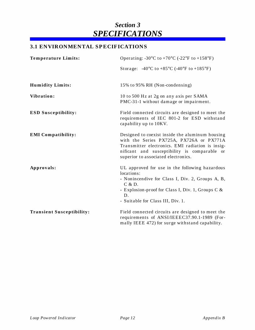
Loop Powered Indicator Page 12 Appendix B
Section 3SPECIFICATIONS
3.1 ENVIRONMENTAL SPECIFICATIONS
Temperature Limits: Operating: -30°C to +70°C (-22°F to +158°F)
Storage: -40°C to +85°C (-40°F to +185°F)
Humidity Limits: 15% to 95% RH (Non-condensing)
Vibration: 10 to 500 Hz at 2g on any axis per SAMA PMC-31-1 without damage or impairment.
ESD Susceptibility: Field connected circuits are designed to meet therequirements of IEC 801-2 for ESD withstandcapability up to 10KV.
EMI Compatibility: Designed to coexist inside the aluminum housingwith the Series PX725A, PX726A or PX771ATransmitter electronics. EMI radiation is insig-nificant and susceptibility is comparable orsuperior to associated electronics.
Approvals: UL approved for use in the following hazardouslocations:- Nonincendive for Class I, Div. 2, Groups A, B,
C & D.- Explosion-proof for Class I, Div. 1, Groups C &
D.- Suitable for Class III, Div. 1.
Transient Susceptibility: Field connected circuits are designed to meet therequirements of ANSI/IEEEC37.90.1-1989 (For-mally IEEE 472) for surge withstand capability.

11/27/00 Appendix Z - M-3602 MSDS
Series PX771A TransmittersMaterial Safety Data Sheets
Material Safety Data Sheets are provided herein to comply with OSHA’s HazardCommunication Standard, 29 CFR 1910.1200. This standard must be consulted for specificrequirements.
Material Safety Data Sheets are provided in the order listed in Table Z-1 below.
TABLE Z-1 - MSDS for Series PX771A Transmitters Instruction Manual M-3602
Manufacturer General Description OMEGA ENGINEERINGPart Number or Media Notes
Dow Corning Silicone 200(R) Fluid,100 CST
Pressure Transducer Media Fill
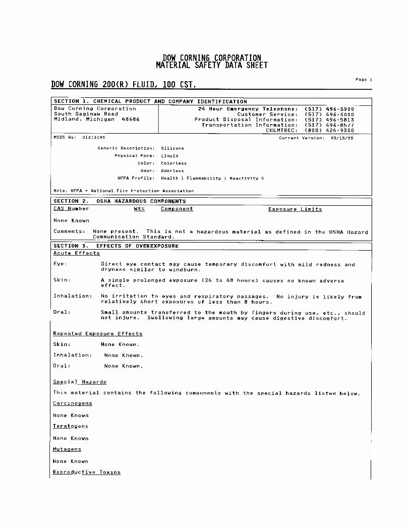
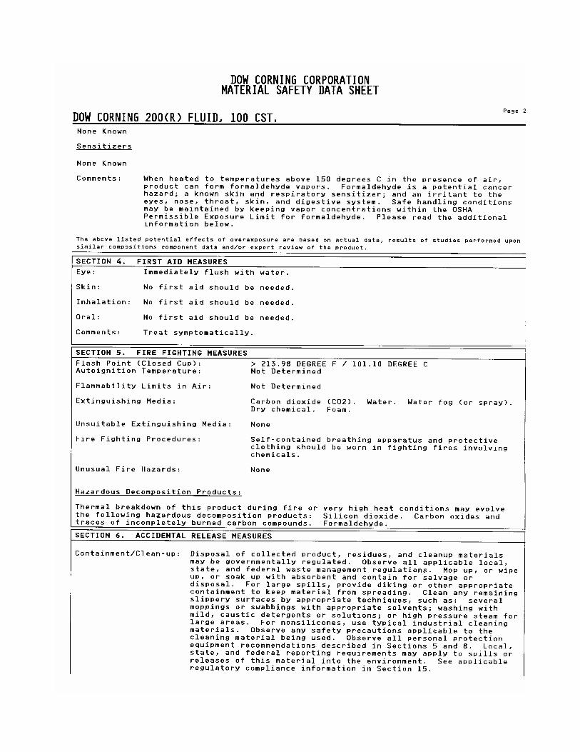
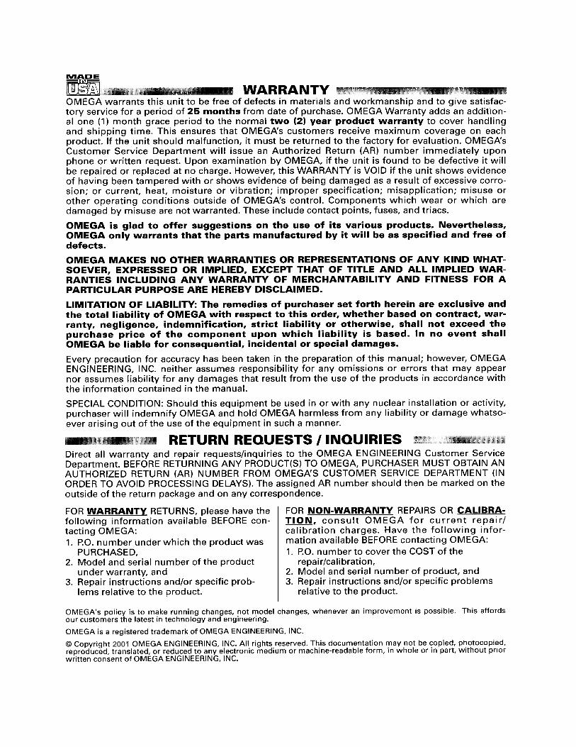
2001

![SPair-71k: A Large-scale Benchmark for Semantic ...arXiv:1908.10543v1 [cs.CV] 28 Aug 2019 Type View-point diff. Scale diff. Truncation diff. Occlusion diff. easy medi hard easy medi](https://img.pdfslide.us/doc/110x75/6049bbd3adaaa52b560671c6/spair-71k-a-large-scale-benchmark-for-semantic-arxiv190810543v1-cscv-28.jpg)