Embed Size (px)
DESCRIPTION
Marine engine repair- how to- This help me, to understood marine engines troubleshooting
Citation preview


PAT MANLEY
Diesels Afl oat


DieselsAfl oat


PAT MANLEY
Diesels Afl oat

Copyright © 2007 John Wiley & Sons Ltd
Published under the Fernhurst imprint by John Wiley & Sons Ltd, The Atrium, Southern Gate, Chichester, West Sussex PO19 8SQ, England
Telephone (�44) 1243 779777
Email (for orders and customer service enquiries): [email protected] our Home Page on www.wiley.com
All Rights Reserved. No part of this publication may be reproduced, stored in a retrieval system or transmitted in any form or by any means, electronic, mechanical, photocopying, recording, scanning or otherwise, except under the terms of the Copyright, Designs and Patents Act 1988 or under the terms of a licence issued by the Copyright Licensing Agency Ltd, 90 Tottenham Court Road, London W1T 4LP, UK, without the permission in writing of the Publisher. Requests to the Publisher should be addressed to the Permissions Department, John Wiley & Sons Ltd, The Atrium, Southern Gate, Chichester, West Sussex PO19 8SQ, England, or emailed to [email protected], or faxed to (�44) 1243 770620.
Designations used by companies to distinguish their products are often claimed as trademarks. All brand names and product names used in this book are trade names, service marks, trademarks or registered trademarks of their respective owners. The Publisher is not associated with any product or vendor mentioned in this book.
This publication is designed to provide accurate and authoritative information in regard to the subject matter covered. It is sold on the understanding that the Publisher is not engaged in rendering professional services. If professional advice or other expert assistance is required, the services of a competent professional should be sought.
Other Wiley Editorial Offi ces
John Wiley & Sons Inc., 111 River Street, Hoboken, NJ 07030, USA
Jossey-Bass, 989 Market Street, San Francisco, CA 94103-1741, USA
Wiley-VCH Verlag GmbH, Boschstr. 12, D-69469 Weinheim, Germany
John Wiley & Sons Australia Ltd, 42 McDougall Street, Milton, Queensland 4064, Australia
John Wiley & Sons (Asia) Pte Ltd, 2 Clementi Loop #02-01, Jin Xing Distripark, Singapore 129809
John Wiley & Sons Canada Ltd, 6045 Freemont Blvd, Mississauga, ONT, L5R 4J3
Wiley also publishes its books in a variety of electronic formats. Some content that appears in print may not be available in electronic books.
Index compiled by Alan Thatcher
Anniversary Logo Design: Richard J. Pacifi co
Library of Congress Cataloguing in Publication Data
Manley, Pat. Diesels afl oat / Pat Manley. p. cm. Includes bibliographical references and index. ISBN: 978- 0 -470- 06176- 3 (pbk. : alk. paper) 1. Marine diesel motors. I. Title. VM770.M347 2007 623.87´236—dc22 2006038742
British Library Cataloguing in Publication Data
A catalogue record for this book is available from the British Library
ISBN 978-0-470-06176-3 (PB)
Typeset in 9/12 pt Swiss 721 by Thomson DigitalPrinted in Italy by Printer Trento, TrentoThis book is printed on acid-free paper responsibly manufactured from sustainable forestryin which at least two trees are planted for each one used for paper production.

Preface ix
Introduction xi
1. The Diesel Engine 1How it all started 1The modern diesel engine 2Getting the power to the prop 4Compression ignition 9The four stroke cycle 10Multi-cylinder engines 13Turbo-charging 13Super-charging 18The two-stroke diesel engine 19Injecting the fuel 21Cold starting 26Valve gear 29Decompressors 31Diesel engine speed control 32Smoke in the exhaust 35Cylinder bore glazing 39Engine power 43Fuel consumption 48Operation of the engine 49Read the book 49Where it’s all going 50
2. The Fuel System 51The fuel tank 51Primary filter 55Fuel lift pump 57Engine fine filter 63Fuel injection pump 65
Contents
v
CONTENTS
vi
Fuel injectors 66Removing air from the fuel system 68Starting and stopping the engine 70Biological contamination of fuel 72Winterisation of the fuel system 74
3. The Engine Cooling System 77Air cooling 77Water cooling 77Water flow failure 82Seawater (raw water) pump 82Sabb water pump 91Freshwater circulating pump 91Heat exchangers 92Syphon break 96The thermostat 99Anodes 103Water strainers 105Water injection bend 108Dry riser 109Antifreeze 109Water-logged engine 110Draining and refilling the cooling system 112
4. Lubrication 117The sump (oil pan) 117The strainer 118The oil pump 118Pressure relief valve 119The oil filter 119Crankcase breather 120Engine lubricating oil 121
5. The Air System 127The air filter/silencer 130The exhaust 131
6. Engine Electrics 133Typical engine electrics block diagrams 133Engine-driven 12-volt DC alternator 139Starter motor 150Dynastart 156Batteries 157
7. The Gearbox 169Speed reduction 169Forward and astern 170Neutral 170Gearwheels 170Types of grearbox 170Lubrication 175

CONTENTS
vii
Maintenance 175Troubleshooting 176
8. Drive Belts 179Adjusting the tension 179Measuring the tension 180Short belt life 181
9. Throttle and Gear Selection 183Twin-lever systems 183Single-lever controls 184Dual-station systems 186Electronic systems 187Operating cables 188Maintenance of throttle and gear selectors 190
10. Electronic Engine Management 197What is electronic engine management? 197Troubleshooting 200
11. Propellers 203Introduction 203A propeller 203How does a propeller work? 204Slip 205Efficiency 205Thrust 206Fixed pitch propellers 210Water flow past the propeller 210Doing the sums 211Propeller overview 212Conclusion 220
12. Prevention of Faults 223
13. Troubleshooting 225Engine won’t start 225No response to throttle 232No response to gear selection 232No water from exhaust 234Engine overheat alarm operates 235Engine low oil pressure alarm operates 236Alternator/generator warning light illuminates 236
14. Maintenance 239Engine servicing 239Adjusting the valve clearance 248Engine mounts 253
15. Winterisation 257Fuel tank 257Servicing 257Cooling system 257

CONTENTS
viii
Air system 258Electrics 259Cleanliness 259Ventilation and heating 260If the boat is to be laid up out of the water 260
16. Recommissioning 261Horizontal alignment 261Checking angular and vertical alignment 262
17. Engine Compartment Fire Extinguishers 267The causes of fire in engine compartments 267Fire detection 267Types of extinguisher 268Different types of system 269Automatic operation 271My system 272
18. Tools 273Engine tools 273Engine spares and consumables 274
Index 277
Picture Credits 287

In 2005, The UK’s RNLI lifeboats were launched 8421 times for all causes. Of these, 1710 launches were to vessels suffering machinery failure, 1298 being to lei-sure craft (387 of these were sailing vessels and 911 were power craft). These numbers don’t include fail-ures dealt with by professional breakdown services or friendly tows.
Some knowledge of the operation of diesel engines and their systems, their maintenance and the abil-ity to carry out simple repairs would have reduced the need for the rescue services to attend these craft signifi cantly.
The RYA’s desire to improve this situation led to the introduction of the RYA Diesel Engine Course in 1996, and I became one of its earliest instructors. Diesels Afl oat incorporates much of the feedback from yachts-men who have attended my RYA Diesel Engine courses since their inception, and covers the complete syllabus in depth. It answers the questions that I’m asked most frequently and which aren’t answered in other books. However, there’s much additional information that I consider essential for a proper understanding of a die-sel engine’s working and its operation by the skipper.
Troubleshooting is often covered by tables giving no defi nitive answer. I believe that a proper understanding
Preface
ix

PREFACE
x
of the diesel engine makes these tables superfl uous and instead use the much more helpful descriptive text combined with a proper understanding of the various systems.
A boat’s engine cannot be considered alone. There’s a need to convert its power to propel the boat and this part of the system is often considered a black art. As I am often being asked about propellers, both by stu-dents and Practical Boat Owner magazine readers, I have devoted a chapter to this subject.
Pat Manley

During the 1930s, with the increasing popularity of sailing cruising yachts as a leisure pursuit, fi tting an auxiliary engine became common. The unwillingness of these small petrol engines to start, and their general unreliability, meant that their use tended to be confi ned to occasions when there was no wind, and even then, many yachtsmen sailed as if they had no engine. They were, in all senses of the word, auxiliary engines and were hated and distrusted by many yachtsmen.
As auxiliary engines became more common, a rule of thumb developed such that their size for any given yacht was about 2 horsepower for every ton of dis-placement. This was adequate for getting home when the wind was too light to sail, but was not too much use for battling into wind and sea. But as it was a sail-ing boat after all, that did not matter.
When small, reliable marine diesel engines became available in the 1960s, coupled with the need to get home to go to work, engine powers were increased, such that 4 horsepower per ton of displacement be-came the norm. This allowed sailing boats to be mo-tored into wind and wave and make progress, and in calm water they could achieve their maximum ‘hull’ speed. That is, they could go as fast as was economi-cally sensible under power. Displacement motorboats could use the same rule of thumb, but as they had no
Introduction
xi
INTRODUCTION
xii
alternative means of propulsion, were often given a bit more power.
Into the 1990s, there came a tendency by some boat builders to ‘up’ the power to around 6 horsepower per ton displacement for sailing boats. In many ways this was because although the sailing performance of most current sailing yachts is very good, they are often used as motor sailing boats. Many owners reach for the en-gine starter if the boat speed drops below 5 knots or if they have to go to windward. However, this relative overpowering brings a hidden cost. Diesel engines must be worked hard, as we shall demonstrate later, so the boat must be cruised at a speed higher than its ‘hull speed’, with its attendant large increase in fuel consumption.
Some motor cruisers have a similar problem to some sailing boats, in that they are overpowered for the conditions in which they will be used. Displacement motorboats would be adequately powered at 4 to 6 hp per ton displacement, which is generally fi ne. Planing boats need much more and, generally speak-ing, are ‘cruised’ at high power and high speed. It is these boats that experience problems when run at low speed, as may be dictated by inland waterway speed restrictions. The need for turbo-charged diesels to be run under load is even more demanding than for those normally aspirated. Boats that are going to be used only on inland waterways should be powered accord-ingly. This is sometimes seen as a potential liability when it comes time to sell the boat, so is often ignored. Twin engine boats can be run safely on one engine at a time, so that the engine can be run at higher power, swapping engines to equalise the hours run. Be aware though, that to save production costs, some twin en-gine boats have a power steering pump fi tted to just one engine, so single engine running on the ‘wrong’ engine can produce interesting results. I was assured recently by a salesman that a twin engine boat had a pump on each engine, despite it being obvious that only one was fi tted. Running the engines one at a time showed the salesman that he was in error.
INTRODUCTION
xiii
Rather than the sailing boat’s engine being an auxilia-ry, it has become the alternative means of propulsion. Obviously for a single engine motorboat, it’s the only means of propulsion, whereas a twin engine motor boat still has an engine should the other fail, provided that you can still steer the boat.
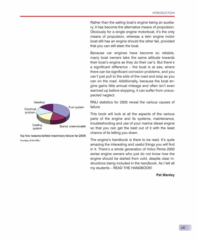
Because car engines have become so reliable, many boat owners take the same attitude towards their boat’s engine as they do their car’s. But there’s a signifi cant difference — the boat is at sea, where there can be signifi cant corrosion problems, and you can’t just pull to the side of the road and stop as you can on the road. Additionally, because the boat en-gine gains little annual mileage and often isn’t even warmed up before stopping, it can suffer from unsus-pected neglect.
RNLI statistics for 2005 reveal the various causes of failure.
This book will look at all the aspects of the various parts of the engine and its systems, maintenance, troubleshooting and use of your marine diesel engine so that you can get the best out of it with the least chance of its letting you down.
The engine’s handbook is there to be read. It’s quite amazing the interesting and useful things you will fi nd in it. There’s a whole generation of Volvo Penta 2000 series engine owners who just do not know how the engine should be started from cold, despite clear in-structions being included in the handbook. As I tell all my students — READ THE HANDBOOK!
Pat Manley

1
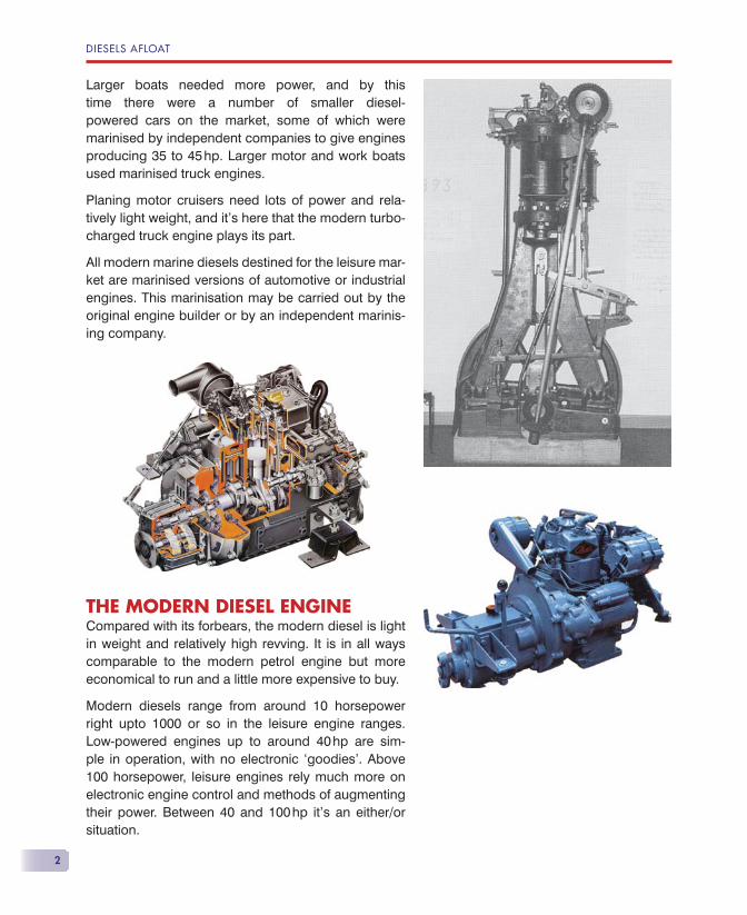
HOW IT ALL STARTEDRudolf Diesel was granted the fi rst patent for a diesel engine in 1892, when petrol engines were in their infancy. Whereas petrol engines could be built small enough to be put in a motor car, the diesel engine was on a different scale completely. Early examples were 3 metres tall!
Although diesels were used in German fl ying boats and even Zeppelins in the 1930s, they were really too big and heavy and were not considered a success.
It was not until the late 1950s that any real success was achieved in building small, relatively lightweight diesels for use in small leisure craft. These were one-, two- and three-cylinder engines revving at around 2300 rpm and developing from 7 to 35 hp. They were quite heavy and bulky, but the smallest could be fitted into a 20-foot boat.
In 1970 Petter produced a 6 hp single-cylinder engine built mainly from aluminium and derived from one of their small industrial units. This was very compact, light in weight and revved at 1500 rpm. This was quickly fol-lowed by a two-cylinder 12 hp version.
The Diesel Engine
DIESELS AFLOAT
2
Larger boats needed more power, and by this time there were a number of smaller diesel-powered cars on the market, some of which were marinised by independent companies to give engines producing 35 to 45 hp. Larger motor and work boats used marinised truck engines.
Planing motor cruisers need lots of power and rela-tively light weight, and it’s here that the modern turbo-charged truck engine plays its part.
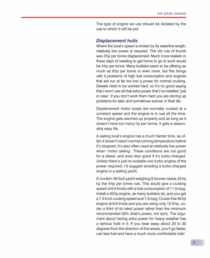
All modern marine diesels destined for the leisure mar-ket are marinised versions of automotive or industrial engines. This marinisation may be carried out by the original engine builder or by an independent marinis-ing company.
THE MODERN DIESEL ENGINECompared with its forbears, the modern diesel is light in weight and relatively high revving. It is in all ways comparable to the modern petrol engine but more economical to run and a little more expensive to buy.
Modern diesels range from around 10 horsepower right upto 1000 or so in the leisure engine ranges. Low-powered engines up to around 40 hp are sim-ple in operation, with no electronic ‘goodies’. Above 100 horsepower, leisure engines rely much more on electronic engine control and methods of augmenting their power. Between 40 and 100 hp it’s an either/or situation.
THE DIESEL ENGINE
3
The type of engine we use should be dictated by the use to which it will be put.
Displacement hullsWhere the boat’s speed is limited by its waterline length, relatively low power is required. The old rule of thumb was 2 hp per tonne displacement. Much more realistic in these days of needing to get home to go to work would be 4 hp per tonne. Many builders seem to be offering as much as 6 hp per tonne or even more, but this brings with it problems of high fuel consumption and engines that are run at far too low a power for normal cruising. Diesels need to be worked hard, so it’s no good saying that I won’t use all that extra power that I’ve installed ‘just in case’. If you don’t work them hard you are storing up problems for later, and sometimes sooner, in their life.
Displacement motor boats are normally cruised at a constant speed and the engine is in use all the time. The engine gets warmed up properly and as long as it doesn’t have too many hp per tonne, it gets a reason-ably easy life.
A sailing boat’s engine has a much harder time, as of-ten it doesn’t reach normal running temperature before it’s stopped. It’s also often used at relatively low power when ‘motor sailing’. These conditions are not good for a diesel, and even less good if it’s turbo-charged. Unless there’s just no suitable non-turbo engine of the power required, I’d suggest avoiding a turbo-charged engine in a sailing yacht.
A modern 36-foot yacht weighing 6 tonnes needs 24 hp by the 4 hp per tonne rule. This would give a cruising speed of 6.6 knots with a fuel consumption of 11.5 mpg. Install a 40 hp engine, as many builders do, and you get a 7.3 knot cruising speed and 7.3 mpg. Cruise that 40 hp engine at 6.6 knots and you are using only 12.5 hp, un-der a third of its rated power rather than the minimum recommended 50% (that’s power, not rpm). The argu-ment about having extra power for heavy weather has a serious hole in it. If you bear away about 20 to 30 degrees from the direction of the waves, you’ll go faster, use less fuel and have a much more comfortable ride!
DIESELS AFLOAT
4
Semi-displacement and planing hullsThese hulls need much more power than a displace-ment hull. Because of the demands that the engine should be as light and as compact as possible, these engines are normally turbo-charged and have electronic engine management. To save carrying redundant weight, these engines are normally cruised at about 300 rpm below maximum continuous rpm. Heavy weather will require a reduction of speed, so you don’t need any extra power.
Hull design and desired cruising speed affects the power requirement and it’s not easy to use any rule of thumb, as it is for a displacement hull. Once the hull gets beyond ‘displacement speed’ you’ll almost certainly be using enough power to avoid problems caused by running a diesel at too low a power. If you are forced to slow to displacement speed and you’ve got two engines, shut one down if safe to do so.
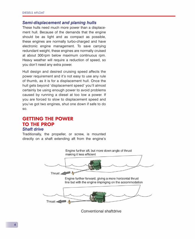
GETTING THE POWER TO THE PROPShaft driveTraditionally, the propeller, or screw, is mounted directly on a shaft extending aft from the engine’s
THE DIESEL ENGINE
5
‘gearbox’ and exiting through a waterproof gland towards the rear of the hull. Traditional hulls were relatively deep and the shaft could exit more or less horizontally. Modern hulls are relatively shallow, so if the downwards angle of the shaft is not to be too great, the engine needs to be mounted fairly well for-ward in the hull, but this may then intrude on the ac-commodation space.
Advantages:
• simple design;
• relatively cheap to make;
• easy maintenance;
• thrust bearings can be used so that no thrust load goes into the gearbox or through the engine mounts.
Disadvantages:
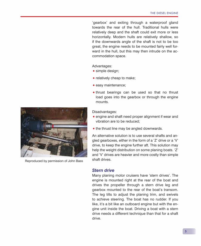
• engine and shaft need proper alignment if wear and vibration are to be reduced;
• the thrust line may be angled downwards.
An alternative solution is to use several shafts and an-gled gearboxes, either in the form of a ‘Z’ drive or a ‘V’ drive, to keep the engine further aft. This solution may help the weight distribution on some planing boats. ‘Z’ and ‘V’ drives are heavier and more costly than simple shaft drives.
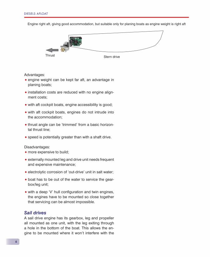
Stern driveMany planing motor cruisers have ‘stern drives’. The engine is mounted right at the rear of the boat and drives the propeller through a stern drive leg and gearbox mounted to the rear of the boat’s transom. The leg tilts to adjust the planing trim, and swivels to achieve steering. The boat has no rudder. If you like, it’s a bit like an outboard engine but with the en-gine unit inside the boat. Driving a boat with a stern drive needs a different technique than that for a shaft drive.
Reproduced by permission of John Bass
DIESELS AFLOAT
6
Advantages:
• engine weight can be kept far aft, an advantage in planing boats;
• installation costs are reduced with no engine align-ment costs;
• with aft cockpit boats, engine accessibility is good;
• with aft cockpit boats, engines do not intrude into the accommodation;
• thrust angle can be ‘trimmed’ from a basic horizon-tal thrust line;
• speed is potentially greater than with a shaft drive.
Disadvantages:
• more expensive to build;
• externally mounted leg and drive unit needs frequent and expensive maintenance;
• electrolytic corrosion of ‘out-drive’ unit in salt water;
• boat has to be out of the water to service the gear-box/leg unit;
• with a deep ‘V’ hull confi guration and twin engines, the engines have to be mounted so close together that servicing can be almost impossible.
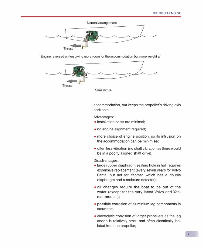
Sail drivesA sail drive engine has its gearbox, leg and propeller all mounted as one unit, with the leg exiting through a hole in the bottom of the boat. This allows the en-gine to be mounted where it won’t interfere with the
Engine right aft, giving good accommodation, but suitable only for planing boats as engine weight is right aft
Stern driveThrust
THE DIESEL ENGINE
7
accommodation, but keeps the propeller’s driving axis horizontal.
Advantages:
• installation costs are minimal;
• no engine alignment required;
• more choice of engine position, so its intrusion on the accommodation can be minimised;
• often less vibration (no shaft vibration as there would be in a poorly aligned shaft drive).
Disadvantages:
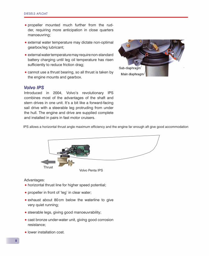
• large rubber diaphragm sealing hole in hull requires expensive replacement (every seven years for Volvo Penta, but not for Yanmar, which has a double diaphragm and a moisture detector);
• oil changes require the boat to be out of the water (except for the very latest Volvo and Yan-mar models);
• possible corrosion of aluminium leg components in seawater;
• electrolytic corrosion of larger propellers as the leg anode is relatively small and often electrically iso-lated from the propeller;
DIESELS AFLOAT
8
• propeller mounted much further from the rud-der, requiring more anticipation in close quarters manoeuvring;
• external water temperature may dictate non-optimal gearbox/leg lubricant;
• external water temperature may require non-standard battery charging until leg oil temperature has risen suffi ciently to reduce friction drag;
• cannot use a thrust bearing, so all thrust is taken by the engine mounts and gearbox.
Volvo IPSIntroduced in 2004, Volvo’s revolutionary IPS combines most of the advantages of the shaft and stern drives in one unit. It’s a bit like a forward-facing sail drive with a steerable leg protruding from under the hull. The engine and drive are supplied complete and installed in pairs in fast motor cruisers.
Advantages:
• horizontal thrust line for higher speed potential;
• propeller in front of ‘leg’ in clear water;
• exhaust about 80 cm below the waterline to give very quiet running;
• steerable legs, giving good manoeuvrability;
• cast bronze under-water unit, giving good corrosion resistance;
• lower installation cost.
IPS allows a horizontal thrust angle maximum efficiency and the engine far enough aft give good accommodation
ThrustVolvo Penta IPS
THE DIESEL ENGINE
9
Disadvantages:
• high unit cost;
• available only with a couple of 4—500 hp Volvo Penta engines.
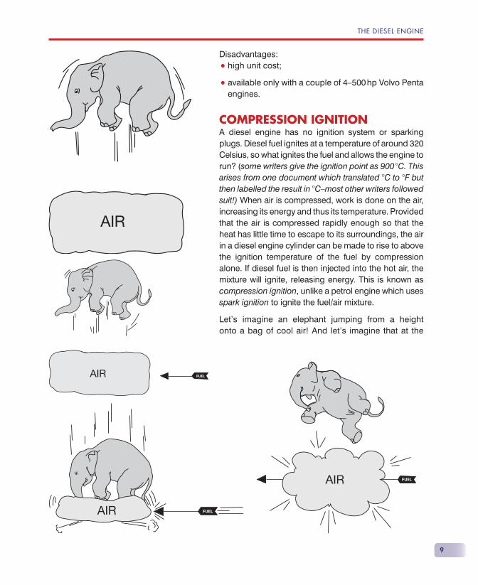
COMPRESSION IGNITIONA diesel engine has no ignition system or sparking plugs. Diesel fuel ignites at a temperature of around 320 Celsius, so what ignites the fuel and allows the engine to run? (some writers give the ignition point as 900 �C. This arises from one document which translated �C to �F but then labelled the result in �C—most other writers followed suit!) When air is compressed, work is done on the air, increasing its energy and thus its temperature. Provided that the air is compressed rapidly enough so that the heat has little time to escape to its surroundings, the air in a diesel engine cylinder can be made to rise to above the ignition temperature of the fuel by compression alone. If diesel fuel is then injected into the hot air, the mixture will ignite, releasing energy. This is known as compression ignition, unlike a petrol engine which uses spark ignition to ignite the fuel/air mixture.
Let’s imagine an elephant jumping from a height onto a bag of cool air! And let’s imagine that at the
DIESELS AFLOAT
10
same time, an archer shoots an arrow full of diesel fuel aimed to arrive at the bag of air at exactly the same time as the elephant. As the bag of air is very rapidly compressed by the arrival of the elephant, the arrow with exactly the correct amount of fuel arrives and penetrates the bag of now very hot air. There’s only one inevitable outcome: the elephant gets a free ride!
Very simplistic, I know, but the basic diesel engine is as simple as that. If the air is heated to above the com-bustion temperature of the fuel very rapidly AND if the correct amount of fuel is injected into this hot air at the correct time, the engine will run. No electricity is required, except to turn the engine over fast enough to start the engine.
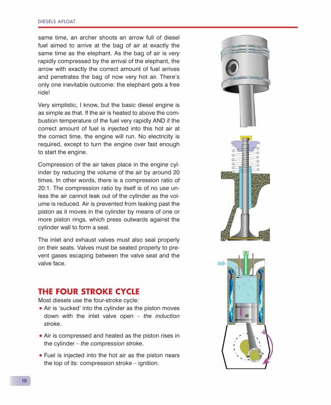
Compression of the air takes place in the engine cyl-inder by reducing the volume of the air by around 20 times. In other words, there is a compression ratio of 20:1. The compression ratio by itself is of no use un-less the air cannot leak out of the cylinder as the vol-ume is reduced. Air is prevented from leaking past the piston as it moves in the cylinder by means of one or more piston rings, which press outwards against the cylinder wall to form a seal.
The inlet and exhaust valves must also seal properly on their seats. Valves must be seated properly to pre-vent gases escaping between the valve seat and the valve face.
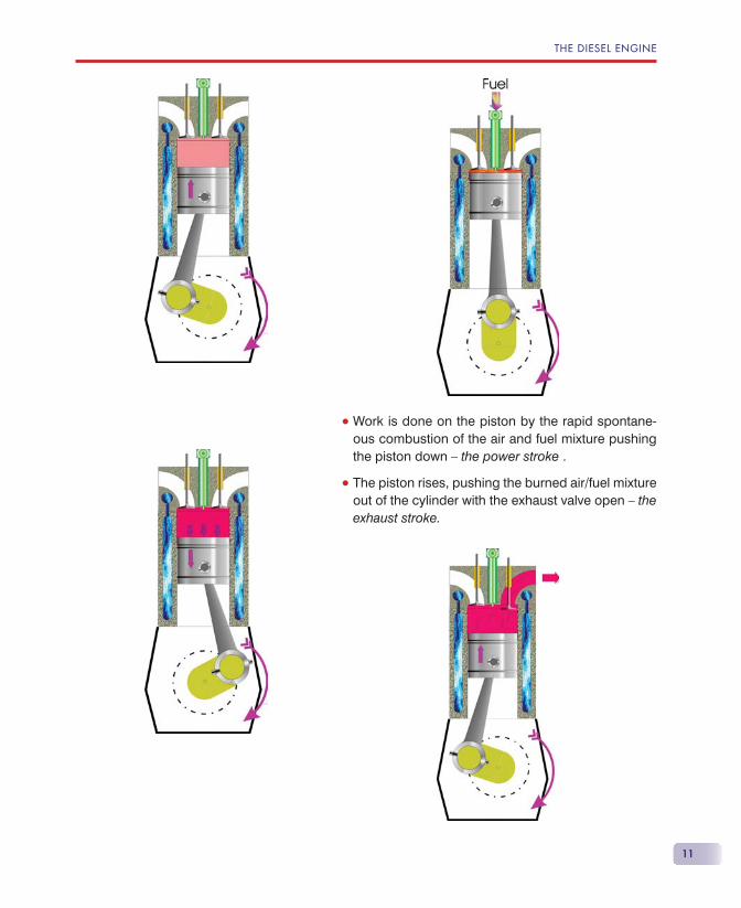
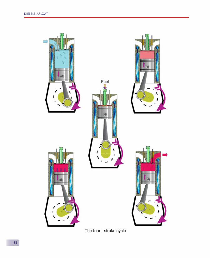
THE FOUR STROKE CYCLEMost diesels use the four-stroke cycle:
• Air is ‘sucked’ into the cylinder as the piston moves down with the inlet valve open — the induction stroke.
• Air is compressed and heated as the piston rises in the cylinder — the compression stroke.
• Fuel is injected into the hot air as the piston nears the top of its: compression stroke — ignition.
THE DIESEL ENGINE
11
• Work is done on the piston by the rapid spontane-ous combustion of the air and fuel mixture pushing the piston down — the power stroke .
• The piston rises, pushing the burned air/fuel mixture out of the cylinder with the exhaust valve open — the exhaust stroke.
DIESELS AFLOAT
12
THE DIESEL ENGINE
13
Note that the piston moves up and down twice for each ‘bang’ or power stroke. The valves operate only once for each two revolutions of the engine crankshaft. You get only one bang for each two revolutions in a single-cylinder, four-stroke engine.
The essential requirements for a diesel engine to start are:
• Adequate compression, supplied by the cylin-der bore, piston rings and valve seats all being in excellent condition so that the temperature of the air is raised to the ignition temperature of the fuel.
• Rotating the engine quickly enough to obtain rapid compression to minimise the escape of heat from the cylinder — this requires a well-charged battery of suffi cient power if electric starting is used.
• The correct quantity of fuel injected at the correct time.
It can be seen that a diesel engine in good mechanical condition will start if it is turned over rapidly enough to raise the air temperature to ignition point and the correct quantity of fuel is injected at the right time. It should be noted that other than powering the starter motor, the basic diesel engine requires no electricity for its operation.
MULTI-CYLINDER ENGINESFour-stroke multi-cylinder engines have the crank-shaft and valve timing arranged so that the ‘bangs’ don’t all occur at the same time. The ‘fi ring order’ for the cylinders is designed to give the smoothest running. Some engines use gear-driven counterbal-ance weights in the crankcase to give even smoother running.
TURBO-CHARGINGThere is a point at which adding more fuel to the air in the cylinder of a diesel engine will produce no extra power. The extra fuel will be wasted because there is insuffi cient air to burn it.

DIESELS AFLOAT
14
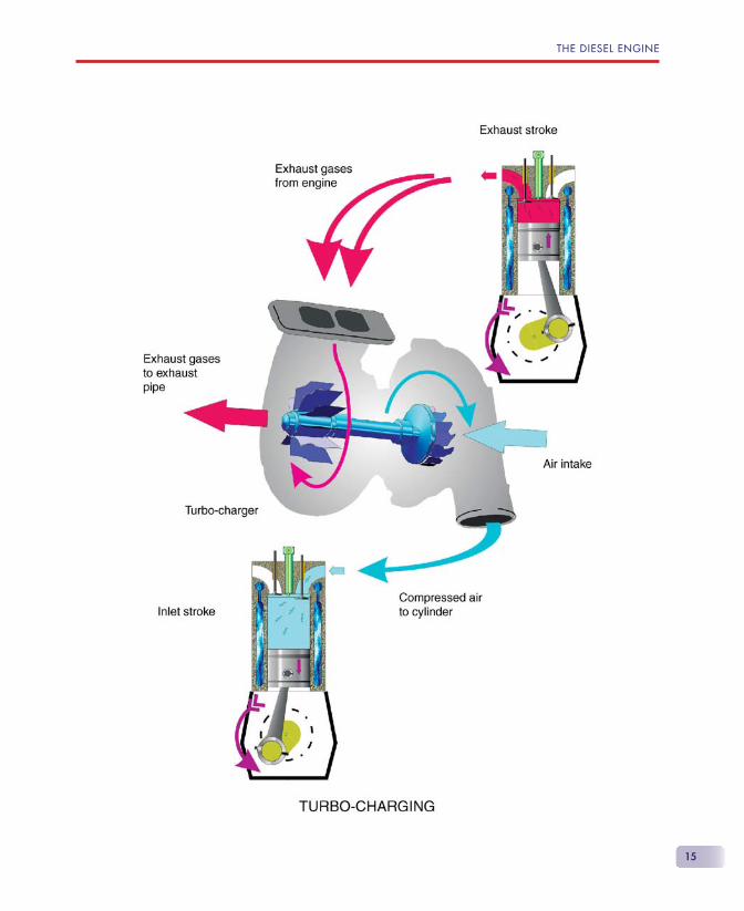
There are several ways to provide more air: make the engine physically bigger by having bigger cylin-ders or more cylinders of the same size, or feed the engine with heavier air. Making the engine bigger increases its weight as well as its size, and where we need lots of power from an engine, such as in a planing motor cruiser, this method will be imprac-ticable. We need more power per kilogram of en-gine and more power per ‘litre’ of engine than this method can provide. However, we can ‘feed’ the engine with compressed air, and then add more fuel to this heavier air to produce more power. The nor-mal method of achieving this is by adding a turbo-charger to the engine.
There is still plenty of energy remaining in the ex-haust gases that are ejected from the engine’s cyl-inder after combustion. Putting a ‘fan’ in the exhaust gases can harness this energy. The fan drives a compressor, which then supplies the cylinder with ‘heavy air’ rather than air at atmospheric pressure. If you double the mass of air you supply, you can add twice the mass of fuel and theoretically produce twice the horsepower than you would get from a ‘naturally aspirated’ engine. Producing more power increases the load on the engine’s components. Double the fuel and you double the ‘bang’ hitting the top of the piston. In order to retain reasonable reliability, the increase in power provided by turbo-charging is usually limited to an increase of 50% of the normally aspirated engine. The diagram shows how its done.
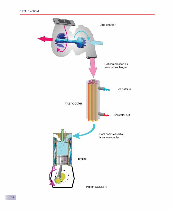
Compressing the air, as we know, raises its tempera-ture. Raising its temperature lowers its density. Thus, the increase in mass of the compressed air will not be as much as we thought, due to this increase in temperature. We will, therefore, need a bigger turbo-charger to make up for this shortfall, and this will cost more money.
We could cool the air after it’s been compressed to increase its density and allow us to use a smaller tur-bo-charger. This would give us a smaller and cheaper
THE DIESEL ENGINE
15
DIESELS AFLOAT
16
THE DIESEL ENGINE
17
turbo-charger, but we would now have to buy a cooler. The balance in cost occurs around 80 to 130 hp, so that smaller engines have no cooler and bigger ones do. It’s all a matter of economics.
The cooler is fi tted between the turbo-charger outlet and the engine air intake, and is usually called an inter-cooler. However, this same inter-cooler also goes by the name of pre-cooler or after-cooler.
Road vehicles use air to cool the engine and turbo-charger heat exchangers. Marine engines use ‘raw’ water to cool the heat exchangers because there is insuffi cient air fl ow to give effective cooling in most cases. Raw water is the water the boat is fl oating in, normally seawater.
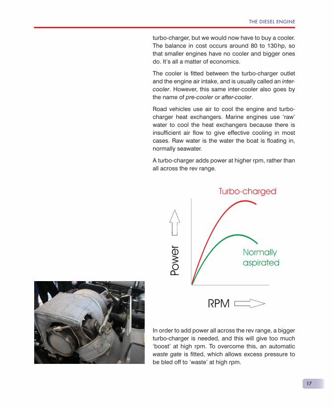
A turbo-charger adds power at higher rpm, rather than all across the rev range.
In order to add power all across the rev range, a bigger turbo-charger is needed, and this will give too much ‘boost’ at high rpm. To overcome this, an automatic waste gate is fi tted, which allows excess pressure to be bled off to ‘waste’ at high rpm.
DIESELS AFLOAT
18
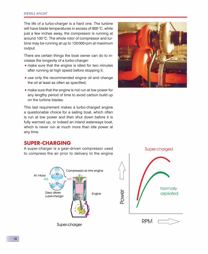
The life of a turbo-charger is a hard one. The turbine will have blade temperatures in excess of 900 �C, while just a few inches away, the compressor is running at around 100 �C. The whole rotor of compressor and tur-bine may be running at up to 120 000 rpm at maximum output.
There are certain things the boat owner can do to in-crease the longevity of a turbo-charger:
• make sure that the engine is idled for two minutes after running at high speed before stopping it;
• use only the recommended engine oil and change the oil at least as often as specifi ed;
• make sure that the engine is not run at low power for any lengthy period of time to avoid carbon build up on the turbine blades.
This last requirement makes a turbo-charged engine a questionable choice for a sailing boat, which often is run at low power and then shut down before it is fully warmed up, or indeed an inland waterways boat, which is never run at much more than idle power at any time.
SUPER-CHARGINGA super-charger is a gear-driven compressor used to compress the air prior to delivery to the engine
THE DIESEL ENGINE
19
to increase the power of the basic engine in the same way as a turbo-charger. It can be geared to produce extra power at low rpm. It is not usually used on marine diesels. Volvo Penta does, how-ever, use a combination of both super-charger and turbo-charger to increase the power over the whole rev range. This produces a relatively com-pact, high-power engine, at the expense of extra complexity.
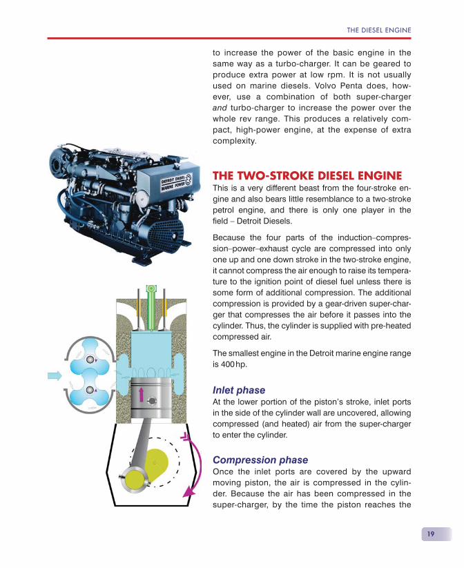
THE TWO-STROKE DIESEL ENGINEThis is a very different beast from the four-stroke en-gine and also bears little resemblance to a two-stroke petrol engine, and there is only one player in the fi eld — Detroit Diesels.
Because the four parts of the induction—compres-sion—power—exhaust cycle are compressed into only one up and one down stroke in the two-stroke engine, it cannot compress the air enough to raise its tempera-ture to the ignition point of diesel fuel unless there is some form of additional compression. The additional compression is provided by a gear-driven super-char-ger that compresses the air before it passes into the cylinder. Thus, the cylinder is supplied with pre-heated compressed air.
The smallest engine in the Detroit marine engine range is 400 hp.
Inlet phaseAt the lower portion of the piston’s stroke, inlet ports in the side of the cylinder wall are uncovered, allowing compressed (and heated) air from the super-charger to enter the cylinder.
Compression phaseOnce the inlet ports are covered by the upward moving piston, the air is compressed in the cylin-der. Because the air has been compressed in the super-charger, by the time the piston reaches the
DIESELS AFLOAT
20
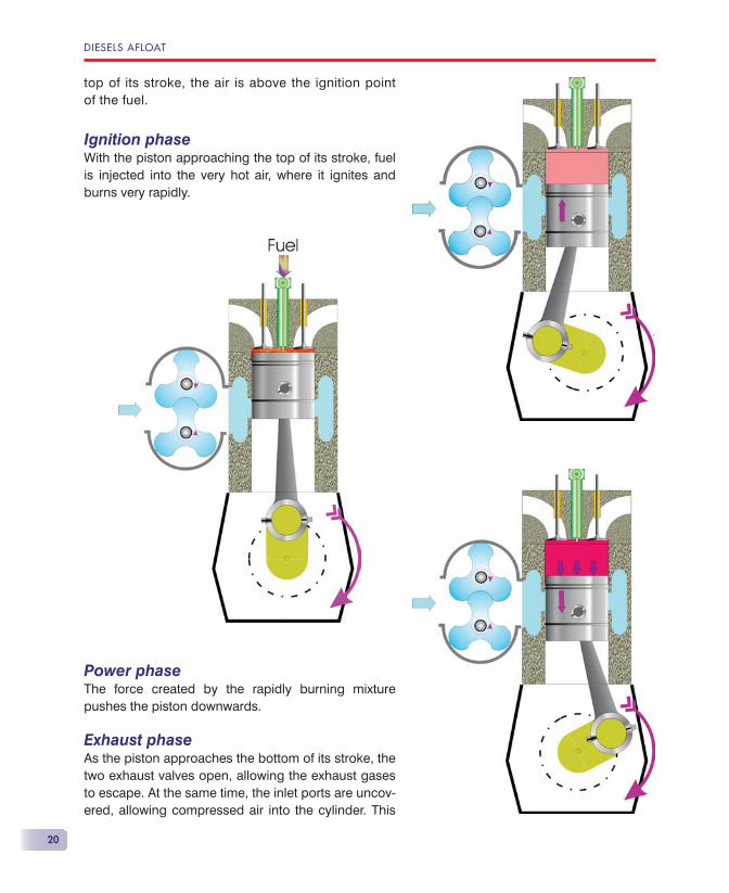
top of its stroke, the air is above the ignition point of the fuel.
Ignition phaseWith the piston approaching the top of its stroke, fuel is injected into the very hot air, where it ignites and burns very rapidly.
Power phaseThe force created by the rapidly burning mixture pushes the piston downwards.
Exhaust phaseAs the piston approaches the bottom of its stroke, the two exhaust valves open, allowing the exhaust gases to escape. At the same time, the inlet ports are uncov-ered, allowing compressed air into the cylinder. This
THE DIESEL ENGINE
21
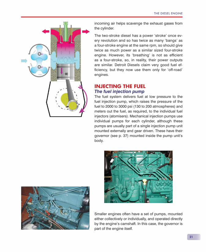
incoming air helps scavenge the exhaust gases from the cylinder.
The two-stroke diesel has a power ‘stroke’ once ev-ery revolution and so has twice as many ‘bangs’ as a four-stroke engine at the same rpm, so should give twice as much power as a similar sized four-stroke engine. However, its ‘breathing’ is not as effi cient as a four-stroke, so, in reality, their power outputs are similar. Detroit Diesels claim very good fuel ef-fi ciency, but they now use them only for ‘off-road’ engines.
INJECTING THE FUELThe fuel injection pumpThe fuel system delivers fuel at low pressure to the fuel injection pump, which raises the pressure of the fuel to 2000 to 3000 psi (130 to 200 atmospheres) and meters out the fuel, as required, to the individual fuel injectors (atomisers). Mechanical injection pumps use individual pumps for each cylinder, although these pumps are usually part of a single injection pump unit mounted externally and gear driven. These have their governor (see p. 37) mounted inside the pump unit’s body.
Smaller engines often have a set of pumps, mounted either collectively or individually, and operated directly by the engine’s camshaft. In this case, the governor is part of the engine itself.
DIESELS AFLOAT
22
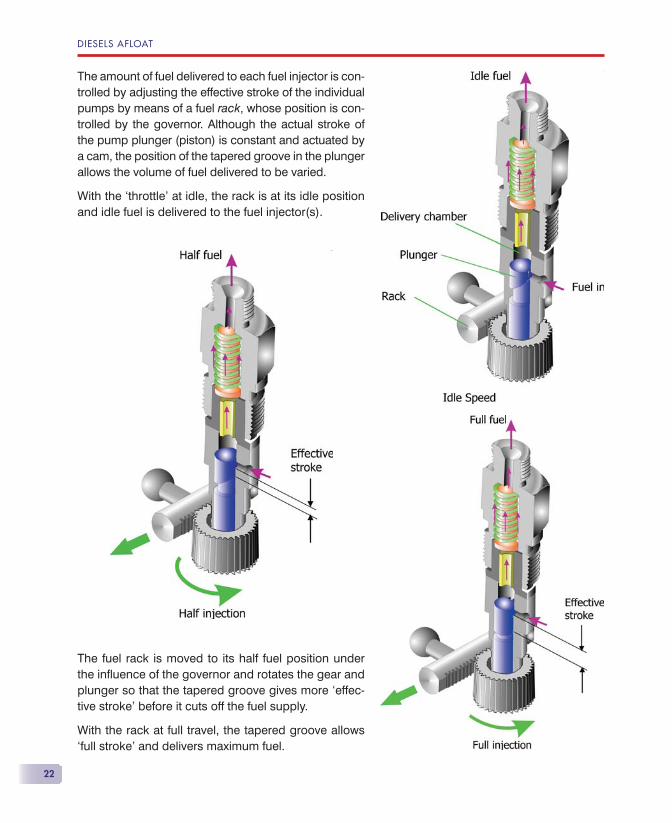
The amount of fuel delivered to each fuel injector is con-trolled by adjusting the effective stroke of the individual pumps by means of a fuel rack, whose position is con-trolled by the governor. Although the actual stroke of the pump plunger (piston) is constant and actuated by a cam, the position of the tapered groove in the plunger allows the volume of fuel delivered to be varied.
With the ‘throttle’ at idle, the rack is at its idle position and idle fuel is delivered to the fuel injector(s).
The fuel rack is moved to its half fuel position under the infl uence of the governor and rotates the gear and plunger so that the tapered groove gives more ‘effec-tive stroke’ before it cuts off the fuel supply.
With the rack at full travel, the tapered groove allows ‘full stroke’ and delivers maximum fuel.
THE DIESEL ENGINE
23
Some engines use a slightly different type of injection pump and have a hydraulic governor. Essentially, all fuel injection pumps are precision-made and cannot be serviced by the user.
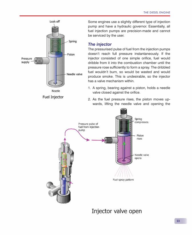
The injectorThe pressurised pulse of fuel from the injection pumps doesn’t reach full pressure instantaneously. If the injector consisted of one simple orifi ce, fuel would dribble from it into the combustion chamber until the pressure rose suffi ciently to form a spray. The dribbled fuel wouldn’t burn, so would be wasted and would produce smoke. This is undesirable, so the injector has a valve mechanism within.
A spring, bearing against a piston, holds a needle valve closed against the orifi ce.
As the fuel pressure rises, the piston moves up-wards, lifting the needle valve and opening the
1.
2.
DIESELS AFLOAT
24
orifi ce, allowing a controlled spray pattern to emerge.
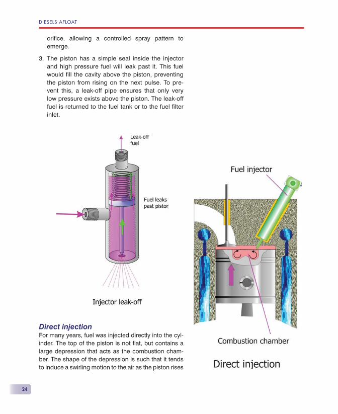
The piston has a simple seal inside the injector and high pressure fuel will leak past it. This fuel would fi ll the cavity above the piston, preventing the piston from rising on the next pulse. To pre-vent this, a leak-off pipe ensures that only very low pressure exists above the piston. The leak-off fuel is returned to the fuel tank or to the fuel fi lter inlet.
Direct injectionFor many years, fuel was injected directly into the cyl-inder. The top of the piston is not fl at, but contains a large depression that acts as the combustion cham-ber. The shape of the depression is such that it tends to induce a swirling motion to the air as the piston rises
3.
THE DIESEL ENGINE
25
on the compression stroke. The injector directs the fuel spray, at an angle, towards the depression, so that the fuel is mixed with the swirling air in as homogenous a way as possible.
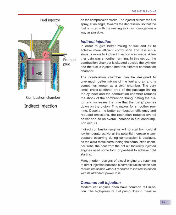
Indirect injectionIn order to give better mixing of fuel and air to achieve more effi cient combustion and less emis-sions, a move to indirect injection was made. A fur-ther gain was smoother running. In this set-up, the combustion chamber is situated outside the cylinder and the fuel is injected into this external combustion chamber.
The combustion chamber can be designed to give much better mixing of the fuel and air and is sometimes known as a swirl chamber. The very small cross-sectional area of the passage linking the cylinder and the combustion chamber reduces the shock of the combustion ‘bang’ hitting the pis-ton and increases the time that the ‘bang’ pushes down on the piston. This makes for smoother run-ning. Despite the better combustion efficiency and reduced emissions, the restriction reduces overall power and so an overall increase in fuel consump-tion occurs.
Indirect combustion engines will not start from cold at low temperatures. Not all the potential increase in tem-perature occurring during compression is available, as the extra metal surrounding the combustion cham-ber ‘robs’ the heat from the hot air. Indirectly injected engines need some form of pre-heat to achieve cold starting.
Many modern designs of diesel engine are returning to direct injection because electronic fuel injection can reduce emissions without recourse to indirect injection with its attendant power loss.
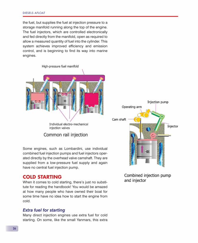
Common rail injectionModern car engines often have common rail injec-tion. The high-pressure fuel pump doesn’t measure
DIESELS AFLOAT
26
the fuel, but supplies the fuel at injection pressure to a storage manifold running along the top of the engine. The fuel injectors, which are controlled electronically and fed directly from the manifold, open as required to allow a measured quantity of fuel into the cylinder. This system achieves improved effi ciency and emission control, and is beginning to fi nd its way into marine engines.
Some engines, such as Lombardini, use individual combined fuel injection pumps and fuel injectors oper-ated directly by the overhead valve camshaft. They are supplied from a low-pressure fuel supply and again have no central fuel injection pump.
COLD STARTINGWhen it comes to cold starting, there’s just no substi-tute for reading the handbook! You would be amazed at how many people who have owned their boat for some time have no idea how to start the engine from cold.
Extra fuel for startingMany direct injection engines use extra fuel for cold starting. On some, like the small Yanmars, this extra
THE DIESEL ENGINE
27
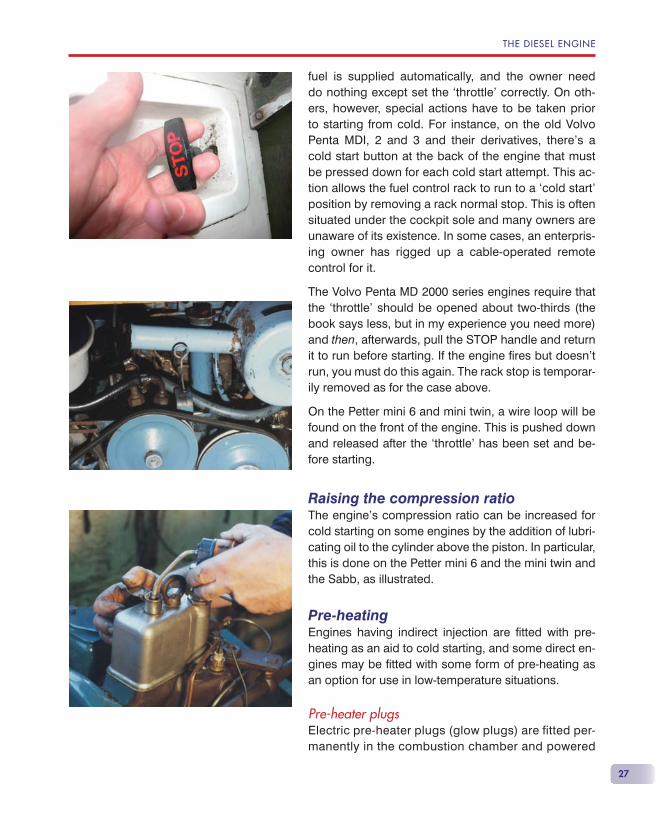
fuel is supplied automatically, and the owner need do nothing except set the ‘throttle’ correctly. On oth-ers, however, special actions have to be taken prior to starting from cold. For instance, on the old Volvo Penta MDI, 2 and 3 and their derivatives, there’s a cold start button at the back of the engine that must be pressed down for each cold start attempt. This ac-tion allows the fuel control rack to run to a ‘cold start’ position by removing a rack normal stop. This is often situated under the cockpit sole and many owners are unaware of its existence. In some cases, an enterpris-ing owner has rigged up a cable-operated remote control for it.
The Volvo Penta MD 2000 series engines require that the ‘throttle’ should be opened about two-thirds (the book says less, but in my experience you need more) and then, afterwards, pull the STOP handle and return it to run before starting. If the engine fi res but doesn’t run, you must do this again. The rack stop is temporar-ily removed as for the case above.
On the Petter mini 6 and mini twin, a wire loop will be found on the front of the engine. This is pushed down and released after the ‘throttle’ has been set and be-fore starting.
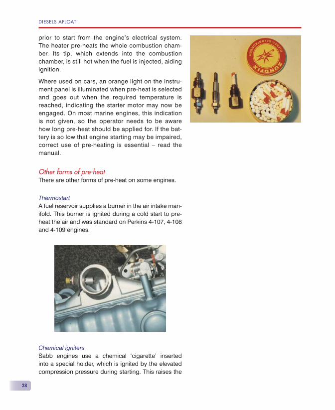
Raising the compression ratioThe engine’s compression ratio can be increased for cold starting on some engines by the addition of lubri-cating oil to the cylinder above the piston. In particular, this is done on the Petter mini 6 and the mini twin and the Sabb, as illustrated.
Pre-heatingEngines having indirect injection are fi tted with pre-heating as an aid to cold starting, and some direct en-gines may be fi tted with some form of pre-heating as an option for use in low-temperature situations.
Pre-heater plugsElectric pre-heater plugs (glow plugs) are fitted per-manently in the combustion chamber and powered
DIESELS AFLOAT
28
prior to start from the engine’s electrical system. The heater pre-heats the whole combustion cham-ber. Its tip, which extends into the combustion chamber, is still hot when the fuel is injected, aiding ignition.
Where used on cars, an orange light on the instru-ment panel is illuminated when pre-heat is selected and goes out when the required temperature is reached, indicating the starter motor may now be engaged. On most marine engines, this indication is not given, so the operator needs to be aware how long pre-heat should be applied for. If the bat-tery is so low that engine starting may be impaired, correct use of pre-heating is essential — read the manual.
Other forms of pre-heatThere are other forms of pre-heat on some engines.
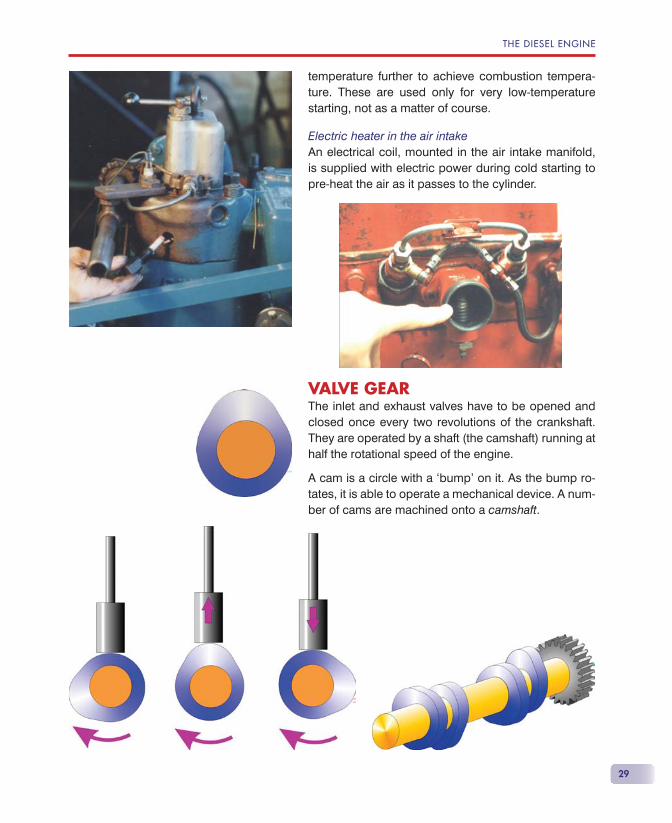
ThermostartA fuel reservoir supplies a burner in the air intake man-ifold. This burner is ignited during a cold start to pre-heat the air and was standard on Perkins 4-107, 4-108 and 4-109 engines.
Chemical ignitersSabb engines use a chemical ‘cigarette’ inserted into a special holder, which is ignited by the elevated compression pressure during starting. This raises the
THE DIESEL ENGINE
29
temperature further to achieve combustion tempera-ture. These are used only for very low-temperature starting, not as a matter of course.
Electric heater in the air intakeAn electrical coil, mounted in the air intake manifold, is supplied with electric power during cold starting to pre-heat the air as it passes to the cylinder.
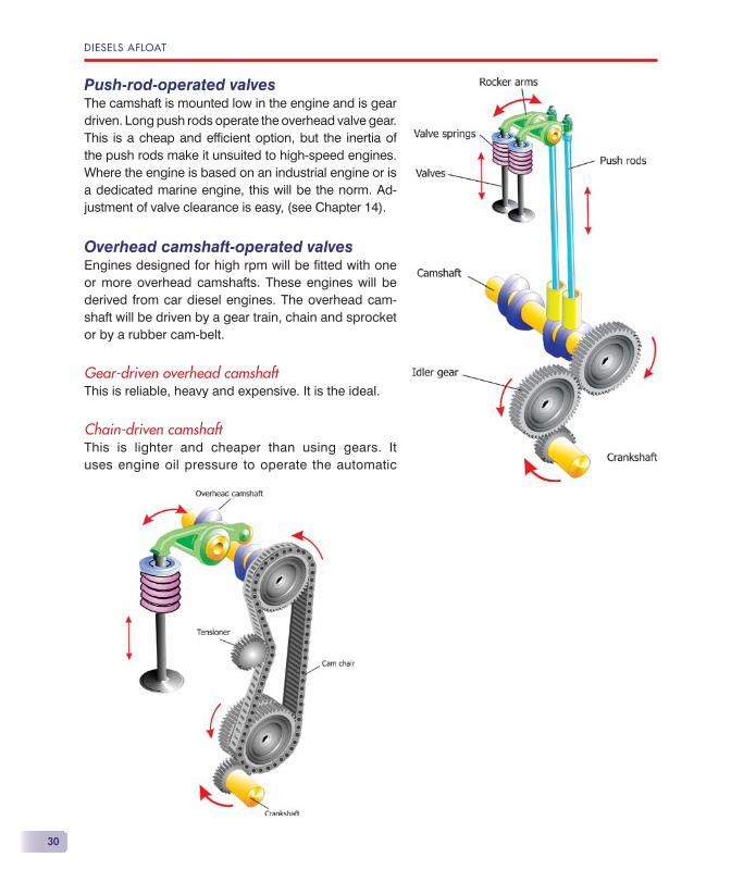
VALVE GEARThe inlet and exhaust valves have to be opened and closed once every two revolutions of the crankshaft. They are operated by a shaft (the camshaft) running at half the rotational speed of the engine.
A cam is a circle with a ‘bump’ on it. As the bump ro-tates, it is able to operate a mechanical device. A num-ber of cams are machined onto a camshaft.
DIESELS AFLOAT
30
Push-rod-operated valvesThe camshaft is mounted low in the engine and is gear driven. Long push rods operate the overhead valve gear. This is a cheap and effi cient option, but the inertia of the push rods make it unsuited to high-speed engines. Where the engine is based on an industrial engine or is a dedicated marine engine, this will be the norm. Ad-justment of valve clearance is easy, (see Chapter 14).
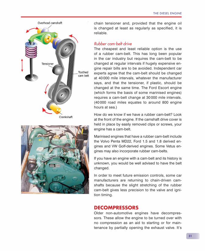
Overhead camshaft-operated valvesEngines designed for high rpm will be fi tted with one or more overhead camshafts. These engines will be derived from car diesel engines. The overhead cam-shaft will be driven by a gear train, chain and sprocket or by a rubber cam-belt.
Gear-driven overhead camshaftThis is reliable, heavy and expensive. It is the ideal.
Chain-driven camshaftThis is lighter and cheaper than using gears. It uses engine oil pressure to operate the automatic
THE DIESEL ENGINE
31
chain tensioner and, provided that the engine oil is changed at least as regularly as specified, it is reliable.
Rubber cam-belt driveThe cheapest and least reliable option is the use of a rubber cam-belt. This has long been popular in the car industry but requires the cam-belt to be changed at regular intervals if hugely expensive en-gine repair bills are to be avoided. Independent car experts agree that the cam-belt should be changed at 40 000 mile intervals, whatever the manufacturer says, and that the tensioner, if plastic, should be changed at the same time. The Ford Escort engine (which forms the basis of some marinised engines) requires a cam-belt change at 30 000 mile intervals. (40 000 road miles equates to around 800 engine hours at sea.)
How do we know if we have a rubber cam-belt? Look at the front of the engine. If the camshaft drive cover is held in place by easily removed clips or screws, your engine has a cam-belt.
Marinised engines that have a rubber cam-belt include the Volvo Penta MD22, Ford 1.5 and 1.8 derived en-gines and VW Golf-derived engines. Some Vetus en-gines may also incorporate rubber cam-belts.
If you have an engine with a cam-belt and its history is unknown, you would be well advised to have the belt changed.
In order to meet future emission controls, some car manufacturers are returning to chain-driven cam-shafts because the slight stretching of the rubber cam-belt gives less precision to the valve and igni-tion timing.
DECOMPRESSORSOlder non-automotive engines have decompres-sors. These allow the engine to be turned over with no compression as an aid to starting or for main-tenance by partially opening the exhaust valve. It’s
DIESELS AFLOAT
32
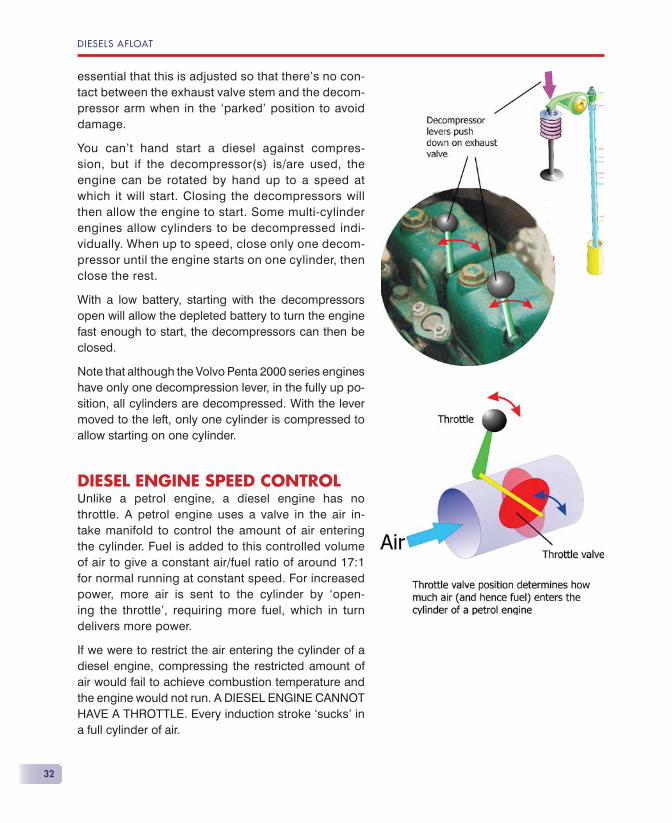
essential that this is adjusted so that there’s no con-tact between the exhaust valve stem and the decom-pressor arm when in the ‘parked’ position to avoid damage.
You can’t hand start a diesel against compres-sion, but if the decompressor(s) is/are used, the engine can be rotated by hand up to a speed at which it will start. Closing the decompressors will then allow the engine to start. Some multi-cylinder engines allow cylinders to be decompressed indi-vidually. When up to speed, close only one decom-pressor until the engine starts on one cylinder, then close the rest.
With a low battery, starting with the decompressors open will allow the depleted battery to turn the engine fast enough to start, the decompressors can then be closed.
Note that although the Volvo Penta 2000 series engines have only one decompression lever, in the fully up po-sition, all cylinders are decompressed. With the lever moved to the left, only one cylinder is compressed to allow starting on one cylinder.
DIESEL ENGINE SPEED CONTROLUnlike a petrol engine, a diesel engine has no throttle. A petrol engine uses a valve in the air in-take manifold to control the amount of air entering the cylinder. Fuel is added to this controlled volume of air to give a constant air/fuel ratio of around 17:1 for normal running at constant speed. For increased power, more air is sent to the cylinder by ‘open-ing the throttle’, requiring more fuel, which in turn delivers more power.
If we were to restrict the air entering the cylinder of a diesel engine, compressing the restricted amount of air would fail to achieve combustion temperature and the engine would not run. A DIESEL ENGINE CANNOT HAVE A THROTTLE. Every induction stroke ‘sucks’ in a full cylinder of air.
THE DIESEL ENGINE
33
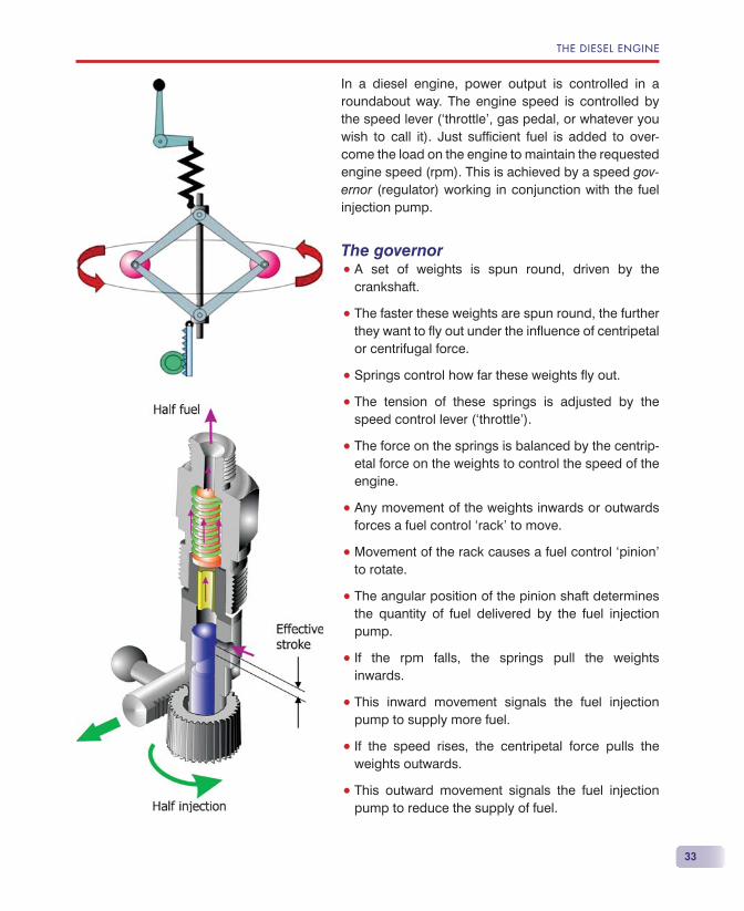
In a diesel engine, power output is controlled in a roundabout way. The engine speed is controlled by the speed lever (‘throttle’, gas pedal, or whatever you wish to call it). Just suffi cient fuel is added to over-come the load on the engine to maintain the requested engine speed (rpm). This is achieved by a speed gov-ernor (regulator) working in conjunction with the fuel injection pump.
The governor• A set of weights is spun round, driven by the
crankshaft.
• The faster these weights are spun round, the further they want to fl y out under the infl uence of centripetal or centrifugal force.
• Springs control how far these weights fl y out.
• The tension of these springs is adjusted by the speed control lever (‘throttle’).
• The force on the springs is balanced by the centrip-etal force on the weights to control the speed of the engine.
• Any movement of the weights inwards or outwards forces a fuel control ‘rack’ to move.
• Movement of the rack causes a fuel control ‘pinion’ to rotate.
• The angular position of the pinion shaft determines the quantity of fuel delivered by the fuel injection pump.
• If the rpm falls, the springs pull the weights inwards.
• This inward movement signals the fuel injection pump to supply more fuel.
• If the speed rises, the centripetal force pulls the weights outwards.
• This outward movement signals the fuel injection pump to reduce the supply of fuel.
DIESELS AFLOAT
34
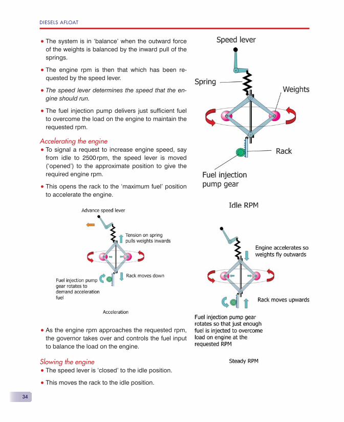
• The system is in ‘balance’ when the outward force of the weights is balanced by the inward pull of the springs.
• The engine rpm is then that which has been re-quested by the speed lever.
• The speed lever determines the speed that the en-gine should run.
• The fuel injection pump delivers just suffi cient fuel to overcome the load on the engine to maintain the requested rpm.
Accelerating the engine• To signal a request to increase engine speed, say
from idle to 2500 rpm, the speed lever is moved (‘opened’) to the approximate position to give the required engine rpm.
• This opens the rack to the ‘maximum fuel’ position to accelerate the engine.
• As the engine rpm approaches the requested rpm, the governor takes over and controls the fuel input to balance the load on the engine.
Slowing the engine• The speed lever is ‘closed’ to the idle position.
• This moves the rack to the idle position.
THE DIESEL ENGINE
35
• Pre-set idle fuel is supplied to the engine.
• The engine slows under the infl uence of the load to idle rpm.
Too much loadIf the load is so great that the requested rpm cannot be achieved, the governor will not control engine speed and acceleration fuel will continue to be supplied to the engine, even though the engine is running at a constant (too low) rpm.
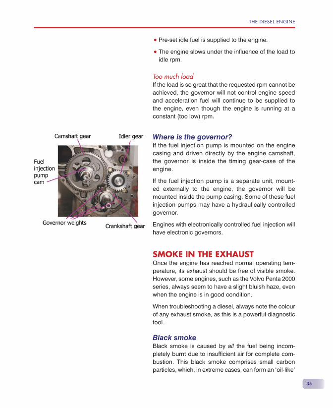
Where is the governor?If the fuel injection pump is mounted on the engine casing and driven directly by the engine camshaft, the governor is inside the timing gear-case of the engine.
If the fuel injection pump is a separate unit, mount-ed externally to the engine, the governor will be mounted inside the pump casing. Some of these fuel injection pumps may have a hydraulically controlled governor.
Engines with electronically controlled fuel injection will have electronic governors.
SMOKE IN THE EXHAUSTOnce the engine has reached normal operating tem-perature, its exhaust should be free of visible smoke. However, some engines, such as the Volvo Penta 2000 series, always seem to have a slight bluish haze, even when the engine is in good condition.
When troubleshooting a diesel, always note the colour of any exhaust smoke, as this is a powerful diagnostic tool.
Black smokeBlack smoke is caused by all the fuel being incom-pletely burnt due to insuffi cient air for complete com-bustion. This black smoke comprises small carbon particles, which, in extreme cases, can form an ‘oil-like’
DIESELS AFLOAT
36
layer on the surface of the water. Don’t be misled, this is carbon and not oil.
As we discussed earlier, a diesel engine sucks in a full cylinder of air on each induction stroke. Fuel is added to produce the required power to overcome the load to achieve the selected rpm. If too much fuel is added, such that there is insuffi cient air in the cylinder to burn it, black smoke will result. This black smoke represents fuel injected but not producing any power, and so is fuel wasted. This can happen under several circumstances.
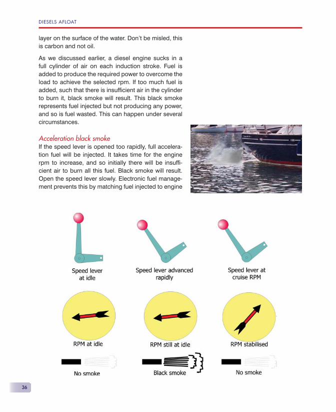
Acceleration black smokeIf the speed lever is opened too rapidly, full accelera-tion fuel will be injected. It takes time for the engine rpm to increase, and so initially there will be insuffi -cient air to burn all this fuel. Black smoke will result. Open the speed lever slowly. Electronic fuel manage-ment prevents this by matching fuel injected to engine
THE DIESEL ENGINE
37
acceleration, resulting in a clean exhaust, however fast the speed lever is opened.
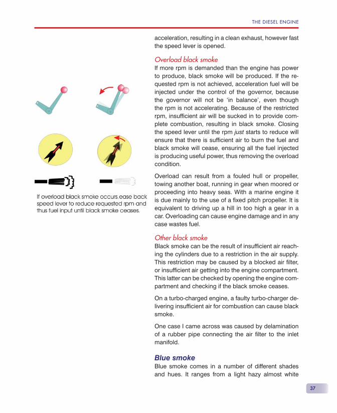
Overload black smokeIf more rpm is demanded than the engine has power to produce, black smoke will be produced. If the re-quested rpm is not achieved, acceleration fuel will be injected under the control of the governor, because the governor will not be ‘in balance’, even though the rpm is not accelerating. Because of the restricted rpm, insuffi cient air will be sucked in to provide com-plete combustion, resulting in black smoke. Closing the speed lever until the rpm just starts to reduce will ensure that there is suffi cient air to burn the fuel and black smoke will cease, ensuring all the fuel injected is producing useful power, thus removing the overload condition.
Overload can result from a fouled hull or propeller, towing another boat, running in gear when moored or proceeding into heavy seas. With a marine engine it is due mainly to the use of a fi xed pitch propeller. It is equivalent to driving up a hill in too high a gear in a car. Overloading can cause engine damage and in any case wastes fuel.
Other black smokeBlack smoke can be the result of insuffi cient air reach-ing the cylinders due to a restriction in the air supply. This restriction may be caused by a blocked air fi lter, or insuffi cient air getting into the engine compartment. This latter can be checked by opening the engine com-partment and checking if the black smoke ceases.
On a turbo-charged engine, a faulty turbo-charger de-livering insuffi cient air for combustion can cause black smoke.
One case I came across was caused by delamination of a rubber pipe connecting the air fi lter to the inlet manifold.
Blue smokeBlue smoke comes in a number of different shades and hues. It ranges from a light hazy almost white
DIESELS AFLOAT
38
colour through to dark blue. Watching a big diesel start shows a mixture of all possible hues!
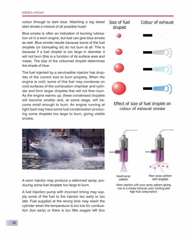
Blue smoke is often an indication of burning lubrica-tion oil in a worn engine, but fuel can give blue smoke as well. Blue smoke results because some of the fuel droplets (or lubricating oil) do not burn at all. This is because if a fuel droplet is too large in diameter it will not burn (this is a function of its surface area and mass). The size of the unburned droplet determines the shade of blue.
The fuel injected by a serviceable injector has drop-lets of the correct size to burn properly. When the engine is cold, some of this fuel may condense on cold surfaces of the combustion chamber and cylin-der and form larger droplets that will not then burn. As the engine warms up, these condensed droplets will become smaller and, at some stage, will be-come small enough to burn. An engine running at light load may have some fuel condensation produc-ing some droplets too large to burn, giving visible smoke.
A worn injector may produce a deformed spray, pro-ducing some fuel droplets too large to burn.
A fuel injection pump with incorrect timing may sup-ply some of the fuel to the injector too early or too late. Fuel supplied at the wrong time may reach the cylinder when the temperature is too low for combus-tion (too early) or there is too little oxygen left (too
THE DIESEL ENGINE
39
late). This fuel will be unburned and will result in blue smoke.
White smokeWhite smoke is water vapour. Lots of white smoke is lots of water vapour!
When a car is fi rst started on a cold, damp day you see white vapour coming from the exhaust. This is water vapour condensing in the exhaust, because for each gallon of petrol or diesel fuel burned, you get a gallon of water as a product of combustion.
On a boat with a water-cooled exhaust, the cooling water being injected into the exhaust system masks this relatively small amount of water vapour. Some people expect a cylinder-head gasket leak to show up as water vapour in the exhaust, but the quantity of water would be just too small to be seen on a boat.
Normally, a small engine would not have visible water vapour in the exhaust. A powerful engine being run at high speed, such as on a planing motor cruiser, would have a fair amount of water vapour visible in the ex-haust, and this is quite normal.
Some books describe the smoke from fuel injec-tion problems as being ‘white’. To me this is actu-ally ‘light grey’, but the difference is small. Watch a diesel, especially a big one, being started from cold and you will see quite a lot of varying colour smoke. The lightest of this is ‘light grey’. You would not ex-pect ‘white’ water vapour when starting from cold. Noting this should help to distinguish between the two.
CYLINDER BORE GLAZINGCertain operating conditions cause cylinder bore glazing, which reduces compression and increases oil consumption. Many yachtsmen deny the exis-tence of this phenomenon, so I went to three of the
DIESELS AFLOAT
40
world’s leading engine manufacturers, who all came up with very similar descriptions of what happens and why.
Basically, they all said: ‘don’t run a diesel engine under light load — ideally aim for a minimum of 60% load — and don’t run the engine too cool.’ They all made the comment that working a diesel engine lightly and letting it warm up too slowly was actually being cruel, rather than kind, to the engine.
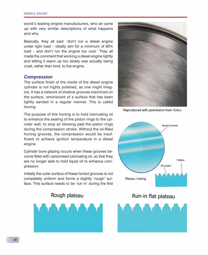
CompressionThe surface fi nish of the inside of the diesel engine cylinder is not highly polished, as one might imag-ine. It has a network of shallow grooves machined on the surface, reminiscent of a surface that has been lightly sanded in a regular manner. This is called honing.
The purpose of this honing is to hold lubricating oil to enhance the sealing of the piston rings to the cyl-inder wall, to stop air blowing past the piston rings during the compression stroke. Without the oil-fi lled honing grooves, the compression would be insuf-fi cient to achieve ignition temperature in a diesel engine.
Cylinder bore glazing occurs when these grooves be-come fi lled with carbonised lubricating oil, so that they are no longer able to hold liquid oil to enhance com-pression.
Initially the outer surface of these honed grooves is not completely uniform and forms a slightly ‘rough’ sur-face. This surface needs to be ‘run in’ during the fi rst
THE DIESEL ENGINE
41
few hours of the engine’s service to give a fl at plateau between the grooves.
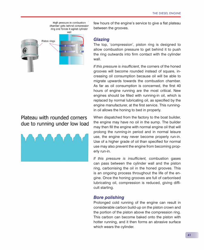
GlazingThe top, ‘compression’, piston ring is designed to allow combustion pressure to get behind it to push the ring outwards into fi rm contact with the cylinder wall.
If this pressure is insuffi cient, the corners of the honed grooves will become rounded instead of square, in-creasing oil consumption because oil will be able to migrate upwards towards the combustion chamber. As far as oil consumption is concerned, the fi rst 40 hours of engine running are the most critical. New engines should be fi lled with running-in oil, which is replaced by normal lubricating oil, as specifi ed by the engine manufacturer, at the fi rst service. This running-in oil allows the honing to bed in properly.
When dispatched from the factory to the boat builder, the engine may have no oil in the sump. The builder may then fi ll the engine with normal engine oil that will prolong the running-in period and in normal leisure use, the engine may never become properly run-in. Use of a higher grade of oil than specifi ed for normal use may also prevent the engine from becoming prop-erly run-in.
If this pressure is insuffi cient, combustion gases can pass between the cylinder wall and the piston ring, carbonising the oil in the honed grooves. This is an ongoing process throughout the life of the en-gine. Once the honing grooves are full of carbonised lubricating oil, compression is reduced, giving diffi -cult starting.
Bore polishingProlonged cold running of the engine can result in considerable carbon build-up on the piston crown and the portion of the piston above the compression ring. This carbon can become baked onto the piston with hotter running, and it then forms an abrasive surface which wears the cylinder.
42
Prevention of bore glazing and polishingDiesel engines should always be run under load so that combustion pressure is suffi cient to force the piston rings into fi rm contact with the cylinder bores. The combustion pressure depends on the power being produced, which in turn depends on the fuel fl ow. Low fuel fl ow equals low combustion pressure.
• The propeller should be ‘moving water’.
• Ideally, a marine diesel with a fi xed pitch propeller should be cruised at around 70% (or more) of its rated rpm.
• 75% rpm with a fi xed pitch propeller equates to about 50% engine power (or load).
• Motor-sailing at low rpm is bad — the engine should be contributing a reasonable amount of ‘drive’.
• Battery charging in neutral at any rpm is bad — get the prop ‘moving water’, because even a high output (120 amp at 12 volt) alternator requires only around 3 hp to drive it.
• High rpm in neutral has low fuel fl ow and hence low combustion pressure — the engine is not under load.
• ‘Warming up’ at idle for more than two minutes is bad — if you need to warm up for longer, do it in gear with the prop moving water at around 1800 rpm if the local conditions allow.
• Don’t use super oils in a leisure marine application unless the engine manufacturer recommends it.
• I once stated in Practical Boat Owner (henceforth PBO) that synthetic oil should not be used on a particular engine. I was at once challenged by the PR department of a major supplier of synthetic oil, who said that their product was the proper oil to use. I asked him to confi rm that they would in-demnify the user against damage when used in the marine leisure environment and all went very quiet!
DIESELS AFLOAT
THE DIESEL ENGINE
43
Whether or not bore glazing will occur in a particu-lar engine seems to some extent to be infl uenced by other factors as well. I have known engines to suf-fer after all the preventative rules have been followed and also the reverse, where terribly abused engines seem to come to no harm. However, following the rules will give you the best chance of avoiding bore glazing.
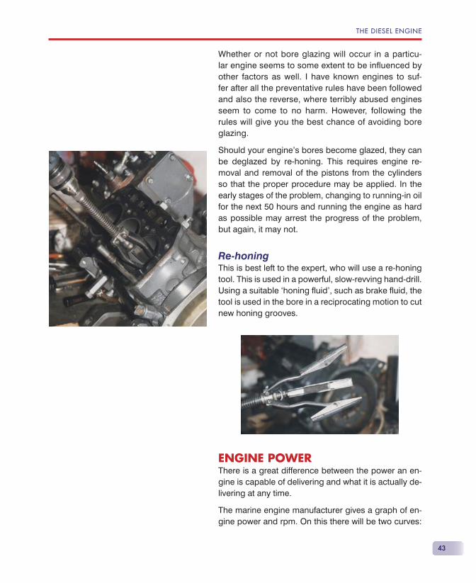
Should your engine’s bores become glazed, they can be deglazed by re-honing. This requires engine re-moval and removal of the pistons from the cylinders so that the proper procedure may be applied. In the early stages of the problem, changing to running-in oil for the next 50 hours and running the engine as hard as possible may arrest the progress of the problem, but again, it may not.
Re-honingThis is best left to the expert, who will use a re-honing tool. This is used in a powerful, slow-revving hand-drill. Using a suitable ‘honing fl uid’, such as brake fl uid, the tool is used in the bore in a reciprocating motion to cut new honing grooves.
ENGINE POWERThere is a great difference between the power an en-gine is capable of delivering and what it is actually de-livering at any time.
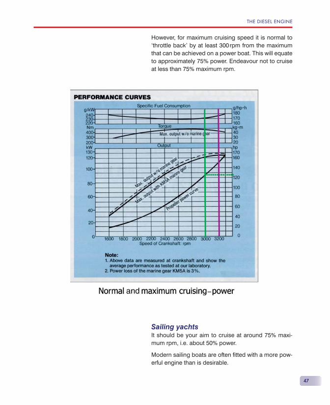
The marine engine manufacturer gives a graph of en-gine power and rpm. On this there will be two curves:
44
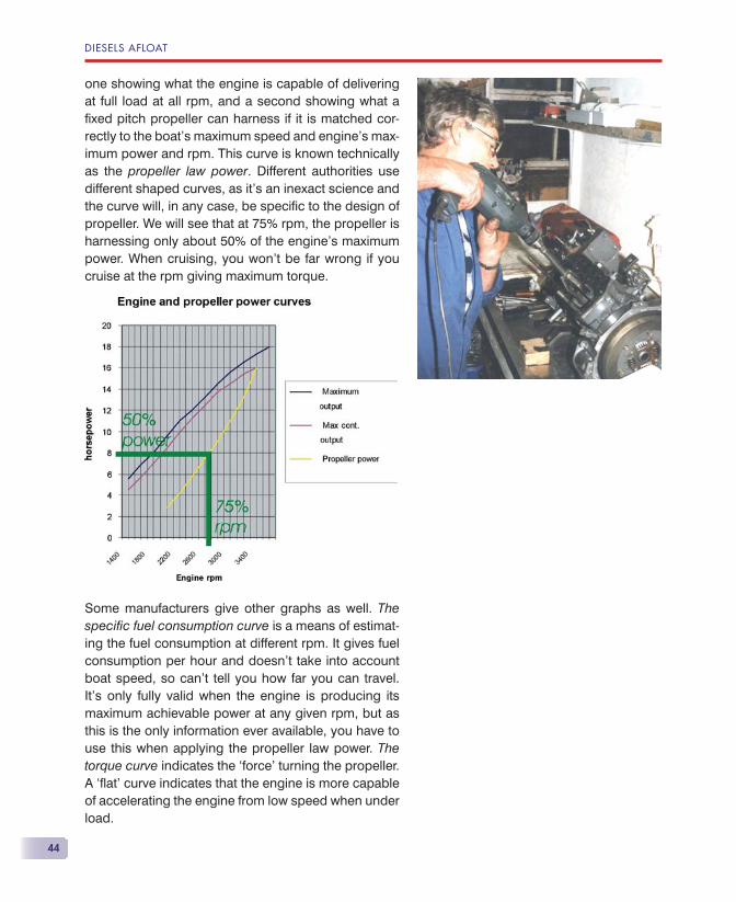
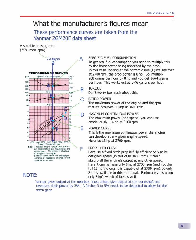
one showing what the engine is capable of delivering at full load at all rpm, and a second showing what a fi xed pitch propeller can harness if it is matched cor-rectly to the boat’s maximum speed and engine’s max-imum power and rpm. This curve is known technically as the propeller law power. Different authorities use different shaped curves, as it’s an inexact science and the curve will, in any case, be specifi c to the design of propeller. We will see that at 75% rpm, the propeller is harnessing only about 50% of the engine’s maximum power. When cruising, you won’t be far wrong if you cruise at the rpm giving maximum torque.
Some manufacturers give other graphs as well. The specifi c fuel consumption curve is a means of estimat-ing the fuel consumption at different rpm. It gives fuel consumption per hour and doesn’t take into account boat speed, so can’t tell you how far you can travel. It’s only fully valid when the engine is producing its maximum achievable power at any given rpm, but as this is the only information ever available, you have to use this when applying the propeller law power. The torque curve indicates the ‘force’ turning the propeller. A ‘fl at’ curve indicates that the engine is more capable of accelerating the engine from low speed when under load.
DIESELS AFLOAT
THE DIESEL ENGINE
45
DIESELS AFLOAT
46
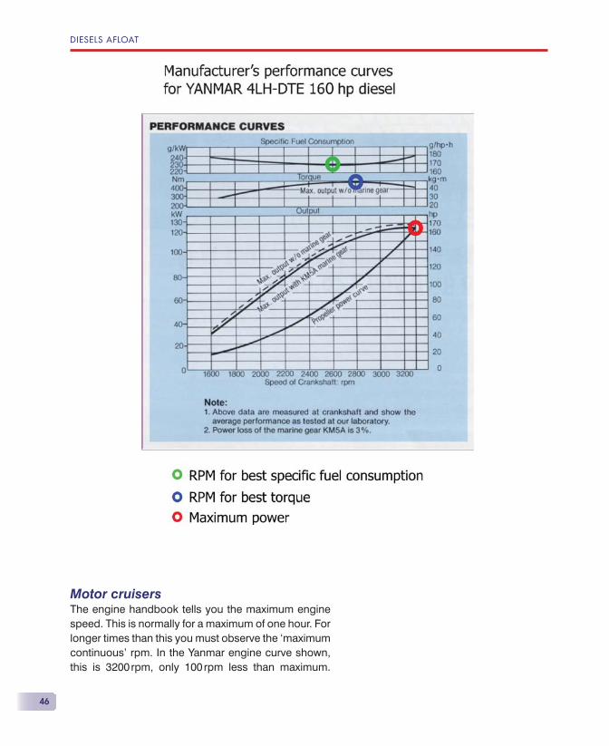
Motor cruisersThe engine handbook tells you the maximum engine speed. This is normally for a maximum of one hour. For longer times than this you must observe the ‘maximum continuous’ rpm. In the Yanmar engine curve shown, this is 3200 rpm, only 100 rpm less than maximum.
THE DIESEL ENGINE
47
However, for maximum cruising speed it is normal to ‘throttle back’ by at least 300 rpm from the maximum that can be achieved on a power boat. This will equate to approximately 75% power. Endeavour not to cruise at less than 75% maximum rpm.
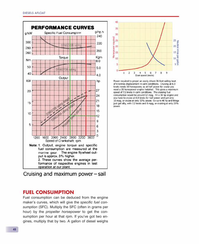
Sailing yachtsIt should be your aim to cruise at around 75% maxi-mum rpm, i.e. about 50% power.
Modern sailing boats are often fi tted with a more pow-erful engine than is desirable.
DIESELS AFLOAT
48
FUEL CONSUMPTIONFuel consumption can be deduced from the engine maker’s curves, which will give the specifi c fuel con-sumption (SFC). Multiply the SFC (often in grams per hour) by the propeller horsepower to get the con-sumption per hour at that rpm. If you’ve got two en-gines, multiply that by two. A gallon of diesel weighs
THE DIESEL ENGINE
49
about 8 lbs — about 4.2 kg (4200 g) and there are about 4.5 litres to a gallon, so you can do the sums in your units of choice.
There’s a very convenient rule of thumb, so you don’t need to get involved with the graphs. A diesel engine uses around 5 gallons per hour for every 100 horse-power. If you cruise at 75% rpm, that’s about 50% maximum power. So, for every 100 rated (maximum) horsepower, you should use two and a half gallons per hour at cruising rpm. If you average much less than that, you are not loading your engine really suffi ciently.
OPERATION OF THE ENGINEYou can prolong the engine’s life and ensure maxi-mum reliability by operating it correctly.
• Warm the engine up for only a couple of minutes if you are initially going to use only low power — you need 60 �C for full power.
• Once you have started the engine, don’t stop it until the engine is warm (about 10 minutes or so).
• Run the engine under load — ideally cruise at around 75% rpm on a displacement boat.
• Planing boats will need to be cruised at around 300 rpm less than maximum to obtain optimum per-formance.
• Open the ‘throttle’ slowly.
• When changing gear, pause in neutral (count 1 sec-ond when in neutral).
• On a twin engine boat, if forced to run at slow speed, run on one engine if possible.
• Run the engine at idle for a couple of minutes prior to shutting it down, but don’t leave it running while you tidy up the boat.
READ THE BOOKMen tend not to read instruction books, yet your diesel engine handbook contains essential information and
DIESELS AFLOAT
50
will not take long to read. I have come across a huge number of Volvo Penta 2000 series engine owners who are completely unaware of the correct cold start procedure, due entirely to their unwillingness to read the book.
A few questions may well illustrate the point:
• What is the cold start procedure for your engine?
• When sailing should you lock the prop shaft?
• How long should you remain in neutral when chang-ing from forward to reverse?
• What is the normal oil pressure?
• What is the normal water temperature?
• Do you have any engine anodes; if so, where are they?
• What engine oil and gearbox oil should be used — are they different?
• Where should you check the cooling water level?
• Should the engine alarm sound when you stop the engine?
WHERE IT’S ALL GOINGWe saw at the start of the book how simple the con-cept of the diesel engine is. Indeed, for many years the diesel maintained this simplicity, so that maintenance, troubleshooting and repair were comparatively easy.
Today, marine diesels of up to about 50 hp retain this simplicity, but from then up, complexity is added for the sake of greater effi ciency, greater power from small packages and better emission control, so that today’s larger engines are diffi cult and expensive to maintain, diffi cult to troubleshoot and expensive to repair.
For the impecunious or DIY yachtsman, or those stray-ing from places where repair facilities abound, this de-cline in simplicity will become more burdensome.
51
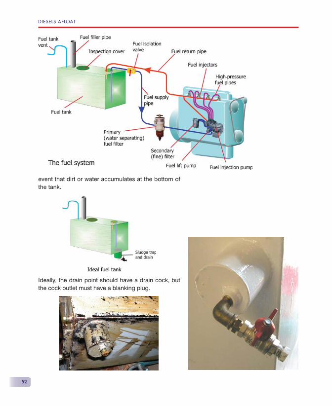
The fuel system comprises everything from the boat’s fuel tank to the engine’s fuel injector(s).
There are two distinct parts of the fuel system: that installed by the boat builder and that attached to the engine. The tank, primary fi lter and all the pipe work to and from the engine are designed and installed by the boat builder. Sometimes they don’t make a very good job. On older boats, you may fi nd modifi cations to this part of the system, so investigate it thoroughly to see if you need to bring it up to scratch. Generally, apart from routine servicing and fair wear and tear, there should be little trouble from anything supplied with the engine.
THE FUEL TANKModern fuel tanks tend to have all their connections at the top of the tank. There seem to be two reasons for this. The fi rst is the mistaken belief that this is re-quired by the various regulating bodies — this really applies only to inland waterways; the second is that it makes life easier for the boat builder. Ideally, the fuel tank should have a sludge/dirt trap at the lowest part of the tank. This will have its own drain point in the
The Fuel System
DIESELS AFLOAT
52
event that dirt or water accumulates at the bottom of the tank.
Ideally, the drain point should have a drain cock, but the cock outlet must have a blanking plug.

THE FUEL SYSTEM
53
The next best solution to the dirty tank problem is to have a hatch in the top of the tank to allow cleaning. Unfortunately, many boat builders omit even this, ei-ther to save money or because it would be inacces-sible anyway.
It is generally recommended that fuel tanks should be cleaned every fi ve years. On most boats it is diffi cult, if not impossible, to remove the fuel tank, unlike on the illustrated Westerly, which, as you can see, also has a sludge trap.
The fuel tank may be made of mild steel, stainless steel or polypropylene.
• Mild steel is cheap and easy to weld, but suffers from internal and external corrosion.
• Stainless steel doesn’t suffer from corrosion, but the welds can suffer from crevice corrosion and the welds are the weak point of this material. They are more expensive.
• Polypropylene is robust, is translucent, so you can see the contents, and it doesn’t corrode. Cost is much the same as stainless steel. It is my material of choice.
Tanks bigger than about 20 gallons (90 litres) need to have baffl es fi tted to reduce the ‘sloshing around’ of the fuel inside. The position of the baffl es can be seen clearly on the illustrated mild steel tank ready for repainting.
DIESELS AFLOAT
54
Draining the tank using the engine supply pipe will not empty the tank as the supply pipe doesn’t reach the bottom of the tank. This is to prevent the supply pipe picking up dirt from the bottom, but of course this is effective only in still water. At sea, any dirt will be shaken up.
It’s been reported that some tank makers have fi tted a strainer to the supply pipe, inside the tank. Owners of such tanks will be unaware of its existence and may be unable to clean it should it become blocked.
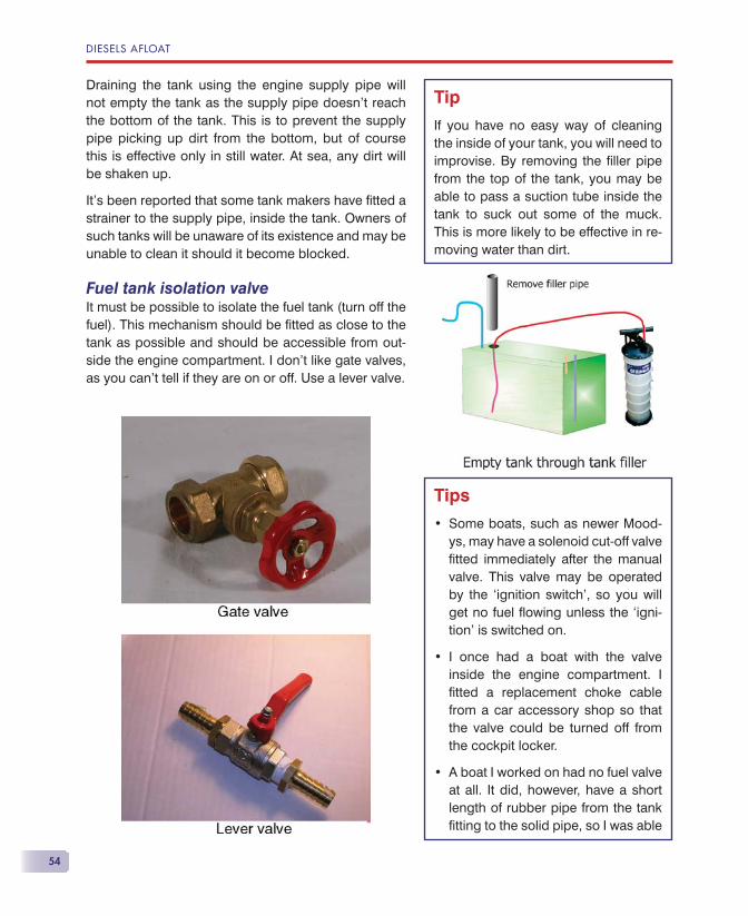
Fuel tank isolation valveIt must be possible to isolate the fuel tank (turn off the fuel). This mechanism should be fi tted as close to the tank as possible and should be accessible from out-side the engine compartment. I don’t like gate valves, as you can’t tell if they are on or off. Use a lever valve.
Tip
If you have no easy way of cleaning the inside of your tank, you will need to improvise. By removing the fi ller pipe from the top of the tank, you may be able to pass a suction tube inside the tank to suck out some of the muck. This is more likely to be effective in re-moving water than dirt.
Tips
Some boats, such as newer Mood-ys, may have a solenoid cut-off valve fi tted immediately after the manual valve. This valve may be operated by the ‘ignition switch’, so you will get no fuel fl owing unless the ‘igni-tion’ is switched on.
I once had a boat with the valve inside the engine compartment. I fi tted a replacement choke cable from a car accessory shop so that the valve could be turned off from the cockpit locker.
A boat I worked on had no fuel valve at all. It did, however, have a short length of rubber pipe from the tank fi tting to the solid pipe, so I was able
•
•
•
THE FUEL SYSTEM
55
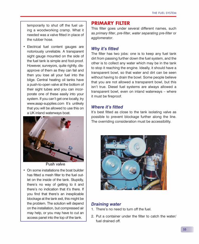
PRIMARY FILTERThis fi lter goes under several different names, such as primary fi lter, pre-fi lter, water separating pre-fi lter or agglomerator.
Why it’s fi ttedThe fi lter has two jobs: one is to keep any fuel tank dirt from passing further down the fuel system, and the other is to collect any water which may be in the tank to stop it reaching the engine. Ideally, it should have a transparent bowl, so that water and dirt can be seen without having to drain the bowl. Some people believe that you are not allowed a transparent bowl, but this isn’t true. Diesel fuel systems are always allowed a transparent bowl, even on inland waterways — where it must be fi reproof.
Where it’s fi ttedIt’s best fi tted as close to the tank isolating valve as possible to prevent blockage further along the line. The overriding consideration must be accessibility.
Draining waterThere’s no need to turn off the fuel.
Put a container under the fi lter to catch the water/fuel drained off.
1.
2.
temporarily to shut off the fuel us-ing a woodworking cramp. What it needed was a valve fi tted in place of the rubber hose.
Electrical fuel content gauges are notoriously unreliable. A transparent sight gauge mounted on the side of the fuel tank is simple and fool-proof. However, surveyors, quite rightly, dis-approve of them as they can fail and then you lose all your fuel into the bilge. Central heating oil tanks have a push-to-open valve at the bottom of their sight tubes and you can incor-porate one of these easily into your system. If you can’t get one locally, try www.asap-supplies.com It’s unlikely that you will be allowed to use this on a UK inland waterways boat.
On some installations the boat builder has fi tted a mesh fi lter to the fuel out-let on the inside of the tank. Stupidly, there’s no way of getting to it and there’s no indication that it’s there. If you fi nd that there’s an inexplicable blockage at the tank exit, this might be the problem. The solution will depend on the installation, but compressed air may help, or you may have to cut an access panel into the top of the tank.
•
•
DIESELS AFLOAT
56
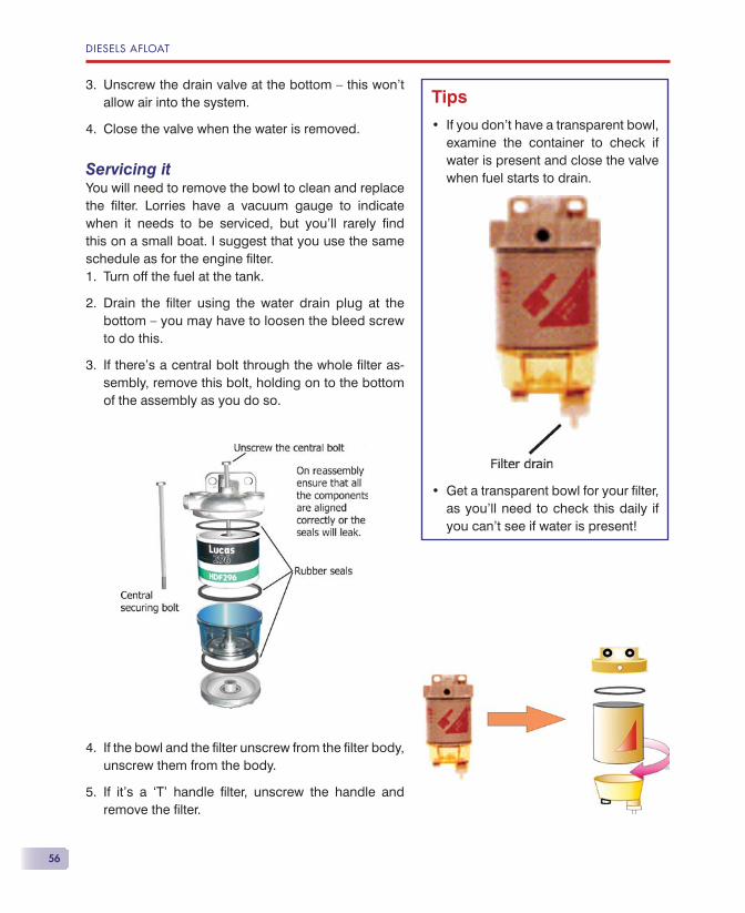
Unscrew the drain valve at the bottom — this won’t allow air into the system.
Close the valve when the water is removed.
Servicing itYou will need to remove the bowl to clean and replace the fi lter. Lorries have a vacuum gauge to indicate when it needs to be serviced, but you’ll rarely fi nd this on a small boat. I suggest that you use the same schedule as for the engine fi lter.
Turn off the fuel at the tank.
Drain the fi lter using the water drain plug at the bottom — you may have to loosen the bleed screw to do this.
If there’s a central bolt through the whole fi lter as-sembly, remove this bolt, holding on to the bottom of the assembly as you do so.
If the bowl and the fi lter unscrew from the fi lter body, unscrew them from the body.
If it’s a ‘T’ handle fi lter, unscrew the handle and remove the fi lter.
3.
4.
1.
2.
3.
4.
5.
Tips
If you don’t have a transparent bowl, examine the container to check if water is present and close the valve when fuel starts to drain.
Get a transparent bowl for your fi lter, as you’ll need to check this daily if you can’t see if water is present!
•
•
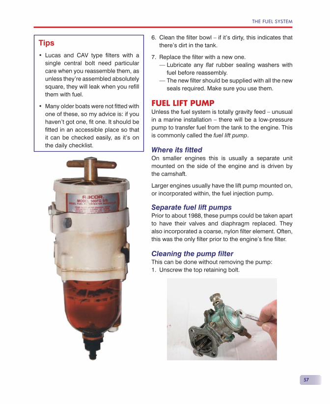
THE FUEL SYSTEM
57
Clean the fi lter bowl — if it’s dirty, this indicates that there’s dirt in the tank.
Replace the fi lter with a new one.– Lubricate any fl at rubber sealing washers with
fuel before reassembly.– The new fi lter should be supplied with all the new
seals required. Make sure you use them.
FUEL LIFT PUMPUnless the fuel system is totally gravity feed — unusual in a marine installation — there will be a low-pressure pump to transfer fuel from the tank to the engine. This is commonly called the fuel lift pump.
Where its fi ttedOn smaller engines this is usually a separate unit mounted on the side of the engine and is driven by the camshaft.
Larger engines usually have the lift pump mounted on, or incorporated within, the fuel injection pump.
Separate fuel lift pumpsPrior to about 1988, these pumps could be taken apart to have their valves and diaphragm replaced. They also incorporated a coarse, nylon fi lter element. Often, this was the only fi lter prior to the engine’s fi ne fi lter.
Cleaning the pump fi lterThis can be done without removing the pump:
Unscrew the top retaining bolt.
6.
7.
1.
Tips
Lucas and CAV type fi lters with a single central bolt need particular care when you reassemble them, as unless they’re assembled absolutely square, they will leak when you refi ll them with fuel.
Many older boats were not fi tted with one of these, so my advice is: if you haven’t got one, fi t one. It should be fi tted in an accessible place so that it can be checked easily, as it’s on the daily checklist.
•
•
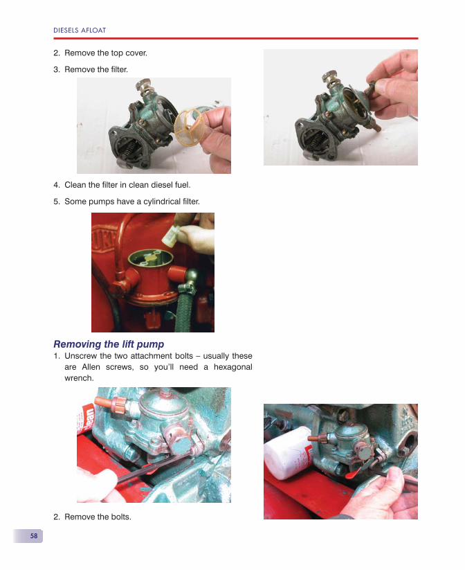
DIESELS AFLOAT
58
Remove the top cover.
Remove the fi lter.
Clean the fi lter in clean diesel fuel.
Some pumps have a cylindrical fi lter.
Removing the lift pumpUnscrew the two attachment bolts — usually these are Allen screws, so you’ll need a hexagonal wrench.
Remove the bolts.
2.
3.
4.
5.
1.
2.
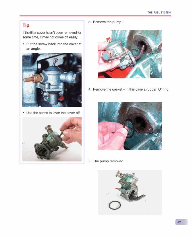
THE FUEL SYSTEM
59
Remove the pump.
Remove the gasket — in this case a rubber ‘O’ ring.
The pump removed.
3.
4.
5.
Tip
If the fi lter cover hasn’t been removed for some time, it may not come off easily.
Put the screw back into the cover at an angle.
Use the screw to lever the cover off.
•
•
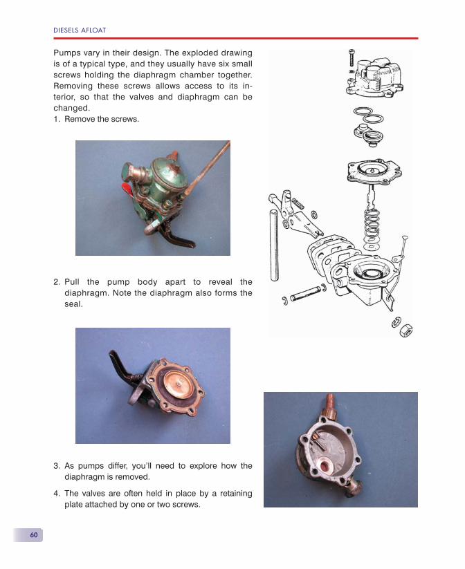
DIESELS AFLOAT
60
Pumps vary in their design. The exploded drawing is of a typical type, and they usually have six small screws holding the diaphragm chamber together. Removing these screws allows access to its in-terior, so that the valves and diaphragm can be changed.
Remove the screws.
Pull the pump body apart to reveal the diaphragm. Note the diaphragm also forms the seal.
As pumps differ, you’ll need to explore how the diaphragm is removed.
The valves are often held in place by a retaining plate attached by one or two screws.
1.
2.
3.
4.
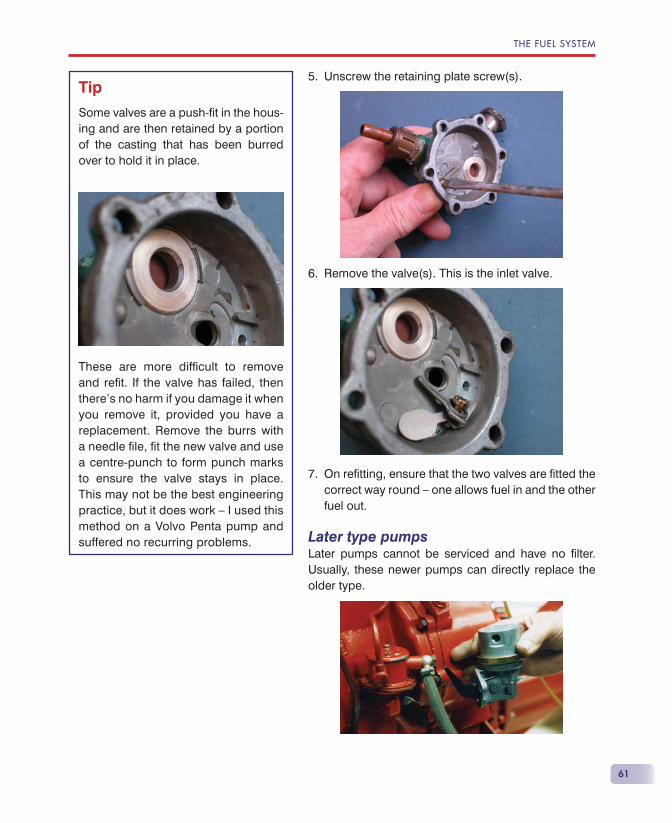
THE FUEL SYSTEM
61
Unscrew the retaining plate screw(s).
Remove the valve(s). This is the inlet valve.
On refi tting, ensure that the two valves are fi tted the correct way round — one allows fuel in and the other fuel out.
Later type pumpsLater pumps cannot be serviced and have no fi lter. Usually, these newer pumps can directly replace the older type.
5.
6.
7.
Tip
Some valves are a push-fi t in the hous-ing and are then retained by a portion of the casting that has been burred over to hold it in place.
These are more diffi cult to remove and refi t. If the valve has failed, then there’s no harm if you damage it when you remove it, provided you have a replacement. Remove the burrs with a needle fi le, fi t the new valve and use a centre-punch to form punch marks to ensure the valve stays in place. This may not be the best engineering practice, but it does work — I used this method on a Volvo Penta pump and suffered no recurring problems.
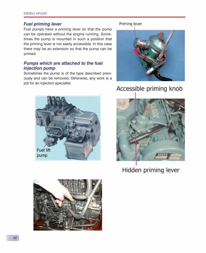
DIESELS AFLOAT
62
Fuel priming leverFuel pumps have a priming lever so that the pump can be operated without the engine running. Some-times the pump is mounted in such a position that the priming lever is not easily accessible. In this case there may be an extension so that the pump can be primed.
Pumps which are attached to the fuel injection pumpSometimes the pump is of the type described previ-ously and can be removed. Otherwise, any work is a job for an injection specialist.
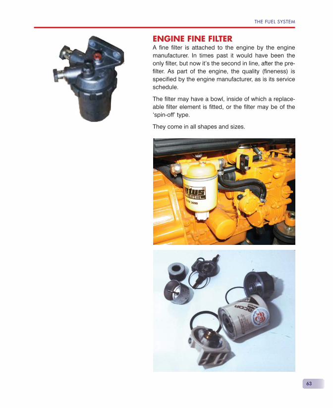
THE FUEL SYSTEM
63
ENGINE FINE FILTERA fi ne fi lter is attached to the engine by the engine manufacturer. In times past it would have been the only fi lter, but now it’s the second in line, after the pre-fi lter. As part of the engine, the quality (fi neness) is specifi ed by the engine manufacturer, as is its service schedule.
The fi lter may have a bowl, inside of which a replace-able fi lter element is fi tted, or the fi lter may be of the ‘spin-off’ type.
They come in all shapes and sizes.
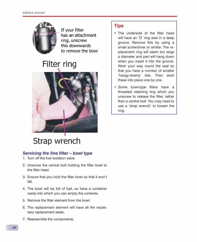
DIESELS AFLOAT
64
Servicing the fi ne fi lter — bowl typeTurn off the fuel isolation valve.
Unscrew the central bolt holding the fi lter bowl to the fi lter head.
Ensure that you hold the fi lter bowl so that it won’t fall.
The bowl will be full of fuel, so have a container ready into which you can empty the contents.
Remove the fi lter element from the bowl.
The replacement element will have all the neces-sary replacement seals.
Reassemble the components.
1.
2.
3.
4.
5.
6.
7.
Tips
The underside of the fi lter head will have an ‘O’ ring seal in a deep groove. Remove this by using a small screwdriver or similar. The re-placement ring will seem too large a diameter and part will hang down when you insert it into the groove. Work your way round the seal so that you have a number of smaller ‘hangy-downy’ bits. Then work these into place one by one.
Some bowl-type fi lters have a threaded retaining ring which you unscrew to release the fi lter, rather than a central bolt. You may need to use a ‘strap wrench’ to loosen the ring.
•
•
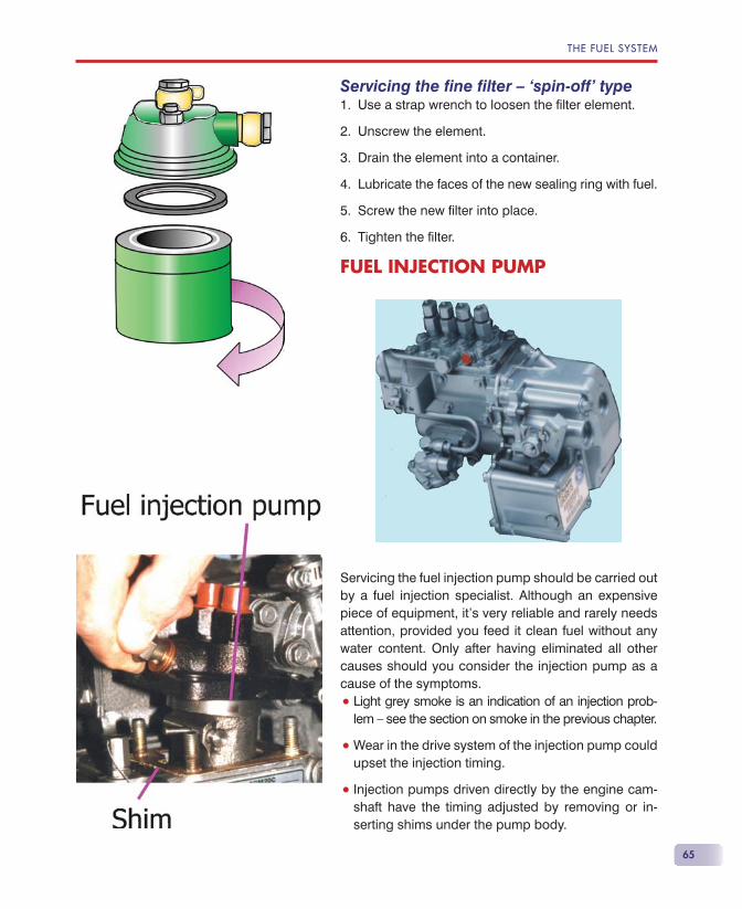
THE FUEL SYSTEM
65
Servicing the fi ne fi lter — ‘spin-off’ typeUse a strap wrench to loosen the fi lter element.
Unscrew the element.
Drain the element into a container.
Lubricate the faces of the new sealing ring with fuel.
Screw the new fi lter into place.
Tighten the fi lter.
FUEL INJECTION PUMP
Servicing the fuel injection pump should be carried out by a fuel injection specialist. Although an expensive piece of equipment, it’s very reliable and rarely needs attention, provided you feed it clean fuel without any water content. Only after having eliminated all other causes should you consider the injection pump as a cause of the symptoms.
• Light grey smoke is an indication of an injection prob-lem — see the section on smoke in the previous chapter.
• Wear in the drive system of the injection pump could upset the injection timing.
• Injection pumps driven directly by the engine cam-shaft have the timing adjusted by removing or in-serting shims under the pump body.
1.
2.
3.
4.
5.
6.
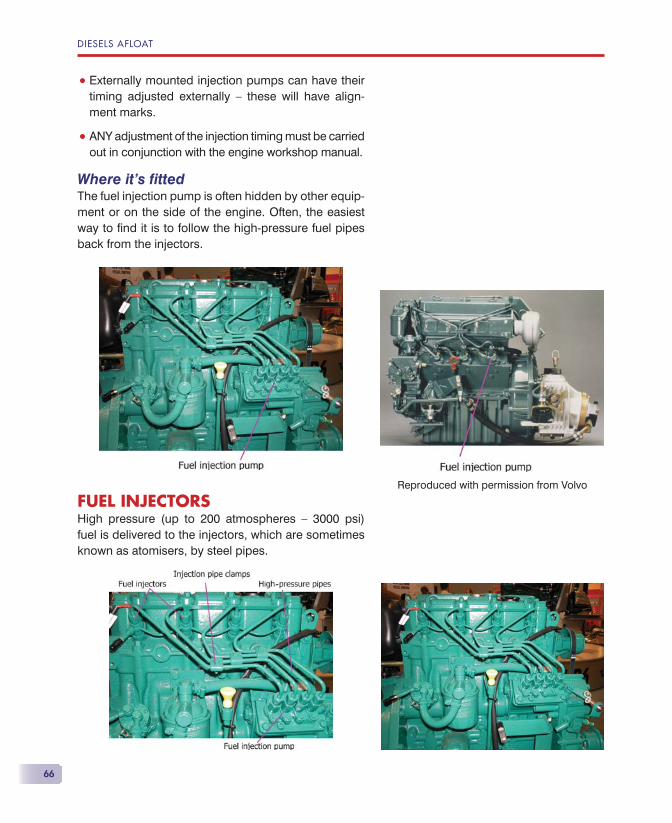
DIESELS AFLOAT
66
• Externally mounted injection pumps can have their timing adjusted externally — these will have align-ment marks.
• ANY adjustment of the injection timing must be carried out in conjunction with the engine workshop manual.
Where it’s fi ttedThe fuel injection pump is often hidden by other equip-ment or on the side of the engine. Often, the easiest way to fi nd it is to follow the high-pressure fuel pipes back from the injectors.
FUEL INJECTORSHigh pressure (up to 200 atmospheres — 3000 psi) fuel is delivered to the injectors, which are sometimes known as atomisers, by steel pipes.
Reproduced with permission from Volvo
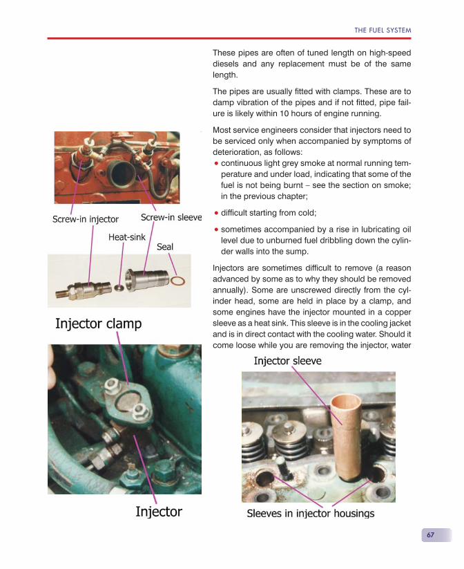
THE FUEL SYSTEM
67
These pipes are often of tuned length on high-speed diesels and any replacement must be of the same length.
The pipes are usually fi tted with clamps. These are to damp vibration of the pipes and if not fi tted, pipe fail-ure is likely within 10 hours of engine running.
Most service engineers consider that injectors need to be serviced only when accompanied by symptoms of deterioration, as follows:
• continuous light grey smoke at normal running tem-perature and under load, indicating that some of the fuel is not being burnt — see the section on smoke; in the previous chapter;
• diffi cult starting from cold;
• sometimes accompanied by a rise in lubricating oil level due to unburned fuel dribbling down the cylin-der walls into the sump.
Injectors are sometimes diffi cult to remove (a reason advanced by some as to why they should be removed annually). Some are unscrewed directly from the cyl-inder head, some are held in place by a clamp, and some engines have the injector mounted in a copper sleeve as a heat sink. This sleeve is in the cooling jacket and is in direct contact with the cooling water. Should it come loose while you are removing the injector, water
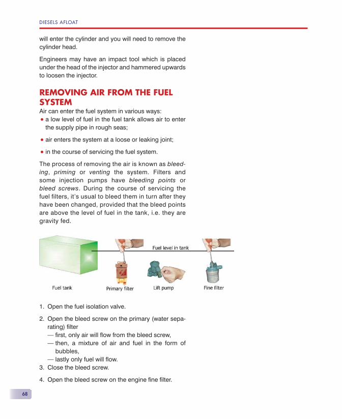
DIESELS AFLOAT
68
will enter the cylinder and you will need to remove the cylinder head.
Engineers may have an impact tool which is placed under the head of the injector and hammered upwards to loosen the injector.
REMOVING AIR FROM THE FUEL SYSTEMAir can enter the fuel system in various ways:
• a low level of fuel in the fuel tank allows air to enter the supply pipe in rough seas;
• air enters the system at a loose or leaking joint;
• in the course of servicing the fuel system.
The process of removing the air is known as bleed-ing, priming or venting the system. Filters and some injection pumps have bleeding points or bleed screws. During the course of servicing the fuel filters, it’s usual to bleed them in turn after they have been changed, provided that the bleed points are above the level of fuel in the tank, i.e. they are gravity fed.
Open the fuel isolation valve.
Open the bleed screw on the primary (water sepa-rating) fi lter– fi rst, only air will fl ow from the bleed screw,– then, a mixture of air and fuel in the form of
bubbles,– lastly only fuel will fl ow.Close the bleed screw.
Open the bleed screw on the engine fi ne fi lter.
1.
2.
3.
4.
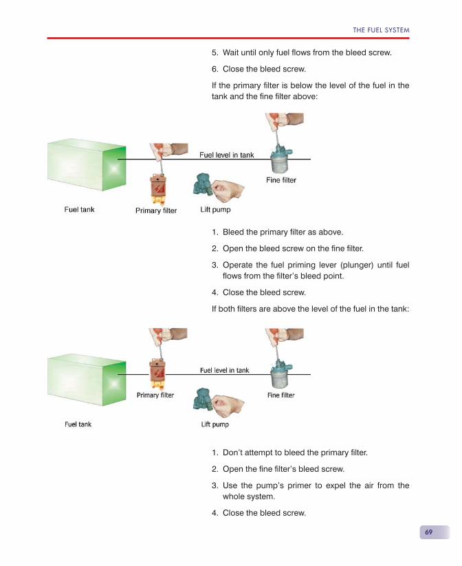
THE FUEL SYSTEM
69
Wait until only fuel fl ows from the bleed screw.
Close the bleed screw.
If the primary fi lter is below the level of the fuel in the tank and the fi ne fi lter above:
Bleed the primary fi lter as above.
Open the bleed screw on the fi ne fi lter.
Operate the fuel priming lever (plunger) until fuel fl ows from the fi lter’s bleed point.
Close the bleed screw.
If both fi lters are above the level of the fuel in the tank:
Don’t attempt to bleed the primary fi lter.
Open the fi ne fi lter’s bleed screw.
Use the pump’s primer to expel the air from the whole system.
Close the bleed screw.
5.
6.
1.
2.
3.
4.
1.
2.
3.
4.
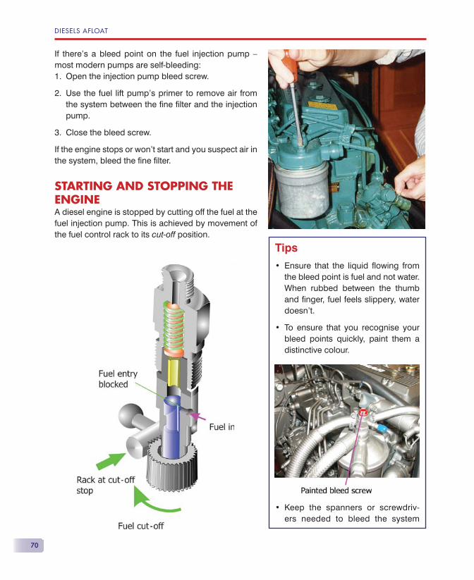
DIESELS AFLOAT
70
If there’s a bleed point on the fuel injection pump — most modern pumps are self-bleeding:
Open the injection pump bleed screw.
Use the fuel lift pump’s primer to remove air from the system between the fi ne fi lter and the injection pump.
Close the bleed screw.
If the engine stops or won’t start and you suspect air in the system, bleed the fi ne fi lter.
STARTING AND STOPPING THE ENGINEA diesel engine is stopped by cutting off the fuel at the fuel injection pump. This is achieved by movement of the fuel control rack to its cut-off position.
1.
2.
3.
Tips
Ensure that the liquid fl owing from the bleed point is fuel and not water. When rubbed between the thumb and fi nger, fuel feels slippery, water doesn’t.
To ensure that you recognise your bleed points quickly, paint them a distinctive colour.
Keep the spanners or screwdriv-ers needed to bleed the system
•
•
•
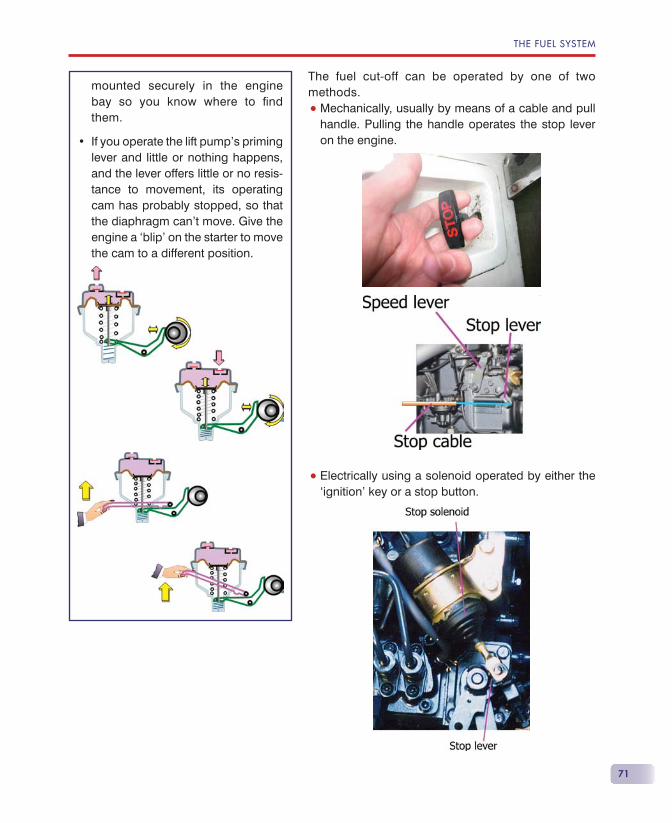
THE FUEL SYSTEM
71
The fuel cut-off can be operated by one of two methods.
• Mechanically, usually by means of a cable and pull handle. Pulling the handle operates the stop lever on the engine.
• Electrically using a solenoid operated by either the ‘ignition’ key or a stop button.
mounted securely in the engine bay so you know where to fi nd them.
If you operate the lift pump’s priming lever and little or nothing happens, and the lever offers little or no resis-tance to movement, its operating cam has probably stopped, so that the diaphragm can’t move. Give the engine a ‘blip’ on the starter to move the cam to a different position.
•
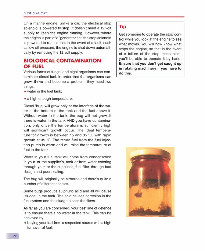
DIESELS AFLOAT
72
On a marine engine, unlike a car, the electrical stop solenoid is powered to stop. It doesn’t need a 12 volt supply to keep the engine running. However, where the engine is part of a ‘generator set’ the stop solenoid is powered to run, so that in the event of a fault, such as low oil pressure, the engine is shut down automati-cally by removing the 12 volt supply.
BIOLOGICAL CONTAMINATION OF FUELVarious forms of fungal and algal organisms can con-taminate diesel fuel. In order that the organisms can grow, thrive and become a problem, they need two things:
• water in the fuel tank;
• a high enough temperature.
Diesel ‘bug’ will grow only at the interface of the wa-ter at the bottom of the tank and the fuel above it. Without water in the tank, the bug will not grow. If there is water in the tank AND you have contamina-tion, only once the temperature is suffi ciently high will signifi cant growth occur. The ideal tempera-ture for growth is between 15 and 35 �C, with rapid growth at 35 �C. The return fuel from the fuel injec-tion pump is warm and will raise the temperature of fuel in the tank.
Water in your fuel tank will come from condensation in your, or the supplier’s, tank or from water entering through your, or the supplier’s, fuel fi ller, through bad design and poor sealing.
The bug will originally be airborne and there’s quite a number of different species.
Some bugs produce sulphuric acid and all will cause ‘sludge’ in the tank. The acid causes corrosion in the fuel system and the sludge blocks the fi lters.
As far as you are concerned, your best line of defence is to ensure there’s no water in the tank. This can be achieved by:
• buying your fuel from a respected source with a high turnover of fuel;
Tip
Get someone to operate the stop con-trol while you look at the engine to see what moves. You will now know what stops the engine, so that in the event of a failure of the stop mechanism, you’ll be able to operate it by hand. Ensure that you don’t get caught up in rotating machinery if you have to do this.

THE FUEL SYSTEM
73
• always keeping the tank topped up to prevent con-densation (especially in the winter).
The second line of defence is a water separating pre-fi lter (primary fi lter) with a transparent bowl. This allows you to inspect the bowl daily for the presence of water (and dirt).
Biocides• Bacterial contamination can be killed with a biocide,
but the dead ‘bodies’ and sludge can still cause cor-rosion and fi lter blockage.
• There are a number of different biocides available.
• If a biocide is used at every refuelling, the bugs will become resistant and greater concentrations will be needed. Eventually, it’s possible that complete re-sistance will occur.
• Use of a biocide should be restricted to an actual case of contamination, it should not be used as a prophylactic.
• Biocides are hazardous to your health.
Water removers• These substances take the water into suspension so
that the water is removed from the tank as fuel is used.
• They are used in the road transport industry to good effect.
• In a leisure boat which is used infrequently, fuel, with its cargo of water, will remain in the fuel injec-tion pump for long periods of time. I believe this is a cause of expensive corrosion in the pump and I don’t recommend their use for leisure marine fuel tanks.
Magnetic fuel conditionersI have seen no scientifi c proof of the effectiveness of magnetic (or ionising) devices.
Enzyme fuel additives• Soltron, an enzyme additive, kills 99% of the biologi-
cal contaminants and, over a succession of doses, will kill all the bugs.
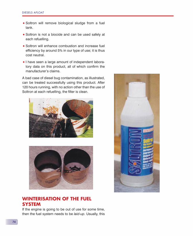
DIESELS AFLOAT
74
• Soltron will remove biological sludge from a fuel tank.
• Soltron is not a biocide and can be used safely at each refuelling.
• Soltron will enhance combustion and increase fuel effi ciency by around 5% in our type of use; it is thus cost neutral.
• I have seen a large amount of independent labora-tory data on this product, all of which confi rm the manufacturer’s claims.
A bad case of diesel bug contamination, as illustrated, can be treated successfully using this product. After 120 hours running, with no action other than the use of Soltron at each refuelling, the fi lter is clean.
WINTERISATION OF THE FUEL SYSTEMIf the engine is going to be out of use for some time, then the fuel system needs to be laid-up. Usually, this

THE FUEL SYSTEM
75
lay-up procedure is combined with the annual service on most leisure boats, because the number of hours that the engine is run is relatively low.
Fill the fuel tank.
Change the fi lters and clean their cases/bowls.
Bleed the fuel system.
Start and run the engine.
1.
2.
3.
4.

77
Only about 50% of the energy in the fuel is con-verted into engine power! The other 50% is wasted as heat energy, about half going into
the exhaust and the other half needing to be removed by the engine’s cooling system.
AIR COOLINGAir cooling has a number of advantages, amongst which are lighter weight and quicker warm-up, but where installed in an enclosed engine compart-ment, as on most boats, getting the cooling air to and from the engine raises considerable problems. Noise is also a factor as is the uncooled exhaust pipe. Leisure boats rarely have air-cooled engines these days.
WATER COOLINGThere are two forms of water cooling:
• Direct (raw water) cooling. The engine is cooled by the water in which the boat fl oats. So, if you are on the sea, seawater circulates through the engine’s cooling system.
The Engine Cooling System
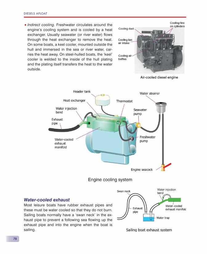
DIESELS AFLOAT
78
• Indirect cooling. Freshwater circulates around the engine’s cooling system and is cooled by a heat exchanger. Usually seawater (or river water) fl ows through the heat exchanger to remove the heat. On some boats, a keel cooler, mounted outside the hull and immersed in the sea or river water, car-ries the heat away. On steel-hulled boats, the ‘keel’ cooler is welded to the inside of the hull plating and the plating itself transfers the heat to the water outside.
Water-cooled exhaustMost leisure boats have rubber exhaust pipes and these must be water cooled so that they do not burn. Sailing boats normally have a ‘swan neck’ in the ex-haust pipe to prevent a following sea fl owing up the exhaust pipe and into the engine when the boat is sailing.
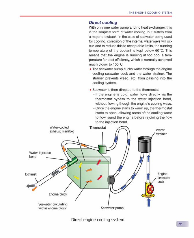
THE ENGINE COOLING SYSTEM
79
Direct coolingWith only one water pump and no heat exchanger, this is the simplest form of water cooling, but suffers from a major drawback. In the case of seawater being used for cooling, corrosion of the internal waterways will oc-cur, and to reduce this to acceptable limits, the running temperature of the coolant is kept below 60 �C. This means that the engine is running at too cool a tem-perature for best effi ciency, which is normally achieved much closer to 100 �C.
• The seawater pump sucks water through the engine cooling seawater cock and the water strainer. The strainer prevents weed, etc. from passing into the cooling system.
• Seawater is then directed to the thermostat.— If the engine is cold, water fl ows directly via the
thermostat bypass to the water injection bend, without fl owing though the engine’s cooling ways.
— Once the engine starts to warm up, the thermostat starts to open, allowing some of the cooling water to fl ow round the engine before rejoining the fl ow to the injection bend.
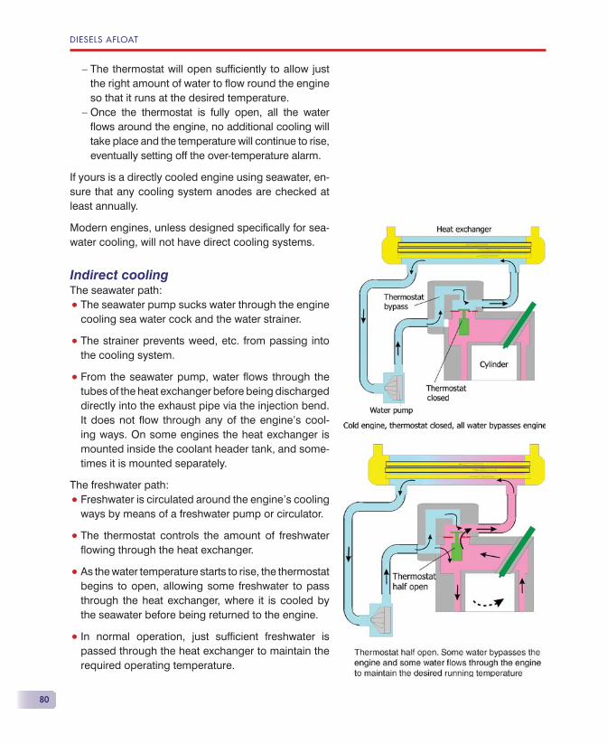
DIESELS AFLOAT
80
— The thermostat will open suffi ciently to allow just the right amount of water to fl ow round the engine so that it runs at the desired temperature.
— Once the thermostat is fully open, all the water fl ows around the engine, no additional cooling will take place and the temperature will continue to rise, eventually setting off the over-temperature alarm.
If yours is a directly cooled engine using seawater, en-sure that any cooling system anodes are checked at least annually.
Modern engines, unless designed specifi cally for sea-water cooling, will not have direct cooling systems.
Indirect coolingThe seawater path:
• The seawater pump sucks water through the engine cooling sea water cock and the water strainer.
• The strainer prevents weed, etc. from passing into the cooling system.
• From the seawater pump, water fl ows through the tubes of the heat exchanger before being discharged directly into the exhaust pipe via the injection bend. It does not fl ow through any of the engine’s cool-ing ways. On some engines the heat exchanger is mounted inside the coolant header tank, and some-times it is mounted separately.
The freshwater path:
• Freshwater is circulated around the engine’s cooling ways by means of a freshwater pump or circulator.
• The thermostat controls the amount of freshwater fl owing through the heat exchanger.
• As the water temperature starts to rise, the thermostat begins to open, allowing some freshwater to pass through the heat exchanger, where it is cooled by the seawater before being returned to the engine.
• In normal operation, just suffi cient freshwater is passed through the heat exchanger to maintain the required operating temperature.
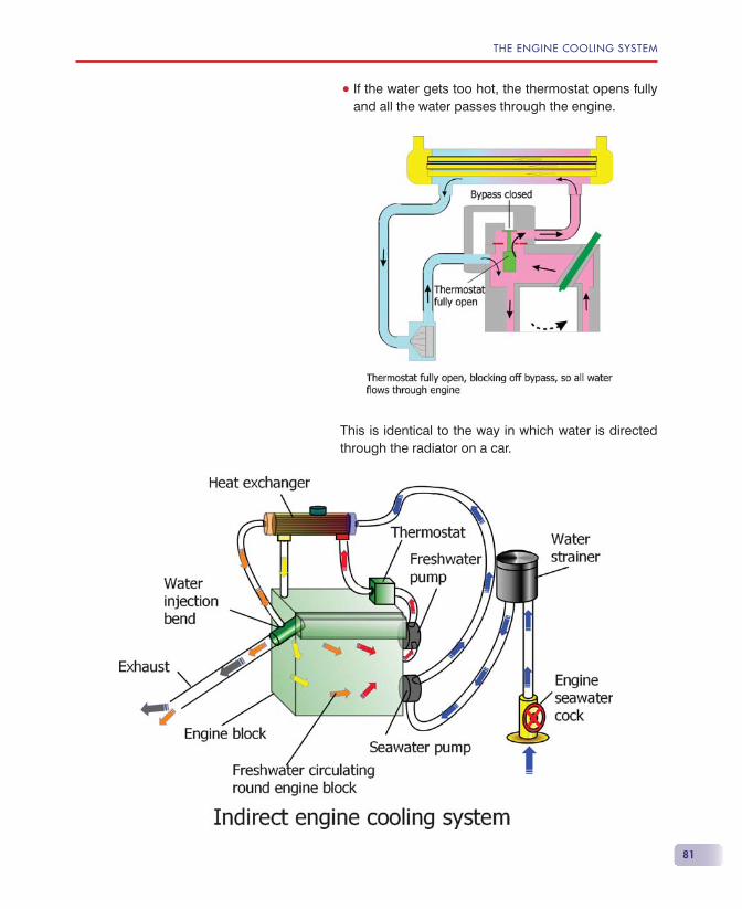
THE ENGINE COOLING SYSTEM
81
• If the water gets too hot, the thermostat opens fully and all the water passes through the engine.
This is identical to the way in which water is directed through the radiator on a car.
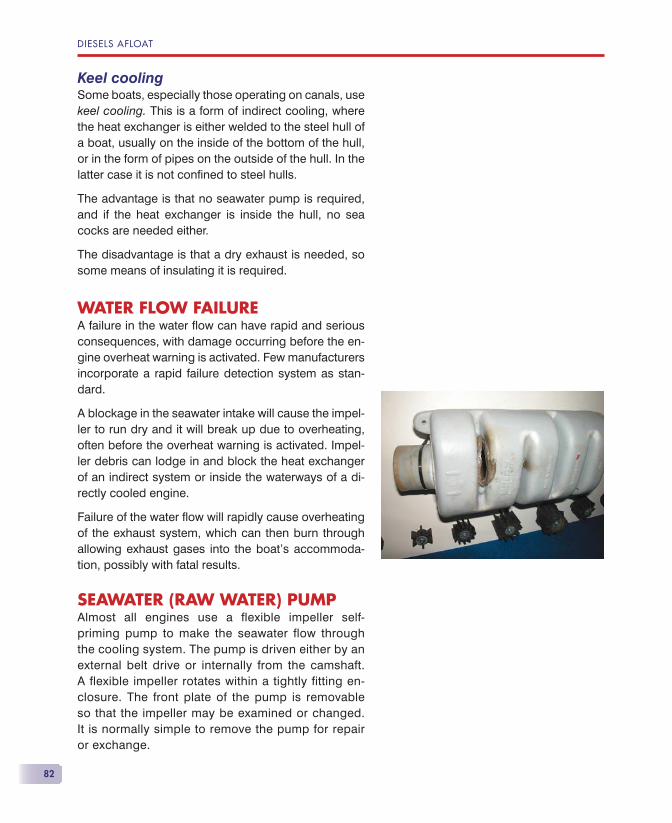
DIESELS AFLOAT
82
Keel coolingSome boats, especially those operating on canals, use keel cooling. This is a form of indirect cooling, where the heat exchanger is either welded to the steel hull of a boat, usually on the inside of the bottom of the hull, or in the form of pipes on the outside of the hull. In the latter case it is not confi ned to steel hulls.
The advantage is that no seawater pump is required, and if the heat exchanger is inside the hull, no sea cocks are needed either.
The disadvantage is that a dry exhaust is needed, so some means of insulating it is required.
WATER FLOW FAILUREA failure in the water fl ow can have rapid and serious consequences, with damage occurring before the en-gine overheat warning is activated. Few manufacturers incorporate a rapid failure detection system as stan-dard.
A blockage in the seawater intake will cause the impel-ler to run dry and it will break up due to overheating, often before the overheat warning is activated. Impel-ler debris can lodge in and block the heat exchanger of an indirect system or inside the waterways of a di-rectly cooled engine.
Failure of the water fl ow will rapidly cause overheating of the exhaust system, which can then burn through allowing exhaust gases into the boat’s accommoda-tion, possibly with fatal results.
SEAWATER (RAW WATER) PUMPAlmost all engines use a flexible impeller self-priming pump to make the seawater flow through the cooling system. The pump is driven either by an external belt drive or internally from the camshaft. A flexible impeller rotates within a tightly fitting en-closure. The front plate of the pump is removable so that the impeller may be examined or changed. It is normally simple to remove the pump for repair or exchange.
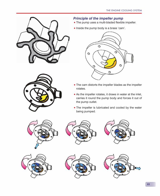
THE ENGINE COOLING SYSTEM
83
Principle of the impeller pump• The pump uses a multi-bladed fl exible impeller.
• Inside the pump body is a brass ‘cam’.
• The cam distorts the impeller blades as the impeller rotates.
• As the impeller rotates, it draws in water at the inlet, carries it round the pump body and forces it out of the pump outlet.
• The impeller is lubricated and cooled by the water being pumped.
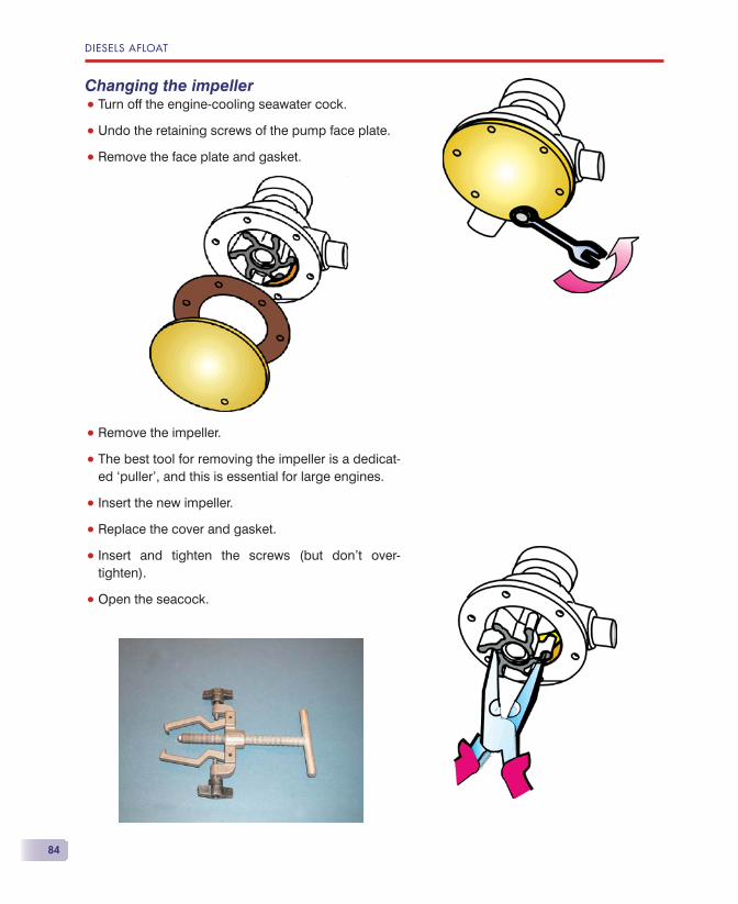
DIESELS AFLOAT
84
Changing the impeller• Turn off the engine-cooling seawater cock.
• Undo the retaining screws of the pump face plate.
• Remove the face plate and gasket.
• Remove the impeller.
• The best tool for removing the impeller is a dedicat-ed ‘puller’, and this is essential for large engines.
• Insert the new impeller.
• Replace the cover and gasket.
• Insert and tighten the screws (but don’t over-tighten).
• Open the seacock.
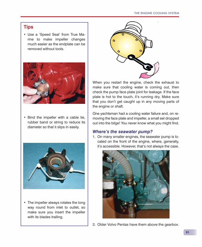
THE ENGINE COOLING SYSTEM
85
When you restart the engine, check the exhaust to make sure that cooling water is coming out, then check the pump face plate joint for leakage. If the face plate is hot to the touch, it’s running dry. Make sure that you don’t get caught up in any moving parts of the engine or shaft.
One yachtsman had a cooling water failure and, on re-moving the face plate and impeller, a small eel dropped out into the bilge! You never know what you might fi nd.
Where’s the seawater pump?On many smaller engines, the seawater pump is lo-cated on the front of the engine, where, generally, it’s accessible. However, that’s not always the case.
Older Volvo Pentas have them above the gearbox.
1.
2.
Tips
Use a ‘Speed Seal’ from True Ma-rine to make impeller changes much easier as the endplate can be removed without tools.
Bind the impeller with a cable tie, rubber band or string to reduce its diameter so that it slips in easily.
The impeller always rotates the long way round from inlet to outlet, so make sure you insert the impeller with its blades trailing.
•
•
•
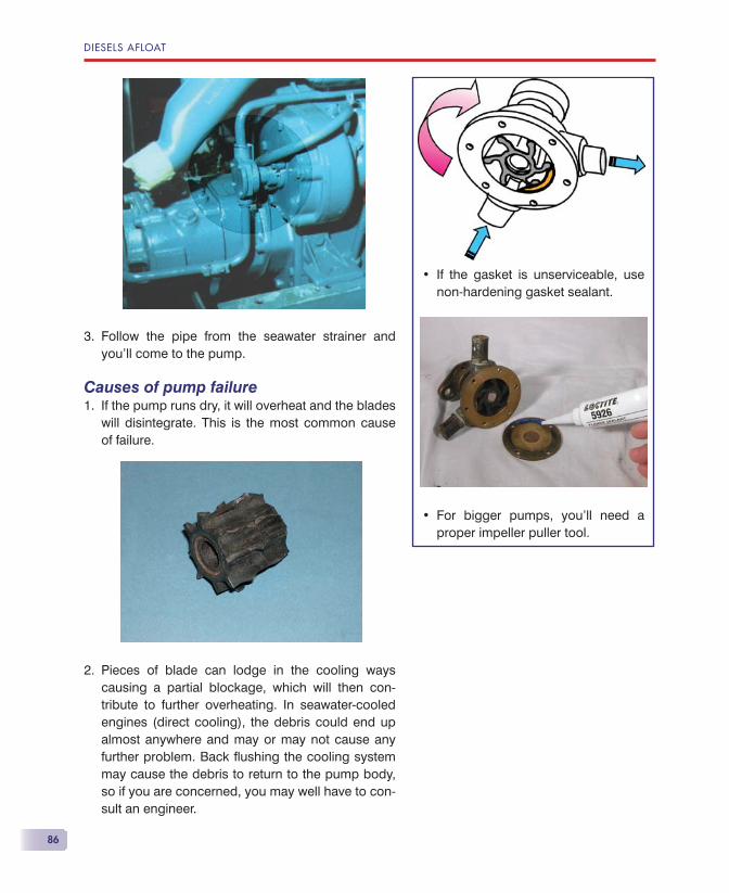
DIESELS AFLOAT
86
Follow the pipe from the seawater strainer and you’ll come to the pump.
Causes of pump failureIf the pump runs dry, it will overheat and the blades will disintegrate. This is the most common cause of failure.
Pieces of blade can lodge in the cooling ways causing a partial blockage, which will then con-tribute to further overheating. In seawater-cooled engines (direct cooling), the debris could end up almost anywhere and may or may not cause any further problem. Back fl ushing the cooling system may cause the debris to return to the pump body, so if you are concerned, you may well have to con-sult an engineer.
3.
1.
2.
If the gasket is unserviceable, use non-hardening gasket sealant.
For bigger pumps, you’ll need a proper impeller puller tool.
•
•
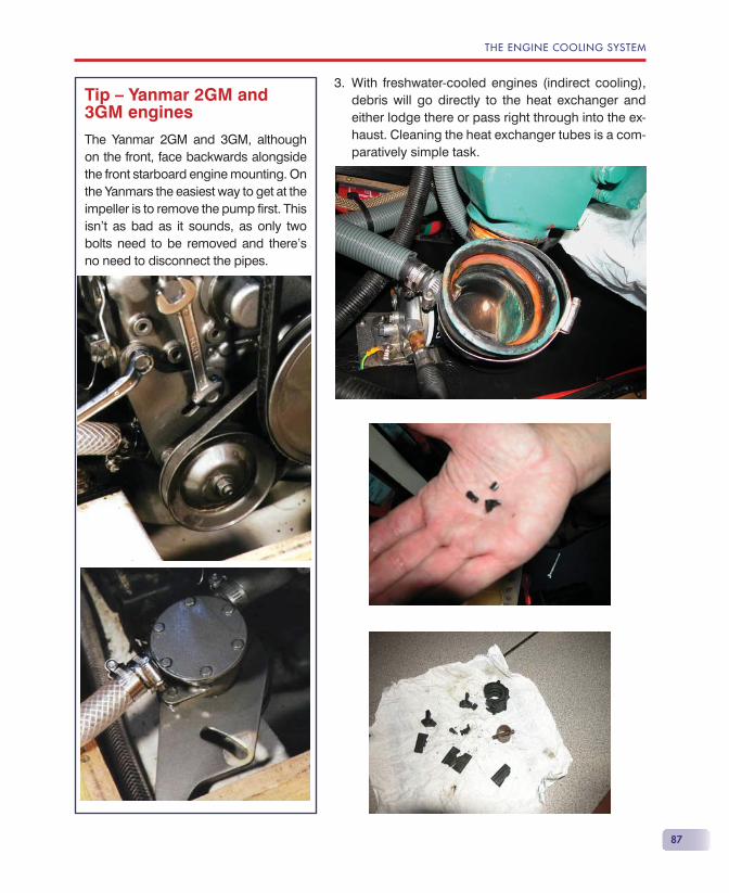
THE ENGINE COOLING SYSTEM
87
With freshwater-cooled engines (indirect cooling), debris will go directly to the heat exchanger and either lodge there or pass right through into the ex-haust. Cleaning the heat exchanger tubes is a com-paratively simple task.
3.Tip — Yanmar 2GM and 3GM engines
The Yanmar 2GM and 3GM, although on the front, face backwards alongside the front starboard engine mounting. On the Yanmars the easiest way to get at the impeller is to remove the pump fi rst. This isn’t as bad as it sounds, as only two bolts need to be removed and there’s no need to disconnect the pipes.
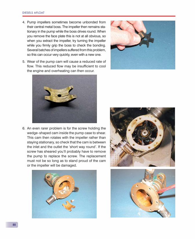
DIESELS AFLOAT
88
Pump impellers sometimes become unbonded from their central metal boss. The impeller then remains sta-tionary in the pump while the boss drives round. When you remove the face plate this is not at all obvious, so when you extract the impeller, try turning the impeller while you fi rmly grip the boss to check the bonding. Several batches of impellers suffered from this problem, so this can occur very quickly, even with a new one.
Wear of the pump cam will cause a reduced rate of fl ow. This reduced fl ow may be insuffi cient to cool the engine and overheating can then occur.
An even rarer problem is for the screw holding the wedge—shaped cam inside the pump case to shear. This cam then rotates with the impeller rather than staying stationary, so check that the cam is between the inlet and the outlet the ‘short way round’. If the screw has sheared you’ll probably have to remove the pump to replace the screw. The replacement must not be so long as to stand proud of the cam or the impeller will be damaged.
4.
5.
6.
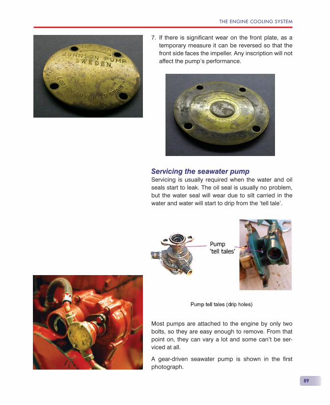
THE ENGINE COOLING SYSTEM
89
If there is signifi cant wear on the front plate, as a temporary measure it can be reversed so that the front side faces the impeller. Any inscription will not affect the pump’s performance.
Servicing the seawater pumpServicing is usually required when the water and oil seals start to leak. The oil seal is usually no problem, but the water seal will wear due to silt carried in the water and water will start to drip from the ‘tell tale’.
Most pumps are attached to the engine by only two bolts, so they are easy enough to remove. From that point on, they can vary a lot and some can’t be ser-viced at all.
A gear-driven seawater pump is shown in the fi rst photograph.
7.
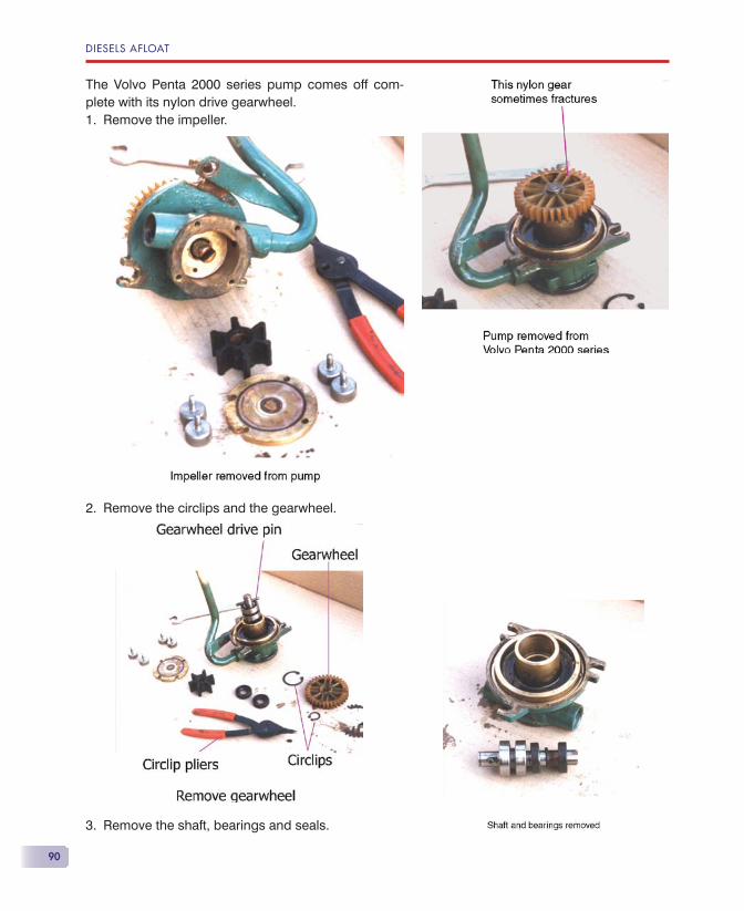
DIESELS AFLOAT
90
The Volvo Penta 2000 series pump comes off com-plete with its nylon drive gearwheel.
Remove the impeller.
Remove the circlips and the gearwheel.
Remove the shaft, bearings and seals.
1.
2.
3.
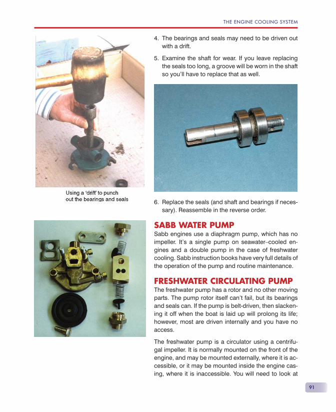
THE ENGINE COOLING SYSTEM
91
The bearings and seals may need to be driven out with a drift.
Examine the shaft for wear. If you leave replacing the seals too long, a groove will be worn in the shaft so you’ll have to replace that as well.
Replace the seals (and shaft and bearings if neces-sary). Reassemble in the reverse order.
SABB WATER PUMPSabb engines use a diaphragm pump, which has no impeller. It’s a single pump on seawater—cooled en-gines and a double pump in the case of freshwater cooling. Sabb instruction books have very full details of the operation of the pump and routine maintenance.
FRESHWATER CIRCULATING PUMPThe freshwater pump has a rotor and no other moving parts. The pump rotor itself can’t fail, but its bearings and seals can. If the pump is belt-driven, then slacken-ing it off when the boat is laid up will prolong its life; however, most are driven internally and you have no access.
The freshwater pump is a circulator using a centrifu-gal impeller. It is normally mounted on the front of the engine, and may be mounted externally, where it is ac-cessible, or it may be mounted inside the engine cas-ing, where it is inaccessible. You will need to look at
4.
5.
6.
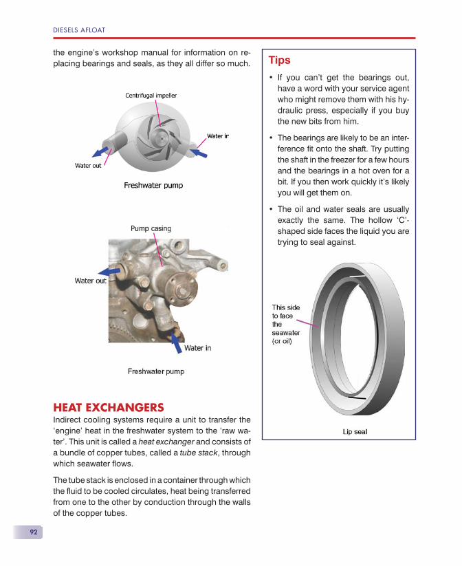
DIESELS AFLOAT
92
the engine’s workshop manual for information on re-placing bearings and seals, as they all differ so much.
HEAT EXCHANGERSIndirect cooling systems require a unit to transfer the ‘engine’ heat in the freshwater system to the ‘raw wa-ter’. This unit is called a heat exchanger and consists of a bundle of copper tubes, called a tube stack, through which seawater fl ows.
The tube stack is enclosed in a container through which the fl uid to be cooled circulates, heat being transferred from one to the other by conduction through the walls of the copper tubes.
Tips
If you can’t get the bearings out, have a word with your service agent who might remove them with his hy-draulic press, especially if you buy the new bits from him.
The bearings are likely to be an inter-ference fi t onto the shaft. Try putting the shaft in the freezer for a few hours and the bearings in a hot oven for a bit. If you then work quickly it’s likely you will get them on.
The oil and water seals are usually exactly the same. The hollow ‘C’-shaped side faces the liquid you are trying to seal against.
•
•
•
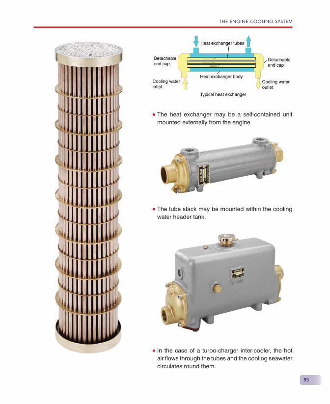
THE ENGINE COOLING SYSTEM
93
• The heat exchanger may be a self-contained unit mounted externally from the engine.
• The tube stack may be mounted within the cooling water header tank.
• In the case of a turbo-charger inter-cooler, the hot air fl ows through the tubes and the cooling seawater circulates round them.
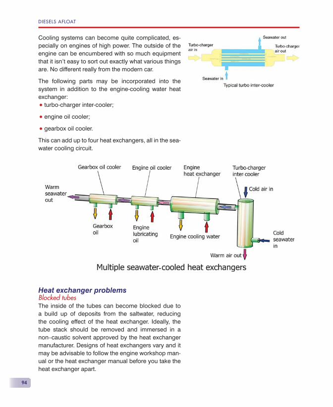
DIESELS AFLOAT
94
Cooling systems can become quite complicated, es-pecially on engines of high power. The outside of the engine can be encumbered with so much equipment that it isn’t easy to sort out exactly what various things are. No different really from the modern car.
The following parts may be incorporated into the system in addition to the engine-cooling water heat exchanger:
• turbo-charger inter-cooler;
• engine oil cooler;
• gearbox oil cooler.
This can add up to four heat exchangers, all in the sea-water cooling circuit.
Heat exchanger problemsBlocked tubesThe inside of the tubes can become blocked due to a build up of deposits from the saltwater, reducing the cooling effect of the heat exchanger. Ideally, the tube stack should be removed and immersed in a non—caustic solvent approved by the heat exchanger manufacturer. Designs of heat exchangers vary and it may be advisable to follow the engine workshop man-ual or the heat exchanger manual before you take the heat exchanger apart.
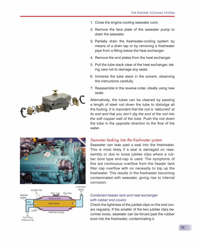
THE ENGINE COOLING SYSTEM
95
Close the engine-cooling seawater cock.
Remove the face plate of the seawater pump to drain the seawater.
Partially drain the freshwater-cooling system by means of a drain tap or by removing a freshwater pipe from a fi tting below the heat exchanger.
Remove the end plates from the heat exchanger.
Pull the tube stack clear of the heat exchanger, tak-ing care not to damage any seals.
Immerse the tube stack in the solvent, observing the instructions carefully.
Reassemble in the reverse order, ideally using new seals.
Alternatively, the tubes can be cleaned by passing a length of steel rod down the tube to dislodge all the fouling. It is important that the rod is ‘deburred’ at its end and that you don’t dig the end of the rod into the soft copper wall of the tube. Push the rod down the tube in the opposite direction to the fl ow of the water.
Seawater leaking into the freshwater systemSeawater can leak past a seal into the freshwater. This is most likely if a seal is damaged on reas-sembly or due to loose jubilee clips where a rub-ber boot type end-cap is used. The symptoms of this are continuous overflow from the header tank filler cap overflow with no necessity to top up the freshwater. This results in the freshwater becoming contaminated with seawater, giving rise to internal corrosion.
Combined header tank and heat exchangerwith rubber end coversCheck the tightness of the jubilee clips on the end cov-ers regularly. If the smaller of the two jubilee clips be-comes loose, seawater can be forced past the rubber boot into the freshwater, contaminating it.
1.
2.
3.
4.
5.
6.
7.
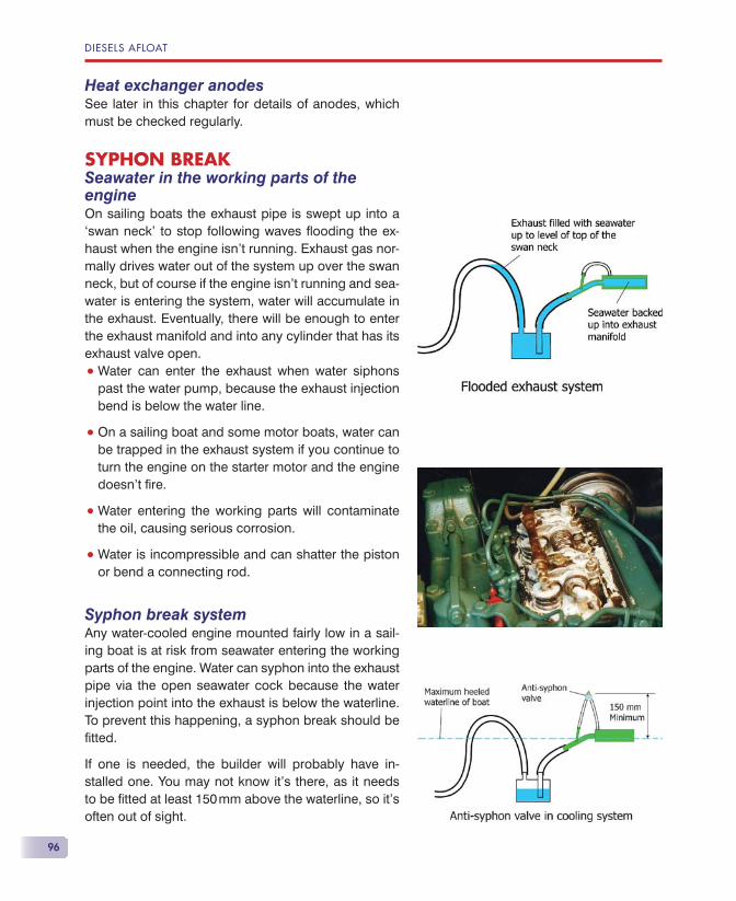
DIESELS AFLOAT
96
Heat exchanger anodesSee later in this chapter for details of anodes, which must be checked regularly.
SYPHON BREAKSeawater in the working parts of the engineOn sailing boats the exhaust pipe is swept up into a ‘swan neck’ to stop following waves fl ooding the ex-haust when the engine isn’t running. Exhaust gas nor-mally drives water out of the system up over the swan neck, but of course if the engine isn’t running and sea-water is entering the system, water will accumulate in the exhaust. Eventually, there will be enough to enter the exhaust manifold and into any cylinder that has its exhaust valve open.
• Water can enter the exhaust when water siphons past the water pump, because the exhaust injection bend is below the water line.
• On a sailing boat and some motor boats, water can be trapped in the exhaust system if you continue to turn the engine on the starter motor and the engine doesn’t fi re.
• Water entering the working parts will contaminate the oil, causing serious corrosion.
• Water is incompressible and can shatter the piston or bend a connecting rod.
Syphon break systemAny water-cooled engine mounted fairly low in a sail-ing boat is at risk from seawater entering the working parts of the engine. Water can syphon into the exhaust pipe via the open seawater cock because the water injection point into the exhaust is below the waterline. To prevent this happening, a syphon break should be fi tted.
If one is needed, the builder will probably have in-stalled one. You may not know it’s there, as it needs to be fi tted at least 150 mm above the waterline, so it’s often out of sight.
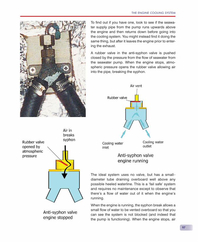
THE ENGINE COOLING SYSTEM
97
To fi nd out if you have one, look to see if the seawa-ter supply pipe from the pump runs upwards above the engine and then returns down before going into the cooling system. You might instead fi nd it doing the same thing, but after it leaves the engine prior to enter-ing the exhaust.
A rubber valve in the anti-syphon valve is pushed closed by the pressure from the fl ow of seawater from the seawater pump. When the engine stops, atmo-spheric pressure opens the rubber valve allowing air into the pipe, breaking the syphon.
The ideal system uses no valve, but has a small— diameter tube draining overboard well above any possible heeled waterline. This is a ‘fail safe’ system and requires no maintenance except to observe that there’s a fl ow of water out of it when the engine’s running.
When the engine is running, the syphon break allows a small fl ow of water to be vented overboard so that you can see the system is not blocked (and indeed that the pump is functioning). When the engine stops, air
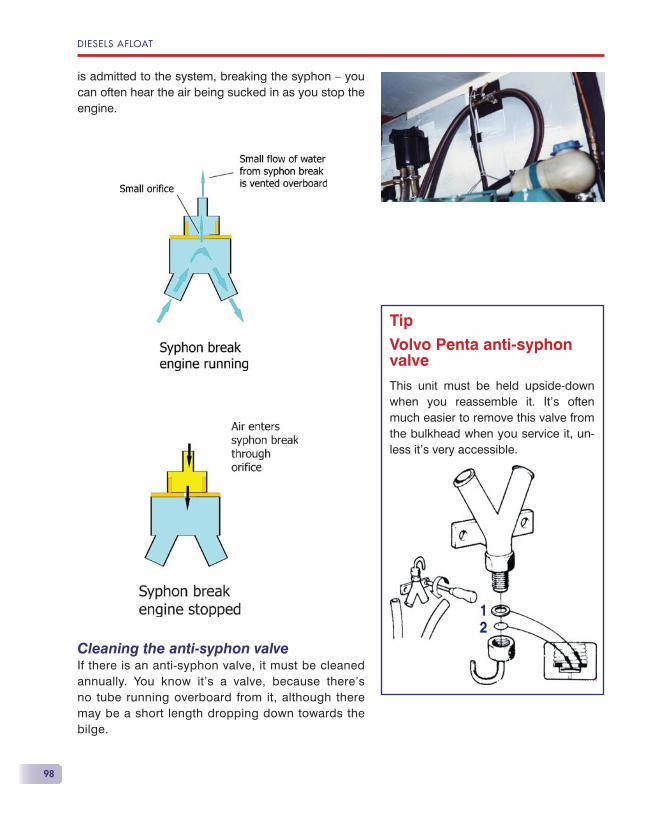
DIESELS AFLOAT
98
is admitted to the system, breaking the syphon — you can often hear the air being sucked in as you stop the engine.
Cleaning the anti-syphon valveIf there is an anti-syphon valve, it must be cleaned annually. You know it’s a valve, because there’s no tube running overboard from it, although there may be a short length dropping down towards the bilge.
Tip
Volvo Penta anti-syphon valve
This unit must be held upside-down when you reassemble it. It’s often much easier to remove this valve from the bulkhead when you service it, un-less it’s very accessible.
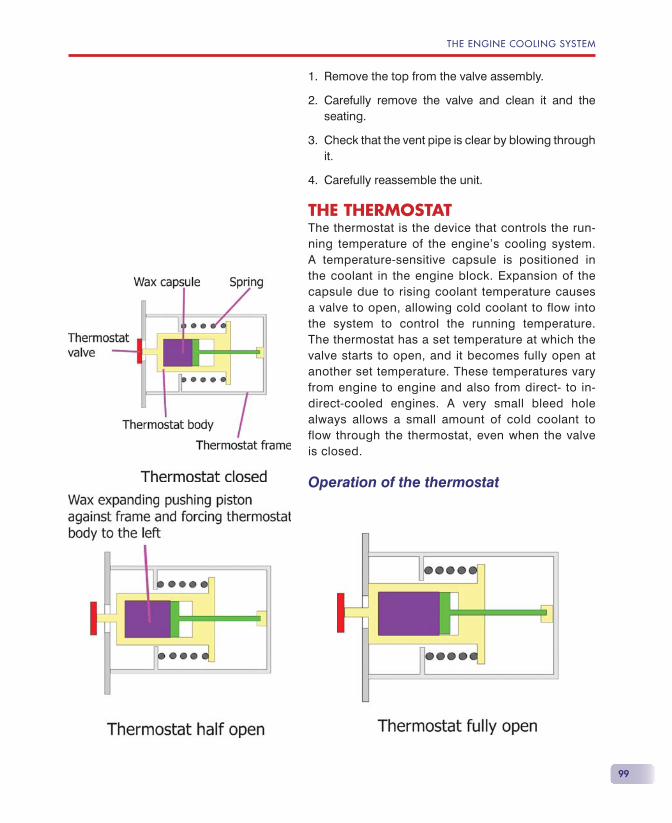
THE ENGINE COOLING SYSTEM
99
Remove the top from the valve assembly.
Carefully remove the valve and clean it and the seating.
Check that the vent pipe is clear by blowing through it.
Carefully reassemble the unit.
THE THERMOSTATThe thermostat is the device that controls the run-ning temperature of the engine’s cooling system. A temperature-sensitive capsule is positioned in the coolant in the engine block. Expansion of the capsule due to rising coolant temperature causes a valve to open, allowing cold coolant to flow into the system to control the running temperature. The thermostat has a set temperature at which the valve starts to open, and it becomes fully open at another set temperature. These temperatures vary from engine to engine and also from direct- to in-direct-cooled engines. A very small bleed hole always allows a small amount of cold coolant to flow through the thermostat, even when the valve is closed.
Operation of the thermostat
1.
2.
3.
4.
DIESELS AFLOAT
100
Direct (seawater) cooled enginesThermostats intended for use in seawater are gener-ally set to operate at around 55 �C to reduce the effects of corrosion.
• When cold, all the incoming cold water bypasses the engine and is injected directly into the exhaust.
• When the thermostat starts to open, some cold wa-ter is allowed to fl ow into the engine to mix with the hot water.
• At the designed running temperature, the thermo-stat valve continually adjusts its position to allow just suffi cient cold water into the engine to maintain the desired temperature.
• If the engine overheats, the valve opens fully to force all the cold water through the engine.
• After this point is reached, any further overheating is uncontrolled by the thermostat, which is now fully open.
Indirect (freshwater) cooled enginesThermostats intended for use in freshwater-cooled engines are generally set to operate at around 90 �C to maximise engine effi ciency, as corrosion is not a problem.
• When cold, no circulation of engine coolant occurs through the heat exchanger.
• When the temperature approaches the designed running temperature, the thermostat valve starts to open, allowing some engine coolant to fl ow through the heat exchanger.
• At the designed running temperature, the thermo-stat adjusts its position continually to maintain the desired running temperature.
• If the engine overheats, the valve is fully open and all the coolant is forced through the heat exchanger.
• After this point is reached, any further overheating is uncontrolled by the thermostat, which is now fully open.
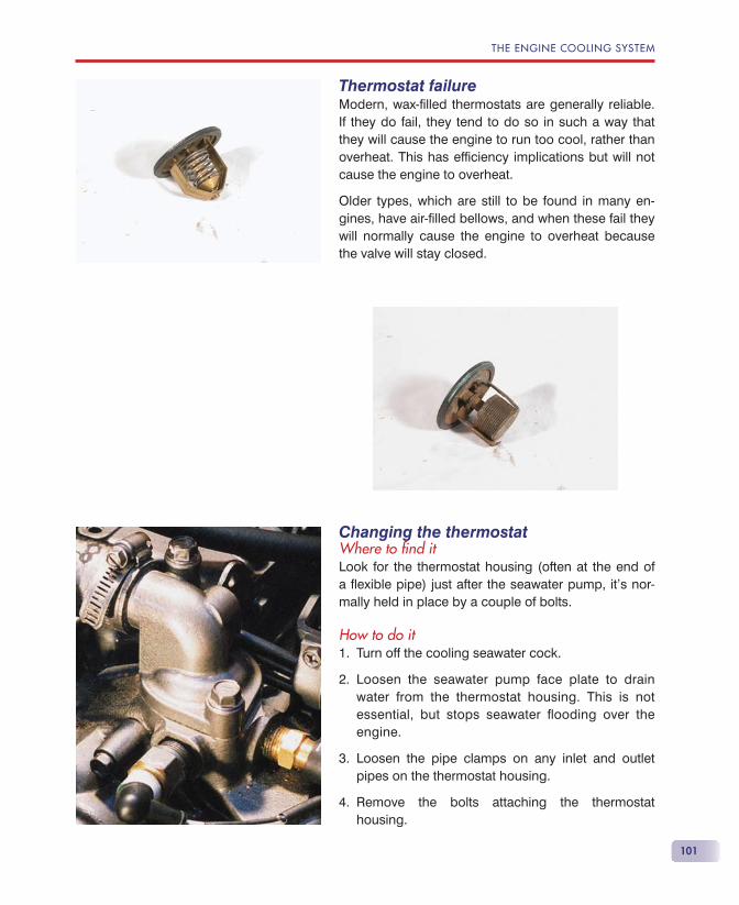
THE ENGINE COOLING SYSTEM
101
Thermostat failureModern, wax-fi lled thermostats are generally reliable. If they do fail, they tend to do so in such a way that they will cause the engine to run too cool, rather than overheat. This has effi ciency implications but will not cause the engine to overheat.
Older types, which are still to be found in many en-gines, have air-fi lled bellows, and when these fail they will normally cause the engine to overheat because the valve will stay closed.
Changing the thermostatWhere to fi nd itLook for the thermostat housing (often at the end of a fl exible pipe) just after the seawater pump, it’s nor-mally held in place by a couple of bolts.
How to do itTurn off the cooling seawater cock.
Loosen the seawater pump face plate to drain water from the thermostat housing. This is not essential, but stops seawater fl ooding over the engine.
Loosen the pipe clamps on any inlet and outlet pipes on the thermostat housing.
Remove the bolts attaching the thermostat housing.
1.
2.
3.
4.
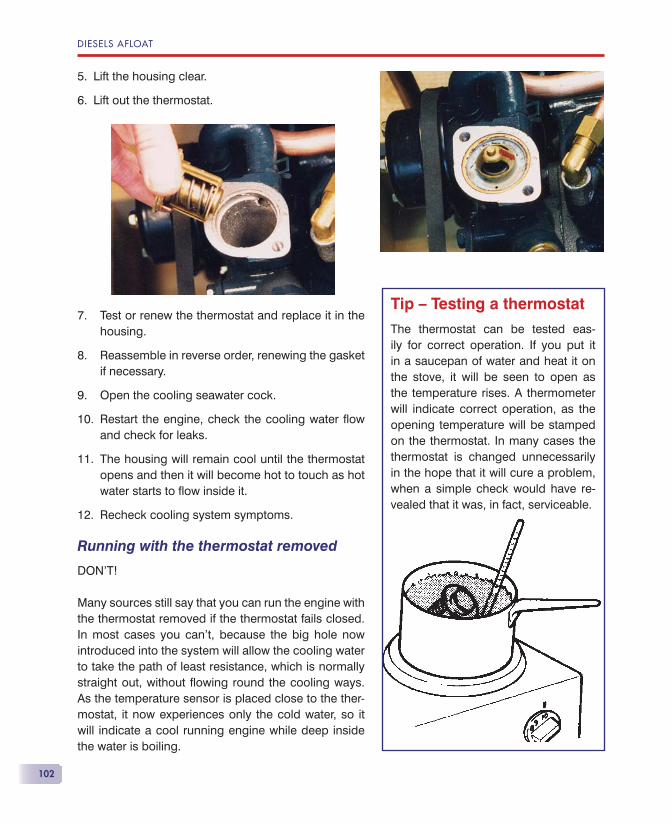
DIESELS AFLOAT
102
Lift the housing clear.
Lift out the thermostat.
Test or renew the thermostat and replace it in the housing.
Reassemble in reverse order, renewing the gasket if necessary.
Open the cooling seawater cock.
Restart the engine, check the cooling water fl ow and check for leaks.
The housing will remain cool until the thermostat opens and then it will become hot to touch as hot water starts to fl ow inside it.
Recheck cooling system symptoms.
Running with the thermostat removed
DON’T!
Many sources still say that you can run the engine with the thermostat removed if the thermostat fails closed. In most cases you can’t, because the big hole now introduced into the system will allow the cooling water to take the path of least resistance, which is normally straight out, without fl owing round the cooling ways. As the temperature sensor is placed close to the ther-mostat, it now experiences only the cold water, so it will indicate a cool running engine while deep inside the water is boiling.
5.
6.
7.
8.
9.
10.
11.
12.
Tip — Testing a thermostat
The thermostat can be tested eas-ily for correct operation. If you put it in a saucepan of water and heat it on the stove, it will be seen to open as the temperature rises. A thermometer will indicate correct operation, as the opening temperature will be stamped on the thermostat. In many cases the thermostat is changed unnecessarily in the hope that it will cure a problem, when a simple check would have re-vealed that it was, in fact, serviceable.
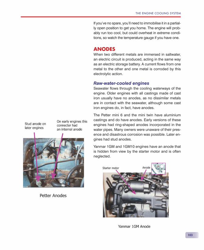
THE ENGINE COOLING SYSTEM
103
If you’ve no spare, you’ll need to immobilise it in a partial-ly open position to get you home. The engine will prob-ably run too cool, but could overheat in extreme condi-tions, so watch the temperature gauge if you have one.
ANODESWhen two different metals are immersed in saltwater, an electric circuit is produced, acting in the same way as an electric storage battery. A current fl ows from one metal to the other and one metal is corroded by this electrolytic action.
Raw-water-cooled enginesSeawater fl ows through the cooling waterways of the engine. Older engines with all castings made of cast iron usually have no anodes, as no dissimilar metals are in contact with the seawater, although some cast iron engines do, in fact, have anodes.
The Petter mini 6 and the mini twin have aluminium castings and do have anodes. Early versions of these engines had ring-shaped anodes incorporated in the water pipes. Many owners were unaware of their pres-ence and disastrous corrosion was possible. Later en-gines had stud anodes.
Yanmar 1GM and 1GM10 engines have an anode that is hidden from view by the starter motor and is often neglected.
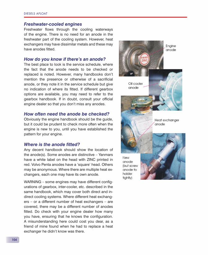
DIESELS AFLOAT
104
Freshwater-cooled enginesFreshwater fl ows through the cooling waterways of the engine. There is no need for an anode in the freshwater part of the cooling system. However, heat exchangers may have dissimilar metals and these may have anodes fi tted.
How do you know if there’s an anode?The best place to look is the service schedule, where the fact that the anode needs to be checked or replaced is noted. However, many handbooks don’t mention the presence or otherwise of a sacrifi cial anode, or they note it in the service schedule but give no indication of where its fi tted. If different gearbox options are available, you may need to refer to the gearbox handbook. If in doubt, consult your offi cial engine dealer so that you don’t miss any anodes.
How often need the anode be checked?Obviously the engine handbook should be the guide, but it could be prudent to check more often when the engine is new to you, until you have established the pattern for your engine.
Where is the anode fi tted?Any decent handbook should show the location of the anode(s). Some anodes are distinctive — Yanmars have a white label on the head with ZINC printed in red. Volvo Penta anodes have a ‘square’ head. Others may be anonymous. Where there are multiple heat ex-changers, each one may have its own anode.
WARNING — some engines may have different confi g-urations of gearbox, inter-cooler, etc. described in the same handbook, which may cover both direct and in-direct cooling systems. Where different heat exchang-ers — or a different number of heat exchangers — are covered, there may be a different number of anodes fi tted. Do check with your engine dealer how many you have, ensuring that he knows the confi guration. A misunderstanding here could cost you dear, as a friend of mine found when he had to replace a heat exchanger he didn’t know was there.
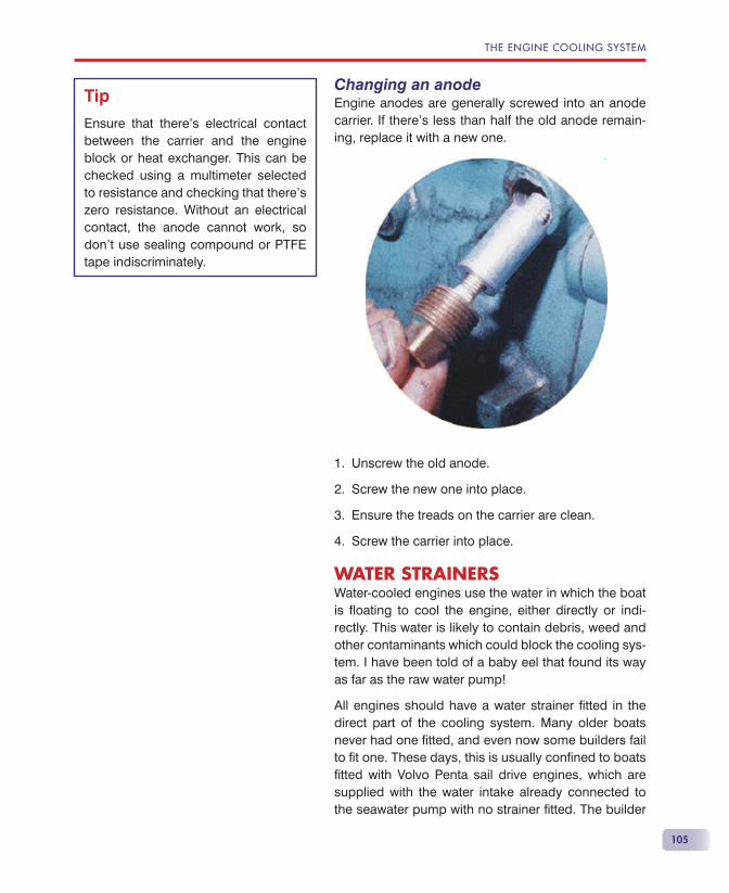
THE ENGINE COOLING SYSTEM
105
Changing an anodeEngine anodes are generally screwed into an anode carrier. If there’s less than half the old anode remain-ing, replace it with a new one.
Unscrew the old anode.
Screw the new one into place.
Ensure the treads on the carrier are clean.
Screw the carrier into place.
WATER STRAINERSWater-cooled engines use the water in which the boat is fl oating to cool the engine, either directly or indi-rectly. This water is likely to contain debris, weed and other contaminants which could block the cooling sys-tem. I have been told of a baby eel that found its way as far as the raw water pump!
All engines should have a water strainer fi tted in the direct part of the cooling system. Many older boats never had one fi tted, and even now some builders fail to fi t one. These days, this is usually confi ned to boats fi tted with Volvo Penta sail drive engines, which are supplied with the water intake already connected to the seawater pump with no strainer fi tted. The builder
1.
2.
3.
4.
Tip
Ensure that there’s electrical contact between the carrier and the engine block or heat exchanger. This can be checked using a multimeter selected to resistance and checking that there’s zero resistance. Without an electrical contact, the anode cannot work, so don’t use sealing compound or PTFE tape indiscriminately.
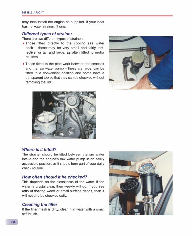
DIESELS AFLOAT
106
may then install the engine as supplied. If your boat has no water strainer, fi t one.
Different types of strainerThere are two different types of strainer:
• Those fi tted directly to the cooling sea water cock — these may be very small and fairly inef-fective, or tall and large, as often fi tted to motor cruisers.
• Those fi tted to the pipe-work between the seacock and the raw water pump — these are large, can be fi tted in a convenient position and some have a transparent top so that they can be checked without removing the ‘lid’.
Where is it fi tted?The strainer should be fi tted between the raw water intake and the engine’s raw water pump in an easily accessible position, as it should form part of your daily check routine.
How often should it be checked?This depends on the cleanliness of the water. If the water is crystal clear, then weekly will do. If you see rafts of fl oating weed or small surface debris, then it will need to be checked daily.
Cleaning the fi lterIf the fi lter mesh is dirty, clean it in water with a small stiff brush.
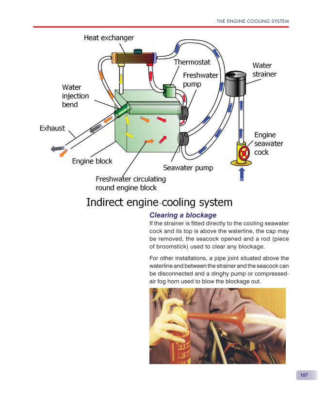
THE ENGINE COOLING SYSTEM
107
Clearing a blockageIf the strainer is fi tted directly to the cooling seawater cock and its top is above the waterline, the cap may be removed, the seacock opened and a rod (piece of broomstick) used to clear any blockage.
For other installations, a pipe joint situated above the waterline and between the strainer and the seacock can be disconnected and a dinghy pump or compressed-air fog horn used to blow the blockage out.
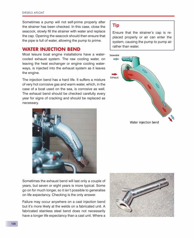
DIESELS AFLOAT
108
Sometimes a pump will not self-prime properly after the strainer has been checked. In this case, close the seacock, slowly fi ll the strainer with water and replace the cap. Opening the seacock should then ensure that the pipe is full of water, allowing the pump to prime.
WATER INJECTION BENDMost leisure boat engine installations have a water-cooled exhaust system. The raw cooling water, on leaving the heat exchanger or engine cooling water-ways, is injected into the exhaust system as it leaves the engine.
The injection bend has a hard life. It suffers a mixture of very hot corrosive gas and warm water, which, in the case of a boat used on the sea, is corrosive as well. The exhaust bend should be checked carefully every year for signs of cracking and should be replaced as necessary.
Sometimes the exhaust bend will last only a couple of years, but seven or eight years is more typical. Some go on for much longer, so it isn’t possible to generalise on life expectancy. Checking is the only answer.
Failure may occur anywhere on a cast injection bend but it’s more likely at the welds on a fabricated unit. A fabricated stainless steel bend does not necessarily have a longer life expectancy than a cast unit. Where a
Tip
Ensure that the strainer’s cap is re-placed properly or air can enter the system, causing the pump to pump air rather than water.
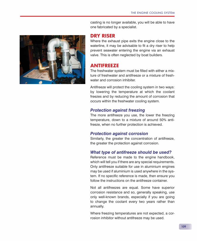
THE ENGINE COOLING SYSTEM
109
casting is no longer available, you will be able to have one fabricated by a specialist.
DRY RISERWhere the exhaust pipe exits the engine close to the waterline, it may be advisable to fi t a dry riser to help prevent seawater entering the engine via an exhaust valve. This is often neglected by boat builders.
ANTIFREEZEThe freshwater system must be fi lled with either a mix-ture of freshwater and antifreeze or a mixture of fresh-water and corrosion inhibiter.
Antifreeze will protect the cooling system in two ways: by lowering the temperature at which the coolant freezes and by reducing the amount of corrosion that occurs within the freshwater cooling system.
Protection against freezingThe more antifreeze you use, the lower the freezing temperature, down to a mixture of around 50% anti-freeze, when no further protection is achieved.
Protection against corrosionSimilarly, the greater the concentration of antifreeze, the greater the protection against corrosion.
What type of antifreeze should be used?Reference must be made to the engine handbook, which will tell you if there are any special requirements. Only antifreeze suitable for use in aluminium engines may be used if aluminium is used anywhere in the sys-tem. If no specifi c reference is made, then ensure you follow the instructions on the antifreeze container.
Not all antifreezes are equal. Some have superior corrosion resistance and so, generally speaking, use only well-known brands, especially if you are going to change the coolant every two years rather than annually.
Where freezing temperatures are not expected, a cor-rosion inhibitor without antifreeze may be used.
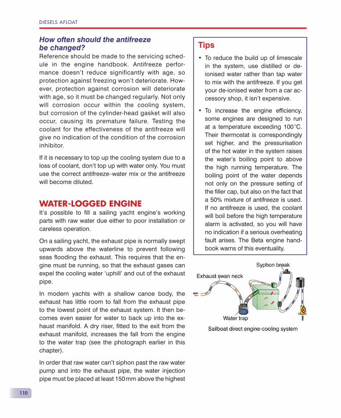
DIESELS AFLOAT
110
How often should the antifreezebe changed?Reference should be made to the servicing sched-ule in the engine handbook. Antifreeze perfor-mance doesn’t reduce significantly with age, so protection against freezing won’t deteriorate. How-ever, protection against corrosion will deteriorate with age, so it must be changed regularly. Not only will corrosion occur within the cooling system, but corrosion of the cylinder-head gasket will also occur, causing its premature failure. Testing the coolant for the effectiveness of the antifreeze will give no indication of the condition of the corrosioninhibitor.
If it is necessary to top up the cooling system due to a loss of coolant, don’t top up with water only. You must use the correct antifreeze—water mix or the antifreeze will become diluted.
WATER-LOGGED ENGINEIt’s possible to fi ll a sailing yacht engine’s working parts with raw water due either to poor installation or careless operation.
On a sailing yacht, the exhaust pipe is normally swept upwards above the waterline to prevent following seas fl ooding the exhaust. This requires that the en-gine must be running, so that the exhaust gases can expel the cooling water ‘uphill’ and out of the exhaust pipe.
In modern yachts with a shallow canoe body, the exhaust has little room to fall from the exhaust pipe to the lowest point of the exhaust system. It then be-comes even easier for water to back up into the ex-haust manifold. A dry riser, fi tted to the exit from the exhaust manifold, increases the fall from the engine to the water trap (see the photograph earlier in this chapter).
In order that raw water can’t siphon past the raw water pump and into the exhaust pipe, the water injection pipe must be placed at least 150 mm above the highest
Tips
To reduce the build up of limescale in the system, use distilled or de-ionised water rather than tap water to mix with the antifreeze. If you get your de-ionised water from a car ac-cessory shop, it isn’t expensive.
To increase the engine effi ciency, some engines are designed to run at a temperature exceeding 100 �C. Their thermostat is correspondingly set higher, and the pressurisation of the hot water in the system raises the water’s boiling point to above the high running temperature. The boiling point of the water depends not only on the pressure setting of the fi ller cap, but also on the fact that a 50% mixture of antifreeze is used. If no antifreeze is used, the coolant will boil before the high temperature alarm is activated, so you will have no indication if a serious overheating fault arises. The Beta engine hand-book warns of this eventuality.
•
•
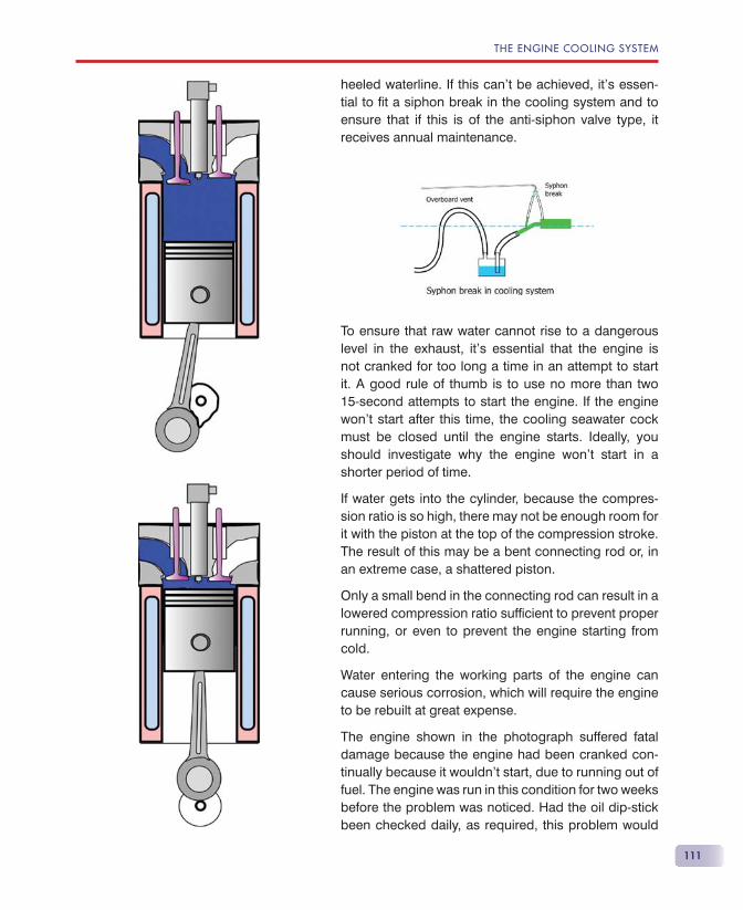
THE ENGINE COOLING SYSTEM
111
heeled waterline. If this can’t be achieved, it’s essen-tial to fi t a siphon break in the cooling system and to ensure that if this is of the anti-siphon valve type, it receives annual maintenance.
To ensure that raw water cannot rise to a dangerous level in the exhaust, it’s essential that the engine is not cranked for too long a time in an attempt to start it. A good rule of thumb is to use no more than two 15-second attempts to start the engine. If the engine won’t start after this time, the cooling seawater cock must be closed until the engine starts. Ideally, you should investigate why the engine won’t start in a shorter period of time.
If water gets into the cylinder, because the compres-sion ratio is so high, there may not be enough room for it with the piston at the top of the compression stroke. The result of this may be a bent connecting rod or, in an extreme case, a shattered piston.
Only a small bend in the connecting rod can result in a lowered compression ratio suffi cient to prevent proper running, or even to prevent the engine starting from cold.
Water entering the working parts of the engine can cause serious corrosion, which will require the engine to be rebuilt at great expense.
The engine shown in the photograph suffered fatal damage because the engine had been cranked con-tinually because it wouldn’t start, due to running out of fuel. The engine was run in this condition for two weeks before the problem was noticed. Had the oil dip-stick been checked daily, as required, this problem would
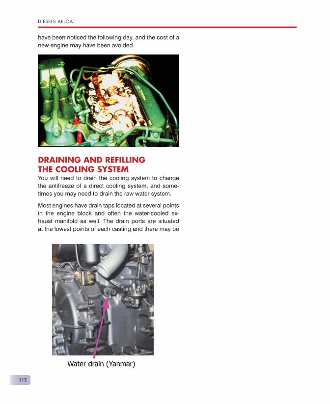
DIESELS AFLOAT
112
have been noticed the following day, and the cost of a new engine may have been avoided.
DRAINING AND REFILLING THE COOLING SYSTEMYou will need to drain the cooling system to change the antifreeze of a direct cooling system, and some-times you may need to drain the raw water system.
Most engines have drain taps located at several points in the engine block and often the water-cooled ex-haust manifold as well. The drain ports are situated at the lowest points of each casting and there may be
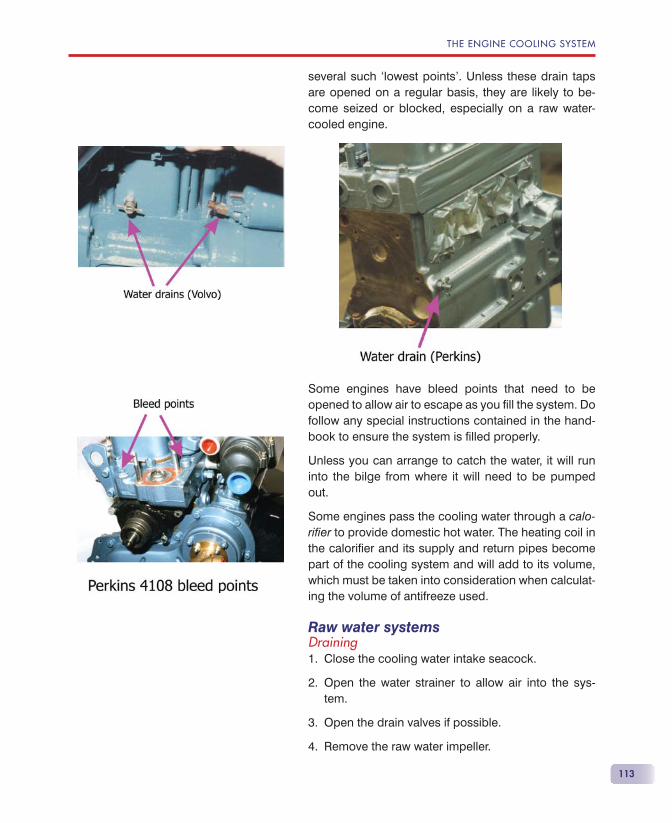
THE ENGINE COOLING SYSTEM
113
several such ‘lowest points’. Unless these drain taps are opened on a regular basis, they are likely to be-come seized or blocked, especially on a raw water-cooled engine.
Some engines have bleed points that need to be opened to allow air to escape as you fi ll the system. Do follow any special instructions contained in the hand-book to ensure the system is fi lled properly.
Unless you can arrange to catch the water, it will run into the bilge from where it will need to be pumped out.
Some engines pass the cooling water through a calo-rifi er to provide domestic hot water. The heating coil in the calorifi er and its supply and return pipes become part of the cooling system and will add to its volume, which must be taken into consideration when calculat-ing the volume of antifreeze used.
Raw water systemsDraining
Close the cooling water intake seacock.
Open the water strainer to allow air into the sys-tem.
Open the drain valves if possible.
Remove the raw water impeller.
1.
2.
3.
4.
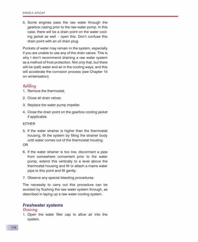
DIESELS AFLOAT
114
Some engines pass the raw water through the gearbox casing prior to the raw water pump. In this case, there will be a drain point on the water cool-ing jacket as well — open this. Don’t confuse this drain point with an oil drain plug.
Pockets of water may remain in the system, especially if you are unable to use any of the drain valves. This is why I don’t recommend draining a raw water system as a method of frost protection. Not only that, but there will be (salt) water and air in the cooling ways, and this will accelerate the corrosion process (see Chapter 15 on winterisation).
Refi llingRemove the thermostat.
Close all drain valves.
Replace the water pump impeller.
Close the drain point on the gearbox cooling jacket if applicable.
EITHER
If the water strainer is higher than the thermostat housing, fi ll the system by fi lling the strainer body until water comes out of the thermostat housing.
OR
If the water strainer is too low, disconnect a pipe from somewhere convenient prior to the water pump, extend this vertically to a level above the thermostat housing and fi ll or attach a mains water pipe to this point and fi ll gently.
Observe any special bleeding procedures.
The necessity to carry out this procedure can be avoided by fl ushing the raw water system through, as described in laying up a raw water cooling system.
Freshwater systemsDraining
Open the water fi ller cap to allow air into the system.
5.
1.
2.
3.
4.
5.
6.
7.
1.
THE ENGINE COOLING SYSTEM
115
Open the drain valves. If they won’t open, then the system cannot be drained fully.
Disconnect a freshwater hose as low down in the system as possible to speed up the draining process.
Refi llingClose all drain valves.
Reconnect any disconnected pipes.
Fill the system slowly through the fi ller cap. When the system seems to be full, allow time for water to fl ow into remote parts of the system and continue fi lling until it will accept no more.
Observe any special bleeding procedures.
2.
3.
1.
2.
3.
4.

117
Lubricating oil is contained in the engine oil sump located at the bottom of the engine. This is the equivalent of the oil ‘tank’. An engine-driven oil
pump sucks oil from the sump via a coarse strainer, immersed in the sump. The oil, under pressure, is delivered to the oil fi lter, after which it is distributed by means of pipes and oil galleries to all the parts of the engine requiring lubrication. The oil returns to the sump by dribbling back down the sides and working parts of the engine. Once the engine is stopped, it takes some time for all the oil to return to the sump.
THE SUMP (OIL PAN)The sump is the lowest part of the engine. On sailing boats it often needs to be deeper than its standard ‘automotive’ cousin to ensure that the strainer stays immersed in oil even when the boat is heeled. The engine handbook normally states the maximum heel allowed when the engine is running. Commonly it is between 25 and 30 degrees.
The walls of the sump allow heat to be extracted from the hot oil by air passing around it, so it’s essential to allow free circulation of air around the sump.
Unlike a car, there’s normally insuffi cient room below the engine to allow old oil to be drained into a container.
Lubrication
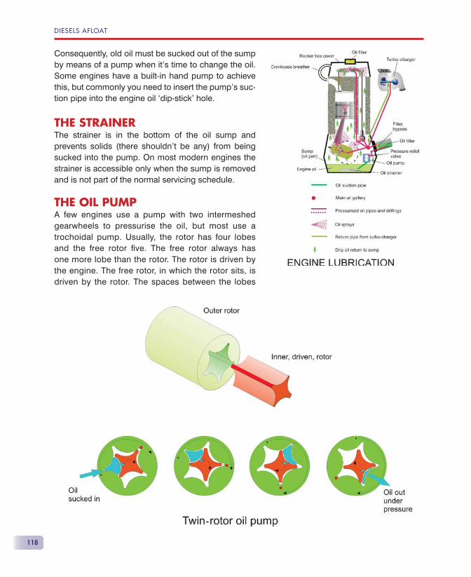
DIESELS AFLOAT
118
Consequently, old oil must be sucked out of the sump by means of a pump when it’s time to change the oil. Some engines have a built-in hand pump to achieve this, but commonly you need to insert the pump’s suc-tion pipe into the engine oil ‘dip-stick’ hole.
THE STRAINERThe strainer is in the bottom of the oil sump and prevents solids (there shouldn’t be any) from being sucked into the pump. On most modern engines the strainer is accessible only when the sump is removed and is not part of the normal servicing schedule.
THE OIL PUMPA few engines use a pump with two intermeshed gearwheels to pressurise the oil, but most use a trochoidal pump. Usually, the rotor has four lobes and the free rotor fi ve. The free rotor always has one more lobe than the rotor. The rotor is driven by the engine. The free rotor, in which the rotor sits, is driven by the rotor. The spaces between the lobes
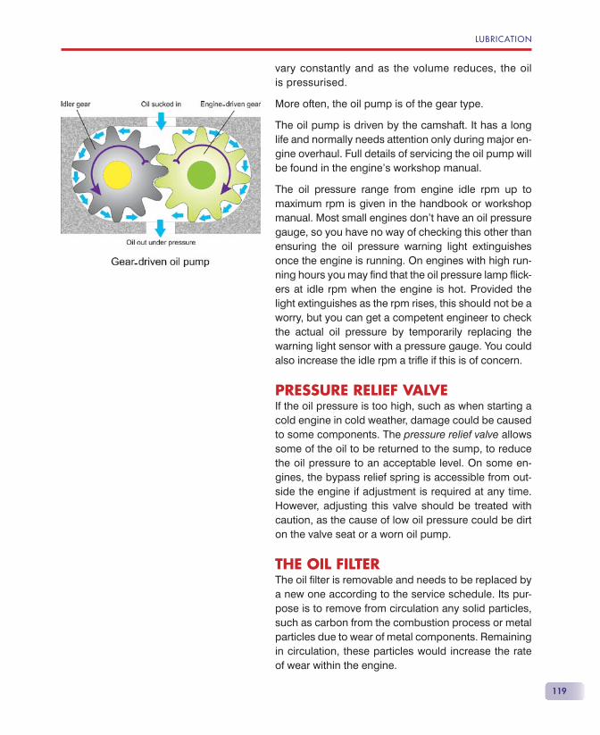
119
vary constantly and as the volume reduces, the oil is pressurised.
More often, the oil pump is of the gear type.
The oil pump is driven by the camshaft. It has a long life and normally needs attention only during major en-gine overhaul. Full details of servicing the oil pump will be found in the engine’s workshop manual.
The oil pressure range from engine idle rpm up to maximum rpm is given in the handbook or workshop manual. Most small engines don’t have an oil pressure gauge, so you have no way of checking this other than ensuring the oil pressure warning light extinguishes once the engine is running. On engines with high run-ning hours you may fi nd that the oil pressure lamp fl ick-ers at idle rpm when the engine is hot. Provided the light extinguishes as the rpm rises, this should not be a worry, but you can get a competent engineer to check the actual oil pressure by temporarily replacing the warning light sensor with a pressure gauge. You could also increase the idle rpm a trifl e if this is of concern.
PRESSURE RELIEF VALVEIf the oil pressure is too high, such as when starting a cold engine in cold weather, damage could be caused to some components. The pressure relief valve allows some of the oil to be returned to the sump, to reduce the oil pressure to an acceptable level. On some en-gines, the bypass relief spring is accessible from out-side the engine if adjustment is required at any time. However, adjusting this valve should be treated with caution, as the cause of low oil pressure could be dirt on the valve seat or a worn oil pump.
THE OIL FILTERThe oil fi lter is removable and needs to be replaced by a new one according to the service schedule. Its pur-pose is to remove from circulation any solid particles, such as carbon from the combustion process or metal particles due to wear of metal components. Remaining in circulation, these particles would increase the rate of wear within the engine.
LUBRICATION
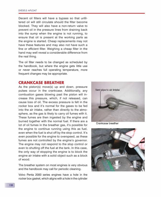
DIESELS AFLOAT
120
Decent oil fi lters will have a bypass so that unfi l-tered oil will still circulate should the fi lter become blocked. They will also have a non-return valve to prevent oil in the pressure lines from draining back into the sump when the engine is not running, to ensure that oil is present at the working parts as the engine is started. Cheap replacements may not have these features and may also not have such a fi ne or effi cient fi lter. Weighing a cheap fi lter in the hand may well reveal a considerable difference from the real thing.
The oil fi lter needs to be changed as scheduled by the handbook, but where the engine gets little use or never reaches full operating temperature, more frequent changes may be appropriate.
CRANKCASE BREATHERAs the piston(s) move(s) up and down, pressure pulses occur in the crankcase. Additionally, any combustion gases blowing past the piston will in-crease this pressure, which, if not released, can cause loss of oil. The excess pressure is felt in the rocker box and it’s normal for the gases to be fed into the air intake, rather than directly to the atmo-sphere, as the gas is likely to carry oil fumes with it. These fumes are then ingested by the engine and burned together with the normal fuel. If there are a lot of oil fumes in the breather gas, it’s possible for the engine to continue running using this as fuel, even when the fuel is shut off by the stop control. It’s even possible for the engine to overspeed, as these fumes are not controlled by the engine’s governor. The engine may not respond to the stop control or even to shutting off the fuel at the tank. In this case, the only way of stopping the engine is to block the engine air intake with a solid object such as a block of wood.
The breather system on most engines is very obvious and the handbook may call for periodic cleaning.
Volvo Penta 2000 series engines have a hole in the rocker box gasket, which aligns with a hole in the cylinder
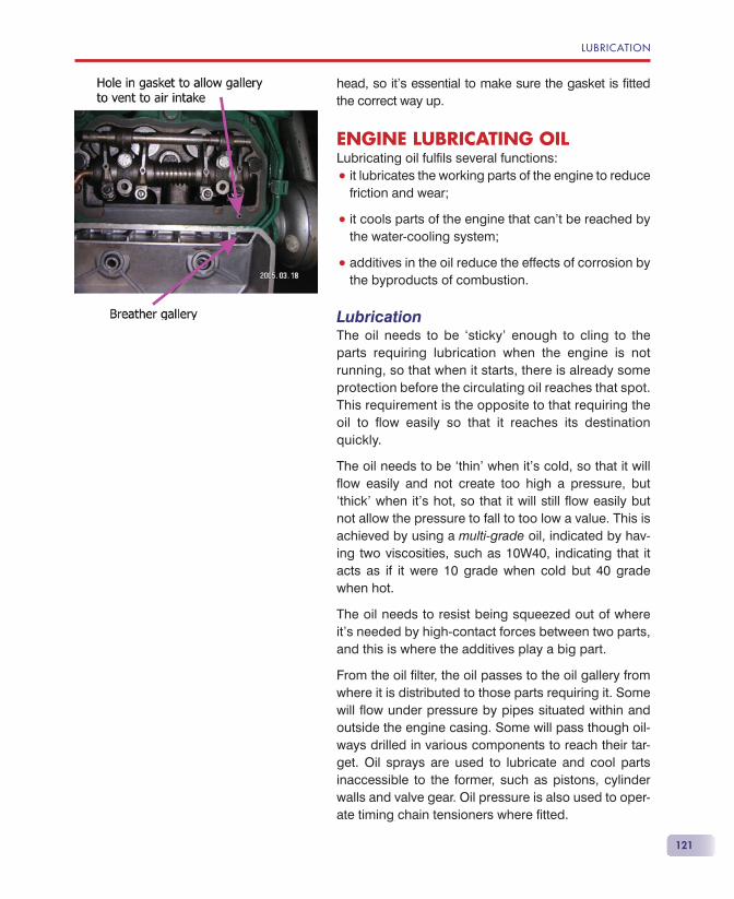
121
head, so it’s essential to make sure the gasket is fi tted the correct way up.
ENGINE LUBRICATING OILLubricating oil fulfi ls several functions:
• it lubricates the working parts of the engine to reduce friction and wear;
• it cools parts of the engine that can’t be reached by the water-cooling system;
• additives in the oil reduce the effects of corrosion by the byproducts of combustion.
LubricationThe oil needs to be ‘sticky’ enough to cling to the parts requiring lubrication when the engine is not running, so that when it starts, there is already some protection before the circulating oil reaches that spot. This requirement is the opposite to that requiring the oil to fl ow easily so that it reaches its destination quickly.
The oil needs to be ‘thin’ when it’s cold, so that it will fl ow easily and not create too high a pressure, but ‘thick’ when it’s hot, so that it will still fl ow easily but not allow the pressure to fall to too low a value. This is achieved by using a multi-grade oil, indicated by hav-ing two viscosities, such as 10W40, indicating that it acts as if it were 10 grade when cold but 40 grade when hot.
The oil needs to resist being squeezed out of where it’s needed by high-contact forces between two parts, and this is where the additives play a big part.
From the oil fi lter, the oil passes to the oil gallery from where it is distributed to those parts requiring it. Some will fl ow under pressure by pipes situated within and outside the engine casing. Some will pass though oil-ways drilled in various components to reach their tar-get. Oil sprays are used to lubricate and cool parts inaccessible to the former, such as pistons, cylinder walls and valve gear. Oil pressure is also used to oper-ate timing chain tensioners where fi tted.
LUBRICATION

DIESELS AFLOAT
122
CoolingWhere components need to be cooled, oil is sprayed onto surfaces, such as the inside of the hollow pis-ton, to take away the heat of combustion. As com-bustion temperatures can be close to 1000 �C, the inside of the piston gets very hot and so does the cylinder wall, so the oil must not lose its lubricating properties under these conditions. The conditions are even more severe when it comes to cooling a turbo-charger.
CorrosionOne of the byproducts of combustion is sulphurous acid. At normal engine running temperatures this is volatile and most of it will ‘boil off’ before contaminating the lubricating oil. If the sulphurous acid doesn’t reach suffi cient temperature, or cools, it becomes sulphuric acid and will then contaminate the oil, leading to signifi cant corrosion within the engine.
Good diesel engine lubricating oil will have corrosion inhibitors incorporated. These inhibitors will be used up in doing their job, and the cooler the engine is run, the more quickly they will be exhausted. Light, or infrequent, engine use will require the oil to be changed more frequently than specifi ed in the handbook.
The oil specifi cationDiesel engine lubricating oil is normally listed under the API (American Petroleum Industry) system in the form of API xx-yWzz.
• xx indicates the specifi cation, especially of the additives, according to the type of engine and use. Grade CC is for normally aspirated, light-duty engines and CF is for hard-worked turbo-charged engines. It doesn’t benefi t the engine to use a higher grade than specifi ed.
• yWzz indicates the viscosity of a multi-grade oil, such as 10W40. This is chosen according to the ambient temperature of the air where the engine will be used. There is often a temperature table in the engine handbook indicating the viscosity you should use.
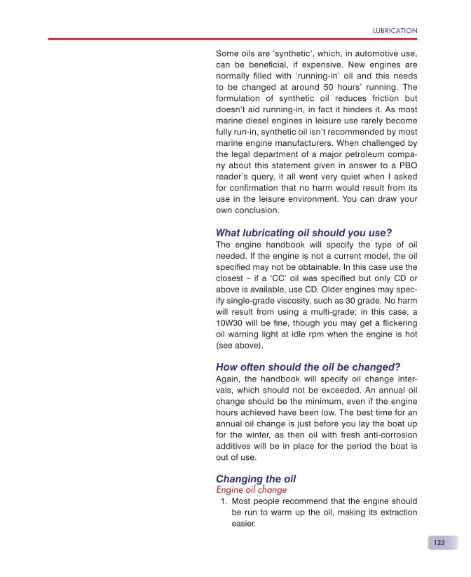
123
Some oils are ‘synthetic’, which, in automotive use, can be benefi cial, if expensive. New engines are normally fi lled with ‘running-in’ oil and this needs to be changed at around 50 hours’ running. The formulation of synthetic oil reduces friction but doesn’t aid running-in, in fact it hinders it. As most marine diesel engines in leisure use rarely become fully run-in, synthetic oil isn’t recommended by most marine engine manufacturers. When challenged by the legal department of a major petroleum compa-ny about this statement given in answer to a PBO reader’s query, it all went very quiet when I asked for confi rmation that no harm would result from its use in the leisure environment. You can draw your own conclusion.
What lubricating oil should you use?The engine handbook will specify the type of oil needed. If the engine is not a current model, the oil specifi ed may not be obtainable. In this case use the closest — if a ‘CC’ oil was specifi ed but only CD or above is available, use CD. Older engines may spec-ify single-grade viscosity, such as 30 grade. No harm will result from using a multi-grade; in this case, a 10W30 will be fi ne, though you may get a fl ickering oil warning light at idle rpm when the engine is hot (see above).
How often should the oil be changed?Again, the handbook will specify oil change inter-vals, which should not be exceeded. An annual oil change should be the minimum, even if the engine hours achieved have been low. The best time for an annual oil change is just before you lay the boat up for the winter, as then oil with fresh anti-corrosion additives will be in place for the period the boat is out of use.
Changing the oilEngine oil change
1. Most people recommend that the engine should be run to warm up the oil, making its extraction easier.
LUBRICATION
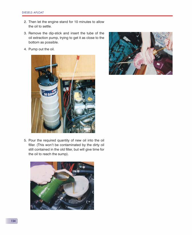
DIESELS AFLOAT
124
2. Then let the engine stand for 10 minutes to allow the oil to settle.
3. Remove the dip-stick and insert the tube of the oil extraction pump, trying to get it as close to the bottom as possible.
4. Pump out the oil.
5. Pour the required quantity of new oil into the oil fi ller. (This won’t be contaminated by the dirty oil still contained in the old fi lter, but will give time for the oil to reach the sump).
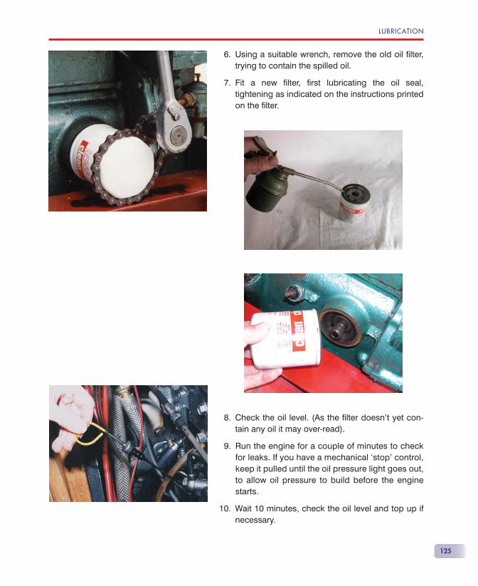
125
6. Using a suitable wrench, remove the old oil fi lter, trying to contain the spilled oil.
7. Fit a new fi lter, fi rst lubricating the oil seal, tightening as indicated on the instructions printed on the fi lter.
8. Check the oil level. (As the fi lter doesn’t yet con-tain any oil it may over-read).
9. Run the engine for a couple of minutes to check for leaks. If you have a mechanical ‘stop’ control, keep it pulled until the oil pressure light goes out, to allow oil pressure to build before the engine starts.
10. Wait 10 minutes, check the oil level and top up if necessary.
LUBRICATION
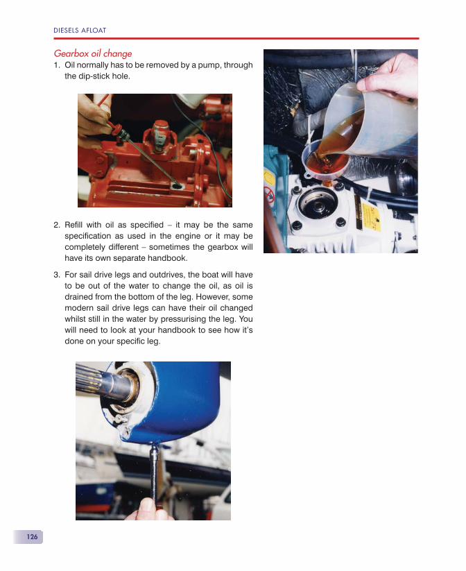
DIESELS AFLOAT
126
Gearbox oil changeOil normally has to be removed by a pump, through the dip-stick hole.
Refi ll with oil as specifi ed — it may be the same specifi cation as used in the engine or it may be completely different — sometimes the gearbox will have its own separate handbook.
For sail drive legs and outdrives, the boat will have to be out of the water to change the oil, as oil is drained from the bottom of the leg. However, some modern sail drive legs can have their oil changed whilst still in the water by pressurising the leg. You will need to look at your handbook to see how it’s done on your specifi c leg.
1.
2.
3.

127
The air system is deceptively simple, but any defects can have large repercussions. It com-prises:
• the air entering the engine compartment;
• the air supply via the air intake;
• the exhaust system.
In effect the diesel engine is a large and efficient air pump and is capable of a large suction at the air intake. A 30 hp diesel engine running at 3000 rpm will consume around 1000 litres of air per min-ute, even when it is developing little power. That’s a box of air 1 metre � 1 metre � 1 metre every minute.
Many boat builders install a 10 cm diameter pipe to supply air to the engine compartment, and the engine will suck through this pipe air at a velocity of around 4 metres per second without any help from the small fan that some boat builders seem to fi t. Other boat build-ers supply no dedicated air supply with no detrimental
The Air System
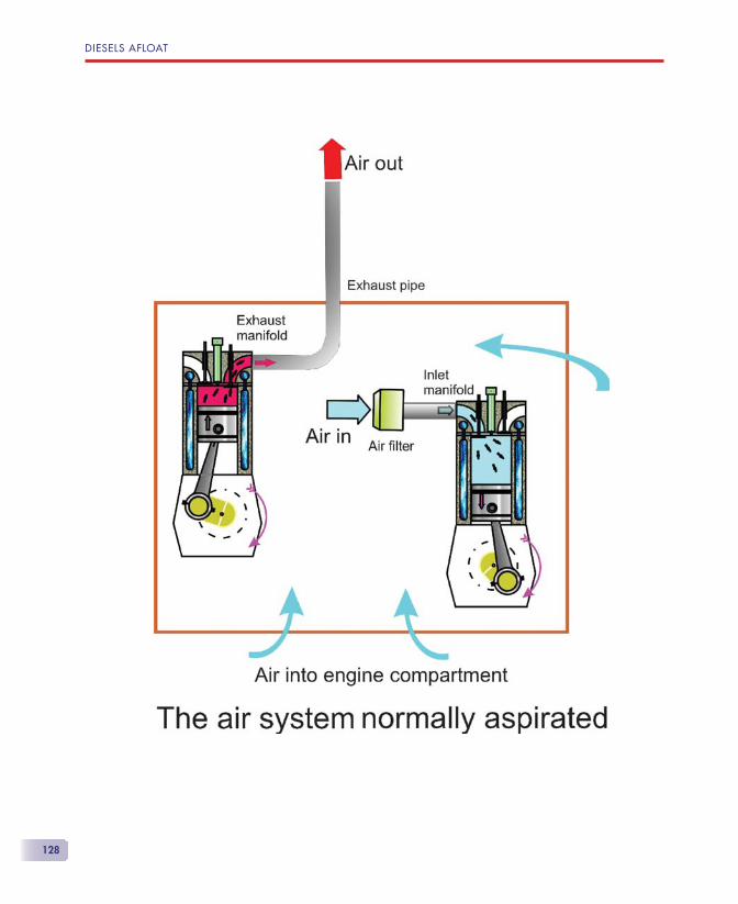
DIESELS AFLOAT
128
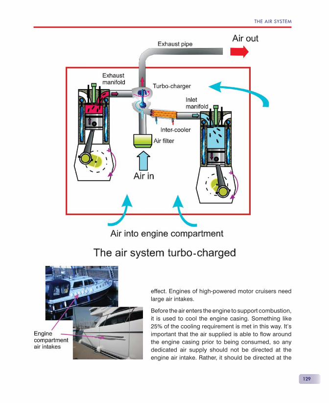
129
effect. Engines of high-powered motor cruisers need large air intakes.
Before the air enters the engine to support combustion, it is used to cool the engine casing. Something like 25% of the cooling requirement is met in this way. It’s important that the air supplied is able to fl ow around the engine casing prior to being consumed, so any dedicated air supply should not be directed at the engine air intake. Rather, it should be directed at the
THE AIR SYSTEM
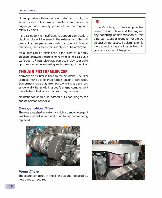
DIESELS AFLOAT
130
oil sump. Where there’s no dedicated air supply, the air is sucked in from many directions and cools the engine just as effi ciently, provided that the engine is relatively small.
If the air supply is insuffi cient to support combustion, black smoke will be seen in the exhaust and this will cease if an engine access hatch is opened. Should this occur, then a better air supply must be arranged.
Air supply can be diminished if the exhaust is partly blocked, because if there’s no room to let the air out, it can’t get in. Partial blockage can occur due to a build up of soot or to delaminating and softening of the pipe.
THE AIR FILTER/SILENCERNormally an air fi lter is fi tted to the air intake. The fi lter element may be of sponge rubber, paper or wire wool. Sometimes there’s only an empty box acting as a silencer, as generally the air within a boat’s engine compartment is not laden with dust and dirt, as it may be on land.
Maintenance should be carried out according to the engine service schedule.
Sponge rubber fi ltersThese are washed in water to which a gentle detergent has been added, rinsed and hung to dry before being replaced.
Paper fi ltersThese are contained in the fi lter box and replaced by new ones as required.
Tip
If there’s a length of rubber pipe be-tween the air intake and the engine, any softening or delamination of this pipe can cause a reduction of airfl ow as suction increases. If delamination is the cause, this may not be visible until you remove the rubber pipe.
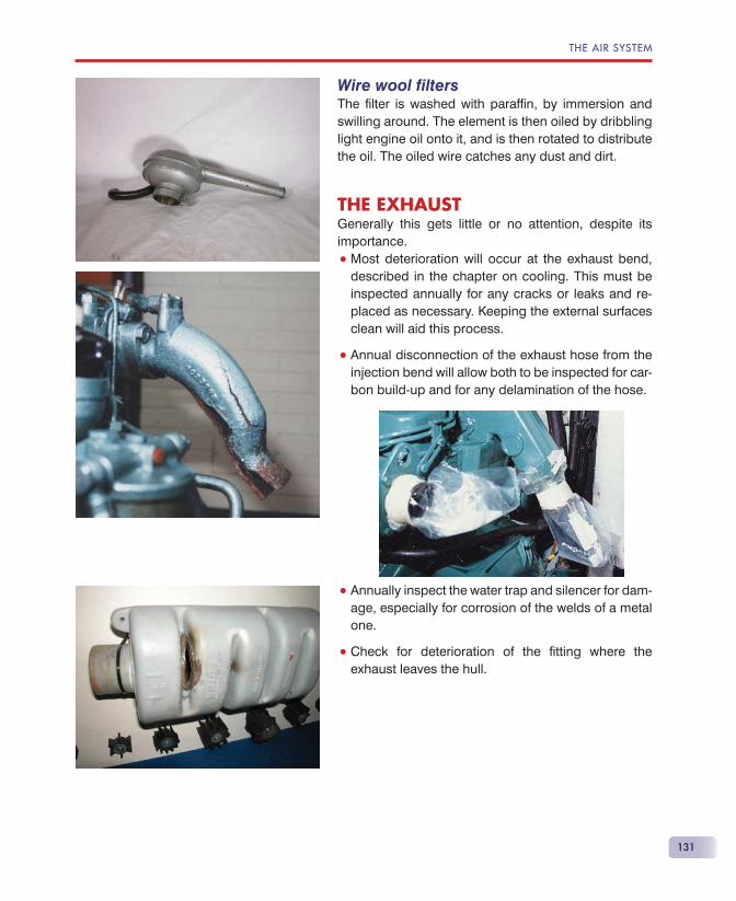
131
Wire wool fi ltersThe fi lter is washed with paraffi n, by immersion and swilling around. The element is then oiled by dribbling light engine oil onto it, and is then rotated to distribute the oil. The oiled wire catches any dust and dirt.
THE EXHAUSTGenerally this gets little or no attention, despite its importance.
• Most deterioration will occur at the exhaust bend, described in the chapter on cooling. This must be inspected annually for any cracks or leaks and re-placed as necessary. Keeping the external surfaces clean will aid this process.
• Annual disconnection of the exhaust hose from the injection bend will allow both to be inspected for car-bon build-up and for any delamination of the hose.
• Annually inspect the water trap and silencer for dam-age, especially for corrosion of the welds of a metal one.
• Check for deterioration of the fi tting where the exhaust leaves the hull.
THE AIR SYSTEM

133
If we remember that a basic marine diesel engine requires no electricity to run, then the electrical system to support the engine should be very sim-
ple. A simple ‘hand start’ diesel needs no electricity at all.
Few boats today have no ancillary electrical compo-nents, such as cabin and navigation lights, electronic navigation equipment, etc., so the basic engine elec-trical system takes these requirements partially into account. However, it’s unlikely to support extended cruising or the fi tting of ‘lifestyle’ equipment, such as a TV, microwave oven, etc.
Basically, the engine electrical system is straight-forward and easy to understand if you have a block diagram, which you can use in conjunction with the engine’s normal wiring diagram.
TYPICAL ENGINE ELECTRICS BLOCK DIAGRAMSThe start circuit diagram allows you to visualise how the parts of the system are joined electrically. You can use the engine block diagram in conjunction with your own engine wiring diagram to get the colour of the wires. If you copy this diagram and cross out the bits
Engine Electrics
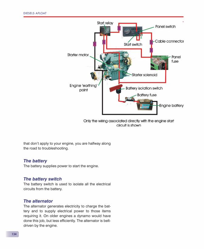
DIESELS AFLOAT
134
that don’t apply to your engine, you are halfway along the road to troubleshooting.
The batteryThe battery supplies power to start the engine.
The battery switchThe battery switch is used to isolate all the electrical circuits from the battery.
The alternatorThe alternator generates electricity to charge the bat-tery and to supply electrical power to those items requiring it. On older engines a dynamo would have done this job, but less effi ciently. The alternator is belt-driven by the engine.
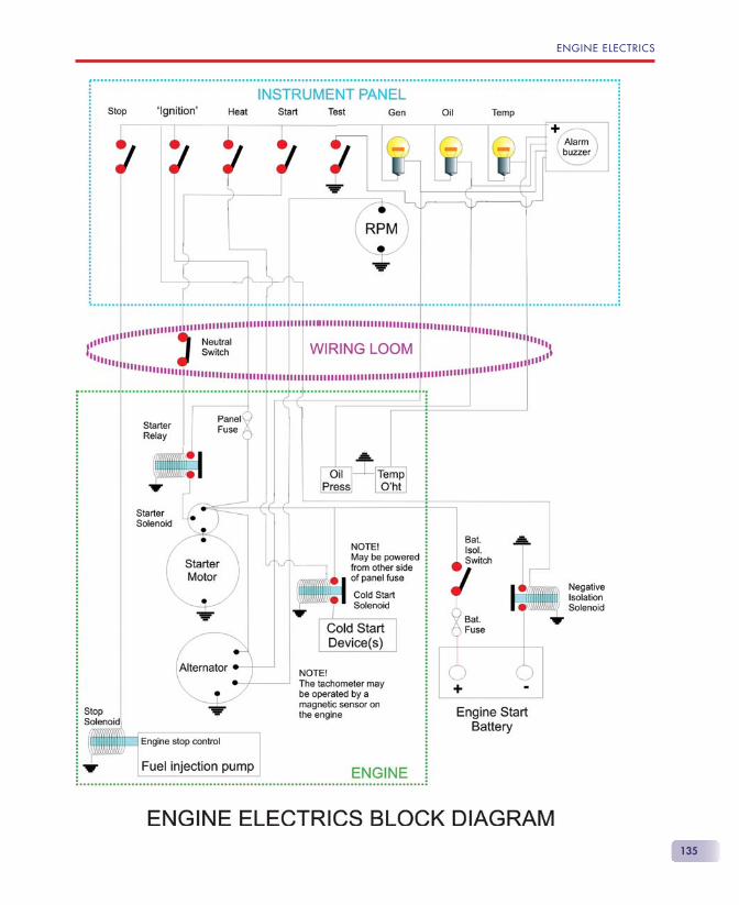
ENGINE ELECTRICS
135
DIESELS AFLOAT
136
The starter motorThe starter motor is an electric motor powered from the battery and is used to start the engine.
The starter solenoidThe current required to start the engine is very high. If this current had to pass through the starter switch, the cabling and the switch itself would need to be very heavy duty, and hence expensive and unwieldy. The solenoid allows a low-current circuit to operate the solenoid’s electromagnetic coil and contacts, which, in turn, then allow the high starting current to fl ow. On modern engines, the solenoid also activates the starter pinion clutch.
The starter relayIf the circuit between the starter switch and the starter solenoid is too long, high resistance may make the starter operation unreliable. In this case an intermedi-ate electromagnetic relay may be used to boost the current to the starter solenoid.
The cold start relayIf cold start devices, such as heater plugs, are used, these will be activated using a relay to handle their operating current. This is usually operated by holding the start key at the ‘heat’ position for the time specifi ed before con-tinuing with the engine start, or by pressing a ‘heat’ but-ton. On engines with full electronic engine management systems, this is activated automatically as required.
The stop solenoidOn some engines the lever used to cut off the fuel sup-ply at the fuel injection pump to stop the engine is op-erated by an electromagnetic stop solenoid rather than by pulling a stop handle. It is operated by holding the start key at the ‘stop’ position or by using the ‘stop’ but-ton until the engine stops. In an automotive application the stop solenoid is powered to run. This means that if you lose electrical power, the engine will stop. In most marine applications the stop solenoid is powered to stop and requires no power for the engine to continue running. Engines used to power a generator (gen. set.) are run unsupervised, so any fault detected is required
ENGINE ELECTRICS
137
to shut down the engine automatically. In this case the stop solenoid is powered to run and any fault detected just switches off the power and stops the engine.
The ‘negative’ isolation solenoidSteel and aluminium hulls can suffer from electrolytic corrosion. Ideally, the engine electrics should use a two-wire system, where all negative wires are actual cables, rather than using the engine block itself as the negative ‘wire’. This requires special and expen-sive items such as the starter motor, and so is not al-ways used. For economic reasons these installations often use normal single-wire components. To help minimise corrosion where normal single-wire com-ponents are used, a relay is sometimes introduced into the negative cable between the battery negative terminal and the engine block. This solenoid is acti-vated by the engine start switch so that the negative circuit is activated only when the engine is running.
The ‘ignition’ switchAs a diesel has no ‘ignition’ circuit, the term ‘ignition switch’ is a misnomer, but it’s understood by all. This switch is often multifunctional and in its ‘RUN’ position, the instrument panel is energised. Other positions may include ‘HEAT’, ‘START’ and ‘STOP’, or there may be separate switches for these functions.
The engine ‘fuse’Most engines have a fuse or circuit-breaker in the supply (�ve) wire to the engine panel. This protects all the engine circuits except the starter ‘power’ circuit. This fuse isn’t always mentioned in the handbook (Yanmar), though its failure will render the engine ‘dead’.
The battery fuseThis is rarely fi tted by boat builders. Its omission could lead to an electrical fi re if the supply from the battery to the engine suffers a short circuit. An argument for not fi tting one is that its failure with the engine running will result in the alternator’s diodes being destroyed. Personally, I would prefer that to the boat being destroyed by fi re!
Tips
The negative isolation solenoid will not appear on the engine electrical wiring diagram as it’s part of the ‘boat’ and the owner may be com-pletely unaware of its presence. In the case of the engine failing to start, this may be the culprit.
Solenoids which spend a long time energised have two sets of contacts to supply the power. The fi rst set oper-ates the action of the solenoid, which takes quite a bit of current, and once the contact is made, another set of contacts is energised to ‘hold’ the solenoid engaged, which takes far less current. The operating current is then switched off automatically. When setting up or troubleshooting this type of solenoid, it’s necessary to check both sets of contacts for correct operation.
•
•

DIESELS AFLOAT
138
The tachometerThis instrument indicates the engine rpm. It may be driven in one of two ways:
• From special connections on the back of the alternator, in which case belt slip or a change of alternator pulley size will give incorrect read-ings. Generally it doesn’t matter what make of tachometer you use, as long as it’s set up for the pulley ratio.
• From a dedicated transducer situated within the engine. These generally count magnetic pulses and you need the correct proprietary tacho.
Although a tachometer is a very good troubleshoot-ing aid, one is often not fi tted because of the extra cost.
Warning lightsSensors on the engine detect low oil pressure, high coolant temperature and no output from the alterna-tor (dynamo). These cause their respective warning lights to illuminate when a fault occurs. If you’re lucky, there may also be an indication of cooling water fl ow.
When the ‘ignition switch’ is turned ‘ON’:
• The oil low pressure warning light should illuminate as there’s no oil pressure.
• As there’s no alternator output, its warning light should illuminate as well.
• As the coolant temperature is not too high, this warning light will not illuminate, so there should be a ‘TEST’ switch to check that this light is working.
• Yanmar sail drive engines also have a warning light to indicate that there’s water between the internal and external sail drive leg-sealing diaphragms. This should not illuminate when the ‘ignition’ is turned ‘ON’, so the ‘TEST’ switch will test this as well.
• If cold start heater plugs are installed, an indicator light will illuminate when you select ‘HEAT’. This is not tested with the ‘TEST’ switch.
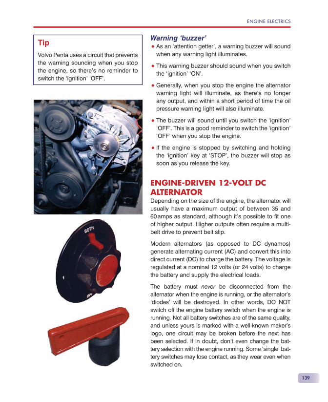
ENGINE ELECTRICS
139
Warning ‘buzzer’• As an ‘attention getter’, a warning buzzer will sound
when any warning light illuminates.
• This warning buzzer should sound when you switch the ‘ignition’ ‘ON’.
• Generally, when you stop the engine the alternator warning light will illuminate, as there’s no longer any output, and within a short period of time the oil pressure warning light will also illuminate.
• The buzzer will sound until you switch the ‘ignition’ ‘OFF’. This is a good reminder to switch the ‘ignition’ ‘OFF’ when you stop the engine.
• If the engine is stopped by switching and holding the ‘ignition’ key at ‘STOP’, the buzzer will stop as soon as you release the key.
ENGINE-DRIVEN 12-VOLT DC ALTERNATORDepending on the size of the engine, the alternator will usually have a maximum output of between 35 and 60 amps as standard, although it’s possible to fi t one of higher output. Higher outputs often require a multi-belt drive to prevent belt slip.
Modern alternators (as opposed to DC dynamos) generate alternating current (AC) and convert this into direct current (DC) to charge the battery. The voltage is regulated at a nominal 12 volts (or 24 volts) to charge the battery and supply the electrical loads.
The battery must never be disconnected from the alternator when the engine is running, or the alternator’s ‘diodes’ will be destroyed. In other words, DO NOT switch off the engine battery switch when the engine is running. Not all battery switches are of the same quality, and unless yours is marked with a well-known maker’s logo, one circuit may be broken before the next has been selected. If in doubt, don’t even change the bat-tery selection with the engine running. Some ‘single’ bat-tery switches may lose contact, as they wear even when switched on.
Tip
Volvo Penta uses a circuit that prevents the warning sounding when you stop the engine, so there’s no reminder to switch the ‘ignition’ ‘OFF’.
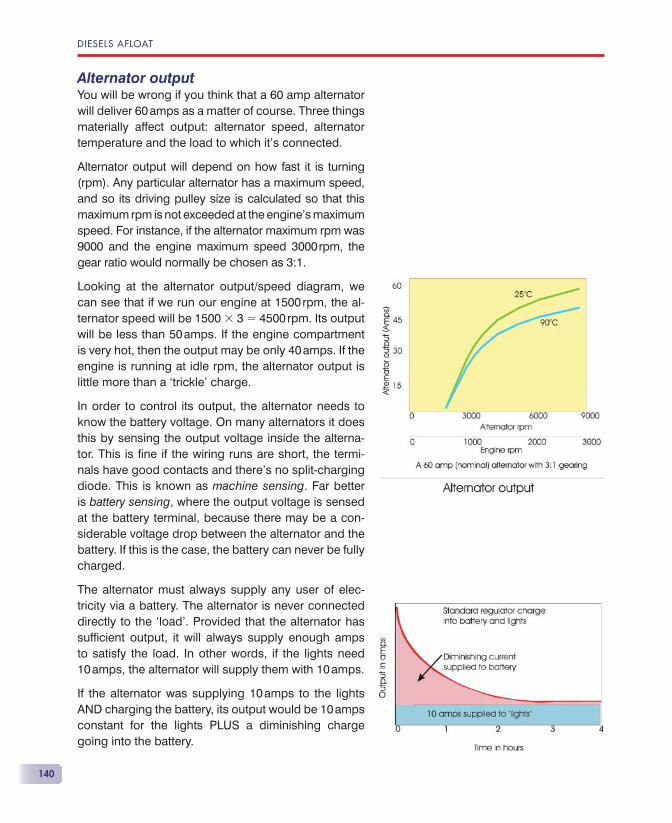
DIESELS AFLOAT
140
Alternator outputYou will be wrong if you think that a 60 amp alternator will deliver 60 amps as a matter of course. Three things materially affect output: alternator speed, alternator temperature and the load to which it’s connected.
Alternator output will depend on how fast it is turning (rpm). Any particular alternator has a maximum speed, and so its driving pulley size is calculated so that this maximum rpm is not exceeded at the engine’s maximum speed. For instance, if the alternator maximum rpm was 9000 and the engine maximum speed 3000 rpm, the gear ratio would normally be chosen as 3:1.
Looking at the alternator output/speed diagram, we can see that if we run our engine at 1500 rpm, the al-ternator speed will be 1500 � 3 � 4500 rpm. Its output will be less than 50 amps. If the engine compartment is very hot, then the output may be only 40 amps. If the engine is running at idle rpm, the alternator output is little more than a ‘trickle’ charge.
In order to control its output, the alternator needs to know the battery voltage. On many alternators it does this by sensing the output voltage inside the alterna-tor. This is fi ne if the wiring runs are short, the termi-nals have good contacts and there’s no split-charging diode. This is known as machine sensing. Far better is battery sensing, where the output voltage is sensed at the battery terminal, because there may be a con-siderable voltage drop between the alternator and the battery. If this is the case, the battery can never be fully charged.
The alternator must always supply any user of elec-tricity via a battery. The alternator is never connected directly to the ‘load’. Provided that the alternator has suffi cient output, it will always supply enough amps to satisfy the load. In other words, if the lights need 10 amps, the alternator will supply them with 10 amps.
If the alternator was supplying 10 amps to the lights AND charging the battery, its output would be 10 amps constant for the lights PLUS a diminishing charge going into the battery.
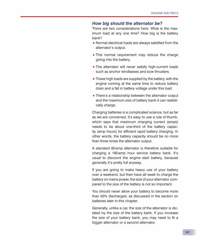
ENGINE ELECTRICS
141
How big should the alternator be?There are two considerations here: What is the max-imum load at any one time? How big is the battery bank?
• Normal electrical loads are always satisfi ed from the alternator’s output.
• This normal requirement may reduce the charge going into the battery.
• The alternator will never satisfy high-current loads such as anchor windlasses and bow thrusters.
• These high loads are supplied by the battery, with the engine running at the same time to reduce battery drain and a fall in battery voltage under this load.
• There’s a relationship between the alternator output and the maximum size of battery bank it can realisti-cally charge.
Charging batteries is a complicated science, but as far as we are concerned, it’s easy to use a rule of thumb, which says that maximum charging current (amps) needs to be about one-third of the battery capac-ity (amp hours) for effi cient rapid battery charging. In other words, the battery capacity should be no more than three times the alternator output.
A standard 60 amp alternator is therefore suitable for charging a 180 amp hour service battery bank. It’s usual to discount the engine start battery, because generally it’s pretty full anyway.
If you are going to make heavy use of your battery over a weekend, but then have all week to charge the battery on mains power, the size of your alternator com-pared to the size of the battery is not so important.
You should never allow your battery to become more than 50% discharged, as discussed in the section on batteries later in this chapter.
Generally, unlike a car, the size of the alternator is dic-tated by the size of the battery bank. If you increase the size of your battery bank, you may need to fi t a bigger alternator or a second alternator.
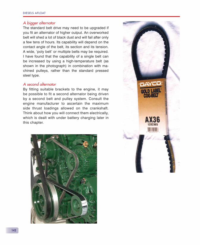
DIESELS AFLOAT
142
A bigger alternatorThe standard belt drive may need to be upgraded if you fi t an alternator of higher output. An overworked belt will shed a lot of black dust and will fail after only a few tens of hours. Its capability will depend on the contact angle of the belt, its section and its tension. A wide, ‘poly belt’ or multiple belts may be required. I have found that the capability of a single belt can be increased by using a high-temperature belt (as shown in the photograph) in combination with ma-chined pulleys, rather than the standard pressed steel type.
A second alternatorBy fitting suitable brackets to the engine, it may be possible to fit a second alternator being driven by a second belt and pulley system. Consult the engine manufacturer to ascertain the maximum side thrust loadings allowed on the crankshaft. Think about how you will connect them electrically, which is dealt with under battery charging later in this chapter.
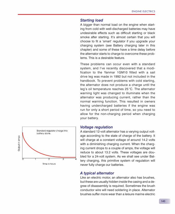
ENGINE ELECTRICS
143
Starting loadA bigger than normal load on the engine when start-ing from cold with well-discharged batteries may have undesirable effects such as diffi cult starting or black smoke after starting. It’s almost certain that you will choose to fi t a ‘smart’ regulator if you upgrade your charging system (see Battery charging later in this chapter) and some of these have a time delay before the alternator starts to charge to overcome these prob-lems. This is a desirable feature.
These problems can occur even with a standard system, and I’ve recently discovered that a modi-fication to the Yanmar 1GM10 fitted with a sail drive leg was made in 1992 but not included in the handbook. To prevent problems with cold starting, the alternator does not produce a charge until the leg’s oil temperature reaches 25 �C. The alternator warning light was changed to illuminate when the alternator was producing current, rather than the normal warning function. This resulted in owners having undercharged batteries if the engine was run for only a short period of time, so you need to allow for the non-charging period when charging your battery.
Voltage regulationA standard 12-volt alternator has a varying output volt-age according to the state of charge of the battery. It will charge at a constant voltage of around 14.2 volts with a diminishing charging current. When the charg-ing current drops to a couple of amps, the voltage will reduce to about 13.2 volts. These voltages are dou-bled for a 24-volt system. As we shall see under Bat-tery charging, this primitive system of regulation will never fully charge our batteries.
A typical alternatorLike an electric motor, an alternator also has brushes, but these are usually hidden inside the casing and a de-gree of disassembly is required. Sometimes the brush conductor wire will need soldering in place. Alternator brushes suffer more wear than a leisure marine electric
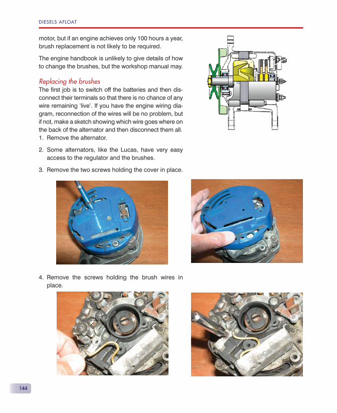
DIESELS AFLOAT
144
motor, but if an engine achieves only 100 hours a year, brush replacement is not likely to be required.
The engine handbook is unlikely to give details of how to change the brushes, but the workshop manual may.
Replacing the brushesThe fi rst job is to switch off the batteries and then dis-connect their terminals so that there is no chance of any wire remaining ‘live’. If you have the engine wiring dia-gram, reconnection of the wires will be no problem, but if not, make a sketch showing which wire goes where on the back of the alternator and then disconnect them all.
Remove the alternator.
Some alternators, like the Lucas, have very easy access to the regulator and the brushes.
Remove the two screws holding the cover in place.
Remove the screws holding the brush wires in place.
1.
2.
3.
4.
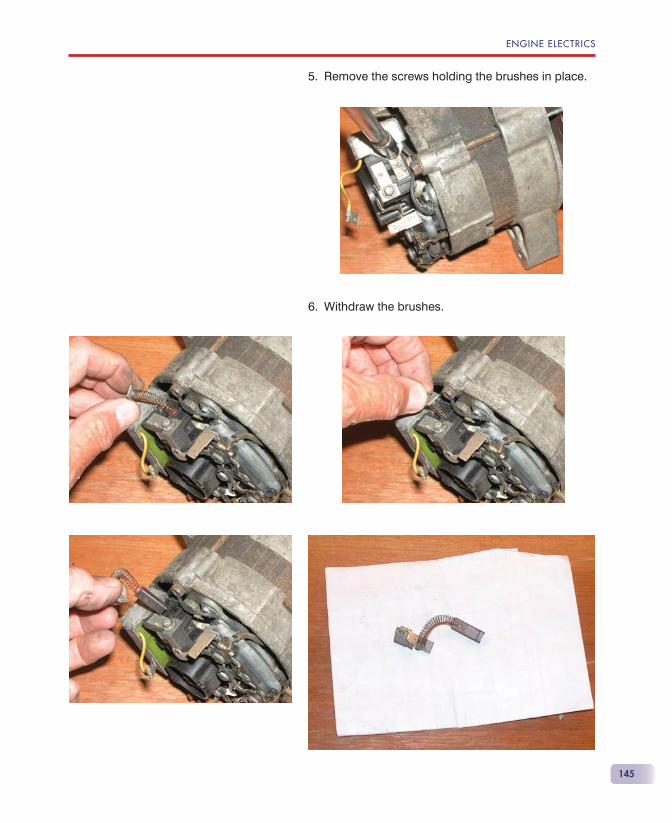
ENGINE ELECTRICS
145
Remove the screws holding the brushes in place.
Withdraw the brushes.
5.
6.
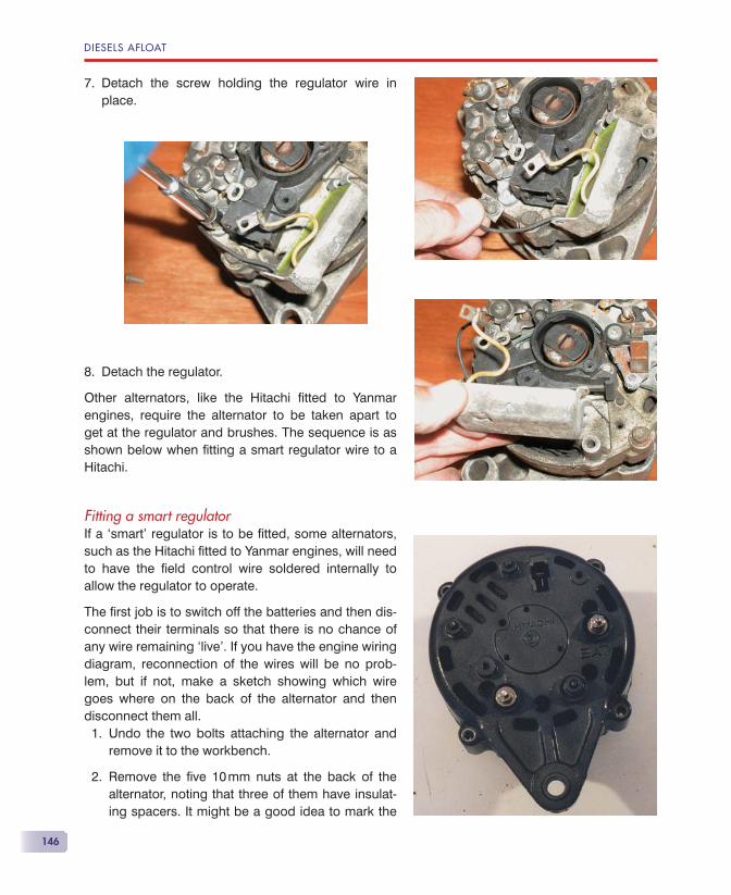
DIESELS AFLOAT
146
Detach the screw holding the regulator wire in place.
Detach the regulator.
Other alternators, like the Hitachi fi tted to Yanmar engines, require the alternator to be taken apart to get at the regulator and brushes. The sequence is as shown below when fi tting a smart regulator wire to a Hitachi.
Fitting a smart regulatorIf a ‘smart’ regulator is to be fi tted, some alternators, such as the Hitachi fi tted to Yanmar engines, will need to have the fi eld control wire soldered internally to allow the regulator to operate.
The fi rst job is to switch off the batteries and then dis-connect their terminals so that there is no chance of any wire remaining ‘live’. If you have the engine wiring diagram, reconnection of the wires will be no prob-lem, but if not, make a sketch showing which wire goes where on the back of the alternator and then disconnect them all.
Undo the two bolts attaching the alternator and remove it to the workbench.
Remove the fi ve 10 mm nuts at the back of the alternator, noting that three of them have insulat-ing spacers. It might be a good idea to mark the
7.
8.
1.
2.
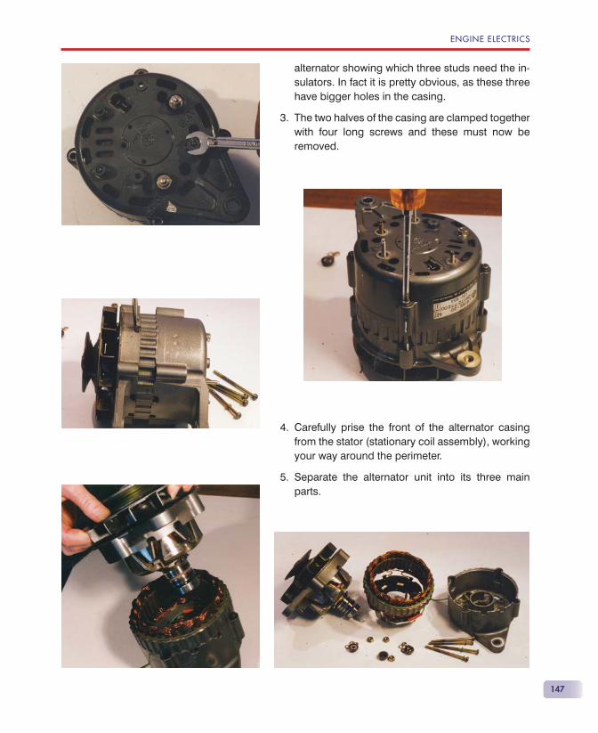
ENGINE ELECTRICS
147
alternator showing which three studs need the in-sulators. In fact it is pretty obvious, as these three have bigger holes in the casing.
The two halves of the casing are clamped together with four long screws and these must now be removed.
Carefully prise the front of the alternator casing from the stator (stationary coil assembly), working your way around the perimeter.
Separate the alternator unit into its three main parts.
3.
4.
5.
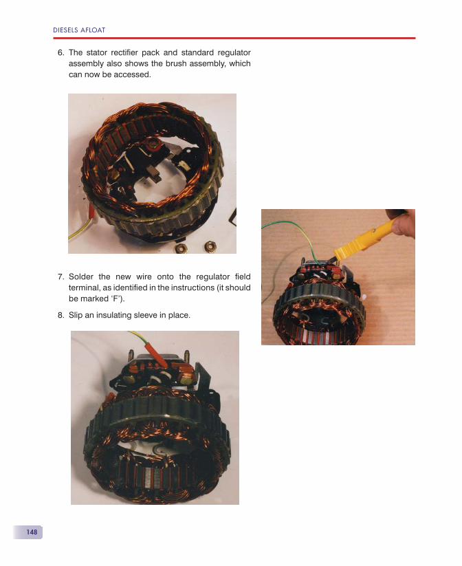
DIESELS AFLOAT
148
The stator rectifi er pack and standard regulator assembly also shows the brush assembly, which can now be accessed.
Solder the new wire onto the regulator fi eld terminal, as identifi ed in the instructions (it should be marked ‘F’).
Slip an insulating sleeve in place.
6.
7.
8.
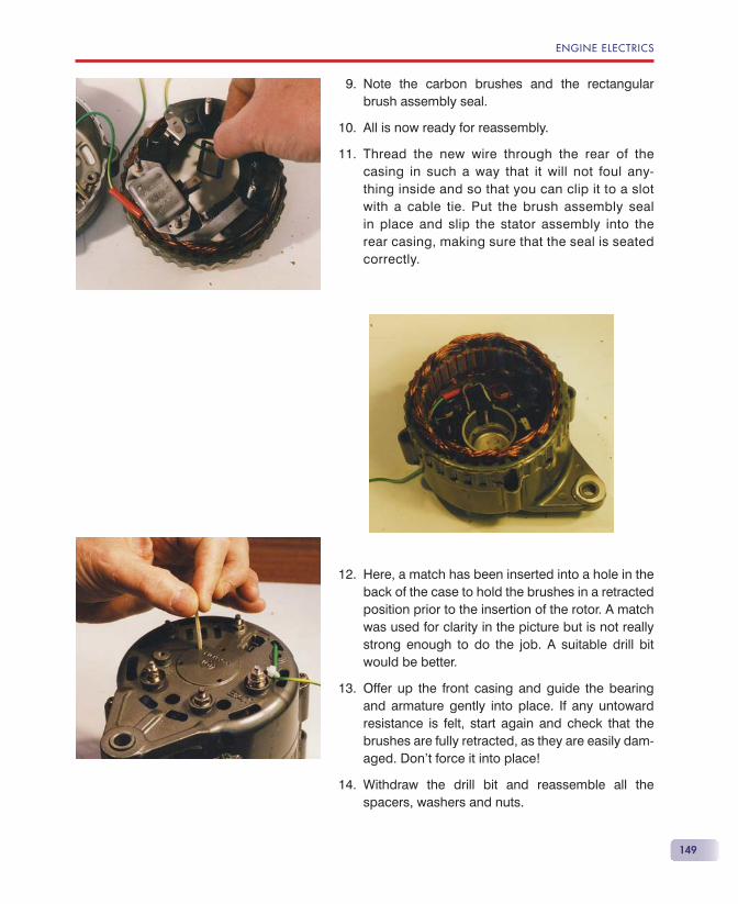
ENGINE ELECTRICS
149
Note the carbon brushes and the rectangular brush assembly seal.
All is now ready for reassembly.
Thread the new wire through the rear of the casing in such a way that it will not foul any-thing inside and so that you can clip it to a slot with a cable tie. Put the brush assembly seal in place and slip the stator assembly into the rear casing, making sure that the seal is seated correctly.
Here, a match has been inserted into a hole in the back of the case to hold the brushes in a retracted position prior to the insertion of the rotor. A match was used for clarity in the picture but is not really strong enough to do the job. A suitable drill bit would be better.
Offer up the front casing and guide the bearing and armature gently into place. If any untoward resistance is felt, start again and check that the brushes are fully retracted, as they are easily dam-aged. Don’t force it into place!
Withdraw the drill bit and reassemble all the spacers, washers and nuts.
9.
10.
11.
12.
13.
14.
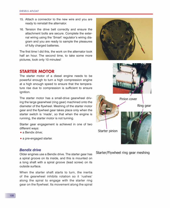
DIESELS AFLOAT
150
Attach a connector to the new wire and you are ready to reinstall the alternator.
Tension the drive belt correctly and ensure the attachment bolts are secure. Complete the exter-nal wiring using the ‘Smart’ regulator’s wiring dia-gram and you are ready to sample the pleasures of fully charged batteries.
The fi rst time I did this, the work on the alternator took half an hour. The second time, to take some more pictures, took only 10 minutes!
STARTER MOTORThe starter motor of a diesel engine needs to be powerful enough to turn a high compression engine at a high enough speed to ensure that the tempera-ture rise due to compression is suffi cient to ensure ignition.
The starter motor has a small-drive gearwheel driv-ing the large gearwheel (ring gear) machined onto the diameter of the fl ywheel. Meshing of the starter motor gear and the fl ywheel gear takes place only when the starter switch is ‘made’, so that when the engine is running, the starter motor is not turning.
Starter gear engagement is achieved in one of two different ways:
• a Bendix drive;
• a pre-engaged starter.
Bendix driveOlder engines use a Bendix drive. The starter gear has a spiral groove on its inside, and this is mounted on a long shaft with a spiral groove (lead screw) on its outside surface.
When the starter shaft starts to turn, the inertia of the gearwheel inhibits rotation so it ‘rushes’ along the spiral to engage with the starter ring gear on the flywheel. Its movement along the spiral
15.
16.
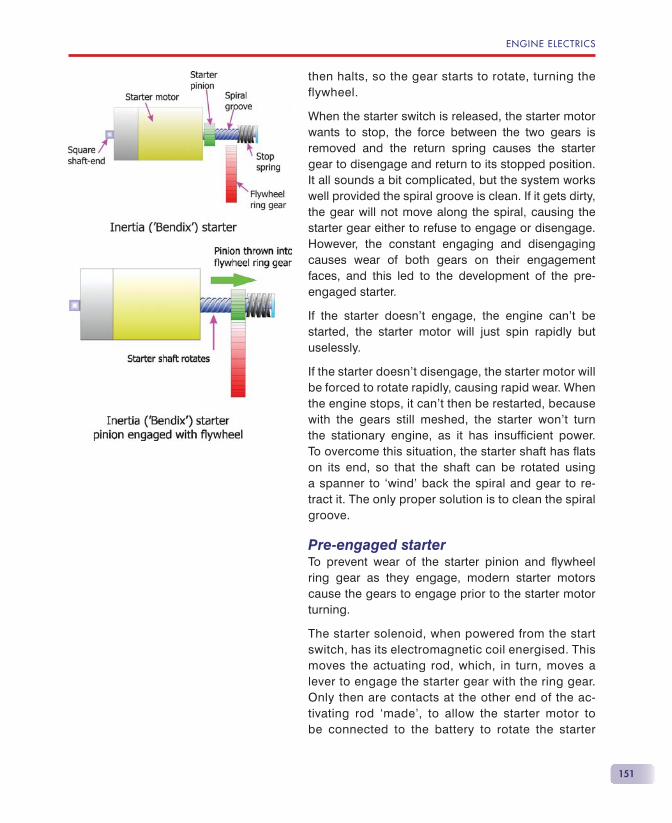
ENGINE ELECTRICS
151
then halts, so the gear starts to rotate, turning the flywheel.
When the starter switch is released, the starter motor wants to stop, the force between the two gears is removed and the return spring causes the starter gear to disengage and return to its stopped position. It all sounds a bit complicated, but the system works well provided the spiral groove is clean. If it gets dirty, the gear will not move along the spiral, causing the starter gear either to refuse to engage or disengage. However, the constant engaging and disengaging causes wear of both gears on their engagement faces, and this led to the development of the pre-engaged starter.
If the starter doesn’t engage, the engine can’t be started, the starter motor will just spin rapidly but uselessly.
If the starter doesn’t disengage, the starter motor will be forced to rotate rapidly, causing rapid wear. When the engine stops, it can’t then be restarted, because with the gears still meshed, the starter won’t turn the stationary engine, as it has insuffi cient power. To overcome this situation, the starter shaft has fl ats on its end, so that the shaft can be rotated using a spanner to ‘wind’ back the spiral and gear to re-tract it. The only proper solution is to clean the spiral groove.
Pre-engaged starterTo prevent wear of the starter pinion and fl ywheel ring gear as they engage, modern starter motors cause the gears to engage prior to the starter motor turning.
The starter solenoid, when powered from the start switch, has its electromagnetic coil energised. This moves the actuating rod, which, in turn, moves a lever to engage the starter gear with the ring gear. Only then are contacts at the other end of the ac-tivating rod ‘made’, to allow the starter motor to be connected to the battery to rotate the starter
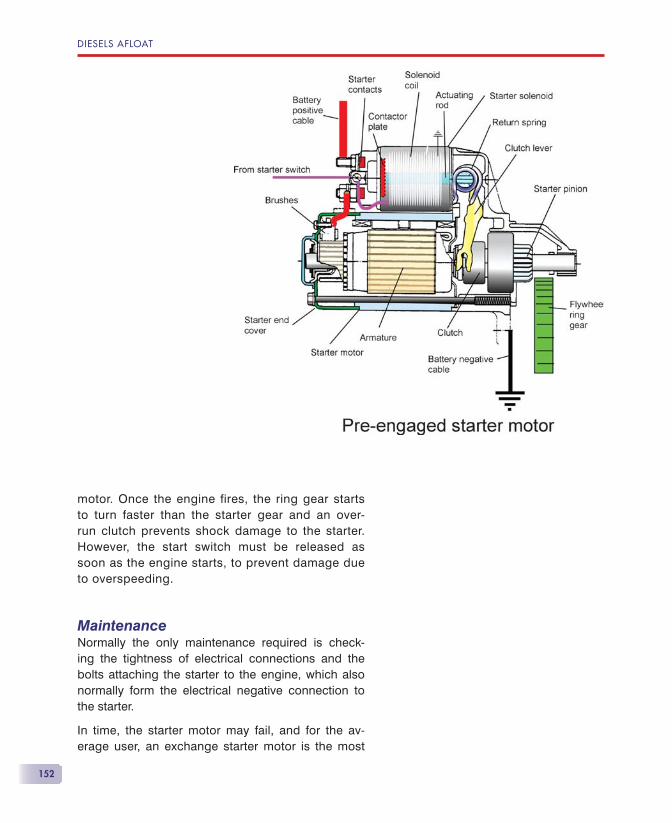
DIESELS AFLOAT
152
motor. Once the engine fires, the ring gear starts to turn faster than the starter gear and an over-run clutch prevents shock damage to the starter. However, the start switch must be released as soon as the engine starts, to prevent damage due to overspeeding.
MaintenanceNormally the only maintenance required is check-ing the tightness of electrical connections and the bolts attaching the starter to the engine, which also normally form the electrical negative connection to the starter.
In time, the starter motor may fail, and for the av-erage user, an exchange starter motor is the most
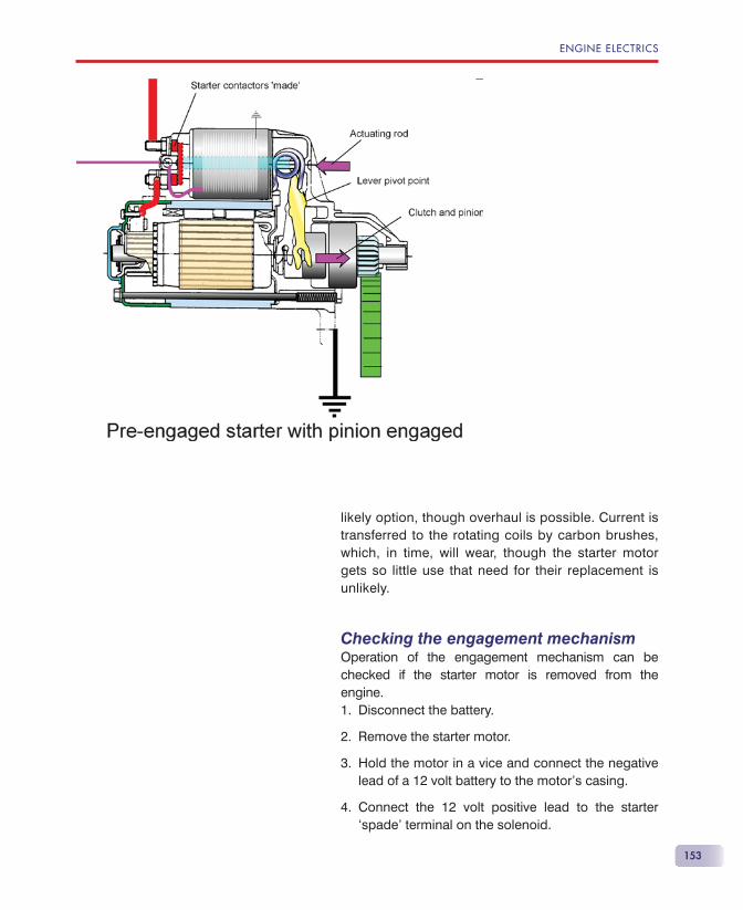
ENGINE ELECTRICS
153
likely option, though overhaul is possible. Current is transferred to the rotating coils by carbon brushes, which, in time, will wear, though the starter motor gets so little use that need for their replacement is unlikely.
Checking the engagement mechanismOperation of the engagement mechanism can be checked if the starter motor is removed from the engine.
Disconnect the battery.
Remove the starter motor.
Hold the motor in a vice and connect the negative lead of a 12 volt battery to the motor’s casing.
Connect the 12 volt positive lead to the starter ‘spade’ terminal on the solenoid.
1.
2.
3.
4.
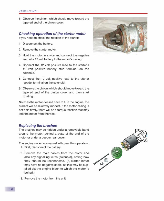
DIESELS AFLOAT
154
Observe the pinion, which should move toward the tapered end of the pinion cover.
Checking operation of the starter motorIf you need to check the rotation of the starter:
Disconnect the battery.
Remove the starter motor.
Hold the motor in a vice and connect the negative lead of a 12 volt battery to the motor’s casing.
Connect the 12 volt positive lead to the starter’s 12 volt positive battery stud terminal on the solenoid.
Connect the 12 volt positive lead to the starter ‘spade’ terminal on the solenoid.
Observe the pinion, which should move toward thetapered end of the pinion cover and then start rotating.
Note: as the motor doesn’t have to turn the engine, the current will be relatively modest. If the motor casing is not held fi rmly, there will be a torque reaction that may jerk the motor from the vice.
Replacing the brushesThe brushes may be hidden under a removable band around the motor, behind a plate at the end of the motor or under a deeper rear cover.
The engine workshop manual will cover this operation.First, disconnect the battery.
Remove the main cables from the motor and also any signalling wires (solenoid), noting how they should be reconnected. (A starter motor may have no negative cable, as this may be sup-plied via the engine block to which the motor is bolted.)
Remove the motor from the unit.
5.
1.
2.
3.
4.
5.
6.
1.
2.
3.
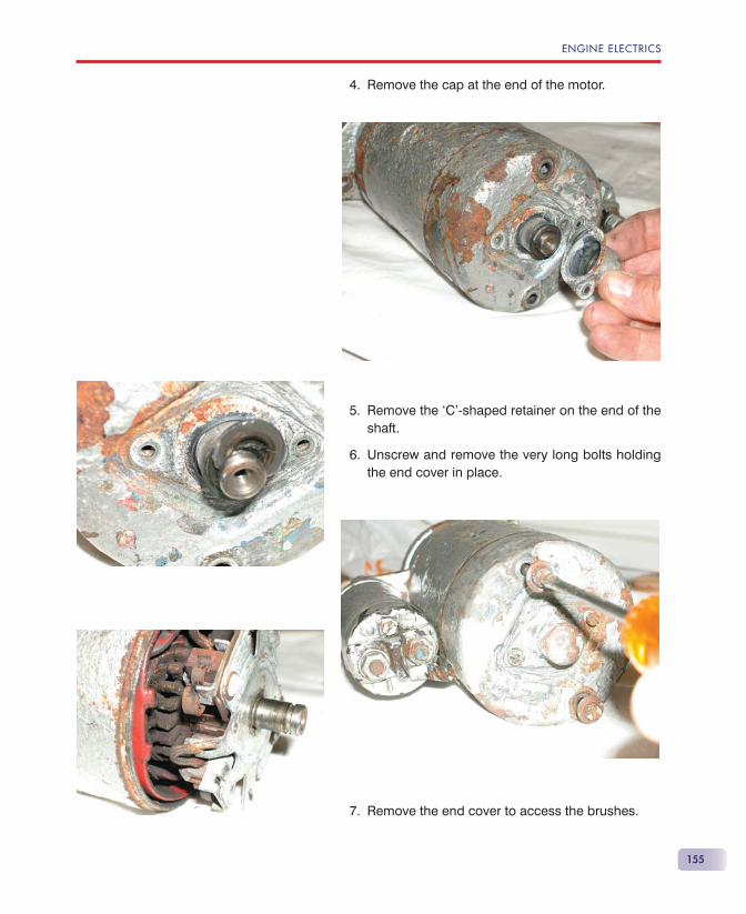
ENGINE ELECTRICS
155
Remove the cap at the end of the motor.
Remove the ‘C’-shaped retainer on the end of the shaft.
Unscrew and remove the very long bolts holding the end cover in place.
Remove the end cover to access the brushes.
4.
5.
6.
7.
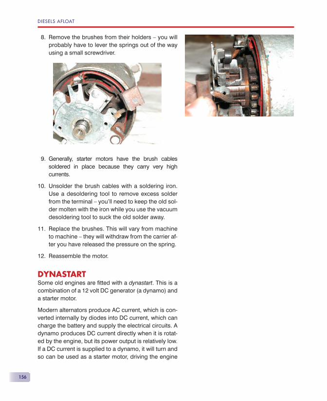
DIESELS AFLOAT
156
Remove the brushes from their holders — you will probably have to lever the springs out of the way using a small screwdriver.
Generally, starter motors have the brush cables soldered in place because they carry very high currents.
Unsolder the brush cables with a soldering iron. Use a desoldering tool to remove excess solder from the terminal — you’ll need to keep the old sol-der molten with the iron while you use the vacuum desoldering tool to suck the old solder away.
Replace the brushes. This will vary from machine to machine — they will withdraw from the carrier af-ter you have released the pressure on the spring.
Reassemble the motor.
DYNASTARTSome old engines are fi tted with a dynastart. This is a combination of a 12 volt DC generator (a dynamo) and a starter motor.
Modern alternators produce AC current, which is con-verted internally by diodes into DC current, which can charge the battery and supply the electrical circuits. A dynamo produces DC current directly when it is rotat-ed by the engine, but its power output is relatively low. If a DC current is supplied to a dynamo, it will turn and so can be used as a starter motor, driving the engine
8.
9.
10.
11.
12.
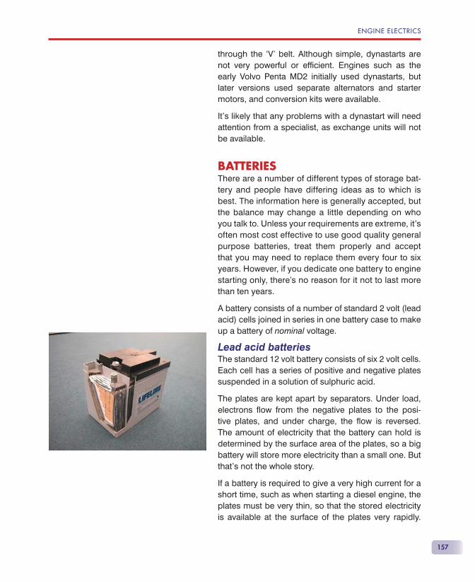
ENGINE ELECTRICS
157
through the ‘V’ belt. Although simple, dynastarts are not very powerful or effi cient. Engines such as the early Volvo Penta MD2 initially used dynastarts, but later versions used separate alternators and starter motors, and conversion kits were available.
It’s likely that any problems with a dynastart will need attention from a specialist, as exchange units will not be available.
BATTERIESThere are a number of different types of storage bat-tery and people have differing ideas as to which is best. The information here is generally accepted, but the balance may change a little depending on who you talk to. Unless your requirements are extreme, it’s often most cost effective to use good quality general purpose batteries, treat them properly and accept that you may need to replace them every four to six years. However, if you dedicate one battery to engine starting only, there’s no reason for it not to last more than ten years.
A battery consists of a number of standard 2 volt (lead acid) cells joined in series in one battery case to make up a battery of nominal voltage.
Lead acid batteriesThe standard 12 volt battery consists of six 2 volt cells. Each cell has a series of positive and negative plates suspended in a solution of sulphuric acid.
The plates are kept apart by separators. Under load, electrons fl ow from the negative plates to the posi-tive plates, and under charge, the fl ow is reversed. The amount of electricity that the battery can hold is determined by the surface area of the plates, so a big battery will store more electricity than a small one. But that’s not the whole story.
If a battery is required to give a very high current for a short time, such as when starting a diesel engine, the plates must be very thin, so that the stored electricity is available at the surface of the plates very rapidly.
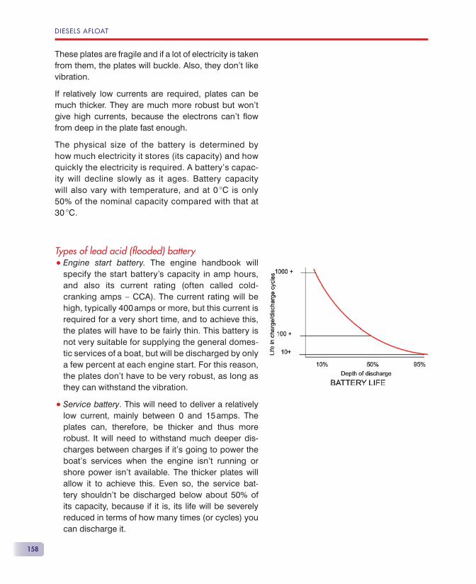
DIESELS AFLOAT
158
These plates are fragile and if a lot of electricity is taken from them, the plates will buckle. Also, they don’t like vibration.
If relatively low currents are required, plates can be much thicker. They are much more robust but won’t give high currents, because the electrons can’t fl ow from deep in the plate fast enough.
The physical size of the battery is determined by how much electricity it stores (its capacity) and how quickly the electricity is required. A battery’s capac-ity will decline slowly as it ages. Battery capacity will also vary with temperature, and at 0 �C is only 50% of the nominal capacity compared with that at 30 �C.
Types of lead acid (fl ooded) battery• Engine start battery. The engine handbook will
specify the start battery’s capacity in amp hours, and also its current rating (often called cold-cranking amps — CCA). The current rating will be high, typically 400 amps or more, but this current is required for a very short time, and to achieve this, the plates will have to be fairly thin. This battery is not very suitable for supplying the general domes-tic services of a boat, but will be discharged by only a few percent at each engine start. For this reason, the plates don’t have to be very robust, as long as they can withstand the vibration.
• Service battery. This will need to deliver a relatively low current, mainly between 0 and 15 amps. The plates can, therefore, be thicker and thus more robust. It will need to withstand much deeper dis-charges between charges if it’s going to power the boat’s services when the engine isn’t running or shore power isn’t available. The thicker plates will allow it to achieve this. Even so, the service bat-tery shouldn’t be discharged below about 50% of its capacity, because if it is, its life will be severely reduced in terms of how many times (or cycles) you can discharge it.
ENGINE ELECTRICS
159
General purpose batteriesUnless the demands of engine starting are severe, you can use a battery that will fulfi l both engine starting and service requirements satisfactorily. It will do neither job perfectly, but the average yachtsman will probably fi nd this type of battery perfectly OK. They are often sold as marine batteries or heavy duty batteries.
Deep cycle batteriesDeep cycle batteries have much thicker plates and are heavy. The ‘deep cycle’ adjective doesn’t mean that you can discharge the battery much more than 50%, but it does mean that you can do so a greater number of times. Unless the battery is a traction battery that is extremely heavy duty and designed for fork-lift trucks, golf carts and the like, it will rapidly be destroyed by fully discharging it.
Some batteries are labelled ‘heavy duty’ or ‘deep cy-cle’ when in reality they do not deserve the title, and it’s often diffi cult to get the facts. One battery company that does publish information is Optima, from Sweden, whose Optima ‘Blue Top’ marine battery claims to have a BCI/SAE cycle life of 350 cycles of fully charged to 100% discharged. This is an excellent fi gure.
Batteries should be recharged as soon as possible after being discharged, to prolong their life.
Maintenance-free batteriesNormal batteries lose water from their electrolyte dur-ing recharging and need to be topped up regularly with distilled or ionised water. Explosive hydrogen gas is given off in this process.
If the battery has more water to start with, has its charging current restricted and is almost entirely sealed, it will not need to be topped up during its lifetime. These mainte-nance-free batteries have no means of being topped up. They must not be charged as rapidly as a standard battery and thus will take longer to charge, but if you have a stan-dard regulator, you won’t notice the difference. A mains battery charger will need to be set for maintenance-free charging. These batteries lose very little charge during

DIESELS AFLOAT
160
storage and should be capable of starting an engine after being stored for 18 months. A standard battery will lose up to 1½% of its charge every week it’s idle.
Some so-called ‘maintenance-free’ batteries have caps to each cell. If it’s not sealed, it isn’t maintenance-free and will need to be topped up as required.
AGM batteriesAbsorbed glass mat batteries have heavy duty plates separated by glass fi bre mats that absorb the electrolyte, so that there’s no free liquid in the bat-tery. The best are robust, are virtually non-spill and withstand vibration well. They tolerate high charging voltages and have low self-discharge rates and some, such as ‘Lifeline’, can be used for engine starting as well as being deep cycle ‘service’ batteries. AGM bat-teries have good deep cycle/life expectancy.
Gel batteriesThe electrolyte is in the form of a gel and the plates are thin to allow the electrolyte to diffuse into the plates. Gel batteries are sealed, so can’t be topped up, and the charge voltage must be kept low so that the battery does not gas. Very strict regulation of charging current and voltage is required, and gel batteries take longer to recharge than wet ones.
Nickel-Cadmium (Ni-Cd) batteriesNickel-Cadmium batteries are very robust and have a very long life, but are very expensive. They can be deep cycled thousands of times, so are very suited to use on a sailing boat. Because they lose the ability to be fully recharged unless they are fully discharged, you really need two service battery banks so that one can be fully discharged before recharging. Each bank is used alternately. Their cost is justifi ed only if you’re going to keep the boat for a long time and are going to make heavy demands on your batteries.
Measuring state of chargeThe state of charge (how fully the battery is charged) can be determined by means of a hydrometer, which
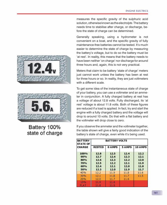
ENGINE ELECTRICS
161
measures the specifi c gravity of the sulphuric acid solution, otherwise known as the electrolyte. The battery needs time to stabilise after charge, or discharge, be-fore the state of charge can be determined.
Generally speaking, using a hydrometer is not convenient on a boat, and the specifi c gravity of fully maintenance-free batteries cannot be tested. It’s much easier to determine the state of charge by measuring the battery’s voltage, but to do so the battery must be ‘at rest’. In reality, this means that the battery needs to have been neither ‘on charge’ nor discharge for around three hours and, again, this is not very practical.
Meters that claim to be battery ‘state of charge’ meters just cannot work unless the battery has been at rest for three hours or so. In reality, they are just voltmeters with a different scale.
To get some idea of the instantaneous state of charge of your battery, you can use a voltmeter and an amme-ter in conjunction. A fully charged battery at rest has a voltage of about 12.8 volts. Fully discharged, its ‘at rest’ voltage is about 11.8 volts. Both of these fi gures are reduced if a load is applied. In fact, try and start the engine with a fully charged battery and the voltage will drop to around 10 volts. Do that with a fl at battery and the voltmeter will drop close to zero.
If you observe the ammeter and the voltmeter together, the table shown will give a fairly good indication of the battery’s state of charge, even while it’s being used.
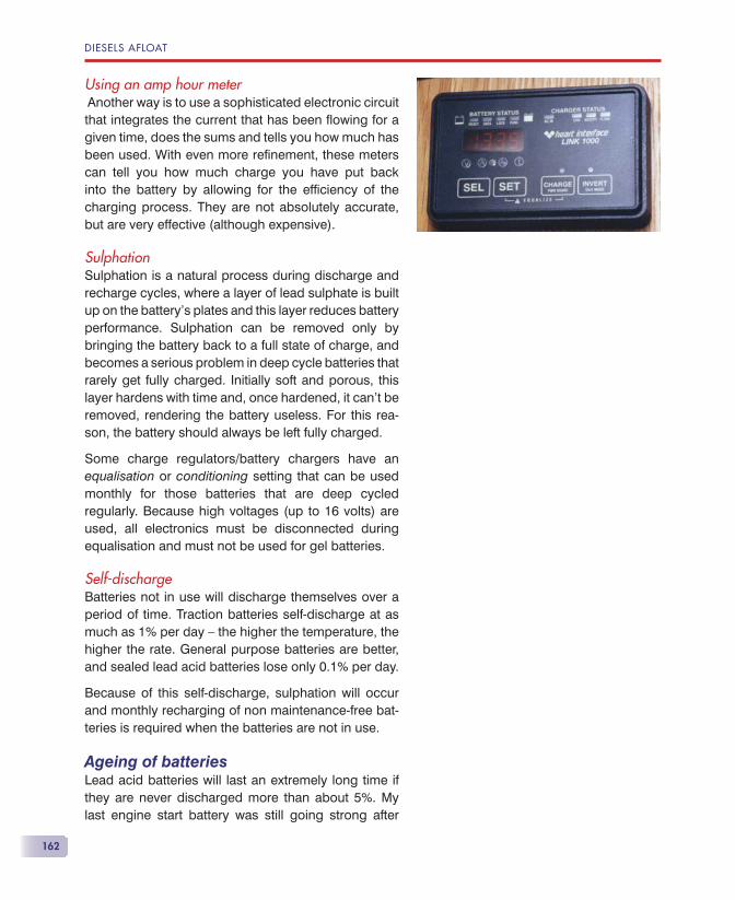
DIESELS AFLOAT
162
Using an amp hour meter Another way is to use a sophisticated electronic circuit that integrates the current that has been fl owing for a given time, does the sums and tells you how much has been used. With even more refi nement, these meters can tell you how much charge you have put back into the battery by allowing for the effi ciency of the charging process. They are not absolutely accurate, but are very effective (although expensive).
SulphationSulphation is a natural process during discharge and recharge cycles, where a layer of lead sulphate is built up on the battery’s plates and this layer reduces battery performance. Sulphation can be removed only by bringing the battery back to a full state of charge, and becomes a serious problem in deep cycle batteries that rarely get fully charged. Initially soft and porous, this layer hardens with time and, once hardened, it can’t be removed, rendering the battery useless. For this rea-son, the battery should always be left fully charged.
Some charge regulators/battery chargers have an equalisation or conditioning setting that can be used monthly for those batteries that are deep cycled regularly. Because high voltages (up to 16 volts) are used, all electronics must be disconnected during equalisation and must not be used for gel batteries.
Self-dischargeBatteries not in use will discharge themselves over a period of time. Traction batteries self-discharge at as much as 1% per day — the higher the temperature, the higher the rate. General purpose batteries are better, and sealed lead acid batteries lose only 0.1% per day.
Because of this self-discharge, sulphation will occur and monthly recharging of non maintenance-free bat-teries is required when the batteries are not in use.
Ageing of batteriesLead acid batteries will last an extremely long time if they are never discharged more than about 5%. My last engine start battery was still going strong after
ENGINE ELECTRICS
163
12 years. Service batteries, because of their regular cycling, will slowly suffer from irreversible sulphation and their effective capacity will fall. Regularly fully charged and never discharged below 50%, you may expect fi ve or six years, maybe more. Mistreated batteries may not last two seasons.
If one cell fails, this will pull the voltage down, not only on that battery, but also on the whole bank. If the bat-tery bank voltage has fallen to 12.5 volts or so, after being fully charged and rested for 12 hours, you can suspect a failure of one cell. There are three ways of checking which battery has the bad cell.
• Measure the specifi c gravity of each cell with a hydrometer. The bad cell will have a much lower reading.
• Disconnect all the batteries. Wait about 12 hours and measure the voltage of each battery. The bad bat-tery will still be 12.5 volts or less, the others should have recovered a little.
• Disconnect all but one battery at a time and use it to turn the engine over. You’ll need to prevent the engine starting by setting the stop control to stop. The battery that drops below 9.5 volts has the bad cell.
If the whole battery is suffering from sulphation, its real capacity will be reduced. To test this, discharge the fully charged battery by using a number of lights of known wattage for long enough to discharge it by 25% of its nominal capacity. Now measure its specifi c grav-ity or its ‘at rest’ voltage to determine its actual state of charge. The difference between the actual state of charge and the nominal 75% indicates the reduction in capacity.
So, for a nominal 200 amp hour battery, you want to remove 50 amp hours to reduce it to 75%. Four 10 watt bulbs on a 12 volt system would take 3.33 amps and would need to be run for 15 hours to remove the 50 amp hours. If, after 12 hours at rest, voltage is now 12.3 volts, the actual state of charge is only 50%, rather than the nominal 75%. The lights have removed
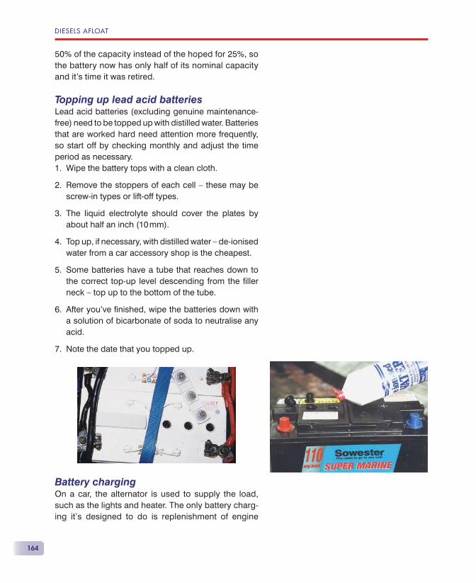
DIESELS AFLOAT
164
50% of the capacity instead of the hoped for 25%, so the battery now has only half of its nominal capacity and it’s time it was retired.
Topping up lead acid batteriesLead acid batteries (excluding genuine maintenance-free) need to be topped up with distilled water. Batteries that are worked hard need attention more frequently, so start off by checking monthly and adjust the time period as necessary.
Wipe the battery tops with a clean cloth.
Remove the stoppers of each cell — these may be screw-in types or lift-off types.
The liquid electrolyte should cover the plates by about half an inch (10 mm).
Top up, if necessary, with distilled water — de-ionised water from a car accessory shop is the cheapest.
Some batteries have a tube that reaches down to the correct top-up level descending from the fi ller neck — top up to the bottom of the tube.
After you’ve fi nished, wipe the batteries down with a solution of bicarbonate of soda to neutralise any acid.
Note the date that you topped up.
Battery chargingOn a car, the alternator is used to supply the load, such as the lights and heater. The only battery charg-ing it’s designed to do is replenishment of engine
1.
2.
3.
4.
5.
6.
7.
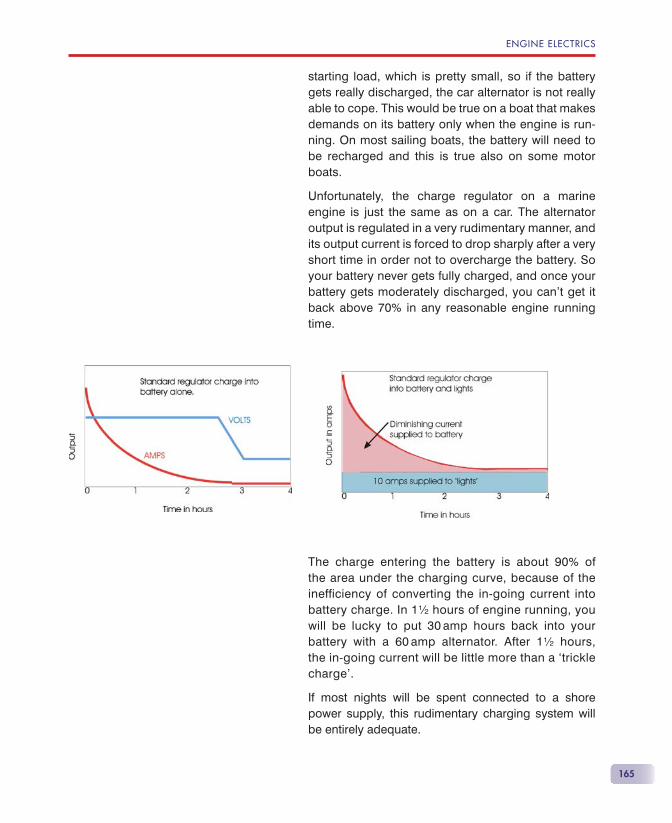
ENGINE ELECTRICS
165
starting load, which is pretty small, so if the battery gets really discharged, the car alternator is not really able to cope. This would be true on a boat that makes demands on its battery only when the engine is run-ning. On most sailing boats, the battery will need to be recharged and this is true also on some motor boats.
Unfortunately, the charge regulator on a marine engine is just the same as on a car. The alternator output is regulated in a very rudimentary manner, and its output current is forced to drop sharply after a very short time in order not to overcharge the battery. So your battery never gets fully charged, and once your battery gets moderately discharged, you can’t get it back above 70% in any reasonable engine running time.
The charge entering the battery is about 90% of the area under the charging curve, because of the inefficiency of converting the in-going current into battery charge. In 1½ hours of engine running, you will be lucky to put 30 amp hours back into your battery with a 60 amp alternator. After 1½ hours, the in-going current will be little more than a ‘trickle charge’.
If most nights will be spent connected to a shore power supply, this rudimentary charging system will be entirely adequate.
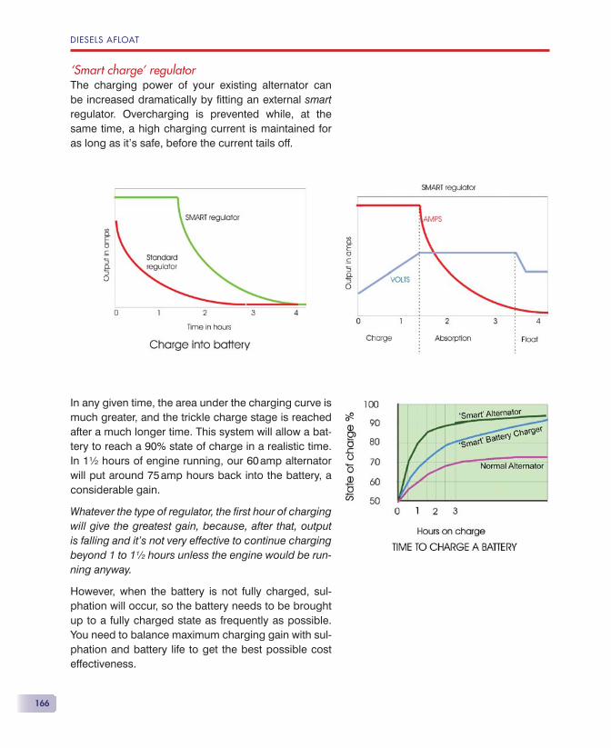
DIESELS AFLOAT
166
‘Smart charge’ regulatorThe charging power of your existing alternator can be increased dramatically by fi tting an external smart regulator. Overcharging is prevented while, at the same time, a high charging current is maintained for as long as it’s safe, before the current tails off.
In any given time, the area under the charging curve is much greater, and the trickle charge stage is reached after a much longer time. This system will allow a bat-tery to reach a 90% state of charge in a realistic time. In 1½ hours of engine running, our 60 amp alternator will put around 75 amp hours back into the battery, a considerable gain.
Whatever the type of regulator, the fi rst hour of charging will give the greatest gain, because, after that, output is falling and it’s not very effective to continue charging beyond 1 to 1½ hours unless the engine would be run-ning anyway.
However, when the battery is not fully charged, sul-phation will occur, so the battery needs to be brought up to a fully charged state as frequently as possible. You need to balance maximum charging gain with sul-phation and battery life to get the best possible cost effectiveness.
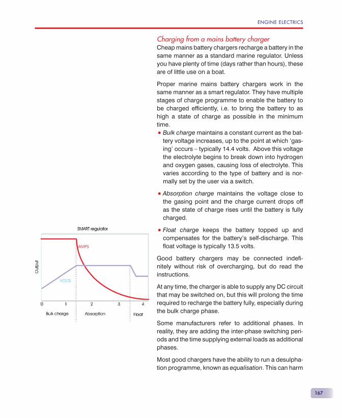
ENGINE ELECTRICS
167
Charging from a mains battery chargerCheap mains battery chargers recharge a battery in the same manner as a standard marine regulator. Unless you have plenty of time (days rather than hours), these are of little use on a boat.
Proper marine mains battery chargers work in the same manner as a smart regulator. They have multiple stages of charge programme to enable the battery to be charged effi ciently, i.e. to bring the battery to as high a state of charge as possible in the minimum time.
• Bulk charge maintains a constant current as the bat-tery voltage increases, up to the point at which ‘gas-ing’ occurs — typically 14.4 volts. Above this voltage the electrolyte begins to break down into hydrogen and oxygen gases, causing loss of electrolyte. This varies according to the type of battery and is nor-mally set by the user via a switch.
• Absorption charge maintains the voltage close to the gasing point and the charge current drops off as the state of charge rises until the battery is fully charged.
• Float charge keeps the battery topped up and compensates for the battery’s self-discharge. This fl oat voltage is typically 13.5 volts.
Good battery chargers may be connected indefi -nitely without risk of overcharging, but do read the instructions.
At any time, the charger is able to supply any DC circuit that may be switched on, but this will prolong the time required to recharge the battery fully, especially during the bulk charge phase.
Some manufacturers refer to additional phases. In reality, they are adding the inter-phase switching peri-ods and the time supplying external loads as additional phases.
Most good chargers have the ability to run a desulpha-tion programme, known as equalisation. This can harm
DIESELS AFLOAT
168
the battery if used incorrectly, so make full reference to the charger’s instructions, especially with regard to battery type, frequency of use and time the high volt-age is applied.
If the requirement is to ‘top up’ your battery over-night, then its output in amps is as important as its programmed charge ability. For this you need to know how much you are likely to have discharged your battery or the capacity of the battery bank. Generally, these two will be closely linked, so it’s normal to match the charger output to the capacity of the battery bank.
A good starting point is that the charger’s output should be about 10% of the battery capacity (ignore the engine start battery). If high battery loads will be applied at the same time as charging, you may need to add this extra load to the output of the charger.
If you have a 400 amp hour battery bank, then a 40 amp charger is appropriate. If there is a continuous require-ment for a further 10 amps, for a fridge and a cabin heater for example, this 10 amps should be added to give a 50 amp charger.

169
he gearbox, often referred to as the marine gear, has three purposes:
• to reduce the maximum speed at which the propel-ler rotates;
• to enable both forward and astern rotation of the propeller;
• to enable the propeller to remain stationary while the engine is running.
Unlike a car gearbox, there’s only one forward gear, although one manufacturer produces a two-speed gear for high-speed motor cruisers, and the clutch is contained within the gearbox.
SPEED REDUCTIONModern engines run at too high a speed for normal operation of the propeller. The reduction gear ratio is normally between 2.0:1 and 3.0:1 and many manu-facturers have a number of different ratios, so that the engine can be tailored to the boat’s requirements. If you are planning to put a new engine in your boat, it’s best to discuss the required gear ratio with the engine supplier.
The Gearbox
T
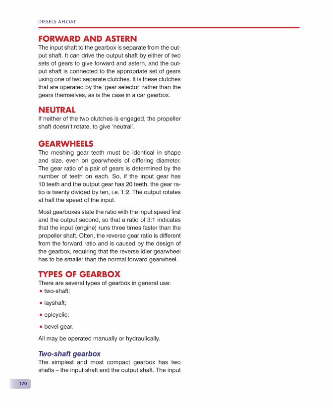
DIESELS AFLOAT
170
FORWARD AND ASTERNThe input shaft to the gearbox is separate from the out-put shaft. It can drive the output shaft by either of two sets of gears to give forward and astern, and the out-put shaft is connected to the appropriate set of gears using one of two separate clutches. It is these clutches that are operated by the ‘gear selector’ rather than the gears themselves, as is the case in a car gearbox.
NEUTRALIf neither of the two clutches is engaged, the propeller shaft doesn’t rotate, to give ‘neutral’.
GEARWHEELSThe meshing gear teeth must be identical in shape and size, even on gearwheels of differing diameter. The gear ratio of a pair of gears is determined by the number of teeth on each. So, if the input gear has10 teeth and the output gear has 20 teeth, the gear ra-tio is twenty divided by ten, i.e. 1:2. The output rotates at half the speed of the input.
Most gearboxes state the ratio with the input speed fi rst and the output second, so that a ratio of 3:1 indicates that the input (engine) runs three times faster than the propeller shaft. Often, the reverse gear ratio is different from the forward ratio and is caused by the design of the gearbox, requiring that the reverse idler gearwheel has to be smaller than the normal forward gearwheel.
TYPES OF GEARBOXThere are several types of gearbox in general use:
• two-shaft;
• layshaft;
• epicyclic;
• bevel gear.
All may be operated manually or hydraulically.
Two-shaft gearboxThe simplest and most compact gearbox has two shafts — the input shaft and the output shaft. The input
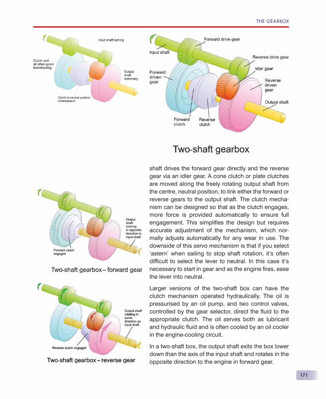
THE GEARBOX
171
shaft drives the forward gear directly and the reverse gear via an idler gear. A cone clutch or plate clutches are moved along the freely rotating output shaft from the centre, neutral position, to link either the forward or reverse gears to the output shaft. The clutch mecha-nism can be designed so that as the clutch engages, more force is provided automatically to ensure full engagement. This simplifi es the design but requires accurate adjustment of the mechanism, which nor-mally adjusts automatically for any wear in use. The downside of this servo mechanism is that if you select ‘astern’ when sailing to stop shaft rotation, it’s often diffi cult to select the lever to neutral. In this case it’s necessary to start in gear and as the engine fi res, ease the lever into neutral.
Larger versions of the two-shaft box can have the clutch mechanism operated hydraulically. The oil is pressurised by an oil pump, and two control valves, controlled by the gear selector, direct the fl uid to the appropriate clutch. The oil serves both as lubricant and hydraulic fl uid and is often cooled by an oil cooler in the engine-cooling circuit.
In a two-shaft box, the output shaft exits the box lower down than the axis of the input shaft and rotates in the opposite direction to the engine in forward gear.
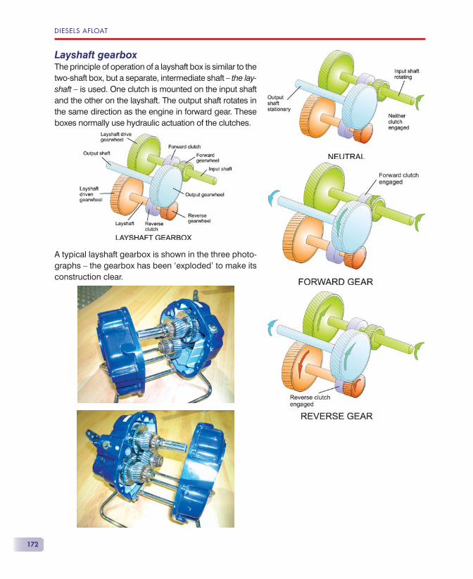
DIESELS AFLOAT
172
Layshaft gearboxThe principle of operation of a layshaft box is similar to the two-shaft box, but a separate, intermediate shaft — the lay-shaft — is used. One clutch is mounted on the input shaft and the other on the layshaft. The output shaft rotates in the same direction as the engine in forward gear. These boxes normally use hydraulic actuation of the clutches.
A typical layshaft gearbox is shown in the three photo-graphs — the gearbox has been ‘exploded’ to make its construction clear.
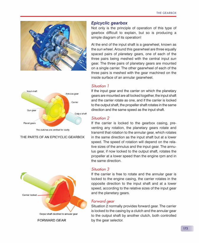
THE GEARBOX
173
Epicyclic gearboxNot only is the principle of operation of this type of gearbox diffi cult to explain, but so is producing a simple diagram of its operation!
At the end of the input shaft is a gearwheel, known as the sun wheel. Around this gearwheel are three equally spaced pairs of planetary gears, one of each of the three pairs being meshed with the central input sun gear. The three pairs of planetary gears are mounted on a single carrier. The other gearwheel of each of the three pairs is meshed with the gear machined on the inside surface of an annular gearwheel.
Situation 1If the input gear and the carrier on which the planetary gears are mounted are all locked together, the input shaft and the carrier rotate as one, and if the carrier is locked to the output shaft, the propeller shaft rotates in the same direction and the same speed as the input shaft.
Situation 2If the carrier is locked to the gearbox casing, pre-venting any rotation, the planetary gears rotate and transmit that rotation to the annular gear, which rotates in the same direction as the input shaft but at a lower speed. The speed of rotation will depend on the rela-tive sizes of the annulus and the input gear. The annu-lus gear, if now locked to the output shaft, rotates the propeller at a lower speed than the engine rpm and in the same direction.
Situation 3If the carrier is free to rotate and the annular gear is locked to the engine casing, the carrier rotates in the opposite direction to the input shaft and at a lower speed, according to the relative sizes of the input gear and the planetary gears.
Forward gearSituation 2 normally provides forward gear. The carrier is locked to the casing by a clutch and the annular gear to the output shaft by another clutch, both controlled by the gear selector.
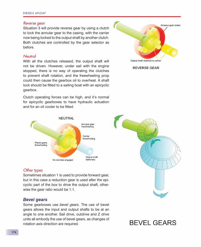
DIESELS AFLOAT
174
Reverse gearSituation 3 will provide reverse gear by using a clutch to lock the annular gear to the casing, with the carrier now being locked to the output shaft by another clutch. Both clutches are controlled by the gear selector as before.
NeutralWith all the clutches released, the output shaft will not be driven. However, under sail with the engine stopped, there is no way of operating the clutches to prevent shaft rotation, and the freewheeling prop could then cause the gearbox oil to overheat. A shaft lock should be fi tted to a sailing boat with an epicyclic gearbox.
Clutch operating forces can be high, and it’s normal for epicyclic gearboxes to have hydraulic actuation and for an oil cooler to be fi tted.
Other typesSometimes situation 1 is used to provide forward gear, but in this case a reduction gear is used after the epi-cyclic part of the box to drive the output shaft, other-wise the gear ratio would be 1:1.
Bevel gearsSome gearboxes use bevel gears. The use of bevel gears allows the input and output shafts to be at an angle to one another. Sail drive, outdrive and Z drive units all embody the use of bevel gears, as changes of rotation axis direction are required.
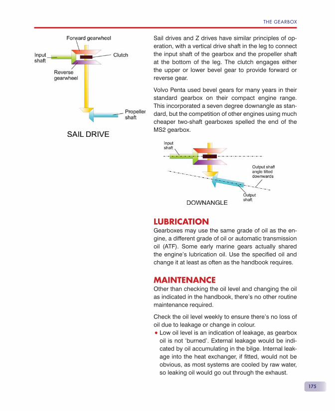
THE GEARBOX
175
Sail drives and Z drives have similar principles of op-eration, with a vertical drive shaft in the leg to connect the input shaft of the gearbox and the propeller shaft at the bottom of the leg. The clutch engages either the upper or lower bevel gear to provide forward or reverse gear.
Volvo Penta used bevel gears for many years in their standard gearbox on their compact engine range. This incorporated a seven degree downangle as stan-dard, but the competition of other engines using much cheaper two-shaft gearboxes spelled the end of the MS2 gearbox.
LUBRICATIONGearboxes may use the same grade of oil as the en-gine, a different grade of oil or automatic transmission oil (ATF). Some early marine gears actually shared the engine’s lubrication oil. Use the specifi ed oil and change it at least as often as the handbook requires.
MAINTENANCEOther than checking the oil level and changing the oil as indicated in the handbook, there’s no other routine maintenance required.
Check the oil level weekly to ensure there’s no loss of oil due to leakage or change in colour.
• Low oil level is an indication of leakage, as gearbox oil is not ‘burned’. External leakage would be indi-cated by oil accumulating in the bilge. Internal leak-age into the heat exchanger, if fi tted, would not be obvious, as most systems are cooled by raw water, so leaking oil would go out through the exhaust.
DIESELS AFLOAT
176
• A darkening of the oil indicates overheating. This may be due to excessive friction in the gearbox, slip-ping clutches or blockage of the heat exchanger if fi tted.
• A white emulsion indicates water contamination. This is likely to be leakage from the gearbox cooling jacket or heat exchanger if either is fi tted, or from the underwater seal in sail drive and Z drive units.
TROUBLESHOOTINGModern gearboxes are sturdy and generally give little trouble, however, they rely on their clutches being ad-justed properly. A slipping clutch will cause overheat-ing and, eventually, loss of drive.
Most clutches are self-adjusting.
• Mechanically selected clutches require that the operating cable moves the selector lever to the fully engaged position, and stretching of the oper-ating cable can cause incomplete selection of the clutches, resulting in clutch slip. Many handbooks will not give details of this adjustment, so you may need the workshop manual or a dealer’s help.
• Hydraulically operated clutches use the selector cable to operate the hydraulic selector valve, and, generally, adjustment is not so critical.
Loss of driveIf you experience loss of drive, you’ll need to check the rotation of the prop shaft and the movement of the gear selector arm on the gearbox.
Check that the selector lever moves to forward and reverse when the ‘Throttle/Gear’ lever is moved to forward and reverse.
If it does, check that full travel occurs.
If the selector lever doesn’t move, the problem is the cable or cockpit gear selector mechanism.
On a ‘dual station’ system, is the other selec-tor in neutral or the station selector control set appropriately?
1.
2.
3.
4.
Warning!
Ensure that nothing you are wearing or your hair can get entangled in the rotating machinery. Failure to heed this warning can be fatal!
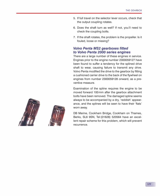
THE GEARBOX
177
If full travel on the selector lever occurs, check that the output coupling rotates.
Does the shaft turn as well? If not, you’ll need to check the coupling bolts.
If the shaft rotates, the problem is the propeller. Is it fouled, loose or missing?
Volvo Penta MS2 gearboxes fi ttedto Volvo Penta 2000 series enginesThere are a large number of these engines in service. Engines prior to the engine number 2300059127 have been found to suffer a tendency for the splined drive shaft to wear, causing failure to transmit any drive. Volvo Penta modifi ed the drive to the gearbox by fi tting a cushioned carrier drive to the back of the fl ywheel on engines from number 2300059128 onward, as a pre-ventive measure.
Examination of the spline requires the engine to be moved forward 100 mm after the gearbox attachment bolts have been removed. The damaged spline seems always to be accompanied by a dry, ‘reddish’ appear-ance, and the splines will be seen to have their ‘fl ats’ worn away.
DB Marine, Cookham Bridge, Cookham on Thames, Berks, SL6 9SN, Tel:(01628) 520564 have an excel-lent repair scheme for this problem, which will prevent recurrence.
5.
6.
7.

179
A rubber drive belt is used to drive the alterna-tor (or, on older engines, the dynamo). Correct tension is important — too tight and bearings
will suffer, too loose and slip will occur. Slip will cause overheating of the belt, leading to its premature failure, and also, where the tachometer is powered from the ‘W’ connection on the alternator, rpm will under-read. A broken drive belt will stop battery charging, but the engine will run.
On some engines, the water pump is also belt-driven. Failure of the drive belt will cause rapid overheating of the engine and prevent continued running.
Belt pulley alignment is also important for the lon-gevity of the belt, although this will normally be a problem only if the pulleys or alternator have been changed.
ADJUSTING THE TENSIONThe method of belt tension adjustment on the majority of engines is pretty crude.
Slacken the nut and bolt on the adjustment arm.
Slacken the main attachment pivot bolt.
1.
2.
Drive Belts
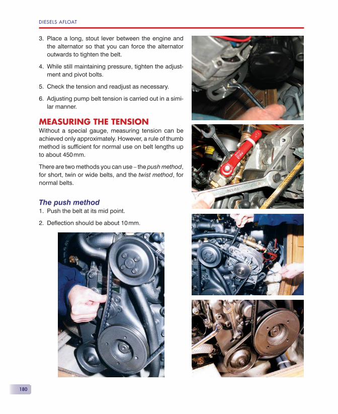
DIESELS AFLOAT
180
Place a long, stout lever between the engine and the alternator so that you can force the alternator outwards to tighten the belt.
While still maintaining pressure, tighten the adjust-ment and pivot bolts.
Check the tension and readjust as necessary.
Adjusting pump belt tension is carried out in a simi-lar manner.
MEASURING THE TENSIONWithout a special gauge, measuring tension can be achieved only approximately. However, a rule of thumb method is suffi cient for normal use on belt lengths up to about 450 mm.
There are two methods you can use — the push method, for short, twin or wide belts, and the twist method, for normal belts.
The push methodPush the belt at its mid point.
Defl ection should be about 10 mm.
3.
4.
5.
6.
1.
2.
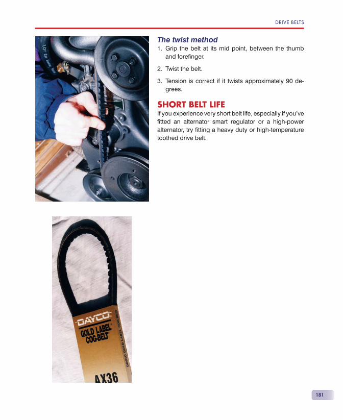
DRIVE BELTS
181
The twist methodGrip the belt at its mid point, between the thumb and forefi nger.
Twist the belt.
Tension is correct if it twists approximately 90 de-grees.
SHORT BELT LIFEIf you experience very short belt life, especially if you’ve fi tted an alternator smart regulator or a high-power alternator, try fi tting a heavy duty or high-temperature toothed drive belt.
1.
2.
3.


183
Strictly speaking, the gear selector should be called the clutch and the throttle should be called the speed control. However, everyone knows
what we mean if we use the usual terms.
When you move the lever from neutral to ahead or astern, you should move it positively to engage the clutches quickly, this prevents clutch slip with its attendant wear. Don’t ‘ease it’ into gear.
When moving the lever from ahead to astern (or vice versa), pause in neutral rather than push the lever right through. I count ‘one and’ as I pause in neutral. This is much kinder to the gearbox. Elec-tronic controls do this automatically — you can’t rush them.
TWIN-LEVER SYSTEMSMechanically, the simplest form of throttle control has a single lever operating a ‘push/pull’ cable at-tached to the speed lever of the engine. Similarly, a separate gear selector lever operates the gearbox
Throttleand Gear Selection
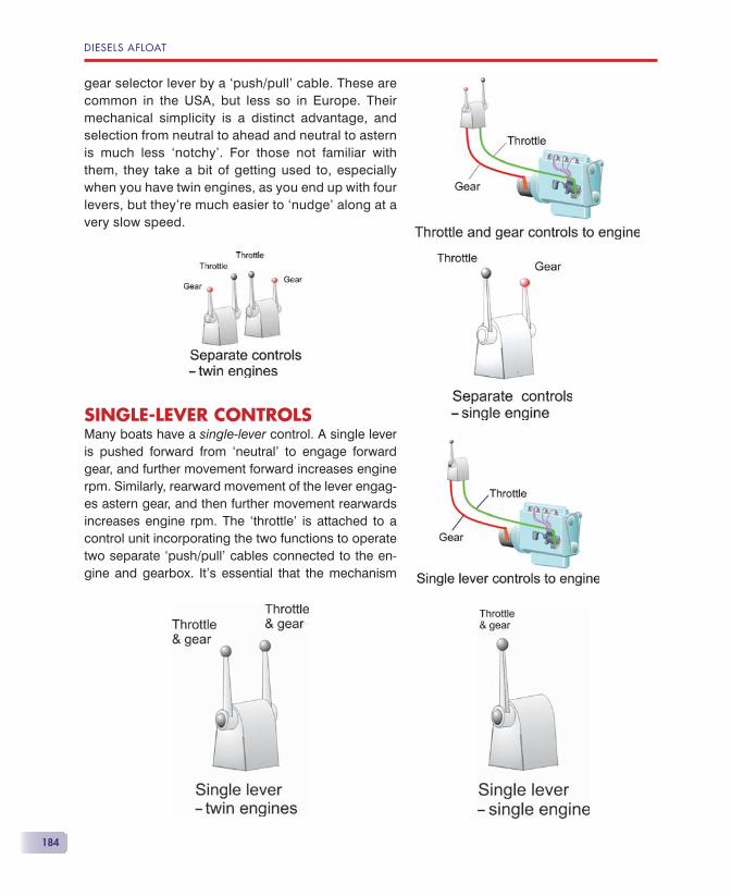
DIESELS AFLOAT
184
gear selector lever by a ‘push/pull’ cable. These are common in the USA, but less so in Europe. Their mechanical simplicity is a distinct advantage, and selection from neutral to ahead and neutral to astern is much less ‘notchy’. For those not familiar with them, they take a bit of getting used to, especially when you have twin engines, as you end up with four levers, but they’re much easier to ‘nudge’ along at a very slow speed.
SINGLE-LEVER CONTROLSMany boats have a single-lever control. A single lever is pushed forward from ‘neutral’ to engage forward gear, and further movement forward increases engine rpm. Similarly, rearward movement of the lever engag-es astern gear, and then further movement rearwards increases engine rpm. The ‘throttle’ is attached to a control unit incorporating the two functions to operate two separate ‘push/pull’ cables connected to the en-gine and gearbox. It’s essential that the mechanism
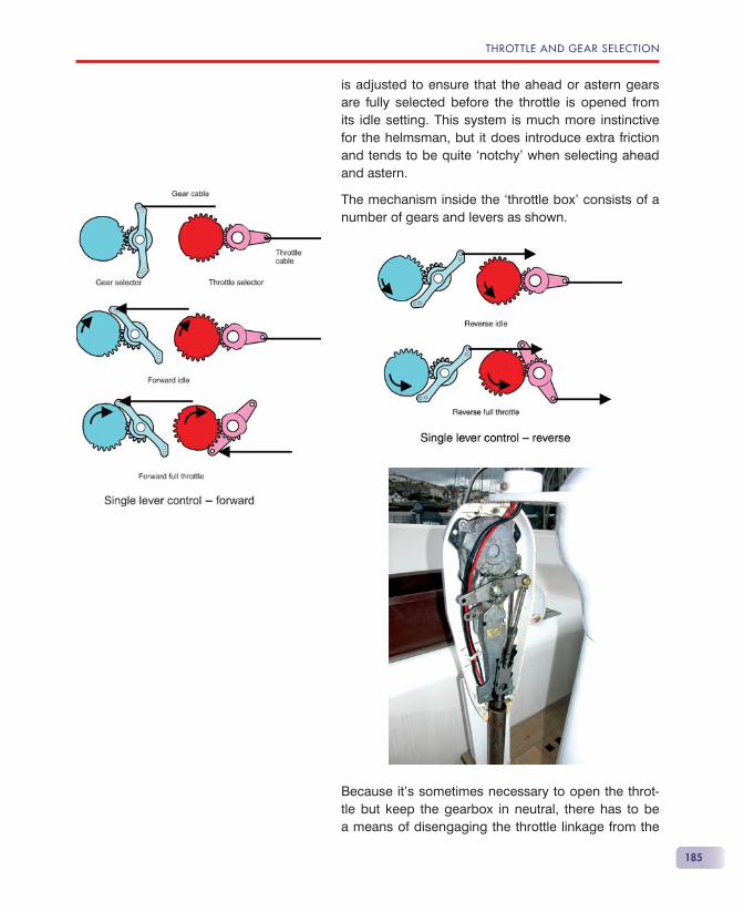
THROTTLE AND GEAR SELECTION
185
is adjusted to ensure that the ahead or astern gears are fully selected before the throttle is opened from its idle setting. This system is much more instinctive for the helmsman, but it does introduce extra friction and tends to be quite ‘notchy’ when selecting ahead and astern.
The mechanism inside the ‘throttle box’ consists of a number of gears and levers as shown.
Because it’s sometimes necessary to open the throt-tle but keep the gearbox in neutral, there has to be a means of disengaging the throttle linkage from the
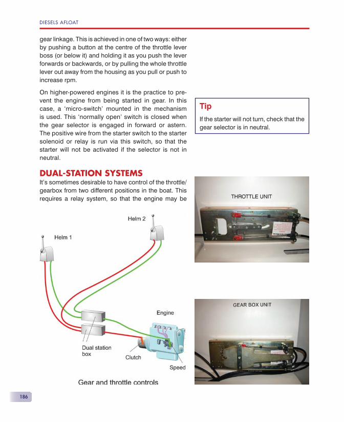
DIESELS AFLOAT
186
gear linkage. This is achieved in one of two ways: either by pushing a button at the centre of the throttle lever boss (or below it) and holding it as you push the lever forwards or backwards, or by pulling the whole throttle lever out away from the housing as you pull or push to increase rpm.
On higher-powered engines it is the practice to pre-vent the engine from being started in gear. In this case, a ‘micro-switch’ mounted in the mechanism is used. This ‘normally open’ switch is closed when the gear selector is engaged in forward or astern. The positive wire from the starter switch to the starter solenoid or relay is run via this switch, so that the starter will not be activated if the selector is not in neutral.
DUAL-STATION SYSTEMSIt’s sometimes desirable to have control of the throttle/gearbox from two different positions in the boat. This requires a relay system, so that the engine may be
Tip
If the starter will not turn, check that the gear selector is in neutral.
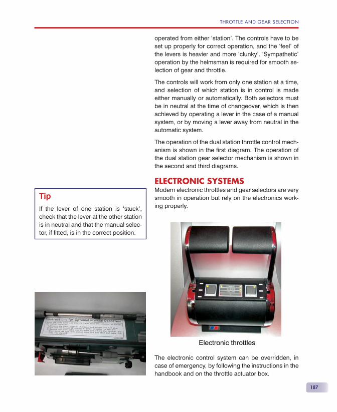
THROTTLE AND GEAR SELECTION
187
operated from either ‘station’. The controls have to be set up properly for correct operation, and the ‘feel’ of the levers is heavier and more ‘clunky’. ‘Sympathetic’ operation by the helmsman is required for smooth se-lection of gear and throttle.
The controls will work from only one station at a time, and selection of which station is in control is made either manually or automatically. Both selectors must be in neutral at the time of changeover, which is then achieved by operating a lever in the case of a manual system, or by moving a lever away from neutral in the automatic system.
The operation of the dual station throttle control mech-anism is shown in the fi rst diagram. The operation of the dual station gear selector mechanism is shown in the second and third diagrams.
ELECTRONIC SYSTEMSModern electronic throttles and gear selectors are very smooth in operation but rely on the electronics work-ing properly.
The electronic control system can be overridden, in case of emergency, by following the instructions in the handbook and on the throttle actuator box.
Tip
If the lever of one station is ‘stuck’, check that the lever at the other station is in neutral and that the manual selec-tor, if fi tted, is in the correct position.
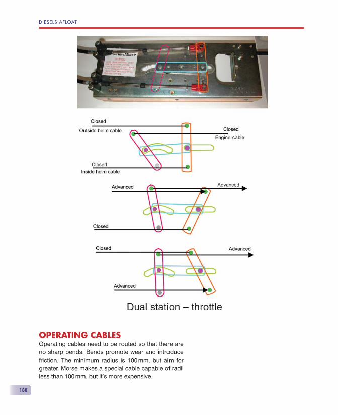
DIESELS AFLOAT
188
OPERATING CABLESOperating cables need to be routed so that there are no sharp bends. Bends promote wear and introduce friction. The minimum radius is 100 mm, but aim for greater. Morse makes a special cable capable of radii less than 100 mm, but it’s more expensive.
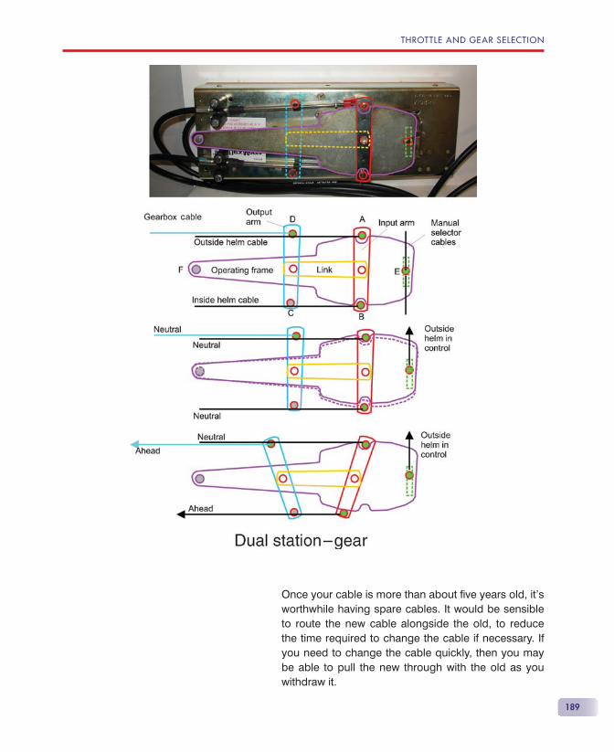
THROTTLE AND GEAR SELECTION
189
Once your cable is more than about fi ve years old, it’s worthwhile having spare cables. It would be sensible to route the new cable alongside the old, to reduce the time required to change the cable if necessary. If you need to change the cable quickly, then you may be able to pull the new through with the old as you withdraw it.
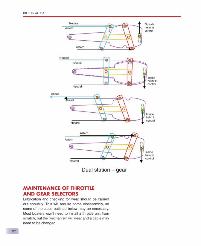
DIESELS AFLOAT
190
MAINTENANCE OF THROTTLEAND GEAR SELECTORSLubrication and checking for wear should be carried out annually. This will require some disassembly, so some of the steps outlined below may be necessary. Most boaters won’t need to install a throttle unit from scratch, but the mechanism will wear and a cable may need to be changed.
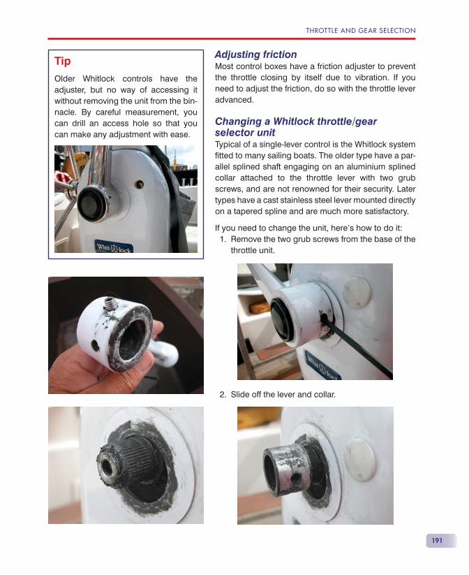
THROTTLE AND GEAR SELECTION
191
Adjusting frictionMost control boxes have a friction adjuster to prevent the throttle closing by itself due to vibration. If you need to adjust the friction, do so with the throttle lever advanced.
Changing a Whitlock throttle/gear selector unitTypical of a single-lever control is the Whitlock system fi tted to many sailing boats. The older type have a par-allel splined shaft engaging on an aluminium splined collar attached to the throttle lever with two grub screws, and are not renowned for their security. Later types have a cast stainless steel lever mounted directly on a tapered spline and are much more satisfactory.
If you need to change the unit, here’s how to do it:Remove the two grub screws from the base of the throttle unit.
Slide off the lever and collar.
1.
2.
Tip
Older Whitlock controls have the adjuster, but no way of accessing it without removing the unit from the bin-nacle. By careful measurement, you can drill an access hole so that you can make any adjustment with ease.
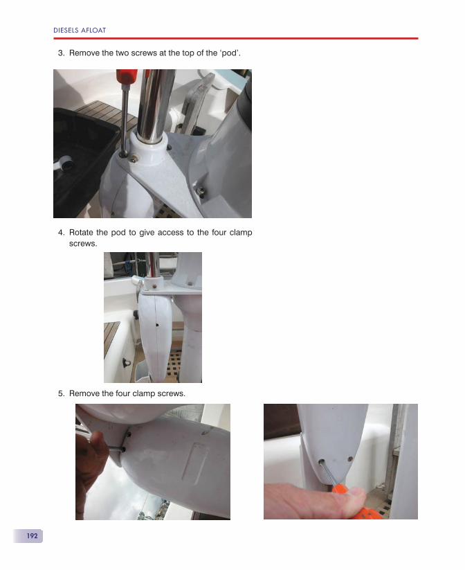
DIESELS AFLOAT
192
Remove the two screws at the top of the ‘pod’.
Rotate the pod to give access to the four clamp screws.
Remove the four clamp screws.
3.
4.
5.
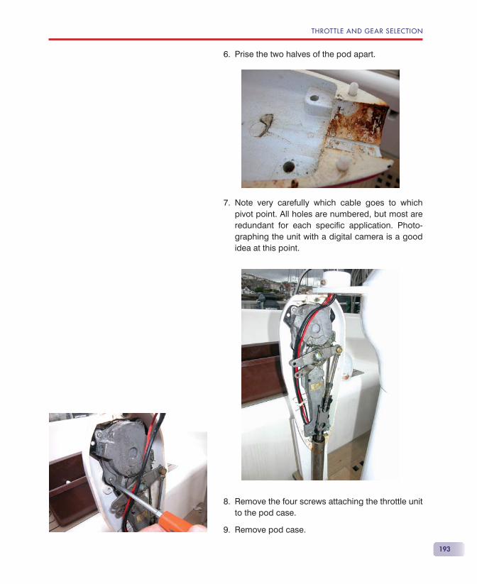
THROTTLE AND GEAR SELECTION
193
Prise the two halves of the pod apart.
Note very carefully which cable goes to which pivot point. All holes are numbered, but most are redundant for each specifi c application. Photo-graphing the unit with a digital camera is a good idea at this point.
Remove the four screws attaching the throttle unit to the pod case.
Remove pod case.
6.
7.
8.
9.
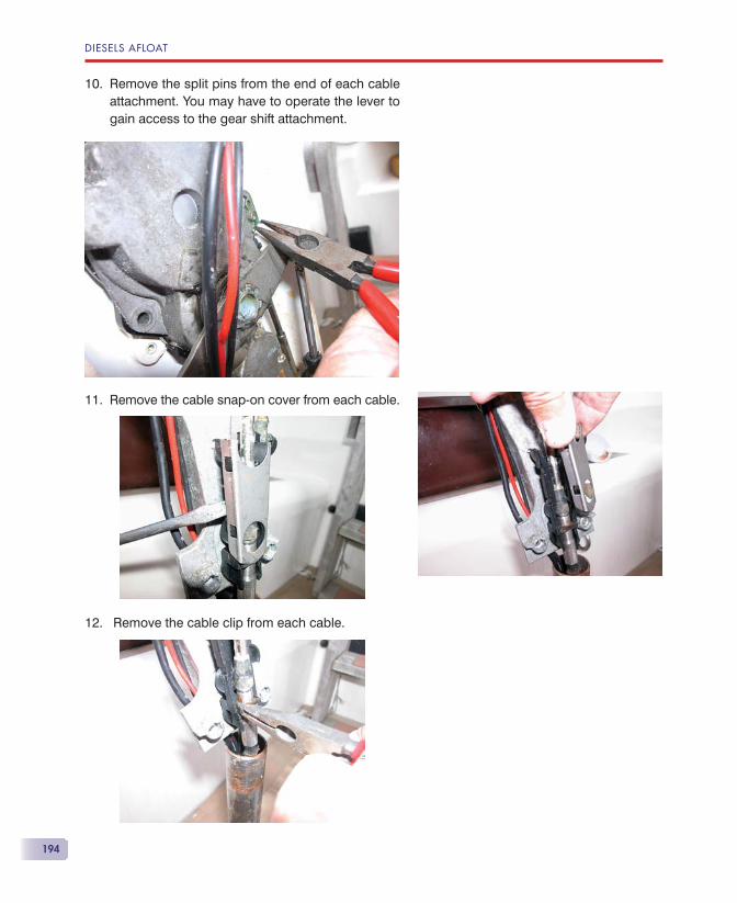
DIESELS AFLOAT
194
Remove the split pins from the end of each cable attachment. You may have to operate the lever to gain access to the gear shift attachment.
Remove the cable snap-on cover from each cable.
Remove the cable clip from each cable.
10.
11.
12.
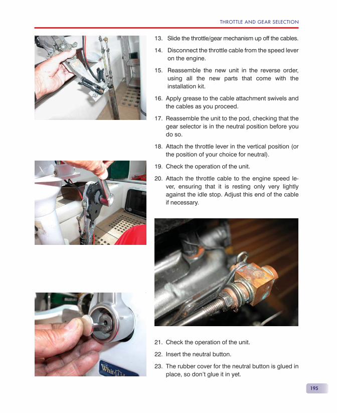
THROTTLE AND GEAR SELECTION
195
Slide the throttle/gear mechanism up off the cables.
Disconnect the throttle cable from the speed lever on the engine.
Reassemble the new unit in the reverse order, using all the new parts that come with the installation kit.
Apply grease to the cable attachment swivels and the cables as you proceed.
Reassemble the unit to the pod, checking that the gear selector is in the neutral position before you do so.
Attach the throttle lever in the vertical position (or the position of your choice for neutral).
Check the operation of the unit.
Attach the throttle cable to the engine speed le-ver, ensuring that it is resting only very lightly against the idle stop. Adjust this end of the cable if necessary.
Check the operation of the unit.
Insert the neutral button.
The rubber cover for the neutral button is glued in place, so don’t glue it in yet.
13.
14.
15.
16.
17.
18.
19.
20.
21.
22.
23.
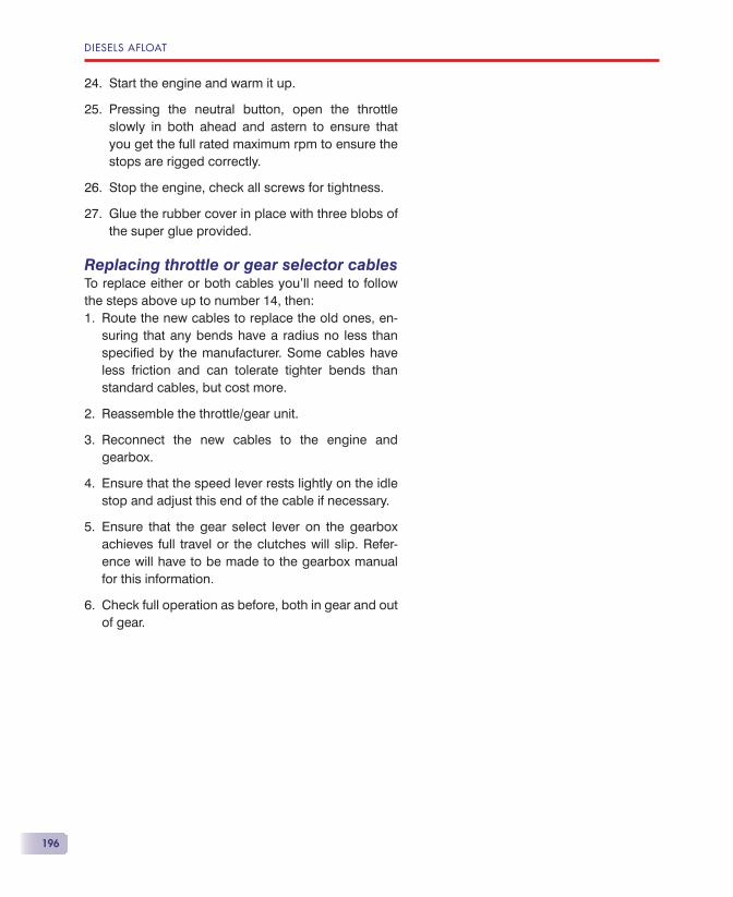
DIESELS AFLOAT
196
Start the engine and warm it up.
Pressing the neutral button, open the throttle slowly in both ahead and astern to ensure that you get the full rated maximum rpm to ensure the stops are rigged correctly.
Stop the engine, check all screws for tightness.
Glue the rubber cover in place with three blobs of the super glue provided.
Replacing throttle or gear selector cablesTo replace either or both cables you’ll need to follow the steps above up to number 14, then:
Route the new cables to replace the old ones, en-suring that any bends have a radius no less than specifi ed by the manufacturer. Some cables have less friction and can tolerate tighter bends than standard cables, but cost more.
Reassemble the throttle/gear unit.
Reconnect the new cables to the engine and gearbox.
Ensure that the speed lever rests lightly on the idle stop and adjust this end of the cable if necessary.
Ensure that the gear select lever on the gearbox achieves full travel or the clutches will slip. Refer-ence will have to be made to the gearbox manual for this information.
Check full operation as before, both in gear and out of gear.
24.
25.
26.
27.
1.
2.
3.
4.
5.
6.

197
Just like modern cars and trucks, control of ex-haust emissions is becoming a prime factor in modern marine diesel engine design. A major
feature in the control of emissions is electronic engine management, and the latest high-power marine die-sels are now equipped with it. As time goes on, elec-tronic management will be fi tted to smaller engines as well. The electronic engine management box will be found on the side of the engine.
Again, just like your car, reliability is pretty good, but problems can arise out of the blue, and solving them can be time-consuming and inconclusive if they are intermittent.
WHAT IS ELECTRONIC ENGINE MANAGEMENT?Electronic engine management controls every step of the operation of the engine and gearbox.
• When you are ready to start the engine, you turn the ‘ignition’ key to ON. This switches on the electronic
ElectronicEngineManagement
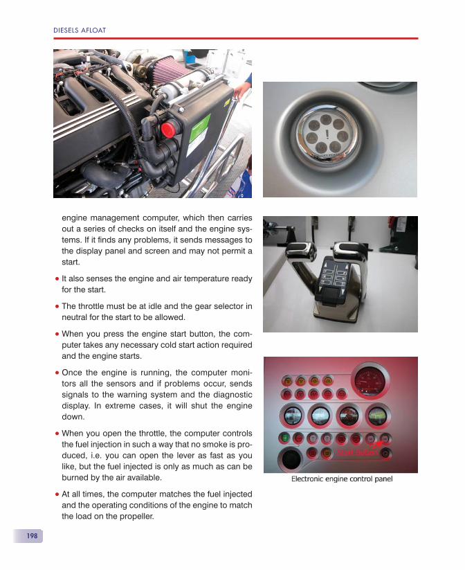
DIESELS AFLOAT
198
engine management computer, which then carries out a series of checks on itself and the engine sys-tems. If it fi nds any problems, it sends messages to the display panel and screen and may not permit a start.
• It also senses the engine and air temperature ready for the start.
• The throttle must be at idle and the gear selector in neutral for the start to be allowed.
• When you press the engine start button, the com-puter takes any necessary cold start action required and the engine starts.
• Once the engine is running, the computer moni-tors all the sensors and if problems occur, sends signals to the warning system and the diagnostic display. In extreme cases, it will shut the engine down.
• When you open the throttle, the computer controls the fuel injection in such a way that no smoke is pro-duced, i.e. you can open the lever as fast as you like, but the fuel injected is only as much as can be burned by the air available.
• At all times, the computer matches the fuel injected and the operating conditions of the engine to match the load on the propeller.
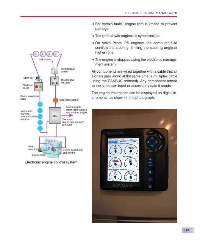
ELECTRONIC ENGINE MANAGEMENT
199
• For certain faults, engine rpm is limited to prevent damage.
• The rpm of twin engines is synchronised.
• On Volvo Penta IPS engines, the computer also controls the steering, limiting the steering angle at higher rpm.
• The engine is stopped using the electronic manage-ment system.
All components are wired together with a cable that all signals pass along at the same time (a multiplex cable using the CANBUS protocol). Any component added to the cable can input or access any data it needs.
The engine information can be displayed on digital in-struments, as shown in the photograph.
DIESELS AFLOAT
200
Failure of any part of the system can result in the en-gine either not starting, not stopping or stopping when you don’t want it to; however, like the modern car, as long as all is working properly, operation of the engine requires very little thought.
Because there’s no throttle and gear cables or dual-station boxes, throttle and gear selection is friction free, making low speed control very smooth. Elec-tronic throttle and gear selection can be retro-fi tted to engines without electronic engine management.
On Volvo IPS installations, a joystick control and addi-tional computer can be added to control engine speed, gear selection and steering input, to make very slow speed control ultra precise, so that the boat can be moved sideways from its berth with a single control!
Routine maintenance by an agent for your engine should ensure that at each service, the service history of the engine can be read from the computer via a laptop or PDA, and any pending problems rectifi ed.
TROUBLESHOOTINGWith electronic engine management, troubleshooting becomes both easier and more diffi cult at the same time. Easier because all you have to do is plug a laptop computer or PDA into the diagnostic socket to fi nd out what’s wrong, and more diffi cult because you have to go to a main dealer to fi nd someone with the equipment and the knowledge of how to interpret the information.
Your engine handbook will tell you what the various indications mean and what to do. It would be an excel-lent idea to photocopy the relevant diagnostic pages in the engine handbook and have them readily to hand as an aid to troubleshooting.
As far as the owner is concerned, there is little he can do except read the diagnostic panel, get out the handbook and fi nd out what the indications mean. There are few connections that he can check, except to see if 12 volts is available at the starter motor sole-noid if the engine won’t start.
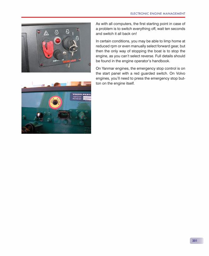
ELECTRONIC ENGINE MANAGEMENT
201
As with all computers, the fi rst starting point in case of a problem is to switch everything off, wait ten seconds and switch it all back on!
In certain conditions, you may be able to limp home at reduced rpm or even manually select forward gear, but then the only way of stopping the boat is to stop the engine, as you can’t select reverse. Full details should be found in the engine operator’s handbook.
On Yanmar engines, the emergency stop control is on the start panel with a red guarded switch. On Volvo engines, you’ll need to press the emergency stop but-ton on the engine itself.


203
INTRODUCTIONPropeller design is a bit of a black art. There are books dealing with the subject that allow you to calculate, rather laboriously, the shape and size of a propeller for a given application. Now there’s computer software to do the job effortlessly. What do they have in common? All the methods are based on trial and error, they use assumptions, and at the end of the day will get you a prop of roughly the correct design that only sea trials will verify. With as much computing power and theory as is available to design aeroplanes, we could get pretty well spot on fi rst time, but in reality, that’s never going to be available to the leisure craft industry.
A PROPELLERLook at your propeller and you’ll fi nd stamped on the hub something like 17 � 11 LH. The fi rst number (17) is the diameter of the propeller in inches. The second number(11) is the pitch of the prop, again in inches. This represents the angle of the blade to the propeller shaft centreline, so why is it in inches and not in de-grees? Rotate the propeller on its shaft one turn and it will wind its way forward by the amount of pitch, in this case 11 inches. Just like a screw, after which the prop is named, being driven into a piece of wood. The let-ters LH tell us that it is has left-hand rotation. Propeller
Propellers
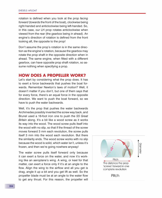
DIESELS AFLOAT
204
rotation is defi ned when you look at the prop facing forward (towards the front of the boat), clockwise being right-handed and anticlockwise being left-handed. So, in this case, our LH prop rotates anticlockwise when viewed from the rear (the gearbox being in ahead). An engine’s direction of rotation is defi ned from the front looking aft, the opposite to the prop!
Don’t assume the prop’s rotation is in the same direc-tion as the engine’s rotation, because the gearbox may rotate the prop shaft in the opposite direction when in ahead. The same engine, when fi tted with a different gearbox, can have opposite prop shaft rotation, so as-sume nothing when specifying a prop.
HOW DOES A PROPELLER WORK?Let’s start by considering what the prop does. It has to exert a force backwards that pushes the boat for-wards. Remember Newton’s laws of motion? Well, it doesn’t matter if you don’t, but one of them says that for every force, there’s an equal force in the opposite direction. We want to push the boat forward, so we have to push the water backwards.
Well, it’s the prop that pushes the water backwards Archimedes possibly invented the screw way back, and Brunel used a 16-foot iron one to push the SS Great Britain along. It’s a bit like a wood screw as it works its way into the wood. The wood screw pulls itself into the wood with no slip, so that if the thread of the screw moves forward 3 mm each revolution, the screw pulls itself 3 mm into the wood each revolution. But there the similarity ends. The wood screw works with no slip because the wood is solid, which water isn’t, unless it’s frozen, and then we’re going nowhere anyway!
The water screw pulls itself forward only because it can exert a force on the water, and now it’s work-ing like an aeroplane’s wing. A wing, or keel for that matter, can exert a force only if it’s at an angle to the fl ow. Align the wing to the airfl ow and all you get is drag, angle it up a bit and you get lift as well. So the propeller blade must be at an angle to the water fl ow to get any thrust. For this reason, the propeller will
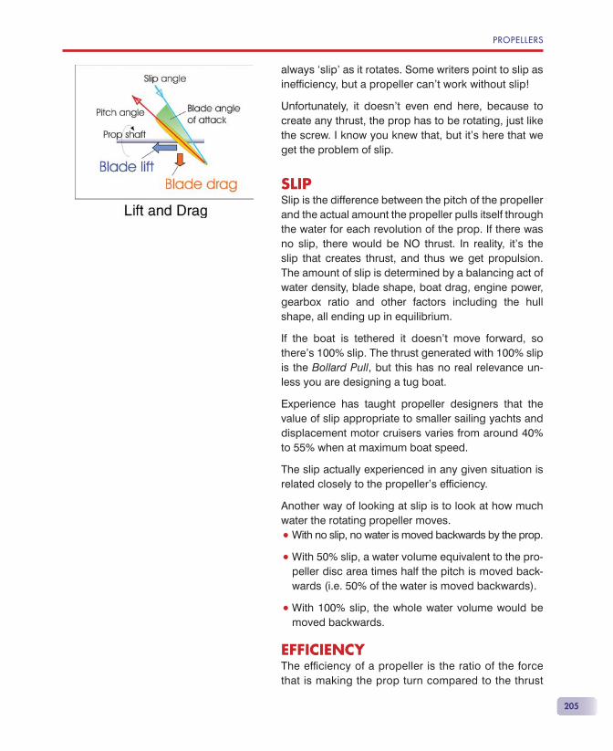
PROPELLERS
205
always ‘slip’ as it rotates. Some writers point to slip as ineffi ciency, but a propeller can’t work without slip!
Unfortunately, it doesn’t even end here, because to create any thrust, the prop has to be rotating, just like the screw. I know you knew that, but it’s here that we get the problem of slip.
SLIPSlip is the difference between the pitch of the propeller and the actual amount the propeller pulls itself through the water for each revolution of the prop. If there was no slip, there would be NO thrust. In reality, it’s the slip that creates thrust, and thus we get propulsion. The amount of slip is determined by a balancing act of water density, blade shape, boat drag, engine power, gearbox ratio and other factors including the hull shape, all ending up in equilibrium.
If the boat is tethered it doesn’t move forward, so there’s 100% slip. The thrust generated with 100% slip is the Bollard Pull, but this has no real relevance un-less you are designing a tug boat.
Experience has taught propeller designers that the value of slip appropriate to smaller sailing yachts and displacement motor cruisers varies from around 40% to 55% when at maximum boat speed.
The slip actually experienced in any given situation is related closely to the propeller’s effi ciency.
Another way of looking at slip is to look at how much water the rotating propeller moves.
• With no slip, no water is moved backwards by the prop.
• With 50% slip, a water volume equivalent to the pro-peller disc area times half the pitch is moved back-wards (i.e. 50% of the water is moved backwards).
• With 100% slip, the whole water volume would be moved backwards.
EFFICIENCYThe effi ciency of a propeller is the ratio of the force that is making the prop turn compared to the thrust
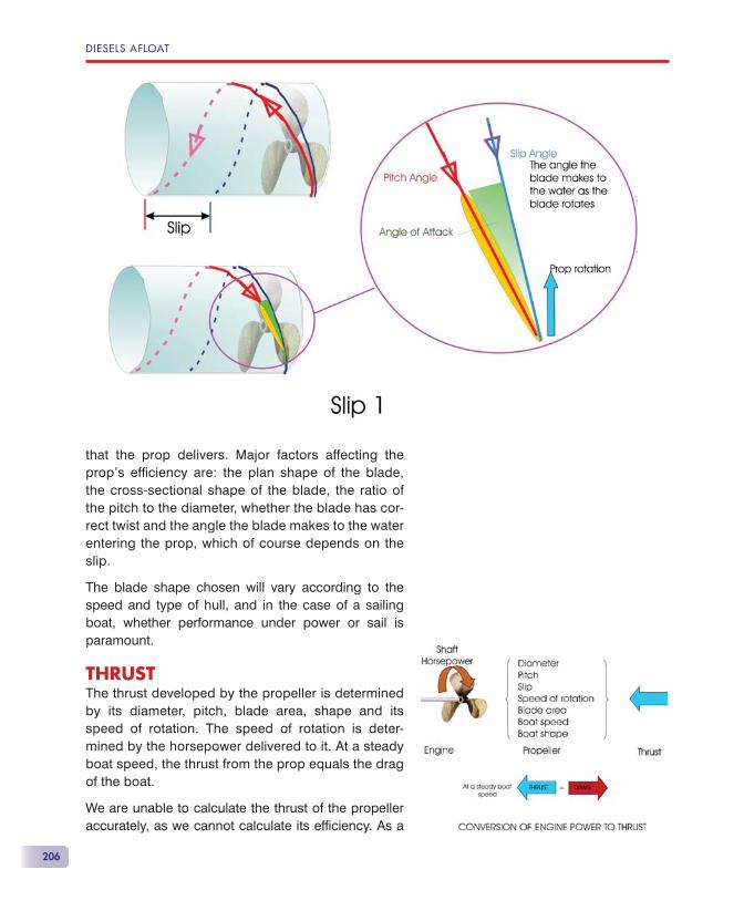
DIESELS AFLOAT
206
that the prop delivers. Major factors affecting the prop’s effi ciency are: the plan shape of the blade, the cross-sectional shape of the blade, the ratio of the pitch to the diameter, whether the blade has cor-rect twist and the angle the blade makes to the water entering the prop, which of course depends on the slip.
The blade shape chosen will vary according to the speed and type of hull, and in the case of a sailing boat, whether performance under power or sail is paramount.
THRUSTThe thrust developed by the propeller is determined by its diameter, pitch, blade area, shape and its speed of rotation. The speed of rotation is deter-mined by the horsepower delivered to it. At a steady boat speed, the thrust from the prop equals the drag of the boat.
We are unable to calculate the thrust of the propeller accurately, as we cannot calculate its effi ciency. As a
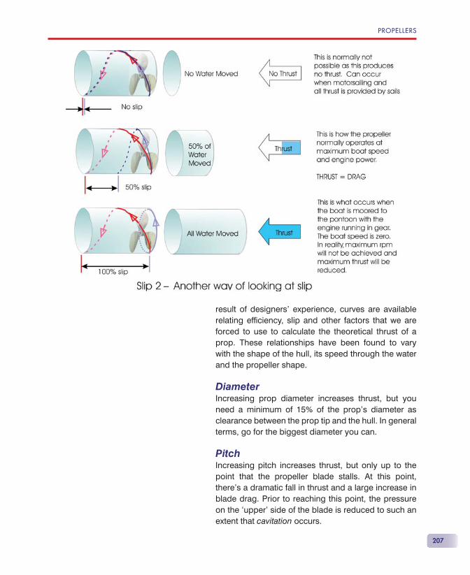
PROPELLERS
207
result of designers’ experience, curves are available relating effi ciency, slip and other factors that we are forced to use to calculate the theoretical thrust of a prop. These relationships have been found to vary with the shape of the hull, its speed through the water and the propeller shape.
DiameterIncreasing prop diameter increases thrust, but you need a minimum of 15% of the prop’s diameter as clearance between the prop tip and the hull. In general terms, go for the biggest diameter you can.
PitchIncreasing pitch increases thrust, but only up to the point that the propeller blade stalls. At this point, there’s a dramatic fall in thrust and a large increase in blade drag. Prior to reaching this point, the pressure on the ‘upper’ side of the blade is reduced to such an extent that cavitation occurs.
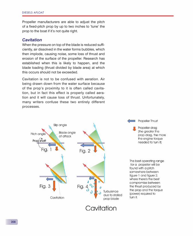
DIESELS AFLOAT
208
Propeller manufacturers are able to adjust the pitch of a fi xed-pitch prop by up to two inches to ‘tune’ the prop to the boat if it’s not quite right.
CavitationWhen the pressure on top of the blade is reduced suffi -ciently, air dissolved in the water forms bubbles, which then implode, causing noise, some loss of thrust and erosion of the surface of the propeller. Research has established when this is likely to happen, and the blade loading (thrust divided by blade area) at which this occurs should not be exceeded.
Cavitation is not to be confused with aeration. Air being drawn down from the water surface because of the prop’s proximity to it is often called cavita-tion, but in fact this effect is properly called aera-tion and it will cause loss of thrust. Unfortunately, many writers confuse these two entirely different processes.

PROPELLERS
209
Blade areaUp to the point at which blade loading makes cavita-tion likely, the blade area is not a big factor, as reduced blade area is made up by increased pitch. If the prop is working close to the cavitation point, extra blade area will reduce the likelihood of cavitation.
Blade area is normally considered as the blade area ratio: the area of the blades divided by the area of the blade diameter circle.
So, if the prop is working well within its limits, such as when cruising, a two-bladed prop (of correct pitch) will produce a thrust similar to a three-bladed one. In fact, because each blade has more room, it is likely to be more efficient than a three-bladed prop and deliver more thrust. However, when the two-bladed prop is running under adverse condi-tions, such as rough weather, or under maximum acceleration, the three-bladed prop will then de-liver more thrust, because its blade loading will be lower.
This can be seen in the table, where the thrust and maximum speeds of all three types of 17 inch diame-ter props are very similar, although the performance of the two-blade folding prop (which has narrow blades of small area) has started to fall due to overloading. However, only at lower blade loadings is there any margin of performance to allow for adverse condi-tions. The margin of the folding two-blader would be improved by changing the gear ratio so that it turns more slowly and then increasing its diameter to 18 inches. The table shows some prop calculations for a twenty horsepower engine driving a two-ton boat at maximum speed.
Blade twistThe speed at which the propeller blade meets the wa-ter varies along its length, because the tip speed of ro-tation is much faster than at the root. In order that the blade’s angle of attack is the same all the way along, the propeller blade must be twisted.
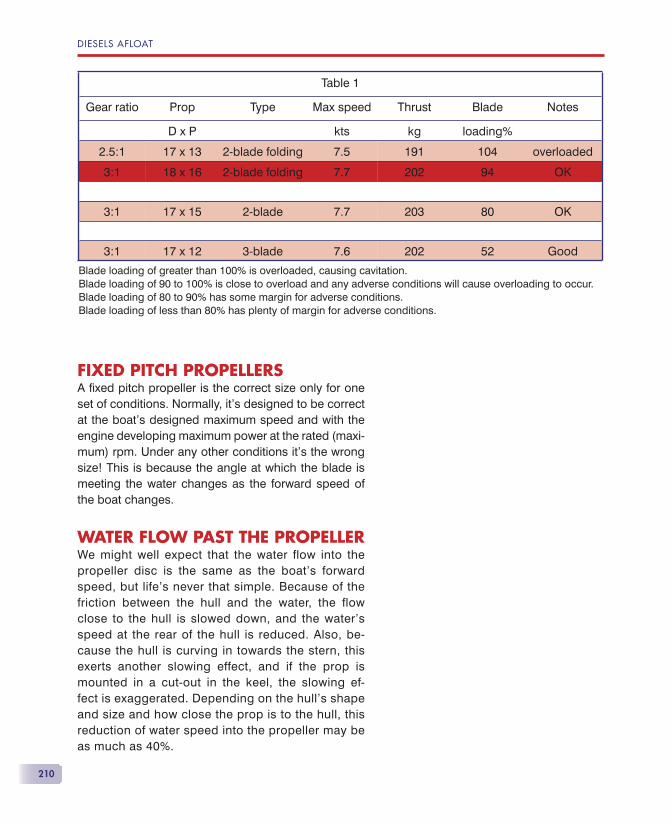
DIESELS AFLOAT
210
FIXED PITCH PROPELLERSA fi xed pitch propeller is the correct size only for one set of conditions. Normally, it’s designed to be correct at the boat’s designed maximum speed and with the engine developing maximum power at the rated (maxi-mum) rpm. Under any other conditions it’s the wrong size! This is because the angle at which the blade is meeting the water changes as the forward speed of the boat changes.
WATER FLOW PAST THE PROPELLERWe might well expect that the water flow into the propeller disc is the same as the boat’s forward speed, but life’s never that simple. Because of the friction between the hull and the water, the flow close to the hull is slowed down, and the water’s speed at the rear of the hull is reduced. Also, be-cause the hull is curving in towards the stern, this exerts another slowing effect, and if the prop is mounted in a cut-out in the keel, the slowing ef-fect is exaggerated. Depending on the hull’s shape and size and how close the prop is to the hull, this reduction of water speed into the propeller may be as much as 40%.
Table 1
Gear ratio Prop Type Max speed Thrust Blade Notes
D x P kts kg loading%
2.5:1 17 x 13 2-blade folding 7.5 191 104 overloaded
3:1 18 x 16 2-blade folding 7.7 202 94 OK
3:1 17 x 15 2-blade 7.7 203 80 OK
3:1 17 x 12 3-blade 7.6 202 52 Good
Blade loading of greater than 100% is overloaded, causing cavitation.Blade loading of 90 to 100% is close to overload and any adverse conditions will cause overloading to occur.Blade loading of 80 to 90% has some margin for adverse conditions.Blade loading of less than 80% has plenty of margin for adverse conditions.
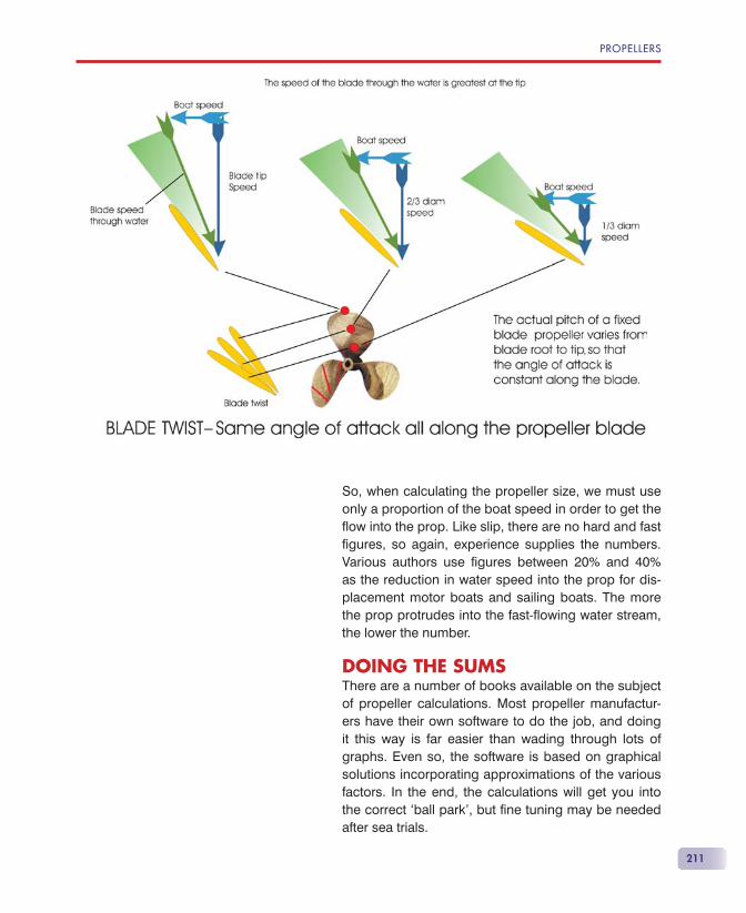
PROPELLERS
211
So, when calculating the propeller size, we must use only a proportion of the boat speed in order to get the fl ow into the prop. Like slip, there are no hard and fast fi gures, so again, experience supplies the numbers. Various authors use fi gures between 20% and 40% as the reduction in water speed into the prop for dis-placement motor boats and sailing boats. The more the prop protrudes into the fast-fl owing water stream, the lower the number.
DOING THE SUMSThere are a number of books available on the subject of propeller calculations. Most propeller manufactur-ers have their own software to do the job, and doing it this way is far easier than wading through lots of graphs. Even so, the software is based on graphical solutions incorporating approximations of the various factors. In the end, the calculations will get you into the correct ‘ball park’, but fi ne tuning may be needed after sea trials.
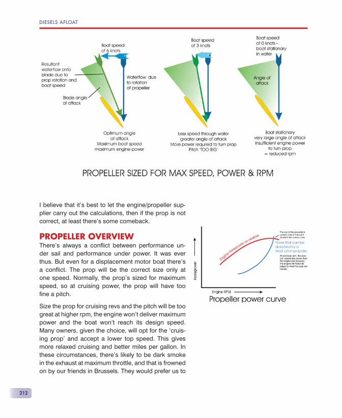
DIESELS AFLOAT
212
I believe that it’s best to let the engine/propeller sup-plier carry out the calculations, then if the prop is not correct, at least there’s some comeback.
PROPELLER OVERVIEWThere’s always a confl ict between performance un-der sail and performance under power. It was ever thus. But even for a displacement motor boat there’s a confl ict. The prop will be the correct size only at one speed. Normally, the prop’s sized for maximum speed, so at cruising power, the prop will have too fi ne a pitch.
Size the prop for cruising revs and the pitch will be too great at higher rpm, the engine won’t deliver maximum power and the boat won’t reach its design speed. Many owners, given the choice, will opt for the ‘cruis-ing prop’ and accept a lower top speed. This gives more relaxed cruising and better miles per gallon. In these circumstances, there’s likely to be dark smoke in the exhaust at maximum throttle, and that is frowned on by our friends in Brussels. They would prefer us to
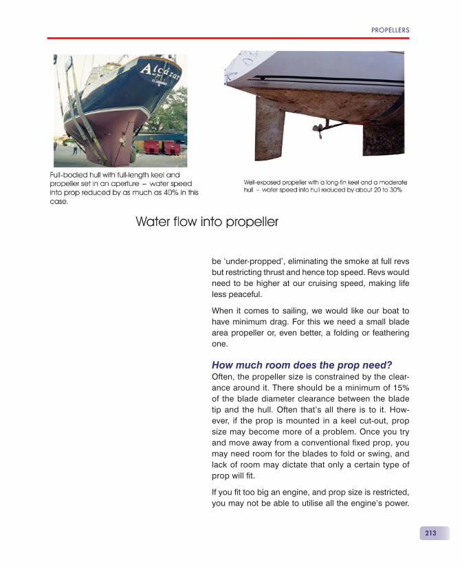
PROPELLERS
213
be ‘under-propped’, eliminating the smoke at full revs but restricting thrust and hence top speed. Revs would need to be higher at our cruising speed, making life less peaceful.
When it comes to sailing, we would like our boat to have minimum drag. For this we need a small blade area propeller or, even better, a folding or feathering one.
How much room does the prop need?Often, the propeller size is constrained by the clear-ance around it. There should be a minimum of 15% of the blade diameter clearance between the blade tip and the hull. Often that’s all there is to it. How-ever, if the prop is mounted in a keel cut-out, prop size may become more of a problem. Once you try and move away from a conventional fi xed prop, you may need room for the blades to fold or swing, and lack of room may dictate that only a certain type of prop will fi t.
If you fi t too big an engine, and prop size is restricted, you may not be able to utilise all the engine’s power.
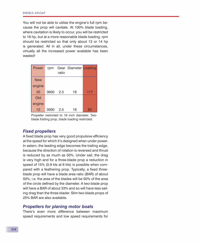
DIESELS AFLOAT
214
You will not be able to utilise the engine’s full rpm be-cause the prop will cavitate. At 100% blade loading, where cavitation is likely to occur, you will be restricted to 16 hp, but at a more reasonable blade loading, rpm should be restricted so that only about 13 or 14 hp is generated. All in all, under these circumstances, virtually all the increased power available has been wasted!
Fixed propellersA fi xed blade prop has very good propulsive effi ciency at the speed for which it’s designed when under power. In astern, the leading edge becomes the trailing edge, because the direction of rotation is reversed and thrust is reduced by as much as 50%. Under sail, the drag is very high and for a three-blade prop a reduction in speed of 15% (0.9 kts at 6 kts) is possible when com-pared with a feathering prop. Typically, a fi xed three-blade prop will have a blade area ratio (BAR) of about 50%, i.e. the area of the blades will be 50% of the area of the circle defi ned by the diameter. A two-blade prop will have a BAR of about 33% and so will have less sail-ing drag than the three-blader. Slim two-blade props of 25% BAR are also available.
Propellers for planing motor boatsThere’s even more difference between maximum speed requirements and low speed requirements for
Power rpm Gear ratio
Diameter Loading
New
engine
20 3600 2.5 16 117
Old
engine
12 3000 2.5 16 83
Propeller restricted to 16 inch diameter. Two-blade folding prop, blade loading restricted.
PROPELLERS
215
high-speed craft. Obviously, the propeller will be de-signed for maximum speed and the prop will be inef-fi cient at low speed. A particular problem occurs at the speed at which the boat just starts to plane. A lot of thrust is needed to get over the ‘hump’, but the pitch is completely wrong for this speed. Specialist high-speed props have been developed, and one gearbox manu-facturer has a two-speed gearbox so that you have a gear ratio matched for low-speed work up to just above the ‘hump’, and a higher gear for high-speed cruising. If the engine power available is marginal, an incorrect prop can even prevent the boat getting on the plane.
Folding propellersFolding props have considerably less drag than fixed props when sailing, but some tend to slam or jerk as they open and there’s some lag as the throttle is opened. They tend to be pretty poor in astern, because they don’t open fully, and they may also have less than the optimum amount of twist, and hence they’re not so efficient. Some are more complex than others and this is reflected in their price.
• Folding two-blade props have a small blade area (around 25% BAR), so end up with high blade load-ing and a risk of cavitation.
• Folding three-blade props have more blade area, so run at a satisfactory blade loading but still have little twist.
• They need room behind them to allow the blades to fold backwards.
Feathering propellersWith the engine switched off, the blades of feather-ing propellers turn at their roots instead of folding, so that the blades are edge on to the water flow past the prop and have the lowest sailing drag of all propellers.
DIESELS AFLOAT
216
They come in two- and three-blade forms and have a greater blade area (similar to a fi xed prop) than their folding brethren, so have a reasonable blade load-ing and are less susceptible to cavitation. However, they have no twist at all, so lose out on propulsive effi ciency, but are much better than a fi xed prop in astern, as the leading edge of the blade remains the leading edge — the blade fl ips round when going backwards.
These need room for the blades to swivel, but don’t need a lot more room than a conventional prop.
Self-pitching propellersTo overcome the problem of there being only one boat speed/engine speed combination that is correct for the prop, we could arrange for the propeller to have variable pitch, and then we could have the best of all worlds. This is done on many propeller-driven aircraft, but it’s costly and needs two levers — a power lever and a pitch lever.
Brunton Propellers have developed their Autoprop, which cleverly balances centrifugal force, water load on the blade and engine power using swivel-ling blades, to give a continuously variable pitch matched to the load. This means that over quite a large boat speed/engine power band, the prop is always the ‘right size’, with the claimed advantages of better fuel effi ciency, more thrust and lower cruis-ing rpm. It also works well when motoring in rough weather.
Sailing drag is low, only a little more than a feather-ing prop, and, like the feathering prop, the blades flip round in astern, so giving good reverse thrust. Additionally, the blades are twisted properly to maintain a constant angle of attack. Annual main-tenance is required to lubricate the ball races, and it would be as well to invest in the special prop puller to avoid damage if you have to remove the prop.
They need room both in front of and behind the prop to allow the blades to swing.

PROPELLERS
217
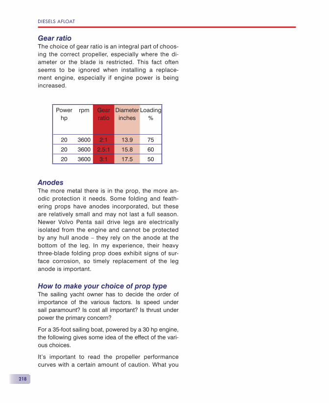
DIESELS AFLOAT
218
Gear ratioThe choice of gear ratio is an integral part of choos-ing the correct propeller, especially where the di-ameter or the blade is restricted. This fact often seems to be ignored when installing a replace-ment engine, especially if engine power is being increased.
AnodesThe more metal there is in the prop, the more an-odic protection it needs. Some folding and feath-ering props have anodes incorporated, but these are relatively small and may not last a full season. Newer Volvo Penta sail drive legs are electrically isolated from the engine and cannot be protected by any hull anode — they rely on the anode at the bottom of the leg. In my experience, their heavy three-blade folding prop does exhibit signs of sur-face corrosion, so timely replacement of the leg anode is important.
How to make your choice of prop typeThe sailing yacht owner has to decide the order of importance of the various factors. Is speed under sail paramount? Is cost all important? Is thrust under power the primary concern?
For a 35-foot sailing boat, powered by a 30 hp engine, the following gives some idea of the effect of the vari-ous choices.
It’s important to read the propeller performance curves with a certain amount of caution. What you
Powerhp
rpm Gear ratio
Diameterinches
Loading%
20 3600 2:1 13.9 75
20 3600 2.5:1 15.8 60
20 3600 3:1 17.5 50
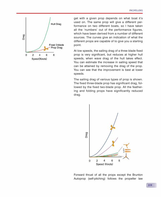
PROPELLERS
219
get with a given prop depends on what boat it’s used on. The same prop will give a different per-formance on two different boats, so I have taken all the ‘numbers’ out of the performance figures, which have been derived from a number of different sources. The curves give an indication of what the different props are capable of to give you a starting point.
At low speeds, the sailing drag of a three blade fi xed prop is very signifi cant, but reduces at higher hull speeds, when wave drag of the hull takes effect. You can estimate the increase in sailing speed that can be attained by removing the drag of the prop. You can see that the improvement is best at lower speeds.
The sailing drag of various types of prop is shown. The fixed three-blade prop has significant drag, fol-lowed by the fixed two-blade prop. All the feather-ing and folding props have significantly reduced drag.
Forward thrust of all the props except the Brunton Autoprop (self-pitching) follows the propeller law
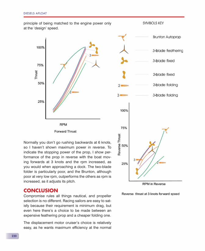
DIESELS AFLOAT
220
principle of being matched to the engine power only at the ‘design’ speed.
Normally you don’t go rushing backwards at 6 knots, so I haven’t shown maximum power in reverse. To indicate the stopping power of the prop, I show per-formance of the prop in reverse with the boat mov-ing forwards at 3 knots and the rpm increased, as you would when approaching a dock. The two-blade folder is particularly poor, and the Brunton, although poor at very low rpm, outperforms the others as rpm is increased, as it adjusts its pitch.
CONCLUSIONCompromise rules all things nautical, and propeller selection is no different. Racing sailors are easy to sat-isfy because their requirement is minimum drag, but even here there’s a choice to be made between an expensive feathering prop and a cheaper folding one.
The displacement motor cruiser’s choice is relatively easy, as he wants maximum effi ciency at the normal
PROPELLERS
221
cruising speed. A fi xed pitch three-bladed prop will be the normal choice.
It’s the cruising yachtsman who has the most diffi cult choice. My experience of long summer cruises over the last few years shows that I spend probably 50% of my time under power, because we tend to day-sail between ports and 12 hours is long enough. We may not be completely typical, but on passage below about 2 knots, on goes the engine. Also, if the going is heavy and we are going to windward, we often mo-tor-sail at about 20 degrees off the wind, and propeller thrust is important. When the boat was new, we opted for a three-blade fi xed prop. The downside of this is that we lose at least half a knot when sailing at 5½ knots, and big waves still reduce our speed, despite the three blades.
I now use a Brunton Autoprop to give better speed both under sail and under power in heavy weather and reduced cruising rpm with no loss of speed. The downside of this is the cost, but I’m delighted with its performance. It has eliminated prop-walk as well.
If you want to have a look at a book of propeller theory that is not too diffi cult to understand, then have a look at: Propeller Handbook by Dave Gerr (ISBN 0-7136-5751-0, published by Nautical Books).


223
Preventing faults, especially at sea, is very much in the yachtsman’s own hands. How can you prevent your engine breaking down?
You can prevent most faults occurring by:
• carrying out regular routine maintenance;
• carrying out your daily checks;
• reading your engine handbook;
• keeping your engine clean;
• understanding how your engine works;
• listening and looking for early signs of future trouble.
Your boat builder can help prevent faults occurring by:
• making a proper installation;
• making the engine and its service points accessible.
In a way, you have control of what the boat builder does, by not buying a boat with a poor installation or poor accessibility. I’ve been told by prospective buyers that they aren’t interested in engine accessibility, as they will be using an engineer to do the maintenance. If you can’t get at the water pump or take the engine
Prevention of Faults
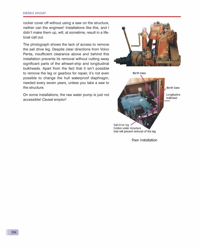
DIESELS AFLOAT
224
rocker cover off without using a saw on the structure, neither can the engineer! Installations like this, and I didn’t make them up, will, at sometime, result in a life-boat call out.
The photograph shows the lack of access to remove the sail drive leg. Despite clear directions from Volvo Penta, insuffi cient clearance above and behind this installation prevents its removal without cutting away signifi cant parts of the athwart-ship and longitudinal bulkheads. Apart from the fact that it isn’t possible to remove the leg or gearbox for repair, it’s not even possible to change the hull waterproof diaphragm, needed every seven years, unless you take a saw to the structure.
On some installations, the raw water pump is just not accessible! Caveat emptor!
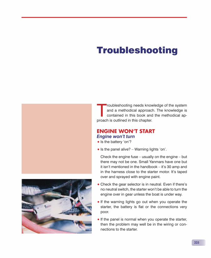
225
Troubleshooting needs knowledge of the system and a methodical approach. The knowledge is contained in this book and the methodical ap-
proach is outlined in this chapter.
ENGINE WON’T STARTEngine won’t turn• Is the battery ‘on’?
• Is the panel alive? — Warning lights ‘on’.
Check the engine fuse — usually on the engine — but there may not be one. Small Yanmars have one but it isn’t mentioned in the handbook — it’s 30 amp and in the harness close to the starter motor. It’s taped over and sprayed with engine paint.
• Check the gear selector is in neutral. Even if there’s no neutral switch, the starter won’t be able to turn the engine over in gear unless the boat is under way.
• If the warning lights go out when you operate the starter, the battery is fl at or the connections very poor.
• If the panel is normal when you operate the starter, then the problem may well be in the wiring or con-nections to the starter.
Troubleshooting
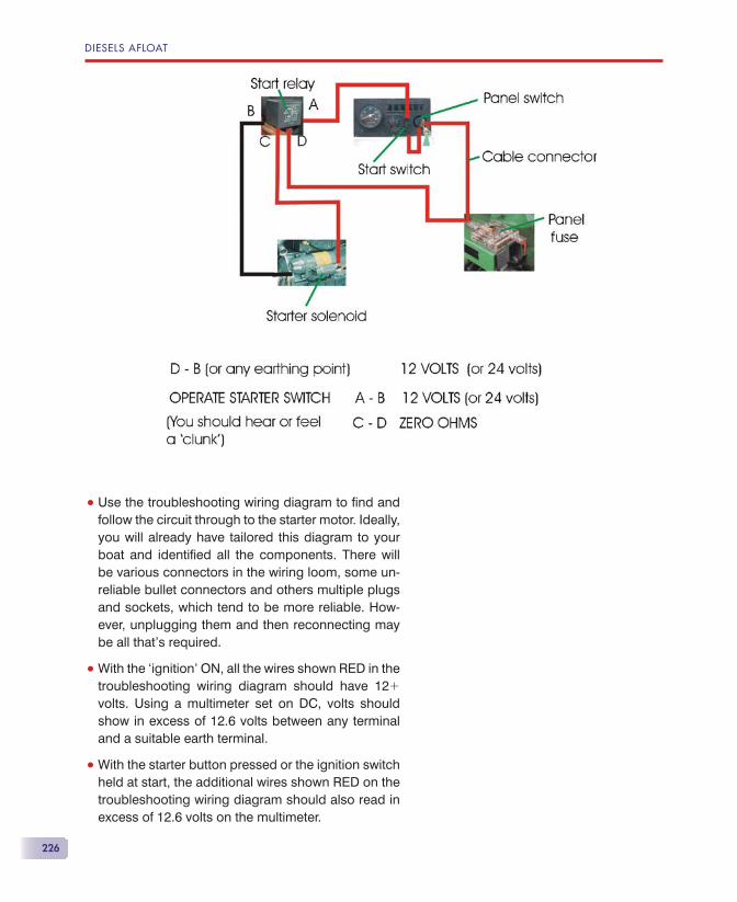
DIESELS AFLOAT
226
• Use the troubleshooting wiring diagram to fi nd and follow the circuit through to the starter motor. Ideally, you will already have tailored this diagram to your boat and identifi ed all the components. There will be various connectors in the wiring loom, some un-reliable bullet connectors and others multiple plugs and sockets, which tend to be more reliable. How-ever, unplugging them and then reconnecting may be all that’s required.
• With the ‘ignition’ ON, all the wires shown RED in the troubleshooting wiring diagram should have 12� volts. Using a multimeter set on DC, volts should show in excess of 12.6 volts between any terminal and a suitable earth terminal.
• With the starter button pressed or the ignition switch held at start, the additional wires shown RED on the troubleshooting wiring diagram should also read in excess of 12.6 volts on the multimeter.
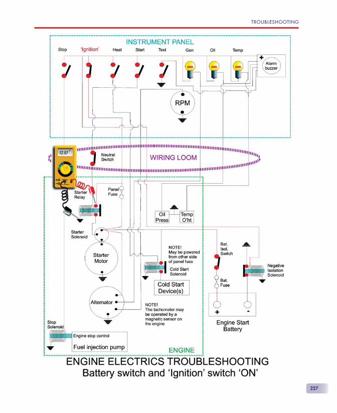
TROUBLESHOOTING
227
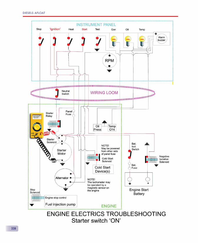
DIESELS AFLOAT
228
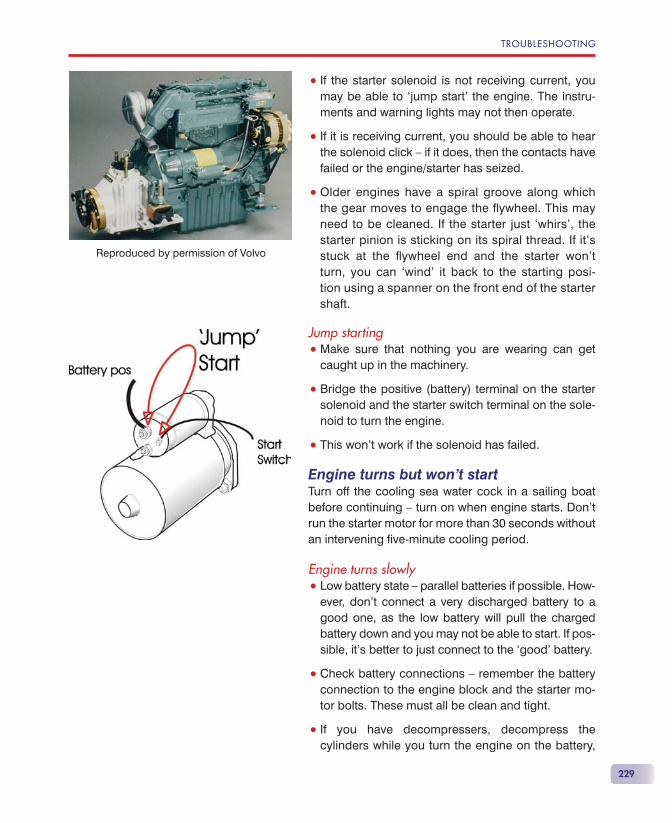
TROUBLESHOOTING
229
• If the starter solenoid is not receiving current, you may be able to ‘jump start’ the engine. The instru-ments and warning lights may not then operate.
• If it is receiving current, you should be able to hear the solenoid click — if it does, then the contacts have failed or the engine/starter has seized.
• Older engines have a spiral groove along which the gear moves to engage the fl ywheel. This may need to be cleaned. If the starter just ‘whirs’, the starter pinion is sticking on its spiral thread. If it’s stuck at the fl ywheel end and the starter won’t turn, you can ‘wind’ it back to the starting posi-tion using a spanner on the front end of the starter shaft.
Jump starting• Make sure that nothing you are wearing can get
caught up in the machinery.
• Bridge the positive (battery) terminal on the starter solenoid and the starter switch terminal on the sole-noid to turn the engine.
• This won’t work if the solenoid has failed.
Engine turns but won’t startTurn off the cooling sea water cock in a sailing boat before continuing — turn on when engine starts. Don’t run the starter motor for more than 30 seconds without an intervening fi ve-minute cooling period.
Engine turns slowly• Low battery state — parallel batteries if possible. How-
ever, don’t connect a very discharged battery to a good one, as the low battery will pull the charged battery down and you may not be able to start. If pos-sible, it’s better to just connect to the ‘good’ battery.
• Check battery connections — remember the battery connection to the engine block and the starter mo-tor bolts. These must all be clean and tight.
• If you have decompressers, decompress the cylinders while you turn the engine on the battery,
Reproduced by permission of Volvo
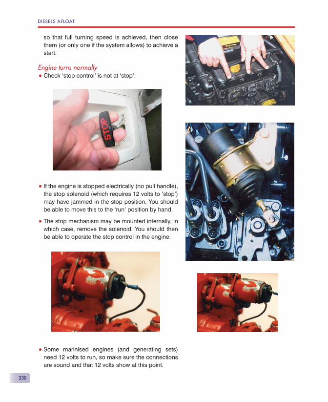
DIESELS AFLOAT
230
so that full turning speed is achieved, then close them (or only one if the system allows) to achieve a start.
Engine turns normally• Check ‘stop control’ is not at ‘stop’.
• If the engine is stopped electrically (no pull handle), the stop solenoid (which requires 12 volts to ‘stop’) may have jammed in the stop position. You should be able to move this to the ‘run’ position by hand.
• The stop mechanism may be mounted internally, in which case, remove the solenoid. You should then be able to operate the stop control in the engine.
• Some marinised engines (and generating sets) need 12 volts to run, so make sure the connections are sound and that 12 volts show at this point.
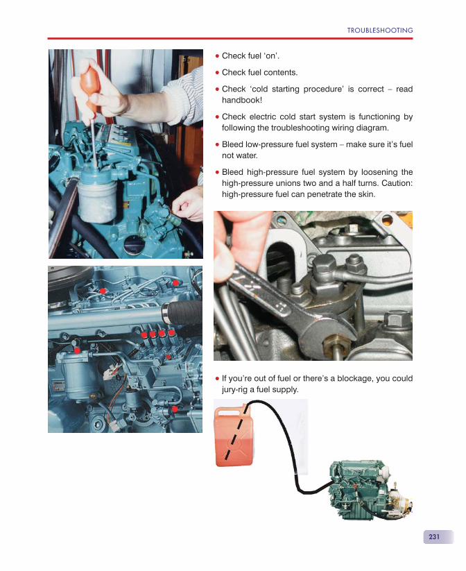
TROUBLESHOOTING
231
• Check fuel ‘on’.
• Check fuel contents.
• Check ‘cold starting procedure’ is correct — read handbook!
• Check electric cold start system is functioning by following the troubleshooting wiring diagram.
• Bleed low-pressure fuel system — make sure it’s fuel not water.
• Bleed high-pressure fuel system by loosening the high-pressure unions two and a half turns. Caution: high-pressure fuel can penetrate the skin.
• If you’re out of fuel or there’s a blockage, you could jury-rig a fuel supply.
DIESELS AFLOAT
232
DO NOT USE STARTING FLUID ON A DIESEL — ENGINE DAMAGE IS LIKELY. No current diesel engine manufacturer approves the use of starting fl uid. (If you must, spray some on a rag and hold the rag by the air intake as the engine is cranked. Get the engine over-hauled!)
A much safer way is to apply heat to the intake area and pre-heat the air as it’s sucked into the air intake. Remove the air cleaner and apply heat with a hair-dryer. Using exceptional care to prevent fi re and burn-ing electrical circuits, a gas blow-lamp can also be used in an emergency, but only if you’ll hit the rocks if you can’t start the engine!
Remember that diffi cult starting from cold indicates a faulty technique, poor battery or connections or an engine problem, which can include a bent connecting rod caused by water in the cylinder.
NO RESPONSE TO THROTTLEGenerally, this is just a matter of a cable becoming dis-connected.
• Stop the engine to ensure you don’t get caught up in moving machinery.
• Check if the speed lever on the engine moves when the throttle is opened.
• If it does, the problem is at the fuel injection pump and an engineer will be required.
• It will be obvious at this stage if the cable is con-nected to the engine speed lever.
• If it is, then you’ll need to look at the throttle control(s) and the dual-station box if fi tted.
NO RESPONSE TO GEARSELECTIONAll drive typesIt’s possible that weed, net or some other fouling is reducing thrust to zero, though it’s more likely that you would get at least some drive or visible disturbance of the water.
TROUBLESHOOTING
233
• Stop the engine to ensure you don’t get caught up in moving machinery.
• Check that the clutch lever on the gearbox responds to movement of the gear selector and that full move-ment is achieved, as specifi ed in the handbook/workshop manual.
• Check the oil level in the gearbox — if clutch opera-tion uses oil pressure, the clutch won’t engage if there’s no oil.
• If in doubt about the clutch lever operation over its full travel, disconnect the cable and operate the lever by hand and observe how far it moves to fully operate.
• Reconnect the cable and check that when the gear lever is moved, the clutch lever on the engine reach-es full travel.
Shaft drive systemsIf it does, start the engine.
• Ensure that there’s nothing that you are wearing, long hair, etc., that can get caught up in moving machinery.
• Select forward idle (or astern if that was the problem).
• Check that the gearbox/prop shaft coupling is rotating.
• If it isn’t, then the trouble is within the gearbox.— Volvo Penta 2000 series engines coupled to an MS2 gearbox have a known problem with the splined coupling on the gearbox input shaft. DB engineering have an excellent cure for this prob-lem.
• If the coupling rotates, observe the prop shaft to see if this is rotating as well.
• If no rotation, then the problem is the attachment of the coupling to the prop shaft.
• Some couplings have pinch bolts, so check their tightness.
DIESELS AFLOAT
234
• Some couplings have, in addition, a bolt or roll pin through both the coupling and shaft, and this may have sheared. If this has happened, you’ll need to replace the bolt or roll pin, but tightening the pinch bolts may get you home.
• If the prop shaft rotates, then the problem is at the propeller end.
Sail drive systemsAll the rest of the system is invisible.
• The problem could be within the gearbox/leg.
• The problem could be that the propeller is not rotat-ing or the propeller has fallen off.
• The boat will need to be lifted out of the water or someone will have to dive under the boat for further investigation.
Stern drive systemsBy tilting the leg up suffi ciently, you’ll be able to see if the prop is still there or if it’s rotating or not. However, some motor cruisers have such large bathing plat-forms that the props won’t be visible.
NO WATER FROM EXHAUSTOn many modern boats, the exhaust is not visible. If the exhaust is above the waterline, there will be a dis-tinct change in exhaust note when the exhaust is dry. If the exhaust is below the waterline, then your fi rst indication of a problem may be the engine overheat alarm sounding. In this case, the water pump impeller may already have been damaged. If you (or the en-gine or boat manufacturer) have fi tted a water intake or exhaust overheat warning system, this will operate to tell you that the cooling water fl ow has failed.
• Stop the engine if safe to do so.
• After a short while, restart the engine. This allows time for any plastic sheeting that may have blocked the intake temporarily to fl oat away.
• If the problem persists, check the weed strainer.
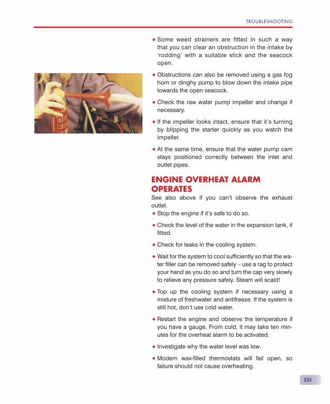
TROUBLESHOOTING
235
• Some weed strainers are fitted in such a way that you can clear an obstruction in the intake by ‘rodding’ with a suitable stick and the seacock open.
• Obstructions can also be removed using a gas fog horn or dinghy pump to blow down the intake pipe towards the open seacock.
• Check the raw water pump impeller and change if necessary.
• If the impeller looks intact, ensure that it’s turning by blipping the starter quickly as you watch the impeller.
• At the same time, ensure that the water pump cam stays positioned correctly between the inlet and outlet pipes.
ENGINE OVERHEAT ALARMOPERATESSee also above if you can’t observe the exhaust outlet.
• Stop the engine if it’s safe to do so.
• Check the level of the water in the expansion tank, if fi tted.
• Check for leaks in the cooling system.
• Wait for the system to cool suffi ciently so that the wa-ter fi ller can be removed safely — use a rag to protect your hand as you do so and turn the cap very slowly to relieve any pressure safely. Steam will scald!
• Top up the cooling system if necessary using a mixture of freshwater and antifreeze. If the system is still hot, don’t use cold water.
• Restart the engine and observe the temperature if you have a gauge. From cold, it may take ten min-utes for the overheat alarm to be activated.
• Investigate why the water level was low.
• Modern wax-fi lled thermostats will fail open, so failure should not cause overheating.
DIESELS AFLOAT
236
• Older, bellows-type thermostats will fail closed, so overheating is likely.
• Don’t run the engine with the thermostat removed, as engine damage due to undetected overheating is almost inevitable, despite what some books will tell you.
ENGINE LOW OIL PRESSURE ALARM OPERATES• Stop the engine if safe to do so.
• Check the oil level.
• Top up if necessary.
• If the engine is running very hot, the oil pressure may fall due to the oil becoming too ‘thin’.
• If the oil has been contaminated by diesel fuel — possibly a dribbling injector — the oil will be-come too ‘thin’.
• A worn engine may have too low an oil pressure at idle when the engine is hot.
• The oil pressure relief valve may have stuck open.
• The oil pressure pump may be worn.
• The oil fi lter may have become clogged and doesn’t have a bypass.
ALTERNATOR/GENERATORWARNING LIGHT ILLUMINATESIdeally, there will be a volt meter indicating system volt-age and, better still, an ammeter as well.
• Check the alternator output by means of the volt me-ter and the ammeter if fi tted.
• Advance the throttle from idle and check the light again.
• Note that some smart regulators have a ‘soft’ start, which allows the engine to warm up a little before the alternator starts to give any output.
TROUBLESHOOTING
237
• Stop the engine.
• Check the alternator (or dynamo/dynastart) drive belt.
• Check the connections on the alternator.
• If you have a smart regulator fi tted, check the diag-nostic lights if available.
• Call an engineer.

239
ENGINE SERVICINGThe best guide to servicing is the engine handbook. Although service intervals are normally governed by the number of engine hours since the last service, for the leisure boater, it’s more often dictated by the need to carry out a service at least annually.
Cooling system• Indirectly cooled (freshwater cooling like a car) en-
gines need to have the coolant replaced every sec-ond year. The coolant should be made up according to the engine handbook’s instructions, but is often 50% water and 50% antifreeze. Antifreeze contains corrosion inhibitors, which are consumed over a pe-riod of time and must be replaced. Checking with an antifreeze tester will not test the inhibitors. Cylinder- head gasket failure is common on engines which do not have this done.
• Raw water (‘direct’) cooled (sea, lake or river water cooling) engines often have sacrifi cial zinc anodes to prevent electrolytic corrosion of internal parts. These must be checked annually and replaced if more than half has been consumed.
• The heat exchangers of ‘direct’ cooling systems may have anodes, which need to be checked. These will be found in the raw water section of the heat
Maintenance
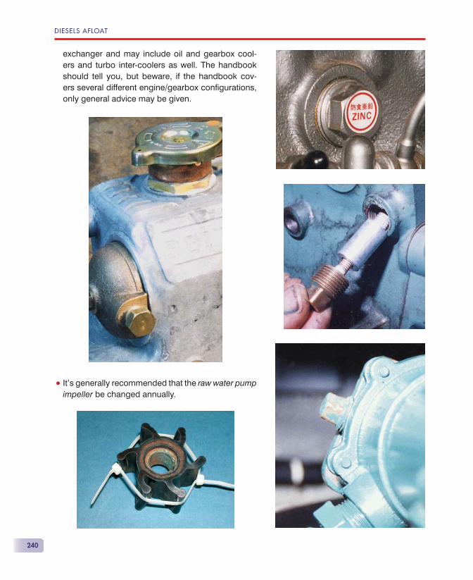
DIESELS AFLOAT
240
exchanger and may include oil and gearbox cool-ers and turbo inter-coolers as well. The handbook should tell you, but beware, if the handbook cov-ers several different engine/gearbox confi gurations, only general advice may be given.
• It’s generally recommended that the raw water pump impeller be changed annually.
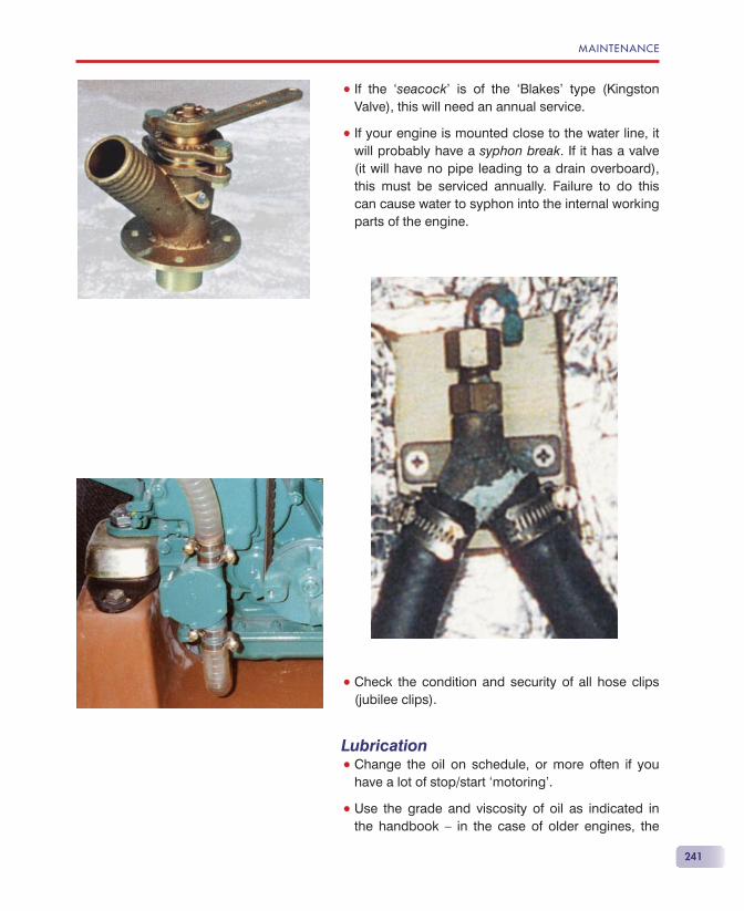
MAINTENANCE
241
• If the ‘seacock’ is of the ‘Blakes’ type (Kingston Valve), this will need an annual service.
• If your engine is mounted close to the water line, it will probably have a syphon break. If it has a valve (it will have no pipe leading to a drain overboard), this must be serviced annually. Failure to do this can cause water to syphon into the internal working parts of the engine.
• Check the condition and security of all hose clips (jubilee clips).
Lubrication• Change the oil on schedule, or more often if you
have a lot of stop/start ‘motoring’.
• Use the grade and viscosity of oil as indicated in the handbook — in the case of older engines, the
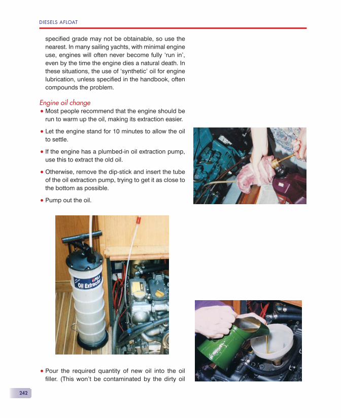
DIESELS AFLOAT
242
specifi ed grade may not be obtainable, so use the nearest. In many sailing yachts, with minimal engine use, engines will often never become fully ‘run in’, even by the time the engine dies a natural death. In these situations, the use of ‘synthetic’ oil for engine lubrication, unless specifi ed in the handbook, often compounds the problem.
Engine oil change• Most people recommend that the engine should be
run to warm up the oil, making its extraction easier.
• Let the engine stand for 10 minutes to allow the oil to settle.
• If the engine has a plumbed-in oil extraction pump, use this to extract the old oil.
• Otherwise, remove the dip-stick and insert the tube of the oil extraction pump, trying to get it as close to the bottom as possible.
• Pump out the oil.
• Pour the required quantity of new oil into the oil fi ller. (This won’t be contaminated by the dirty oil
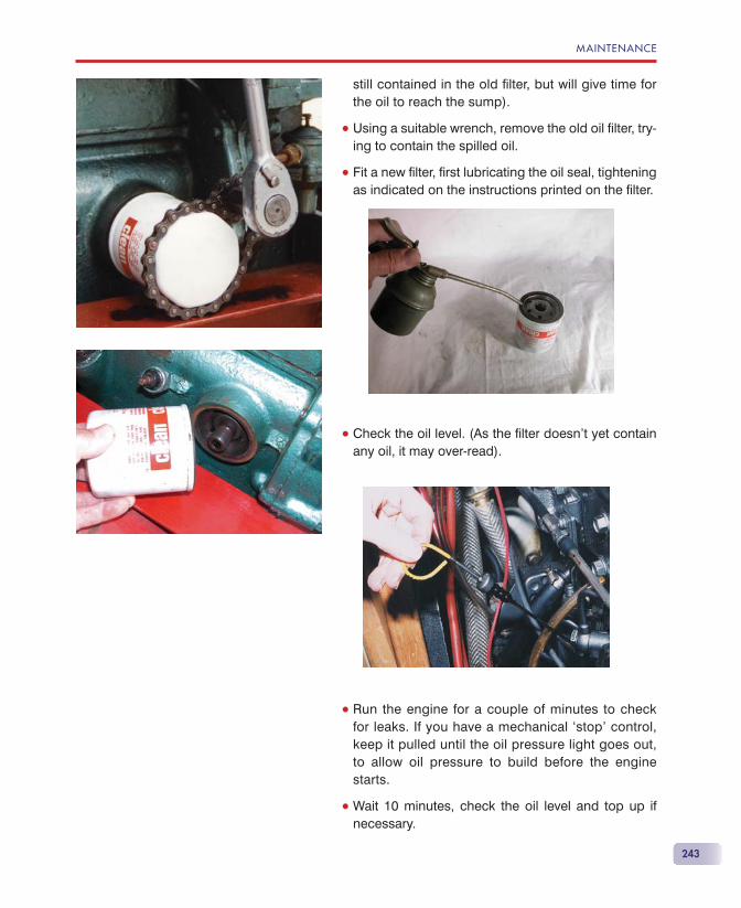
MAINTENANCE
243
still contained in the old fi lter, but will give time for the oil to reach the sump).
• Using a suitable wrench, remove the old oil fi lter, try-ing to contain the spilled oil.
• Fit a new fi lter, fi rst lubricating the oil seal, tightening as indicated on the instructions printed on the fi lter.
• Check the oil level. (As the fi lter doesn’t yet contain any oil, it may over-read).
• Run the engine for a couple of minutes to check for leaks. If you have a mechanical ‘stop’ control, keep it pulled until the oil pressure light goes out, to allow oil pressure to build before the engine starts.
• Wait 10 minutes, check the oil level and top up if necessary.
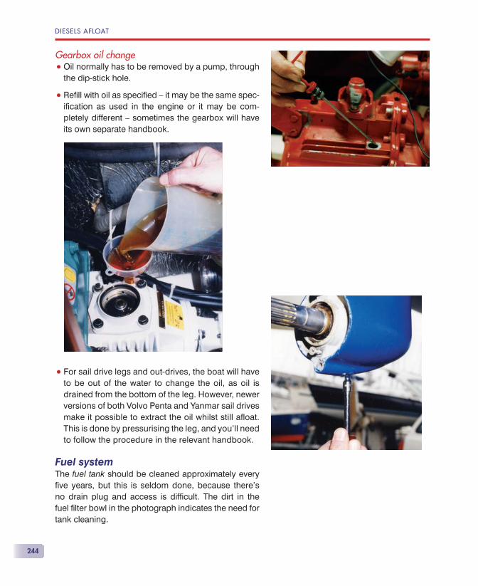
DIESELS AFLOAT
244
Gearbox oil change• Oil normally has to be removed by a pump, through
the dip-stick hole.
• Refi ll with oil as specifi ed — it may be the same spec-ifi cation as used in the engine or it may be com-pletely different — sometimes the gearbox will have its own separate handbook.
• For sail drive legs and out-drives, the boat will have to be out of the water to change the oil, as oil is drained from the bottom of the leg. However, newer versions of both Volvo Penta and Yanmar sail drives make it possible to extract the oil whilst still afl oat. This is done by pressurising the leg, and you’ll need to follow the procedure in the relevant handbook.
Fuel systemThe fuel tank should be cleaned approximately every fi ve years, but this is seldom done, because there’s no drain plug and access is diffi cult. The dirt in the fuel fi lter bowl in the photograph indicates the need for tank cleaning.
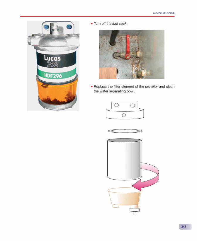
MAINTENANCE
245
• Turn off the fuel cock.
• Replace the fi lter element of the pre-fi lter and clean the water separating bowl.
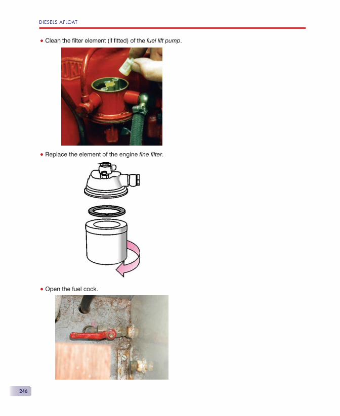
DIESELS AFLOAT
246
• Clean the fi lter element (if fi tted) of the fuel lift pump.
• Replace the element of the engine fi ne fi lter.
• Open the fuel cock.
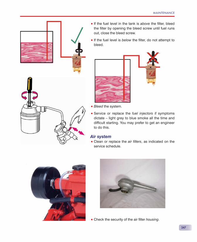
MAINTENANCE
247
• If the fuel level in the tank is above the fi lter, bleed the fi lter by opening the bleed screw until fuel runs out, close the bleed screw.
• If the fuel level is below the fi lter, do not attempt to bleed.
• Bleed the system.
• Service or replace the fuel injectors if symptoms dictate — light grey to blue smoke all the time and diffi cult starting. You may prefer to get an engineer to do this.
Air system• Clean or replace the air fi lters, as indicated on the
service schedule.
• Check the security of the air fi lter housing.
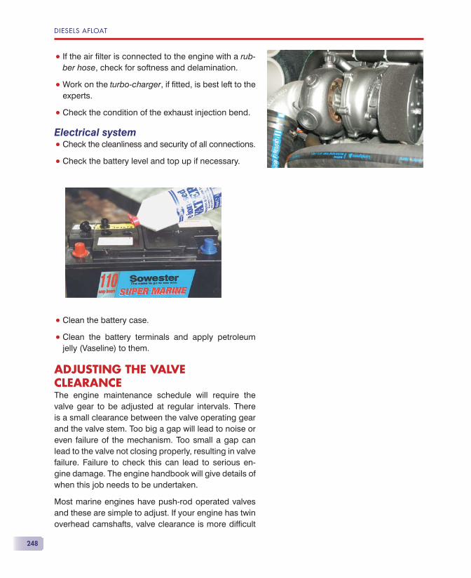
DIESELS AFLOAT
248
• If the air fi lter is connected to the engine with a rub-ber hose, check for softness and delamination.
• Work on the turbo-charger, if fi tted, is best left to the experts.
• Check the condition of the exhaust injection bend.
Electrical system• Check the cleanliness and security of all connections.
• Check the battery level and top up if necessary.
• Clean the battery case.
• Clean the battery terminals and apply petroleum jelly (Vaseline) to them.
ADJUSTING THE VALVE CLEARANCEThe engine maintenance schedule will require the valve gear to be adjusted at regular intervals. There is a small clearance between the valve operating gear and the valve stem. Too big a gap will lead to noise or even failure of the mechanism. Too small a gap can lead to the valve not closing properly, resulting in valve failure. Failure to check this can lead to serious en-gine damage. The engine handbook will give details of when this job needs to be undertaken.
Most marine engines have push-rod operated valves and these are simple to adjust. If your engine has twin overhead camshafts, valve clearance is more diffi cult
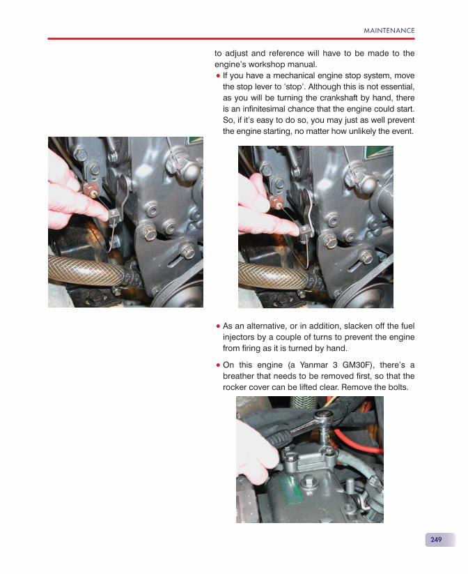
MAINTENANCE
249
to adjust and reference will have to be made to the engine’s workshop manual.
• If you have a mechanical engine stop system, move the stop lever to ‘stop’. Although this is not essential, as you will be turning the crankshaft by hand, there is an infi nitesimal chance that the engine could start. So, if it’s easy to do so, you may just as well prevent the engine starting, no matter how unlikely the event.
• As an alternative, or in addition, slacken off the fuel injectors by a couple of turns to prevent the engine from fi ring as it is turned by hand.
• On this engine (a Yanmar 3 GM30F), there’s a breather that needs to be removed fi rst, so that the rocker cover can be lifted clear. Remove the bolts.
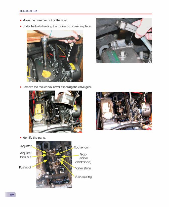
DIESELS AFLOAT
250
• Move the breather out of the way.
• Undo the bolts holding the rocker box cover in place.
• Remove the rocker box cover exposing the valve gear.
• Identify the parts.
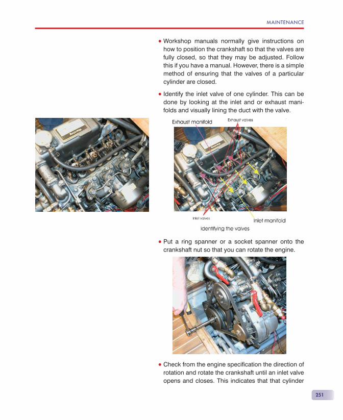
MAINTENANCE
251
• Workshop manuals normally give instructions on how to position the crankshaft so that the valves are fully closed, so that they may be adjusted. Follow this if you have a manual. However, there is a simple method of ensuring that the valves of a particular cylinder are closed.
• Identify the inlet valve of one cylinder. This can be done by looking at the inlet and or exhaust mani-folds and visually lining the duct with the valve.
• Put a ring spanner or a socket spanner onto the crankshaft nut so that you can rotate the engine.
• Check from the engine specifi cation the direction of rotation and rotate the crankshaft until an inlet valve opens and closes. This indicates that that cylinder
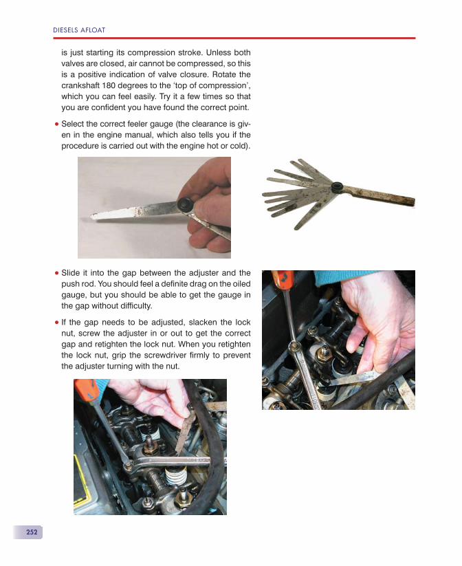
DIESELS AFLOAT
252
is just starting its compression stroke. Unless both valves are closed, air cannot be compressed, so this is a positive indication of valve closure. Rotate the crankshaft 180 degrees to the ‘top of compression’, which you can feel easily. Try it a few times so that you are confi dent you have found the correct point.
• Select the correct feeler gauge (the clearance is giv-en in the engine manual, which also tells you if the procedure is carried out with the engine hot or cold).
• Slide it into the gap between the adjuster and the push rod. You should feel a defi nite drag on the oiled gauge, but you should be able to get the gauge in the gap without diffi culty.
• If the gap needs to be adjusted, slacken the lock nut, screw the adjuster in or out to get the correct gap and retighten the lock nut. When you retighten the lock nut, grip the screwdriver fi rmly to prevent the adjuster turning with the nut.
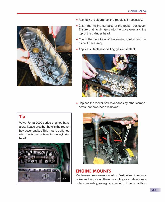
MAINTENANCE
253
• Recheck the clearance and readjust if necessary.
• Clean the mating surfaces of the rocker box cover. Ensure that no dirt gets into the valve gear and the top of the cylinder head.
• Check the condition of the sealing gasket and re-place if necessary.
• Apply a suitable non-setting gasket sealant.
• Replace the rocker box cover and any other compo-nents that have been removed.
ENGINE MOUNTSModern engines are mounted on fl exible feet to reduce noise and vibration. These mountings can deteriorate or fail completely, so regular checking of their condition
Tip
Volvo Penta 2000 series engines have a crankcase breather hole in the rocker box cover gasket. This must be aligned with the breather hole in the cylinder head.
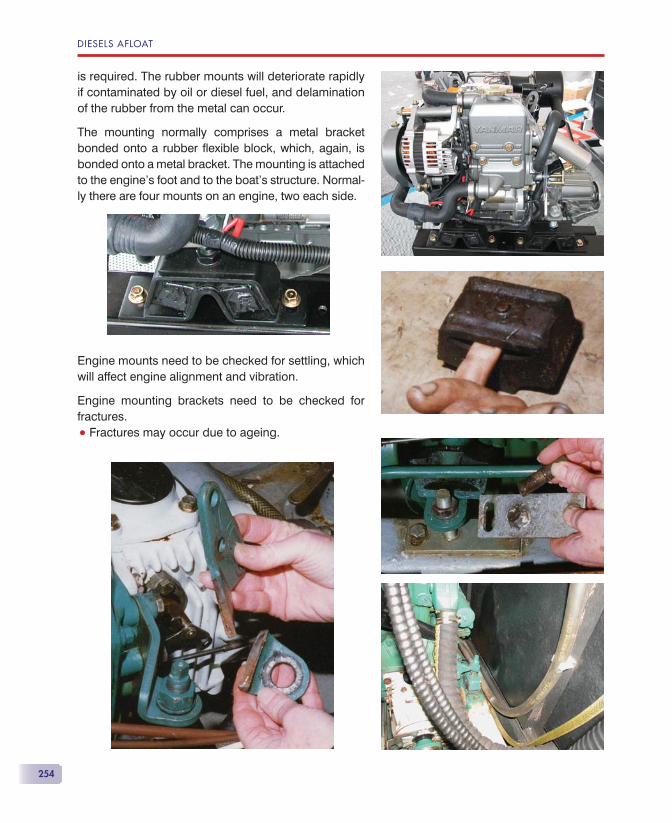
DIESELS AFLOAT
254
is required. The rubber mounts will deteriorate rapidly if contaminated by oil or diesel fuel, and delamination of the rubber from the metal can occur.
The mounting normally comprises a metal bracket bonded onto a rubber fl exible block, which, again, is bonded onto a metal bracket. The mounting is attached to the engine’s foot and to the boat’s structure. Normal-ly there are four mounts on an engine, two each side.
Engine mounts need to be checked for settling, which will affect engine alignment and vibration.
Engine mounting brackets need to be checked for fractures.
• Fractures may occur due to ageing.
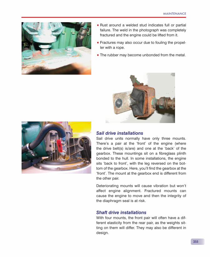
MAINTENANCE
255
• Rust around a welded stud indicates full or partial failure. The weld in the photograph was completely fractured and the engine could be lifted from it.
• Fractures may also occur due to fouling the propel-ler with a rope.
• The rubber may become unbonded from the metal.
Sail drive installationsSail drive units normally have only three mounts. There’s a pair at the ‘front’ of the engine (where the drive belt(s) is/are) and one at the ‘back’ of the gearbox. These mountings sit on a fi breglass plinth bonded to the hull. In some installations, the engine sits ‘back to front’, with the leg reversed on the bot-tom of the gearbox. Here, you’ll fi nd the gearbox at the ‘front’. The mount at the gearbox end is different from the other pair.
Deteriorating mounts will cause vibration but won’t affect engine alignment. Fractured mounts can cause the engine to move and then the integrity of the diaphragm seal is at risk.
Shaft drive installationsWith four mounts, the front pair will often have a dif-ferent elasticity from the rear pair, as the weights sit-ting on them will differ. They may also be different in design.
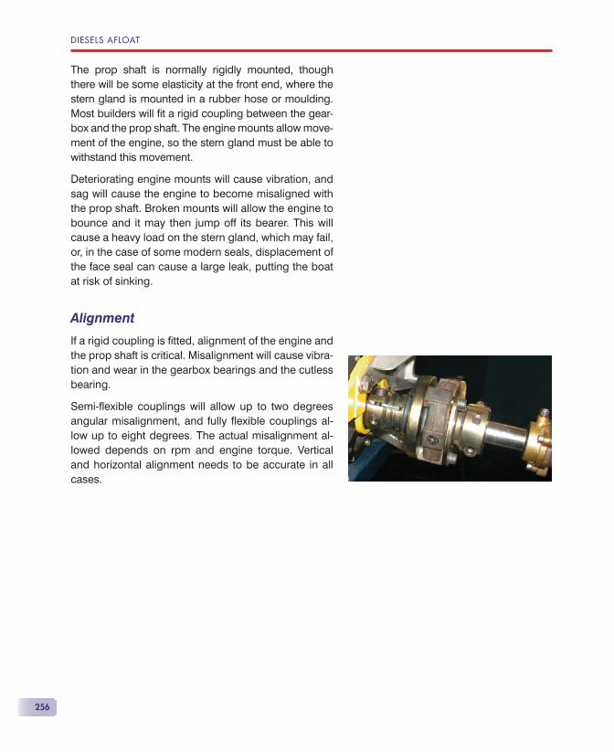
DIESELS AFLOAT
256
The prop shaft is normally rigidly mounted, though there will be some elasticity at the front end, where the stern gland is mounted in a rubber hose or moulding. Most builders will fi t a rigid coupling between the gear-box and the prop shaft. The engine mounts allow move-ment of the engine, so the stern gland must be able to withstand this movement.
Deteriorating engine mounts will cause vibration, and sag will cause the engine to become misaligned with the prop shaft. Broken mounts will allow the engine to bounce and it may then jump off its bearer. This will cause a heavy load on the stern gland, which may fail, or, in the case of some modern seals, displacement of the face seal can cause a large leak, putting the boat at risk of sinking.
Alignment
If a rigid coupling is fi tted, alignment of the engine and the prop shaft is critical. Misalignment will cause vibra-tion and wear in the gearbox bearings and the cutless bearing.
Semi-fl exible couplings will allow up to two degrees angular misalignment, and fully fl exible couplings al-low up to eight degrees. The actual misalignment al-lowed depends on rpm and engine torque. Vertical and horizontal alignment needs to be accurate in all cases.
257
If you are going to lay up your boat for the winter, the engine must be prepared so that it won’t suffer during the period that it’s not being used. Given the choice, I
would prefer to run the engine under load every couple of weeks, but do winterise the engine if you won’t be using it for more than six weeks. If you are going to lay up the engine for a lengthy period of time, consult your engine dealer for advice specifi c to your engine.
Make a list of everything done when you lay up the en-gine. Use this list when you recommission the engine to ensure everything is reinstated correctly.
FUEL TANKKeep the tank full, especially during the winter, to mini-mise condensation in the tank.
SERVICINGCarry out a full service of the engine and gearbox as required by their handbooks.
COOLING SYSTEMNote, you will be running the exposed engine. Ensure that neither you nor your clothes become entangled in rotating machinery.
• If you have direct cooling, run the engine until the thermostat is open. If you don’t have a temperature
Winterisation
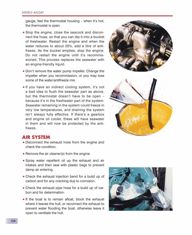
DIESELS AFLOAT
258
gauge, feel the thermostat housing — when it’s hot, the thermostat is open.
• Stop the engine, close the seacock and discon-nect the hose, so that you can dip it into a bucket of freshwater. Restart the engine and when the water reduces to about 25%, add a litre of anti-freeze. As the bucket empties, stop the engine. Do not restart the engine until it’s recommis-sioned. This process replaces the seawater with an engine-friendly liquid.
• Don’t remove the water pump impeller. Change the impeller when you recommission, or you may lose some of the water/antifreeze mix.
• If you have an indirect cooling system, it’s not a bad idea to flush the seawater part as above, but the thermostat doesn’t have to be open — because it’s in the freshwater part of the system. Seawater remaining in the system could freeze in very low temperatures, and draining the system isn’t always fully effective. If there’s a gearbox and engine oil cooler, these will have seawater in them and will now be protected by the anti-freeze.
AIR SYSTEM• Disconnect the exhaust hose from the engine and
check the condition.
• Remove the air cleaner(s) from the engine.
• Spray water repellent oil up the exhaust and air intakes and then seal with plastic bags to prevent damp air entering.
• Check the exhaust injection bend for a build up of carbon and for any cracking due to corrosion.
• Check the exhaust pipe hose for a build up of car-bon and for delamination.
• If the boat is to remain afl oat, block the exhaust where it leaves the hull, or reconnect the exhaust to prevent water fl ooding the boat, otherwise leave it open to ventilate the hull.
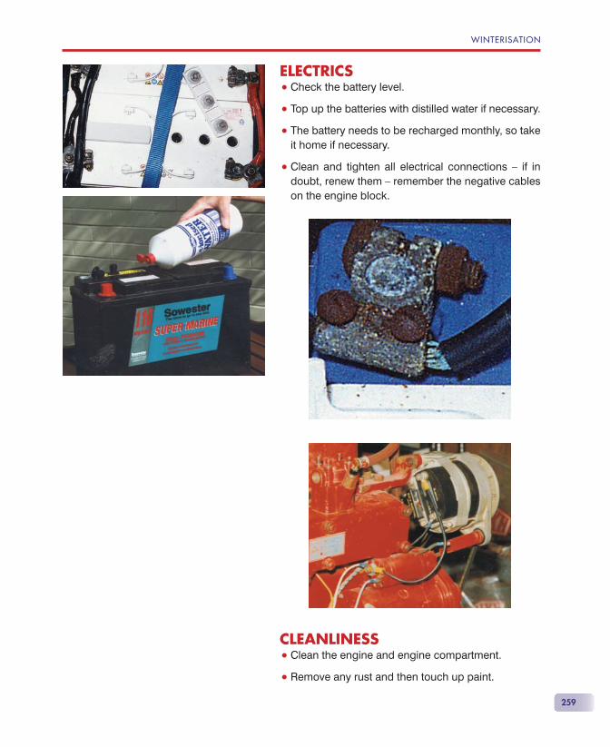
WINTERISATION
259
ELECTRICS• Check the battery level.
• Top up the batteries with distilled water if necessary.
• The battery needs to be recharged monthly, so take it home if necessary.
• Clean and tighten all electrical connections — if in doubt, renew them — remember the negative cables on the engine block.
CLEANLINESS• Clean the engine and engine compartment.
• Remove any rust and then touch up paint.
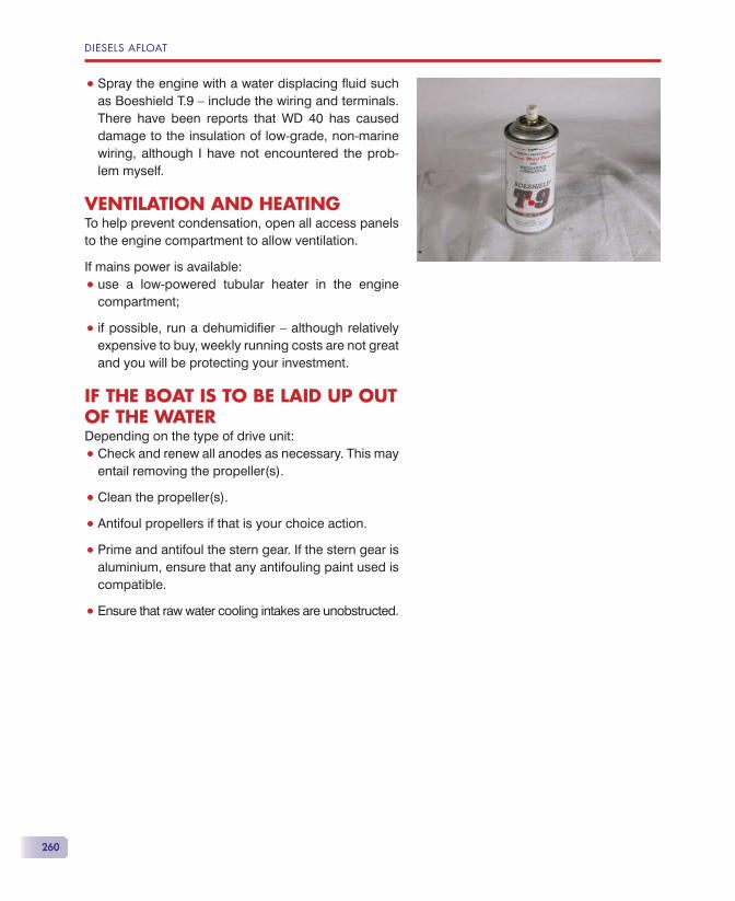
DIESELS AFLOAT
260
• Spray the engine with a water displacing fl uid such as Boeshield T.9 — include the wiring and terminals. There have been reports that WD 40 has caused damage to the insulation of low-grade, non-marine wiring, although I have not encountered the prob-lem myself.
VENTILATION AND HEATINGTo help prevent condensation, open all access panels to the engine compartment to allow ventilation.
If mains power is available:
• use a low-powered tubular heater in the engine compartment;
• if possible, run a dehumidifi er — although relatively expensive to buy, weekly running costs are not great and you will be protecting your investment.
IF THE BOAT IS TO BE LAID UP OUT OF THE WATERDepending on the type of drive unit:
• Check and renew all anodes as necessary. This may entail removing the propeller(s).
• Clean the propeller(s).
• Antifoul propellers if that is your choice action.
• Prime and antifoul the stern gear. If the stern gear is aluminium, ensure that any antifouling paint used is compatible.
• Ensure that raw water cooling intakes are unobstructed.

261
Ideally you would have made a list of everything that you did when you laid up the engine, noting those items that needed action when recommissioning.
Work methodically through your list, which will vary depending on the make of engine, gearbox and drive system.
• It’s essential to verify the watertight integrity of the vessel prior to relaunch.
• Some stern glands, such as the Volvo Penta, need to be squeezed to remove any trapped air immedi-ately after launching.
• Test run the engine and check all systems prior to proceeding ‘to sea’.
• Engine alignment should be checked about two weeks after launching to allow the hull to settle to its natural shape afl oat.
HORIZONTAL ALIGNMENTUnless the engine has been moved by disconnect-ing the mounting bases from the engine bearers, horizontal alignment (along the axis of the boat in plan view) will not change. Even then, if the same design of mounts and the same attachment holes are used, alignment will not be compromised seriously.
Recommissioning
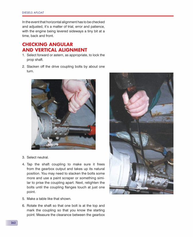
DIESELS AFLOAT
262
In the event that horizontal alignment has to be checked and adjusted, it’s a matter of trial, error and patience, with the engine being levered sideways a tiny bit at a time, back and front.
CHECKING ANGULAR AND VERTICAL ALIGNMENT
Select forward or astern, as appropriate, to lock the prop shaft.
Slacken off the drive coupling bolts by about one turn.
Select neutral.
Tap the shaft coupling to make sure it frees from the gearbox output and takes up its natural position. You may need to slacken the bolts some more and use a paint scraper or something simi-lar to prise the coupling apart. Next, retighten the bolts until the coupling fl anges touch at just one point.
Make a table like that shown.
6. Rotate the shaft so that one bolt is at the top and mark the coupling so that you know the starting point. Measure the clearance between the gearbox
1.
2.
3.
4.
5.
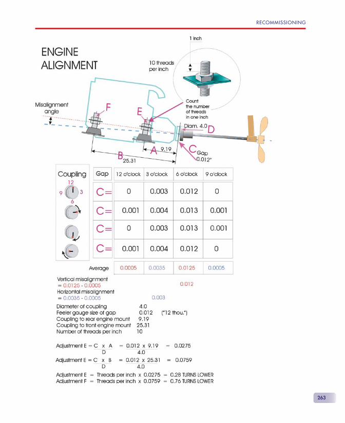
RECOMMISSIONING
263
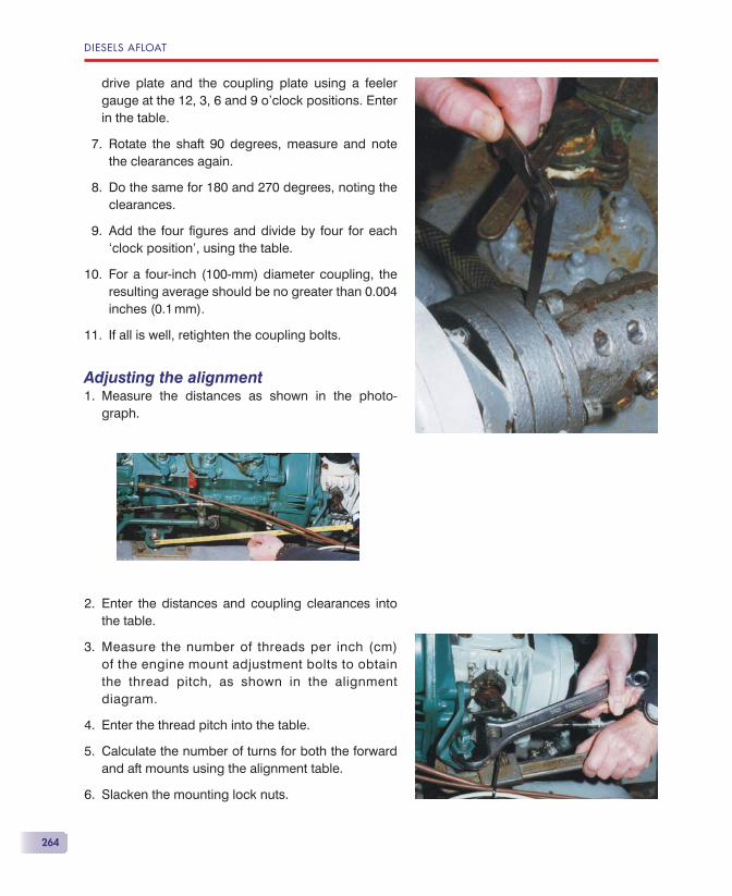
DIESELS AFLOAT
264
drive plate and the coupling plate using a feeler gauge at the 12, 3, 6 and 9 o’clock positions. Enter in the table.
7. Rotate the shaft 90 degrees, measure and note the clearances again.
8. Do the same for 180 and 270 degrees, noting the clearances.
9. Add the four fi gures and divide by four for each ‘clock position’, using the table.
10. For a four-inch (100-mm) diameter coupling, the resulting average should be no greater than 0.004 inches (0.1 mm).
11. If all is well, retighten the coupling bolts.
Adjusting the alignmentMeasure the distances as shown in the photo-graph.
Enter the distances and coupling clearances into the table.
Measure the number of threads per inch (cm) of the engine mount adjustment bolts to obtain the thread pitch, as shown in the alignment diagram.
Enter the thread pitch into the table.
Calculate the number of turns for both the forward and aft mounts using the alignment table.
Slacken the mounting lock nuts.
1.
2.
3.
4.
5.
6.
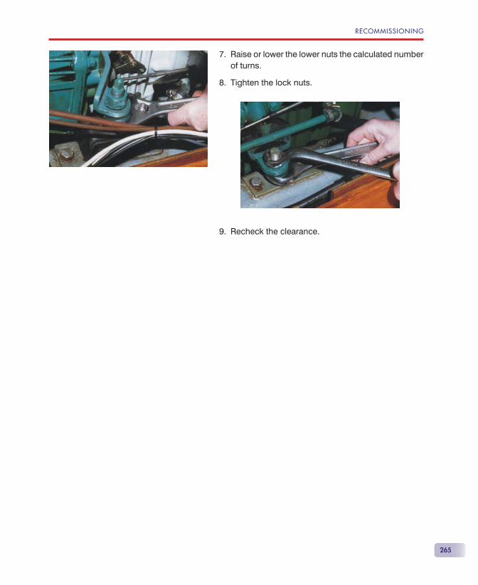
RECOMMISSIONING
265
Raise or lower the lower nuts the calculated number of turns.
Tighten the lock nuts.
Recheck the clearance.
7.
8.
9.


267
THE CAUSES OF FIRE IN ENGINE COMPARTMENTSOn diesel engine boats used for leisure purposes, the most likely cause of engine compartment fi res is an electrical short circuit or electrical component overheating. It is therefore essential that any electri-cal system running through the engine compartment can be isolated from outside. It is rare for the fuel system itself to cause the fi re, and normally the fuel system will become involved only if a fuel pipe burns through. However, if a fuel leak does occur, leaking fuel can come into contact with a hot component. A broken high-pressure fuel injection pipe allowing fuel to spray onto a hot turbo-charger casing or uncooled exhaust can cause a fi erce fi re in a very short space of time.
FIRE DETECTIONThe thing that worries me most about engine instal-lations in recreational sailing and motor yachts is the fact that there’s normally no fi re detection sys-tem. Ask yourself the question: ‘How would I know
EngineCompartmentFire Extinguishers
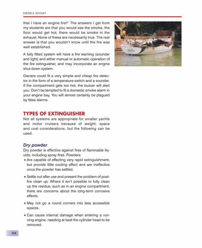
DIESELS AFLOAT
268
that I have an engine fi re?’ The answers I get from my students are that you would see the smoke, the fl oor would get hot, there would be smoke in the exhaust. None of these are necessarily true. The real answer is that you wouldn’t know until the fi re was well established.
A fully fi tted system will have a fi re warning (sounder and light) and either manual or automatic operation of the fi re extinguisher, and may incorporate an engine shut-down system.
Owners could fi t a very simple and cheap fi re detec-tor in the form of a temperature switch and a sounder. If the compartment gets too hot, the buzzer will alert you. Don’t be tempted to fi t a domestic smoke alarm in your engine bay. You will almost certainly be plagued by false alarms.
TYPES OF EXTINGUISHERNot all systems are appropriate for smaller yachts and motor cruisers because of weight, space and cost considerations, but the following can be used.
Dry powderDry powder is effective against fi res of fl ammable liq-uids, including spray fi res. Powders:
• Are capable of effecting very rapid extinguishment, but provide little cooling effect and are ineffective once the powder has settled.
• Settle out after use and present the problem of post-fi re clean up. Where it isn’t possible to fully clean up the residue, such as in an engine compartment, there are concerns about the long-term corrosive effects.
• May not go a round corners into less accessible spaces.
• Can cause internal damage when entering a run-ning engine, needing at best the cylinder head to be removed.

ENGINE COMPARTMENT FIRE EXTINGUISHERS
269
• Are not recommended for use in occupied spaces because they are unpleasant to breathe and ob-scure visibility.
Halocarbon gas systemsA number of fi re extinguishing halocarbon gases with zero ozone depletion potential (ODP) have been devel-oped. These include both HFCs (hydrofl uorocarbons) and PFCs (perfl uorocarbons). These new agents share many of the characteristics of the old Halons, but PFCs have been banned for marine applications by the IMO (International Maritime Organisation).
Although HFCs have zero ozone depletion potential, they have some global warming potential. They can be used in manned spaces, unlike Halon. They are full-fl ood systems that fi ll the whole protected space with the fi re suppression medium.
Fine solid particulate technologyAerosol and inert gases are formed pyrotechnically. The solid aerosol acts directly on the fl ame, cooling it; the gases deliver the aerosol to the fi re. Solid particulates have very high effectiveness to weight ratios. They are not suited for use in manned areas because the particulate material would be inhaled and the visibility severely reduced. Careful use and installation is required because of the extremely high burning temperature.
These may be automatic, electrically or manually operated.
DIFFERENT TYPES OF SYSTEMHand-held extinguisher discharged into the engine space from outsideIf you haven’t an automatic system, this is your only way of tackling an engine compartment fi re. Only an extinguisher suitable for use on electrical and liquid fuel should be used, and this will generally be of the dry powder type for recreational craft use. Access must be via a very small hole, so that extra oxygen is not admitted to the engine space, and many boats don’t have one. Opening the engine compartment
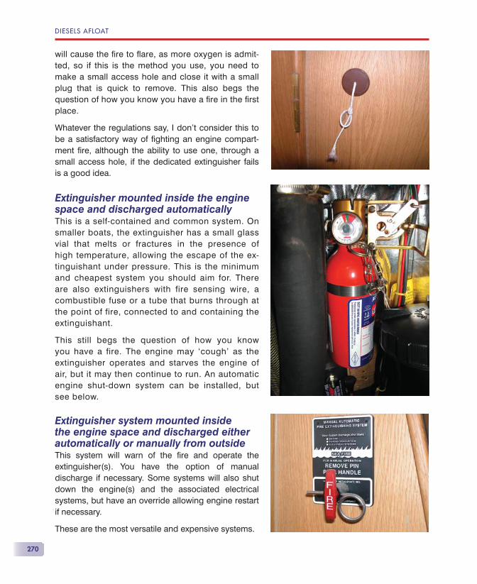
DIESELS AFLOAT
270
will cause the fi re to fl are, as more oxygen is admit-ted, so if this is the method you use, you need to make a small access hole and close it with a small plug that is quick to remove. This also begs the question of how you know you have a fi re in the fi rst place.
Whatever the regulations say, I don’t consider this to be a satisfactory way of fi ghting an engine compart-ment fi re, although the ability to use one, through a small access hole, if the dedicated extinguisher fails is a good idea.
Extinguisher mounted inside the engine space and discharged automaticallyThis is a self-contained and common system. On smaller boats, the extinguisher has a small glass vial that melts or fractures in the presence of high temperature, allowing the escape of the ex-tinguishant under pressure. This is the minimum and cheapest system you should aim for. There are also extinguishers with fire sensing wire, a combustible fuse or a tube that burns through at the point of fire, connected to and containing the extinguishant.
This still begs the question of how you know you have a fire. The engine may ‘cough’ as the extinguisher operates and starves the engine of air, but it may then continue to run. An automatic engine shut-down system can be installed, but see below.
Extinguisher system mounted inside the engine space and discharged either automatically or manually from outsideThis system will warn of the fi re and operate the extinguisher(s). You have the option of manual discharge if necessary. Some systems will also shut down the engine(s) and the associated electrical systems, but have an override allowing engine restart if necessary.
These are the most versatile and expensive systems.
ENGINE COMPARTMENT FIRE EXTINGUISHERS
271
AUTOMATIC OPERATIONHow automatic should the system be? There are two distinct schools of thought about this.
In big ships, a detection system alerts the crew, the crew decides what to do, the space is evacuated and the extinguishing system is operated. If the fi re is lo-calised, the fi re is attacked at that point manually by the crew.
In aircraft, the system is never automatic, the crew is alerted and then takes the appropriate action accord-ing to the circumstances.
In small boats, there is sometimes an automatic fi re extinguisher in the engine compartment. Some of the newly introduced systems follow this automatic opera-tion with automatic disconnection of the engine elec-trical system, but others give a fi re warning but with electrical activation by the crew and no automatic shut down.
In my opinion, the fi rst requirement of the system is to alert the crew. This should be standard on all boats. This warning device could operate the extinguisher automatically (or automatic extinguisher operation could alert the crew), or allow the crew to operate the system manually. Whether the electrical system should also be shut off is open to debate. On most marine diesels with electric stop solenoids, you need electrical power to stop the engine. If the power is removed, you may not be able to stop the engine if you wish. The corollary to this is that most diesel engine room fi res are of electrical origin, so one of the fi rst actions should be to switch off the power. A recent fi re on board a new motor cruiser was tackled by the automatic fi re extinguisher. The powerful twin engines continued to run and the extinguishant was sucked straight through the engines and the fi re was not put out. Automatic engine shut down would have ensured that the fi re was extinguished.
You should also turn off the fuel supply from the tank, so this must be accessible from outside the engine compartment.
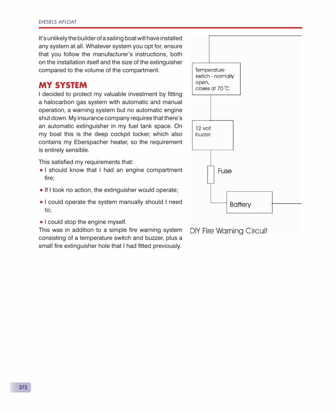
DIESELS AFLOAT
272
It’s unlikely the builder of a sailing boat will have installed any system at all. Whatever system you opt for, ensure that you follow the manufacturer’s instructions, both on the installation itself and the size of the extinguisher compared to the volume of the compartment.
MY SYSTEMI decided to protect my valuable investment by fi tting a halocarbon gas system with automatic and manual operation, a warning system but no automatic engine shut down. My insurance company requires that there’s an automatic extinguisher in my fuel tank space. On my boat this is the deep cockpit locker, which also contains my Eberspacher heater, so the requirement is entirely sensible.
This satisfi ed my requirements that:
• I should know that I had an engine compartment fi re;
• If I took no action, the extinguisher would operate;
• I could operate the system manually should I need to;
• I could stop the engine myself.This was in addition to a simple fi re warning system consisting of a temperature switch and buzzer, plus a small fi re extinguisher hole that I had fi tted previously.
273
here should always be a basic toolkit on the boat. This should include:
• tools for routine engine servicing;
• tools for routine boat work.
Some of these tools will be common to both catego-ries. Additionally, a more extensive kit will be needed according to the amount of work you intend doing yourself.
ENGINE TOOLS• Set of open-ended spanners (6 mm—17 mm).
• Set of ring spanners (10 mm—17 mm).
• Set of socket spanners (6 mm—17 mm).
• Adjustable spanners.
• Self-gripping wrench.
• Set of fl at-blade screwdrivers.
• Set of cross-head screwdrivers.
• Pliers.
• Long-nose pliers.
Note!
If your engine is older, you will need a set of A/F or even Whitworth and BSF spanners.
T
Tools
DIESELS AFLOAT
274
• Side-cutting pliers.
• Set of Allen keys (hexagonal wrenches).
• Set of feeler gauges.
• Ball pein hammer.
• Hide or rubber hammer.
• Hobby knife.
• Oil fi lter wrench.
• Sump pump.
• Magnet on a stick.
• Mirror on a stick.
• Torch (preferably a head torch).
ENGINE SPARES AND CONSUMABLES• Self-amalgamating tape.
• Insulating tape.
• Cable ties.
• Liquid gasket.
• Thread-locking compound.
• PTFE thread-sealing tape.
• Water-displacing fl uid.
• A range of jubilee clips (hose clamps).
• Spare coolant hose.
• Spare fuel hose.
• Spare fuses.
• Grease.
• Vaseline (petroleum jelly).
• Engine service spares.
• Primary fuel fi lter.

TOOLS
275
• Engine fuel fi lter.
• Oil fi lter.
• Drive belts.
• Engine oil.
• Gearbox oil.
• Raw water pump impeller and gasket.


277
Air fi lter/silencer, 130maintenance, 130pre-heating air, 28
Air supply, restrictions, 37Air system, 127
engine cooling, 77, 84, 94, 108, 112, 257, 239air cooling, 77
maintenance, 239normally aspirated, 14, 122turbo-charged, see Turbo-charging, 13, 37winterization, 257
Alternator, 143, 144, 146, 147, 150, 156, 157, 164, 165, 166, 179, 180, 181, 236, 237
belt drive, 142short life, 181tension adjustment, 179tension measurement, 180
engine-driven 12-volt DC, 139brushes, 143brushes, replacing, 144output, 165output, higher, 139, 142second unit, 138size required, 141starting load, 142voltage regulation, 143
warning light, 138, 143Anodes, 102—104, 105, 218
cooling system, 80, 104
changing, 105checking, 105electrical contact with carrier, 105freshwater-cooled engines, 104heat exchanger, 95, 105location, 104raw-water-cooled engines, 103
engine, 104, 105when laying up out of the water, 260propeller, 260, 7
Antifouling, 260Antifreeze, 109, 110, 112, 113, 235, 239, 258
changing, 112protection, 109, 110types, 109
Archimedes, 204
Batteries, 141—144, 146, 150, 157, 159, 160—162,absorbed glass mat (AGM), 160ageing, 162
Checking, 163charge, measuring state of, 161
ammeter and voltmeter, 161amp hour meter, 162hydrometer, 161
charging, 8, 42, 140—143, 159, 164, 167, 179from mains charger, 159, 167
deep cycle, 159, 160, 162gel, 160, 162
Index

INDEX
278
Batteries (continued)general purpose, 157lead acid, 157, 158, 162, 164
engine start, 157—159service, 158, 163topping up, 164
maintenance-free, 153nickel-cadmium (Ni-Cd), 160self-discharge, 160, 162, 167sulphation, 162, 163, 166
Battery, 134, 139, 137, 167chargers, 167fuse, 137switch, 134, 139
Boeshield T.9, 260Brunel, Isambard Kingdom, 204Brunton Propellers Autoprop, 216, 221
Calorifi ers, 113Cam-belts, rubber, 31Camshaft, 30, 31, 248
overhead, valves operated by, 30CAV, 57Charge regulators, 162, 166
‘smart’, 143, 166, 167fi tting, 146
Cold start relay, 136Combustion (‘swirl’) chamber, 25Compression ignition, 9Consumables, 274Cooling system, 77—80, 82, 86, 92, 94, 95, 97, 99,
102, 104, 105, 109—112air cooling, 77
cooling, 77, 78, 80, 82, 86, 92, 94, 95, 97, 99, 102, 104, 105, 109—112
anodes, see anodes: cooling system, 104antifreeze, see antifreeze, 109, 110, 112, 113,
235, 239anti-syphon valve, see syphon break, 97coolant, 110, 239draining, 112
freshwater systems, 114raw water systems, 113
dry riser, 109, 110freshwater circulating pump, 91heat exchangers, see heat exchangers, 92
maintenance, 239refi lling, 112
bleed points, 113freshwater systems, 114raw water systems, 113
seacock, ‘Blake’ type (Kingston Valve), 241seawater pump, see seawater (raw water) pump, 82syphon break, see syphon break, 96thermostat, see thermostst, 99water cooling, 77, 79
direct (raw water), 77exhaust, 78indirect (fresh water), 78keel, 78, 82troubleshooting, 235
water fl ow failure, 82water injection bend, 79, 108water-logged engine, 110
starting, 111water strainers, see water strainers, 105winterization, 115, 257
Corrosion, electrolytic, 6, 7, 137, 239Cylinder bore glazing, 39, 40
bore polishing, 41prevention, 42
compression, 40grooves (honing), 40oil, 40pressure, insuffi cient, 41prevention, 42re-honing, 43
DB Marine, 177Decompressors, 31, 32Dehumidifi er for winterization, 260Detroit Diesels, 19, 21Diesel, Rudolf, 1Diesel engine, 1, 2, 9, 10, 13, 19, 25, 30, 32, 36, 40,
42, 49, 50, 70, 122, 123, 127, 133, 150modern, 2
type required, 10two-stroke diesel engine, 19
small marine, development of, 2, 26Drive, 4—8, 105
sail, see sail drive, 6shaft, see shaft drive, 4

INDEX
279
stern, see stern drive, 5‘V’, 5‘Z’, 5, 174—176
Drive belts, 179, 275short life, 181tension adjustment, 179tension measurement, 180
Dynamo, 134, 138, 156, 179, 237Dynastart, 156, 157, 237
Electrics, engine, 137batteries; starter motor, 136, 151, 229battery, 137, 139, 159
chargers, 159fuse, 137switch, 139
block diagrams, 133start circuit, 133
cold start, 136, 231relay, 136system, 231
dynamo, 139dynastart, 157engine ‘fuse’, 141, 231‘ignition’ key, 139‘ignition’ switch, 137isolation solenoid, ‘negative’, 137maintenance, 248starter relay, 136starter solenoid, 136stop control, 163, 230stop solenoid, 136tachometer, 138troubleshooting, see troubleshooting: engine
won’t start — electrics, 134, 137warning ‘buzzer’, 139warning lights, 138, 225, 229winterization, 257
Electronic engine management, 197, 200control system, 187function, 198instruments, digital, 199troubleshooting, 200Volvo Penta IPS engines, 199
Engine and prop shaft alignment, 261—263recommissioning: engine alignment, 261
Engine fi ne fi lter, 63bowl type, 64‘spin off’ type, 63, 65
Engine ‘fuse’, 225Engine management, electronic, see Electronic
engine management, 4, 136, 197, 198, 200
Engine mounts, maintenance, 254, 255sail drives, 255shaft drive, 255
Engine mounts, recommissioning, 264Engine operation, correct, 49Engine power, 43
fuel consumption, curves, specifi c, 44manufacturer’s fi gures, meaning, 45motor cruisers, 46performance curves, 48propeller law power curves, 44sailing yachts, 47torque curves, 44
Engine servicing, see Maintenance: engine servicing, 239
Engine won’t start, see Troubleshooting: engine fails to start, 137
Exhaust, 96, 197, 248, 258emissions, control of, 197injection bend, 96, 248, 258pipe hose, 258
Exhaust smoke, see Smoke in the exhaust, 35Exhaust system, 39, 82, 96, 108, 110, 127
blockages, 110dry riser, 109, 110no water from, 82sailing yachts, 110water injection bend, 108
Exhaust valves, 10, 20, 29adjusting clearance, 30
Fault prevention, 223Feeler gauge, 252, 264, 274Fire detection, 267
warning device, 271Fire extinguishers, engine compartment, 267
automatic operation, 276electrical system, shutting off, 270systems, 261, 268—271

INDEX
280
Fire extinguishers (continued)types, 268
dry powder, 268fi ne solid particulate, 269halocarbon gas systems, 269
Fire in engine compartments, causes, 267Ford 1.5/1.8-derived engines, 31Ford Escort engine, 31Four stroke cycle, 10
compression stroke, 10exhaust stroke, 11ignition, 10, 13induction stroke, 10multi-cylinder engines, 13power stroke, 11, 13
Freshwater circulating pump, 91, 92Fuel, biological contamination, 72—74
fi lter, primary: draining water, 55—56biocides, 73enzyme fuel additives, 73—74magnetic fuel conditioners, 73water removers, 73
Fuel consumption, specifi c (SFC), 48, 49Fuel cut-off, 70—72Fuel fi lter, primary, 68—70
CAV, 57draining water, 55—57
contamination, 72—74Lucas, 144—146position and purpose, 159servicing, 158transparent bowl, 55—56, 73
Fuel gauges, 55Fuel injectors, 57, 62, 65—68
common rail injection, 25, 26direct injection, 24, 25indirect injection, 25
pre-heating engine, 29Fuel injection pump, 33—35, 38, 65, 66
bleed point, 68—70combined with fuel injector, 25, 26fuel rack, 22
stopping the engine, 70—72governor, 21, 33—35location, 35plunger (piston), 22, 69
servicing, 56, 57timing, incorrect, 38, 65
Fuel injectors, 66combined with fuel injection pump, 26servicing, 56, 65worn, 38
Fuel lift pump, 57—62attached to injection pump, 57diaphragm, changing, 57fi lter, cleaning, 57—58later types, 58location, 58priming lever, 62removing, 65, 66separate pumps, 66valves, 61
Fuel system, 66—68air removal (bleeding, priming, venting), 68—70troubleshooting, 225winterization, 74—75
Fuel tank, 51—54baffl es, 53cleaning, 54construction, 52drain cock, 52draining, 54fi lter/strainer, 54isolation valve (fuel cock), 54—55sight gauge, 55sludge/dirt trap, 51winterization, 257—260
Gear selection, see Throttle and gear selection, 183
gearbox, 169astern drive, 170clutches, 170drive, loss of, 176—177forward drive, 170gearwheels, 170maintenance, 175—176neutral, 174, 184, 186oil, 175oil change, 126, 175speed reduction, 169troubleshooting, 176

INDEX
281
types, 170bevel gears, 174
epicyclic, 173—174layshaft, 172two-shaft, 170—171Volvo Penta MS2, 177
Glow (pre-heater) plugs, 27Great Britain, SS, 204
Heat exchangers, 78anodes, 96, 103blockage, 107multiple seawater-cooled, 86problems, 86—89tube stack, 92—94
Heating for winterization, 260Hitachi, 146Hull types, engines for, 3—4Hydrometer, 160—163
Ignition, compression, 9—10‘Ignition’ key, 71, 139, 197‘Ignition’ switch, 54, 137Inlet valves, 10, 29, 61, 251
adjusting clearance, 248—253Instruction books, 49—50Isolation solenoid, ‘negative’, 137
Lombardini, 26Lubrication system, 117—126
lubricating, 117crankcase breather, 120gearbox, see oil, gearbox, 126low oil pressure alarm, 236—242maintenance, 239oil fi lter, 119oil pump, 117—119pressure relief valve, 119, 236sump (oil pan), 117—118
strainer, 118system, 118
Lucas, 57, 144
Maintenance, 239—256anodes, 239antifreeze, 239
engine and prop shaft alignment, 256recommissioning: engine alignment,
261engine mounts, 261—264
air system, 247—248cooling system, 257—258electrical system, 248engine servicing, 239—256fuel system, 244—247lubrication/oil changing, 242—244sail drive, 234shaft drive, 233
valve clearance, adjusting, 248—252Moody boats, 54
Newton’s laws of motion, 204
Oil, engine lubricating, 121—126lubrication system, 117changing, 123—126
frequency, 121cooling, 122corrosion, inhibiting, 122cylinder bore glazing, 39functions, 121—122lubrication requirements, 121specifi cation, 122—123type required, 123
Oil, 118—120, 126, 244,fi lter, 119—120gearbox, 169
changing, 126, 244pressure pump, 118, 119pressure relief valve, 119
Optima batteries, 159Outdrive, see Stern drive, 5—6
Perkins engines, 28bleed points, 70—71
Petter engines, 1, 27Anodes, 103mini 6 and mini twin, 27, 103
Piston rings, 10, 40, 42Plugs, pre-heater (glow), 27Propeller Handbook, 221Propeller shaft, see Shaft drive, 4

INDEX
282
Propeller(s), 4, 209—227anodes, 218blade lift and drag, 204calculations, 211—212choice of, 212, 218—220
for displacement motor boats, 212for planing motor boats, 214for sailing yachts, 218, 220, 225—226, 227
clearance, 213diameter, 209, 213effi ciency, 205, 211—212fi xed pitch, 210function, 210gear ratio, 218how they work, 204mounting, 4pitch, 207—221power curve, 212rotation, direction of, 214sailing drag, 214—216, 219sized for max speed, power & rpm, 212slip, 204, 207, 211when laying up out of the water, 266thrust, 204—210, 213—221
aeration, 208blade area, 206, 208—209blade area ratio, 209, 214blade twist, 209, 211, 217cavitation, 207—210, 214—216diameter, 203, 206, 207, 209, 213—214pitch, 203, 205, 210, 212, 215, 216, 218reverse, 214, 216, 220
types, 209, 217—219autoprop, 216, 217, 219, 221feathering, 213—216, 218—220fi xed blade, 209, 214, 217, 221, 223, 225—227folding, 209—210, 213—214, 218—220for planing motor boats, 214self-pitching, 216, 217, 219variable pitch, 216, 217
water fl ow past, 215, 219—220Push-rod-operated valves, 30
Recommissioning, 261—265engine alignment, see also engine and prop shaft
alignment, 261—265
adjusting, 264—265checking, 262—265horizontal, 261—262
Rocker box cover, 250—253
Sabb engines, 27, 28, 91Sail drive, 6—8, 105, 126, 138, 143, 174—176,
218engine mount maintenance, 253—264external water temperature, 8oil change, 7, 126, 244rubber diaphragm, 7troubleshooting, 234Volvo Penta, 7, 105, 109—110, 175, 218, 224, 230,
244, 250Yanmar, 7, 138, 143, 244
Screw, see Propellers, 203—205Seacock, ‘Blake’ type (Kingston Valve), 241Seawater (raw water) pump, 82—91
belt-driven, 91failure causes, 86—89impeller, 85—90
changing, 84location, 85—86principle, 83Sabb engines, 91servicing, 89—91Volvo Penta MD2000 series engines, 90
Shaft drive 4—5, see also Engine and prop shaftalignment, 256
couplings, 233—234, 256, 262—265engine mount maintenance, 253—255thrust angle/line, 5, 6thrust bearings, 5troubleshooting, 233—234
Smoke in the exhaust, 35—39black, 35—37
acceleration, 36other, 37overload, 37
blue, 37—39white, 39
Soltron, 73—74Spares, 274—275Speed control, 32—35
accelerating the engine, 34

INDEX
283
governor, 33—35, 40—41electronic, 35hydraulic, 35location, 35weights, 33—34
slowing the engine, 34—35speed control lever, see ‘throttle’, 33too much load, 35
Starter motor, 136, 150—156Bendix drive, 150—151brushes, replacing, 154—156checking engagement mechanism, 153—154checking operation, 154maintenance, 152—153pre-engaged, 150, 151—152
Starter relay, 136Starter solenoid, 136Starting, cold, 26
compression ratio, raising, 27fuel, extra, 26pre-heating, 27
chemical igniters, 28electric heater in air intake, 29Thermostart, 28
Starting, requirements for, 13, 15Starting fl uid, 232Starting water-logged engine, 111Stern drive (outdrive), 5, 6, 8, 234
changing gearbox oil, 244troubleshooting, 234
Stern gear, when laying up out of the water, 260Stern glands, recommissioning, 261Stop control, 72, 120, 125, 163, 201, 230, 243Stop solenoid, 136, 137, 230Stopping the engine, 70, 120
electrically, 71mechanically, 71
Sump (oil pan), 117strainer, 117, 118
Super-charging, 18Syphon break, 96, 97, 241
anti-syphon valve, 97, 98cleaning, 98Volvo Penta, 98
maintenance, 241seawater in working parts of engine, 96
system, 96—98
Tachometer, 138Thermostat, 99—101
changing, 101failure, 101location, 101operation, 99running while removed, 102testing, 102
‘Throttle’ (speed control lever), 33accelerating and slowing the engine, 34smoke in the exhaust, 35
Throttle and gear selection, 183dual-station systems, 186
gear, 186throttle, 186
electronic systems, 187maintenance of selectors, 190
cables, replacing, 196friction adjustment, 190Whitlock unit, changing, 190
operating cables, 188single-lever controls, 184
disengaging gear linkage, 185forward, 184reverse, 185starting in gear, ‘micro-switch’ preventing, 186
troubleshooting, 225, 226, 231shaft drive systems, 233
twin-lever systems, 183Tools, 273Troubleshooting, 225
alternator/generator warning light illuminates, 236engine low oil pressure alarm operates, 236engine overheat alarm sounds, 231engine turns but won’t start, 229
air, pre-heating, 232engine turns normally, 230engine turns slowly, 229fuel system, 231
engine won’t start, 225electrics, 227fails to turn, 225‘jump’ starting, 229wiring diagrams, 227

INDEX
284
Troubleshooting, (continued)exhaust, no water from, 234gear selection, no response to, 232throttle, no response to, 232
True Marine ‘Speed Seal’, 85Turbo-charging, 13
inter-cooler (heat exchanger), 17life of, extending, 18limitations in boat types, 17operation, 14power output, 14, 19principle of, 14smoke, black, 35temperatures, 14waste gate, 17
Two-stroke diesel engine, 19compression phase, 19exhaust phase, 20ignition phase, 20inlet phase/ports, 19power phase, 20
‘V’ drive, 5Valve gear, 29
adjusting clearance, 30camshaft, 29, 30exhaust valves, 29inlet valves, 29overhead camshaft-operated valves, 30push-rod-operated valves, 30
Ventilation for winterization, 258, 260Vetus engines, 31Volkswagen Golf-derived engine, 31Volvo Penta engines, 9, 19
Anodes, 103anti-syphon valve, 97, 98electrical circuit, 134emergency stop button, 201IPS, 8
electronic engine management, 197MD1, 27MD2, 27MD3, 27MD22, 31
MD2000 series, 27oil breather, 120seawater pump, 89
MS2 gearbox, 175, 177, 233sail drive, 6, 105, 126, 138, 143, 218, 234,
244, 255seawater pump, older engines, 85stern glands, 261
‘Warming up’ the engine, 42Warning ‘buzzer’, 139Warning lights, 138Water displacing fl uid, 260, 274Water injection bend, 79, 108Water-logged engine, 110
starting, 111Water pumps, see Cooling system: freshwater,
79, 80circulating pump; seawater pump, 95
Water strainers, 105blockage, clearing, 107cap replacement, 108checking and cleaning, 106location, 105types, 106
WD, 260Westerly boats, 53Winterization, 257
air system, 258cleanliness, 259cooling system, 257dehumidifi er, 260electrics, 259fuel system, 74fuel tank, 257heating, 260when laying up out of the water, 260servicing, 257ventilation, 260
Yanmar engines, 261GM, 1031GM10, 103, 1432GM, 87

INDEX
285
2GM20F, 453GM, 873GM30F, 2494LH-DTE, 46alternator, 134, 138, 139, 140, 142anodes, 103, 104
emergency stop control, 207sail drive, 6, 105, 126, 138, 143seawater pump, 82, 85, 89small, 225
‘Z’ drive, 5, 174, 176


The following images have been reproduced from other sources with permission.
Early diesel engine on page 2. Reproduced by permission of Volvo.
Cutaway Yanmar engine on page 2. Reproduced by permission of E. P. Barrus Ltd.
Petter Mini 6 engine on page 2. Reproduced by permission of Petter.
Diaphragms image on page 8. Reproduced by permission of E. P. Barrus Ltd.
Hot exhaust pipes on page 18. Reproduced by permission of Volvo.
Detroit diesel engine on page 19. Reproduced by permission of Detroit Inc.
Photo of honing on page 40. Reproduced by permission of Volvo.
Power curves diagrams on pages 44 to 48. Reproduced by permission of E. P. Barrus Ltd.
Exploded fuel pump on page 60. Reproduced by permission of Perkins Engines Company Limited.
Fuel lift pump on page 62. Reproduced by permission of Perkins Engines Company Limited.
Injection pump on page 65. Reproduced by permission of Perkins Engines Company Limited.
Fuel injection pump on page 66. Reproduced by permission of Volvo.
Pipe clamps on page 66. Reproduced by permission of Volvo.
Injection pipes on page 66. Reproduced by permission of Volvo.
Air-cooled diesel engine on page 78. Reproduced by permission of Petter.
Tube stack on page 93. Reproduced by permission of E. J. Bowman (Birmingham) Ltd.
Heat exchanger unit photo on page 93. Reproduced by permission of E. J. Bowman (Birmingham) Ltd.
Cooling water header tank photo on page 93. Reproduced by permission of E. J. Bowman (Birmingham) Ltd.
Exploded heat exchanger photo on page 95. Reproduced by permission of E. J. Bowman (Birmingham) Ltd.
Exploded anti-syphon valve on page 98. Reproduced by permission of Volvo.
Thermostat testing on page 102. Reproduced by permission on Volvo.
Exploded starter diagram on page 154. Reproduced by permission of E. P. Barrus Ltd.
Nightrider on page 268. Reproduced by permission of David Gibby.
Picture Credits
287