Embed Size (px)
Citation preview
ILASS Americas, 19th Annual Conference on Liquid Atomization and Spray Systems, Toronto, Canada, May 2006
Diesel Sprays Through Multi-hole Micro-Nozzles: Droplet Sizing
Prashanth Ravi, P*,Blanchard, J., Corradini M.,
University of Wisconsin, Madison
1500 Engineering Dr., Madison, WI-53706, USA
Abstract
The current work attempts to experimentally determine the effects of multi-hole micro-nozzles fabricated using the
MEMS-LIGA method. Spray behavior is quantified by SMD measurements using Malvern Spraytec system and
cone angle, penetration length through use of a high speed camera imagery. MEMS-LIGA based method was chosen
as the method of fabrication for its ability to fabricate diameters below the EDM capability. A total of 17 planar
(2D) and 8 curved (3D) nozzles were tested at different injection pressures (up to 400bar). The current work uses a
HEUI system and documents the effects of Injection (Rail) Pressure, number of micro-nozzles and nozzles’ place-
ment. The results suggest that the multi-hole micro nozzle behavior is to some extent similar to that of a single hole
nozzle but additional variables like number of nozzles, solid cone angle and placement play a critical role and are
specific to the multi-hole behavior.
The SMD seemed to increase almost linearly for the 2D nozzle with increase in number of nozzles, but almost re-
mained a constant for the 3D nozzle for a few number of nozzles and then it appears the SMD values starts to in-
crease steeply. For small number of nozzles, it was found within the present experimental condition and nozzle di-
ameter-to-diameter distance that the nozzle placement had almost no effect on SMD values.
*Corresponding author: [email protected]
Introduction
Diesel engines are an efficient alternative to gaso-
line engines. Over the last decade, especially in
Europe, diesels have made impressive gains in what
was considered a traditional gasoline market for mid-
size automobiles. Inherent issues associated with die-
sels – NOx, soot emission and noise have precluded its
extensive use in North-American automotive market.
One of the alternatives being considered that have
the advantages of high efficiency and low emission is
the use of Homogenous-Charged-Compression-Ignition
(HCCI) engines. Extensive work is underway in the
area of combustion, engine control experiments and
modeling at University of Wisconsin-Madison [1, 2] as
well as other engine research centers [3].
Unlike a traditional Spark-Ignition or Compres-
sion-Ignition engine, HCCI combustion would ideally
take place spontaneously and homogeneously. This
could eliminate heterogeneous air/fuel mixture regions,
minimizing soot formation. In addition, HCCI is a lean
combustion process. These conditions translate into a
lower local flame temperature, which lower the amount
of Nitrous Oxide (NOx) produced in the process.
One of the key design parameters to control both
emissions and noise is improved spray atomization,
since atomization influences fuel-air mixing and fuel
vaporization rates. In traditional Diesel engines this has
been successfully achieved by using continually higher
injection pressures combined with reductions in nozzle
diameter [4]. Traditional fuel injection equipment may
be ill-suited to HCCI engine requirements. In HCCI
engines, injection occurs before the charge is fully
compressed and the low cylinder gas density allows
current fuel injection sprays to penetrate through the
lower density gas to the walls. The resulting wall im-
pingement could result in poor fuel and air mixing. To
alleviate this problem, injectors containing many,
smaller injection orifices, could be used, providing
high-quality atomization without such unacceptable
penetration to the combustion chamber wall.
Current manufacturing techniques (e.g., EDM)
have inherent limits to reduction in nozzle diameter.
The advances in the field of Micro-Electro-Mechanical-
Systems (MEMS) offer advantages in reproducibly
manufacturing micron-scale nozzle diameters. MEMS
are a class of mechanical-electrical devices that have
length scales in the order of microns (1-100µm).
MEMS devices conventionally used silicon as the
working material and used modified Integrated Circuit
fabrication techniques. Silicon is a very versatile mate-
rial but quite brittle. On the other hand, more ductile
microstructures can be fabricated from metals via the
LIGA process, which is based on deep etch X-ray Li-
thography, electroplating and molding [5]. The name
LIGA originates from the German acronym: Litho-
graphie, Galvanoformung and Abformung. The process
involves the use of a thick layer of X-Ray photoresist
and high-energy X-Ray radiation exposure and devel-
opment to achieve a three-dimensional resist structure.
Subsequent electro-deposition fills the mold with a
metal. After the resist removal by chemical dissolution,
the metal structure may be a final product or serve as a
mold for subsequent parts molding.
Baik et al [6,7] developed and used micro-
machined injector nozzles with commercially produced
diesel injection systems. Fourteen different circular
plates were fabricated with LIGA. These included pla-
nar single and multiple-hole nozzles with diameters
varying from 40 to 260 microns. They found that the
SMD decreased as the diameter of orifices decreased.
However, the SMD increased as the number of orifices
increased. Additionally, the different geometry of sin-
gle orifice nozzles did not affect the SMD as much as
might be expected. The authors hypothesized that
droplet coalescence was the cause of the observed re-
sults. The MEMS injection system demonstrated by
University of Wisconsin (UW) researchers is poten-
tially ideal for use in HCCI engine concepts. At low
ambient gas pressure, they demonstrated spray-
averaged drop sizes of around 17 microns. Their
MEMS multi-hole nozzles were quite reproducible and
produced good atomization without over-penetration.
One of the reasons for increases in the spray SMD
might be coalescence of droplets due to the densely
placed micron sized nozzles [8].
This work was further extended and 3-Dimensional
micro-nozzles were fabricated at UW to address the
issue of increased SMD for multi-hole nozzles. Initial
results at low injection pressures suggested an im-
provement may be possible using such 3-dimensional
micro-nozzles [9,13]. Air-entrainment or the lack of it
is a potential contributory factor as the nozzle diameter
and injection pressure decreases, thereby reducing
spray momentum flux and the interfacial air-fuel shear
stress. In addition, for a multi-hole nozzle with “tens”
of holes the ability of air to flow into the inner regions
of the multi-hole spray could be hampered, thus reduc-
ing the effectiveness of multiple holes with small di-
ameters to minimize the droplet diameter and yet de-
liver the required flow.
The behavior of a single hole nozzle is understood
quite well. Empirical relations have been proposed in
literatures for the spray parameters. Transient 3D simu-
lations also been successfully attempted not only to
explain spray kinematics like penetrations, cone angle
but also to understand spray kinetics-Air entrainment,
combustion, lift-off length etc. But there is limited pub-
lished data on behavior of interacting multi-hole noz-
zles placed in close proximity. The work being done at
the University of Wisconsin-Madison [6,7,9,13,14],
X-Ray Mask
PMMA Sub-strate prepara-
tion
X-Ray Exposure
Resist Development
Sacrificial Mold Electroplating
Deform to create 3D Mold
Final Product Electroplating
Sacrificial Mold Etch
Final 3D micro nozzle
suggest that the multi-hole micro nozzle behavior is to
some extent similar to that of a single hole nozzle but
additional variables like number of nozzles, solid cone
angle and placement play a critical role and are specific
to the multi-hole behavior.
Fabrication of 3D Micro Nozzle using the Modified
LIGA Technique
The current work is based on mask-making tech-
nology of Guckel et al., which uses silicon nitride (SiN)
as a mask blank and gold as an absorber [5]. The X-Ray
mask fabrication involves many steps and these are
discussed in our previous paper [6]. A new substrate
fabrication technique was developed to allow for the
manufacture of 3-Dimensional micro-nozzles. The
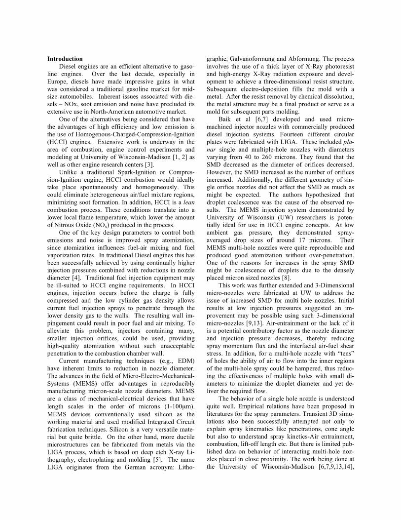
process diagram is shown in Figure 1. The process is
discussed in detail in our previous paper [9].
Figure 1 Modified LIGA Process
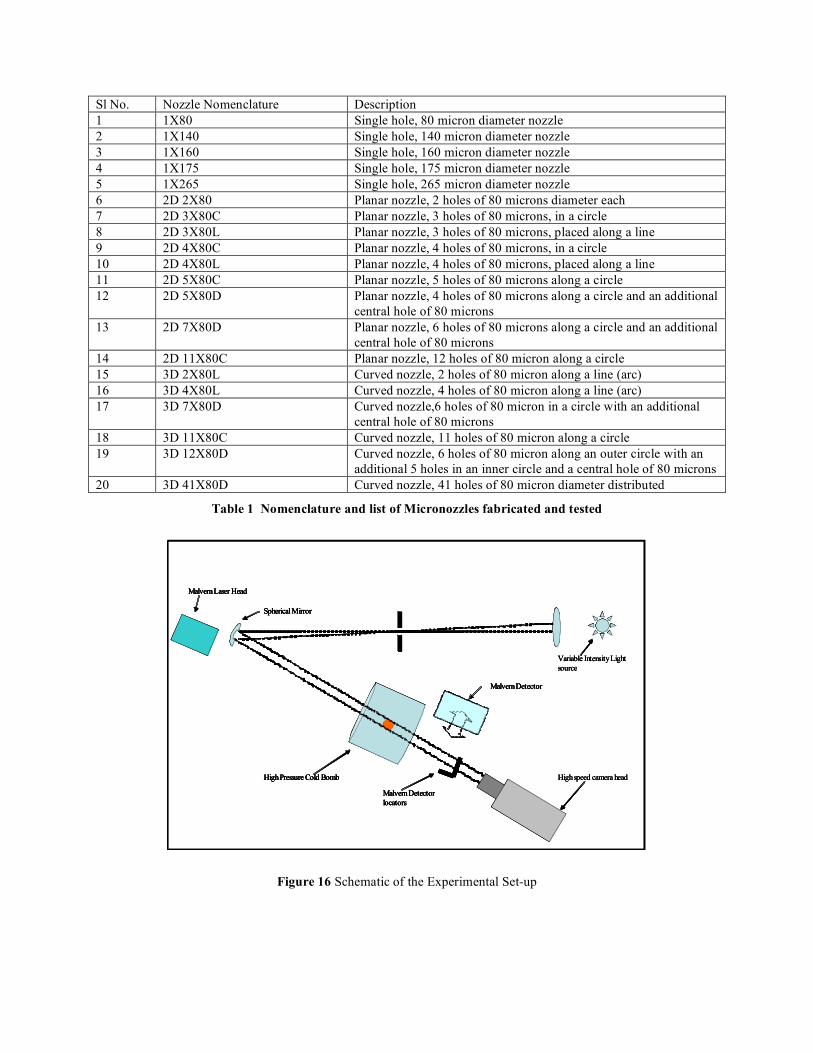
A total of 17 planar (2D) and 8 curved (3D) noz-
zles were tested at different injection pressures (up to
400bar). The outer diameter is about 2.5 mm and the
thickness varied from 200-300 microns. Table 1 at the
end of the paper lists the various nozzles fabricated and
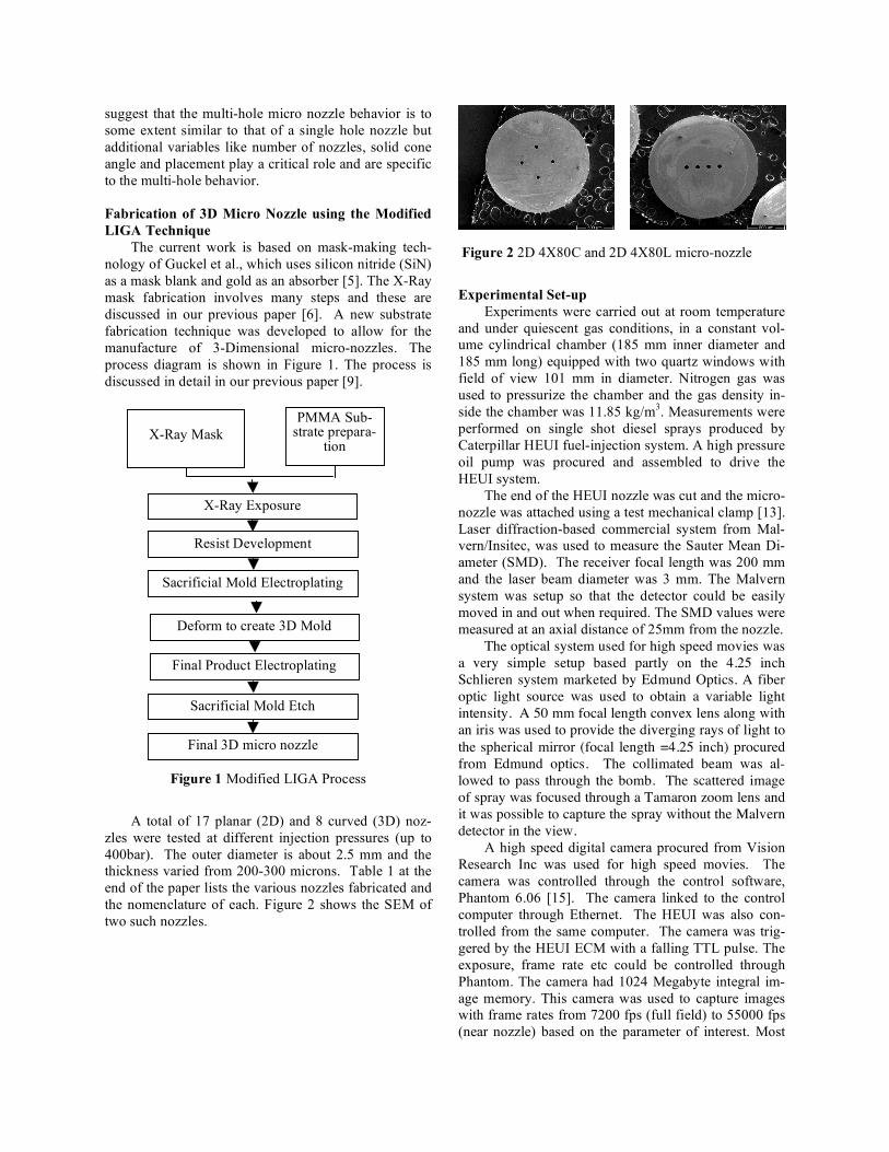
the nomenclature of each. Figure 2 shows the SEM of
two such nozzles.
Figure 2 2D 4X80C and 2D 4X80L micro-nozzle
Experimental Set-up
Experiments were carried out at room temperature
and under quiescent gas conditions, in a constant vol-
ume cylindrical chamber (185 mm inner diameter and
185 mm long) equipped with two quartz windows with
field of view 101 mm in diameter. Nitrogen gas was
used to pressurize the chamber and the gas density in-
side the chamber was 11.85 kg/m3. Measurements were
performed on single shot diesel sprays produced by
Caterpillar HEUI fuel-injection system. A high pressure
oil pump was procured and assembled to drive the
HEUI system.
The end of the HEUI nozzle was cut and the micro-
nozzle was attached using a test mechanical clamp [13].
Laser diffraction-based commercial system from Mal-
vern/Insitec, was used to measure the Sauter Mean Di-
ameter (SMD). The receiver focal length was 200 mm
and the laser beam diameter was 3 mm. The Malvern
system was setup so that the detector could be easily
moved in and out when required. The SMD values were
measured at an axial distance of 25mm from the nozzle.
The optical system used for high speed movies was
a very simple setup based partly on the 4.25 inch
Schlieren system marketed by Edmund Optics. A fiber
optic light source was used to obtain a variable light
intensity. A 50 mm focal length convex lens along with
an iris was used to provide the diverging rays of light to
the spherical mirror (focal length =4.25 inch) procured
from Edmund optics. The collimated beam was al-
lowed to pass through the bomb. The scattered image
of spray was focused through a Tamaron zoom lens and
it was possible to capture the spray without the Malvern
detector in the view.
A high speed digital camera procured from Vision
Research Inc was used for high speed movies. The
camera was controlled through the control software,
Phantom 6.06 [15]. The camera linked to the control
computer through Ethernet. The HEUI was also con-
trolled from the same computer. The camera was trig-
gered by the HEUI ECM with a falling TTL pulse. The
exposure, frame rate etc could be controlled through
Phantom. The camera had 1024 Megabyte integral im-
age memory. This camera was used to capture images
with frame rates from 7200 fps (full field) to 55000 fps
(near nozzle) based on the parameter of interest. Most
of the images were taken at 15000 fps at 256 X 512
pixel resolution. The schematic of the experimental
setup is shown in Figure 16 at the end of the paper.
Multiple sprays were observed to ensure constant
injection duration, the solenoid current duration was
adjusted till the duration (as determined by the total
number of frames where the spray was visible) was
approximately 1.5 ms. Once the duration stayed con-
stant for a fixed solenoid current duration, a single in-
jection event was recorded. The bomb was purged off
the Nitrogen and a fresh charge was filled to get the
desired back pressure. The Malvern Detector was slid
back into its locating plates and finer adjustments if
needed were done based on the background scatter sig-
nature. For a fixed Rail Pressure, Multiple spray events
were measured for duration of 3ms. The SMD values
were measured at an axial distance of 25mm from the
nozzle.
The data was saved in its raw form and as ensem-
ble average values. These data files were used for re-
sult analysis and to draw conclusions. A few measure-
ments were also taken with the multiple scattering cor-
rections turned off, to see the effect of the correction
algorithm.
Once multiple data values were recorded the detec-
tor was slid out of the view of the camera. The light
source was turned on and another movie of a single
injection event was recorded with no modifications to
the Injection system/specifications. These two movies
give a fair idea as to the extent the spray varied between
the each injection event. It also is a check that the no
abnormal injection event (leakage, pool of liquid etc)
was recorded.
Experimental Results
Single Hole Nozzle
10.00
12.00
14.00
16.00
18.00
20.00
4 4.5 5 5.5 6 6.5
Rail Pressure [MPa]
SM
D [
mic
ron
s]
1X80 1X140 1X160 1X265
Figure 3 Effect of Rail Pressure on SMD for a single
hole nozzle
10.00
15.00
20.00
25.00
4 4.5 5 5.5 6 6.5
Rail Pressure [MPa]
SM
D [
mic
ron
s]
1X80 2D11X80C 3D11X80C
Figure 4 Effect of Rail Pressure on SMD for multi-hole
nozzle
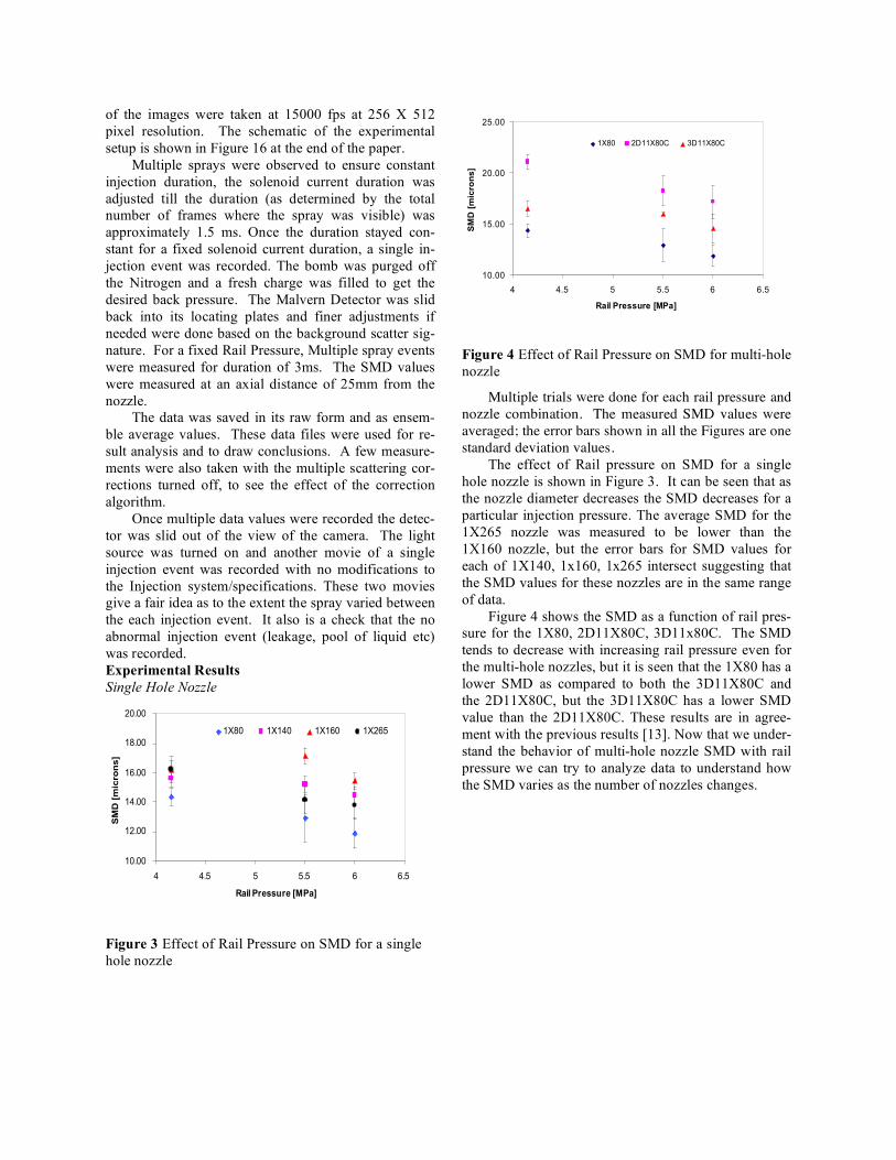
Multiple trials were done for each rail pressure and
nozzle combination. The measured SMD values were
averaged; the error bars shown in all the Figures are one
standard deviation values.
The effect of Rail pressure on SMD for a single
hole nozzle is shown in Figure 3. It can be seen that as
the nozzle diameter decreases the SMD decreases for a
particular injection pressure. The average SMD for the
1X265 nozzle was measured to be lower than the
1X160 nozzle, but the error bars for SMD values for
each of 1X140, 1x160, 1x265 intersect suggesting that
the SMD values for these nozzles are in the same range
of data.
Figure 4 shows the SMD as a function of rail pres-
sure for the 1X80, 2D11X80C, 3D11x80C. The SMD
tends to decrease with increasing rail pressure even for
the multi-hole nozzles, but it is seen that the 1X80 has a
lower SMD as compared to both the 3D11X80C and
the 2D11X80C, but the 3D11X80C has a lower SMD
value than the 2D11X80C. These results are in agree-
ment with the previous results [13]. Now that we under-
stand the behavior of multi-hole nozzle SMD with rail
pressure we can try to analyze data to understand how
the SMD varies as the number of nozzles changes.
y = 0.5577x + 14.225
R2 = 0.6188
5
10
15
20
25
0 1 2 3 4 5 6 7 8 9 10 11 12 13 14
Number of Nozzles
SM
D[m
icro
ns]
Rail Pressure = 4.15 MPa
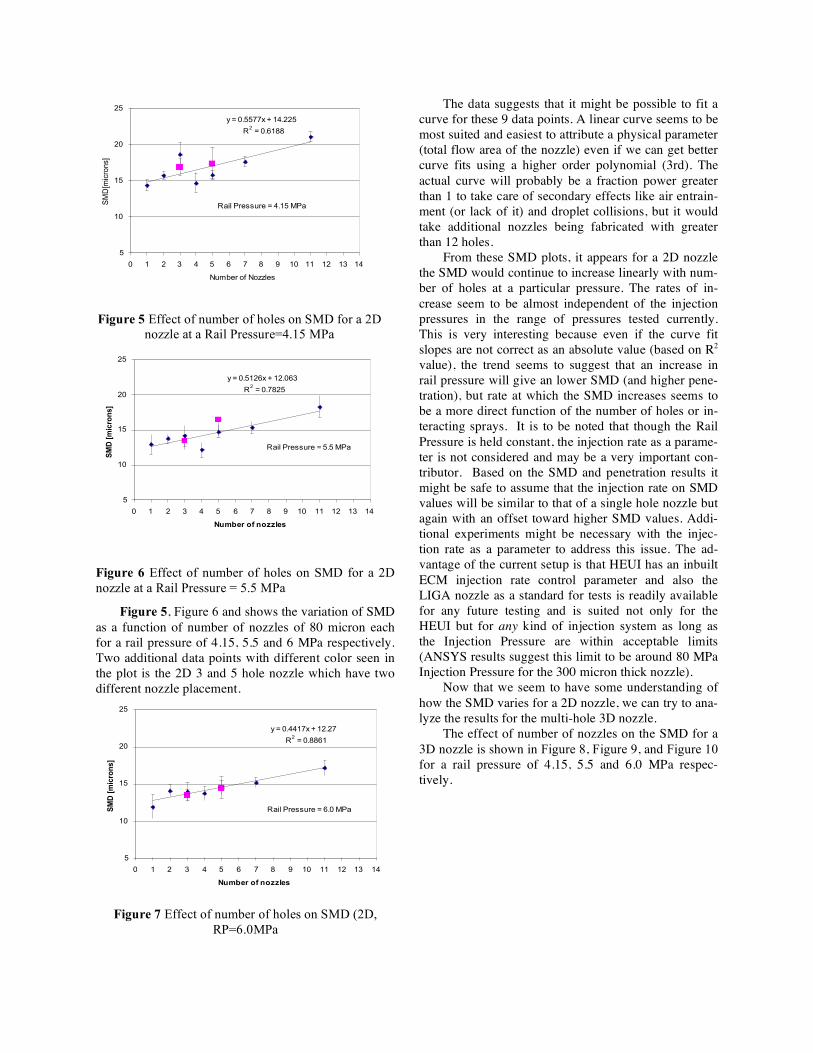
Figure 5 Effect of number of holes on SMD for a 2D
nozzle at a Rail Pressure=4.15 MPa
y = 0.5126x + 12.063
R2 = 0.7825
5
10
15
20
25
0 1 2 3 4 5 6 7 8 9 10 11 12 13 14
Number of nozzles
SM
D [
mic
ron
s]
Rail Pressure = 5.5 MPa
Figure 6 Effect of number of holes on SMD for a 2D
nozzle at a Rail Pressure = 5.5 MPa
Figure 5, Figure 6 and shows the variation of SMD
as a function of number of nozzles of 80 micron each
for a rail pressure of 4.15, 5.5 and 6 MPa respectively.
Two additional data points with different color seen in
the plot is the 2D 3 and 5 hole nozzle which have two
different nozzle placement.
y = 0.4417x + 12.27
R2 = 0.8861
5
10
15
20
25
0 1 2 3 4 5 6 7 8 9 10 11 12 13 14
Number of nozzles
SM
D [
mic
ron
s]
Rail Pressure = 6.0 MPa
Figure 7 Effect of number of holes on SMD (2D,
RP=6.0MPa
The data suggests that it might be possible to fit a
curve for these 9 data points. A linear curve seems to be
most suited and easiest to attribute a physical parameter
(total flow area of the nozzle) even if we can get better
curve fits using a higher order polynomial (3rd). The
actual curve will probably be a fraction power greater
than 1 to take care of secondary effects like air entrain-
ment (or lack of it) and droplet collisions, but it would
take additional nozzles being fabricated with greater
than 12 holes.
From these SMD plots, it appears for a 2D nozzle
the SMD would continue to increase linearly with num-
ber of holes at a particular pressure. The rates of in-
crease seem to be almost independent of the injection
pressures in the range of pressures tested currently.
This is very interesting because even if the curve fit
slopes are not correct as an absolute value (based on R2
value), the trend seems to suggest that an increase in
rail pressure will give an lower SMD (and higher pene-
tration), but rate at which the SMD increases seems to
be a more direct function of the number of holes or in-
teracting sprays. It is to be noted that though the Rail
Pressure is held constant, the injection rate as a parame-
ter is not considered and may be a very important con-
tributor. Based on the SMD and penetration results it
might be safe to assume that the injection rate on SMD
values will be similar to that of a single hole nozzle but
again with an offset toward higher SMD values. Addi-
tional experiments might be necessary with the injec-
tion rate as a parameter to address this issue. The ad-
vantage of the current setup is that HEUI has an inbuilt
ECM injection rate control parameter and also the
LIGA nozzle as a standard for tests is readily available
for any future testing and is suited not only for the
HEUI but for any kind of injection system as long as
the Injection Pressure are within acceptable limits
(ANSYS results suggest this limit to be around 80 MPa
Injection Pressure for the 300 micron thick nozzle).
Now that we seem to have some understanding of
how the SMD varies for a 2D nozzle, we can try to ana-
lyze the results for the multi-hole 3D nozzle.
The effect of number of nozzles on the SMD for a
3D nozzle is shown in Figure 8, Figure 9, and Figure 10
for a rail pressure of 4.15, 5.5 and 6.0 MPa respec-
tively.
y = 0.1175x + 15.561
R2 = 0.1751
5
10
15
20
25
0 3 6 9 12Number of nozzles
SM
D [
mic
ron
s]
Rail Pressure = 4.15 MPa
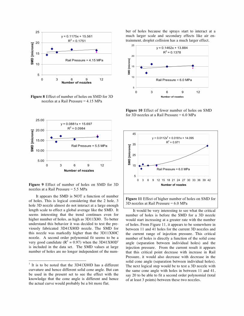
Figure 8 Effect of number of holes on SMD for 3D
nozzles at a Rail Pressure = 4.15 MPa
y = 0.0881x + 15.697
R2 = 0.0984
5.00
10.00
15.00
20.00
25.00
0 3 6 9 12
Number of nozzles
SM
D [
mic
ron
s]
Rail Pressure = 5.5 MPa
Figure 9 Effect of number of holes on SMD for 3D
nozzles at a Rail Pressure = 5.5 MPa
It appears the SMD is NOT a function of number
of holes. This is logical considering that the 2 hole, 3
hole 3D nozzle almost do not interact at a large enough
length scale to effect a global average like the SMD. It
seems interesting that the trend continues even for
higher number of holes, as high as 3D11X80. To better
understand this behavior it was decided to test the pre-
viously fabricated 3D41X80D nozzle. The SMD for
this nozzle was markedly higher than the 3D11X80C
nozzle. A second order polynomial fit seems to be a
very good candidate (R2 = 0.97) when the 3D41X80D1
is included in the data set. The SMD values at large
number of holes are no longer independent of the num-
1 It is to be noted that the 3D41X80D has a different
curvature and hence different solid cone angle. But can
be used in the present set to see the effect with the
knowledge that the cone angle is different and hence
the actual curve would probably be a bit more flat.
ber of holes because the sprays start to interact at a
much larger scale and secondary effects like air en-
trainment, droplet collision has a much larger effect.
y = 0.1462x + 13.884
R2 = 0.1378
5
10
15
20
25
0 3 6 9 12
Number of nozzles
SM
D [
mic
ron
s]
Rail Pressure = 6.0 MPa
Figure 10 Effect of fewer number of holes on SMD
for 3D nozzles at a Rail Pressure = 6.0 MPa
y = 0.0112x2 + 0.0181x + 14.095
R2 = 0.971
5
15
25
35
45
0 3 6 9 12 15 18 21 24 27 30 33 36 39 42
Number of nozzles
SM
D [
mic
ron
s]
Rail Pressure = 6.0 MPa
Figure 11 Effect of higher number of holes on SMD for
3D nozzles at Rail Pressure = 6.0 MPa
It would be very interesting to see what the critical
number of holes is before the SMD for a 3D nozzle
would start increasing at a greater rate with the number
of holes. From Figure 11, it appears to be somewhere in
between 11 and 41 holes for the current 3D nozzles and
the current range of injection pressure. This critical
number of holes is directly a function of the solid cone
angle (separation between individual holes) and the
injection pressure. From the current result it appears
that this critical point decrease with increase in Rail
Pressure, it would also decrease with decrease in the
solid cone angle (separation between individual holes).
The next logical step would be to test a 3D nozzle with
the same cone angle with holes in between 11 and 41,
say 20 to be able to fit a second order polynomial (total
of at least 3 points) between these two nozzles.
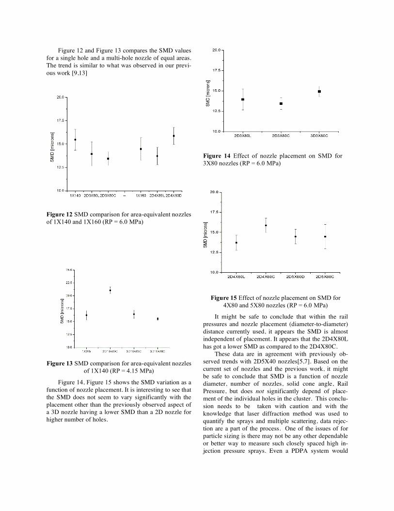
Figure 12 and Figure 13 compares the SMD values
for a single hole and a multi-hole nozzle of equal areas.
The trend is similar to what was observed in our previ-
ous work [9,13]
Figure 12 SMD comparison for area-equivalent nozzles
of 1X140 and 1X160 (RP = 6.0 MPa)
Figure 13 SMD comparison for area-equivalent nozzles
of 1X140 (RP = 4.15 MPa)
Figure 14, Figure 15 shows the SMD variation as a
function of nozzle placement. It is interesting to see that
the SMD does not seem to vary significantly with the
placement other than the previously observed aspect of
a 3D nozzle having a lower SMD than a 2D nozzle for
higher number of holes.
Figure 14 Effect of nozzle placement on SMD for
3X80 nozzles (RP = 6.0 MPa)
Figure 15 Effect of nozzle placement on SMD for
4X80 and 5X80 nozzles (RP = 6.0 MPa)
It might be safe to conclude that within the rail
pressures and nozzle placement (diameter-to-diameter)
distance currently used, it appears the SMD is almost
independent of placement. It appears that the 2D4X80L
has got a lower SMD as compared to the 2D4X80C.
These data are in agreement with previously ob-
served trends with 2D5X40 nozzles[5,7]. Based on the
current set of nozzles and the previous work, it might
be safe to conclude that SMD is a function of nozzle
diameter, number of nozzles, solid cone angle, Rail
Pressure, but does not significantly depend of place-
ment of the individual holes in the cluster. This conclu-
sion needs to be taken with caution and with the
knowledge that laser diffraction method was used to
quantify the sprays and multiple scattering, data rejec-
tion are a part of the process. One of the issues of for
particle sizing is there may not be any other dependable
or better way to measure such closely spaced high in-
jection pressure sprays. Even a PDPA system would
have a large amount of data rejection as we try to probe
near-nozzle.
Conclusions
The ability to fabricate micro-nozzles of high qual-
ity and reliability is because of the use of MEMS-LIGA
fabrication technique. Modifications to the standard
LIGA micro-fabrication technique can be successfully
used to fabricate both 2-D and 3-D micro-nozzles. The
LIGA can be attractive to other fabrication methods like
laser drilling because of the high quality nozzle cross-
section obtained. This high quality is very important
for research settings. These nozzles along with tempo-
rary clamps provide an ability to fabricate “Nozzle
Standards” to be reused and retested with different in-
jection system for baseline data.
The following conclusion can be drawn based on
the experimental results obtained
The SMD decreases as the nozzle diameter de-
creases and Injection pressure increases for a single
hole nozzle. The behavior of a Multihole nozzle is more
complex.
Multihole Planar (2D) Nozzle
The SMD values do not seem to be directly related
to nozzle placement but on number of nozzles (flow
area) suggesting that droplet collision is the controlling
mechanism rather than interfacial forces.
The SMD value seems to increase linearly with in-
crease in number of nozzles
Multihole Curved (3D) Nozzle
The SMD value for the 3D nozzles for less number
of nozzles does not seem to depend on the number of
nozzles in the present experimental conditions of rail
pressure, center-to-center distance and solid cone angle.
The SMD ramps up steeply as the number of nozzles
are increased
Highly atomized sprays with SMD in the 10µm
range are possible with a single hole micro-nozzle using
pressure in the range of 100 MPa. The current work on
micro-nozzles seems to suggest we may need a non-
traditional approach for injection rate, injection pres-
sure and hole-to-hole orientation/spacing for satisfac-
tory use for a diesel application with larger flow areas
needed in engines than single hole micro-nozzles.
References
1. Noda, T., Foster, D., A Numerical Study to Control
combustion Duration of Hydrogen-fueled HCCI by
using Multi-zone Chemical Kinetics Simulation,
SAE 2001-01-0327, 2001
2. Aroonsrisopon, T, An Experimental investigation of
homogeneous charge Compression ignition operat-
ing Range and engine Performance with Different
Fuels, M.S. Thesis, Mech Engg Dept., Univ. of
Wisconsin-Madison, 2002
3. Christensen, M., Johansson, B, Influence of Mixture
Quality on Homogeneous charge Compression Igni-
tion SAE 982454, 1998
4. Tanaka, T., et al Research Concerning Injection
Nozzle Shape for Direct-Injection Diesel Engine Us-
ing Common Rail Injection System, FISITA2002,
Helsinki, 2002
5. Guckel, H., Christenson, T, T.,Skrobis, K., Metal
Micromechanisms via Deep X-Ray Lithography,
Electroplating and Assembly, J.Micromech. Mi-
croengg. 2,1992, pp225-228
6. Baik, S., Goney, K.H., Kang, S., Murphy J.,
Blanchard, J., Corradini, M., Development of Micro-
Diesel Injector Nozzles via MEMS Technology and
Initial Results for Diesel Sprays SAE 1999-01-3645
7. Baik, S., Kang, J., Blanchard, J., Corradini, M., De-
velopment of Micro-Diesel Injector Nozzles via
MEMS Technology and Effects on Spray Character-
istics, Eight Intl. Conf. Liquid Atomization and
Spray Sys., Pasadena, CA, USA, July 2000
8. Jiang, Y.J, Umemura, A., Law, C.K., An Experi-
mental Investigation on the collision behavior of
Hydrocarbon Droplets, J. Fluid Mech. (1992), vol.
234, pp. 171-190
9. Prashanth Ravi, P., Blanchard, J., Corradini, M.,
Diesel Spray Behavior with 3-Dimensional Micro-
Nozzles, Ninth Intl. Conf. Liquid Atomization and
Spray Sys., Sorrento, Italy, Sept 2003.
10. Siebers, D., Higgins, B., Flame Lift-Off on Direct-
Injection Diesel Sprays under Quiescent Conditions,
SAE2001-01-0530, 2001
11. Siebers, D., Pickett L., Flame Lift-Off on Direct-
Injection Diesel Fuel Jets: Oxygen Concentration
Effects, SAE2002-01-0890,2002
12. Maus, F.S., MEMS Micro-Nozzle Material-Joining
Studies, MS Thesis, Mech Engg Dept., Univ. of
Wisc-Madison, 2003
13. Prashanth Ravi, et al, 3-Dimensional & 2-
Dimensional Micro-Orifice Spray Nozzles:Method
of Attachment and its effect on Diesel Spray Behav-
ior, ILASS 2004, Arlington, VA
14. Prashanth Ravi, Diesel Spray through Multi-hole
Micronozzles, PhD Thesis, Mech Engg Dept., Univ
of Wisconsin-Madison, 2005
15. Phantom 6.06 Operating Manual from Vision Re-
search Inc.
Sl No. Nozzle Nomenclature Description
1 1X80 Single hole, 80 micron diameter nozzle
2 1X140 Single hole, 140 micron diameter nozzle
3 1X160 Single hole, 160 micron diameter nozzle
4 1X175 Single hole, 175 micron diameter nozzle
5 1X265 Single hole, 265 micron diameter nozzle
6 2D 2X80 Planar nozzle, 2 holes of 80 microns diameter each
7 2D 3X80C Planar nozzle, 3 holes of 80 microns, in a circle
8 2D 3X80L Planar nozzle, 3 holes of 80 microns, placed along a line
9 2D 4X80C Planar nozzle, 4 holes of 80 microns, in a circle
10 2D 4X80L Planar nozzle, 4 holes of 80 microns, placed along a line
11 2D 5X80C Planar nozzle, 5 holes of 80 microns along a circle
12 2D 5X80D Planar nozzle, 4 holes of 80 microns along a circle and an additional
central hole of 80 microns
13 2D 7X80D Planar nozzle, 6 holes of 80 microns along a circle and an additional
central hole of 80 microns
14 2D 11X80C Planar nozzle, 12 holes of 80 micron along a circle
15 3D 2X80L Curved nozzle, 2 holes of 80 micron along a line (arc)
16 3D 4X80L Curved nozzle, 4 holes of 80 micron along a line (arc)
17 3D 7X80D Curved nozzle,6 holes of 80 micron in a circle with an additional
central hole of 80 microns
18 3D 11X80C Curved nozzle, 11 holes of 80 micron along a circle
19 3D 12X80D Curved nozzle, 6 holes of 80 micron along an outer circle with an
additional 5 holes in an inner circle and a central hole of 80 microns
20 3D 41X80D Curved nozzle, 41 holes of 80 micron diameter distributed
Table 1 Nomenclature and list of Micronozzles fabricated and tested
Variable Intensity Light
source
High speed camera head
Malvern Laser Head
Spherical Mirror
High Pressure Cold Bomb
Malvern Detector
Malvern Detector
locators
Variable Intensity Light
source
High speed camera head
Malvern Laser Head
Spherical Mirror
High Pressure Cold Bomb
Malvern Detector
Malvern Detector
locators
Variable Intensity Light
source
High speed camera head
Malvern Laser Head
Spherical Mirror
High Pressure Cold Bomb
Malvern Detector
Malvern Detector
locators
Malvern Laser Head
Spherical Mirror
High Pressure Cold Bomb
Malvern Detector
Malvern Detector
locators
Figure 16 Schematic of the Experimental Set-up