Embed Size (px)
Citation preview
Ford Customer Service DivisionTechnical Training
Diesel EnginePerformance
Diagnosis
Student Guide
FCS-14573-REF
Course Code: 51S08T1
June, 2006
51 - Diesel Engine Performance

Blank
IMPORTANT SAFETY NOTICE
Appropriate service methods and proper repair procedures are essential for the safe, reliable operation of all motor vehicles,as well as the personal safety of the individual doing the work. This manual provides general directions for accomplishingservice and repair work with tested, effective techniques. Following them will help assure reliability.
There are numerous variations in procedures, techniques, tools and parts for servicing vehicles, as well as in the skill of theindividual doing the work. This manual cannot possibly anticipate all such variations and provide advice or cautions as to each.Accordingly, anyone who departs from instructions provided in this manual must first establish that he compromises neitherhis personal safety nor the vehicle integrity by his choice of methods, tools or parts.
As you read through the procedures, you will come across NOTES, CAUTIONS, and WARNINGS. Each one is there for aspecific purpose. NOTES give you added information that will help you to complete a particular procedure. CAUTIONS aregiven to prevent you from making an error that could damage the vehicle. WARNINGS remind you to be especially carefulin those areas where carelessness can cause personal injury. The following list contains some general WARNINGS that youshould follow when you work on a vehicle.
Always wear safety glasses for eye protection.
Use safety stands whenever a procedure requires youto be under the vehicle.
Be sure that the ignition switch is always in the OFFposition, unless otherwise required by the procedure.
Set the parking brake when working on the vehicle. If youhave an automatic transmission, set it in PARK unlessinstructed otherwise for a specific service operation. Ifyou have a manual transmission it should be in REVERSE(engine OFF) or NEUTRAL (engine ON) unless instructedotherwise for a specific service operation.
Operate the engine only in a well-ventilated area to avoidthe danger of carbon monoxide.
Keep yourself and your clothing away from moving partswhen the engine is running, especially the fan and belts.
To help prevent serious burns, avoid contact with hotmetal parts such as the radiator, exhaust manifold, tailpipe, catalytic converter and muffler.
Do not smoke while working on the vehicle.
To help avoid injury, always remove rings, watches,loose hanging jewelry, and loose clothing before begin-ning to work on a vehicle. Tie long hair securely behindyour head.
Keep hands and other objects clear of the radiator fanblades. Electric cooling fans can start to operate at anytime by an increase in underhood temperatures, eventhough the ignition is in the OFF position. Therefore,care should be taken to ensure that the electric coolingfan is completely disconnected when working under thehood.
The recommendations and suggestions contained in this manual are made to assist the dealer in improving his dealership partsand/or service department operations. These recommendations and suggestions do not supersede or override the provisions ofthe Warranty and Policy Manual, and in any cases where there may be a conflict, the provisions of the Warranty and Policy Manualshall govern.
The descriptions, testing procedures, and specifications in this handbook were in effect at the time the handbook wasapproved for printing. Ford Motor Company reserves the right to discontinue models at any time, or change specifications,design, or testing procedures without notice and without incurring obligation. Any reference to brand names in this manualis intended merely as an example of the types of tools, lubricants, materials, etc. recommended for use. Equivalents, ifavailable, may be used. The right is reserved to make changes at any time without notice.
DANGER: Exposure to potentially hazardous components may occur if dusts are created during repair of friction compo-nents, such as brake pads and clutch discs. Exposure to excessive amounts of dust may be a potential cancer and lung diseasehazard. Exposure may also cause irritation to skin, eyes, and respiratory tract, may cause allergic reactions, and/or may lead to otherchronic health effects.
Do not breathe dust. Do not use compressed air to blow dust from storage containers or friction components. A high-efficiency(HEPA) vacuum cleaner should be used carefully to remove dust. Adherent dust should be removed with a damp rag.
If inhaled, remove to fresh air. If irritation persists, seek medical attention or advice.
If dust gets in eyes, irrigate under eyelids with water for 15 minutes and seek medical attention.
Copyright © 2006 Ford Motor Company Produced and Coodinated byTechnical Support OperationsFord Customer Service Division
June, 2006
CUSTOMER EXPECTATIONSM
Customer Expectations: Service1. Make it convenient to have my vehicle
serviced at your dealership.
2. The Service Advisor should demonstratea genuine concern for my service needs.
3. Fix it right the first time, on time.
4. Complete servicing my vehicle in atimely and professional manner.
5. Provide me with a clear and thoroughexplanation of the service performed.
6. Call me within a reasonable amount oftime after my service visit to ensure thatI'm completely satisfied.
7. Be responsive to questions or concernsthat I bring to your attention.
Expectation #3
“Fix It Right the First Time, on Time.”Both service advisors and technicians are important players when it comes to Expectation #3.
WhyCustomers tell us “Fixing It Right the First Time, on Time” is one of the reasons they woulddecide to return to a dealer to buy a vehicle and get their vehicles serviced.
Technician TrainingIt is our goal to help the technician acquire all of the skills and knowledge necessary to“Fix it Right the First Time, on Time.” We refer to this as “competency.”
Technician’s RoleAcquire the skills and knowledge for competency in your specialty via:
STST New Model— Web-Based — Web-Based— Instructor Led — Instructor Led
The BenefitsThe successful implementation of expectations means:
— Satisfied customers— Repeat vehicle sales— Repeat service sales— Recognition that Ford and Lincoln/Mercury technicians are “the Best in the Business”
DIESEL ENGINE PERFORMANCE DIAGNOSIS TABLE OF CONTENTS
Diesel Engine Performance Diagnosis TOC - i June, 2006
INTRODUCTION ............................................................................................................. Intro - 1Ford Diesel Engine Performance Diagnosis .............................................................................. Intro - 2
Course Description ............................................................................................................. Intro - 2Worksheets ......................................................................................................................... Intro - 2Course Requirements ......................................................................................................... Intro - 3Course Objectives .............................................................................................................. Intro - 3Course Agenda ................................................................................................................... Intro - 3
LESSON ONE PREREQUISITE REVIEW ............................................................................ 1 - 1Prerequisite Review ....................................................................................................................... 1 - 2Fuel Injection ................................................................................................................................. 1 - 9
Fuel Injectors ........................................................................................................................... 1 - 9Injector Coils .......................................................................................................................... 1 - 10Spool Valve ............................................................................................................................ 1 - 10Intensifier Piston .................................................................................................................... 1 - 10O-Rings ................................................................................................................................. 1 - 10Hydraulic Electronic Unit Injector (HEUI) Operation ................................................................1 - 11Plunger and Barrel ..................................................................................................................1 - 11Injection Nozzle .......................................................................................................................1 - 11Three Stages of Injection ....................................................................................................... 1 - 12
High Pressure Oil System ............................................................................................................ 1 - 13High Pressure Pump .............................................................................................................. 1 - 14Injection Pressure Regulator (IPR) Valve ............................................................................... 1 - 15
Air Management System .............................................................................................................. 1 - 16Air Management System Flow ................................................................................................ 1 - 16Air Filter/Filter Minder ............................................................................................................. 1 - 17
Air Management Inputs ................................................................................................................ 1 - 17Exhaust Pressure (EP) Sensor .............................................................................................. 1 - 17Mass Air Flow (MAF) Sensor .................................................................................................. 1 - 17Intake Air Temperature (IAT) Sensor ...................................................................................... 1 - 17Intake Air Temperature 2 (IAT2) Sensor .................................................................................. 1 - 17Manifold Absolute Pressure (MAP) Sensor ............................................................................ 1 - 17Barometric Pressure (BP) Sensor .......................................................................................... 1 - 17
Air Management Outputs ............................................................................................................. 1 - 18Turbocharger System............................................................................................................. 1 - 18Exhaust Gas Recirculation (EGR) System ............................................................................. 1 - 19EGR Valve ............................................................................................................................. 1 - 19EGR Throttle Valve ................................................................................................................ 1 - 20EGR Cooler ........................................................................................................................... 1 - 21EGR System PID Data ........................................................................................................... 1 - 22
LESSON ONE WORKSTATIONS ...................................................................................... 1 - 23Summary...................................................................................................................................... 1 - 23WORKSTATION 1: SERVICE PUBLICATIONS NAVIGATION ...................................................... 1 - 24WORKSTATION 2: ON-VEHICLE PID SELECTION, RECORDING AND ANALYSIS USING WDS/IDS ...................................................................................................................... 1 - 27WORKSTATION 3: WDS PID DATA ANALYSIS - 6.0L DIESEL SENSOR VALUE COMPARISON .......................................................................................................................... 1 - 30WORKSTATION 4: HIGH PRESSURE OIL PUMP SERVICE ON 6.0L ENGINE .......................... 1 - 37
DIESEL ENGINE PERFORMANCE DIAGNOSIS TABLE OF CONTENTS
Diesel Engine Performance Diagnosis TOC - ii June, 2006
LESSON TWO WORKSTATIONS....................................................................................................... 2 - 1Summary........................................................................................................................................ 2 - 1WORKSTATION 1: POOR PERFORMANCE/LACK OF POWER DIAGNOSIS USING PID DATA ANALYSIS ................................................................................................................... 2 - 2WORKSTATION 2: NO START DIAGNOSIS ON-VEHICLE ........................................................... 2 - 4WORKSTATION 3: LACK OF POWER DIAGNOSIS IN “VIRTUAL SHOP”..................................... 2 - 6WORKSTATION 4: LEAK POINT IDENTIFICATION/ROCKER ARM SERVICE ON 6.0L ENGINE ...................................................................................................................................... 2 - 8
LESSON THREE WORKSTATIONS ................................................................................................... 3 - 1Summary........................................................................................................................................ 3 - 1WORKSTATION 1: LACK OF POWER DIAGNOSIS USING PID DATA ANALYSIS ........................ 3 - 2WORKSTATION 2: LACK OF POWER DIAGNOSIS ON-VEHICLE ................................................ 3 - 4WORKSTATION 3: RUNS ROUGH DIAGNOSIS USING PID DATA ANALYSIS ............................. 3 - 6WORKSTATION 4: HIGH PRESSURE OIL SYSTEM DIAGNOSIS ON 6.0L ENGINE .................... 3 - 7
LESSON FOUR WORKSTATIONS ..................................................................................................... 4 - 1Summary........................................................................................................................................ 4 - 1WORKSTATION 1: LACK OF POWER DIAGNOSIS USING PID DATA ANALYSIS ........................ 4 - 2WORKSTATION 2: LACK OF POWER DIAGNOSIS ON-VEHICLE ................................................ 4 - 3WORKSTATION 3: CRANKS/NO START DIAGNOSIS IN “VIRTUAL SHOP” ................................ 4 - 5WORKSTATION 4: FUEL INJECTOR SERVICE AND INSPECTION ON 6.0L ENGINE ................. 4 - 7
APPENDIX .............................................................................................................................. Appendix - 1Glossary of Acronyms ........................................................................................................ Appendix - 1Complete Recommended 6.0L PowerStroke® Diesel PID List ............................................ Appendix - 36.0L PowerStroke® Diesel PID List .................................................................................... Appendix - 4Special Tools Used in This Course .................................................................................... Appendix - 5
DIESEL ENGINE PERFORMANCE DIAGNOSIS INTRODUCTION
Diesel Engine Performance Diagnosis Intro - 1 June, 2006
INTRODUCTION
DIESEL ENGINE PERFORMANCE DIAGNOSIS INTRODUCTION
Diesel Engine Performance Diagnosis Intro - 2 June, 2006
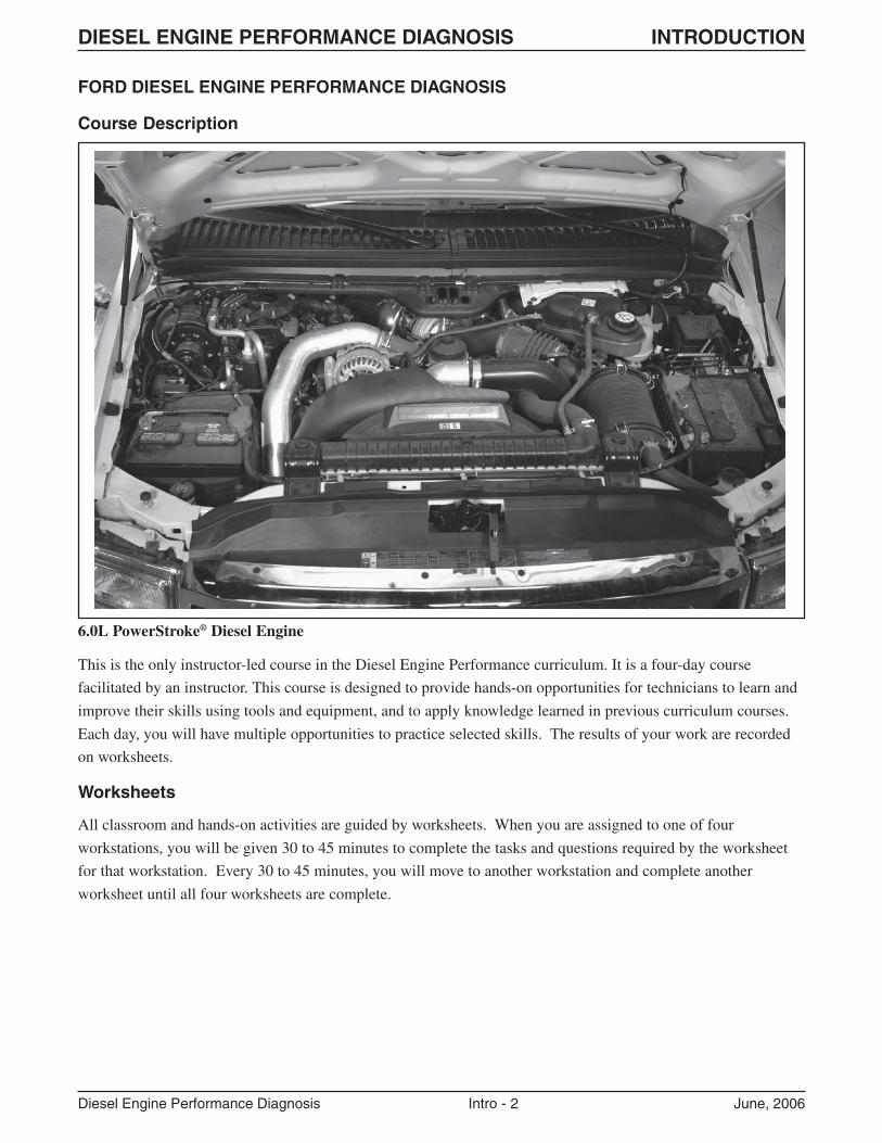
This is the only instructor-led course in the Diesel Engine Performance curriculum. It is a four-day course
facilitated by an instructor. This course is designed to provide hands-on opportunities for technicians to learn and
improve their skills using tools and equipment, and to apply knowledge learned in previous curriculum courses.
Each day, you will have multiple opportunities to practice selected skills. The results of your work are recorded
on worksheets.
Worksheets
All classroom and hands-on activities are guided by worksheets. When you are assigned to one of four
workstations, you will be given 30 to 45 minutes to complete the tasks and questions required by the worksheet
for that workstation. Every 30 to 45 minutes, you will move to another workstation and complete another
worksheet until all four worksheets are complete.
FORD DIESEL ENGINE PERFORMANCE DIAGNOSIS
Course Description
6.0L PowerStroke® Diesel Engine
DIESEL ENGINE PERFORMANCE DIAGNOSIS INTRODUCTION
Diesel Engine Performance Diagnosis Intro - 3 June, 2006
Course Requirements
Each technician attending this course will be required to pass a combination of hands-on and written evaluations.
These will be administered after Lesson 4.
� The hands-on evaluation is a pass/fail type. It will be conducted with exercises in diesel engine performancediagnosis, and will cover:
– diesel performance system diagnosis
– service publication navigation
– selected special tool usage
In order to pass the course, you must demonstrate mastery of the skills covered at the evaluated hands-on exercise
AND you must answer at least 80% of the written post-test questions correctly.
Course Objectives
Upon successful completion of this course, you will be able to:
� Diagnose selected coded, non-coded and intermittent 6.0L PowerStroke® diesel engine performance concerns.
� Set up a PID list, record PIDs and review/analyze PID data related to 6.0L PowerStroke® diesel engineperformance concerns.
� Perform tests to verify and pinpoint air leaks, pre-turbo exhaust leaks, fuel leaks, high-pressure oil leaks andcombustion leaks into the fuel system on a 6.0L PowerStroke® diesel engine.
� Service the high-pressure oil system and fuel injectors by disassembly and assembly of the top-end of a 6.0LPowerStroke® diesel engine.
� Perform visual inspections and selected tests on various components to verify failures.
Course Agenda
LESSON ONE:
Introductions, Prerequisite Review, Lesson 1 Workstations (Service Publications Navigation, On-Vehicle, PID
Data Analysis and Engine Stand)
LESSON TWO:
Lesson 1 Workstation Reviews, Lesson 2 Workstations (PID Data Analysis, On-Vehicle, CMT and Engine Stand)
LESSON THREE:
Lesson 2 Workstation Reviews, Lesson 3 Workstations (PID Data Analysis [2], On-Vehicle and Engine Stand)
LESSON FOUR:
Lesson 3 Workstation Reviews, Lesson 4 Workstations (PID Data Analysis, On-Vehicle, CMT and Engine Stand),
Final Review, Post-Test
DIESEL ENGINE PERFORMANCE DIAGNOSIS INTRODUCTION
Diesel Engine Performance Diagnosis Intro - 4 June, 2006
NOTES:

LESSON ONE PREREQUISITE REVIEW
Diesel Engine Performance Diagnosis 1 - 1 June, 2006
LESSON ONE
LESSON ONE PREREQUISITE REVIEW
Diesel Engine Performance Diagnosis 1 - 2 June, 2006
PREREQUISITE REVIEW
DIRECTIONS: Answer the following diesel engine performance questions. These will be reviewed in class.
1. What three basic elements are required for a diesel engine to start?
_______________________________________________________________________________________
_______________________________________________________________________________________
_______________________________________________________________________________________
_______________________________________________________________________________________
_______________________________________________________________________________________
2. What are some characteristics essential to diesel fuel?
_______________________________________________________________________________________
_______________________________________________________________________________________
_______________________________________________________________________________________
_______________________________________________________________________________________
_______________________________________________________________________________________
3. What is the function of glow plugs?
A. To heat the air in the intake tube.
B. To heat the engine coolant.
C. To ignite the air/fuel mixture.
D. To heat the air in the combustion chambers.
LESSON ONE PREREQUISITE REVIEW
Diesel Engine Performance Diagnosis 1 - 3 June, 2006
4. What causes the sound that is characteristic of diesel engines?
_______________________________________________________________________________________
_______________________________________________________________________________________
_______________________________________________________________________________________
_______________________________________________________________________________________
_______________________________________________________________________________________
5. Why does a diesel engine produce more torque than a gasoline engine?
A. Diesel fuel burns hotter than gasoline.
B. Diesel fuel burns throughout most of the power stroke.
C. The piston travels farther in a diesel engine.
D. Diesel engines have a larger cubic inch displacement.
6. Where is the fuel heater located (if equipped)? Why is a fuel heater used on some diesel applications?
_______________________________________________________________________________________
_______________________________________________________________________________________
_______________________________________________________________________________________
_______________________________________________________________________________________
_______________________________________________________________________________________
LESSON ONE PREREQUISITE REVIEW
Diesel Engine Performance Diagnosis 1 - 4 June, 2006
7. Where is the fuel pressure regulator located on a 6.0L PowerStroke® diesel engine?
_______________________________________________________________________________________
_______________________________________________________________________________________
_______________________________________________________________________________________
8. What causes excessive white smoke from the exhaust?
_______________________________________________________________________________________
_______________________________________________________________________________________
9. What causes excessive black smoke from the exhaust?
_______________________________________________________________________________________
_______________________________________________________________________________________
10. How can engine maintenance affect engine performance?
_______________________________________________________________________________________
_______________________________________________________________________________________
_______________________________________________________________________________________
_______________________________________________________________________________________
_______________________________________________________________________________________
_______________________________________________________________________________________
_______________________________________________________________________________________
_______________________________________________________________________________________
_______________________________________________________________________________________
11. What type of sensor is the crankshaft position (CKP) sensor and how is its signal used?
_______________________________________________________________________________________
_______________________________________________________________________________________
_______________________________________________________________________________________
_______________________________________________________________________________________
LESSON ONE PREREQUISITE REVIEW
Diesel Engine Performance Diagnosis 1 - 5 June, 2006
12. What two modules work together to control fuel delivery on a 6.0L PowerStroke® diesel engine? How dothese two modules work together on this engine?
_______________________________________________________________________________________
_______________________________________________________________________________________
_______________________________________________________________________________________
_______________________________________________________________________________________
_______________________________________________________________________________________
_______________________________________________________________________________________
13. What is the function of the Charge Air Cooler (CAC)?
A. To lower the temperature of incoming air charge before it enters the cylinders.
B. To lower the temperature of the exhaust before it enters the catalytic converter.
C. To lower the temperature of the exhaust before it enters the turbocharger.
D. None of the above.
LESSON ONE PREREQUISITE REVIEW
Diesel Engine Performance Diagnosis 1 - 6 June, 2006
14. How is the high pressure oil system controlled?
_______________________________________________________________________________________
_______________________________________________________________________________________
_______________________________________________________________________________________
15. What are some unique features and benefits of the Variable Geometry Turbocharger (VGT) used on 6.0LPowerStroke® diesel engines?
_______________________________________________________________________________________
_______________________________________________________________________________________
_______________________________________________________________________________________
_______________________________________________________________________________________
16. How is exhaust backpressure controlled on a 6.0L PowerStroke® diesel engine?
_______________________________________________________________________________________
_______________________________________________________________________________________
_______________________________________________________________________________________
_______________________________________________________________________________________
_______________________________________________________________________________________
LESSON ONE PREREQUISITE REVIEW
Diesel Engine Performance Diagnosis 1 - 7 June, 2006
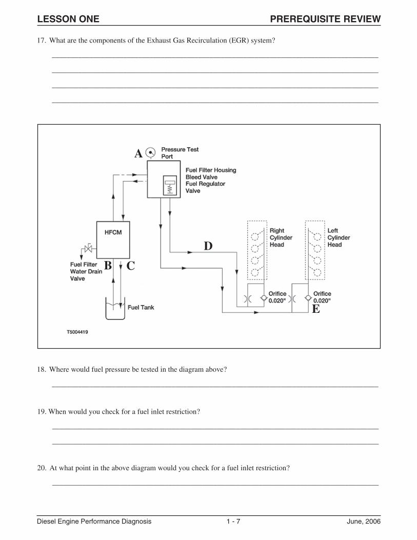
18. Where would fuel pressure be tested in the diagram above?
_______________________________________________________________________________________
A
B
E
D
C
19. When would you check for a fuel inlet restriction?
_______________________________________________________________________________________
_______________________________________________________________________________________
20. At what point in the above diagram would you check for a fuel inlet restriction?
_______________________________________________________________________________________
17. What are the components of the Exhaust Gas Recirculation (EGR) system?
_______________________________________________________________________________________
_______________________________________________________________________________________
_______________________________________________________________________________________
_______________________________________________________________________________________
LESSON ONE PREREQUISITE REVIEW
Diesel Engine Performance Diagnosis 1 - 8 June, 2006
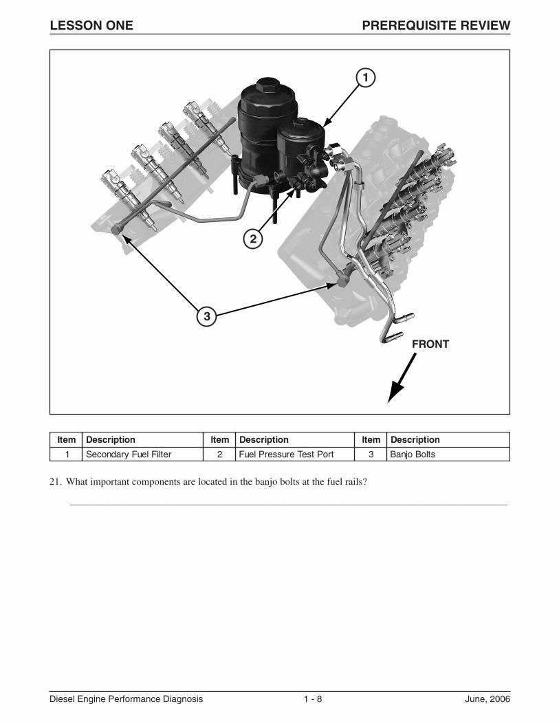
21. What important components are located in the banjo bolts at the fuel rails?
_______________________________________________________________________________________
FRONT
1
2
3
metI noitpircseD metI noitpircseD metI noitpircseD
1 retliFleuFyradnoceS 2 troPtseTerusserPleuF 3 stloBojnaB
LESSON ONE PREREQUISITE REVIEW
Diesel Engine Performance Diagnosis 1 - 9 June, 2006
FUEL INJECTION
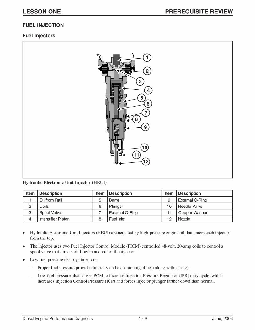
Fuel Injectors
Hydraulic Electronic Unit Injector (HEUI)
� Hydraulic Electronic Unit Injectors (HEUI) are actuated by high-pressure engine oil that enters each injectorfrom the top.
� The injector uses two Fuel Injector Control Module (FICM) controlled 48-volt, 20-amp coils to control aspool valve that directs oil flow in and out of the injector.
� Low fuel pressure destroys injectors.
– Proper fuel pressure provides lubricity and a cushioning effect (along with spring).
– Low fuel pressure also causes PCM to increase Injection Pressure Regulator (IPR) duty cycle, whichincreases Injection Control Pressure (ICP) and forces injector plunger farther down than normal.
1
2
3
4
56
78
9
10
1211
metI noitpircseD metI noitpircseD metI noitpircseD
1 liaRmorfliO 5 lerraB 9 gniR-OlanretxE
2 slioC 6 regnulP 01 evlaVeldeeN
3 evlaVloopS 7 gniR-OlanretxE 11 rehsaWreppoC
4 notsiPreifisnetnI 8 telnIleuF 21 elzzoN
LESSON ONE PREREQUISITE REVIEW
Diesel Engine Performance Diagnosis 1 - 10 June, 2006
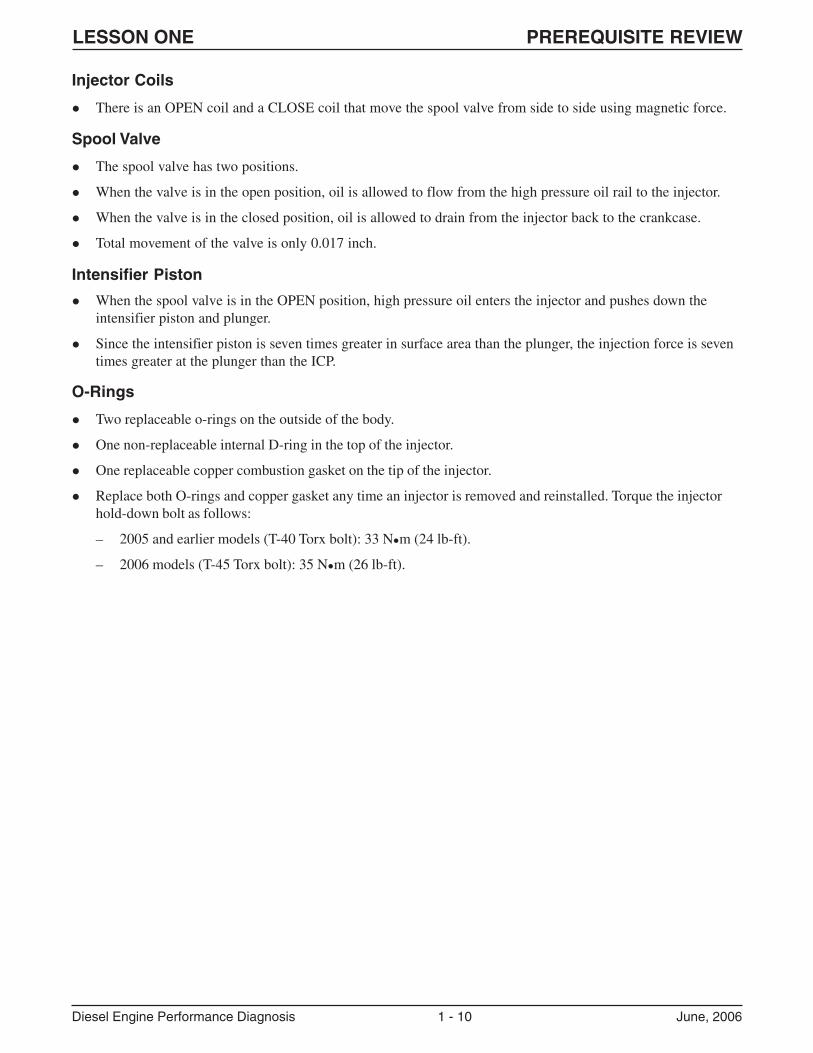
� When the spool valve is in the OPEN position, high pressure oil enters the injector and pushes down theintensifier piston and plunger.
� Since the intensifier piston is seven times greater in surface area than the plunger, the injection force is seventimes greater at the plunger than the ICP.
Injector Coils
� There is an OPEN coil and a CLOSE coil that move the spool valve from side to side using magnetic force.
Spool Valve
� The spool valve has two positions.
� When the valve is in the open position, oil is allowed to flow from the high pressure oil rail to the injector.
� When the valve is in the closed position, oil is allowed to drain from the injector back to the crankcase.
� Total movement of the valve is only 0.017 inch.
Intensifier Piston
O-Rings
� Two replaceable o-rings on the outside of the body.
� One non-replaceable internal D-ring in the top of the injector.
� One replaceable copper combustion gasket on the tip of the injector.
� Replace both O-rings and copper gasket any time an injector is removed and reinstalled. Torque the injectorhold-down bolt as follows:
– 2005 and earlier models (T-40 Torx bolt): 33 N�m (24 lb-ft).
– 2006 models (T-45 Torx bolt): 35 N�m (26 lb-ft).
LESSON ONE PREREQUISITE REVIEW
Diesel Engine Performance Diagnosis 1 - 11 June, 2006
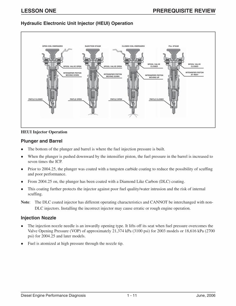
Hydraulic Electronic Unit Injector (HEUI) Operation
HEUI Injector Operation
Plunger and Barrel
� The bottom of the plunger and barrel is where the fuel injection pressure is built.
� When the plunger is pushed downward by the intensifier piston, the fuel pressure in the barrel is increased toseven times the ICP.
� Prior to 2004.25, the plunger was coated with a tungsten carbide coating to reduce the possibility of scuffingand poor performance.
� From 2004.25 on, the plunger has been coated with a Diamond Like Carbon (DLC) coating.
� This coating further protects the injector against poor fuel quality/water intrusion and the risk of internalscuffing.
Note: The DLC coated injector has different operating characteristics and CANNOT be interchanged with non-
DLC injectors. Installing the incorrect injector may cause erratic or rough engine operation.
Injection Nozzle
� The injection nozzle needle is an inwardly opening type. It lifts off its seat when fuel pressure overcomes theValve Opening Pressure (VOP) of approximately 21,374 kPa (3100 psi) for 2003 models or 18,616 kPa (2700psi) for 2004.25 and later models.
� Fuel is atomized at high pressure through the nozzle tip.
SPOOL VALVE OPEN
OPEN COIL ENERGIZED INJECTION STAGE CLOSED COIL ENERGIZED
PINTLE CLOSED
INTENSIFIER PISTONMOVING DOWN
SPOOL VALVE OPEN
INTENSIFIER PISTONMOVING DOWN
PINTLE OPEN
SPOOL VALVE CLOSED
SPOOL VALVE CLOSED
INTENSIFIER PISTONMOVING UP
PINTLE OPEN
FILL STAGE
INTENSIFIER PISTONAT REST
PINTLE CLOSED
LESSON ONE PREREQUISITE REVIEW
Diesel Engine Performance Diagnosis 1 - 12 June, 2006
Three Stages of Injection
� Fill Cycle
� Main Injection (2 steps)
� End of Main Injection (2 steps)
Fill Cycle
� During the fill stage, the spool valve is in the closed position.
� High pressure oil from the oil rail is dead headed at the spool valve.
� Low pressure fuel fills the port below the plunger.
� The needle control spring holds the needle on its seat so fuel cannot enter the combustion chamber.
Main Injection
� Pulse-width controlled current energizes the OPEN coil and magnetic force moves the spool valve to the openposition.
� High pressure oil flows past the spool valve into the intensifier piston chamber.
� Oil pressure overcomes the intensifier piston spring force and the intensifier starts to move.
� The fuel inlet check ball seats due to an increase of fuel pressure under the plunger.
� Fuel pressure starts to build.
� Force on the nozzle needle begins to build.
� When fuel pressure rises above the VOP, the nozzle needle lifts off its seat and injection begins.
End of Main Injection
� When the FICM determines that the correct injector ON time has been reached (the correct amount of fuel hasbeen delivered), it sends a pulse-width controlled current to the CLOSE coil of the injector.
� The current energizes the CLOSE coil and magnetic force pulls the spool valve to the closed position.
� High pressure oil is dead headed against the spool valve.
� Oil above the intensifier piston flows past the spool valve through the drain ports.
� As pressure is released, the intensifier piston and plunger begin to return to their initial position.
� Fuel pressure decreases until the nozzle needle control spring forces the needle back onto its seat.
LESSON ONE PREREQUISITE REVIEW
Diesel Engine Performance Diagnosis 1 - 13 June, 2006
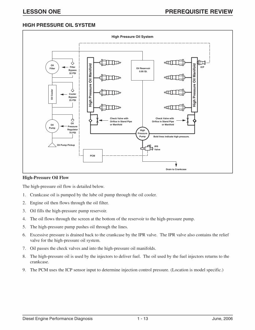
HIGH PRESSURE OIL SYSTEM
High-Pressure Oil Flow
The high-pressure oil flow is detailed below.
1. Crankcase oil is pumped by the lube oil pump through the oil cooler.
2. Engine oil then flows through the oil filter.
3. Oil fills the high-pressure pump reservoir.
4. The oil flows through the screen at the bottom of the reservoir to the high-pressure pump.
5. The high-pressure pump pushes oil through the lines.
6. Excessive pressure is drained back to the crankcase by the IPR valve. The IPR valve also contains the reliefvalve for the high-pressure oil system.
7. Oil passes the check valves and into the high-pressure oil manifolds.
8. The high-pressure oil is used by the injectors to deliver fuel. The oil used by the fuel injectors returns to thecrankcase.
9. The PCM uses the ICP sensor input to determine injection control pressure. (Location is model specific.)
OilFilter
OilPump
Oil Pump Pickup
ICP
IPRValve
PCM
Oil
Co
ole
r
Hig
h P
ress
ure
Oil
Man
ifo
ld
Hig
h P
ress
ure
Oil
Man
ifo
ld
FilterBypass32 PSI
Oil Reservoir0.95 Qt.
CoolerBypass25 PSI
HighPressure
Pump
Check Valve withOrifice in Stand Pipeor Manifold
Check Valve withOrifice in Stand Pipe
or Manifold
Drain to Crankcase
Bold lines indicate high pressure.
High Pressure Oil System
Oil PressureRegulator
70 PSI
LESSON ONE PREREQUISITE REVIEW
Diesel Engine Performance Diagnosis 1 - 14 June, 2006
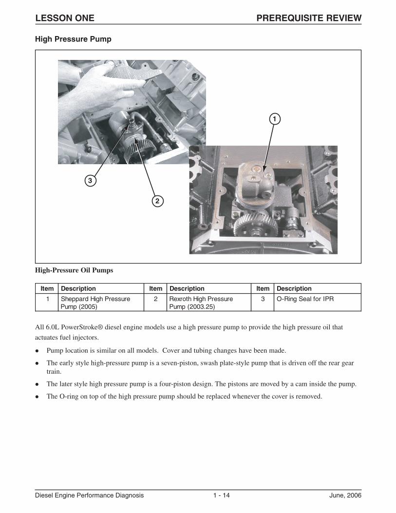
All 6.0L PowerStroke® diesel engine models use a high pressure pump to provide the high pressure oil that
actuates fuel injectors.
� Pump location is similar on all models. Cover and tubing changes have been made.
� The early style high-pressure pump is a seven-piston, swash plate-style pump that is driven off the rear geartrain.
� The later style high pressure pump is a four-piston design. The pistons are moved by a cam inside the pump.
� The O-ring on top of the high pressure pump should be replaced whenever the cover is removed.
High Pressure Pump
High-Pressure Oil Pumps
1
3
2
metI noitpircseD metI noitpircseD metI noitpircseD
1 erusserPhgiHdrappehS)5002(pmuP
2 erusserPhgiHhtorxeR)52.3002(pmuP
3 RPIroflaeSgniR-O
LESSON ONE PREREQUISITE REVIEW
Diesel Engine Performance Diagnosis 1 - 15 June, 2006
Injector Pressure Regulator (IPR) Valve
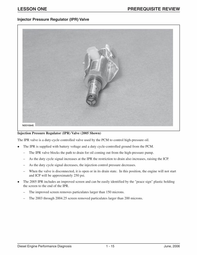
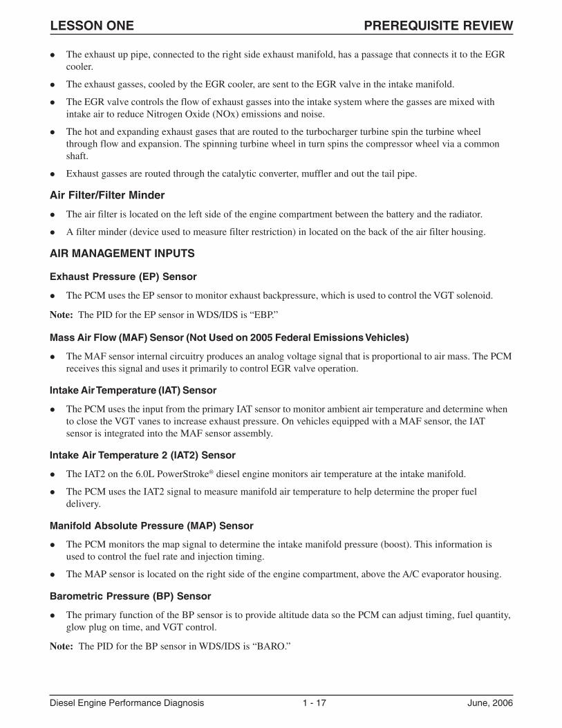
Injection Pressure Regulator (IPR) Valve (2005 Shown)
The IPR valve is a duty-cycle controlled valve used by the PCM to control high-pressure oil.
� The IPR is supplied with battery voltage and a duty cycle-controlled ground from the PCM.
– The IPR valve blocks the path to drain for oil coming out from the high-pressure pump.
– As the duty cycle signal increases at the IPR the restriction to drain also increases, raising the ICP.
– As the duty cycle signal decreases, the injection control pressure decreases.
– When the valve is disconnected, it is open or in its drain state. In this position, the engine will not startand ICP will be approximately 250 psi.
� The 2005 IPR includes an improved screen and can be easily identified by the "peace sign" plastic holdingthe screen to the end of the IPR.
– The improved screen removes particulates larger than 150 microns.
– The 2003 through 2004.25 screen removed particulates larger than 200 microns.
LESSON ONE PREREQUISITE REVIEW
Diesel Engine Performance Diagnosis 1 - 16 June, 2006
AIR MANAGEMENT SYSTEM
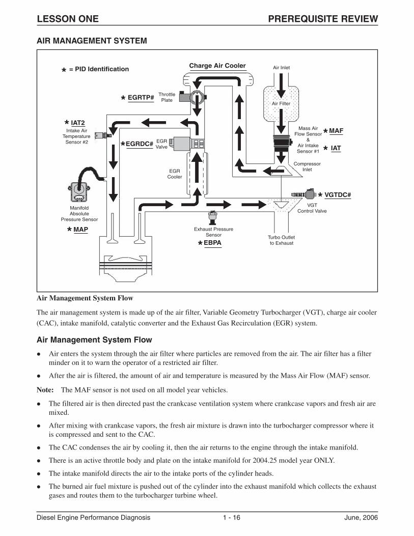
Air Management System Flow
The air management system is made up of the air filter, Variable Geometry Turbocharger (VGT), charge air cooler
(CAC), intake manifold, catalytic converter and the Exhaust Gas Recirculation (EGR) system.
Air Management System Flow
� Air enters the system through the air filter where particles are removed from the air. The air filter has a filterminder on it to warn the operator of a restricted air filter.
� After the air is filtered, the amount of air and temperature is measured by the Mass Air Flow (MAF) sensor.
Note: The MAF sensor is not used on all model year vehicles.
� The filtered air is then directed past the crankcase ventilation system where crankcase vapors and fresh air aremixed.
� After mixing with crankcase vapors, the fresh air mixture is drawn into the turbocharger compressor where itis compressed and sent to the CAC.
� The CAC condenses the air by cooling it, then the air returns to the engine through the intake manifold.
� There is an active throttle body and plate on the intake manifold for 2004.25 model year ONLY.
� The intake manifold directs the air to the intake ports of the cylinder heads.
� The burned air fuel mixture is pushed out of the cylinder into the exhaust manifold which collects the exhaustgases and routes them to the turbocharger turbine wheel.
Charge Air Cooler= PID Identification
EGRTP#
EGRDC#
IAT2
MAP
EBPA
VGTDC#
IAT
MAF
ThrottlePlate
EGRValve
EGRCooler
ManifoldAbsolute
Pressure Sensor
Intake AirTemperature
Sensor #2
Air Inlet
Air Filter
Mass AirFlow Sensor
&Air IntakeSensor #1
CompressorInlet
VGTControl Valve
Exhaust PressureSensor
*
*
*
*
*
*
**
*Turbo Outletto Exhaust
LESSON ONE PREREQUISITE REVIEW
Diesel Engine Performance Diagnosis 1 - 17 June, 2006
� The exhaust up pipe, connected to the right side exhaust manifold, has a passage that connects it to the EGRcooler.
� The exhaust gasses, cooled by the EGR cooler, are sent to the EGR valve in the intake manifold.
� The EGR valve controls the flow of exhaust gasses into the intake system where the gasses are mixed withintake air to reduce Nitrogen Oxide (NOx) emissions and noise.
� The hot and expanding exhaust gases that are routed to the turbocharger turbine spin the turbine wheelthrough flow and expansion. The spinning turbine wheel in turn spins the compressor wheel via a commonshaft.
� Exhaust gasses are routed through the catalytic converter, muffler and out the tail pipe.
Air Filter/Filter Minder
� The air filter is located on the left side of the engine compartment between the battery and the radiator.
� A filter minder (device used to measure filter restriction) in located on the back of the air filter housing.
AIR MANAGEMENT INPUTS
Exhaust Pressure (EP) Sensor
� The PCM uses the EP sensor to monitor exhaust backpressure, which is used to control the VGT solenoid.
Note: The PID for the EP sensor in WDS/IDS is “EBP.”
Mass Air Flow (MAF) Sensor (Not Used on 2005 Federal Emissions Vehicles)
� The MAF sensor internal circuitry produces an analog voltage signal that is proportional to air mass. The PCMreceives this signal and uses it primarily to control EGR valve operation.
Intake Air Temperature (IAT) Sensor
� The PCM uses the input from the primary IAT sensor to monitor ambient air temperature and determine whento close the VGT vanes to increase exhaust pressure. On vehicles equipped with a MAF sensor, the IATsensor is integrated into the MAF sensor assembly.
Intake Air Temperature 2 (IAT2) Sensor
� The IAT2 on the 6.0L PowerStroke® diesel engine monitors air temperature at the intake manifold.
� The PCM uses the IAT2 signal to measure manifold air temperature to help determine the proper fueldelivery.
Manifold Absolute Pressure (MAP) Sensor
� The PCM monitors the map signal to determine the intake manifold pressure (boost). This information isused to control the fuel rate and injection timing.
� The MAP sensor is located on the right side of the engine compartment, above the A/C evaporator housing.
Barometric Pressure (BP) Sensor
� The primary function of the BP sensor is to provide altitude data so the PCM can adjust timing, fuel quantity,glow plug on time, and VGT control.
Note: The PID for the BP sensor in WDS/IDS is “BARO.”
LESSON ONE PREREQUISITE REVIEW
Diesel Engine Performance Diagnosis 1 - 18 June, 2006
AIR MANAGEMENT OUTPUTS
Turbocharger System
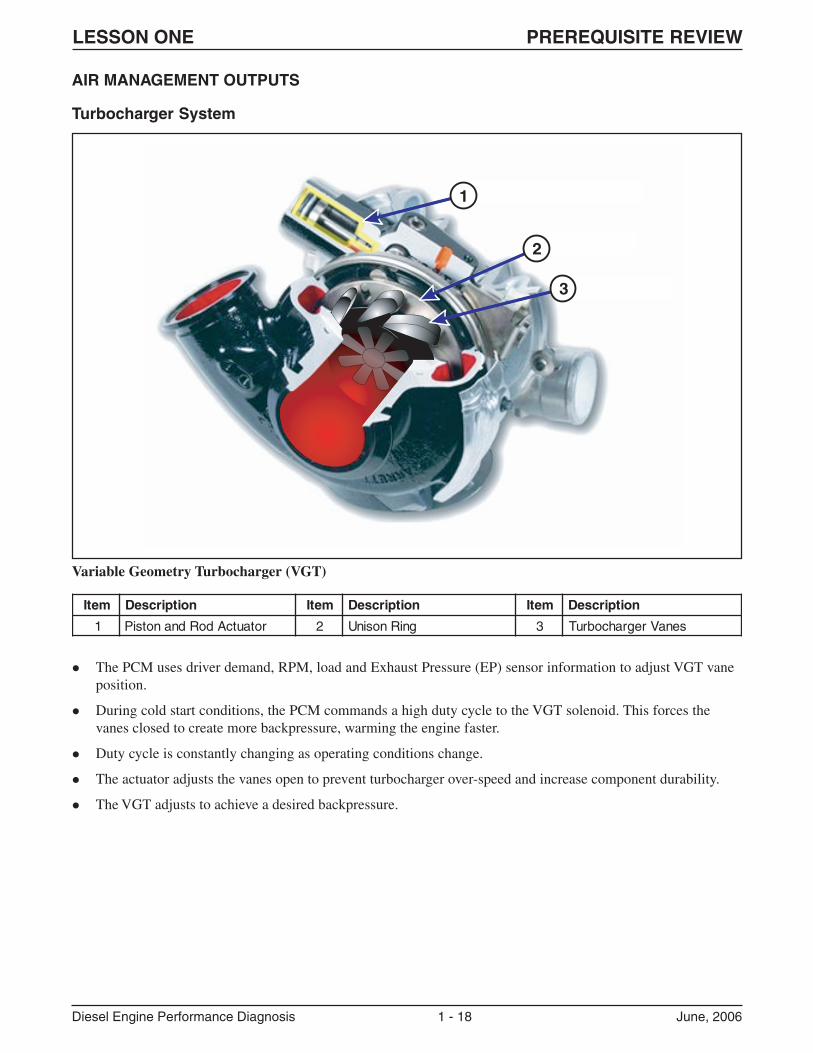
Variable Geometry Turbocharger (VGT)
� The PCM uses driver demand, RPM, load and Exhaust Pressure (EP) sensor information to adjust VGT vaneposition.
� During cold start conditions, the PCM commands a high duty cycle to the VGT solenoid. This forces thevanes closed to create more backpressure, warming the engine faster.
� Duty cycle is constantly changing as operating conditions change.
� The actuator adjusts the vanes open to prevent turbocharger over-speed and increase component durability.
� The VGT adjusts to achieve a desired backpressure.
1
2
3
metI noitpircseD metI noitpircseD metI noitpircseD
1 rotautcAdoRdnanotsiP 2 gniRnosinU 3 senaVregrahcobruT
LESSON ONE PREREQUISITE REVIEW
Diesel Engine Performance Diagnosis 1 - 19 June, 2006
Exhaust Gas Recirculation (EGR) System
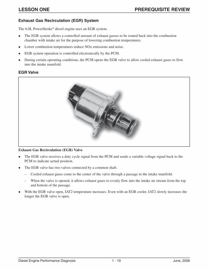
Exhaust Gas Recirculation (EGR) Valve
� The EGR valve receives a duty cycle signal from the PCM and sends a variable voltage signal back to thePCM to indicate actual position.
� The EGR valve has two valves connected by a common shaft.
– Cooled exhaust gases come to the center of the valve through a passage in the intake manifold.
– When the valve is opened, it allows exhaust gases to evenly flow into the intake air stream from the topand bottom of the passage.
� With the EGR valve open, IAT2 temperature increases. Even with an EGR cooler, IAT2 slowly increases thelonger the EGR valve is open.
The 6.0L PowerStroke® diesel engine uses an EGR system.
� The EGR system allows a controlled amount of exhaust gasses to be routed back into the combustionchamber with intake air for the purpose of lowering combustion temperatures.
� Lower combustion temperatures reduce NOx emissions and noise.
� EGR system operation is controlled electronically by the PCM.
� During certain operating conditions, the PCM opens the EGR valve to allow cooled exhaust gases to flowinto the intake manifold.
EGR Valve
LESSON ONE PREREQUISITE REVIEW
Diesel Engine Performance Diagnosis 1 - 20 June, 2006
EGR Throttle Plate
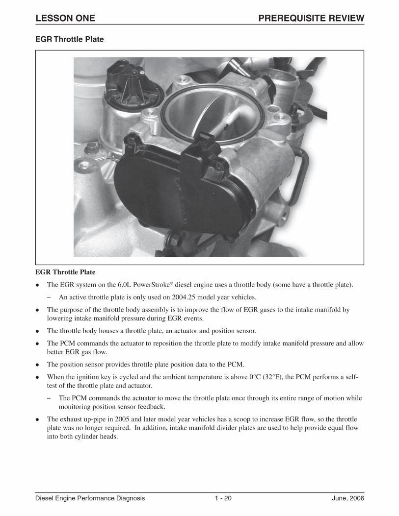
EGR Throttle Plate
� The EGR system on the 6.0L PowerStroke® diesel engine uses a throttle body (some have a throttle plate).
– An active throttle plate is only used on 2004.25 model year vehicles.
� The purpose of the throttle body assembly is to improve the flow of EGR gases to the intake manifold bylowering intake manifold pressure during EGR events.
� The throttle body houses a throttle plate, an actuator and position sensor.
� The PCM commands the actuator to reposition the throttle plate to modify intake manifold pressure and allowbetter EGR gas flow.
� The position sensor provides throttle plate position data to the PCM.
� When the ignition key is cycled and the ambient temperature is above 0°C (32°F), the PCM performs a self-test of the throttle plate and actuator.
– The PCM commands the actuator to move the throttle plate once through its entire range of motion whilemonitoring position sensor feedback.
� The exhaust up-pipe in 2005 and later model year vehicles has a scoop to increase EGR flow, so the throttleplate was no longer required. In addition, intake manifold divider plates are used to help provide equal flowinto both cylinder heads.
LESSON ONE PREREQUISITE REVIEW
Diesel Engine Performance Diagnosis 1 - 21 June, 2006
EGR Cooler
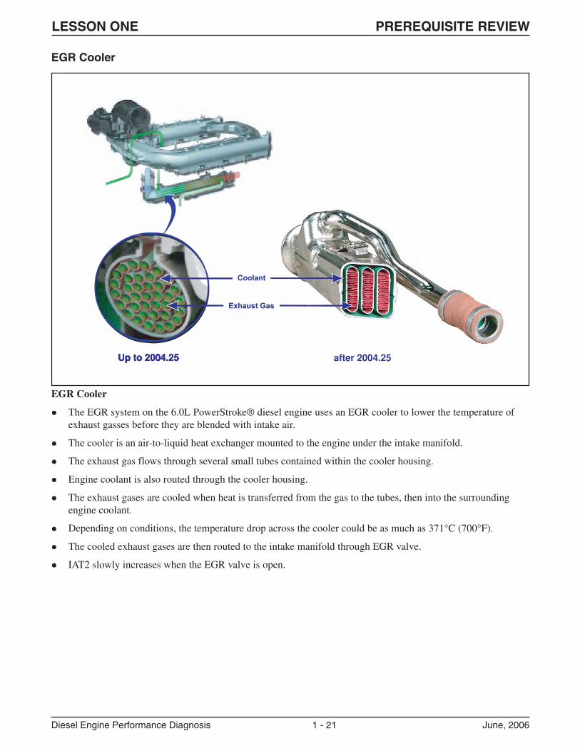
EGR Cooler
� The EGR system on the 6.0L PowerStroke® diesel engine uses an EGR cooler to lower the temperature ofexhaust gasses before they are blended with intake air.
� The cooler is an air-to-liquid heat exchanger mounted to the engine under the intake manifold.
� The exhaust gas flows through several small tubes contained within the cooler housing.
� Engine coolant is also routed through the cooler housing.
� The exhaust gases are cooled when heat is transferred from the gas to the tubes, then into the surroundingengine coolant.
� Depending on conditions, the temperature drop across the cooler could be as much as 371°C (700°F).
� The cooled exhaust gases are then routed to the intake manifold through EGR valve.
� IAT2 slowly increases when the EGR valve is open.
LESSON ONE PREREQUISITE REVIEW
Diesel Engine Performance Diagnosis 1 - 22 June, 2006
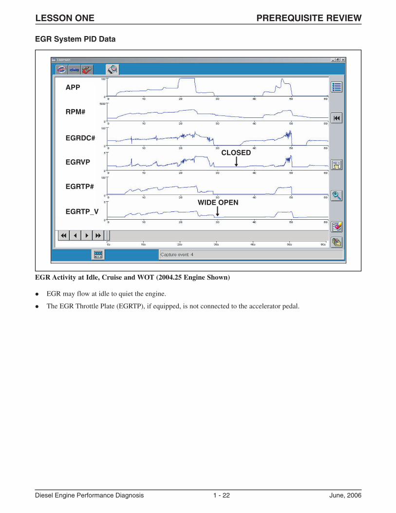
EGR Activity at Idle, Cruise and WOT (2004.25 Engine Shown)
� EGR may flow at idle to quiet the engine.
� The EGR Throttle Plate (EGRTP), if equipped, is not connected to the accelerator pedal.
EGR System PID Data
APP
CLOSED
WIDE OPEN
RPM#
EGRDC#
EGRVP
EGRTP#
EGRTP_V
LESSON ONE WORKSTATIONS
Diesel Engine Performance Diagnosis 1 - 23 June, 2006
LESSON ONEWORKSTATIONS
Workstation: Summary:
1 Service Publications navigation activity, in which students will navigate various Service
Publications to answer the questions in the worksheet.
2 Hands-on activity at vehicle that requires students to use WDS to select PIDs, record
and save a PID data session, and review the session to answer the questions in the
worksheet. Students are not looking for a “bug” in this activity.
3 “Paper and pencil” activity in which students will analyze PID data in several WDS
screenprints, and relate the readings in these prints to normal operation on the 6.0L
PowerStroke® diesel engine.
4 Hands-on activity at the 6.0L PowerStroke® diesel engine on the stand. In this activity,
students will disassemble and assemble the components necessary to access the high pressure
oil pump.
LESSON ONE WORKSTATION 1
Diesel Engine Performance Diagnosis 1 - 24 June, 2006
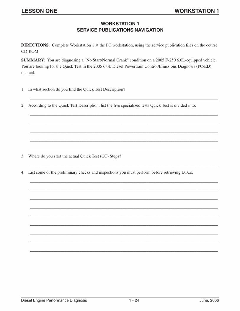
WORKSTATION 1SERVICE PUBLICATIONS NAVIGATION
DIRECTIONS: Complete Workstation 1 at the PC workstation, using the service publication files on the course
CD-ROM.
SUMMARY: You are diagnosing a "No Start/Normal Crank" condition on a 2005 F-250 6.0L-equipped vehicle.
You are looking for the Quick Test in the 2005 6.0L Diesel Powertrain Control/Emissions Diagnosis (PC/ED)
manual.
1. In what section do you find the Quick Test Description?
_______________________________________________________________________________________
2. According to the Quick Test Description, list the five specialized tests Quick Test is divided into:
_______________________________________________________________________________________
_______________________________________________________________________________________
_______________________________________________________________________________________
_______________________________________________________________________________________
_______________________________________________________________________________________
3. Where do you start the actual Quick Test (QT) Steps?
_______________________________________________________________________________________
4. List some of the preliminary checks and inspections you must perform before retrieving DTCs.
_______________________________________________________________________________________
_______________________________________________________________________________________
_______________________________________________________________________________________
_______________________________________________________________________________________
_______________________________________________________________________________________
_______________________________________________________________________________________
_______________________________________________________________________________________
_______________________________________________________________________________________
_______________________________________________________________________________________
LESSON ONE WORKSTATION 1
Diesel Engine Performance Diagnosis 1 - 25 June, 2006
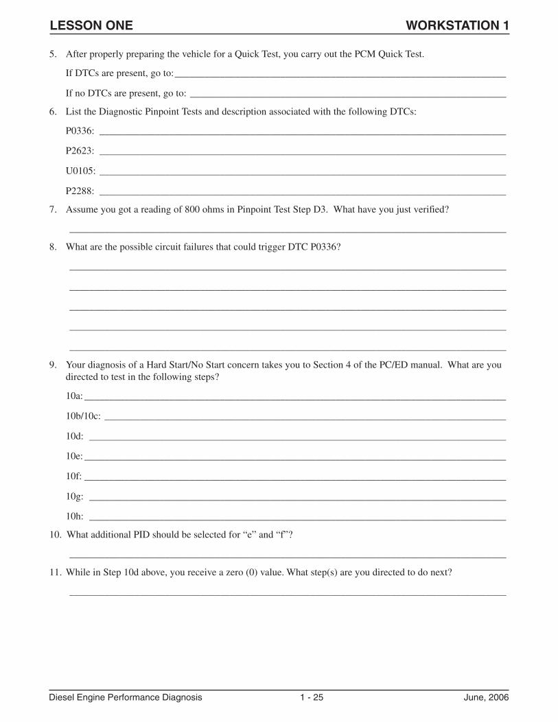
5. After properly preparing the vehicle for a Quick Test, you carry out the PCM Quick Test.
If DTCs are present, go to:__________________________________________________________________
If no DTCs are present, go to: _______________________________________________________________
6. List the Diagnostic Pinpoint Tests and description associated with the following DTCs:
P0336: _________________________________________________________________________________
P2623: _________________________________________________________________________________
U0105: _________________________________________________________________________________
P2288: _________________________________________________________________________________
7. Assume you got a reading of 800 ohms in Pinpoint Test Step D3. What have you just verified?
_______________________________________________________________________________________
8. What are the possible circuit failures that could trigger DTC P0336?
_______________________________________________________________________________________
_______________________________________________________________________________________
_______________________________________________________________________________________
_______________________________________________________________________________________
_______________________________________________________________________________________
9. Your diagnosis of a Hard Start/No Start concern takes you to Section 4 of the PC/ED manual. What are youdirected to test in the following steps?
10a: ____________________________________________________________________________________
10b/10c: ________________________________________________________________________________
10d: ___________________________________________________________________________________
10e: ____________________________________________________________________________________
10f: ____________________________________________________________________________________
10g: ___________________________________________________________________________________
10h: ___________________________________________________________________________________
10. What additional PID should be selected for “e” and “f”?
_______________________________________________________________________________________
11. While in Step 10d above, you receive a zero (0) value. What step(s) are you directed to do next?
_______________________________________________________________________________________
LESSON ONE WORKSTATION 1
Diesel Engine Performance Diagnosis 1 - 26 June, 2006
12. In what service publication would you find the Turbocharger Performance Test?
_______________________________________________________________________________________
13. Where would you find Turbocharger Component Tests, such as the bearing clearance check?
_______________________________________________________________________________________
What other turbocharger tests are available in this location?
_______________________________________________________________________________________
_______________________________________________________________________________________
_______________________________________________________________________________________
_______________________________________________________________________________________
14. Locate the Electronic Engine Controls diagram in the 2005 F-Super Duty Wiring Diagrams manual. On whatcell does this diagram start?
_______________________________________________________________________________________
15. What connector identification is used for the MAF sensor?
_______________________________________________________________________________________
16. What components would be affected if the wire for CKT 570 was open between S106 and G101?
_______________________________________________________________________________________
Note: Close all service publications before leaving this workstation.
LESSON ONE WORKSTATION 2
Diesel Engine Performance Diagnosis 1 - 27 June, 2006
WORKSTATION 2ON-VEHICLE PID SELECTION, RECORDING AND ANALYSIS USING WDS/IDS
DIRECTIONS: Complete Workstation 2 at the VEHICLE workstation, following the steps on this worksheet.
SUMMARY: This activity allows you to select and view various 6.0L PowerStroke® diesel performance
parameters under “normal” conditions. You are not diagnosing a customer concern in this activity.
Perform the following steps:
1. Perform all preliminary set up tasks for vehicle safety. (Block wheels, transmission in Park, set park brake.)
� Connect the WDS.
� Establish WDS session.
� Perform KOEO Self-Test and record any DTCs. Exit Self-Test when finished.
� Select Datalogger function. Select “Powertrain,” then select “Engine.”
� Press Erasure button.
� Select the PIDs listed on the next page and press “Save Parameter and Display Settings.”
� View PID list and fill in KOEO values on the next page.
� Push Record button and start engine. This will give 15 seconds before the start event and 15 seconds after thestart event of recording time.
� View PID list and fill in KOER values on the next page.
� Shut off engine.
� Name the file (Your name).
� Name description (i.e.: Normal_1, LowPower_2)
� Review recording and compare to written list.
LESSON ONE WORKSTATION 2
Diesel Engine Performance Diagnosis 1 - 28 June, 2006
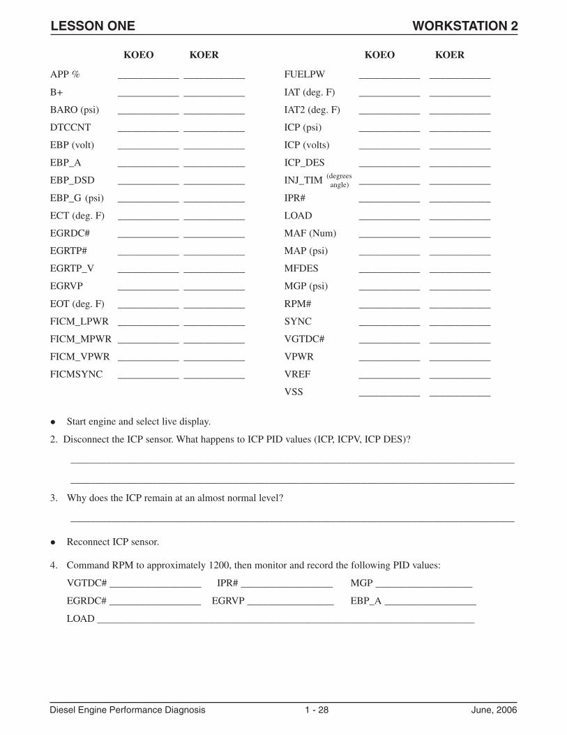
KOEO KOER KOEO KOER
APP % ____________ ____________ FUELPW ____________ ____________
B+ ____________ ____________ IAT (deg. F) ____________ ____________
BARO (psi) ____________ ____________ IAT2 (deg. F) ____________ ____________
DTCCNT ____________ ____________ ICP (psi) ____________ ____________
EBP (volt) ____________ ____________ ICP (volts) ____________ ____________
EBP_A ____________ ____________ ICP_DES ____________ ____________
EBP_DSD ____________ ____________ INJ_TIM ____________ ____________
EBP_G (psi) ____________ ____________ IPR# ____________ ____________
ECT (deg. F) ____________ ____________ LOAD ____________ ____________
EGRDC# ____________ ____________ MAF (Num) ____________ ____________
EGRTP# ____________ ____________ MAP (psi) ____________ ____________
EGRTP_V ____________ ____________ MFDES ____________ ____________
EGRVP ____________ ____________ MGP (psi) ____________ ____________
EOT (deg. F) ____________ ____________ RPM# ____________ ____________
FICM_LPWR ____________ ____________ SYNC ____________ ____________
FICM_MPWR ____________ ____________ VGTDC# ____________ ____________
FICM_VPWR ____________ ____________ VPWR ____________ ____________
FICMSYNC ____________ ____________ VREF ____________ ____________
VSS ____________ ____________
� Start engine and select live display.
2. Disconnect the ICP sensor. What happens to ICP PID values (ICP, ICPV, ICP DES)?
_______________________________________________________________________________________
_______________________________________________________________________________________
3. Why does the ICP remain at an almost normal level?
_______________________________________________________________________________________
� Reconnect ICP sensor.
4. Command RPM to approximately 1200, then monitor and record the following PID values:
VGTDC# __________________ IPR# __________________ MGP ___________________
EGRDC# __________________ EGRVP _________________ EBP_A __________________
LOAD __________________________________________________________________________
(degrees angle)
LESSON ONE WORKSTATION 2
Diesel Engine Performance Diagnosis 1 - 29 June, 2006
5. Command VGT duty cycle to 0% and then up to 85%. What happens to the EBP_A PID?
@ 0% __________________________________________________________________________________
@ 85% _________________________________________________________________________________
6. Command EGR open, then closed with VGT at 85%. What happens to the EBP_A PID?
@ open ________________________________________________________________________________
@ closed _______________________________________________________________________________
� Release control of engine RPM.
7. Why do the two events in Questions 5 and 6 occur?
_______________________________________________________________________________________
_______________________________________________________________________________________
� Go to PID screen, select “Load Parameters” icon and highlight your file(s).
� Select “Delete File” icon, confirm and exit Datalogger.
� Perform a Power Balance Test, then exit.
� Perform a Relative Compression Test, then exit.
8. What would cause a good Relative Compression reading, but have one weak cylinder on the Power BalanceTest?
_______________________________________________________________________________________
_______________________________________________________________________________________
� Clear DTCs and delete session.
LESSON ONE WORKSTATION 3
Diesel Engine Performance Diagnosis 1 - 30 June, 2006
WORKSTATION 3WDS PID DATA ANALYSIS – 6.0L DIESEL SENSOR VALUE COMPARISON
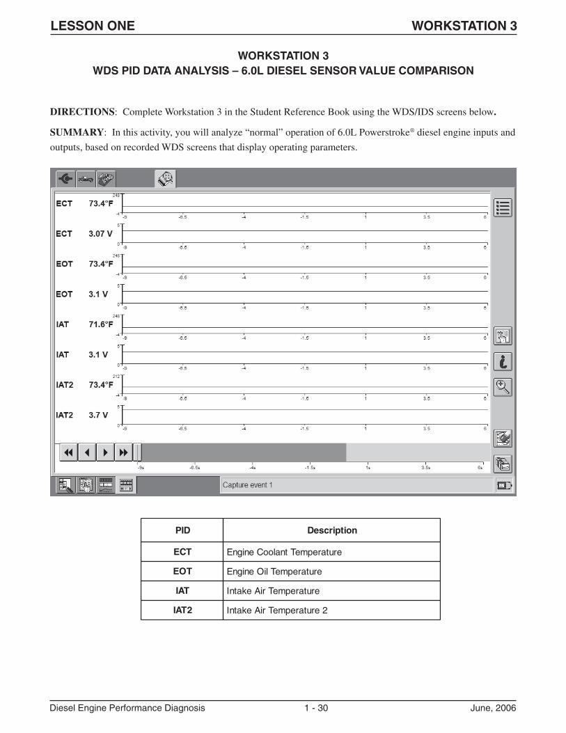
DIRECTIONS: Complete Workstation 3 in the Student Reference Book using the WDS/IDS screens below.
SUMMARY: In this activity, you will analyze “normal” operation of 6.0L Powerstroke® diesel engine inputs and
outputs, based on recorded WDS screens that display operating parameters.
DIP noitpircseD
TCE erutarepmeTtnalooCenignE
TOE erutarepmeTliOenignE
TAI erutarepmeTriAekatnI
2TAI 2erutarepmeTriAekatnI
LESSON ONE WORKSTATION 3
Diesel Engine Performance Diagnosis 1 - 31 June, 2006
1. What can you determine about vehicle condition by the previous readings?
_______________________________________________________________________________________
_______________________________________________________________________________________
2. Do all the temperature sensor volt or temp PIDs match?
volts ___________________________________________________________________________________
temps __________________________________________________________________________________
3. If you viewed the same four sensors under the same conditions, but one sensor's data was significantlydifferent from the above readings, what could you assume?
_______________________________________________________________________________________
_______________________________________________________________________________________
_______________________________________________________________________________________
� For the next question, assume you commanded the EGR valve open at an idle. When this is done, the IAT2reading increases because hot exhaust gases are being directed into the intake manifold.
4. How can the above information be used for EGR diagnosis?
_______________________________________________________________________________________
_______________________________________________________________________________________
_______________________________________________________________________________________
LESSON ONE WORKSTATION 3
Diesel Engine Performance Diagnosis 1 - 32 June, 2006
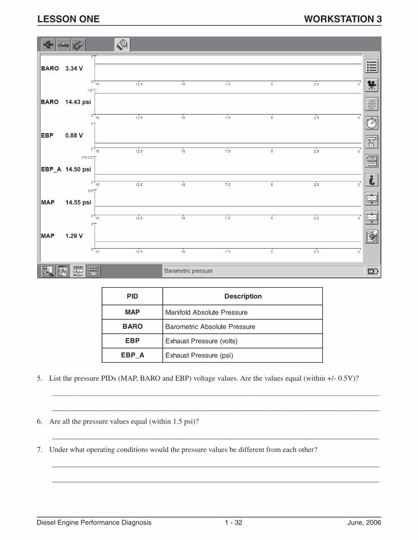
5. List the pressure PIDs (MAP, BARO and EBP) voltage values. Are the values equal (within +/- 0.5V)?
_______________________________________________________________________________________
_______________________________________________________________________________________
6. Are all the pressure values equal (within 1.5 psi)?
_______________________________________________________________________________________
7. Under what operating conditions would the pressure values be different from each other?
_______________________________________________________________________________________
_______________________________________________________________________________________
DIP noitpircseD
PAM erusserPetulosbAdlofinaM
ORAB erusserPetulosbAcirtemoraB
PBE )stlov(erusserPtsuahxE
A_PBE )isp(erusserPtsuahxE
LESSON ONE WORKSTATION 3
Diesel Engine Performance Diagnosis 1 - 33 June, 2006
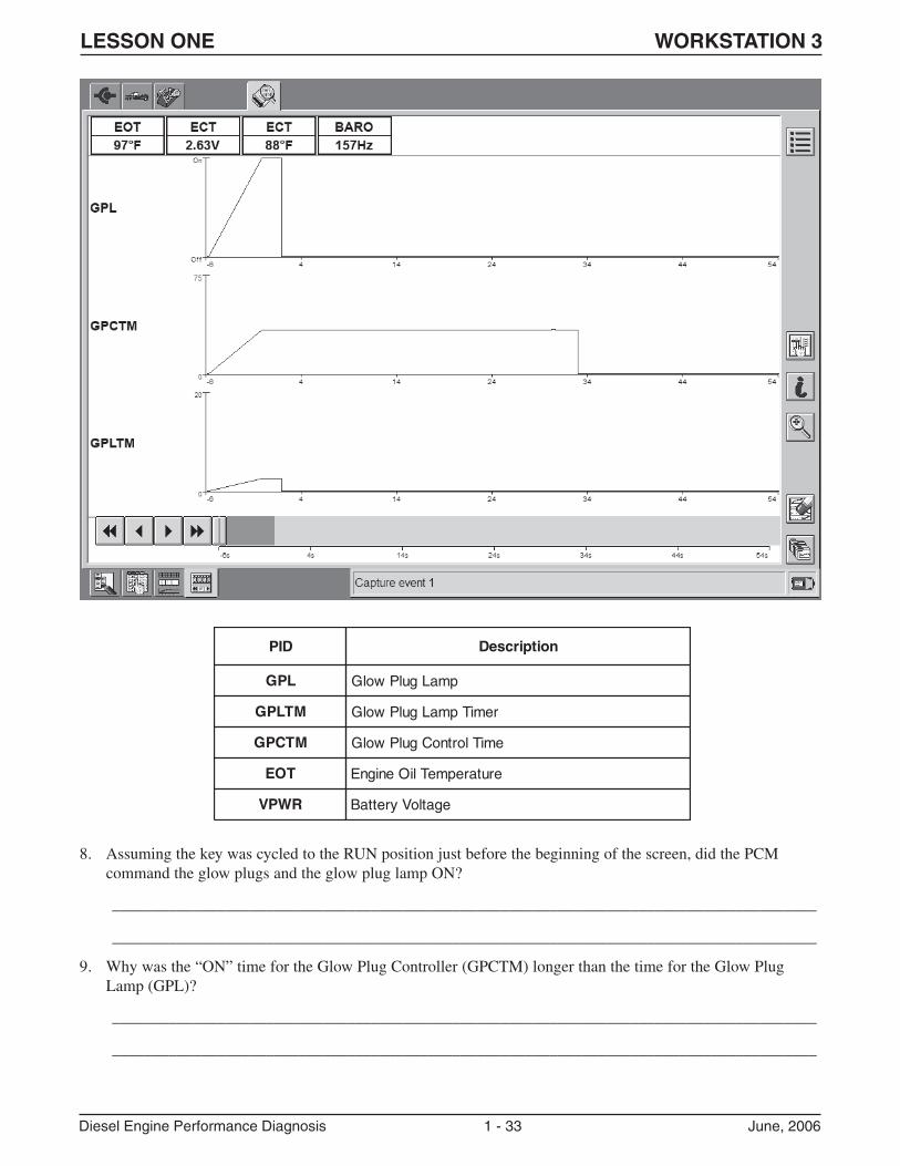
8. Assuming the key was cycled to the RUN position just before the beginning of the screen, did the PCMcommand the glow plugs and the glow plug lamp ON?
_______________________________________________________________________________________
_______________________________________________________________________________________
9. Why was the “ON” time for the Glow Plug Controller (GPCTM) longer than the time for the Glow PlugLamp (GPL)?
_______________________________________________________________________________________
_______________________________________________________________________________________
DIP noitpircseD
LPG pmaLgulPwolG
MTLPG remiTpmaLgulPwolG
MTCPG emiTlortnoCgulPwolG
TOE erutarepmeTliOenignE
RWPV egatloVyrettaB
LESSON ONE WORKSTATION 3
Diesel Engine Performance Diagnosis 1 - 34 June, 2006
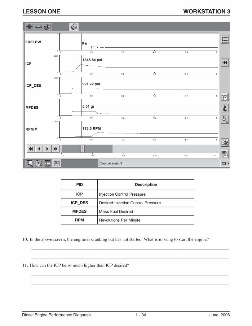
10. In the above screen, the engine is cranking but has not started. What is missing to start the engine?
_______________________________________________________________________________________
_______________________________________________________________________________________
11. How can the ICP be so much higher than ICP desired?
_______________________________________________________________________________________
_______________________________________________________________________________________
DIP noitpircseD
PCI erusserPlortnoCnoitcejnI
SED_PCI erusserPlortnoCnoitcejnIderiseD
SEDFM deriseDleuFssaM
MPR etuniMrePsnoituloveR
LESSON ONE WORKSTATION 3
Diesel Engine Performance Diagnosis 1 - 35 June, 2006
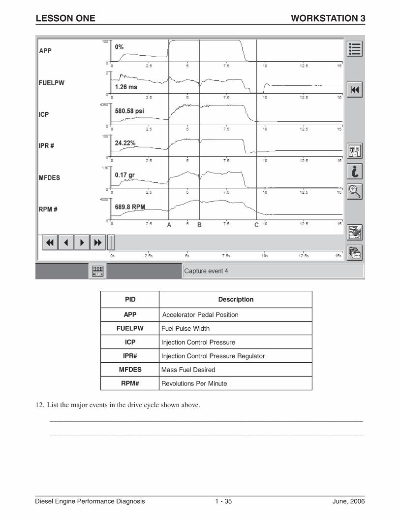
12. List the major events in the drive cycle shown above.
_______________________________________________________________________________________
_______________________________________________________________________________________
DIP noitpircseD
PPA noitisoPladeProtareleccA
WPLEUF htdiWesluPleuF
PCI erusserPlortnoCnoitcejnI
#RPI rotalugeRerusserPlortnoCnoitcejnI
SEDFM deriseDleuFssaM
#MPR etuniMrePsnoituloveR
LESSON ONE WORKSTATION 3
Diesel Engine Performance Diagnosis 1 - 36 June, 2006
13. Why did the FUELPW increase at point A?
_______________________________________________________________________________________
_______________________________________________________________________________________
_______________________________________________________________________________________
14. Why did FUELPW decrease at point B?
_______________________________________________________________________________________
_______________________________________________________________________________________
_______________________________________________________________________________________
15. Why did the MFDES and FUELPW drop to 0 at point C?
_______________________________________________________________________________________
_______________________________________________________________________________________
_______________________________________________________________________________________
LESSON ONE WORKSTATION 4
Diesel Engine Performance Diagnosis 1 - 37 June, 2006
WORKSTATION 4HIGH PRESSURE OIL PUMP SERVICE ON 6.0L ENGINE
DIRECTIONS: Complete Workstation 4 at the ENGINE workstation, using the tools and service information
available at the workstation.
SUMMARY: In this activity, you will disassemble the upper part of the engine as far as necessary to remove the
high pressure oil pump, following the steps below. Answer the questions as you proceed.
1. Remove right valve cover, high pressure manifold fasteners and high pressure manifold from the right side ofthe engine. What is the torque specification for the T-30 Torx fastener?
_______________________________________________________________________________________
2. When performing in-vehicle service, why would you NOT remove the high pressure stand pipe with the highpressure manifold?
_______________________________________________________________________________________
3. Which plug in the high-pressure manifold has the tube under it?
_______________________________________________________________________________________
� Continue disassembly until the turbocharger and drain tube are removed.
4. Are the VGT oil drain tube O-rings reusable?
_______________________________________________________________________________________
5. What could happen if the metal circular gasket for the EGR cooler inlet is not reinstalled upon coolerinstallation?
_______________________________________________________________________________________
6. Why would you loosen the oil filter cap to allow air into the housing before changing the oil?
_______________________________________________________________________________________
7. Where are the sealing washers located on the fuel line banjo fitting?
_______________________________________________________________________________________
_______________________________________________________________________________________
8. Can the sealing washers be reused?
_______________________________________________________________________________________
� Remove the IPR and high-pressure pump.
9. What is the purpose of the metallic foil on the IPR?
_______________________________________________________________________________________
Use the Workshop Manual procedures to reassemble the engine for the next group.

LESSON ONE WORKSTATION 4
Diesel Engine Performance Diagnosis 1 - 38 June, 2006
NOTES:
LESSON TWO WORKSTATIONS
Diesel Engine Performance Diagnosis 2 - 1 June, 2006
LESSON TWOWORKSTATIONS
Workstation: Summary:
1 PID data analysis activity in which students will view and analyze a WDS recording
from a 2003 6.0L-equipped Excursion to determine the cause of a “lack of power”
concern.
2 Hands-on activity at vehicle that requires students to use WDS, Service Publications and
other necessary tools to diagnose a “No Start” concern on the vehicle.
3 CMT activity in which students will diagnose the cause of an intermittent “lack of
power” concern in the “virtual shop” and fill in any necessary answers on the
worksheet.
4 Hands-on activity at the 6.0L PowerStroke® diesel engine on the stand. In this activity,
students will: (1) locate potential leak points on the engine and identify sealing methods
used, and (2) perform rocker arm service using the necessary special tools and Service
Information.
LESSON TWO WORKSTATION 1
Diesel Engine Performance Diagnosis 2 - 2 June, 2006
WORKSTATION 1POOR PERFORMANCE / LACK OF POWER USING PID DATA ANALYSIS
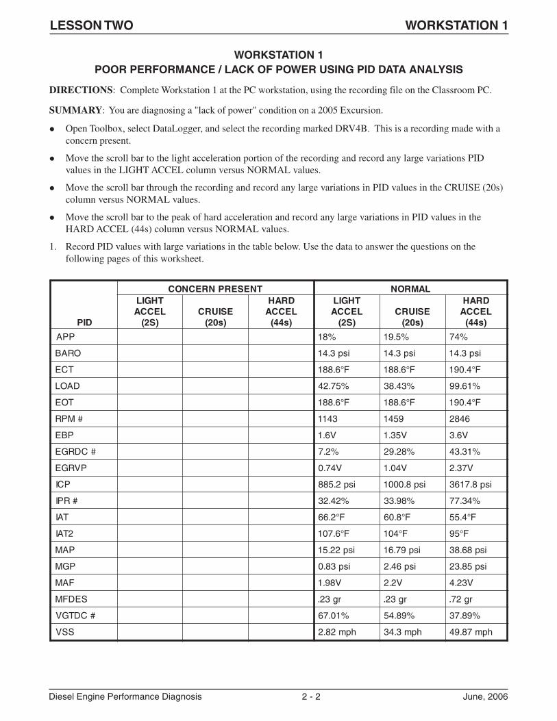
DIRECTIONS: Complete Workstation 1 at the PC workstation, using the recording file on the Classroom PC.
SUMMARY: You are diagnosing a "lack of power" condition on a 2005 Excursion.
� Open Toolbox, select DataLogger, and select the recording marked DRV4B. This is a recording made with aconcern present.
� Move the scroll bar to the light acceleration portion of the recording and record any large variations PIDvalues in the LIGHT ACCEL column versus NORMAL values.
� Move the scroll bar through the recording and record any large variations in PID values in the CRUISE (20s)column versus NORMAL values.
� Move the scroll bar to the peak of hard acceleration and record any large variations in PID values in theHARD ACCEL (44s) column versus NORMAL values.
1. Record PID values with large variations in the table below. Use the data to answer the questions on thefollowing pages of this worksheet.
DIP
TNESERPNRECNOC LAMRONTHGILLECCA
)S2(ESIURC
)s02(
DRAHLECCA
)s44(
THGILLECCA
)S2(ESIURC
)s02(
DRAHLECCA
)s44(
PPA %81 %5.91 %47
ORAB isp3.41 isp3.41 isp3.41
TCE F°6.881 F°6.881 F°4.091
DAOL %57.24 %34.83 %16.99
TOE F°6.881 F°6.881 F°4.091
#MPR 3411 9541 6482
PBE V6.1 V53.1 V6.3
#CDRGE %2.7 %82.92 %13.34
PVRGE V47.0 V40.1 V73.2
PCI isp2.588 isp8.0001 isp8.7163
#RPI %24.23 %89.33 %43.77
TAI F°2.66 F°8.06 F°4.55
2TAI F°6.701 F°401 F°59
PAM isp22.51 isp97.61 isp86.83
PGM isp38.0 isp64.2 isp58.32
FAM V89.1 V2.2 V32.4
SEDFM rg32. rg32. rg27.
#CDTGV %10.76 %98.45 %98.73
SSV hpm28.2 hpm3.43 hpm78.94
LESSON TWO WORKSTATION 1
Diesel Engine Performance Diagnosis 2 - 3 June, 2006
2. What does the MGP PID value from CONCERN PRESENT recording tell you about the performance of theengine?
_______________________________________________________________________________________
3. Which PIDs were most affected by the concern?
_______________________________________________________________________________________
_______________________________________________________________________________________
4. Is the BARO PID value affected by the fault? Why or why not?
_______________________________________________________________________________________
_______________________________________________________________________________________
5. Is the EGRDC # PID value affected by the fault? Why or why not?
_______________________________________________________________________________________
_______________________________________________________________________________________
6. What conditions could cause the MGP PID value that you observed?
_______________________________________________________________________________________
_______________________________________________________________________________________
_______________________________________________________________________________________
7. Is the VGTDC # PID value affected by the fault? Why or why not?
_______________________________________________________________________________________
_______________________________________________________________________________________
_______________________________________________________________________________________
8. How does the VGT solenoid increase or decrease the exhaust pressure?
_______________________________________________________________________________________
_______________________________________________________________________________________
_______________________________________________________________________________________
_______________________________________________________________________________________
_______________________________________________________________________________________
9. What does the EBP PID value from CONCERN PRESENT recording tell you about the operating conditionof this EP sensor?
_______________________________________________________________________________________
10. Which sensor is used by the PCM as an input to adjust the VGT solenoid duty cycle?
_______________________________________________________________________________________
11. What component or system would you check further to locate the root cause of this concern?
_______________________________________________________________________________________
LESSON TWO WORKSTATION 2
Diesel Engine Performance Diagnosis 2 - 4 June, 2006
WORKSTATION 2NO START DIAGNOSIS ON-VEHICLE
DIRECTIONS: Complete Workstation 2 at the VEHICLE workstation. Use the tools and service information
available at this workstation to diagnose the concern.
� Start in the PC/ED manual, Section 3.
1. The Symptom Chart Index sends you to QT. What are the results of QT?
_______________________________________________________________________________________
_______________________________________________________________________________________
2. Based on the above result, where in the PC/ED manual do you continue your diagnosis?
_______________________________________________________________________________________
_______________________________________________________________________________________
3. Look up the customer concern in the table indicated above. What chart is indicated for the concern?
_______________________________________________________________________________________
_______________________________________________________________________________________
4. Continue your diagnosis using the chart indicated above.
� Perform Preliminary Checks.
� What was the engine oil level and condition?
_______________________________________________________________________________________
_______________________________________________________________________________________
5. Check for sufficient clean fuel. For this Workstation, check sample on bench. In your dealership, how do youcheck for sufficient clean fuel?
_______________________________________________________________________________________
_______________________________________________________________________________________
LESSON TWO WORKSTATION 2
Diesel Engine Performance Diagnosis 2 - 5 June, 2006
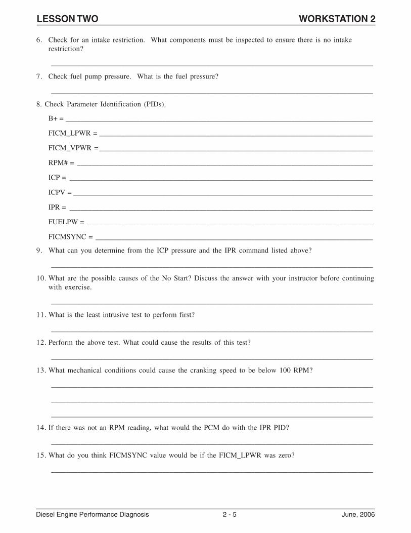
6. Check for an intake restriction. What components must be inspected to ensure there is no intakerestriction?
_______________________________________________________________________________________
7. Check fuel pump pressure. What is the fuel pressure?
_______________________________________________________________________________________
8. Check Parameter Identification (PIDs).
B+ = ___________________________________________________________________________________
FICM_LPWR = __________________________________________________________________________
FICM_VPWR = __________________________________________________________________________
RPM# = ________________________________________________________________________________
ICP = __________________________________________________________________________________
ICPV = _________________________________________________________________________________
IPR = __________________________________________________________________________________
FUELPW = _____________________________________________________________________________
FICMSYNC = ___________________________________________________________________________
9. What can you determine from the ICP pressure and the IPR command listed above?
_______________________________________________________________________________________
10. What are the possible causes of the No Start? Discuss the answer with your instructor before continuingwith exercise.
_______________________________________________________________________________________
11. What is the least intrusive test to perform first?
_______________________________________________________________________________________
12. Perform the above test. What could cause the results of this test?
_______________________________________________________________________________________
13. What mechanical conditions could cause the cranking speed to be below 100 RPM?
_______________________________________________________________________________________
_______________________________________________________________________________________
_______________________________________________________________________________________
14. If there was not an RPM reading, what would the PCM do with the IPR PID?
_______________________________________________________________________________________
15. What do you think FICMSYNC value would be if the FICM_LPWR was zero?
_______________________________________________________________________________________
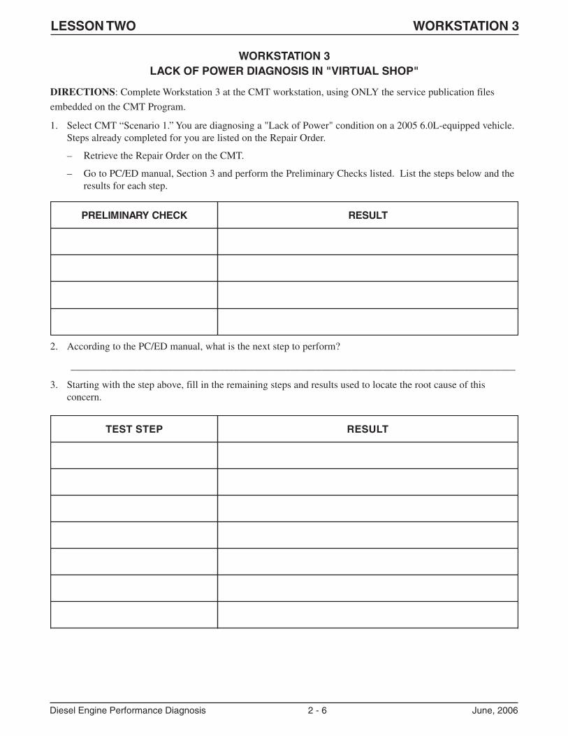
LESSON TWO WORKSTATION 3
Diesel Engine Performance Diagnosis 2 - 6 June, 2006
WORKSTATION 3LACK OF POWER DIAGNOSIS IN "VIRTUAL SHOP"
DIRECTIONS: Complete Workstation 3 at the CMT workstation, using ONLY the service publication files
embedded on the CMT Program.
1. Select CMT “Scenario 1.” You are diagnosing a "Lack of Power" condition on a 2005 6.0L-equipped vehicle.Steps already completed for you are listed on the Repair Order.
– Retrieve the Repair Order on the CMT.
– Go to PC/ED manual, Section 3 and perform the Preliminary Checks listed. List the steps below and theresults for each step.
2. According to the PC/ED manual, what is the next step to perform?
_______________________________________________________________________________________
3. Starting with the step above, fill in the remaining steps and results used to locate the root cause of thisconcern.
KCEHCYRANIMILERP TLUSER
PETSTSET TLUSER
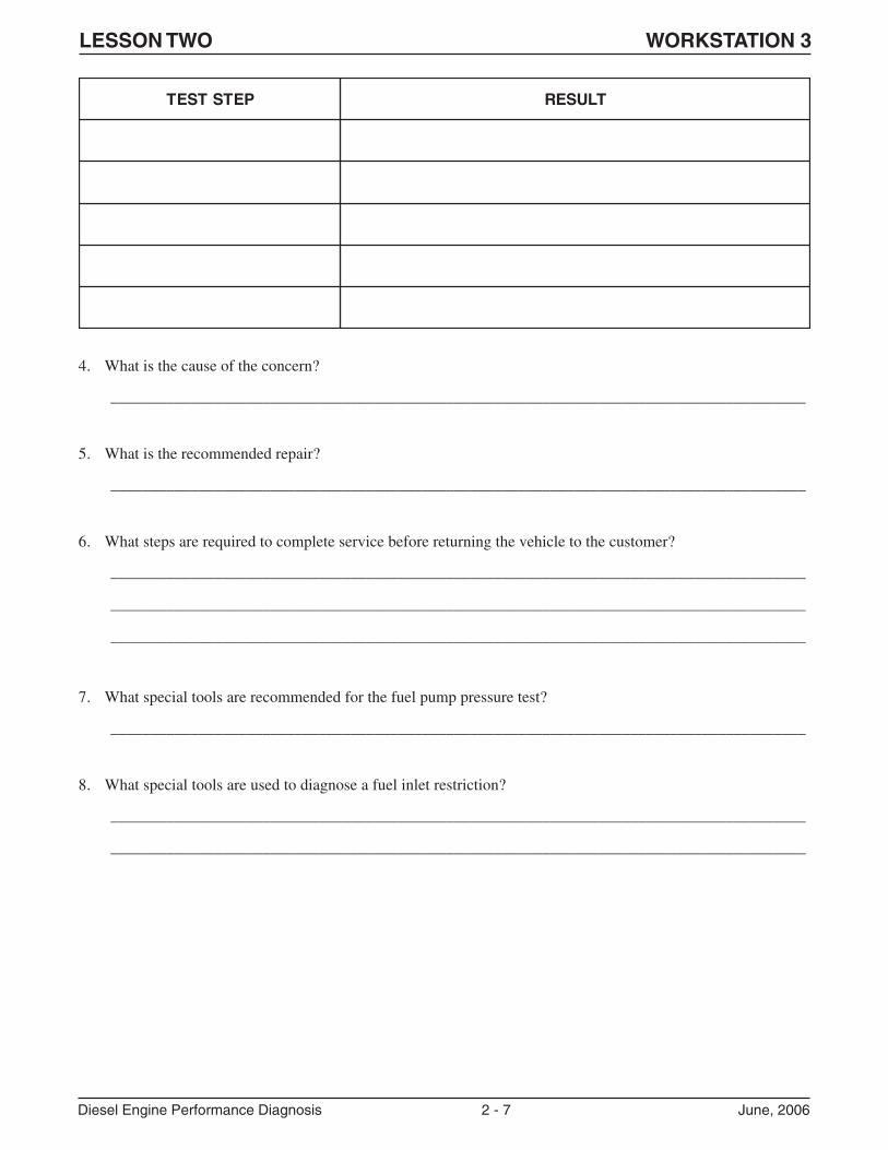
LESSON TWO WORKSTATION 3
Diesel Engine Performance Diagnosis 2 - 7 June, 2006
PETSTSET TLUSER
4. What is the cause of the concern?
_______________________________________________________________________________________
5. What is the recommended repair?
_______________________________________________________________________________________
6. What steps are required to complete service before returning the vehicle to the customer?
_______________________________________________________________________________________
_______________________________________________________________________________________
_______________________________________________________________________________________
7. What special tools are recommended for the fuel pump pressure test?
_______________________________________________________________________________________
8. What special tools are used to diagnose a fuel inlet restriction?
_______________________________________________________________________________________
_______________________________________________________________________________________
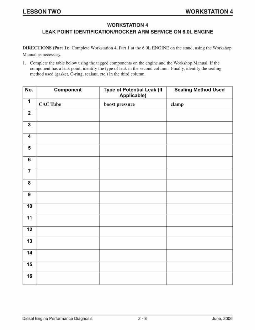
LESSON TWO WORKSTATION 4
Diesel Engine Performance Diagnosis 2 - 8 June, 2006
WORKSTATION 4LEAK POINT IDENTIFICATION/ROCKER ARM SERVICE ON 6.0L ENGINE
DIRECTIONS (Part 1): Complete Workstation 4, Part 1 at the 6.0L ENGINE on the stand, using the Workshop
Manual as necessary.
1. Complete the table below using the tagged components on the engine and the Workshop Manual. If thecomponent has a leak point, identify the type of leak in the second column. Finally, identify the sealingmethod used (gasket, O-ring, sealant, etc.) in the third column.
No. Component Type of Potential Leak (If Applicable)
Sealing Method Used
1
2
3
4
5
6
7
8
9
10
11
12
13
14
15
16
CAC Tube boost pressure clamp
LESSON TWO WORKSTATION 4
Diesel Engine Performance Diagnosis 2 - 9 June, 2006
DIRECTIONS (Part 2): Complete Workstation 4, Part 2 at the ENGINE workstation, using the tools and service
information available at the workstation. Disassemble the engine components as far as necessary to remove and
install one rocker arm, following the steps below. Answer the questions as you proceed.
� Remove one injector to access a rocker arm with Special Tool #303-1170.
2. When removing the injector before rocker arm service, a special tool is used to push the injector connectorinto the rocker area. What is the number of this tool?
_______________________________________________________________________________________
3. When installing the Special Tool #303-1170 base assembly between the rocker arm bridges, how should thebolt be tightened?
_______________________________________________________________________________________
4. Why should you remove the rocker arm fulcrum ball after removing the rocker arm?
_______________________________________________________________________________________
5. Why is it important to make sure the dowel pins are in place before the front and rear engine covers areinstalled?
_______________________________________________________________________________________
_______________________________________________________________________________________
� Assemble the components you removed, following Workshop Manual procedures.

LESSON TWO WORKSTATION 4
Diesel Engine Performance Diagnosis 2 - 10 June, 2006
NOTES:
LESSON THREE WORKSTATIONS
Diesel Engine Performance Diagnosis 3 - 1 June, 2006
LESSON THREEWORKSTATIONS
Workstation: Summary:
1 PID data analysis activity in which students will view and analyze a WDS recording from a
2003 6.0L-equipped vehicle to determine the cause of a “lack of power” concern.
2 Hands-on activity at vehicle that requires students to use Service Publications, WDS, DVOM
and other necessary tools to diagnose a “lack of power” concern.
3 PID data analysis activity in which students will view and analyze a WDS recording from a
2005 6.0L-equipped vehicle to determine the cause of a “rough run/surge” concern.
4 Hands-on activity at the 6.0L PowerStroke® diesel engine on the stand. In this activity,
students will perform diagnosis of leaks and other concerns in the high pressure oil system,
including use of the latest Block-Off tools.
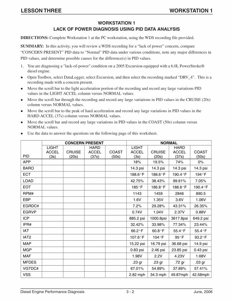
LESSON THREE WORKSTATION 1
Diesel Engine Performance Diagnosis 3 - 2 June, 2006
WORKSTATION 1LACK OF POWER DIAGNOSIS USING PID DATA ANALYSIS
DIRECTIONS: Complete Workstation 1 at the PC workstation, using the WDS recording file provided.
SUMMARY: In this activity, you will review a WDS recording for a “lack of power” concern, compare
“CONCERN PRESENT” PID data to “Normal” PID data under various conditions, note any major differences in
PID values, and determine possible causes for the difference(s) in PID values.
1. You are diagnosing a "lack-of-power" condition on a 2005 Excursion equipped with a 6.0L PowerStroke®diesel engine.
� Open Toolbox, select DataLogger, select Excursion, and then select the recording marked “DRV_4”. This is arecording made with a concern present.
� Move the scroll bar to the light acceleration portion of the recording and record any large variations PIDvalues in the LIGHT ACCEL column versus NORMAL values.
� Move the scroll bar through the recording and record any large variations in PID values in the CRUISE (20s)column versus NORMAL values.
� Move the scroll bar to the peak of hard acceleration and record any large variations in PID values in theHARD ACCEL (37s) column versus NORMAL values.
� Move the scroll bar and record any large variations in PID values in the COAST (50s) column versusNORMAL values.
� Use the data to answer the questions on the following page of this worksheet.
CONCERN PRESENT NORMAL
PID
LIGHTACCEL
(3s) CRUISE
(20s)
HARD ACCEL(37s)
COAST(50s)
LIGHTACCEL
(3s) CRUISE
(20s)
HARD ACCEL(37s)
COAST(50s)
APP 18% 19.5% 74% 0%
BARO 14.3 psi 14.3 psi 14.3 psi 14.3 psi
ECT 188.6ºF 188.6ºF 190.4ºF 194ºF
LOAD 42.75% 38.43% 99.61% 7.05%
EOT 185ºF 186.8ºF 188.6ºF 190.4ºF
RPM# 1143 1459 2846 890.5
EBP 1.6V 1.35V 3.6V 1.06V
EGRDC# 7.2% 29.28% 43.31% 26.35%
EGRVP 0.74V 1.04V 2.37V 0.88V
ICP 885.2 psi 1000.8psi 3617.8psi 649.2 psi
IPR# 32.42% 33.98% 77.34% 23.44%
IAT 66.2ºF 60.8ºF 55.4ºF 55.4ºF
IAT2 107.6ºF 104ºF 95ºF 93.2ºF
MAP 15.22 psi 16.79 psi 36.68 psi 14.9 psi
MGP 0.83 psi 2.46 psi 23.85 psi 0.43 psi
MAF 1.98V 2.2V 4.23V 1.68V
MFDES .23 gr .23 gr .72 gr .03 gr
VGTDC# 67.01% 54.89% 37.89% 57.41%
VSS 2.82 mph 34.3 mph 49.87mph 42.58mph
LESSON THREE WORKSTATION 1
Diesel Engine Performance Diagnosis 3 - 3 June, 2006
2. When comparing the two recordings, which PIDs are most affected by the concern?
_______________________________________________________________________________________
_______________________________________________________________________________________
3. Based on the MGP, IAT2 and MAF PID value, which subsystems are most affected by the concern?
_______________________________________________________________________________________
_______________________________________________________________________________________
4. Based on the MGP IAT2 and MAF PID values, which component would you check first for a concern?
_______________________________________________________________________________________
_______________________________________________________________________________________
5. What information leads you to believe that this component is the cause of the concern?
_______________________________________________________________________________________
_______________________________________________________________________________________
_______________________________________________________________________________________
_______________________________________________________________________________________
LESSON THREE WORKSTATION 2
Diesel Engine Performance Diagnosis 3 - 4 June, 2006
WORKSTATION 2LACK OF POWER DIAGNOSIS ON-VEHICLE
DIRECTIONS: Complete Workstation 2 at the VEHICLE workstation. Use the PC/ED and tools (WDS or IDS,
smoke machine, DMM and test light) available at this workstation to diagnose the concern.
SUMMARY: In this activity, you will use the necessary tools and service publications to diagnose a “lack of
power” concern on-vehicle, perform on-vehicle tests according to service publication procedures, and determine
root cause for the “lack of power” concern.
1. Go to QT1 in the PC/ED manual to begin your diagnosis.
� What effect would a leak in the exhaust system before the turbo have on the VGT system operation?
_______________________________________________________________________________________
2. Where in the intake system could a leak cause a lack of power condition?
_______________________________________________________________________________________
_______________________________________________________________________________________
3. Complete the diagnosis of this concern, filling in your steps and results below:
Test Step Result
LESSON THREE WORKSTATION 2
Diesel Engine Performance Diagnosis 3 - 5 June, 2006
4. What is the root cause of this concern?
_______________________________________________________________________________________
_______________________________________________________________________________________
5. What repair is required for this vehicle, based on your diagnosis?
_______________________________________________________________________________________
6. What steps are required after completing the repair?
_______________________________________________________________________________________
_______________________________________________________________________________________
_______________________________________________________________________________________
Return the workstation to the way you found it for the next group.
LESSON THREE WORKSTATION 3
Diesel Engine Performance Diagnosis 3 - 6 June, 2006
WORKSTATION 3RUNS ROUGH DIAGNOSIS USING PID DATA ANALYSIS
DIRECTIONS: Complete Workstation 3 at the PC workstation, using the recording file on the course CD-
ROM.
SUMMARY: You are diagnosing a "runs rough/surge" condition using a WDS recording.
1. Open a WDS session and view Previous Recording: ROUGHRUN.
� The graph view sizes may need to be adjusted for clarity. Be sure to look at the Power Balance portionof this recording, in addition to Datalogger.
� What bank is more affected by the concern?
_______________________________________________________________________________________
_______________________________________________________________________________________
2. At what RPM is the condition occurring?
_______________________________________________________________________________________
_______________________________________________________________________________________
3. What is the ICP voltage PID value and is it constant? (Graph view may need to be rescaled for clarity.)
_______________________________________________________________________________________
_______________________________________________________________________________________
4. How does ICP affect injector fuel delivery?
_______________________________________________________________________________________
_______________________________________________________________________________________
_______________________________________________________________________________________
5. Based on the recording, what component in the high pressure oil system could cause the ICP to beerratic?
_______________________________________________________________________________________
6. What is required to finish the repair?
_______________________________________________________________________________________
_______________________________________________________________________________________
_______________________________________________________________________________________
_______________________________________________________________________________________
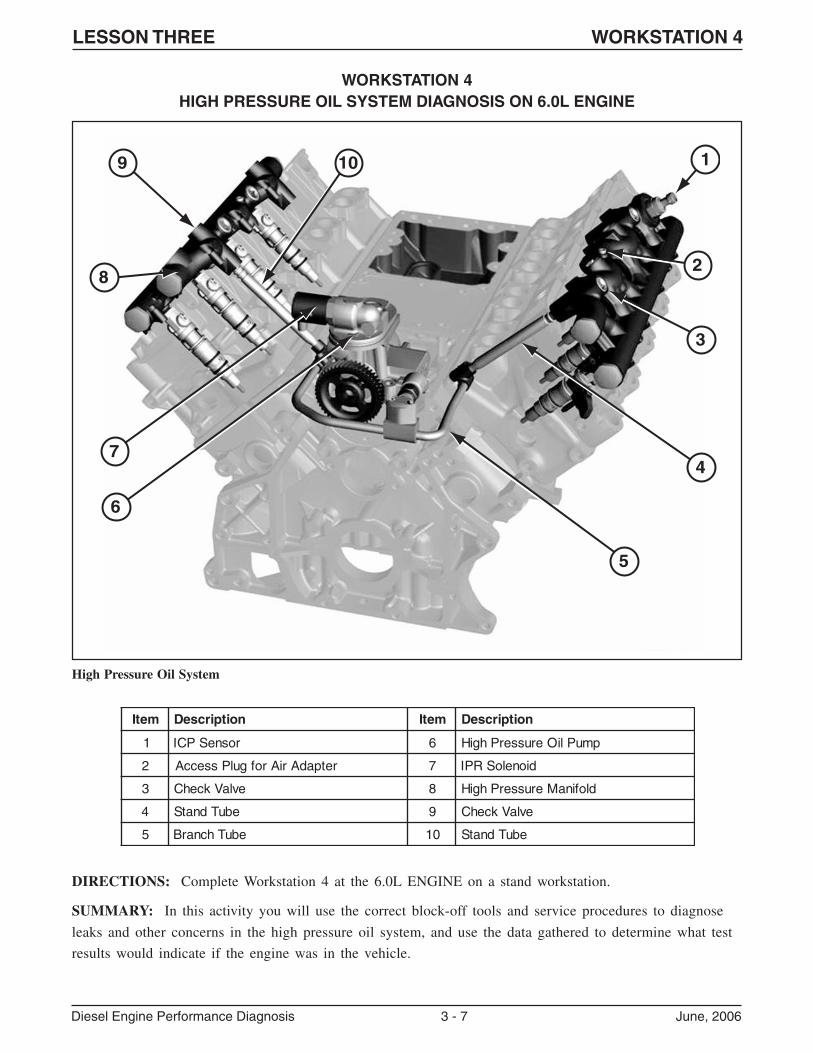
LESSON THREE WORKSTATION 4
Diesel Engine Performance Diagnosis 3 - 7 June, 2006
WORKSTATION 4HIGH PRESSURE OIL SYSTEM DIAGNOSIS ON 6.0L ENGINE
DIRECTIONS: Complete Workstation 4 at the 6.0L ENGINE on a stand workstation.
SUMMARY: In this activity you will use the correct block-off tools and service procedures to diagnose
leaks and other concerns in the high pressure oil system, and use the data gathered to determine what test
results would indicate if the engine was in the vehicle.
High Pressure Oil System
1
5
4
3
2
9 10
8
7
6
metI noitpircseD metI noitpircseD
1 rosneSPCI 6 pmuPliOerusserPhgiH
2 retpadAriArofgulPsseccA 7 dioneloSRPI
3 evlaVkcehC 8 dlofinaMerusserPhgiH
4 ebuTdnatS 9 evlaVkcehC
5 ebuThcnarB 01 ebuTdnatS
LESSON THREE WORKSTATION 4
Diesel Engine Performance Diagnosis 3 - 8 June, 2006
� Normally, you would crank the engine to see if pressure builds. For this activity, with the engine on thestand, you will use shop air to check for leaks.
� When performing high pressure oil testing on-vehicle with the engine OFF, the IPR is open (bypassing oil)until commanded ON with the WDS. For this activity, use the 12V power supply and wire leads to commandthe IPR valve ON.
1. Remove the left valve cover and install an air line adapter to the high pressure manifold with the properadapter. A leak may be apparent in either side of the engine.
If air is heard on the right or left side only, what can you determine?
_______________________________________________________________________________________
_______________________________________________________________________________________
2. If air is heard on both sides, what does this mean?
_______________________________________________________________________________________
_______________________________________________________________________________________
� If an air leak cannot be heard with confidence, then proceed with an isolation process.
� The PID for IPR duty cycle can be monitored on vehicle as you isolate components. A drastic change in thevalue will show a leak area.
� A high pressure block off tool is used to isolate each of the high pressure manifold(s) from the rest of thesystem.
� The block off tools vary for different model years and are identified in your student book. If the ICP sensor isnot installed, install it and the electrical connector
� There are two block off tools: one is threaded for installing the ICP sensor into it, and the other is solidwithout a threaded hole.
� Remove the rear high pressure check valve from the high pressure manifold, and install the solid block offtool.
3. What would happen if you tried to use the block off tool in the front plug of the high pressure manifold?
_______________________________________________________________________________________
_______________________________________________________________________________________
� If on a vehicle, you would now crank the engine. If the engine started (on the unblocked four cylinders) or theICP voltage increased, a leak point has been located. If no change occurred, you would continue on the rightside.
LESSON THREE WORKSTATION 4
Diesel Engine Performance Diagnosis 3 - 9 June, 2006
� Replace the plug on the left side with the production fitting so high pressure oil will supply the high pressuremanifold while the right manifold is isolated.
� Install the block off tool with the threaded hole into the high pressure manifold.
4. If performing this test on vehicle, why would you not be able to read ICP pressure at this time?
_______________________________________________________________________________________
_______________________________________________________________________________________
_______________________________________________________________________________________
� Install ICP Sensor in tool.
� If you were on a vehicle, you would crank the engine at this time. If the engine starts, or if ICP pressureincreases, a leak point has been found.
� If there is no change in ICP pressure, the next step is to install the block off tool in the left side high pressuremanifold and retest.
5. If performing this test on a vehicle, can the engine start at this point? Why or why not?
_______________________________________________________________________________________
_______________________________________________________________________________________
6. What if ICP pressure now increases above 1000 psi while cranking?
_______________________________________________________________________________________
_______________________________________________________________________________________
� If there is still no change after these tests, the problem is likely a high pressure pump or a high pressuremanifold that is cracked or broken. With the block off tools in place, an air test may show this problem eventhough it was not apparent earlier. With the valve covers off, it will be obvious if there is a leak.
� Check the O-rings at the branch tube-to-high pressure manifold connections before further enginedisassembly.
� Install the valve cover and return workstation to its original condition.
LESSON THREE WORKSTATION 4
Diesel Engine Performance Diagnosis 3 - 10 June, 2006
NOTES:
LESSON FOUR WORKSTATIONS
Diesel Engine Performance Diagnosis 4 - 1 June, 2006
LESSON FOURWORKSTATIONS
Workstation: Summary:
1 PID data analysis activity in which students will view and analyze a WDS recording from a
2005 6.0L-equipped vehicle to determine the cause of a “lack of power” concern.
2 Hands-on activity at vehicle that requires students to use Service Publications, WDS, DVOM
and other necessary tools to diagnose a “lack of power” concern.
3 CMT activity in which students will diagnose the cause of an intermittent “Cranks/No Start”
concern in the “virtual shop” and fill in any necessary answers on the worksheet.
4 Hands-on activity at the 6.0L PowerStroke® diesel engine on the stand. In this activity,
students will remove four fuel injectors from one bank, determine if there are concerns with
any of the injectors, and answer questions on how to properly install the injectors per Service
Information procedures.
LESSON FOUR WORKSTATION 1
Diesel Engine Performance Diagnosis 4 - 2 June, 2006
WORKSTATION 1LACK OF POWER DIAGNOSIS USING PID DATA ANALYSIS
DIRECTIONS: Complete Workstation 1 at the PC workstation, using the recording file on the course CD-ROM
and the Service Information at the workstation.
SUMMARY: You are diagnosing a "lack of power" condition on a 2005 vehicle equipped with a 6.0L
PowerStroke® diesel engine,
� Open WDS. Go to Previous Session and view VDR recording: 5EA08267. Use Recording #1 ONLY.
� Assume for this workstation that a rationality check was done at start up to ensure the temperature sensors areall within a close reading of each other to eliminate a faulty EOT sensor.
1. What do you see that is abnormal?
_______________________________________________________________________________________
2. What is the ECT PID value compared to the EOT PID value?
_______________________________________________________________________________________
3. What does this tell us?
_______________________________________________________________________________________
4. Are the low power and high EOT readings connected?
_______________________________________________________________________________________
_______________________________________________________________________________________
5. How would you know if DTCs are set?
_______________________________________________________________________________________
6. If the cooling system is performing properly, the coolant is at the proper temperature, and the oil is at animproper temperature, what can we assume?
_______________________________________________________________________________________
7. What is likely causing the concern on this vehicle?
_______________________________________________________________________________________
8. How would you complete the repair on this vehicle?
_______________________________________________________________________________________
_______________________________________________________________________________________
_______________________________________________________________________________________
_______________________________________________________________________________________
_______________________________________________________________________________________
LESSON FOUR WORKSTATION 2
Diesel Engine Performance Diagnosis 4 - 3 June, 2006
WORKSTATION 2LACK OF POWER DIAGNOSIS ON-VEHICLE
DIRECTIONS: Complete Workstation 2 at the VEHICLE workstation. Use the PC/ED and tools (WDS, DMM
and test light) available at this workstation to diagnose the concern.
SUMMARY: The vehicle at this workstation has a “lack of power” concern. The Preliminary Checks found in
Symptom Chart 7 are listed below. Due to time restrictions in this classroom training session, assume that all the
Preliminary Checks have been performed and no concerns were located. Review the Preliminary Checks before
proceeding with Step 1.
Symptom Chart 7 Preliminary Checks:
� Confirm brakes are not dragging.
� Check for oil in coolant.
� Check engine oil level.
� Confirm acceptable SAE oil viscosity and API rating of oil.
� Confirm oil change within 12,070 km (7,500 miles).
� Check air intake system: check for intake restriction; check air filter restriction gauge/air filter.
� Check MAP sensor hose for leaks, blockage or disconnection.
� Check EP sensor tube for leaks, blockage or disconnection.
� Check intake system for leaks.
� Check for low boost condition
� Check for over boost condition
� Check for sufficient clean fuel.
� Check for air in fuel.
� Compare loaded weight of vehicle with performance expectations.
� Power monitor active.
� Transmission concerns.
LESSON FOUR WORKSTATION 2
Diesel Engine Performance Diagnosis 4 - 4 June, 2006
1. Starting with QT3, record your diagnostic steps and results in the table below.
2. Based on your results in the previous Pinpoint Test, what have you confirmed?
_______________________________________________________________________________________
_______________________________________________________________________________________
3. Where are the possible causes for the above condition?
_______________________________________________________________________________________
_______________________________________________________________________________________
4. What steps are required after completing the repair?
_______________________________________________________________________________________
_______________________________________________________________________________________
_______________________________________________________________________________________
spetScitsongaiD stluseR
LESSON FOUR WORKSTATION 3
Diesel Engine Performance Diagnosis 4 - 5 June, 2006
WORKSTATION 3CRANKS/NO START DIAGNOSIS IN "VIRTUAL SHOP"
DIRECTIONS: Complete Workstation 3 at the CMT (PC) workstation.
SUMMARY: In this activity, you will use the tools, tests and service publications in the virtual shop to diagnose
an intermittent “cranks/no start” concern, perform tests in the virtual shop as required by service publication
procedures, review test results to determine next steps, and determine the root cause of the intermittent “cranks/
no start” concern.
1. Select CMT Scenario 2 and review the repair order.
Have you verified the concern? If not, do so.
_______________________________________________________________________________________
2. Navigate to the PC/ED manual: Section 3 (Symptom Charts). List the first two steps for this concern.Assume any on-vehicle inspections in the “Note” under QT1 are OK (no concerns located).
_______________________________________________________________________________________
_______________________________________________________________________________________
3. How do you determine which SSM should be checked first?
_______________________________________________________________________________________
_______________________________________________________________________________________
4. List the chafing points identified in the related SSM:
_______________________________________________________________________________________
_______________________________________________________________________________________
_______________________________________________________________________________________
_______________________________________________________________________________________
_______________________________________________________________________________________
_______________________________________________________________________________________
_______________________________________________________________________________________
_______________________________________________________________________________________
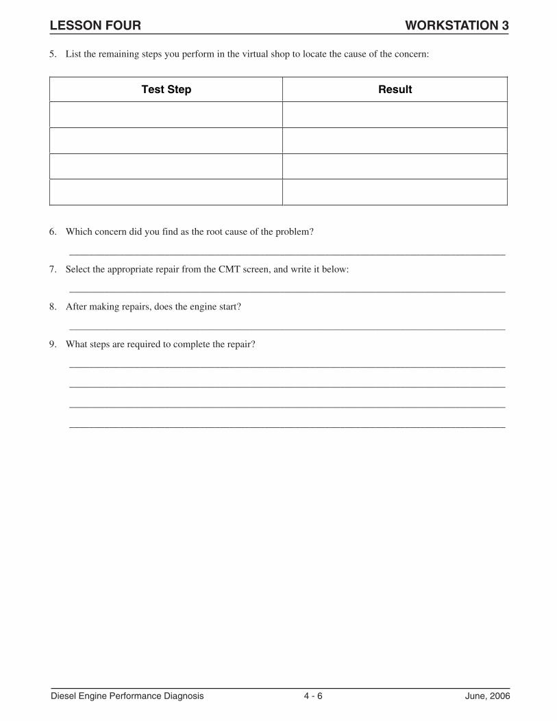
LESSON FOUR WORKSTATION 3
Diesel Engine Performance Diagnosis 4 - 6 June, 2006
5. List the remaining steps you perform in the virtual shop to locate the cause of the concern:
6. Which concern did you find as the root cause of the problem?
_______________________________________________________________________________________
7. Select the appropriate repair from the CMT screen, and write it below:
_______________________________________________________________________________________
8. After making repairs, does the engine start?
_______________________________________________________________________________________
9. What steps are required to complete the repair?
_______________________________________________________________________________________
_______________________________________________________________________________________
_______________________________________________________________________________________
_______________________________________________________________________________________
Test Step Result
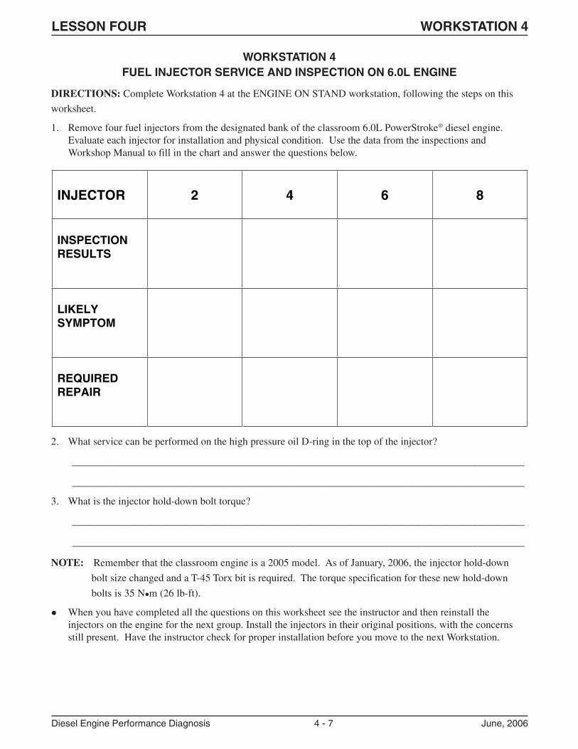
LESSON FOUR WORKSTATION 4
Diesel Engine Performance Diagnosis 4 - 7 June, 2006
WORKSTATION 4FUEL INJECTOR SERVICE AND INSPECTION ON 6.0L ENGINE
DIRECTIONS: Complete Workstation 4 at the ENGINE ON STAND workstation, following the steps on this
worksheet.
1. Remove four fuel injectors from the designated bank of the classroom 6.0L PowerStroke® diesel engine.Evaluate each injector for installation and physical condition. Use the data from the inspections andWorkshop Manual to fill in the chart and answer the questions below.
2. What service can be performed on the high pressure oil D-ring in the top of the injector?
_______________________________________________________________________________________
_______________________________________________________________________________________
3. What is the injector hold-down bolt torque?
_______________________________________________________________________________________
_______________________________________________________________________________________
NOTE: Remember that the classroom engine is a 2005 model. As of January, 2006, the injector hold-down
bolt size changed and a T-45 Torx bit is required. The torque specification for these new hold-down
bolts is 35 N�m (26 lb-ft).
� When you have completed all the questions on this worksheet see the instructor and then reinstall theinjectors on the engine for the next group. Install the injectors in their original positions, with the concernsstill present. Have the instructor check for proper installation before you move to the next Workstation.
INJECTOR 2 4 6 8
INSPECTIONRESULTS
LIKELYSYMPTOM
REQUIREDREPAIR

LESSON FOUR WORKSTATION 4
Diesel Engine Performance Diagnosis 4 - 8 June, 2006
NOTES:
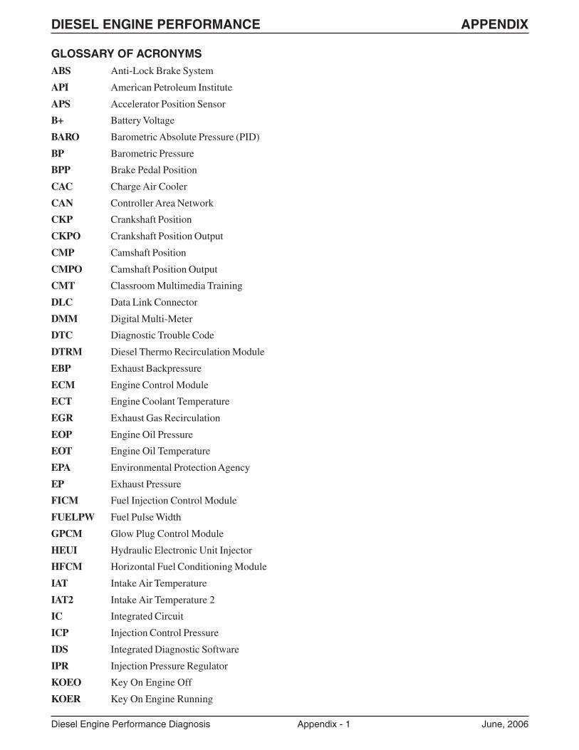
DIESEL ENGINE PERFORMANCE APPENDIX
Diesel Engine Performance Diagnosis Appendix - 1 June, 2006
GLOSSARY OF ACRONYMSABS Anti-Lock Brake System
API American Petroleum Institute
APS Accelerator Position Sensor
B+ Battery Voltage
BARO Barometric Absolute Pressure (PID)
BP Barometric Pressure
BPP Brake Pedal Position
CAC Charge Air Cooler
CAN Controller Area Network
CKP Crankshaft Position
CKPO Crankshaft Position Output
CMP Camshaft Position
CMPO Camshaft Position Output
CMT Classroom Multimedia Training
DLC Data Link Connector
DMM Digital Multi-Meter
DTC Diagnostic Trouble Code
DTRM Diesel Thermo Recirculation Module
EBP Exhaust Backpressure
ECM Engine Control Module
ECT Engine Coolant Temperature
EGR Exhaust Gas Recirculation
EOP Engine Oil Pressure
EOT Engine Oil Temperature
EPA Environmental Protection Agency
EP Exhaust Pressure
FICM Fuel Injection Control Module
FUELPW Fuel Pulse Width
GPCM Glow Plug Control Module
HEUI Hydraulic Electronic Unit Injector
HFCM Horizontal Fuel Conditioning Module
IAT Intake Air Temperature
IAT2 Intake Air Temperature 2
IC Integrated Circuit
ICP Injection Control Pressure
IDS Integrated Diagnostic Software
IPR Injection Pressure Regulator
KOEO Key On Engine Off
KOER Key On Engine Running
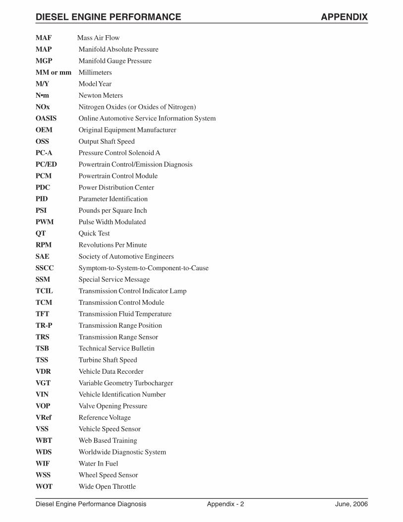
DIESEL ENGINE PERFORMANCE APPENDIX
Diesel Engine Performance Diagnosis Appendix - 2 June, 2006
MAF Mass Air Flow
MAP Manifold Absolute Pressure
MGP Manifold Gauge Pressure
MM or mm Millimeters
M/Y Model Year
N•m Newton Meters
NOx Nitrogen Oxides (or Oxides of Nitrogen)
OASIS Online Automotive Service Information System
OEM Original Equipment Manufacturer
OSS Output Shaft Speed
PC-A Pressure Control Solenoid A
PC/ED Powertrain Control/Emission Diagnosis
PCM Powertrain Control Module
PDC Power Distribution Center
PID Parameter Identification
PSI Pounds per Square Inch
PWM Pulse Width Modulated
QT Quick Test
RPM Revolutions Per Minute
SAE Society of Automotive Engineers
SSCC Symptom-to-System-to-Component-to-Cause
SSM Special Service Message
TCIL Transmission Control Indicator Lamp
TCM Transmission Control Module
TFT Transmission Fluid Temperature
TR-P Transmission Range Position
TRS Transmission Range Sensor
TSB Technical Service Bulletin
TSS Turbine Shaft Speed
VDR Vehicle Data Recorder
VGT Variable Geometry Turbocharger
VIN Vehicle Identification Number
VOP Valve Opening Pressure
VRef Reference Voltage
VSS Vehicle Speed Sensor
WBT Web Based Training
WDS Worldwide Diagnostic System
WIF Water In Fuel
WSS Wheel Speed Sensor
WOT Wide Open Throttle
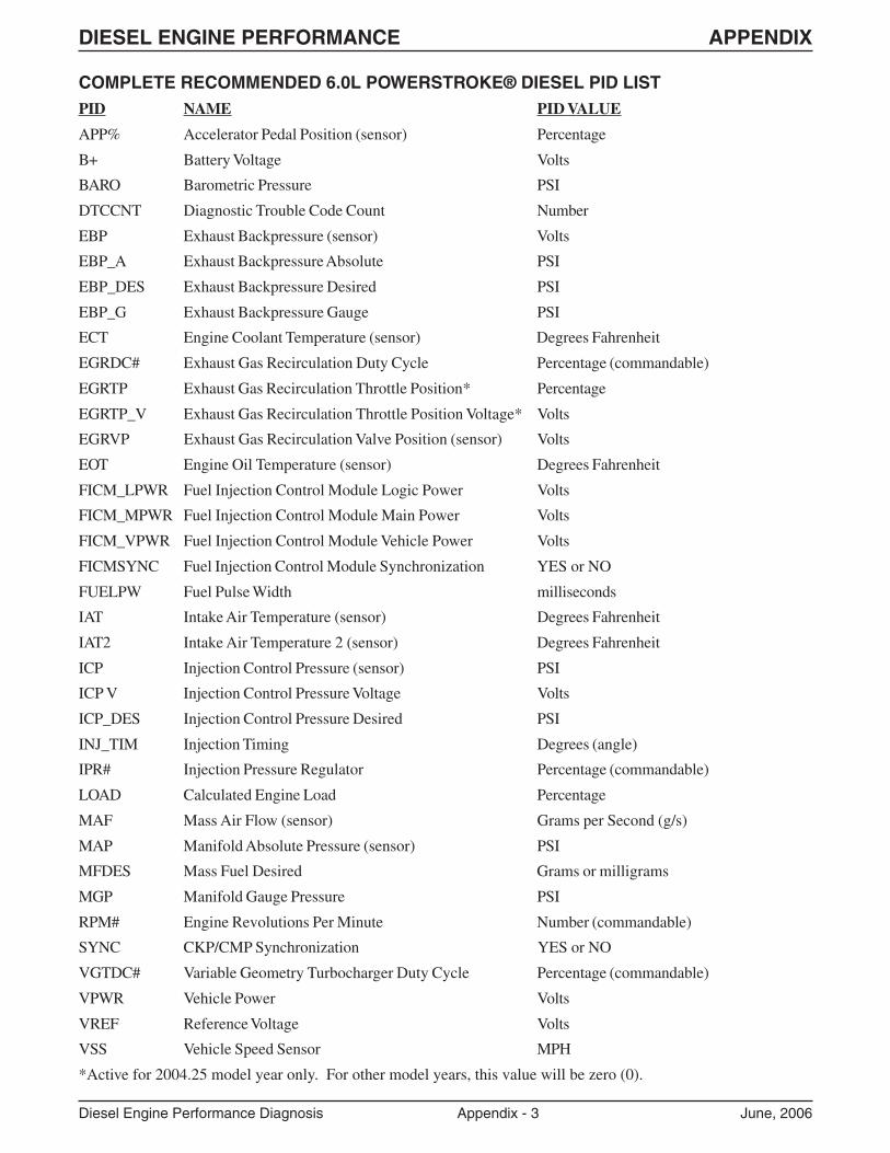
DIESEL ENGINE PERFORMANCE APPENDIX
Diesel Engine Performance Diagnosis Appendix - 3 June, 2006
COMPLETE RECOMMENDED 6.0L POWERSTROKE® DIESEL PID LISTPID NAME PID VALUE
APP% Accelerator Pedal Position (sensor) Percentage
B+ Battery Voltage Volts
BARO Barometric Pressure PSI
DTCCNT Diagnostic Trouble Code Count Number
EBP Exhaust Backpressure (sensor) Volts
EBP_A Exhaust Backpressure Absolute PSI
EBP_DES Exhaust Backpressure Desired PSI
EBP_G Exhaust Backpressure Gauge PSI
ECT Engine Coolant Temperature (sensor) Degrees Fahrenheit
EGRDC# Exhaust Gas Recirculation Duty Cycle Percentage (commandable)
EGRTP Exhaust Gas Recirculation Throttle Position* Percentage
EGRTP_V Exhaust Gas Recirculation Throttle Position Voltage* Volts
EGRVP Exhaust Gas Recirculation Valve Position (sensor) Volts
EOT Engine Oil Temperature (sensor) Degrees Fahrenheit
FICM_LPWR Fuel Injection Control Module Logic Power Volts
FICM_MPWR Fuel Injection Control Module Main Power Volts
FICM_VPWR Fuel Injection Control Module Vehicle Power Volts
FICMSYNC Fuel Injection Control Module Synchronization YES or NO
FUELPW Fuel Pulse Width milliseconds
IAT Intake Air Temperature (sensor) Degrees Fahrenheit
IAT2 Intake Air Temperature 2 (sensor) Degrees Fahrenheit
ICP Injection Control Pressure (sensor) PSI
ICP V Injection Control Pressure Voltage Volts
ICP_DES Injection Control Pressure Desired PSI
INJ_TIM Injection Timing Degrees (angle)
IPR# Injection Pressure Regulator Percentage (commandable)
LOAD Calculated Engine Load Percentage
MAF Mass Air Flow (sensor) Grams per Second (g/s)
MAP Manifold Absolute Pressure (sensor) PSI
MFDES Mass Fuel Desired Grams or milligrams
MGP Manifold Gauge Pressure PSI
RPM# Engine Revolutions Per Minute Number (commandable)
SYNC CKP/CMP Synchronization YES or NO
VGTDC# Variable Geometry Turbocharger Duty Cycle Percentage (commandable)
VPWR Vehicle Power Volts
VREF Reference Voltage Volts
VSS Vehicle Speed Sensor MPH
*Active for 2004.25 model year only. For other model years, this value will be zero (0).
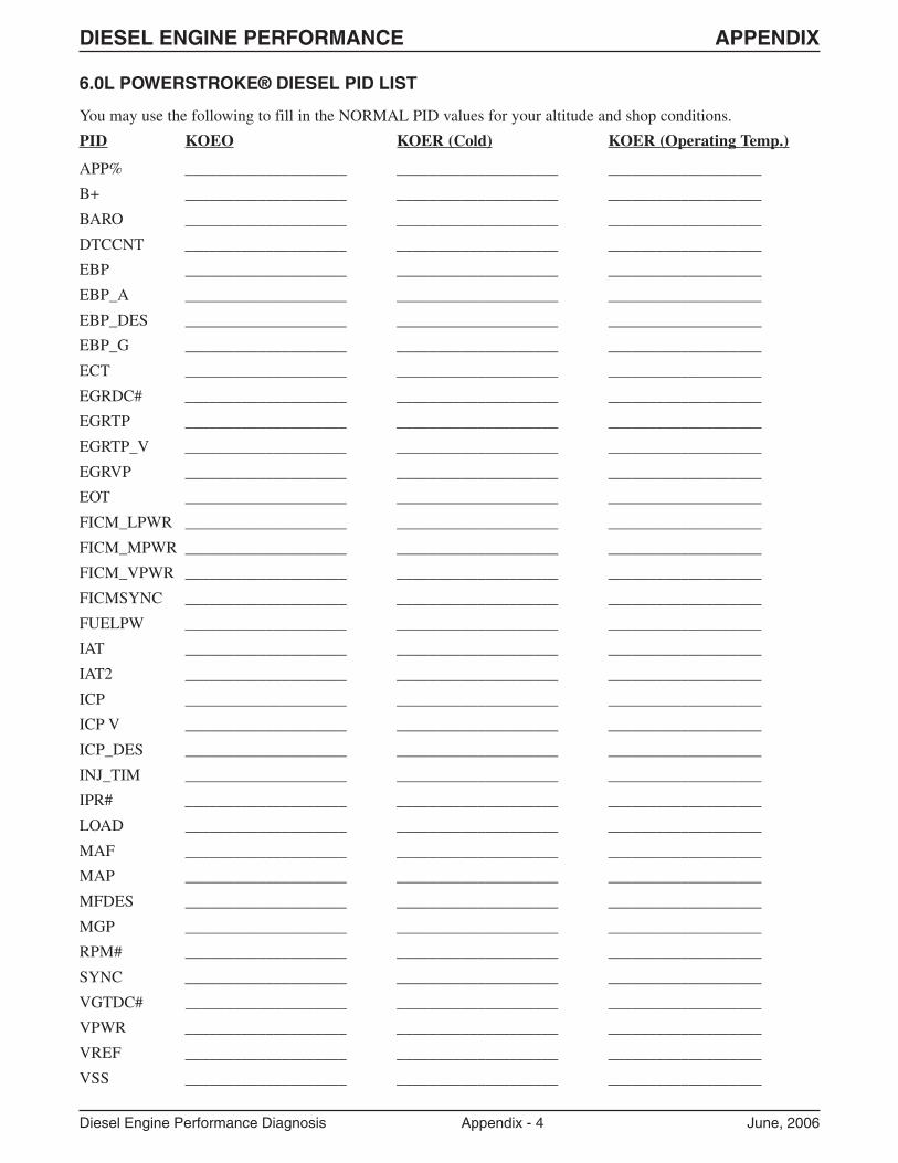
DIESEL ENGINE PERFORMANCE APPENDIX
Diesel Engine Performance Diagnosis Appendix - 4 June, 2006
6.0L POWERSTROKE® DIESEL PID LIST
You may use the following to fill in the NORMAL PID values for your altitude and shop conditions.
PID KOEO KOER (Cold) KOER (Operating Temp.)
APP% ____________________ ____________________ ___________________
B+ ____________________ ____________________ ___________________
BARO ____________________ ____________________ ___________________
DTCCNT ____________________ ____________________ ___________________
EBP ____________________ ____________________ ___________________
EBP_A ____________________ ____________________ ___________________
EBP_DES ____________________ ____________________ ___________________
EBP_G ____________________ ____________________ ___________________
ECT ____________________ ____________________ ___________________
EGRDC# ____________________ ____________________ ___________________
EGRTP ____________________ ____________________ ___________________
EGRTP_V ____________________ ____________________ ___________________
EGRVP ____________________ ____________________ ___________________
EOT ____________________ ____________________ ___________________
FICM_LPWR ____________________ ____________________ ___________________
FICM_MPWR ____________________ ____________________ ___________________
FICM_VPWR ____________________ ____________________ ___________________
FICMSYNC ____________________ ____________________ ___________________
FUELPW ____________________ ____________________ ___________________
IAT ____________________ ____________________ ___________________
IAT2 ____________________ ____________________ ___________________
ICP ____________________ ____________________ ___________________
ICP V ____________________ ____________________ ___________________
ICP_DES ____________________ ____________________ ___________________
INJ_TIM ____________________ ____________________ ___________________
IPR# ____________________ ____________________ ___________________
LOAD ____________________ ____________________ ___________________
MAF ____________________ ____________________ ___________________
MAP ____________________ ____________________ ___________________
MFDES ____________________ ____________________ ___________________
MGP ____________________ ____________________ ___________________
RPM# ____________________ ____________________ ___________________
SYNC ____________________ ____________________ ___________________
VGTDC# ____________________ ____________________ ___________________
VPWR ____________________ ____________________ ___________________
VREF ____________________ ____________________ ___________________
VSS ____________________ ____________________ ___________________
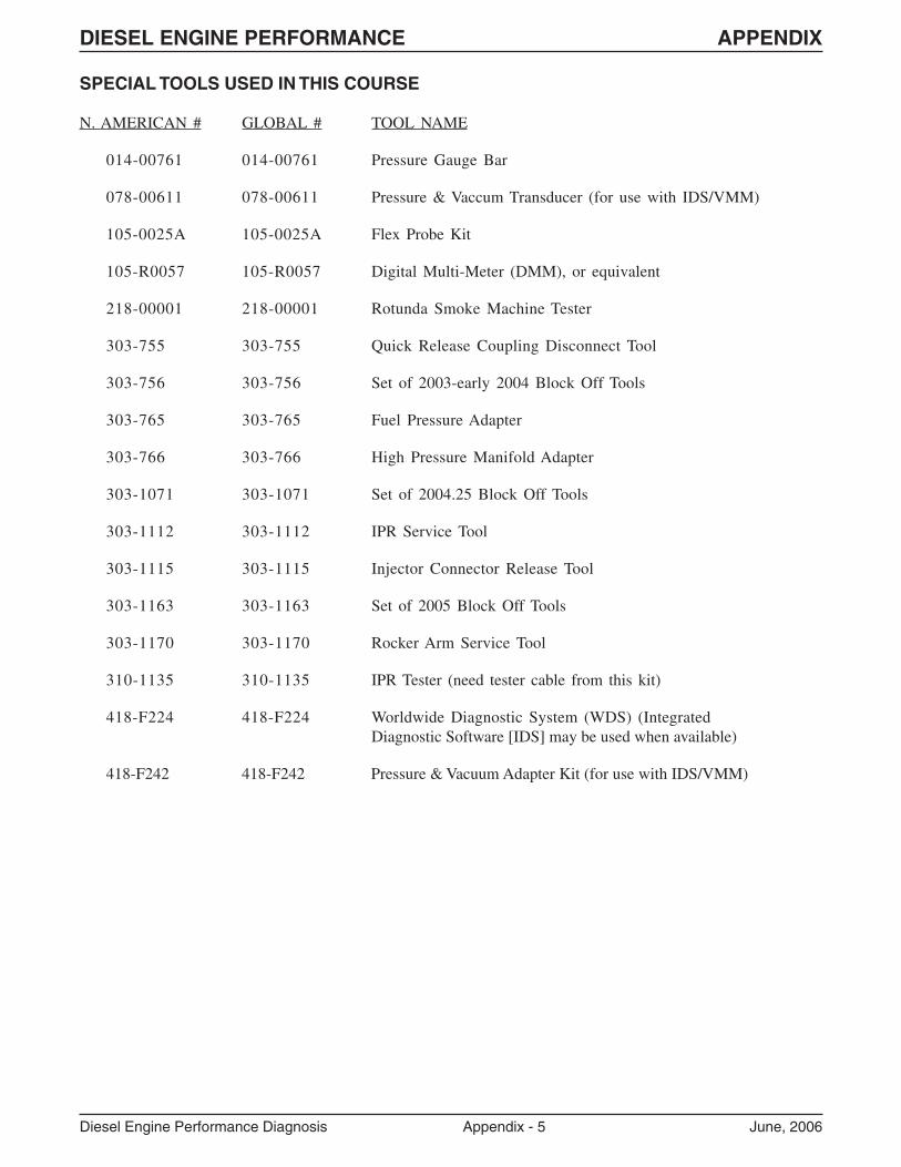
DIESEL ENGINE PERFORMANCE APPENDIX
Diesel Engine Performance Diagnosis Appendix - 5 June, 2006
SPECIAL TOOLS USED IN THIS COURSE
N. AMERICAN # GLOBAL # TOOL NAME
014-00761 014-00761 Pressure Gauge Bar
078-00611 078-00611 Pressure & Vaccum Transducer (for use with IDS/VMM)
105-0025A 105-0025A Flex Probe Kit
105-R0057 105-R0057 Digital Multi-Meter (DMM), or equivalent
218-00001 218-00001 Rotunda Smoke Machine Tester
303-755 303-755 Quick Release Coupling Disconnect Tool
303-756 303-756 Set of 2003-early 2004 Block Off Tools
303-765 303-765 Fuel Pressure Adapter
303-766 303-766 High Pressure Manifold Adapter
303-1071 303-1071 Set of 2004.25 Block Off Tools
303-1112 303-1112 IPR Service Tool
303-1115 303-1115 Injector Connector Release Tool
303-1163 303-1163 Set of 2005 Block Off Tools
303-1170 303-1170 Rocker Arm Service Tool
310-1135 310-1135 IPR Tester (need tester cable from this kit)
418-F224 418-F224 Worldwide Diagnostic System (WDS) (IntegratedDiagnostic Software [IDS] may be used when available)
418-F242 418-F242 Pressure & Vacuum Adapter Kit (for use with IDS/VMM)
DIESEL ENGINE PERFORMANCE APPENDIX
Diesel Engine Performance Diagnosis Appendix - 6 June, 2006
NOTES: