Embed Size (px)
Citation preview
DOE Fundamentals
MECHANICAL SCIENCE
Module 1
Diesel Engine Fundamentals
Mechanical Science Diesel Engine Fundamentals
MS-01-ii
TABLE OF CONTENTS
TABLE OF CONTENTS .............................................................................................................. ii
LIST OF FIGURES .................................................................................................................... iv
LIST OF TABLES ....................................................................................................................... vi
REFERENCES ......................................................................................................................... vii
OBJECTIVES .......................................................................................................................... viii
DIESEL ENGINES ..................................................................................................................... 1
Introduction ............................................................................................................................ 1
History .................................................................................................................................... 2
Diesel Engines ....................................................................................................................... 2
Major Components of a Diesel Engine.................................................................................... 3
The Cylinder Block ................................................................................................................. 5
Crankcase and Oil Pan ........................................................................................................... 6
Cylinder Sleeve or Bore .......................................................................................................... 6
Piston and Piston Rings ......................................................................................................... 7
Connecting Rod ...................................................................................................................... 7
Crankshaft .............................................................................................................................. 7
Flywheel ................................................................................................................................. 8
Cylinder Heads and Valves .................................................................................................... 9
Timing Gears, Camshaft, and Valve Mechanism ................................................................... 9
Blower ...................................................................................................................................11
Diesel Engine Support Systems ............................................................................................11
Exhaust System ....................................................................................................................15
Operational Terminology .......................................................................................................15
Bore and Stroke ....................................................................................................................15
Summary ..................................................................................................................................17
FUNDAMENTALS OF THE DIESEL CYCLE ............................................................................18
The Basic Diesel Cycles ........................................................................................................18
The Four-Stoke Cycle ............................................................................................................19
The Two-Stroke Cycle ...........................................................................................................22
Summary ..................................................................................................................................24
Mechanical Science Diesel Engine Fundamentals
MS-01-iii
DIESEL ENGINE SPEED, FUEL CONTROLS, AND PROTECTION ........................................26
Engine Control .......................................................................................................................26
Fuel Injectors .........................................................................................................................26
Governor ...............................................................................................................................29
Operation of a Governor ........................................................................................................30
Starting Circuits .....................................................................................................................32
Engine Protection ..................................................................................................................33
Summary ..................................................................................................................................35
Mechanical Science Diesel Engine Fundamentals
MS-01-iv
LIST OF FIGURES
Figure 1 Example of a Large Skid-Mounted, Diesel-Driven Generator ...................................... 2
Figure 2 Cutaway of a Four-Stroke Supercharged Diesel Engine .............................................. 4
Figure 3 Cross Section of a V-type Four Stroke Diesel Engine ................................................. 5
Figure 4 The Cylinder Block ....................................................................................................... 5
Figure 5 Diesel Engine Wet Cylinder Sleeve ............................................................................. 6
Figure 6 Piston and Piston Rod ................................................................................................. 7
Figure 7 Diesel Engine Crankshaft and Bearings ...................................................................... 8
Figure 8 Diesel Engine Valve .................................................................................................... 9
Figure 9 Diesel Engine Camshaft and Drive Gear ..................................................................... 9
Figure 10 Diesel Engine Valve Train ....................................................................................... 10
Figure 11 Diesel Engine Cooling System ................................................................................ 11
Figure 12 Diesel Engine Internal Lubrication System .............................................................. 12
Figure 13 Diesel Engine Fuel Flowpath ................................................................................... 13
Figure 14 Oil Bath Air Filter ..................................................................................................... 14
Figure 15 Compression Ratio .................................................................................................. 16
Figure 16 Scavenging and Intake ............................................................................................ 19
Figure 17 Compression ........................................................................................................... 20
Figure 18 Fuel Injection ........................................................................................................... 20
Figure 19 Power ....................................................................................................................... 21
Figure 20 Exhaust ................................................................................................................... 21
Figure 21 2-Stroke Exhaust ..................................................................................................... 22
Figure 22 2-Stroke Intake ........................................................................................................ 22
Figure 23 2-Stroke Compression ............................................................................................. 23
Figure 24 2-Stroke Fuel Injection ............................................................................................ 23
Figure 25 2-Stroke Power ....................................................................................................... 23

Mechanical Science Diesel Engine Fundamentals
MS-01-v
Figure 26 Fuel Injector Cutaway ............................................................................................. 27
Figure 27 Fuel Injector Plunger ............................................................................................... 28
Figure 28 Simplified Mechanical-Hydraulic Governor .............................................................. 30
Figure 29 Cutaway of a Woodward Governor .......................................................................... 31

Mechanical Science Diesel Engine Fundamentals
MS-01-vi
LIST OF TABLES
NONE
Mechanical Science Diesel Engine Fundamentals
MS-01-vii
REFERENCES
Benson & Whitehouse, Internal Combustion Engines, Pergamon.
Cheremisinoff, N. P., Fluid Flow, Pumps, Pipes and Channels, Ann Arbor Science.
Scheel, Gas and Air Compression Machinery, McGraw/Hill.
Skrotzki and Vopat, Steam and Gas Turbines, McGraw/Hill.
Stinson, Karl W., Diesel Engineering Handbook, Diesel Publications Incorporated.
Mechanical Science Diesel Engine Fundamentals
MS-01-viii
OBJECTIVES
TERMINAL OBJECTIVE
1.0 Without references, DESCRIBE the components and theory of operation for a diesel
engine.
ENABLING OBJECTIVES
1.1 DEFINE the following diesel engine terms:
a. Compression ratio
b. Bore
c. Stroke
d. Combustion chamber
1.2 Given a drawing of a diesel engine, IDENTIFY the following:
a. Piston/rod e. Intake ports or valve(s)
b. Cylinder f. Exhaust ports or valve(s)
c. Blower g. Fuel injector
d. Crankshaft
1.3 EXPLAIN how a diesel engine converts the chemical energy stored in the diesel fuel into
mechanical energy.
1.4 EXPLAIN how the ignition process occurs in a diesel engine.
1.5 EXPLAIN the operation of a 4-cycle diesel engine to include when the following events
occur during a cycle:
a. Intake d. Compression
b. Exhaust e. Power
c. Fuel injection
1.6 EXPLAIN the operation of a 2-cycle diesel engine, including when the following events
occur during a cycle:
a. Intake d. Compression
b. Exhaust e. Power
c. Fuel injection
1.7 DESCRIBE how the mechanical-hydraulic governor on a diesel engine controls engine
speed.
1.8 LIST five protective alarms usually found on mid-sized and larger diesel engines.
Mechanical Science Diesel Engine Fundamentals
MS-01-1
DIESEL ENGINES
One of the most common prime movers is the diesel engine. Before gaining an
understanding of how the engine operates a basic understanding of the engine's
components should be gained. This chapter reviews the major components of a
generic diesel engine.
EO 1.1 DEFINE the following diesel engine terms:
a. Compression ratio
b. Bore
c. Stroke
d. Combustion chamber
EO 1.2 Given a drawing of a diesel engine, IDENTIFY the following:
a. Piston/rod e. Intake ports or valve(s)
b. Cylinder f. Exhaust ports or valve(s)
c. Blower g. Fuel injector
d. Crankshaft
Introduction
Most DOE facilities require some type of prime mover to supply mechanical power for pumping,
electrical power generation, operation of heavy equipment, and to act as a backup electrical
generator for emergency use during the loss of the normal power source. Although several
types of prime movers are available (gasoline engines, steam and gas turbines), the diesel
engine is the most commonly used. Diesel engines provide a self-reliant energy source that is
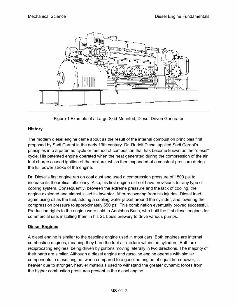
available in sizes from a few horsepower to 10,000 hp. Figure 1 provides an illustration of a
common skid-mounted, diesel-driven generator. Relatively speaking, diesel engines are small,
inexpensive, powerful, fuel efficient, and extremely reliable if maintained properly.
Because of the widespread use of diesel engines at DOE facilities, a basic understanding of the
operation of a diesel engine will help ensure they are operated and maintained properly. Due to
the large variety of sizes, brands, and types of engines in service, this module is intended to
provide the fundamentals and theory of operation of a diesel engine. Specific information on a
particular engine should be obtained from the vendor's manual.
Mechanical Science Diesel Engine Fundamentals
MS-01-2
Figure 1 Example of a Large Skid-Mounted, Diesel-Driven Generator
History
The modern diesel engine came about as the result of the internal combustion principles first
proposed by Sadi Carnot in the early 19th century. Dr. Rudolf Diesel applied Sadi Carnot's
principles into a patented cycle or method of combustion that has become known as the "diesel"
cycle. His patented engine operated when the heat generated during the compression of the air
fuel charge caused ignition of the mixture, which then expanded at a constant pressure during
the full power stroke of the engine.
Dr. Diesel's first engine ran on coal dust and used a compression pressure of 1500 psi to
increase its theoretical efficiency. Also, his first engine did not have provisions for any type of
cooling system. Consequently, between the extreme pressure and the lack of cooling, the
engine exploded and almost killed its inventor. After recovering from his injuries, Diesel tried
again using oil as the fuel, adding a cooling water jacket around the cylinder, and lowering the
compression pressure to approximately 550 psi. This combination eventually proved successful.
Production rights to the engine were sold to Adolphus Bush, who built the first diesel engines for
commercial use, installing them in his St. Louis brewery to drive various pumps.
Diesel Engines
A diesel engine is similar to the gasoline engine used in most cars. Both engines are internal
combustion engines, meaning they burn the fuel-air mixture within the cylinders. Both are
reciprocating engines, being driven by pistons moving laterally in two directions. The majority of
their parts are similar. Although a diesel engine and gasoline engine operate with similar
components, a diesel engine, when compared to a gasoline engine of equal horsepower, is
heavier due to stronger, heavier materials used to withstand the greater dynamic forces from
the higher combustion pressures present in the diesel engine.
Mechanical Science Diesel Engine Fundamentals
MS-01-3
The greater combustion pressure is the result of the higher compression ratio used by diesel
engines. The compression ratio is a measure of how much the engine compresses the gasses
in the engine's cylinder. In a gasoline engine the compression ratio (which controls the
compression temperature) is limited by the air-fuel mixture entering the cylinders. The lower
ignition temperature of gasoline will cause it to ignite (burn) at a compression ratio of less than
10:1. The average car has a 7:1 compression ratio. In a diesel engine, compression ratios
ranging from 14:1 to as high as 24:1 are commonly used. The higher compression ratios are
possible because only air is compressed, and then the fuel is injected. This is one of the factors
that allows the diesel engine to be so efficient. Compression ratio will be discussed in greater
detail later in this module.
Another difference between a gasoline engine and a diesel engine is the manner in which
engine speed is controlled. In any engine, speed (or power) is a direct function of the amount of
fuel burned in the cylinders. Gasoline engines are self-speed-limiting, due to the method the
engine uses to control the amount of air entering the engine. Engine speed is indirectly
controlled by the butterfly valve in the carburetor. The butterfly valve in a carburetor limits the
amount of air entering the engine. In a carburetor, the rate of air flow dictates the amount of
gasoline that will be mixed with the air. Limiting the amount of air entering the engine limits the
amount of fuel entering the engine, and, therefore, limits the speed of the engine. By limiting the
amount of air entering the engine, adding more fuel does not increase engine speed beyond the
point where the fuel burns 100% of the available air (oxygen).
Diesel engines are not self-speed-limiting because the air (oxygen) entering the engine is
always the maximum amount. Therefore, the engine speed is limited solely by the amount of
fuel injected into the engine cylinders. Therefore, the engine always has sufficient oxygen to
burn and the engine will attempt to accelerate to meet the new fuel injection rate. Because of
this, a manual fuel control is not possible because these engines, in an unloaded condition, can
accelerate at a rate of more than 2000 revolutions per second. Diesel engines require a speed
limiter, commonly called the governor, to control the amount of fuel being injected into the
engine.
Unlike a gasoline engine, a diesel engine does not require an ignition system because in a
diesel engine the fuel is injected into the cylinder as the piston comes to the top of its
compression stroke. When fuel is injected, it vaporizes and ignites due to the heat created by
the compression of the air in the cylinder.
Major Components of a Diesel Engine
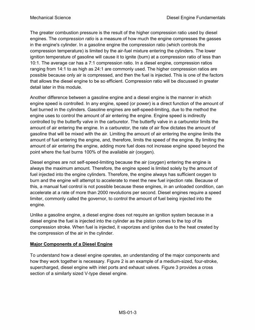
To understand how a diesel engine operates, an understanding of the major components and
how they work together is necessary. Figure 2 is an example of a medium-sized, four-stroke,
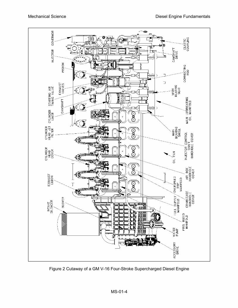
supercharged, diesel engine with inlet ports and exhaust valves. Figure 3 provides a cross
section of a similarly sized V-type diesel engine.
Mechanical Science Diesel Engine Fundamentals
MS-01-4
Figure 2 Cutaway of a GM V-16 Four-Stroke Supercharged Diesel Engine
Mechanical Science Diesel Engine Fundamentals
MS-01-5
Figure 3 Cross Section of a V-type
Four Stroke Diesel Engine
The Cylinder Block
The cylinder block, as shown in
Figure 4, is generally a single unit
made from cast iron. In a liquid-
cooled diesel, the block also
provides the structure and rigid
frame for the engine's cylinders,
water coolant and oil passages,
and support for the crankshaft and
camshaft bearings.
Figure 4 The Cylinder Block
Mechanical Science Diesel Engine Fundamentals
MS-01-6
Crankcase and Oil Pan
The crankcase is usually located on the bottom of the cylinder block. The crankcase is defined
as the area around the crankshaft and crankshaft bearings. This area encloses the rotating
crankshaft and crankshaft counter weights and directs returning oil into the oil pan. The oil pan
is located at the bottom of the crankcase as shown in Figure 2 and Figure 3. The oil pan collects
and stores the engine's supply of lubricating oil. Large diesel engines may have the oil pan
divided into several separate pans.
Cylinder Sleeve or Bore
Diesel engines use one of two types of cylinders. In one type, each cylinder is simply machined
or bored into the block casting, making the block and cylinders an integral part. In the second
type, a machined steel sleeve is pressed into the block casting to form the cylinder. Figure 2
and Figure 3 provide examples of sleeved diesel engines. With either method, the cylinder
sleeve or bore provides the engine with the cylindrical structure needed to confine the
combustion gasses and to act as a guide for the engine's pistons.
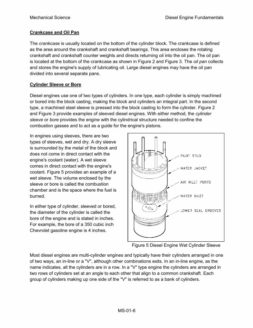
In engines using sleeves, there are two
types of sleeves, wet and dry. A dry sleeve
is surrounded by the metal of the block and
does not come in direct contact with the
engine's coolant (water). A wet sleeve
comes in direct contact with the engine's
coolant. Figure 5 provides an example of a
wet sleeve. The volume enclosed by the
sleeve or bore is called the combustion
chamber and is the space where the fuel is
burned.
In either type of cylinder, sleeved or bored,
the diameter of the cylinder is called the
bore of the engine and is stated in inches.
For example, the bore of a 350 cubic inch
Chevrolet gasoline engine is 4 inches.
Figure 5 Diesel Engine Wet Cylinder Sleeve
Most diesel engines are multi-cylinder engines and typically have their cylinders arranged in one
of two ways, an in-line or a "V", although other combinations exits. In an in-line engine, as the
name indicates, all the cylinders are in a row. In a "V" type engine the cylinders are arranged in
two rows of cylinders set at an angle to each other that align to a common crankshaft. Each
group of cylinders making up one side of the "V" is referred to as a bank of cylinders.
Mechanical Science Diesel Engine Fundamentals
MS-01-7
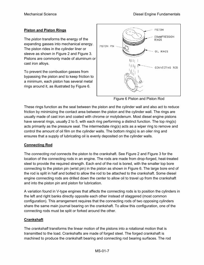
Piston and Piston Rings
The piston transforms the energy of the
expanding gasses into mechanical energy.
The piston rides in the cylinder liner or
sleeve as shown in Figure 2 and Figure 3.
Pistons are commonly made of aluminum or
cast iron alloys.
To prevent the combustion gasses from
bypassing the piston and to keep friction to
a minimum, each piston has several metal
rings around it, as illustrated by Figure 6.
Figure 6 Piston and Piston Rod
These rings function as the seal between the piston and the cylinder wall and also act to reduce
friction by minimizing the contact area between the piston and the cylinder wall. The rings are
usually made of cast iron and coated with chrome or molybdenum. Most diesel engine pistons
have several rings, usually 2 to 5, with each ring performing a distinct function. The top ring(s)
acts primarily as the pressure seal. The intermediate ring(s) acts as a wiper ring to remove and
control the amount of oil film on the cylinder walls. The bottom ring(s) is an oiler ring and
ensures that a supply of lubricating oil is evenly deposited on the cylinder walls.
Connecting Rod
The connecting rod connects the piston to the crankshaft. See Figure 2 and Figure 3 for the
location of the connecting rods in an engine. The rods are made from drop-forged, heat-treated
steel to provide the required strength. Each end of the rod is bored, with the smaller top bore
connecting to the piston pin (wrist pin) in the piston as shown in Figure 6. The large bore end of
the rod is split in half and bolted to allow the rod to be attached to the crankshaft. Some diesel
engine connecting rods are drilled down the center to allow oil to travel up from the crankshaft
and into the piston pin and piston for lubrication.
A variation found in V-type engines that affects the connecting rods is to position the cylinders in
the left and right banks directly opposite each other instead of staggered (most common
configuration). This arrangement requires that the connecting rods of two opposing cylinders
share the same main journal bearing on the crankshaft. To allow this configuration, one of the
connecting rods must be split or forked around the other.
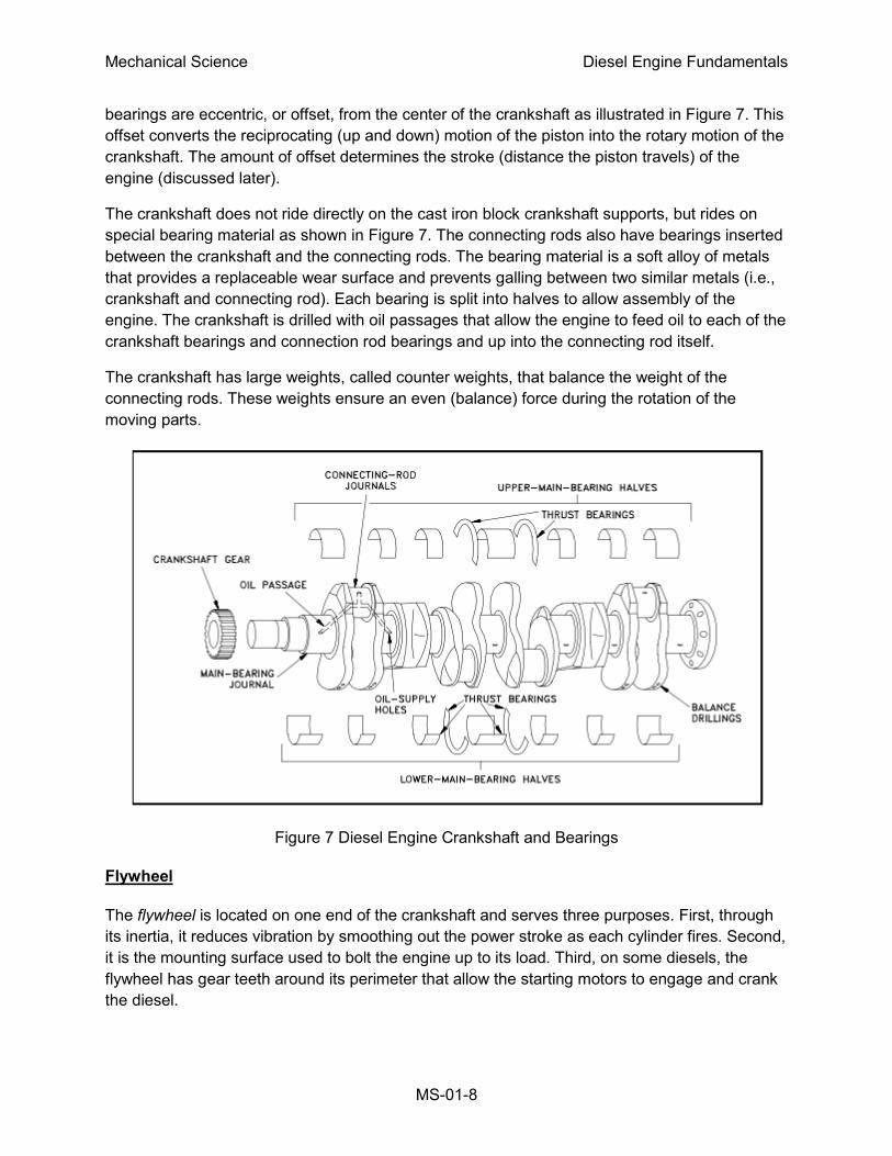
Crankshaft
The crankshaft transforms the linear motion of the pistons into a rotational motion that is
transmitted to the load. Crankshafts are made of forged steel. The forged crankshaft is
machined to produce the crankshaft bearing and connecting rod bearing surfaces. The rod
Mechanical Science Diesel Engine Fundamentals
MS-01-8
bearings are eccentric, or offset, from the center of the crankshaft as illustrated in Figure 7. This
offset converts the reciprocating (up and down) motion of the piston into the rotary motion of the
crankshaft. The amount of offset determines the stroke (distance the piston travels) of the
engine (discussed later).
The crankshaft does not ride directly on the cast iron block crankshaft supports, but rides on
special bearing material as shown in Figure 7. The connecting rods also have bearings inserted
between the crankshaft and the connecting rods. The bearing material is a soft alloy of metals
that provides a replaceable wear surface and prevents galling between two similar metals (i.e.,
crankshaft and connecting rod). Each bearing is split into halves to allow assembly of the
engine. The crankshaft is drilled with oil passages that allow the engine to feed oil to each of the
crankshaft bearings and connection rod bearings and up into the connecting rod itself.
The crankshaft has large weights, called counter weights, that balance the weight of the
connecting rods. These weights ensure an even (balance) force during the rotation of the
moving parts.
Figure 7 Diesel Engine Crankshaft and Bearings
Flywheel
The flywheel is located on one end of the crankshaft and serves three purposes. First, through
its inertia, it reduces vibration by smoothing out the power stroke as each cylinder fires. Second,
it is the mounting surface used to bolt the engine up to its load. Third, on some diesels, the
flywheel has gear teeth around its perimeter that allow the starting motors to engage and crank
the diesel.
Mechanical Science Diesel Engine Fundamentals
MS-01-9
Cylinder Heads and Valves
A diesel engine's cylinder heads perform several functions. First, they provide the top seal for
the cylinder bore or sleeve. Second, they provide the structure holding exhaust valves (and
intake valves where applicable), the fuel injector, and necessary linkages. A diesel engine's
heads are manufactured in one of two ways. In one method, each cylinder has its own head
casting, which is bolted to the block. This method is used primarily on the larger diesel engines.
In the second method, which is used on
smaller engines, the engine's head is cast as
one piece (multi-cylinder head).
Diesel engines have two methods of admitting
and exhausting gasses from the cylinder. They
can use either ports or valves or a
combination of both. Ports are slots in the
cylinder walls located in the lower 1/3 of the
bore. See Figure 2 and Figure 3 for examples
of intake ports, and note their relative location
with respect to the rest of the engine. When
the piston travels below the level of the ports,
the ports are "opened" and fresh air or exhaust
gasses are able to enter or leave, depending
on the type of port.
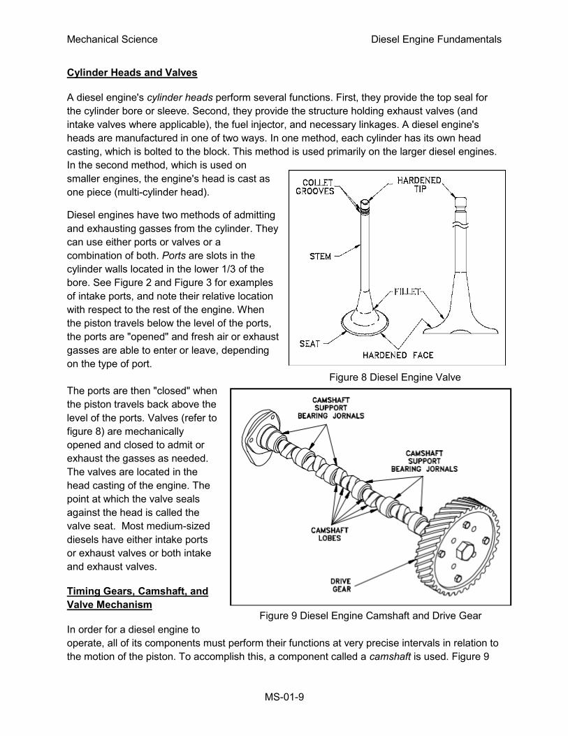
Figure 8 Diesel Engine Valve
The ports are then "closed" when
the piston travels back above the
level of the ports. Valves (refer to
figure 8) are mechanically
opened and closed to admit or
exhaust the gasses as needed.
The valves are located in the
head casting of the engine. The
point at which the valve seals
against the head is called the
valve seat. Most medium-sized
diesels have either intake ports
or exhaust valves or both intake
and exhaust valves.
Timing Gears, Camshaft, and
Valve Mechanism
In order for a diesel engine to
operate, all of its components must perform their functions at very precise intervals in relation to
the motion of the piston. To accomplish this, a component called a camshaft is used. Figure 9
Figure 9 Diesel Engine Camshaft and Drive Gear
Mechanical Science Diesel Engine Fundamentals
MS-01-10
illustrates a camshaft and camshaft drive gear. Figure 2 and Figure 3 illustrate the location of a
camshaft in a large overhead cam diesel engine.
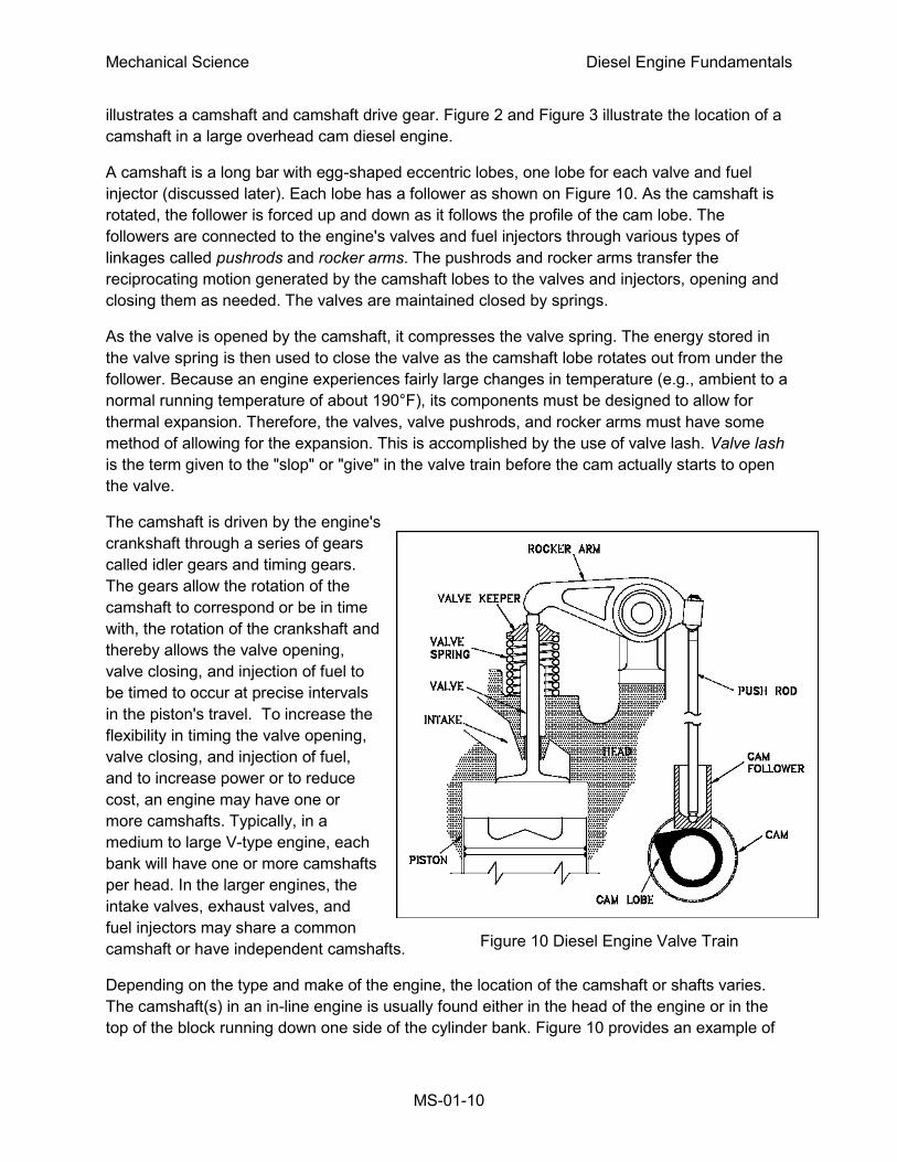
A camshaft is a long bar with egg-shaped eccentric lobes, one lobe for each valve and fuel
injector (discussed later). Each lobe has a follower as shown on Figure 10. As the camshaft is
rotated, the follower is forced up and down as it follows the profile of the cam lobe. The
followers are connected to the engine's valves and fuel injectors through various types of
linkages called pushrods and rocker arms. The pushrods and rocker arms transfer the
reciprocating motion generated by the camshaft lobes to the valves and injectors, opening and
closing them as needed. The valves are maintained closed by springs.
As the valve is opened by the camshaft, it compresses the valve spring. The energy stored in
the valve spring is then used to close the valve as the camshaft lobe rotates out from under the
follower. Because an engine experiences fairly large changes in temperature (e.g., ambient to a
normal running temperature of about 190°F), its components must be designed to allow for
thermal expansion. Therefore, the valves, valve pushrods, and rocker arms must have some
method of allowing for the expansion. This is accomplished by the use of valve lash. Valve lash
is the term given to the "slop" or "give" in the valve train before the cam actually starts to open
the valve.
The camshaft is driven by the engine's
crankshaft through a series of gears
called idler gears and timing gears.
The gears allow the rotation of the
camshaft to correspond or be in time
with, the rotation of the crankshaft and
thereby allows the valve opening,
valve closing, and injection of fuel to
be timed to occur at precise intervals
in the piston's travel. To increase the
flexibility in timing the valve opening,
valve closing, and injection of fuel,
and to increase power or to reduce
cost, an engine may have one or
more camshafts. Typically, in a
medium to large V-type engine, each
bank will have one or more camshafts
per head. In the larger engines, the
intake valves, exhaust valves, and
fuel injectors may share a common
camshaft or have independent camshafts.
Depending on the type and make of the engine, the location of the camshaft or shafts varies.
The camshaft(s) in an in-line engine is usually found either in the head of the engine or in the
top of the block running down one side of the cylinder bank. Figure 10 provides an example of
Figure 10 Diesel Engine Valve Train
Mechanical Science Diesel Engine Fundamentals
MS-01-11
an engine with the camshaft located on the side of the engine. Figure 3 provides an example of
an overhead cam arrangement as on a V-type engine. On small or mid-sized V-type engines,
the camshaft is usually located in the block at the center of the "V" between the two banks of
cylinders. In larger or multi-camshafted V-type engines, the camshafts are usually located in the
heads.
Blower
The diesel engine's blower is part of the air intake system and serves to compress the incoming
fresh air for delivery to the cylinders for combustion. The location of the blower is shown on
Figure 2. The blower can be part of either a turbocharged or supercharged air intake system.
Additional information on these two types of blowers is provided later in this module.
Diesel Engine Support Systems
A diesel engine requires five supporting systems in order to operate: cooling, lubrication, fuel
injection, air intake, and exhaust. Depending on the size, power, and application of the diesel,
these systems vary in size
and complexity.
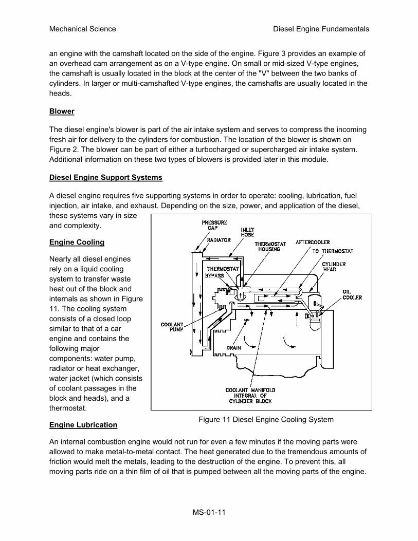
Engine Cooling
Nearly all diesel engines
rely on a liquid cooling
system to transfer waste
heat out of the block and
internals as shown in Figure
11. The cooling system
consists of a closed loop
similar to that of a car
engine and contains the
following major
components: water pump,
radiator or heat exchanger,
water jacket (which consists
of coolant passages in the
block and heads), and a
thermostat.
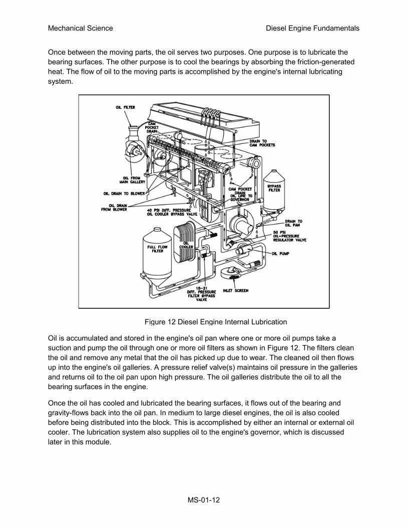
Engine Lubrication
An internal combustion engine would not run for even a few minutes if the moving parts were
allowed to make metal-to-metal contact. The heat generated due to the tremendous amounts of
friction would melt the metals, leading to the destruction of the engine. To prevent this, all
moving parts ride on a thin film of oil that is pumped between all the moving parts of the engine.
Figure 11 Diesel Engine Cooling System
Mechanical Science Diesel Engine Fundamentals
MS-01-12
Figure 12 Diesel Engine Internal Lubrication
System
Once between the moving parts, the oil serves two purposes. One purpose is to lubricate the
bearing surfaces. The other purpose is to cool the bearings by absorbing the friction-generated
heat. The flow of oil to the moving parts is accomplished by the engine's internal lubricating
system.
Oil is accumulated and stored in the engine's oil pan where one or more oil pumps take a
suction and pump the oil through one or more oil filters as shown in Figure 12. The filters clean
the oil and remove any metal that the oil has picked up due to wear. The cleaned oil then flows
up into the engine's oil galleries. A pressure relief valve(s) maintains oil pressure in the galleries
and returns oil to the oil pan upon high pressure. The oil galleries distribute the oil to all the
bearing surfaces in the engine.
Once the oil has cooled and lubricated the bearing surfaces, it flows out of the bearing and
gravity-flows back into the oil pan. In medium to large diesel engines, the oil is also cooled
before being distributed into the block. This is accomplished by either an internal or external oil
cooler. The lubrication system also supplies oil to the engine's governor, which is discussed
later in this module.
Mechanical Science Diesel Engine Fundamentals
MS-01-13
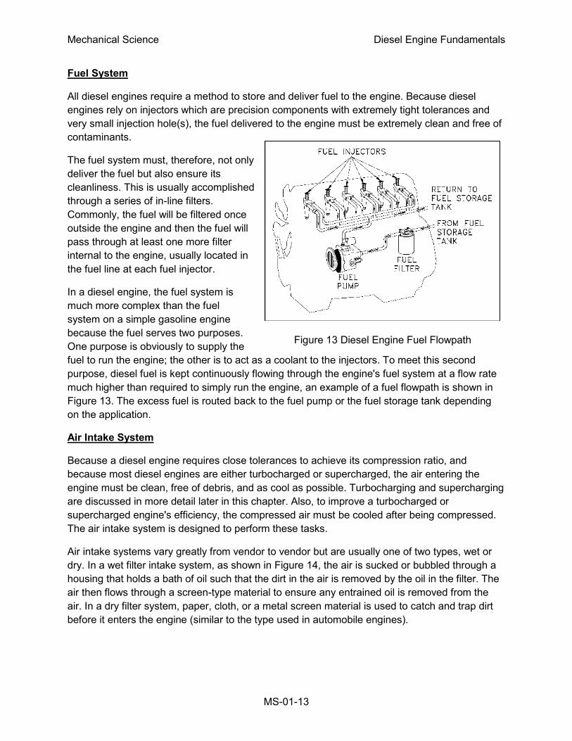
Fuel System
All diesel engines require a method to store and deliver fuel to the engine. Because diesel
engines rely on injectors which are precision components with extremely tight tolerances and
very small injection hole(s), the fuel delivered to the engine must be extremely clean and free of
contaminants.
The fuel system must, therefore, not only
deliver the fuel but also ensure its
cleanliness. This is usually accomplished
through a series of in-line filters.
Commonly, the fuel will be filtered once
outside the engine and then the fuel will
pass through at least one more filter
internal to the engine, usually located in
the fuel line at each fuel injector.
In a diesel engine, the fuel system is
much more complex than the fuel
system on a simple gasoline engine
because the fuel serves two purposes.
One purpose is obviously to supply the
fuel to run the engine; the other is to act as a coolant to the injectors. To meet this second
purpose, diesel fuel is kept continuously flowing through the engine's fuel system at a flow rate
much higher than required to simply run the engine, an example of a fuel flowpath is shown in
Figure 13. The excess fuel is routed back to the fuel pump or the fuel storage tank depending
on the application.
Air Intake System
Because a diesel engine requires close tolerances to achieve its compression ratio, and
because most diesel engines are either turbocharged or supercharged, the air entering the
engine must be clean, free of debris, and as cool as possible. Turbocharging and supercharging
are discussed in more detail later in this chapter. Also, to improve a turbocharged or
supercharged engine's efficiency, the compressed air must be cooled after being compressed.
The air intake system is designed to perform these tasks.
Air intake systems vary greatly from vendor to vendor but are usually one of two types, wet or
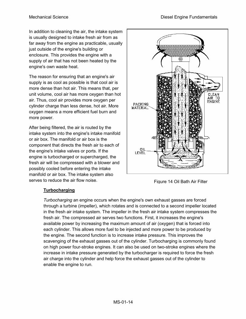
dry. In a wet filter intake system, as shown in Figure 14, the air is sucked or bubbled through a
housing that holds a bath of oil such that the dirt in the air is removed by the oil in the filter. The
air then flows through a screen-type material to ensure any entrained oil is removed from the
air. In a dry filter system, paper, cloth, or a metal screen material is used to catch and trap dirt
before it enters the engine (similar to the type used in automobile engines).
Figure 13 Diesel Engine Fuel Flowpath
Mechanical Science Diesel Engine Fundamentals
MS-01-14
In addition to cleaning the air, the intake system
is usually designed to intake fresh air from as
far away from the engine as practicable, usually
just outside of the engine's building or
enclosure. This provides the engine with a
supply of air that has not been heated by the
engine's own waste heat.
The reason for ensuring that an engine's air
supply is as cool as possible is that cool air is
more dense than hot air. This means that, per
unit volume, cool air has more oxygen than hot
air. Thus, cool air provides more oxygen per
cylinder charge than less dense, hot air. More
oxygen means a more efficient fuel burn and
more power.
After being filtered, the air is routed by the
intake system into the engine's intake manifold
or air box. The manifold or air box is the
component that directs the fresh air to each of
the engine's intake valves or ports. If the
engine is turbocharged or supercharged, the
fresh air will be compressed with a blower and
possibly cooled before entering the intake
manifold or air box. The intake system also
serves to reduce the air flow noise.
Turbocharging
Turbocharging an engine occurs when the engine's own exhaust gasses are forced
through a turbine (impeller), which rotates and is connected to a second impeller located
in the fresh air intake system. The impeller in the fresh air intake system compresses the
fresh air. The compressed air serves two functions. First, it increases the engine's
available power by increasing the maximum amount of air (oxygen) that is forced into
each cylinder. This allows more fuel to be injected and more power to be produced by
the engine. The second function is to increase intake pressure. This improves the
scavenging of the exhaust gasses out of the cylinder. Turbocharging is commonly found
on high power four-stroke engines. It can also be used on two-stroke engines where the
increase in intake pressure generated by the turbocharger is required to force the fresh
air charge into the cylinder and help force the exhaust gasses out of the cylinder to
enable the engine to run.
Figure 14 Oil Bath Air Filter
Mechanical Science Diesel Engine Fundamentals
MS-01-15
Supercharging
Supercharging an engine performs the same function as turbocharging an engine. The
difference is the source of power used to drive the device that compresses the incoming
fresh air. In a supercharged engine, the air is commonly compressed in a device called a
blower. The blower is driven through gears directly from the engines crankshaft. The
most common type of blower uses two rotating rotors to compress the air.
Supercharging is more commonly found on two-stroke engines where the higher
pressures that a supercharger is capable of generating are needed.
Exhaust System
The exhaust system of a diesel engine performs three functions. First, the exhaust system
routes the spent combustion gasses away from the engine, where they are diluted by the
atmosphere. This keeps the area around the engine habitable. Second, the exhaust system
confines and routes the gasses to the turbocharger, if used. Third, the exhaust system allows
mufflers to be used to reduce the engine noise.
Operational Terminology
Before a detailed operation of a diesel engine can be explained, several terms must be defined.
Bore and Stroke
Bore and stroke are terms used to define the size of an engine. As previously stated,
bore refers to the diameter of the engine's cylinder, and stroke refers to the distance the
piston travels from the top of the cylinder to the bottom. The highest point of travel by the
piston is called top dead center (TDC), and the lowest point of travel is called bottom
dead center (BDC). There are 180o of travel between TDC and BDC, or one stroke.
Engine Displacement
Engine displacement is one of the terms used to compare one engine to another.
Displacement refers to the total volume displaced by all the pistons during one stroke.
The displacement is usually given in cubic inches or liters. To calculate the displacement
of an engine, the volume of one cylinder must be determined (volume of a cylinder =
(πr2)h where h = the stroke). The volume of one cylinder is multiplied by the number of
cylinders to obtain the total engine displacement.
Degree of Crankshaft Rotation
All events that occur in an engine are related to the location of the piston. Because the
piston is connected to the crankshaft, any location of the piston corresponds directly to a
specific number of degrees of crankshaft rotation.
Location of the crank can then be stated as XX degrees before or XX degrees after top
or bottom dead center.
Mechanical Science Diesel Engine Fundamentals
MS-01-16
Firing Order
Firing order refers to the order in which each of the cylinders in a multicylinder engine
fires (power stroke). For example, a four cylinder engine's firing order could be 1-4-3-2.
This means that the number 1 cylinder fires, then the number 4 cylinder fires, then the
number 3 cylinder fires, and so on. Engines are designed so that the power strokes are
as uniform as possible, that is, as the crankshaft rotates a certain number of degrees,
one of the cylinders will go through a power stroke. This reduces vibration and allows the
power generated by the engine to be applied to the load in a smoother fashion than if
they were all to fire at once or in odd multiples.
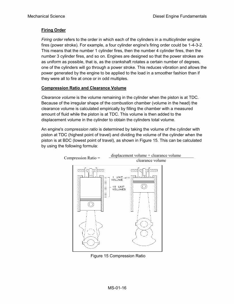
Compression Ratio and Clearance Volume
Clearance volume is the volume remaining in the cylinder when the piston is at TDC.
Because of the irregular shape of the combustion chamber (volume in the head) the
clearance volume is calculated empirically by filling the chamber with a measured
amount of fluid while the piston is at TDC. This volume is then added to the
displacement volume in the cylinder to obtain the cylinders total volume.
An engine's compression ratio is determined by taking the volume of the cylinder with
piston at TDC (highest point of travel) and dividing the volume of the cylinder when the
piston is at BDC (lowest point of travel), as shown in Figure 15. This can be calculated
by using the following formula:
Compression Ratio = displacement volume + clearance volume
clearance volume
Figure 15 Compression Ratio
Mechanical Science Diesel Engine Fundamentals
MS-01-17
Horsepower
Power is the amount of work done per unit time or the rate of doing work. For a diesel
engine, power is rated in units of horsepower. Indicated horsepower is the power
transmitted to the pistons by the gas in the cylinders and is mathematically calculated.
Brake horsepower refers to the amount of usable power delivered by the engine to the
crankshaft. Indicated horsepower can be as much as 15% higher than brake
horsepower. The difference is due to internal engine friction, combustion inefficiencies,
and parasitic losses, for example, oil pump, blower, water pump, etc.
The ratio of an engine's brake horsepower and its indicated horsepower is called the
mechanical efficiency of the engine. The mechanical efficiency of a four-cycle diesel is
about 82 to 90 percent. This is slightly lower than the efficiency of the two-cycle diesel
engine. The lower mechanical efficiency is due to the additional friction losses and
power needed to drive the piston through the extra 2 strokes.
Engines are rated not only in horsepower but also by the torque they produce. Torque is
a measure of the engine's ability to apply the power it is generating. Torque is commonly
given in units of lb-ft.
Summary
The important information in this chapter is summarized below.
Diesel Engines Summary
The compression ratio is the volume of the cylinder with piston at TDC divided by the volume of the cylinder with piston at BDC.
Bore is the diameter of the cylinder.
Stroke is the distance the piston travels from TDC to BDC, and is determined by the eccentricity of the crankshaft.
The combustion chamber is the volume of space where the fuel air mixture is burned in an engine. This is in the cylinder of the engine.
The following components were discussed and identified on a drawing:
a. Piston and rod
b. Cylinder
c. Blower
d. Crankshaft
e. Intake ports or valve(s)
f. Exhaust ports or valve(s)
g. Fuel injector
Mechanical Science Diesel Engine Fundamentals
MS-01-18
FUNDAMENTALS OF THE DIESEL CYCLE
Diesel engines operate under the principle of the internal combustion engine.
There are two basic types of diesel engines, two-cycle and four-cycle. An
understanding of how each cycle operates is required to understand how to
correctly operate and maintain a diesel engine.
EO 1.3 EXPLAIN how a diesel engine converts the chemical energy stored in the
diesel fuel into mechanical energy.
EO 1.4 EXPLAIN how the ignition process occurs in a diesel engine.
EO 1.5 EXPLAIN the operation of a 4-cycle diesel engine, including when the
following events occur during a cycle:
a. Intake
b. Exhaust
c. Fuel injection
d. Compression
e. Power
EO 1.6 EXPLAIN the operation of a 2-cycle diesel engine, including when the
following events occur during a cycle:
a. Intake
b. Exhaust
c. Fuel injection
d. Compression
e. Power
The Basic Diesel Cycles
A diesel engine is a type of heat engine that uses the internal combustion process to convert the
energy stored in the chemical bonds of the fuel into useful mechanical energy. This occurs in
two steps. First, the fuel reacts chemically (burns) and releases energy in the form of heat.
Second the heat causes the gasses trapped in the cylinder to expand, and the expanding
gases, being confined by the cylinder, must move the piston to expand. The reciprocating
motion of the piston is then converted into rotational motion by the crankshaft.
To convert the chemical energy of the fuel into useful mechanical energy all internal combustion
engines must go through four events: intake, compression, power, and exhaust. How these
events are timed and how they occur differentiates the various types of engines.
Mechanical Science Diesel Engine Fundamentals
MS-01-19
Figure 16 Scavenging and
Intake
All diesel engines fall into one of two categories, two-stroke or four-stroke cycle engines. The
word cycle refers to any operation or series of events that repeats itself. In the case of a four-
stroke cycle engine, the engine requires four strokes of the piston (intake, compression, power,
and exhaust) to complete one full cycle. Therefore, it requires two rotations of the crankshaft, or
720° of crankshaft rotation (360° x 2) to complete one cycle. In a two-stroke cycle engine the
events (intake, compression, power, and exhaust) occur in only one rotation of the crankshaft,
or 360°.
Timing
In the following discussion of the diesel cycle it is important to keep in mind the time frame in
which each of the actions is required to occur. Time is required to move exhaust gas out of the
cylinder and fresh air in to the cylinders, to compress the air, to inject fuel, and to burn the fuel.
If a four-stroke diesel engine is running at a constant 2100 revolutions per minute (rpm), the
crankshaft would be rotating at 35 revolutions, or 12,600 degrees, per second. One stroke is
completed in about 0.01429 seconds.
The Four-Stoke Cycle
In a four-stroke engine the camshaft is geared so that it rotates at half the speed of the
crankshaft (1:2). This means that the crankshaft must make two complete revolutions before the
camshaft will complete one revolution. The following section will describe a four-stroke, normally
aspirated, diesel engine having both intake and exhaust valves with a 3.5-inch bore and 4-inch
stroke with a 16:1 compression ratio, as it passes through one complete cycle. We will start on
the intake stroke. All the timing marks given are generic and will
vary from engine to engine. Refer to Figures 10, 16, and 17 during
the following discussion.
Intake
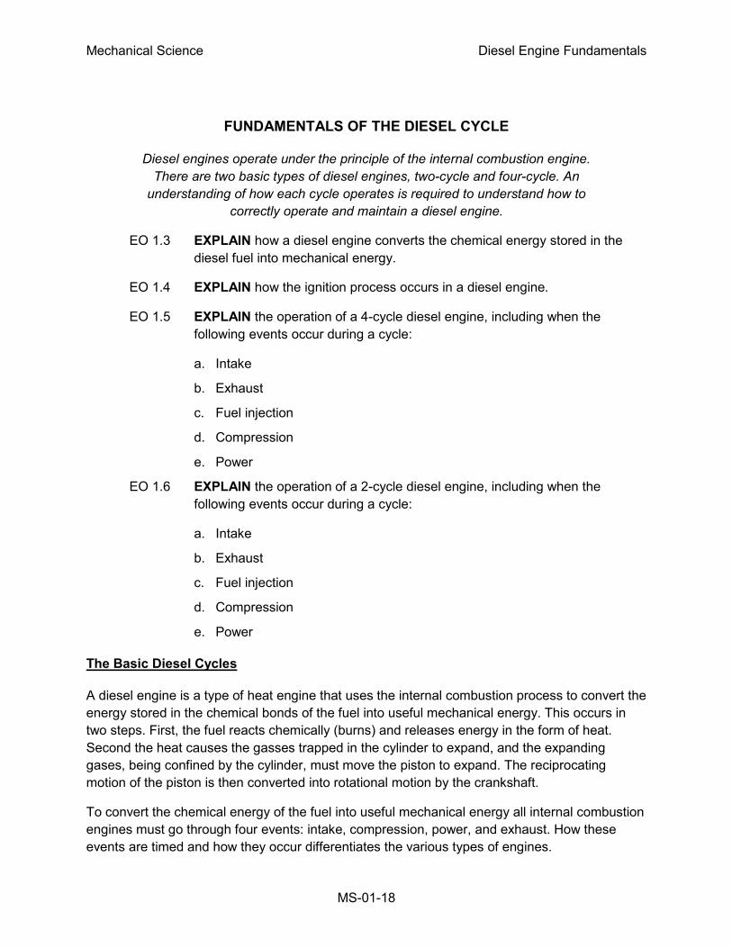
As the piston moves upward and approaches 28° before
top dead center (BTDC), as measured by crankshaft
rotation, the camshaft lobe starts to lift the cam follower.
This causes the pushrod to move upward and pivots the
rocker arm on the rocker arm shaft. As the valve lash is
taken up, the rocker arm pushes the intake valve
downward and the valve starts to open. The intake stroke
now starts while the exhaust valve is still open. The flow of
the exhaust gasses will have created a low pressure
condition within the cylinder and will help pull in the fresh
air charge as shown in Figure 16.
The piston continues its upward travel through top dead
center (TDC) while fresh air enters and exhaust gasses leave. At about 12° after top
dead center (ATDC), the camshaft exhaust lobe rotates so that the exhaust valve will
start to close. The valve is fully closed at 23° ATDC. This is accomplished through the
Mechanical Science Diesel Engine Fundamentals
MS-01-20
valve spring, which was compressed when the valve was opened, forcing the rocker arm
and cam follower back against the cam lobe as it rotates. The time frame during which
both the intake and exhaust valves are open is called valve overlap (51° of overlap in
this example) and is necessary to allow the fresh air to help scavenge (remove) the
spent exhaust gasses and cool the cylinder. In most engines, 30 to 50 times cylinder
volume is scavenged through the cylinder during overlap. This excess cool air also
provides the necessary cooling effect on the engine parts.
As the piston passes TDC and begins to travel down the cylinder bore, the movement of
the piston creates a suction and continues to draw fresh air into the cylinder.
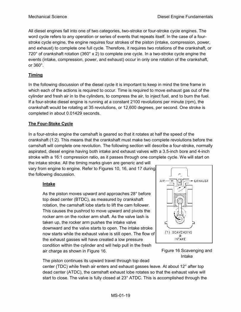
Compression
At 35° after bottom dead center (ABDC), the intake valve
starts to close. At 43° ABDC (or 137° BTDC), the intake
valve is on its seat and is fully closed. At this point the air
charge is at normal pressure (14.7 psia) and ambient air
temperature (~80°F), as illustrated in Figure 17.
At about 70° BTDC, the piston has traveled about 2.125
inches, or about half of its stroke, thus reducing the volume
in the cylinder by half. The temperature has now doubled
to ~160°F and pressure is ~34 psia.
At about 43° BTDC the piston has traveled upward 3.062
inches of its stroke and the volume is once again halved.
Consequently, the temperature again doubles to about
320°F and pressure is ~85 psia. When the piston has
traveled to 3.530 inches of its stroke the volume is again
halved and temperature reaches ~640°F and pressure 277 psia. When the piston has
traveled to 3.757 inches of its stroke, or the volume is again halved, the temperature
climbs to 1280°F and pressure reaches 742 psia. With a piston area of 9.616 in2 the
pressure in the cylinder is exerting a force of approximately
7135 lb. or 3-1/2 tons of force.
The above numbers are ideal and provide a good example
of what is occurring in an engine during compression. In an
actual engine, pressures reach only about 690 psia. This is
due primarily to the heat loss to the surrounding engine
parts.
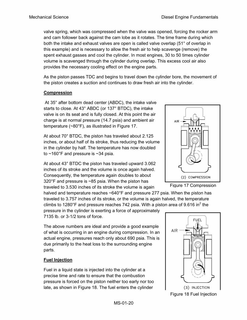
Fuel Injection
Fuel in a liquid state is injected into the cylinder at a
precise time and rate to ensure that the combustion
pressure is forced on the piston neither too early nor too
late, as shown in Figure 18. The fuel enters the cylinder
Figure 17 Compression
Figure 18 Fuel Injection
Mechanical Science Diesel Engine Fundamentals
MS-01-21
where the heated compressed air is present; however, it will only burn when it is in a
vaporized state (attained through the addition of heat to cause vaporization) and
intimately mixed with a supply of oxygen. The first minute droplets of fuel enter the
combustion chamber and are quickly vaporized. The vaporization of the fuel causes the
air surrounding the fuel to cool and it requires time for the air to reheat sufficiently to
ignite the vaporized fuel. But once ignition has started, the additional heat from
combustion helps to further vaporize the new fuel entering the chamber, as long as
oxygen is present. Fuel injection starts at 28° BTDC and ends at 3° ATDC; therefore,
fuel is injected for a duration of 31°.
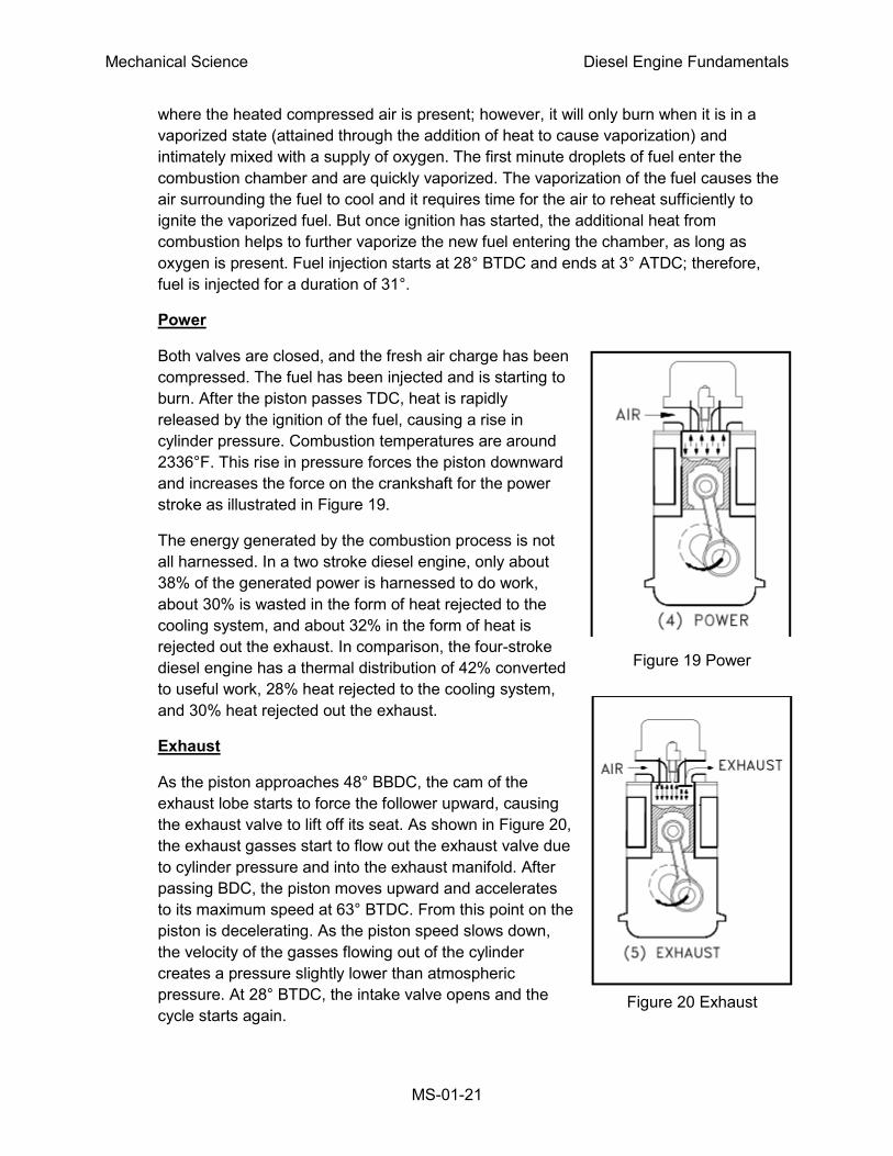
Power
Both valves are closed, and the fresh air charge has been
compressed. The fuel has been injected and is starting to
burn. After the piston passes TDC, heat is rapidly
released by the ignition of the fuel, causing a rise in
cylinder pressure. Combustion temperatures are around
2336°F. This rise in pressure forces the piston downward
and increases the force on the crankshaft for the power
stroke as illustrated in Figure 19.
The energy generated by the combustion process is not
all harnessed. In a two stroke diesel engine, only about
38% of the generated power is harnessed to do work,
about 30% is wasted in the form of heat rejected to the
cooling system, and about 32% in the form of heat is
rejected out the exhaust. In comparison, the four-stroke
diesel engine has a thermal distribution of 42% converted
to useful work, 28% heat rejected to the cooling system,
and 30% heat rejected out the exhaust.
Exhaust
As the piston approaches 48° BBDC, the cam of the
exhaust lobe starts to force the follower upward, causing
the exhaust valve to lift off its seat. As shown in Figure 20,
the exhaust gasses start to flow out the exhaust valve due
to cylinder pressure and into the exhaust manifold. After
passing BDC, the piston moves upward and accelerates
to its maximum speed at 63° BTDC. From this point on the
piston is decelerating. As the piston speed slows down,
the velocity of the gasses flowing out of the cylinder
creates a pressure slightly lower than atmospheric
pressure. At 28° BTDC, the intake valve opens and the
cycle starts again.
Figure 19 Power
Figure 20 Exhaust
Mechanical Science Diesel Engine Fundamentals
MS-01-22
The Two-Stroke Cycle
Like the four-stroke engine, the two-stroke engine must go through through the same four
events: intake, compression, power, and exhaust. But a two-stroke engine requires only two
strokes of the piston to complete one full cycle. Therefore, it requires only one rotation of the
crankshaft to complete a cycle. This means several events must occur during each stroke for all
four events to be completed in two strokes, as opposed to the four-stroke engine where each
stroke basically contains one event.
In a two-stroke engine the camshaft is geared so that it rotates at the same speed as the
crankshaft (1:1). The following section will describe a two-stroke, supercharged, diesel engine
having intake ports and exhaust valves with a 3.5-inch bore and 4-inch stroke with a 16:1
compression ratio, as it passes through one complete cycle. We will start on the exhaust stroke.
All the timing marks given are generic and will vary from engine to engine.
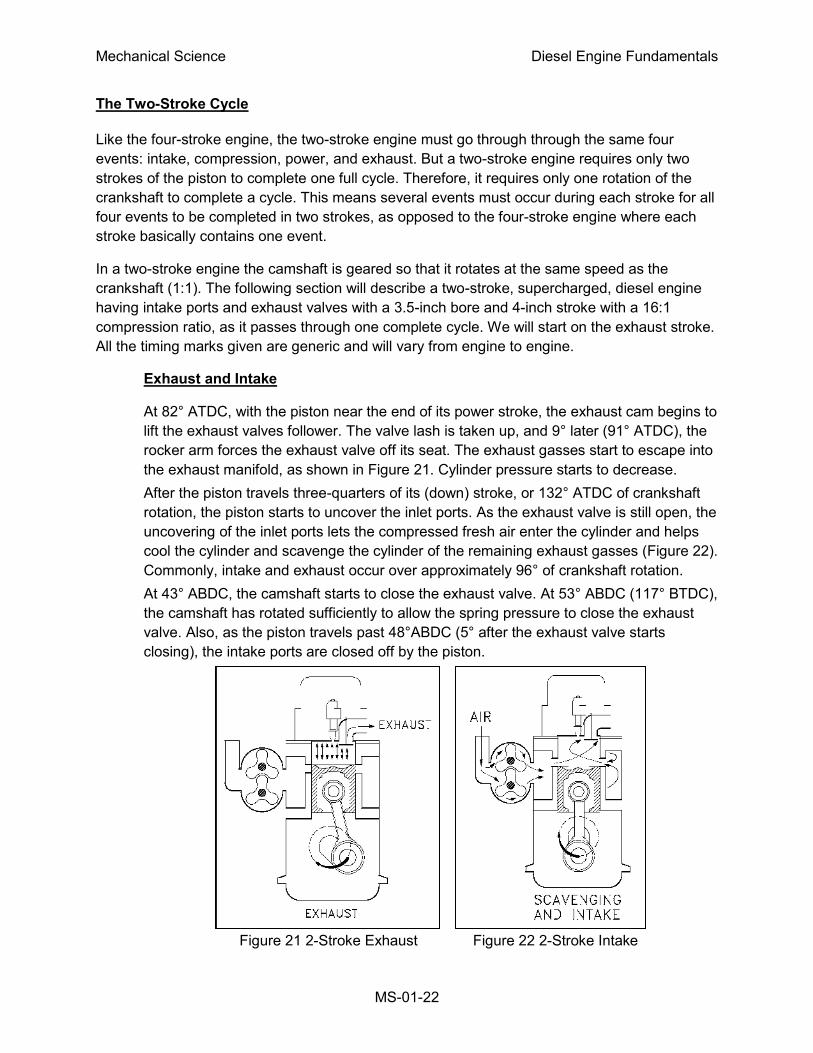
Exhaust and Intake
At 82° ATDC, with the piston near the end of its power stroke, the exhaust cam begins to
lift the exhaust valves follower. The valve lash is taken up, and 9° later (91° ATDC), the
rocker arm forces the exhaust valve off its seat. The exhaust gasses start to escape into
the exhaust manifold, as shown in Figure 21. Cylinder pressure starts to decrease.
After the piston travels three-quarters of its (down) stroke, or 132° ATDC of crankshaft
rotation, the piston starts to uncover the inlet ports. As the exhaust valve is still open, the
uncovering of the inlet ports lets the compressed fresh air enter the cylinder and helps
cool the cylinder and scavenge the cylinder of the remaining exhaust gasses (Figure 22).
Commonly, intake and exhaust occur over approximately 96° of crankshaft rotation.
At 43° ABDC, the camshaft starts to close the exhaust valve. At 53° ABDC (117° BTDC),
the camshaft has rotated sufficiently to allow the spring pressure to close the exhaust
valve. Also, as the piston travels past 48°ABDC (5° after the exhaust valve starts
closing), the intake ports are closed off by the piston.
Figure 21 2-Stroke Exhaust Figure 22 2-Stroke Intake
Mechanical Science Diesel Engine Fundamentals
MS-01-23
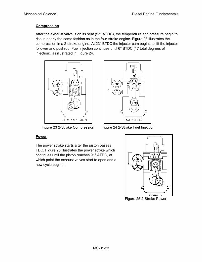
Compression
After the exhaust valve is on its seat (53° ATDC), the temperature and pressure begin to
rise in nearly the same fashion as in the four-stroke engine. Figure 23 illustrates the
compression in a 2-stroke engine. At 23° BTDC the injector cam begins to lift the injector
follower and pushrod. Fuel injection continues until 6° BTDC (17 total degrees of
injection), as illustrated in Figure 24.
Power
The power stroke starts after the piston passes
TDC. Figure 25 illustrates the power stroke which
continues until the piston reaches 91° ATDC, at
which point the exhaust valves start to open and a
new cycle begins.
Figure 25 2-Stroke Power
Figure 23 2-Stroke Compression Figure 24 2-Stroke Fuel Injection
Mechanical Science Diesel Engine Fundamentals
MS-01-24
Summary
The important information in this chapter is summarized below.
Fundamentals of the Diesel Cycle Summary
Ignition occurs in a diesel by injecting fuel into the air charge which has been heated
by compression to a temperature greater than the ignition point of the fuel.
A diesel engine converts the energy stored in the fuel's chemical bonds into
mechanical energy by burning the fuel. The chemical reaction of burning the fuel
liberates heat, which causes the gasses to expand, forcing the piston to rotate the
crankshaft.
A four-stroke engine requires two rotations of the crankshaft to complete one cycle.
The event occur as follows:
Intake - the piston passes TDC, the intake valve(s) open and the fresh air is
admitted into the cylinder, the exhaust valve is still open for a few degrees to
allow scavenging to occur.
Compression - after the piston passes BDC the intake valve closes and the
piston travels up to TDC (completion of the first crankshaft rotation).
Fuel injection - As the piston nears TDC on the compression stroke, the fuel is
injected by the injectors and the fuel starts to burn, further heating the gasses
in the cylinder.
Power - the piston passes TDC and the expanding gasses force the piston
down, rotating the crankshaft.
Exhaust - as the piston passes BDC the exhaust valves open and the exhaust
gasses start to flow out of the cylinder. This continues as the piston travels up
to TDC, pumping the spent gasses out of the cylinder. At TDC the second
crankshaft rotation is complete.
A two-stroke engine requires one rotation of the crankshaft to complete one cycle. The
events occur as follows:
Intake - the piston is near BDC and exhaust is in progress. The intake valve or
ports open and the fresh air is forced in. The exhaust valves or ports are closed
and intake continues.
Mechanical Science Diesel Engine Fundamentals
MS-01-25
Fundamentals of the Diesel Cycle Summary (Cont.)
Compression - after both the exhaust and intake valves or ports are closed, the
piston travels up towards TDC. The fresh air is heated by the compression.
Fuel injection - near TDC the fuel is injected by the injectors and the fuel starts to
burn, further heating the gasses in the cylinder.
Power - the piston passes TDC and the expanding gasses force the piston down,
rotating the crankshaft.
Exhaust - as the piston approaches BDC the exhaust valves or ports open and
the exhaust gasses start to flow out of the cylinder.
Mechanical Science Diesel Engine Fundamentals
MS-01-26
DIESEL ENGINE SPEED, FUEL CONTROLS, AND PROTECTION
Understanding how diesel engines are controlled and the types of protective
instrumentation available is important for a complete understanding of the
operation of a diesel engine.
EO 1.7 DESCRIBE how the mechanical-hydraulic governor on a diesel
engine controls engine speed.
EO 1.8 LIST five protective alarms usually found on mid-sized and larger
diesel engines.
Engine Control
The control of a diesel engine is accomplished through several components: the camshaft, the
fuel injector, and the governor. The camshaft provides the timing needed to properly inject the
fuel, the fuel injector provides the component that meters and injects the fuel, and the governor
regulates the amount of fuel that the injector is to inject. Together, these three major
components ensure that the engine runs at the desired speed.
Fuel Injectors
Each cylinder has a fuel injector designed to meter and inject fuel into the cylinder at the proper
instant. To accomplish this function, the injectors are actuated by the engine's camshaft. The
camshaft provides the timing and pumping action used by the injector to inject the fuel. The
injectors meter the amount of fuel injected into the cylinder on each stroke. The amount of fuel
to be injected by each injector is set by a mechanical linkage called the fuel rack. The fuel rack
position is controlled by the engine's governor. The governor determines the amount of fuel
required to maintain the desired engine speed and adjusts the amount to be injected by
adjusting the position of the fuel rack.
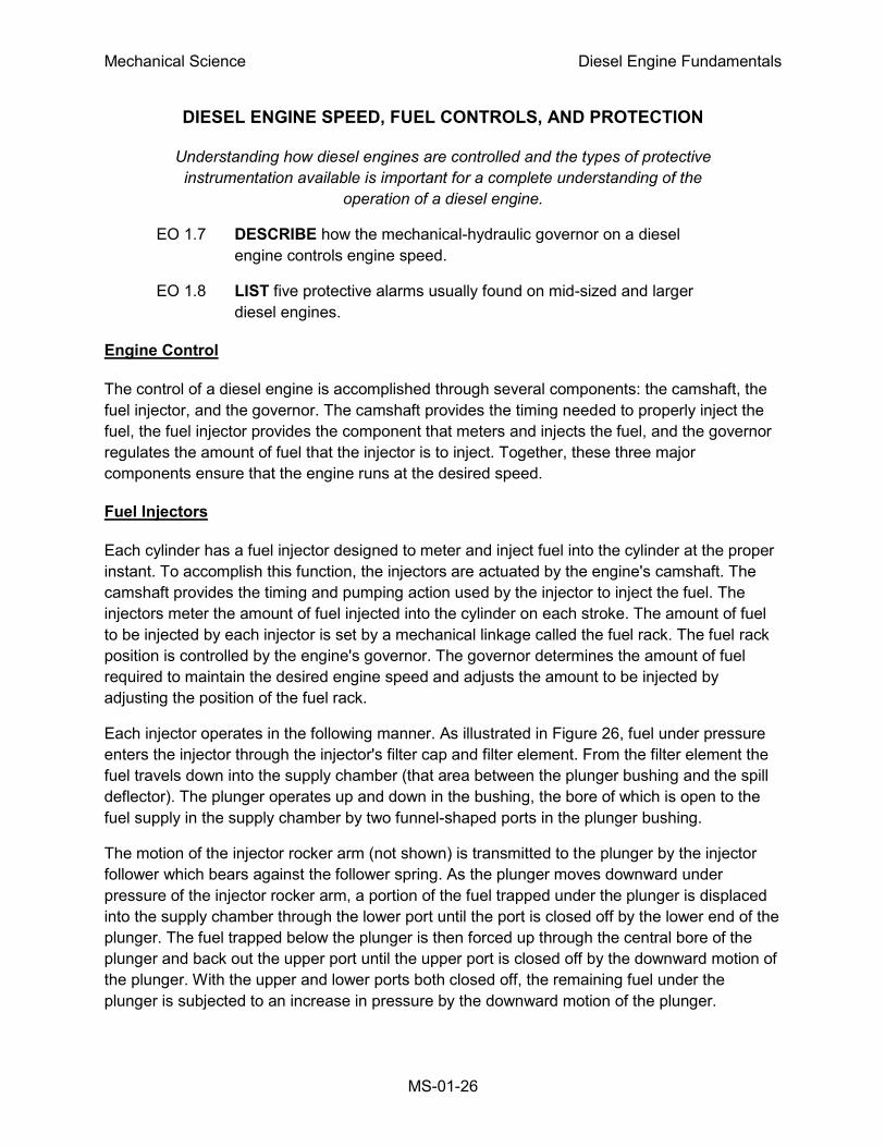
Each injector operates in the following manner. As illustrated in Figure 26, fuel under pressure
enters the injector through the injector's filter cap and filter element. From the filter element the
fuel travels down into the supply chamber (that area between the plunger bushing and the spill
deflector). The plunger operates up and down in the bushing, the bore of which is open to the
fuel supply in the supply chamber by two funnel-shaped ports in the plunger bushing.
The motion of the injector rocker arm (not shown) is transmitted to the plunger by the injector
follower which bears against the follower spring. As the plunger moves downward under
pressure of the injector rocker arm, a portion of the fuel trapped under the plunger is displaced
into the supply chamber through the lower port until the port is closed off by the lower end of the
plunger. The fuel trapped below the plunger is then forced up through the central bore of the
plunger and back out the upper port until the upper port is closed off by the downward motion of
the plunger. With the upper and lower ports both closed off, the remaining fuel under the
plunger is subjected to an increase in pressure by the downward motion of the plunger.
Mechanical Science Diesel Engine Fundamentals
MS-01-27
Figure 26 Fuel Injector Cutaway
Mechanical Science Diesel Engine Fundamentals
MS-01-28
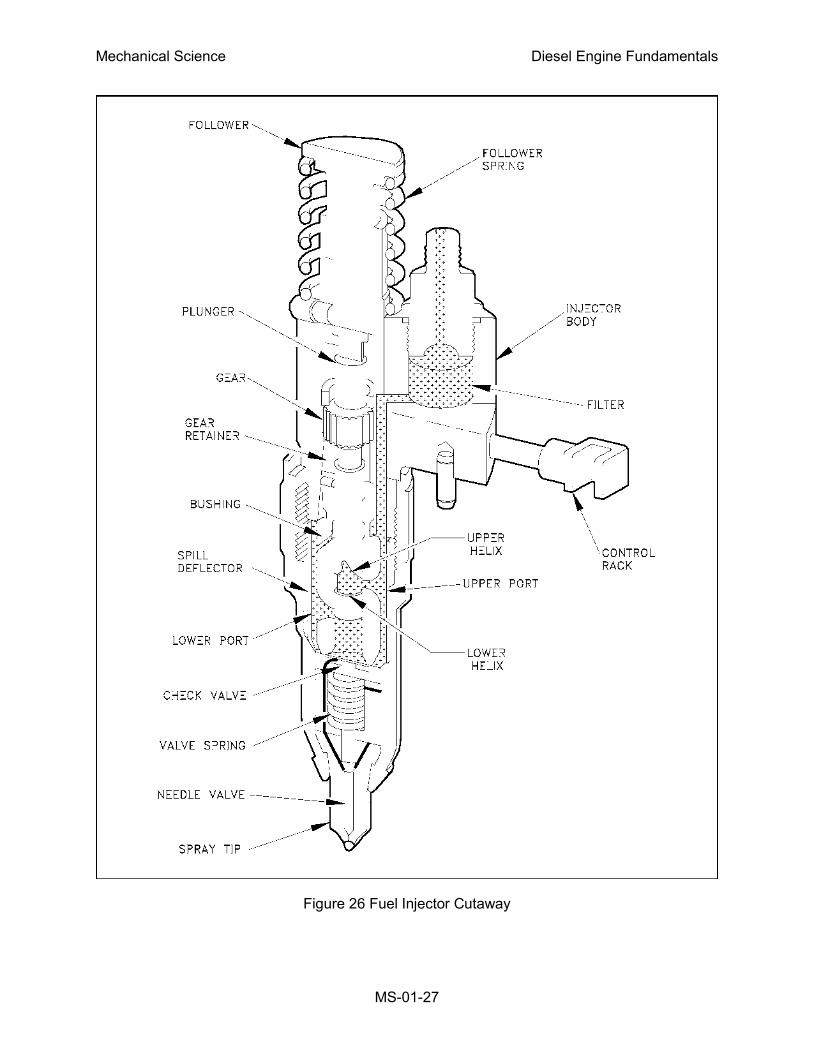
When sufficient pressure has built up, the injector valve is lifted off its seat and the fuel is forced
through small orifices in the spray tip and atomized into the combustion chamber. A check
valve, mounted in the spray tip, prevents air in the combustion chamber from flowing back into
the fuel injector. The plunger is then returned back to its original position by the injector follower
spring.
On the return upward movement of the plunger, the high pressure cylinder within the bushing is
again filled with fresh fuel oil through the ports. The constant circulation of fresh, cool fuel
Figure 27 Fuel Injector Plunger
Mechanical Science Diesel Engine Fundamentals
MS-01-29
through the injector renews the fuel supply in the chamber and helps cool the injector. The fuel
flow also effectively removes all traces of air that might otherwise accumulate in the system.
The fuel injector outlet opening, through which the excess fuel returns to the fuel return manifold
and then back to the fuel tank, is adjacent to the inlet opening and contains a filter element
exactly the same as the one on the fuel inlet side.
In addition to the reciprocating motion of the plunger, the plunger can be rotated during
operation around its axis by the gear which meshes with the fuel rack. For metering the fuel, an
upper helix and a lower helix are machined in the lower part of the plunger. The relation of the
helices to the two ports in the injector bushing changes with the rotation of the plunger.
Changing the position of the helices, by rotating the plunger, retards or advances the closing of
the ports and the beginning and ending of the injection period. At the same time, it increases or
decreases the amount of fuel injected into the cylinder. Figure 27 illustrates the various plunger
positions from NO LOAD to FULL LOAD. With the control rack pulled all the way (no injection),
the upper port is not closed by the helix until after the lower port is uncovered. Consequently,
with the rack in this position, all of the fuel is forced back into the supply chamber and no
injection of fuel takes place. With the control rack pushed all the way in (full injection), the upper
port is closed shortly after the lower port has been covered, thus producing a maximum effective
stroke and maximum fuel injection. From this no-injection position to the full-injection position
(full rack movement), the contour of the upper helix advances the closing of the ports and the
beginning of injection.
Governor
Diesel engine speed is controlled solely by the amount of fuel injected into the engine by the
injectors. Because a diesel engine is not self-speed-limiting, it requires not only a means of
changing engine speed (throttle control) but also a means of maintaining the desired speed. The
governor provides the engine with the feedback mechanism to change speed as needed and to
maintain a speed once reached.
A governor is essentially a speed-sensitive device, designed to maintain a constant engine
speed regardless of load variation. Since all governors used on diesel engines control engine
speed through the regulation of the quantity of fuel delivered to the cylinders, these governors
may be classified as speed-regulating governors. As with the engines themselves there are
many types and variations of governors. In this module, only the common mechanical-hydraulic
type governor will be reviewed.
The major function of the governor is determined by the application of the engine. In an engine
that is required to come up and run at only a single speed regardless of load, the governor is
called a constant-speed type governor. If the engine is manually controlled, or controlled by an
outside device with engine speed being controlled over a range, the governor is called a
variable-speed type governor. If the engine governor is designed to keep the engine speed
above a minimum and below a maximum, then the governor is a speed-limiting type. The last
category of governor is the load limiting type. This type of governor limits fuel to ensure that the
Mechanical Science Diesel Engine Fundamentals
MS-01-30
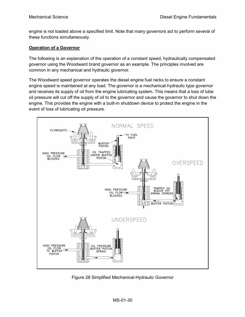
engine is not loaded above a specified limit. Note that many governors act to perform several of
these functions simultaneously.
Operation of a Governor
The following is an explanation of the operation of a constant speed, hydraulically compensated
governor using the Woodward brand governor as an example. The principles involved are
common in any mechanical and hydraulic governor.
The Woodward speed governor operates the diesel engine fuel racks to ensure a constant
engine speed is maintained at any load. The governor is a mechanical-hydraulic type governor
and receives its supply of oil from the engine lubricating system. This means that a loss of lube
oil pressure will cut off the supply of oil to the governor and cause the governor to shut down the
engine. This provides the engine with a built-in shutdown device to protect the engine in the
event of loss of lubricating oil pressure.
Figure 28 Simplified Mechanical-Hydraulic Governor
Mechanical Science Diesel Engine Fundamentals
MS-01-31
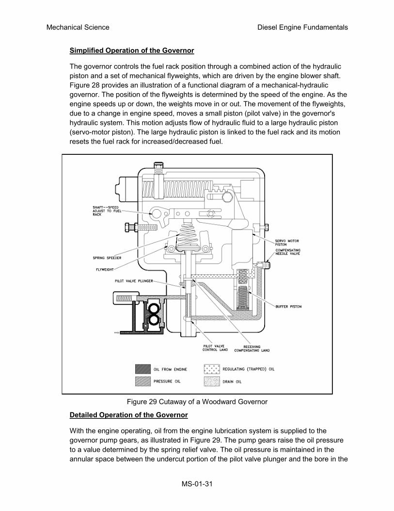
Simplified Operation of the Governor
The governor controls the fuel rack position through a combined action of the hydraulic
piston and a set of mechanical flyweights, which are driven by the engine blower shaft.
Figure 28 provides an illustration of a functional diagram of a mechanical-hydraulic
governor. The position of the flyweights is determined by the speed of the engine. As the
engine speeds up or down, the weights move in or out. The movement of the flyweights,
due to a change in engine speed, moves a small piston (pilot valve) in the governor's
hydraulic system. This motion adjusts flow of hydraulic fluid to a large hydraulic piston
(servo-motor piston). The large hydraulic piston is linked to the fuel rack and its motion
resets the fuel rack for increased/decreased fuel.
Figure 29 Cutaway of a Woodward Governor
Detailed Operation of the Governor
With the engine operating, oil from the engine lubrication system is supplied to the
governor pump gears, as illustrated in Figure 29. The pump gears raise the oil pressure
to a value determined by the spring relief valve. The oil pressure is maintained in the
annular space between the undercut portion of the pilot valve plunger and the bore in the
Mechanical Science Diesel Engine Fundamentals
MS-01-32
pilot valve bushing. For any given speed setting, the spring speeder exerts a force that is
opposed by the centrifugal force of the revolving flyweights. When the two forces are
equal, the control land on the pilot valve plunger covers the lower ports in the pilot valve
bushing.
Under these conditions, equal oil pressures are maintained on both sides of the buffer
piston and tension on the two buffer springs is equal. Also, the oil pressure is equal on
both sides of the receiving compensating land of the pilot valve plunger due to oil
passing through the compensating needle valve. Thus, the hydraulic system is in
balance, and the engine speed remains constant.
When the engine load increases, the engine starts to slow down in speed. The reduction
in engine speed will be sensed by the governor flyweights. The flyweights are forced
inward (by the spring), thus lowering the pilot valve plunger (again, due to the downward
spring force). Oil under pressure will be admitted under the servo-motor piston (topside
of the buffer piston) causing it to rise. This upward motion of the servo-motor piston will
be transmitted through the terminal lever to the fuel racks, thus increasing the amount of
fuel injected into the engine. The oil that forces the servo-motor piston upward also
forces the buffer piston upward because the oil pressure on each side of the piston is
unequal. This upward motion of the piston compresses the upper buffer spring and
relieves the pressure on the lower buffer spring.
The oil cavities above and below the buffer piston are common to the receiving
compensating land on the pilot valve plunger. Because the higher pressure is below the
compensating land, the pilot valve plunger is forced upward, recentering the flyweights
and causing the control land of the pilot valve to close off the regulating port. Thus, the
upward movement of the servo-motor piston stops when it has moved far enough to
make the necessary fuel correction.
Oil passing through the compensating needle valve slowly equalizes the pressures
above and below the buffer piston, thus allowing the buffer piston to return to the center
position, which in turn equalizes the pressure above and below the receiving
compensating land. The pilot valve plunger then moves to its central position and the
engine speed returns to its original setting because there is no longer any excessive
outward force on the flyweights.
The action of the flyweights and the hydraulic feedback mechanism produces stable
engine operation by permitting the governor to move instantaneously in response to the
load change and to make the necessary fuel adjustment to maintain the initial engine
speed.
Starting Circuits
Diesel engines have as many different types of starting circuits as there are types, sizes, and
manufacturers of diesel engines. Commonly, they can be started by air motors, electric motors,
hydraulic motors, and manually. The start circuit can be a simple manual start pushbutton, or a
Mechanical Science Diesel Engine Fundamentals
MS-01-33
complex auto-start circuit. But in almost all cases the following events must occur for the starting
engine to start.
1. The start signal is sent to the starting motor. The air, electric, or hydraulic motor,
will engage the engine's flywheel.
2. The starting motor will crank the engine. The starting motor will spin the engine at
a high enough rpm to allow the engine's compression to ignite the fuel and start
the engine running.
3. The engine will then accelerate to idle speed. When the starter motor is
overdriven by the running motor it will disengage the flywheel.
Because a diesel engine relies on compression heat to ignite the fuel, a cold engine can rob
enough heat from the gasses that the compressed air falls below the ignition temperature of the
fuel. To help overcome this condition, some engines (usually small to medium sized engines)
have glowplugs. Glowplugs are located in the cylinder head of the combustion chamber and use
electricity to heat up the electrode at the top of the glowplug. The heat added by the glowplug is
sufficient to help ignite the fuel in the cold engine. Once the engine is running, the glowplugs are
turned off and the heat of combustion is sufficient to heat the block and keep the engine
running.
Larger engines usually heat the block and/or have powerful starting motors that are able to spin
the engine long enough to allow the compression heat to fire the engine. Some large engines
use air start manifolds that inject compressed air into the cylinders which rotates the engine
during the start sequence.
Engine Protection
A diesel engine is designed with protection systems to alert the operators of abnormal
conditions and to prevent the engine from destroying itself.
Overspeed device - Because a diesel is not self-speed-limiting, a failure in the governor,
injection system, or sudden loss of load could cause the diesel to
overspeed. An overspeed condition is extremely dangerous because
engine failure is usually catastrophic and can possibly cause the engine
to fly apart.
An overspeed device, usually some type of mechanical flyweight, will act
to cut off fuel to the engine and alarm at a certain preset rpm. This is
usually accomplished by isolating the governor from its oil supply, causing
it to travel to the no-fuel position, or it can override the governor and
directly trip the fuel rack to the no-fuel position.
Water jacket - Water-cooled engines can overheat if the cooling water system fails to
remove waste heat. Removal of the waste heat prevents the engine from
seizing due to excessive expansion of the components under a high
Mechanical Science Diesel Engine Fundamentals
MS-01-34
temperature condition. The cooling water jacket is commonly where the
sensor for the cooling water system is located.
The water jacket temperature sensors provide early warning of abnormal
engine temperature, usually an alarm function only. The setpoint is set
such that if the condition is corrected in a timely manner, significant
engine damage will be avoided. But continued engine operation at the
alarm temperature or higher temperatures will lead to engine damage.
Exhaust In a diesel engine, exhaust temperatures are very important and can
temperatures - provide a vast amount of information regarding the
operation of the engine. High exhaust temperature can indicate an
overloading of the engine or possible poor performance due to
inadequate scavenging (the cooling effect) in the engine. Extended
operation with high exhaust temperatures can result in damage to the
exhaust valves, piston, and cylinders. The exhaust temperature usually
provides only an alarm function.
Low lube oil Low oil pressure or loss of oil pressure can destroy an engine in short
pressure - order. Therefore, most medium to larger engines will stop upon low or
loss of oil pressure. Loss of oil pressure can result in the engine seizing
due to lack of lubrication. Engines with mechanical-hydraulic governors
will also stop due to the lack of oil to the governor.
The oil pressure sensor usually stops the engine. The oil pressure
sensors on larger engines usually have two low pressure setpoints. One
setpoint provides early warning of abnormal oil pressure, an alarm
function only. The second setpoint can be set to shutdown the engine
before permanent damage is done.
High crankcase High crankcase pressure is usually caused by excessive blow-by (gas
pressure - pressure in the cylinder blowing by the piston rings and into the
crankcase). The high pressure condition indicates the engine is in poor
condition. The high crankcase pressure is usually used only as an alarm
function.
Mechanical Science Diesel Engine Fundamentals
MS-01-35
Summary
The important information in this chapter is summarized below.
Diesel Engine Speed, Fuel Controls, and Protection Summary
A mechanical-hydraulic governor controls engine speed by balancing
engine speed (mechanical flyweights) against hydraulic pressure. As the
engine speeds up or slows down, the weights move the hydraulic plunger
in or out. This in turn actuates a hydraulic valve which controls the
hydraulic pressure to the buffer piston. The buffer piston is connected to
the fuel rack. Therefore, any motion of the buffer piston will control fuel to
the cylinder by adjusting the position of the fuel rack, which regulates the
amount of fuel in the injectors.
Most mid-sized to large diesel engines have (as a minimum) the following
protective alarms and trips.
Engine overspeed alarm/trip
High water jacket temperature alarm
High exhaust temperature alarm
Low lube oil pressure (alarm and/or trip)
High crankcase pressure alarm