Embed Size (px)
Citation preview
Diesel Engine Combustion
1. Characteristics of diesel combustion
2. Different diesel combustion systems
3. Phenomenological model of diesel combustion process
4. Movie of combustion in diesel systems
5. Combustion pictures and planar laser sheet imaging
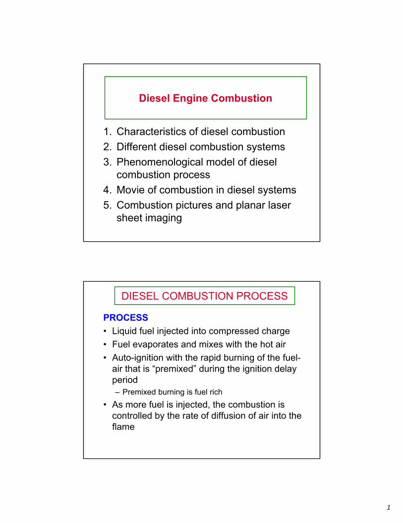
DIESEL COMBUSTION PROCESS
PROCESS
• Liquid fuel injected into compressed charge
• Fuel evaporates and mixes with the hot air • Auto-ignition with the rapid burning of the fuel-
air that is “premixed” during the ignition delay period – Premixed burning is fuel rich
• As more fuel is injected, the combustion is controlled by the rate of diffusion of air into the flame
1
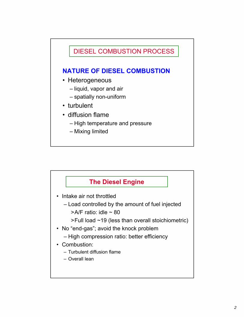
DIESEL COMBUSTION PROCESS
NATURE OF DIESEL COMBUSTION
• Heterogeneous – liquid, vapor and air – spatially non-uniform
• turbulent • diffusion flame
– High temperature and pressure
– Mixing limited
The Diesel Engine
• Intake air not throttled
– Load controlled by the amount of fuel injected
>A/F ratio: idle ~ 80
>Full load ~19 (less than overall stoichiometric) • No “end-gas”; avoid the knock problem
– High compression ratio: better efficiency
• Combustion: – Turbulent diffusion flame
– Overall lean
2
Diesel as the Most Efficient Power Plant
• Theoretically, for the same CR, SI engine has higher f; but diesel is not limited by knock, therefore it can operate at higher CR and achieves higher f
• Not throttled - small pumping loss
• Overall lean - higher value of - higher thermodynamic efficiency
• Can operate at low rpm - applicable to very large engines
– slow speed, plenty of time for combustion
– small surface to volume ratio: lower percentage of parasitic losses (heat transfer and friction)
• Opted for turbo-charging: higher energy density – Reduced parasitic losses (friction and heat transfer) relative to output
Large Diesels: f~ 55% ~ 98% ideal efficiency !
Diesel Engine Characteristics (compared to SI engines)
• Better fuel economy – Overall lean, thermodynamically efficient – Large displacement, low speed – lower FMEP
– Higher CR
> CR limited by peak pressure, NOx emissions, combustion and heat transfer loss
– Turbo-charging not limited by knock: higher BMEP over domain of operation, lower relative losses (friction and heat transfer)
• Lower Power density – Overall lean: would lead to smaller BMEP
– Turbocharged: would lead to higher BMEP
> not knock limited, but NOx limited
> BMEP higher than naturally aspirated SI engine
– Lower speed: overall power density (P/VD) not as high as SI engines
• Emissions: more problematic than SI engine – NOx: needs development of efficient catalyst – PM: regenerative and continuous traps
3
Typical SI and Diesel operating value comparisons
SI Diesel
• BMEP
– Naturally aspirated: 10-15 bar 10 bar – Turbo: 15-25 bar 15-25 bar
• Power density
– Naturally aspirated: 50-70 KW/L 20 KW/L
– Turbo: 70-120 KW/L 40-70 KW/L
• Fuel
– H to C ratio CH1.87 CH1.80
– Stoichiometric A/F 14.6 14.5
– Density 0.75 g/cc 0.81 g/cc
– LHV (mass basis) 44 MJ/kg 43 MJ/kg
– LHV (volume basis) 3.30 MJ/L 3.48 MJ/L (5.5% higher)
– LHV (CO2 basis) 13.9 MJ/kgCO2 13.6 MJ/kgCO2 (2.2% lower)
Disadvantages of Diesel Engines
• Cold start difficulty
• Noisy - sharp pressure rise: cracking noise
• Inherently slower combustion
• Lower power to weight ratio
• Expensive components
• NOx and particulate matters emissions
4
Market penetration
• Diesel driving fuel economy ~ 30% better than SI 5% from fuel energy/volume
15% from eliminating throttle loss
10% from thermodynamics
2nd law losses (friction and heat transfer) Higher compression ratio
Higher specific heat ratio
Dominant world wide heavy duty applications Dominant military applications Significant market share in Europe
Tax structure for fuel and vehicle
Small passenger car market fraction in US and Japan Fuel cost Customer preference Emissions requirement
Applications
• Small (7.5 to 10 cm bore; previously mainly IDI; new ones are high speed DI) – passenger cars
• Medium (10 to 20 cm bore; DI) – trucks, trains
• Large (30 to 50 cm bore; DI) – trains, ships
• Very Large (100 cm bore) – stationary power plants, ships
5
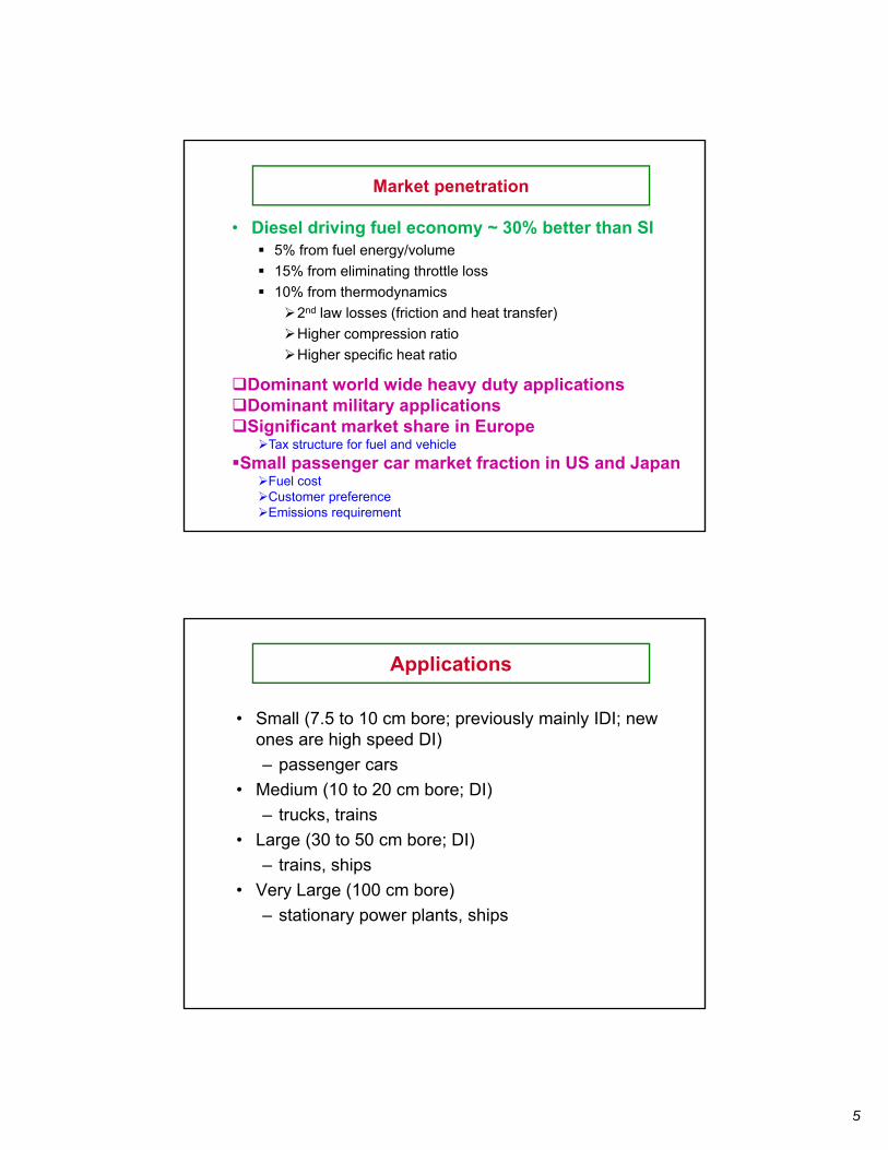
Common Direct-Injection Compression-Ignition Engines(Fig. 10.1 of text)
(a) (c) (b)
(a) Quiescent chamber with multihole nozzle typical of larger engines (b) Bowl-in-piston chamber with swirl and multihole nozzle; medium to small size engines (c) Bowl-in-piston chamber with swirl and single-hole nozzle; medium to small size engines
© McGraw-Hill Education. All rights reserved. This content is excluded from our Creative Commons license. For more information, see https://ocw.mit.edu/help/faq-fair-use.
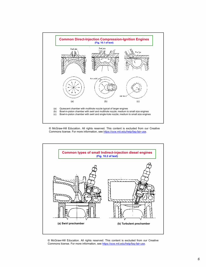
Common types of small Indirect-injection diesel engines (Fig. 10.2 of text)
(a) Swirl prechamber (b) Turbulent prechamber
© McGraw-Hill Education. All rights reserved. This content is excluded from our Creative Commons license. For more information, see https://ocw.mit.edu/help/faq-fair-use.
6
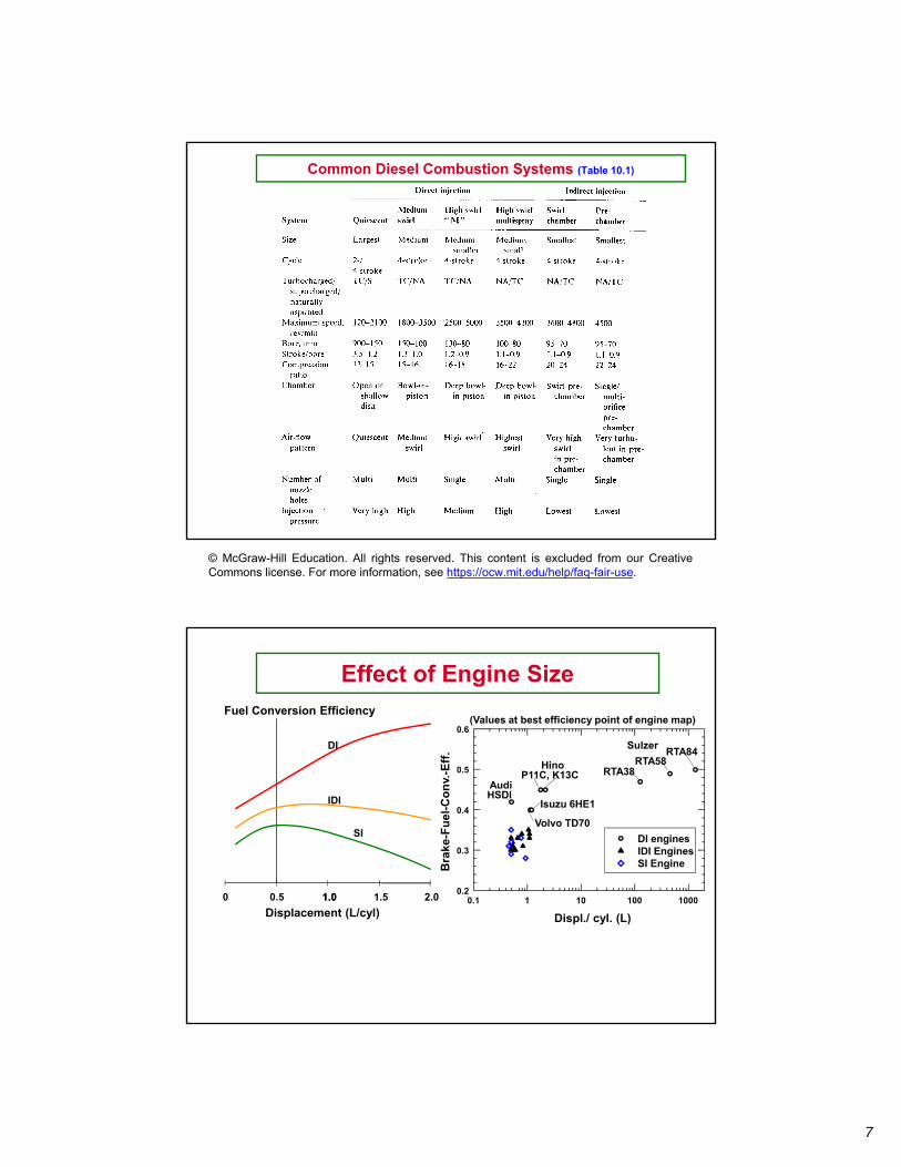
Common Diesel Combustion Systems (Table 10.1)
© McGraw-Hill Education. All rights reserved. This content is excluded from our Creative Commons license. For more information, see https://ocw.mit.edu/help/faq-fair-use.
Effect of Engine Size
2.0
(Values at best efficiency point of engine map)
Displ./ cyl. (L)
0.1 1 10 100 1000
Bra
ke-F
uel
-Co
nv.
-Eff
.
0.2
0.3
0.4
0.5
0.6
DI engines IDI Engines SI Engine
Sulzer
RTA38 RTA58
RTA84 Hino
P11C, K13CAudi HSDI
Volvo TD70
Isuzu 6HE1
0 1.0 1.5
Fuel Conversion Efficiency
Displacement (L/cyl)
DI
IDI
SI
0.5 1.0
7
350
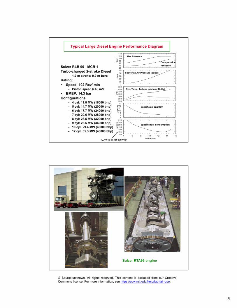
Typical Large Diesel Engine Performance Diagram
Sulzer RLB 90 - MCR 1 Turbo-charged 2-stroke Diesel
– 1.9 m stroke; 0.9 m bore
Rating: • Speed: 102 Rev/ min
– Piston speed 6.46 m/s
• BMEP: 14.3 bar Configurations
– 4 cyl: 11.8 MW (16000 bhp) – 5 cyl: 14.7 MW (20000 bhp) – 6 cyl: 17.7 MW (24000 bhp) – 7 cyl: 20.6 MW (28000 bhp) – 8 cyl: 23.5 MW (32000 bhp) – 9 cyl: 26.5 MW (36000 bhp) – 10 cyl: 29.4 MW (40000 bhp) – 12 cyl: 35.3 MW (48000 bhp)
Max Pressure
Scavenge Air Pressure (gauge)
Exh. Temp, Turbine Inlet and Outlet
Specific air quantity
4 6 8 10 12 14 16
20 40 60 80
100 120 140
(bar
)
0 0.5 1.0 1.5 2.0 2.5
(bar
)
200 250 300
400 450 500
( o C
) 7 8 9
10 11 12 13
(kg/
kWh)
180 185 190 195 200 205 210
(g/k
Wh)
Specific fuel consumption
BMEP (bar)
Compression Pressure
f,b=0.45 @ 185 g/kW-hr
Sulzer RTA96 engine
© Source unknown. All rights reserved. This content is excluded from our Creative Commons license. For more information, see https://ocw.mit.edu/help/faq-fair-use.
8
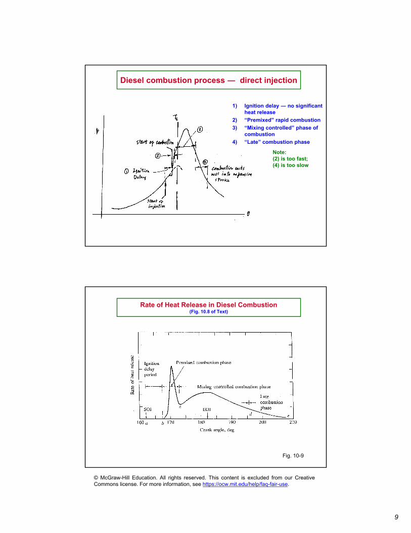
Diesel combustion process ― direct injection
1) Ignition delay ― no significant heat release
2) “Premixed” rapid combustion
3) “Mixing controlled” phase of combustion
4) “Late” combustion phase
Note: (2) is too fast; (4) is too slow
Rate of Heat Release in Diesel Combustion (Fig. 10.8 of Text)
Fig. 10-9
© McGraw-Hill Education. All rights reserved. This content is excluded from our Creative Commons license. For more information, see https://ocw.mit.edu/help/faq-fair-use.
9
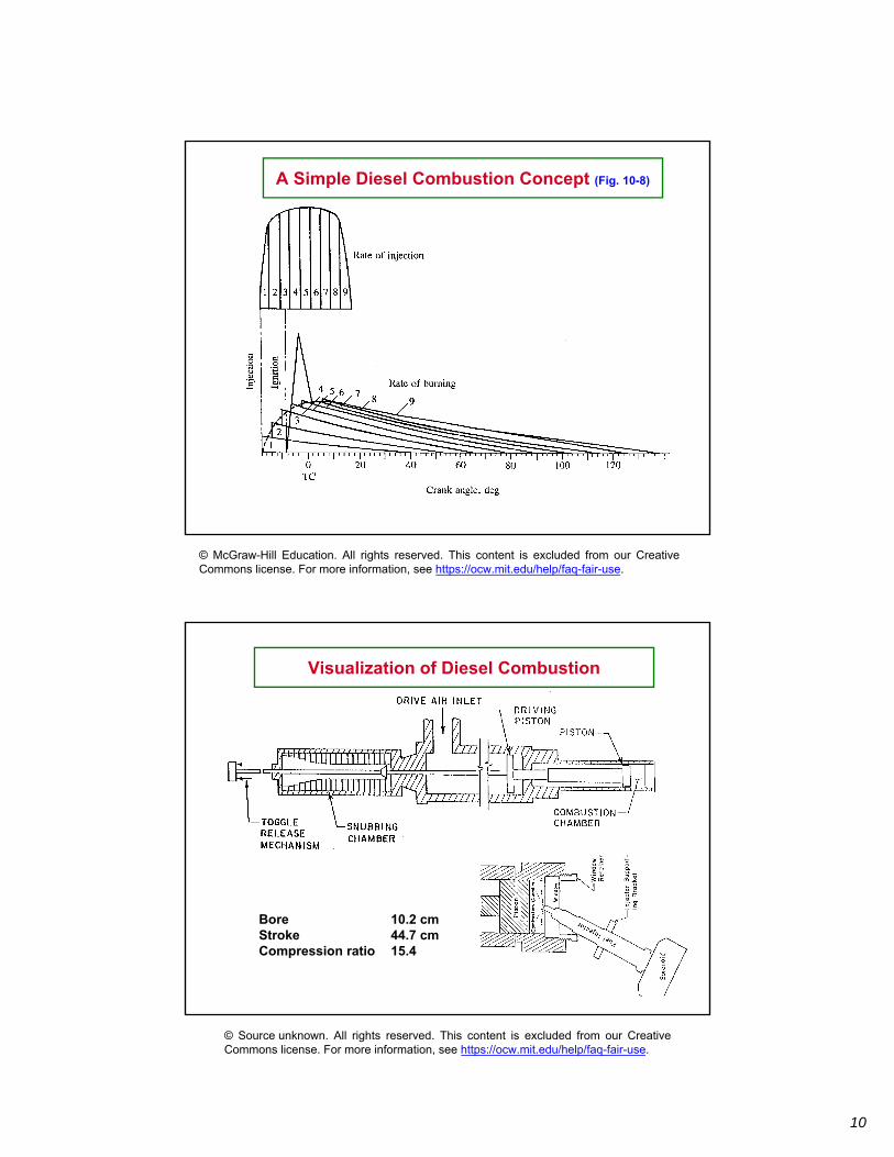
A Simple Diesel Combustion Concept (Fig. 10-8)
© McGraw-Hill Education. All rights reserved. This content is excluded from our Creative Commons license. For more information, see https://ocw.mit.edu/help/faq-fair-use.
Visualization of Diesel Combustion
Bore 10.2 cm Stroke 44.7 cm Compression ratio 15.4
© Source unknown. All rights reserved. This content is excluded from our Creative Commons license. For more information, see https://ocw.mit.edu/help/faq-fair-use.
10
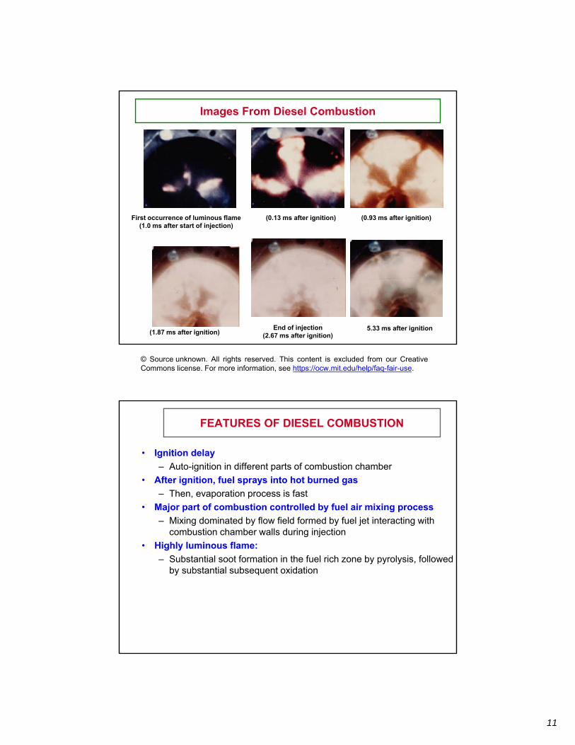
Images From Diesel Combustion
First occurrence of luminous flame (1.0 ms after start of injection)
(0.13 ms after ignition) (0.93 ms after ignition)
5.33 ms after ignition End of injection (1.87 ms after ignition) (2.67 ms after ignition)
© Source unknown. All rights reserved. This content is excluded from our Creative Commons license. For more information, see https://ocw.mit.edu/help/faq-fair-use.
FEATURES OF DIESEL COMBUSTION
• Ignition delay
– Auto-ignition in different parts of combustion chamber • After ignition, fuel sprays into hot burned gas
– Then, evaporation process is fast • Major part of combustion controlled by fuel air mixing process
– Mixing dominated by flow field formed by fuel jet interacting with combustion chamber walls during injection
• Highly luminous flame:
– Substantial soot formation in the fuel rich zone by pyrolysis, followed by substantial subsequent oxidation
11
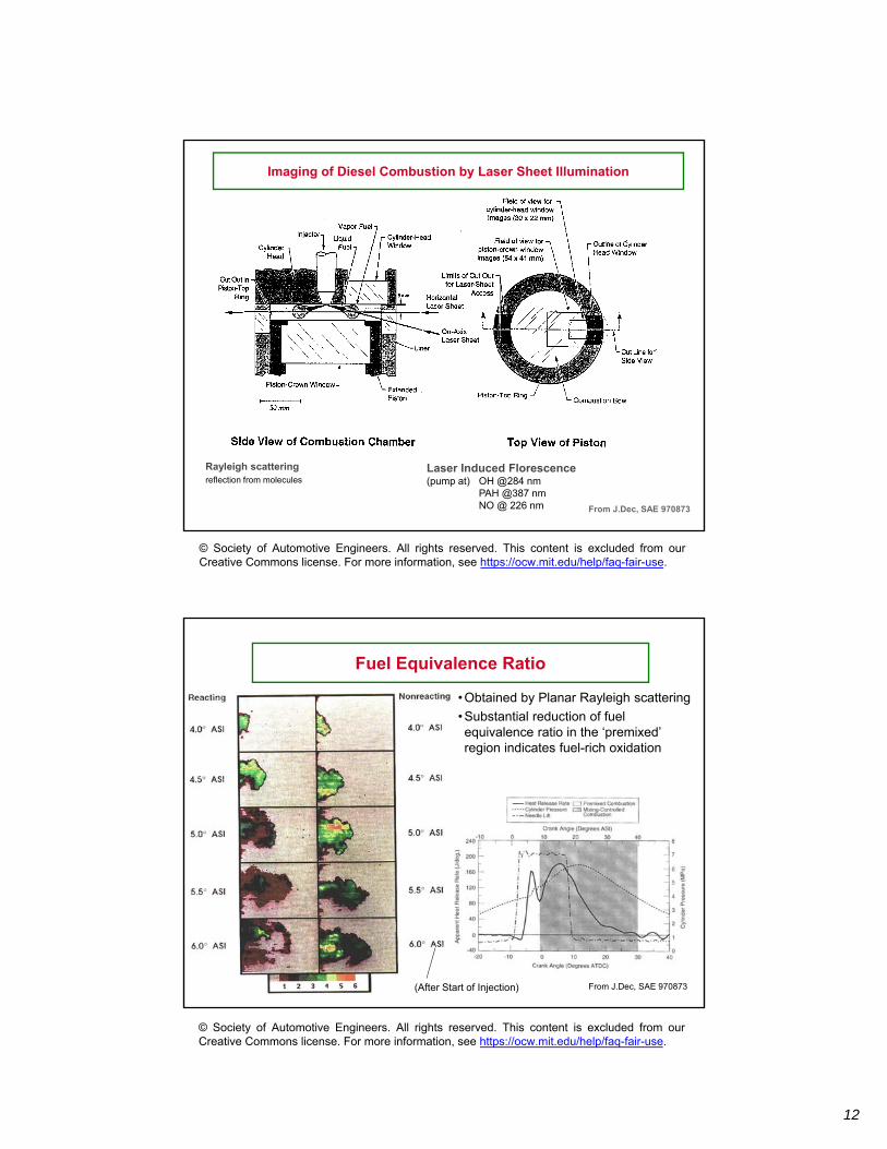
Imaging of Diesel Combustion by Laser Sheet Illumination
Rayleigh scattering Laser Induced Florescence reflection from molecules (pump at) OH @284 nm
PAH @387 nm NO @ 226 nm From J.Dec, SAE 970873
© Society of Automotive Engineers. All rights reserved. This content is excluded from our Creative Commons license. For more information, see https://ocw.mit.edu/help/faq-fair-use.
Fuel Equivalence Ratio
• Obtained by Planar Rayleigh scattering
• Substantial reduction of fuel equivalence ratio in the ‘premixed’ region indicates fuel-rich oxidation
From J.Dec, SAE 970873 (After Start of Injection)
© Society of Automotive Engineers. All rights reserved. This content is excluded from our Creative Commons license. For more information, see https://ocw.mit.edu/help/faq-fair-use.
12
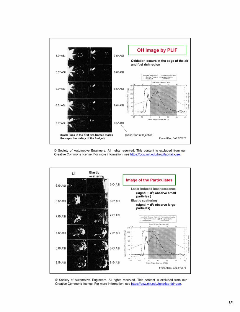
OH Image by PLIF
Oxidation occurs at the edge of the air and fuel rich region
From J.Dec, SAE 970873 (Dash lines in the first two frames marks the vapor boundary of the fuel jet)
5.0o ASI
5.5o ASI
6.0o ASI
7.0o ASI
6.5o ASI
8.0o ASI
7.5o ASI
9.0o ASI
8.5o ASI
9.5o ASI
(After Start of Injection)
© Society of Automotive Engineers. All rights reserved. This content is excluded from our Creative Commons license. For more information, see https://ocw.mit.edu/help/faq-fair-use.
ElasticLII scattering
6.0o ASI6.0o ASI
Image of the Particulates
Laser Induced Incandescence (signal ~ d3; observe small particles )
6.5o ASI Elastic scattering (signal ~ d6; observe large particles)
6.5o ASI
7.0o ASI7.0o ASI
7.5o ASI 7.5o ASI
8.0o ASI 8.0o ASI
8.5o ASI 8.5o ASI
From J.Dec, SAE 970873
© Society of Automotive Engineers. All rights reserved. This content is excluded from our Creative Commons license. For more information, see https://ocw.mit.edu/help/faq-fair-use.
13
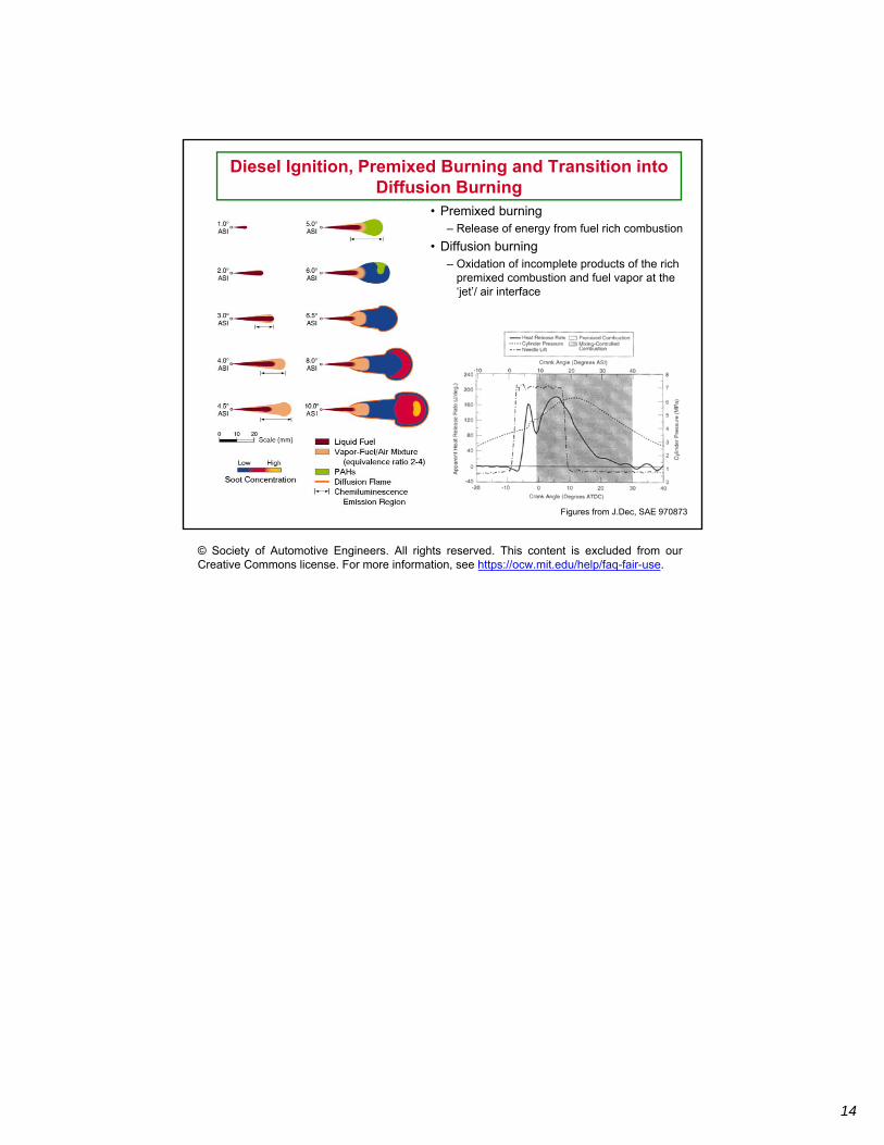
Diesel Ignition, Premixed Burning and Transition into Diffusion Burning
• Premixed burning – Release of energy from fuel rich combustion
• Diffusion burning – Oxidation of incomplete products of the rich
premixed combustion and fuel vapor at the ‘jet’/ air interface
Figures from J.Dec, SAE 970873
© Society of Automotive Engineers. All rights reserved. This content is excluded from our Creative Commons license. For more information, see https://ocw.mit.edu/help/faq-fair-use.
14
MIT OpenCourseWare https://ocw.mit.edu
2.61 Internal Combustion EnginesSpring 2017
For information about citing these materials or our Terms of Use, visit: https://ocw.mit.edu/terms.