Embed Size (px)
Citation preview

8/8/2019 Dielectric Resonators for Mobile
http://slidepdf.com/reader/full/dielectric-resonators-for-mobile 1/4
Dielectric Resonators for Mobile
Communication Applications
D. BUDIMIR, N. NIKOLIC and G. SHEN
Wireless Communications Research Group, Department of Electronic Systems,
University of Westminster, 115 New Cavendish Street,
London W1W 6UW, United Kingdom.
Abstract: - This paper presents the results of the Computer Aided Design of high-Q dielectric
resonators of three different configurations. The resonators were designed and simulated for their
electromagnetic performance using HFSS commercial software and the results with respect to the
Q-factor were compared.
Key-Words: - Dielectric resonators, periodic structures, Filters, mobile communication, Q-factor.
1. Introduction
It has long been recognised that the use of
high permittivity dielectric materials offer
large reductions in size and weight compared
to conventional waveguide filters. However,
only recent advances in material technology
have made it possible to combine high Q,
good thermal stability and high dielectric
constant in materials suitable for use at
microwave frequencies. Riding on these
technological advances, many researchers
have pursued work and as a result new types
of dielectric filters [6] such as Image quarter-
cut dielectric resonator filters have been
introduced. These configurations offer very
compact structure yet capabilities to handle
much higher power level. The
configurations are based on TE011 and
HE111 resonant modes of cylindrical
dielectric disk symmetrically positioned in a
square cross-section cavity.
The electromagnetic field patterns are
relatively complex in such partially-loaded
cavities. The novel concepts involve taking
advantage of the electromagnetic field
structure of these resonance modes to create
a quasi-multi mode resonance regime within
the cavity. This is done by introducing
electrically-conducting surfaces within the
cavity which intersect the dielectric disk, so
splitting the normal resonating modes into
several parts. Each of these modes resonatesat the same frequency as before, but
independently of each other until inter-
coupled by some means. The potential
advantages of this configuration are
substantial savings in size and mass together
with the possibility of easy removal of the
heat generated within the resonator.
However, the main disadvantage with the
image resonator is a reduction in Qu-factor
as compared with the equivalent full disc
resonator. This is because the metallic
intersecting walls are in direct contact with
surfaces of the dielectric segment and
therefore in close proximity with strong
electromagnetic fields which are
concentrated within the segment. This
principle was verified through a CAD for
quarter-cur dielectric resonator and three-
quarter-cut dielectric resonator band-pass
filter for PCN applications [2].
By replacing the inner conductor of the
conventional combline resonator by a high εr dielectric rod, a new type of resonator is
proposed [3] for satellite base-stations which
offers high unloaded-Q and the merits of the
metallic combline resonator and dielectric
loaded resonator. As an experiment, a
revised configuration is formed by mounting
one or more high-Q dielectric rings onto the
cylindrical rod. The physical structure takes
the form of slotted penetration of disks
mounted on a cylindrical rod, contained
within a metallic enclosure.

8/8/2019 Dielectric Resonators for Mobile
http://slidepdf.com/reader/full/dielectric-resonators-for-mobile 2/4
Using Hewlett--Packard's High Frequency
Structure Simulation (HP-HFSS),
electromagnetic simulations are done in the
lab for all these three structures and the
results are compared mainly for the
improvements in the Q factor.
2. Resonators
The quarter-cut dielectric resonator is shown
in figure 1. The dielectric for the resonator
was Alpha-Trans-Tech, Inc., 8300 series
with the permittivity = 35.065.
Figure 1. Quarter-cut DR.
The resonator by replacing the inner conductor of a conventional combline
resonator with a dielectric rod is shown in
Figure 2. A dielectric cylindrical rod is
placed at the centre of metallic box. The
excitation is done through the coaxial probes
penetrating through the sidewalls of the
metallic enclosure.
Figure 2. Modified dielectric resonator
In the second configuration, the height of the
dielectric is reduced but three short dielectric
rings are mounted on to the cylindrical rod as
shown in the Figure 3.
Figure 3. Conventional dielectric resonator
3. CAD and Simulation
The design and simulation of the resonators
were done using Hewlett-Packards HighFrequency Structural Simulator (HFSS)
software. To generate an electromagnetic
field solution from which S-parameters can
be computed, HFSS employs the finite
element methods, in which divides the
problem space is divided into thousands of
smaller regions and represented the field in
each sub-region (element) with a local
function. In HFSS, the geometric model is
automatically divided into a large number of
tetrahedral, where a single tetrahedron is
formed by four equilateral triangles. Thiscollection of tetrahedral is referred to as the
finite element mesh. A mesh is the basis
from which a simulation begins. Initially,
the structure's geometry is decomposed into
meshes by iterative adding vertex points
(seeding). In the case of adaptive
refinement, the initial field solution is
progressively refined.
The design was reviewed after each
simulation run and the modifications were
applied to the physical parameters of the
Dielectric Rod
Aluminium Enclosure
Coaxial Output
Aluminium Enclosure
Coaxial Output
Coaxialinput
Dielectric Rings
8/8/2019 Dielectric Resonators for Mobile
http://slidepdf.com/reader/full/dielectric-resonators-for-mobile 3/4
configuration until required results were
achieved.
4. Experimental Results
The quarter-cut dielectric resonator has aceramic puck of 30 mm diameter by 18mm
high mounted in a cavity 192.30 mm square
by 51.28 mm high. The resonator was tested
for the central frequency 1810 MHz. The
figure 4 shows the measured resonant
frequency of quarter-cut TE01δ image
resonator.
Figure 4. Measured resonant frequency
The conventional dielectric resonator as
shown in Figure 2, has the dielectric at thecentre with 6.35 mm radius and 23.0 mm
height. The enclosure was a rectangular
square of 44 mm and height 27mm. The
coaxial probes for the excitation were of 3.0
mm outer radius and 1.5 mm inner radius
with the penetration length of the coaxial
probe was 6mm from the inside wall.
The modified dielectric resonator as shown
in Figure 3, has the dielectric at the centre
with 6.35 mm radius and 21.0 mm height.
There were three circular dielectric disks
(radius 8.35 mm, height 3.5 mm) mounted on
the central rod. The enclosure was a
rectangular square of 44 mm and height
27mm. The coaxial probes for the excitation
were of 3.0 mm outer radius and 1.5 mm
inner radius with the penetration length of
the coaxial probe was 6mm from the inside
wall. In both cases the dielectric permittivity
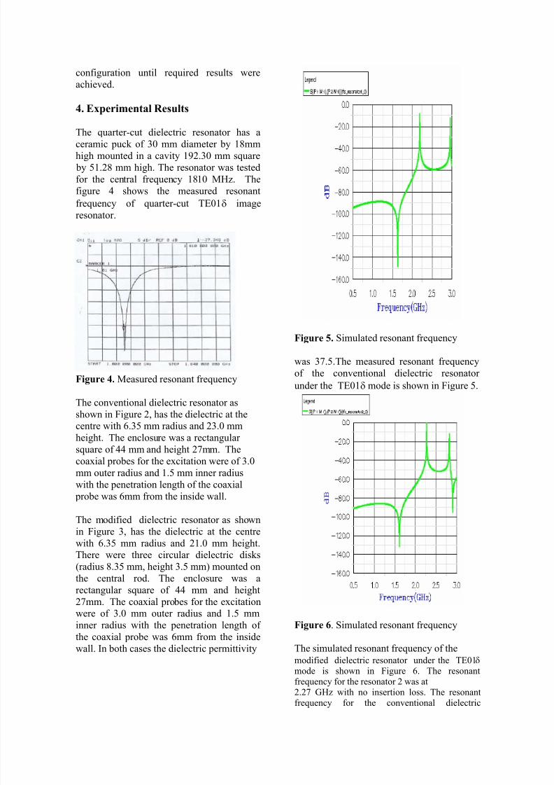
Figure 5. Simulated resonant frequency
was 37.5.The measured resonant frequency
of the conventional dielectric resonator
under the TE01δ mode is shown in Figure 5.
Figure 6. Simulated resonant frequency
The simulated resonant frequency of the
modified dielectric resonator under the TE01δ mode is shown in Figure 6. The resonantfrequency for the resonator 2 was at2.27 GHz with no insertion loss. The resonantfrequency for the conventional dielectric

8/8/2019 Dielectric Resonators for Mobile
http://slidepdf.com/reader/full/dielectric-resonators-for-mobile 4/4
resonator 1 was at 2.19 GHz with the insertionloss of –12dB. Further experiments were carriedout in the conventional dielectric resonator by
modifying the dimensions in order to get thecentral frequency as that of the enhancedresonator.
The simulated resonant frequency of the
conventional resonator after the modification
was shown in Figure 7. The plot shows the
S12 values for the final configuration of
Resonator 1 when the resonant frequency
2.276GHz is closest to the reference
configuration (Resonator 2) and the insertion
loss is 1.5dB. For this configuration, the size
of the coaxial probes and the penetration
length were reset to the original
configuration but their co-ordinates were
changed in the z-direction (upwards).
Figure 7. Simulated resonant frequency
5. Conclusion
In this paper, we are investigating dielectric
resonators for the filters which can replace
combline filters to give equivalent
performance at a smaller size. In the case of
quarter-cut dielectric, the Qu factor was
measured to be 3600. In the case of
conventional dielectric resonator as shown in
Figure 1, the measured Qu-factor was 2190
with the insertion loss of 12dB. In the case of
enhanced dielectric resonator as shown in
Figure 3, the Qu factor was 2837 with no
insertion loss. At L-band frequencies,dielectric resonators are used as single
cavities in combines or as very narrowband
notch filters. In each case very high Q
values are required and any size reduction
must be compared with an equivalent
waveguide cavity design.
References
[1] R.J. Cameron, “Microwave Filters
for Spacecraft Systems”, M/RF Conference
Proc. October 1995, PP 75-180
[2] Djuradj Budimir , “Quarter-cut
Dielectric Resonator Bandpass Filters for
Mobile Radio Communication Base
Stations”
[3] Chi Wang et al, “Dielectric
Combline Resonators and Filters”, IEEE Trans. Microwave Theory Tech., vol. 46, No
12, Dec 1998