Embed Size (px)
Citation preview

rflD-Ai52 88 RUTOMATED POLYMER DIE ATTACH NACHINE(U) HUGHES AIRCRAFT i/ICO TUCSON AZ TUCSON MFG DIY G M COPPUS ET AL.13 JAN Bi DAH~i-8i-D-A@8I
UNCLSSIFIED F/6 03/9 N

A 4 11111N~2.2* 1.8
11111L25 11111__.4 111111. 6
MICROCOPY RESOLUTION TEST CHART
N W AI
- - - -. - - - ... .-- -.
AUTOMATED POLYMER DIE ATTACH MACHINE
I.I
oo HUGHES AIRCRAFT COMPANYC" TUCSON MANUFACTURING DIVISION
------ -- - - - --- -S: HUGHES
MUGMI A1MCFRA ' CO4PAII
I ~*DT1C i
I ' Prepared for: '-IJU.S. Army Missile Command
- System Engineering DirectorateATTN: DRMSI-RHS
.... Redstone Arsenal, 35898
85 01 1') 1.13- *... *.

IA
cReport DAAHO-81-D-AOO
AUTOMATED POLYMER DIE ATTACH MACHINE
G. M. Coppus/G. N. HunterHughes Aircraft Company
I Tucson Manufacturing Division'L P. 0. Box 11337
Tucson, AZ 85734II
13 January 19,1
* IU Initial Report
* I
fAccession For
~DTIC T,-
INSpt;~ Iu!)
Prepared for: .. -
By-U. S. Army Missile Command Distr,
System Engineering Directorate Avaj •ATTN: DRMSI-RHS
* Redstone Arsenal, AL 35898
I
• 1
j SECURITY CLASSIFICATION OF THIS PAGE (When Date Entered),
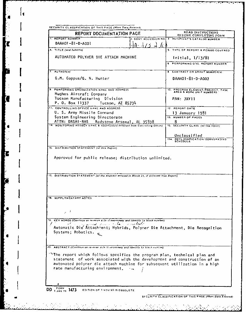
REPORT DOCUMENTATION PAGE RFAD INSTRUCTIONSBFI-ORE COMPLETING FORM
II. REPORT NUMB3ER 2. GOVT ACCESSION No. 3 RECIPILNT'S CATALOG NUMB3ER
4. TITLE (and Subtitle) /5. TYPE OF REPORT & PERIOD COVERED
AUTOMATED POLYMER DIE ATTACH MACHINE Initial, 1/13/816 PERFORMING O1G. REPORT NUMBER
7. AUTNOR(s) 8. CONTRACT OR GRANT NUMaER(s)
G.M. Coppus/G. N. Hunter DAAHOI-81-D-A002
9. PERFORMING ORGANIZATION NAME AND ADDRESS 10. PROGRAM ELEMENT. PROJECT. TASKHughes Ai rcraft Company AREA & WORK UNIT NUMBERS
Tucson Manufacturing Division PAN: 7RYIIP. 0. Box 11337 Tucson, AZ 85734
1I. CONTROLLING OFFICE NAME AND ADDRESS 12. REPORT DATE
U. S. Army Missile Command 13 January 1981System Engineering Directorate 13. NUMBEROF PAGESATTN: DRSMI-RHS Redstone Arsenal, AL 35898 8
14. MONITORING AGENCY NAME 6 ADDR ESS(II different fromn Con:r,!Nng Ofhce) 15. SECURITY CLASS. (of this report)
1 [I Unclassified15 a. DECL ASSI FI C ATION' DOWN 6R A IN G
SCHEDULEJ IS. DISTRIBUTION STATEMENT (of his Report)
Approved for public release; distribution unlimited.
I17. DISTRIBUTION STATEMENT (of ".',e abstract entered in Block 29, i different from Report)
1IS. SUPPLEMENTARY NOTES
* 119. KEY WORDS (Continue on reverse sis it necessary and identify !7y blnck number)* I/ . 'I, . . . . , , ... ., C . . .. c ,
Automatic Die ttachment; Hybrids, Polymer Die Attachment, Die RecognitionSystems; Robotics.
20. ABSTRACT (Continue on reverse ide If necessary end Identify S., b:ock nu-,t'r)
.!The report which follos specifies the program plan, technical plan and
statement of work associated with the developrent and construction of anqI automated polymer die attach machine for subsequent utilization in a high
rate manufacturing environment. -, /
FORM
DD JAN 73 1473 EDITION OF I NOV 65 IS OBSOLETE
- SFCUITY CLASSIFICATION OF THIS PAGE (4te'n bate Entered)

Sii ITECHNICAL REQUIREMENT
IAutomated Polymer Die Attach M'achine
1.0 General
[...The current trend throughout the military hybrid industry is thereduction of operator controlled variables in an effort to reducecost while maintaining or increasing equipment volume handlingI capability.-,,n important area in which this can be accomplishedis in the chip to substrate assembly operation. Existing equip-ment is designed for operator recognition and orientationalingment of individual semiconductor chip topographies.- Thepurpose of this manufacturing technology program is to developa semi-automatic chip recognition Die Bonding System.__he systemmust present a video image of the die to be placed on a TV Monitor. .1'This image shall be overlayed with an outline image of the die toshow correct orientation of said die. The operator will then alignthis overlayed image to the real die. The machine will then pickup, orient, and place the die in correct orientation on the sub-strate without operator control. This system must be applicableto a future fully automatic hybrid die bonder.I
2.0 Applicable Documents
12.1 MI-T-8
32.21 3.0 Requirements
* 3.1 Technical Effort
The contractor shall provide the personnel, materials, equipment,and expertise required to perform the tasks hereinafter required.
3.2 Planning
The technical effort to be conducted under these requirements willbe planned in terms of technical tasks and related objectives to be
I |accomplished in the pursuit of the entire program. Each task andrelated objective will result in the completion of a significant
* portion of the total effort. The following outline describes these" aforementioned tasks and objectives and a milestone chart for com-" I pletion of the outlined items is included in the program plan portion
of this report.
• I ~
o - -. . . . .
• " ': -' . > -i '- " i . i- i i.. i J .. , ". ,' - : > ." - . -% -i T ; . > - -. ' " - .i -. . " > . % . -> " -- . . - -.. "
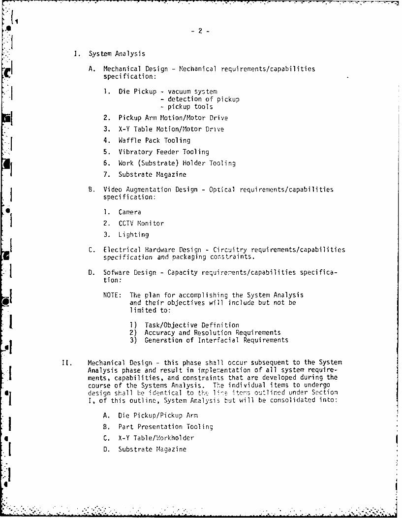
I. System Analysis
A. Mechanical Design- Mechanical requirements/capabilitiesspeci fi cation:
1. Die Pickup - vacuum system- detection of pickup- pickup tools
2. Pickup Arm Motion/Motor Drive
3. X-Y Table Motion/Motor Drive
4. Waffle Pack Tooling
5. Vibratory Feeder Tooling
6. Work (Substrate) Holder Tooling
7. Substrate Magazine
B. Video Augmentation Design - Optical requirements/capabilitiesspecification:
1. Camera
2. CCTV Monitor
3. Lighting
C. Electrical Hardware Design - Circuitry requirements/capabilitiesspecification and packaging constraints.
D. Sofware Design - Capacity require.ents/capabilities specifica-tion:
NOTE: The plan for accomplishing the System Analysisand their objectives will include but not belimited to:
1) Task/Objective Definition2) Accuracy and Resolution Requirements3) Generation of Interracial Requirements
II. Mechanical Design - this phase shall occur subsequent to the SystemAnalysis phase and result in implementation of all system require-ments, capabilities, and constraints that are developed during thecourse of the Systems Analysis. The individual items to undergodesign shall be identical to the 1ie itemrs outlined under SectionI, of this outline, System Analysis but will be consolidated into:
A. Die Pickup/Pickup Arm
B. Part Presentation Tooling
C. X-Y Table/W1orkholder
D. Substrate Magazine
*1 .

I;-3-
III. Video Augmentation - This phase shall also occur subsequentto the System Analysis phase and results in, again, theimplementation of all systems recuirements, capabilitiesand constraints that are developed during the course of theSystems Analysis.
IV. Hardware/Software Design - Tie in of individual components:
A. Hardware I With respect to both hardware and softwarethe aforementioned mechanical and videoB designs of individual components shall beintegrated resulting in full-up subsystemdesign development and associated packaging.
V. Final Design (Prototype) - in this last phase of developmentthe previously mentioned Hardware/Software subsystems shall bepackaged into a final unit concept which will be subsequentlyassembled into a working prototype allowing performance evalu-ation of the individual components and subsystems.
The plan for performance of Sections I" through V identified above
shall include but not be limited to:
1) Performance - specification ceneration
2) Drawing development
3) Components and Materials selection
4) Procurement of vended components and materials.
3.3 Description of Effort to be Performed
3.3.1 General Description
The hybrid die bonder is to be a semi-automatic computer-controlled system for attaching semiconductor die componentsto ceramic substrates. The dies are bonded to the substrateby utilizing pre-screened epoxy. The system will be composedof a pick and place arm, a sutstrate workholder with auto-matic substrate feed from magazines and an array of up toforty-two 2 x 2 inch waffle packs or a combination of wafflepacks and linear vibratory chio feeders.
In operation, a substrate is automatically fed by the work-holder from the magazine to the bond site and clamped into
position. The position of the substrate is aligned to cross-I hairs on a CCTV monitor. Following pretaught instructions,the computer will direct the nick and place arm to the properwaffle pack where the next available die is displayed on themonitor. The amount of die Fisalignment and its orientationis determined by image correlation techniques. The die is
-,. -S . ._ - . -..t. : . . -..v v t - t .. . .. . --. . . . -. - . -

_4
then picked up and placed in its proper orientation on
the substrate. This cycle will continue until the sub-strate has been completely bonded. The substrate isthen fed into the output magazine and replaced by a newone and the process continues. The computer monitors thenumber of die in each waffle pack or feeder and willsignal via the CCTV monitor when a waffle pack must be[replaced or feeder refilled. Waffle pack trays andfeeders slide out from under the machine cover to allowthe operator to quickly replace or refill them. Whenall substrates have been completed, the system auto-matically stops.
3.3.2 Alignment Accuracy
The chip recognition system shall be capable of positioningcomponents within + .002 inches of the exact position andwithin + 5 degrees of the exact orientation.
3.3.3 Production Rates
The semi-automatic system must have a through-put of 25or more substrates per hour with approximately 30 dies persubstrate.
3.3.4 Configuration
3.3.4.1 Overall Dimensions
The system size will be approximately 48 inches wide x 36inches deep x 50 inches high or less and will occupy floorspace of approximately 48 inches wide x 48 inches deep orless.
3.3.4.2 Substrate Feed
Substrates must be fed automatically from magazines orequivalent and cycle at approximately two (2) seconds orless.
3.3.4.3 Waffle Pack Capacity
The system must accommodate approximately forty-two (42)2 x 2 inch waffle packs (Flourware type or equivalent)from which die may be selected.
SI

5
3.3.4.4 Vibratory Chip Feeder
( The system must provide for up to eight chip feeders.The maximum number of waffle packs (3.3.4.3) may bereduced to thirty-six (36) if eight feeders are con-figured.
3.3.5 Other Requirements
The system shallonot subject the substrate to temperaturesin excess of 100 F. The system shall not damage devicesbeing attached to substrates. The system shall have anemergency stop capability.
4.0 Documentation
4.1 The contractor shall prepare a final report detailing theinvestigations, tests, and data collected during the courseof this project. Data to be delivered, schedule of delivery,and distribution requirements are specified on DO Form 1423.The final report shall contain an outline of the work per-formed, a general description of the developed manufacturingequipment (with references), a technical description of theS! process; and shall contain all the material, either withinthe reports or within the references required to duplicatethe equipment and technology. Other reports required shallbe as listed on DD Form 1423.
I 4.2 The contractor shall propose, to the Government, an imple-I mentation plan which details the steps to be taken by the
contractor to implement the results of this effort. TheI implementation plan shall cover those facilities owned and/
or operated by the contractor and those subcontractedfacilities participating in this contract. The primary
jO i emphasis of the implementation plan shall be Army Hissilej Systems and end items/components of Army Missile Systems
currently under development or production by the contractor.Data as to the applicability of this project's results toAir Force and/or Navy development/production efforts isalso of importance and shall be addressed in the imple-mentation plan.i
4.3 The contractor shall provide a 10 minute narrated video tape,and a set of fifty (50) 35n , color slides depicting the manu-facturing process, suitable as a familiarization and instruc-tional tool. The deterriination on the exact content andmethod shall be by the contractor with Government approval.Delivery shall be at the conclusion of the contract.
I
, .- • * .. - .-
6
4.4 The contractor shall orally review the progress of thework to the Government at quarterly intervals, at mutuallyagreeable times and places. Other reviews, if determinednecessary by the Government, shall not exceed three (3)per year.
4.5 The contractor shall perform an industry deronstration.The contractor shall give the Government sixty (60) daysnotice prior to demonstration.
.!i
.- - -. . - - { . " . . ,' " - -. -, . . •

*I,IC Program Plan for Tasks Concerning Automated Polymer Die
Attach MachineI
1.0 General
1This program plan identifies the work to be completed during theperformance of MICON Project #3219, "Automated Polymer Die AttachMachine". The majority of work completed shall occur at Kulickeand Soffa (K & S), equipment manufacturer, with Hughes Aircraftin an overseers capacity ultimately resulting in buy-off of systemconcept and prototype performance as identified in the TechnicalRequirements sections of this report.
T
i 2.0 Milestones
The attached chart displays the major items to be completed, the
t time required and the sequence of eveits of each.
i
!.
*,1
*1•
* II
- . -.- ..-.-.

SHUGHES MICOM PROJECT NO. 3219PROGRAM NO PROGRAM TITLEP
W3S ITEM NOMENCLATURE DESCRIPTION:
V S .AUTOMATED POLYMER DIE ATTAc
_WS LEVE L- COST ACCT. NO.
CRG 3RESP. ACTIVITYIEVENT DESCRIPTION MONTHS AFTER GO-AHEAD
0 ___T-J-
I System Analysis Lz z VII A. r!iech Design Analysis AA I- H
1. Die Pickup A-------_,Z ,2. Pickwq Arm A LL3. X-Y Table z -_ _
4. 'affle Pack Tool in2 *
S. Vibratory Feeder Tcolinr- -
"- G. orkholder Toolinc-
____ 7. Suhs trae "lacaz i A."KE_ . Video Augnentation A
C '1 ____ _ L.CCT'V 71onitor--- -
3 L Li g t inq A_
f_ C. Electrical Hdr. Desizn -
___ D Software Desirn j1I I flechanical Desi on
I A. Die PickuP/Picku) Art, - - - ----- -
I B. Part Presentation Toolinr__
__--_ C, X-Y Table/Workholder, I O0. Substrate Hflaazine
II Video Auljqentation II' hard,.are/Software Design
* f . ~r(%,are
____ B. Software j - /9
SFinal Des ifn LPrototmJ1
____ pDo r t i rw ___- IFilm___
CUT-OFF DATE
15213C Cf, 5 P 76

ORGANIZATION PAGE 1 OF_
I RESPONSIBILITY
kCHINE NAME ORG CODE EXT.
j CONTRACT NO. REFERE CE NO. PROD. LINE
SCHEDULE
.9
8 9 10 11 12
-- - - I,_ I-I' I -- .,
ILI. . . . .. . .. _ _ _ _ _ _ - ST
__ - , - !__._---- ,
-.. "!. .. {. . "1 i __ _ __ _ _
- ,!t Ka K HI I i[L K
.. . L i .. I
.- t- r - [ ! 1 ! i-- I :J !i - 1i: r ' '
• . ... l i ....-- - - - - -I
_ -..... . . . ... . . . . - .
6PREPARED ElY OPV, CODz. EST.
FILMED
* 4-85
* DTIC