Embed Size (px)
Citation preview
ITTC Dictionary of Hydromechanics
Version 2011
1
Dictionary of Hydromechanics
Alphabetic
Prepared by the Quality Systems Group of the 26th ITTC
• M. Ferrando, University of Genova, Italy (Chairman) • L. Benedetti, INSEAN, Italy (Secretary)
• A. Ito, IHI, Japan • B. Johnson, US Navy Academy, USA (senior) • S.H. Rhee, Seoul National University, Korea
Version 2011 07/08/2011
ITTC Dictionary of Hydromechanics
Version 2011
2
Original INTRODUCTION This Dictionary is intended for a broad readership including practising naval architects who wish to acquire and apply knowledge of hydrodynamics and also physicists and theoretical hydrodynami-cists who wish to apply their particular knowledge to the solution of ship problems. Engineering, physical and nautical terms in common use have not been included when did not re-quire special definition in the context of ship hydrodynamics or when their meanings were self evi-dent. The work is arranged in the following sections prefaced with a brief reference to the nature if their content:
1. General 2. Vessel Geometry and Stability 3. Resistance 4. Propeller (including propeller geometry) 5. Cavitation 6. Seakeeping 7. Manoeuvrability 8. Performance ( in the context of speed and power)
The order of entry for each item is: title, symbol, dimensions, followed by the definition. In each section the titles are arranged in alphabetical order. In this way, having found the item required, pe-rusal of the section will indicate other related items which may be of interest. For general reference, there is an overall alphabetical index of all titles and against each is given the section and page where the item is to be found. The symbols given are in accordance with those in the latest ITTC symbols list which is a comple-mentary document. In a number of instances, the list give alternative symbols and these are gener-ally included except where a definite preference is indicated.
Comments on the new Dictionary format: The ITTC QS Group had already started a new Dictionary in A4 paper format in MSWord 2007-10. The current draft is also in .docx format for both the A4 and 81/2 by 11 inch versions. This is be-cause some of the figures do not translate properly back to MSWord 2003. It is distributed for re-view in Acrobat format to make printing easier. For editing purposes, single column format is much preferred over double column format where en-tries tend to jump around, especially explanatory figures. Since this is to be a web based document, continuously updated (possibly in wiki style), single column format may be preferred even for the current status of the dictionary. Note also that the old Dictionary has the concept on a separate line which increases the size of the dictionary. The new material uses a hanging indent to set off the name of the entry in bold and/or italics. For this draft, blue fonts were initially used to indicate new subjects and definitions. Items needing clarification are those in red fonts. The figure captions need to be made independent of the order in which they appear in each edition. Since the ITTC Dictionary of Hydromechanics will be updated by the QS Group using the wiki approach and other inputs, a numbered set of figures may not be appropriate but are continued for the present.
ITTC Dictionary of Hydromechanics
Version 2011
3
A Acceleration zone (cavitation) In the sequence of cavitation erosion, the zone of the curve of weight loss versus time in which a rapid increase in weight loss occurs (the region between the incubation zone and the deceleration zone which see). Formerly called the Accumulation zone.
Active rudder (propulsion, propulsor) See: Rudder, active
Added mass (seakeeping) [M] The total hydrodynamic force, per unit acceleration, exerted on a ship or other body in phase with and proportional to the acceleration.
Added mass coefficient (seakeeping) (Aij) [-] A non-dimensional coefficient expressing added mass (which see) in ith mode due to jth motion.
Admiralty coefficient (performance) A quasi-dimensionless coefficient used for assessing or comparing the performance of ship. Admiralty coefficient = 𝛥
23𝑉3/𝑃, where ∆ is the displacement, V speed and P any corresponding
power.
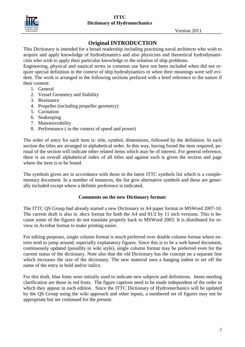
Advance (manoeuvring) The distance by which the centre of gravity (CG) of a ship advances in the first quadrant of a turn. It is measured parallel to the approach path, from the CG position at rudder execute to the CG position where the ship has changed heading by 90 degrees (See Figure 1). Maximum advance is the dis-tance, measured parallel to the approach path from the CG position at rudder execute to the tangent to the path of the CG normal to the approach path. The first of these terms is that most commonly used.
Figure 1: Geometry of turning circle
ITTC Dictionary of Hydromechanics
Version 2011
4
Advance angle (of propeller blade section) (propulsion, propulsor) See: Angle, advance
Advance angle, effective (propulsion, propulsor) See: Angle, effective advance
Advance coefficient (propulsion, propulsor) (J) [-] A parameter relating the speed of advance of propeller, VA to the rate of rotation, n, given by
AJ V nD , where D is the propeller diameter. The advance coefficient may also be defined in
term of ship speed, V, in which case it is given by: VJ V nD .
Advance coefficient, Taylor’s (propulsion, propulsor) (δ) A parameter defined as:
𝛿 = 𝑛𝐷 𝑉A⁄ = 101.27 𝐽⁄
where n is the rate of propeller rotation in revolution per minute, D is the propeller diameter in feet, and VA is the speed of advance in knots.
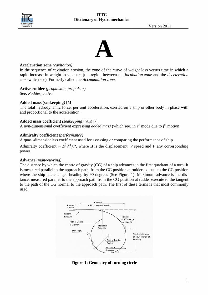
Advance maximum (in stopping) (manoeuvring) The distance travelled by a ship, in the direction of the approach path, before coming to rest after having executed a crash-back manoeuvre from a steady, straight-line motion ahead; it is also called Headreach. (See Figure 2). See also: Transfer, maximum (in stopping).
Figure 2: Crash stop manoeuvre
ITTC Dictionary of Hydromechanics
Version 2011
5
Advance ratio (propulsion, propulsor) (λ) [-] A non dimensional speed parameter relating the speed of advance, VA and the rotational tip speed, πnD, given by:
𝜆 = 𝑉𝐴 𝜋𝑛𝐷⁄ = 𝐽 𝜋⁄ where J is the advance coefficient, D is propeller diameter and n its rate of rotation.
Advance, speed of (propulsion, propulsor, performance) See: Speed of advance.
Air content(cavitation) The term used loosely to describe gas content (which see) when gas content is composed of compo-nents of air in the liquid.
Air content ratio(cavitation) See: Gas content ratio.
Air, still, resistance (performance) See: Resistance, wind.
Amidships (vessel geometry and stability) (sometimes con- tracted to midship) ( ) [-] Near the centre of ship length, specially, the section of the ship at mid length (See Errore. L'ori-gine riferimento non è stata trovata.)
Amplitude (seakeeping) Extreme value of a sinusoidal quantity with respect to the mean value.
Analysis pitch (propulsion, propulsor) See: Pitch, analysis.
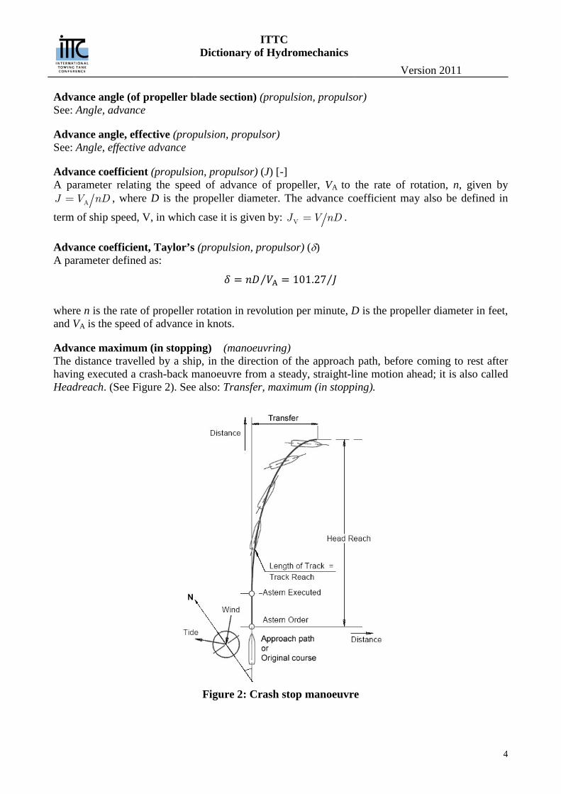
Angle, advance (of a propeller blade section) (propulsion, propulsor) (β) [-] The inflow angle to a propeller blade section determined by the rotative speed, ω r, the axial veloc-ity of the fluid, VX, and the tangential velocity of the fluid Vθ, according to the equation:
𝛽 = tan−1{𝑉𝑋(𝑟,𝜃)/[𝜔𝑟 − 𝑉𝜃(𝑟,𝜃)]}
r is the radius of the blade section, ω the angular rate rotation and θ the angular position of the blade section. A simpler definition, also in use is:
𝛽 = tan−1(𝑉A 𝜔𝑅⁄ ) where R is the propeller radius and VA the advance speed. The induced velocities are not included in the determination of the advance angle (See Figure 3).
Angle of attack (propulsion, propulsor, manoeuvring)) (α) [-] The angle measured in the plane containing the lift vector and the inflow velocity vector, between the velocity vector representing the relative motion between a body and a fluid and a characteristic line or plane of the body such as the chord line of an airfoil or hydrofoil, positive in the positive sense of rotation about the y-axis. (See: Axes, co-ordinate in General Section). Synonymous with angle of incidence.
ITTC Dictionary of Hydromechanics
Version 2011
6
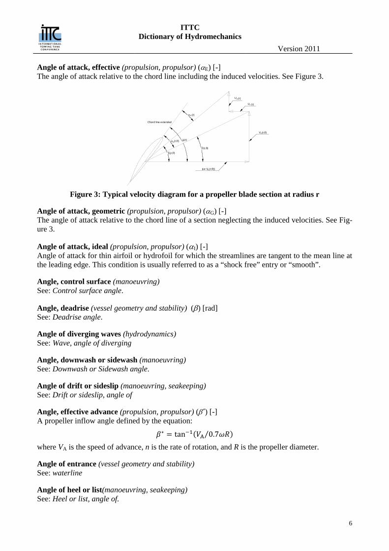
Angle of attack, effective (propulsion, propulsor) (αE) [-] The angle of attack relative to the chord line including the induced velocities. See Figure 3.
Figure 3: Typical velocity diagram for a propeller blade section at radius r
Angle of attack, geometric (propulsion, propulsor) (αG) [-] The angle of attack relative to the chord line of a section neglecting the induced velocities. See Fig-ure 3.
Angle of attack, ideal (propulsion, propulsor) (αI) [-] Angle of attack for thin airfoil or hydrofoil for which the streamlines are tangent to the mean line at the leading edge. This condition is usually referred to as a “shock free” entry or “smooth”.
Angle, control surface (manoeuvring) See: Control surface angle.
Angle, deadrise (vessel geometry and stability) (β) [rad] See: Deadrise angle.
Angle of diverging waves (hydrodynamics) See: Wave, angle of diverging
Angle, downwash or sidewash (manoeuvring) See: Downwash or Sidewash angle.
Angle of drift or sideslip (manoeuvring, seakeeping) See: Drift or sideslip, angle of
Angle, effective advance (propulsion, propulsor) (β∗) [-] A propeller inflow angle defined by the equation:
𝛽∗ = tan−1(𝑉A 0.7𝜔𝑅⁄ ) where VA is the speed of advance, n is the rate of rotation, and R is the propeller diameter.
Angle of entrance (vessel geometry and stability) See: waterline
Angle of heel or list(manoeuvring, seakeeping) See: Heel or list, angle of.
α )θ(r,G
)β(r,θ
)(r,θVX
(ω θr-V ))(r,θ
βI θ)(r,
TU (r)
AU (r)
(r)Eα
φ(r)
Chord line extended
ITTC Dictionary of Hydromechanics
Version 2011
7
Angle of heel or roll, projected (manoeuvring) (or angle of attack in roll) (γ) [-] The angular displacement about the x0 axis of the principal plane of symmetry from the vertical, positive in the positive sense of rotation about the x0 axis. (See: Axes, co-ordinate).
Angle, hydrodynamic flow (propulsion, propulsor) (βI) [-] The inflow angle to a propeller blade section including the axial and tangential induced velocities given by the equation:
𝛽I = tan−1 �𝑉𝑋(𝑟,𝜃) + 𝑈A(𝑟)
𝜔𝑟 − 𝑉𝜃(𝑟,𝜃) − 𝑈T(𝑟)�
UA and UT are induced axial and tangential velocities respectively (which see). For other items see Angle, advance. See also Figure 43.
Angle of incidence (propulsion, propulsor) Synonymous with Angle of attack.
Angle, leeway (seakeeping) See: Drift or sideslip, angle of.
Angle, neutral (manoeuvring) See: Neutral angle.
Angle, pitch (manoeuvring, seakeeping) See: Pitch angle.
Angle, roll (manoeuvring, seakeeping) See: Roll angle
Angle, rudder (performance, manoeuvring) See: Rudder angle and Rudder angle ordered.
Angle of run (vessel geometry and stability) See: waterline
Angle, shaft (propulsion, propulsor) [-] The angle or angles made by a shaft axis with the centre-plane and/or the baseplane of a ship. If a craft significantly changes attitude at speed, the shaft angle may, if so indicated, be measured be-tween the shaft axis and the direction of motion.
Angle, toe, of an offset rudder (manoeuvring) The angle of a rudder, offset from the centreplane, when in its zero lift or neutral position, it does not lie parallel to that plane. The rudder “toes in” when its forward portion points inward toward the centreplane. To avoid ambiguity the terms “trailing edge out” or “trailing edge in” are often used.
Angle of trim (manoeuvring, seakeeping) See: Trim, angle of.
Angle, vertical path or angle, flight path (manoeuvring) (θf) [-]
ITTC Dictionary of Hydromechanics
Version 2011
8
The vertical angle between the underwater path of the centre of gravity of a submerged body or submarine in motion and horizontal plane through that centre. The path angle is a combination of the trim angle and the angle of attack.
Angle of wave direction (seakeeping) See: Wave direction, angle of
Angle of wave encounter (seakeeping) See: Wave encounter, angle of
Angle, yaw (manoeuvring, seakeeping) See: Yaw angle
Angle of zero lift (propulsion, propulsor) ( 0α ) [-] The angle of attack relative to the chord line for which the lift is zero.
Apparent (seakeeping) Referring to wave characteristics, a visible property of an irregular wave record as distinguished from a property of the components waves. Thus, an apparent wave height is a particular peak-to-trough distance.
Apparent slip ratio (performance) See: Slip ratio, apparent.
Appendage (vessel geometry and stability) An additional structure or fitting to the main underwater hull of a ship, which generally results in a discontinuity in the fair surface of the main hull. Examples of appendages are: rudders, bossings, struts, shafts, bilge keels, stabilizing fins, etc. (See appropriate items)
Appendage scale effect factor (performance) (β) [-] A factor taking account of the effect of scale between model and ship on the resistance of append-ages. It is defined by a factor β, where:
𝑅APS1 2⁄ 𝜌S𝑉S2𝑆S
= 𝛽𝑅APM
1 2⁄ 𝜌M𝑉M2𝑆M
Where RAP is the appendage resistance (See: Resistance, appendages), ρ the fluid density, V the speed and S the wetted surface.
Approach run (performance) See: Run, approach.
Approach speed (manoeuvring) See: Speed, approach
Area, above-water projected (performance) The area of the above-water hull, superstructure, deck erections, funnels, masts, and like, as pro-jected onto either the vertical x-z or y-z plane of the ship. (See: General Section under Axes, co-ordinate).
ITTC Dictionary of Hydromechanics
Version 2011
9
Area, bulbous bow in longitudinal plane (vessel geometry and stability) (ABL) [L2] The area of the ram projected onto the centreplane forward of the fore perpendicular.
Area, control surface (manoeuvring) See: Control surface area.
Area, developed (propulsion, propulsor) (AD) [L2] An approximation to the surface area of the propeller equal to the area enclosed by an outline of a blade times the number blades. The outline of a blade is constructed by laying off, at each radius r, the chord length along an arc whose radius of curvature, r1, is equal to the radius of curvature of the pitch helix given by 2
1 cosr r where ϕ is the pitch angle at that radius. The outline is formed
by the locus of the end points of the chord lines laid out in the above manner.
Area, disc (propulsion, propulsor) (AO) [L2] The area of the circle swept out by the tips of the blades of a propeller of diameter D:
2
O 4DA π=
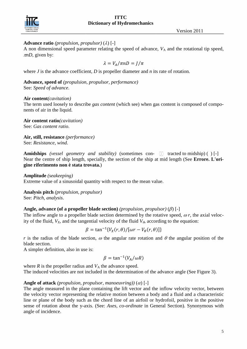
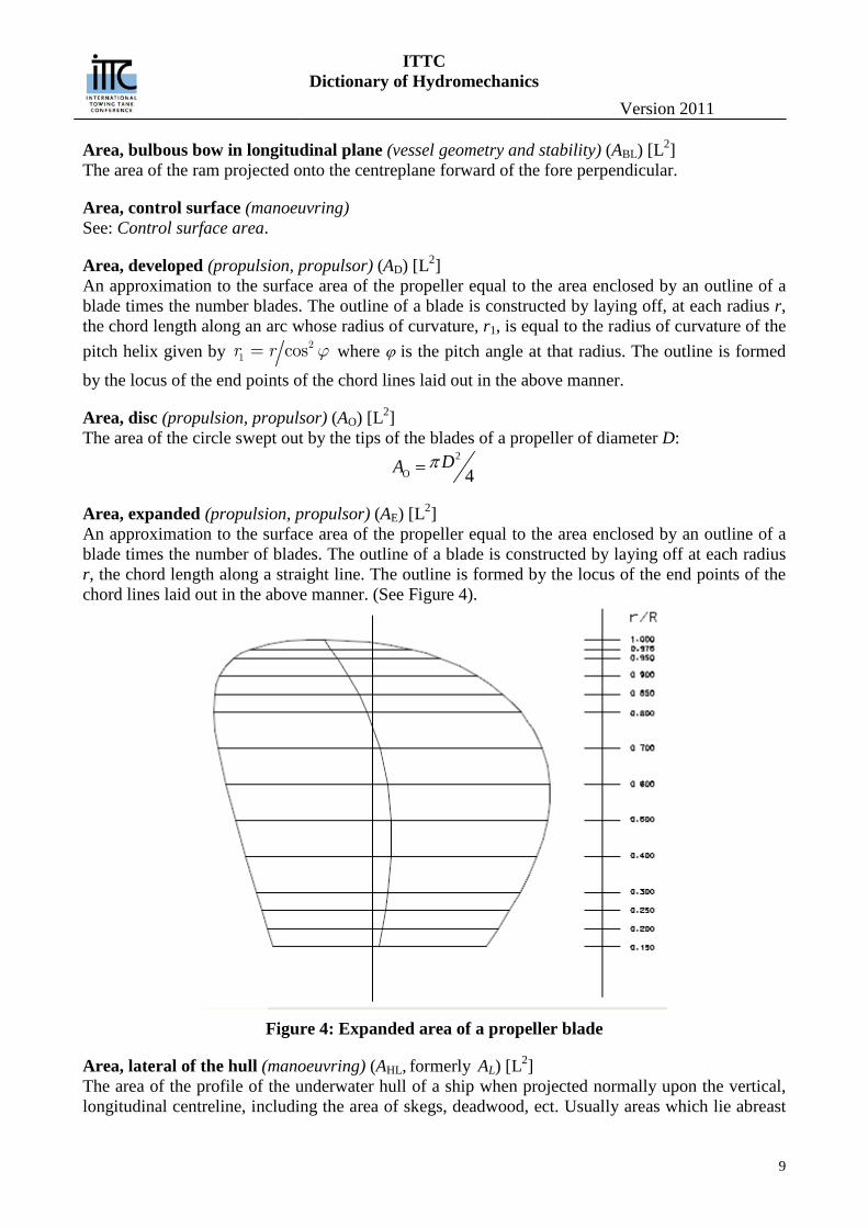
Area, expanded (propulsion, propulsor) (AE) [L2] An approximation to the surface area of the propeller equal to the area enclosed by an outline of a blade times the number of blades. The outline of a blade is constructed by laying off at each radius r, the chord length along a straight line. The outline is formed by the locus of the end points of the chord lines laid out in the above manner. (See Figure 4).
Figure 4: Expanded area of a propeller blade
Area, lateral of the hull (manoeuvring) (AHL, formerly AL) [L2] The area of the profile of the underwater hull of a ship when projected normally upon the vertical, longitudinal centreline, including the area of skegs, deadwood, ect. Usually areas which lie abreast
ITTC Dictionary of Hydromechanics
Version 2011
10
of one another, such as those of multiple skegs, are included once only. Lateral area can refer not only to the whole body, but also to forebody, afterbody, entrance, run, ect. Thus AHLF, AHLA, AHLE, AHLR, ect.
Area, maximum section (vessel geometry and stability) (AX) [L2] See: Section
Area, midship section, or midlenght section (vessel geometry and stability) (AM) [L2] See: Section
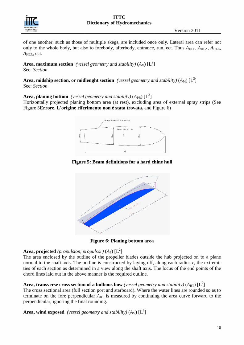
Area, planing bottom (vessel geometry and stability) (APB) [L2] Horizontally projected planing bottom area (at rest), excluding area of external spray strips (See Figure 5Errore. L'origine riferimento non è stata trovata. and Figure 6)
Figure 5: Beam definitions for a hard chine hull
Figure 6: Planing bottom area
Area, projected (propulsion, propulsor) (AP) [L2] The area enclosed by the outline of the propeller blades outside the hub projected on to a plane normal to the shaft axis. The outline is constructed by laying off, along each radius r, the extremi-ties of each section as determined in a view along the shaft axis. The locus of the end points of the chord lines laid out in the above manner is the required outline.
Area, transverse cross section of a bulbous bow (vessel geometry and stability) (ABT) [L2] The cross sectional area (full section port and starboard). Where the water lines are rounded so as to terminate on the fore perpendicular ABT is measured by continuing the area curve forward to the perpendicular, ignoring the final rounding.
Area, wind exposed (vessel geometry and stability) (AV) [L2]
ITTC Dictionary of Hydromechanics
Version 2011
11
Area of the portion of ship above the waterline projected to the direction of relative wind.
Aspect ratio (vessel geometry and stability manoeuvring) See: Ratio, aspect.
Attached cavities(cavitation) Term applied to cavitation region with fairly well defined line of attachment to the body about which it is formed. It may be a Fully developed cavity or Partial cavity (which see).
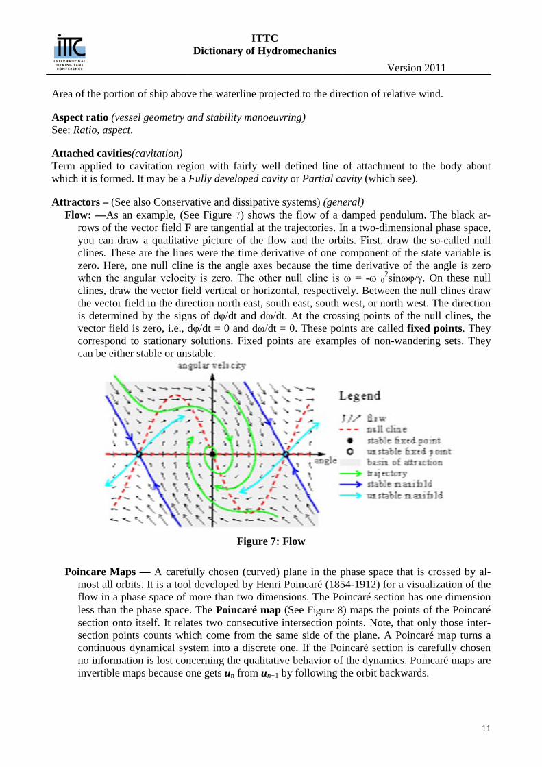
Attractors – (See also Conservative and dissipative systems) (general) Flow: —As an example, (See Figure 7) shows the flow of a damped pendulum. The black ar-
rows of the vector field F are tangential at the trajectories. In a two-dimensional phase space, you can draw a qualitative picture of the flow and the orbits. First, draw the so-called null clines. These are the lines were the time derivative of one component of the state variable is zero. Here, one null cline is the angle axes because the time derivative of the angle is zero when the angular velocity is zero. The other null cline is ω = -ω 0
2sinωφ/γ. On these null clines, draw the vector field vertical or horizontal, respectively. Between the null clines draw the vector field in the direction north east, south east, south west, or north west. The direction is determined by the signs of dφ/dt and dω/dt. At the crossing points of the null clines, the vector field is zero, i.e., dφ/dt = 0 and dω/dt = 0. These points are called fixed points. They correspond to stationary solutions. Fixed points are examples of non-wandering sets. They can be either stable or unstable.
Figure 7: Flow
Poincare Maps — A carefully chosen (curved) plane in the phase space that is crossed by al-
most all orbits. It is a tool developed by Henri Poincaré (1854-1912) for a visualization of the flow in a phase space of more than two dimensions. The Poincaré section has one dimension less than the phase space. The Poincaré map (See Figure 8) maps the points of the Poincaré section onto itself. It relates two consecutive intersection points. Note, that only those inter-section points counts which come from the same side of the plane. A Poincaré map turns a continuous dynamical system into a discrete one. If the Poincaré section is carefully chosen no information is lost concerning the qualitative behavior of the dynamics. Poincaré maps are invertible maps because one gets un from un+1 by following the orbit backwards.
ITTC Dictionary of Hydromechanics
Version 2011
12
Figure 8: Poincare Map
Chaotic orbits: — Bound non-periodic solutions. These solutions occur in driven pendula if the
driving is strong enough. The first three types can also occur in linear dynamics. The fourth type appears only in nonlinear systems. Its possibility was first anticipated by the genius of Henri Poincaré (1854-1912). In the meanwhile, computers had turned this previously counte-rintuitive behavior into a widespread experience. In the seventies, this irregular behavior was termed deterministic chaos. In the Poincaré map, limit cycles become fixed points. A non-wandering set can be either stable or unstable. Changing a parameter of the system can change the stability of a non-wandering set. This is accompanied by a change of the number of non-wandering sets due to a bifurcation.
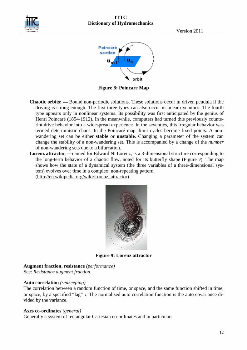
Lorenz attractor, —named for Edward N. Lorenz, is a 3-dimensional structure corresponding to the long-term behavior of a chaotic flow, noted for its butterfly shape (Figure 9). The map shows how the state of a dynamical system (the three variables of a three-dimensional sys-tem) evolves over time in a complex, non-repeating pattern. (http://en.wikipedia.org/wiki/Lorenz_attractor)
Figure 9: Lorenz attractor
Augment fraction, resistance (performance) See: Resistance augment fraction.
Auto correlation (seakeeping) The correlation between a random function of time, or space, and the same function shifted in time, or space, by a specified “lag” τ. The normalised auto correlation function is the auto covariance di-vided by the variance.
Axes co-ordinates (general) Generally a system of rectangular Cartesian co-ordinates and in particular:

ITTC Dictionary of Hydromechanics
Version 2011
13
Body axes (x, y, z) A right hand orthogonal system fixed in the body or ship. The x axis is for-ward and parallel to the reference or baseline used to define the body’s shape. For dynamic con-siderations the origin should be at the centre of the gravity of the body and the z axis vertically downwards. The y axis is to starboard. Fixed axes (x0, y0, z0). A right hand orthogonal system nominally fixed in relation to the earth; the positive z0 axis is vertically downwards and the x0 axis lies in the direction of initial motion.
Axial induced velocity (propulsion, propulsor) See: Induced velocity, axial.
ITTC Dictionary of Hydromechanics
Version 2011
14
B Back (of blade) (propulsion, propulsor) The side of a propeller blade which faces generally in the direction of ahead motion. This side of the blade is also known as the suction side of the blade because the average pressure there is lower then the pressure on the face of the blade during normal ahead operation. This side of the blade cor-responds to the upper surface of an airfoil or wing.
Back cavitation(cavitation) Cavitation occurring on the suction side (back) of a propeller blade.
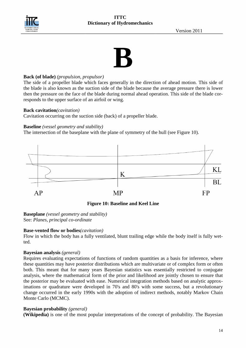
Baseline (vessel geometry and stability) The intersection of the baseplane with the plane of symmetry of the hull (see Figure 10).
Figure 10: Baseline and Keel Line
Baseplane (vessel geometry and stability) See: Planes, principal co-ordinate
Base-vented flow or bodies(cavitation) Flow in which the body has a fully ventilated, blunt trailing edge while the body itself is fully wet-ted.
Bayesian analysis (general) Requires evaluating expectations of functions of random quantities as a basis for inference, where these quantities may have posterior distributions which are multivariate or of complex form or often both. This meant that for many years Bayesian statistics was essentially restricted to conjugate analysis, where the mathematical form of the prior and likelihood are jointly chosen to ensure that the posterior may be evaluated with ease. Numerical integration methods based on analytic approx-imations or quadrature were developed in 70's and 80's with some success, but a revolutionary change occurred in the early 1990s with the adoption of indirect methods, notably Markov Chain Monte Carlo (MCMC).
Bayesian probability (general) (Wikipedia) is one of the most popular interpretations of the concept of probability. The Bayesian
ITTC Dictionary of Hydromechanics
Version 2011
15
interpretation of probability can be seen as an extension of logic that enables reasoning with uncer-tain statements. To evaluate the probability of a hypothesis, the Bayesian probabilist specifies some prior probability, which is then updated in the light of new relevant data. The Bayesian interpreta-tion provides a standard set of procedures and formulae to perform this calculation
Bayes' theorem Adjusts probabilities given new evidence in the following way:
where H is a hypothesis, and D is the data. P(H) is the prior probability of H: the probability that H is correct before the data D was seen. P(D | H) is the conditional probability of seeing the data D given that the hypothesis H is true.
P(D | H)is called the likelihood. P(D) is the marginal probability of D. P(H | D) is the posterior probability: the probability that the hypothesis is true, given the data
and the previous state of belief about the hypothesis. P(D) is the prior probability of witnessing the data D under all possible hypotheses. Given any
exhaustive set of mutually exclusive hypotheses Hi, we have:
We can consider i here to index alternative worlds, of which there is exactly one which we inhabit, and Hi is the hypothesis that we are in the world i. P(D, Hi) is then the probability that we are in the world i and witness the data. Since the set of alternative worlds was assumed to be mutually exclu-sive and exhaustive, the above formula is a case of the law of alternatives. P(D) is the normalizing constant, which in many cases need not be evaluated. As a result, Bayes' formula is often simplified to:
where ∝ denotes proportionality. In general, Bayesian methods are characterized by the following concepts and procedures: The use of hierarchical models, and the marginalization over the values of nuisance parameters.
In most cases, the computation is intractable, but good approximations can be obtained using Markov chain Monte Carlo methods.
The sequential use of the Bayes' formula: when more data becomes available after calculating a posterior distribution, the posterior becomes the next prior. Example: analysis of space launch failure rate as launches progress including analyzing near misses.
In frequentist statistics, a hypothesis is a proposition (which must be either true or false), so that the (frequentist) probability of a frequentist hypothesis is either one or zero. In Bayesian statis-tics, a probability H represents a specific hypothesis, which may or may not be some null hypo-thesis.
Beam ((vessel geometry and stability) B) [L] A dimension expressing breadth or width of a body or ship in a transverse horizontal direction. When not otherwise defined the beam is the breadth moulded of a ship, measured amidships at the design waterline. According to the position were the breadth is measured, it is named:
ITTC Dictionary of Hydromechanics
Version 2011
16
Beam, extreme: maximum beam wherever it occurs on the hull above or below water. Beam, immersed: maximum: maximum beam of underwater body Beam, maximum section (BX): beam measured on the designed waterline at the maximum sec-tion area. Beam, midlenght (BM): beam at the midsection of the designed waterline. Beam of design water line (BWL) [L]: maximum moulded breadth at design water line
For a hard chine hull the beam refers to the breadth or width of the planing bottom. According to the position were the breadth is measured, it is named:
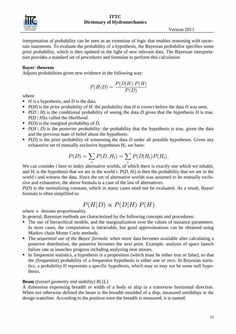
Beam, over chines (BPC) [L]: beam over chines, excluding external spray strips (See Figure 5). Beam, mean over chines (BPA) [L]: mean breadth over chines; defined as the ratio between planing bottom area and projected chine length (See Figure 11).
PBPA
PR
ABL
=
Beam, transom (BPT) [L]: Breadth over chines at transom, excluding external spray strips (See Figure 5). Beam, maximum over chines (BPX) [L]: Maximum breadth over chines, excluding external spray strips (See Figure 5).
Figure 11: Mean beam over chines
Bilge (vessel geometry and stability) The submerged transversally curved portion of the ship between the side and bottom. This region is also called the turn of the bilge. The minimum radius of the bilge at the section of maximum area is called bilge radius.
Bilge keel (vessel geometry and stability seakeeping) See: Keel
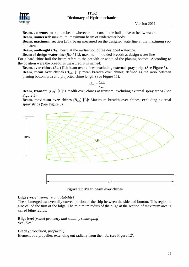
Blade (propulsion, propulsor) Element of a propeller, extending out radially from the hub. (see Figure 12).
ITTC Dictionary of Hydromechanics
Version 2011
17
Figure 12: Propeller Blade
Blade area ratio (propulsion, propulsor) [-] A term used to denote the ratio of either the developed or expanded area of the blades to the disc area. The terms expanded area ratio or developed area ratio are recommended in order to avoid am-biguity.
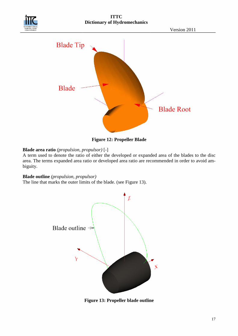
Blade outline (propulsion, propulsor) The line that marks the outer limits of the blade. (see Figure 13).
Figure 13: Propeller blade outline
ITTC Dictionary of Hydromechanics
Version 2011
18
Blade root (propulsion, propulsor) Zone of transition from blade to hub. . (see Figure 12).
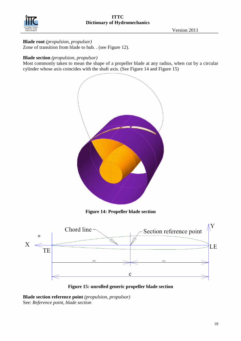
Blade section (propulsion, propulsor) Most commonly taken to mean the shape of a propeller blade at any radius, when cut by a circular cylinder whose axis coincides with the shaft axis. (See Figure 14 and Figure 15)
Figure 14: Propeller blade section
Figure 15: unrolled generic propeller blade section
Blade section reference point (propulsion, propulsor) See: Reference point, blade section
ITTC Dictionary of Hydromechanics
Version 2011
19
Blade thickness fraction (propulsion, propulsor) [-] If the maximum thickness of the propeller blade varies linearly with radius, then this variation of thickness may be imagined to extend to the axis of rotation. The hypothetical thickness at the axis of rotation, t0, divided by the diameter, is known as the blade thickness fraction or blade thickness ratio. If the thickness does not vary linearly with radius, then the blade thickness fraction is not uniquely defined.
Blade tip (propulsion, propulsor) Extreme part of the blade.) . (see Figure 12)..
Blockage (hydrodynamics) The effects of the boundaries of channel or tunnel on the flow around a body
Blockage correction (hydrodynamics) A correction made to the results of a hydrodynamic experiments made in a channel or tunnel of one cross-section in order to estimate the equivalent results for another cross-section. Specifically a cor-rection made to the results of a resistance experiment in a towing tank in other to estimate the equivalent results in unrestricted water.
Block coefficient (vessel geometry and stability) (CB, formerly δ) [-] The ratio of displacement volume ∇ to the volume of a rectangular block having length L, beam equal to the waterline beam BX an draught TX :
𝐶𝐵 =𝛻
𝐿𝐵𝑋𝑇𝑋
If it is referred to length, beam or draught other than those defined above, they should be clearly de-fined.
Body (vessel geometry and stability) Any hull or form which may be immersed or floating in a fluid, if a ship, usually its underwater por-tion. Particular parts of the body of a ship are:
Forebody: the part forward of the midsection Afterbody: the part aft of the midsection Parallel middle-body, length of, (LP) the midship portion having the same transverse section throughout. Entrance, length of, (LE): the portion extending from the maximum area section, or from the fore end of the parallel middle-body, to the forward extremity of the underwater body. Run, length of, (LR ): that portion extending from the maximum area section, or from the after end of the parallel middle-body, to the after extremity of the underwater body.
See Figure 47 for illustrations of these items.
Body plan (vessel geometry and stability) The transverse sections of the ship projected on to a vertical transverse plane. The sections are gen-erally equally spaced.
Bollard pull (propulsion, propulsor) [MTL-2] The pull force exerted by a ship at zero ship speed. It is the sum of the propeller thrust and the inter-action force on the hull.
ITTC Dictionary of Hydromechanics
Version 2011
20
Boundedness (general) is that property of a solution to a differential equation to remained bounded that is remain within a certain prescribed non-infinite value or not diverge beyond a certain value.
Safe Basin — that region in the phase space or Poincare map where solutions remain bounded
Boss (propulsion, propulsor) See: Hub.
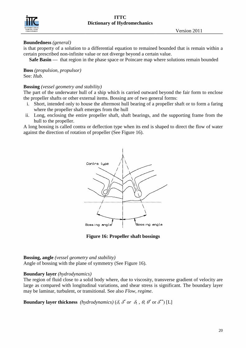
Bossing (vessel geometry and stability) The part of the underwater hull of a ship which is carried outward beyond the fair form to enclose the propeller shafts or other external items. Bossing are of two general forms:
i. Short, intended only to house the aftermost hull bearing of a propeller shaft or to form a faring where the propeller shaft emerges from the hull
ii. Long, enclosing the entire propeller shaft, shaft bearings, and the supporting frame from the hull to the propeller.
A long bossing is called contra or deflection type when its end is shaped to direct the flow of water against the direction of rotation of propeller (See Figure 16).
Figure 16: Propeller shaft bossings
Bossing, angle (vessel geometry and stability) Angle of bossing with the plane of symmetry (See Figure 16).
Boundary layer (hydrodynamics) The region of fluid close to a solid body where, due to viscosity, transverse gradient of velocity are large as compared with longitudinal variations, and shear stress is significant. The boundary layer may be laminar, turbulent, or transitional. See also Flow, regime.
Boundary layer thickness (hydrodynamics) (δ, δ∗ or δ1 , θ, θ∗ or δ∗∗) [L]
ITTC Dictionary of Hydromechanics
Version 2011
21
Boundary layer thickness (δ995): The distance normal to the surface of a body at which the speed attains that in an equivalent inviscid flow. For practical purposes this is sometimes taken as 99.5% of the inviscid flow speed or 99.5% of the total head . Displacement thickness (δ∗, δ1): the distance normal to the surface of a body by which stream-lines outside the boundary layer are displaced. For two-dimensional flow:
𝛿∗ = � �1 −𝑈�𝑈𝛿�
𝛿
𝑦=0𝑑𝑦
Where Uδ = the velocity at the edge of the boundary layer and U = velocity in the boundary layer. Momentum thickness (hydrodynamics) (θ): A parameter such that the quantity 𝜌𝑈02𝜃 is the defect in the rate transport of momentum due to the boundary layer. For two dimensional flow:
θ = �𝑈�𝑈𝛿
�1 −𝑈�𝑈𝛿�
𝛿
𝑦=0𝑑𝑦
Energy thickness (hydrodynamics) (θ∗, δ∗∗): A parameter such that quantity 12𝜌𝑈03𝜃 3 *1
2 0U is the defect in the rate of transport of kinetic energy due to the boundary layer. This is given by:
𝜃∗ = �𝑈�𝑈𝛿
�1 −𝑈²���
𝑈𝛿²�
𝛿
𝑦=0𝑑𝑦
Boundary plate (vessel geometry and stability) A plate at, or near, the tip of a hydrofoil, or of an element acting as a hydrofoil, to suppress or re-duce the tip vortex.
Bounded Rationality (general) (Mainzer, 2007 p334) — The capacity of the human mind for formulating and solving complex problems is very small compared with the size of the problem whose solution is required for objec-tively rational behavior in the real world or even for a reasonable approximation to such objective rationality
Bow (vessel geometry and stability) The forward end of a ship
Bowline (vessel geometry and stability) Intersection of a plane parallel to the centre plane with the moulded form of the forebody of the ship, both above and below the waterline. Similar intersections in the afterbody are called buttocks.
Brake power (performance) See: Power, brake.
Breadth (vessel geometry and stability) A length dimension expressing beam or width. (See: beam)
Breadth coefficient of, R.E: Froude (vessel geometry and stability) (BC) [-] The ratio of the maximum breadth to the cube root of the volume displacement of a ship.
ITTC Dictionary of Hydromechanics
Version 2011
22
𝐵C =𝐵𝑋𝛻1 3�
in a consistent system of units.
Breakwater (vessel geometry and stability) A protection erected on the weather deck, generally forward, normally V-shape in planform, to pre-vent water shipped over the bow from running aft.
Broaching (seakeeping) — An involuntary and dangerous change of heading produced by a severe following or quartering sea. — (MCA) A severe, and often uncontrollable, yawing movement in following seas which turns the vessel beam on to the waves resulting in a dangerously heavy roll, and a sideways sliding motion down-sea. In monohulls with insufficient stability it can result in capsize. It maybe preceded by surfing. — A type of ship directional instability which is characterized by a sudden large yaw from the orig-inal heading. A broach can arise in following and stern-quartering seas and may manifest itself in a number of ways:
Broaching Caused by a Single Wave — Usually the result of one or a number of motions that includes surf riding or bow submergence and coupled pitch, roll and yaw instability at high speed. All are possible in following or stern-quartering seas.
Bubble collapse(cavitation) The final phase in the life history of a transient cavitation bubble that enters an increasing pressure field collapses and, unless containing considerable foreign gas, disappears. The total life of a tran-sient cavitation bubble is measured in times of the order of milliseconds,
Bubble growth(cavitation) The initial phase in the life history of a cavitation bubble in which a nucleus become unstable under a pressure reduction and grows explosively (vaporous cavitation) or which grows under quasi-equilibrium conditions by diffusion of gas (gaseous cavitation).
Bubble rebound(cavitation) Regrowth, after initial collapse, of a transient cavity that contains considerable permanent gas, due to energy storage in the compressed gas. Several growth and rebound cycles have sometimes been observed.
Bubble surface stability(cavitation) The stability of the bubble surface. Expanding bubbles are stable. Collapsing bubbles are unstable, being subject to Taylor instability (light fluid accelerated toward a heavier fluid) or distortions pro-duced by body forces in a pressure gradient.
Bulb (vessel geometry and stability) An appreciable swelling of the ship form generally below the waterline, involving increase of sec-tion area; frequently at the forward end lying just above the keel (bulbous bow), sometimes with in-crease of length beyond the forward perpendicular (ram bulb), sometimes the after end near the keel or at the level of the propeller shaft (stern bulb). The ram bulb dimensions are characterised by the transverse cross section area at the fore perpendicular (ABT), and the ram area in the longitudinal
ITTC Dictionary of Hydromechanics
Version 2011
23
plane (ABL), which is the area of ram ahead of the fore perpendicular projected on to the centre plane. In non dimensional form:
Taylor sectional area coefficient for bulbous bow (vessel geometry and stability) (fBT) [-] :
BTBT
X
Af
A
Area coefficient for ram bow (vessel geometry and stability) (fBL) [-]:
BLBL
Af
LT
When the waterlines are rounded so as to terminate on the forward perpendicular, ABT is measured by continuing the area curve forward to the perpendicular, ignoring the final rounding. In some in-stances, the stem contour recedes aft the fore perpendicular below the load waterline before project-ing forward to define the outline of the ram or fore end of the bulb. In such instances this area should be calculated using as datum the aftermost vertical tangent to the contour instead of the fore perpendicular.
Buoyant Volume (vessel geometry and stability) The watertight volume of a vessel
Note: USCG NVIC 5-86: — Deckhouses should be included in the buoyant volume only if: a. They are of substantial construction so that they can withstand the impact forces of waves, b. They have internal access to the spaces below; otherwise it should be assumed that the exte-rior doors will be used for access, thus disrupting the buoyant envelope watertight integrity. c. All openings in the sides of the deckhouse are weathertight. (NOTE: Joiner doors should not be considered as weathertight.), d. All windows have deadlight covers. In general, volumes which are watertight and of sufficient strength are fully effective. The Coast Guard recommends that all fully effective volumes be in-cluded in the buoyant volume for the righting arm calculations. Although the exclusion of these volumes may be more conservative, using the allowed buoyant volumes permits a more accurate assessment of the vessel's stability characteristics.
Buttok (vessel geometry and stability) The intersection of a plane parallel to the centreplane with the moulded form of the ship, both below and above the waterplane. Specifically, all such intersections in the afterbody, as distinguished from similar intersections in the forebody, called bowlines.
ITTC Dictionary of Hydromechanics
Version 2011
24
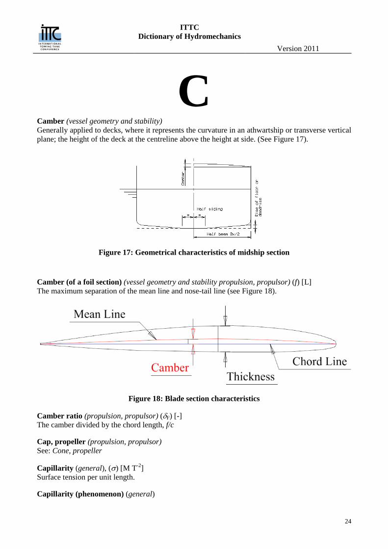
C Camber (vessel geometry and stability) Generally applied to decks, where it represents the curvature in an athwartship or transverse vertical plane; the height of the deck at the centreline above the height at side. (See Figure 17).
Figure 17: Geometrical characteristics of midship section
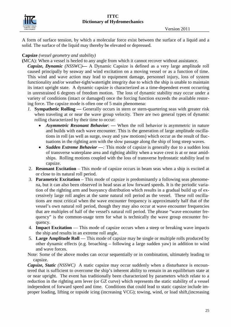
Camber (of a foil section) (vessel geometry and stability propulsion, propulsor) (f) [L] The maximum separation of the mean line and nose-tail line (see Figure 18).
Figure 18: Blade section characteristics
Camber ratio (propulsion, propulsor) (δF) [-] The camber divided by the chord length, f/c
Cap, propeller (propulsion, propulsor) See: Cone, propeller
Capillarity (general), (σ) [M T-2] Surface tension per unit length.
Capillarity (phenomenon) (general)
ITTC Dictionary of Hydromechanics
Version 2011
25
A form of surface tension, by which a molecular force exist between the surface of a liquid and a solid. The surface of the liquid may thereby be elevated or depressed.
Capsize (vessel geometry and stability) (MCA): When a vessel is heeled to any angle from which it cannot recover without assistance.
Capsize, Dynamic (NSSWC)— A Dynamic Capsize is defined as a very large amplitude roll caused principally by seaway and wind excitation on a moving vessel or as a function of time. This wind and wave action may lead to equipment damage, personnel injury, loss of system functionality and/or weather-tight/watertight integrity due to which the ship is unable to maintain its intact upright state. A dynamic capsize is characterized as a time-dependent event occurring in unrestrained 6 degrees of freedom motion. The loss of dynamic stability may occur under a variety of conditions (intact or damaged) once the forcing function exceeds the available restor-ing force. The capsize mode is often one of 5 main phenomena: 1. Sympathetic Rolling — Generally occurs in stern or stern-quartering seas with greater risk
when traveling at or near the wave group velocity. There are two general types of dynamic rolling characterized by their time to occur:
• Asymmetric Resonant Behavior: — When the roll behavior is asymmetric in nature and builds with each wave encounter. This is the generation of large amplitude oscilla-tions in roll (as well as surge, sway and yaw motions) which occur as the result of fluc-tuations in the righting arm with the slow passage along the ship of long steep waves.
• Sudden Extreme Behavior —: This mode of capsize is generally due to a sudden loss of transverse waterplane area and righting ability when a wave crest is at or near amid-ships. Rolling motions coupled with the loss of transverse hydrostatic stability lead to capsize.
2. Resonant Excitation – This mode of capsize occurs in beam seas when a ship is excited at or close to its natural roll period.
3. Parametric Excitation – This mode of capsize is predominantly a following seas phenome-na, but it can also been observed in head seas at low forward speeds. It is the periodic varia-tion of the righting arm and buoyancy distribution which results in a gradual build up of ex-cessively large roll angles at the same natural roll period as the vessel. These roll oscilla-tions are most critical when the wave encounter frequency is approximately half that of the vessel’s own natural roll period, though they may also occur at wave encounter frequencies that are multiples of half of the vessel's natural roll period. The phrase “wave encounter fre-quency” is the common-usage term for what is technically the wave group encounter fre-quency.
4. Impact Excitation — This mode of capsize occurs when a steep or breaking wave impacts the ship and results in an extreme roll angle.
5. Large Amplitude Roll — This mode of capsize may be single or multiple rolls produced by other dynamic effects (e.g. broaching – following a large sudden yaw) in addition to wind and wave forces.
Note: Some of the above modes can occur sequentially or in combination, ultimately leading to capsize.
Capsize, Static (NSSWC) A static capsize may occur suddenly when a disturbance is encoun-tered that is sufficient to overcome the ship’s inherent ability to remain in an equilibrium state at or near upright. The event has traditionally been characterized by parameters which relate to a reduction in the righting arm lever (or GZ curve) which represents the static stability of a vessel independent of forward speed and time. Conditions that could lead to static capsize include im-proper loading, lifting or topside icing (increasing VCG); towing, wind, or load shift,(increasing
ITTC Dictionary of Hydromechanics
Version 2011
26
heel angle); trapped fluids on deck (increasing free surface effects); and loss of watertight integr-ity (loss of buoyancy/waterplane area).
Cascade Failure (general) A failure in a system of interconnected parts in which the failure of a part can trigger the failure of successive parts. They occur in power system grids, computer networks, vessel capsizes involving impaired stability. System failure in non-concurrency mode is capable of prevention by human in-tervention such as the USCG delivering a dewatering pump to a fishing vessel taking on water. In finance systems, where the risk of cascading failures of financial institutions is referred to as sys-temic risk: the failure of one financial institution may cause other financial institutions (its counter-parties) to fail, cascading throughout the system. Institutions that are believed to pose systemic risk are deemed either "too big to fail" (TBTF)
Cavitating flow(cavitation) A two-phase flow composed of a liquid and its vapour is called a cavitating flow when the phase transition is a result of a hydrodynamic pressure change.
Cavitating wakes(cavitation) Cavitation that occurs in the low pressure cores of the turbulent eddies which make up the wake of a moving body.
Cavitation (cavitation) In the most engineering contexts, cavitation is defined as the process of formation of the vapour phase of a liquid when it is subjected to reduced pressure at constant ambient temperature. In gen-eral, a liquid is said to cavitate when vapour bubbles are observed to from and grow as a conse-quence of pressure reduction. (See also: Vaporous cavitation and Gaseous cavitation).
Cavitation damage(cavitation) Deformation and/or erosion of materials in cavitated regions, associated primarily with the high pressures developed during cavity collapse.
Cavitation inception(cavitation) Inception of cavitation takes place when nuclei subjected to reduced pressure reach critical size and grow explosively. It is generally described by the ambient pressure at which cavitation starts, or more precisely, by the Critical cavitation number (which see).
Cavitation number (cavitation) (σ) [-] The ratio of the difference between absolute ambient pressure p and cavity pressure pC to the free stream dynamic pressure q:
𝜎 =𝑝 − 𝑝C𝑞
When the cavity pressure is assumed to be the vapour pressure pV the term is generally called Va-pour cavitation number (which see as Cavitation number, vapour).
Cavitation number, critical (cavitation) Often used as an alternate to Inception cavitation number (which see as Cavitation number, incep-tion).
ITTC Dictionary of Hydromechanics
Version 2011
27
Cavitation number, inception (σI) [-] (cavitation) The inception cavitation number σI is the value of the cavitation number σ at which the inception of cavitation occurs in a flowing system. When σI > σ, cavitation will not occur; thus σI is the char-acteristic of the flow geometry while σ is characteristic of the liquid gas system. (In practical sys-tem, the definition of σ is usually based on the vapour pressure.) Sometimes also called Critical cavitation number (which see as Cavitation number, critical).
Cavitation number, vapour (σV) [-] (cavitation) The ratio of the difference between absolute ambient pressure p and vapour pressure pV to the free stream dynamic pressure q:
𝜎V =𝑝 − 𝑝V𝑞
See also: Cavitation number.
Cavity drag (cavitation) (DC) [LMT-2] The energy expended in forming a fully-developed cavity, which cannot be recovered at cavity clo-sure and hence is exhibited as drag on the body. It is equal to the energy in the re-entrant jet which is dissipated.
Cavity length (cavitation) (lC) [L] The streamwise dimension of a fully developed cavitating region, extending from its leading edge (point of attachment) to the point of closure.
Cavity pressure (cavitation) (pC) [L-1MT-2] Actual pressure within a steady (or quasi-steady) cavity. Approximately equal to the sum of the par-tial pressure of vapour and other gases diffused and entrained into the cavity.
Cavity thickness (cavitation) (δC) [L] Maximum dimension of a fully developed cavity normal to the length dimension.
Celerity (seakeeping) See: Wave speed.
Central Limit Theorem (general) States that the sum of a large number of independent and identically-distributed random variables will be approximately normally distributed (i.e., following a Gaussian distribution, or bell-shaped curve) if the random variables have a finite variance. Formally, a central limit theorem is any of a set of weak-convergence results in probability theory. They all express the fact that any sum of many independent identically distributed random variables will tend to be distributed according to a particular "attractor distribution".
Centre of buoyancy (vessel geometry and stability) (B) [-] The geometric centroid, B of the submerged volume of a body or ship through which the total buoy-ancy may be assumed to act. Its position, measured as the distance from midship or from the fore (FB ) or after perpendicular (AB ) is called the Longitudinal centre of buoyancy and from the base line or keel (KB ) the Vertical centre of buoyancy. In non dimensional form these distances are of-ten expressed as ratios of length of the ship FB
L or ABL , and of the draught KB
T respectively.
ITTC Dictionary of Hydromechanics
Version 2011
28
Centre of flotation (vessel geometry and stability) (F) [-] The geometric centroid of the area of waterplane of any waterline. Its position measured as the dis-tance from midships or from the fore or after perpendicular, is called Longitudinal centre of flota-tion, and is generally expressed as a ratio of the waterline length.
Centre of gravity (vessel geometry and stability) (G) [-] The centre through which all the weights constituting the ship and its contents may be assumed to act. The distance measured from midships, from the fore perpendicular (FG ) or from the after per-pendicular (AG ), and from the baseline or keel (KG ) are called Longitudinal and Vertical centre of gravity respectively. They are generally expressed as ratios of the ship length FG
L or AGL
and of the ship depth KGD respectively.
Centre of lateral area (manoeuvring) The centre of the lateral area of the immersed portion of a ship or body, taken generally in the plane of symmetry.
Centre of lateral force (manoeuvring) The point in the plane of symmetry through which the resultant force would act to produce an effect equal to that of the total lateral hydrodynamic force on a vessel.
Centreplane (vessel geometry and stability) See: Planes, principal, co-ordinate.
Centrifugal spindle torque (propulsion, propulsor) See: Spindle torque, centrifugal Chaotic system (general) A deterministic but non-linear dynamical system which produces multiple outputs for a given set of initial conditions.
Chemo-luminescence (cavitation) Visible light produced in the gas vapour of cavities in an ultrasonic field (see: Sono-luminescence) caused by chemical reactions associated with high pressure and/or temperatures.
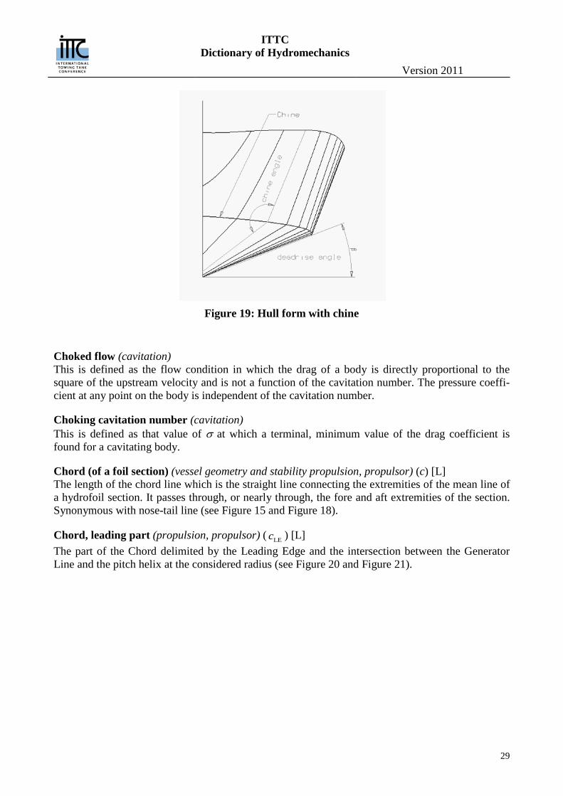
Chine (vessel geometry and stability) (See Figure 19) A more or less sharp corner or knuckle in the hull form, continuous over a significant length of the ship, as in the junction of side and bottom in planing craft. The chine is known as “soft” when the corner is rounded, and “hard” otherwise.
Chine angle (vessel geometry and stability) (See Figure 19) The angle at the junction between the two parts of a section, on either side of a chine or the angle between the tangents to these two parts, measured in a transverse plane.
Chine line (vessel geometry and stability) (See Figure 19) The actual (in a “hard” chine), or imaginary (in a “soft” chine), locus of the intersections of the two parts of the hull form at the chine.
ITTC Dictionary of Hydromechanics
Version 2011
29
Figure 19: Hull form with chine
Choked flow (cavitation) This is defined as the flow condition in which the drag of a body is directly proportional to the square of the upstream velocity and is not a function of the cavitation number. The pressure coeffi-cient at any point on the body is independent of the cavitation number.
Choking cavitation number (cavitation) This is defined as that value of σ at which a terminal, minimum value of the drag coefficient is found for a cavitating body.
Chord (of a foil section) (vessel geometry and stability propulsion, propulsor) (c) [L] The length of the chord line which is the straight line connecting the extremities of the mean line of a hydrofoil section. It passes through, or nearly through, the fore and aft extremities of the section. Synonymous with nose-tail line (see Figure 15 and Figure 18).
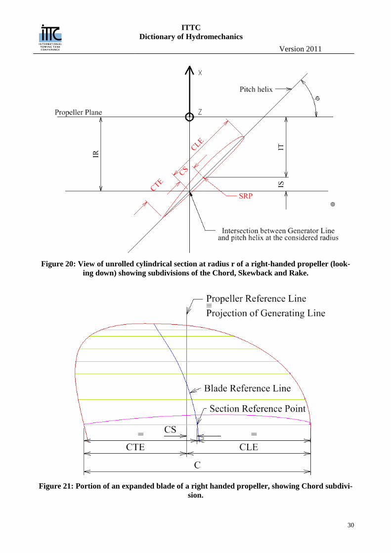
Chord, leading part (propulsion, propulsor) ( LEc ) [L] The part of the Chord delimited by the Leading Edge and the intersection between the Generator Line and the pitch helix at the considered radius (see Figure 20 and Figure 21).
ITTC Dictionary of Hydromechanics
Version 2011
30
Figure 20: View of unrolled cylindrical section at radius r of a right-handed propeller (look-
ing down) showing subdivisions of the Chord, Skewback and Rake.
Figure 21: Portion of an expanded blade of a right handed propeller, showing Chord subdivi-
sion.
ITTC Dictionary of Hydromechanics
Version 2011
31
Chord, trailing part (propulsion, propulsor) ( TEc ) [L] The part of the Chord delimited by the Trailing Edge and the intersection between the Generator Line and the pitch helix at the considered radius (see Figure 20 and Figure 21).
Chord length, mean (propulsion, propulsor) ( Mc ) [L] The quotient obtained by dividing the expanded or developed area of a propeller blade by the span from the hub to the tip.
Chord line (propulsion, propulsor) The straight line connecting the extremities of the mean line. The length of this line is called the chord length or simply the chord. It passes through, or nearly through, the fore and aft extremities of the section. Synonymous with nose-tail line (see Figure 15 and Figure 18).
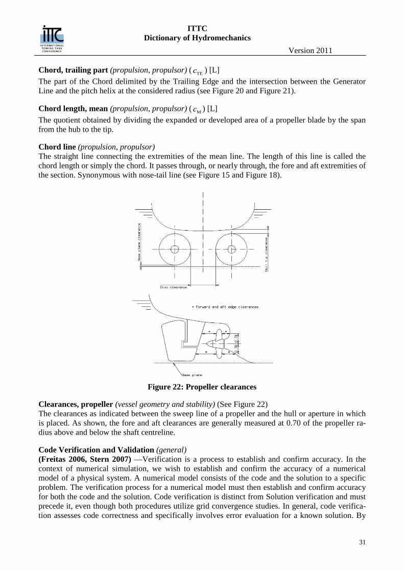
Figure 22: Propeller clearances
Clearances, propeller (vessel geometry and stability) (See Figure 22) The clearances as indicated between the sweep line of a propeller and the hull or aperture in which is placed. As shown, the fore and aft clearances are generally measured at 0.70 of the propeller ra-dius above and below the shaft centreline.
Code Verification and Validation (general) (Freitas 2006, Stern 2007) —Verification is a process to establish and confirm accuracy. In the context of numerical simulation, we wish to establish and confirm the accuracy of a numerical model of a physical system. A numerical model consists of the code and the solution to a specific problem. The verification process for a numerical model must then establish and confirm accuracy for both the code and the solution. Code verification is distinct from Solution verification and must precede it, even though both procedures utilize grid convergence studies. In general, code verifica-tion assesses code correctness and specifically involves error evaluation for a known solution. By
ITTC Dictionary of Hydromechanics
Version 2011
32
contrast, solution verification involves error estimation, since we do not know the exact solution to the specific problem. Code and solution verification are mathematical activities, with no concern whatever for the agreement of the numerical model with physical data from experiments, that is the concern of validation. Note, however, that the solution and its error estimation from solution verifi-cation will be used in the validation process. In this way, code verification, solution verification, and validation are coupled together into an overall process
Coefficient, Admiralty (performance) See: Admiralty coefficient.
Coefficient, block (vessel geometry and stability) See: Block coefficient.
Coefficient of lateral area (manoeuvring) (CAL, formerly CLA) [-] The ratio of the lateral area of the bare hull of a ship to the area of a rectangle having the ship length L and a constant depth equal to draft TX at the station of maximum area.
Coefficient, prismatic (vessel geometry and stability) See: Prismatic coefficient.
Coefficient, prismatic, vertical (vessel geometry and stability) See: Prismatic coefficient, vertical.
Coefficient, quasi-propulsive (performance) See: Efficiency, propulsive, and Efficiency, quasi-propulsive.
Coefficient, maximum transverse and midship section (vessel geometry and stability) See: Sectional area coefficient.
Coefficient, waterplane, designed load (vessel geometry and stability) See: Waterplane coefficient, designed load.
Coefficient, waterplane, inertia (vessel geometry and stability) See: Waterplane inertia coefficient.
Coefficient, wind resistance (performance) See: Resistance coefficient, wind.
Coherency (seakeeping) A measured of the linear dependency of two random functions of time, or space, analogous to a cor-relation coefficient.
Collapse pressure (cavitation) (pAC) [L-1MT-2] The pressure produced in the field of a collapsing cavitation bubble estimated to be of the order of thousands of atmospheres at the minimum radius reached before the process stops or rebound be-gins. Common cause Failure (general) Defined as a specific condition which may result in a single failure event and which would be capa-ble of causing each element of channel of a redundant system to fail.
ITTC Dictionary of Hydromechanics
Version 2011
33
Critical period —:Multiple failures though common cause of elements of a redundant system will result in overall systems failure if they occur within a time interval known as the critical pe-riod. Non-concurrency —: When multiple failures through common cause of elements of a redundant system occur over a give time interval greater than the critical period, the individual element are said to be non-concurrent. System failure in non-concurrency mode is capable of prevention by human intervention or scheduled changes in process operation. (Mediation)
Common Mode Failures (general) In technical facilities, for example in nuclear power plants and commercial aircraft, redundant sys-tems are used to prevent random failures from deleting the complete system function. However, al-though this redundancy concept is adequate to cope with random failures in single redundancies, its applicability is limited in case of multiple failures due to a systematic failure cause to which all re-dundancies are submitted due to their identical features. Some general considerations have been formulated to rule out the occurrence of such common mode failure (CMF) in redundant systems under certain circumstances. CMF means that in more than one redundancy the systematic failure cause is activated at the same time, or within the same frame of time (e.g. during the mission time for an accident)
Complex System (general) (Wikipedia) A system composed of interconnected parts that as a whole exhibit one or more prop-erties (behavior among the possible properties) not obvious from the properties of the individual parts. A system’s complexity may be of one of two forms: disorganized complexity and organized complexity. In essence, disorganized complexity is a matter of a very large number of parts, and or-ganized complexity is a matter of the subject system (quite possibly with only a limited number of parts) exhibiting emergent properties.
Complex Systems (general) (CS) — A category that includes most physical systems beyond the simple category such as human-conceived production systems, weather models, various economic systems, and models and simula-tions of real dynamic systems whose behavior depends on a complex set of rules and constraints. Complex Systems can be either deterministic or non-deterministic (probabilistic) or a combination of both. The nature of the forcing functions impacts on this distinction.
Complex Adaptive Systems (CAS) — are special cases of complex systems. They are complex in that they are diverse and made up of multiple interconnected elements and adaptive in that they have the capacity to change and learn from experience. — Include intelligent systems and rule-based simulations that self-organize by learning and/or adapting to new classifier (pattern recog-nition) rules.
Compressibility, coefficient of (general), ( - ) [LM-1 T2 ] The reciprocal of the volume or bulk modulus of elasticity. (See: Modulus of elasticity, volume or bulk)
Conditional probability (general) Is the probability of some event A, given the occurrence of some other event B. Conditional proba-bility is written P(A|B), and is read "the probability of A, given B".
Conditioning (general)
ITTC Dictionary of Hydromechanics
Version 2011
34
of probabilities, i.e. updating them to take account of (possibly new) information, may be achieved through Bayes' theorem. In such conditioning, the probability of A given only initial information I, P(A|I), is known as the prior probability. The updated conditional probability of A, given I and the outcome of the event B, is known as the posterior probability, P(A|B,I).
Cone, propeller (propulsion, propulsor) The conical-shaped cover placed over the after end of the propeller shaft for the purpose of protect-ing the nut and forming a hydrodynamic fairing for the hub. Also known as a propeller fairwater or a propeller cap.
Confidence interval (general) A range that contains the true value of mean value, variance, or any other probabilistic characteristic, with a given confidence probability β
Conservative and Dissipative systems (general) (Mainzer, 2007)—Since Poincaré’s celestial mechanics (1892), it was mathematically known that some mechanical systems whose time evolution is governed by nonlinear Hamiltonian equations could display chaotic motion involving vortex points in the phase plane. Mathematically, nonli-nearity is a necessary, but not sufficient condition of chaos. It is a necessary condition, because linear differential equations can be solved by well-known mathematical procedures (Fourier trans-formations) and do not lead to chaos. The system Lorenz used to model the dynamics of weather differs from Hamiltonian systems a la Poincaré mainly by its dissipativity (irreversible entropy generation and mathematical spiraling point attractors) Roughly speaking, a mathematical de-scription of a dissipative system involving friction is not conservative but open with an external control parameter that can be tuned to critical values causing the transitions to chaos, i.e. a ther-modynamically open system which is operating far from thermodynamic equilibrium in an envi-ronment with which it exchanges energy and matter
Constitutive Equation (general) (See Noll, 1974) — An equation relating the stress tensor in Cauchy’s Field Equations of Motion to the deformation rate tensor for both Newtonian and non-Newtonian fluids. To eliminate the shear stress component leaving only normal stresses (pressure) in the Euler Equations of Motion, the fluid is assumed to in inviscid, making the solutions time reversible (isentropic). Assuming viscous flow makes the solution irreversible and entropy generating. The Navier Stokes equations assume the shear stresses are linearly related to the combination of deformation rate and turbulent Reynold’s stresses
Construct Validity (general) Addresses the degree to which the results of the method can be accounted for by the explanatory constructs of a sound theory. A method's construct validity can be assessed by specifying the theo-retical relationships between the concepts and then examining the empirical relationships between the measures of the concepts, and then interpreting how the observed evidence clarifies the concepts being addressed. Construct validity is demonstrated when measures that are theoretically predicted to be highly interrelated are shown in practice to be highly interrelated.
Content Validity (general) Addresses the degree to which the method addresses the problem (issue) it is intended to address.
Contrarotating propeller (propulsion, propulsor)
ITTC Dictionary of Hydromechanics
Version 2011
35
See: Propeller Types.
Control (general), As a noun, is applied to the act o controlling or directing, such as when controlling the movements of body or directing a ship in the steering, turning, and diving manoeuvres.
Control devices (manoeuvring) Control devices comprise all the various devices that are used to control a body or ship, such as control surfaces, thruster, jets, ect.
Control surfaces (general, manoeuvring) Control surfaces are the rudders, hydroplanes and other hinged or movable devices used for control-ling the motion of a body or ship.
Control surface area (manoeuvring) ( AFB, AFS, AR, ect) [L2] The plan form area of any active or movable control surface, such as that of bow fins AFB, stern fins AFB or rudder AR, measured on the reference plane (generally the plane of symmetry). See also: Rudder area.
Control surface angle (manoeuvring) (δFB, δR ect) [-] The angular displacement of any control surface about its hinge or stock, such as that of a bow fin δFB, or rudder δR. Positive when turning in the positive sense of rotation of the ship, regardless of the effect this angle may have on the ship. See also: Rudder angle.
Controllability (general) That quality of a body or ship which determines the effectiveness of movement of the controls in the producing any desire change, at a specified rate in the attitude or position of the moving body or ship
Controls (general) The means or system provided to enable the crew of a ship to control its speed, power, attitude, di-rection of motion, and the like.
Correlation allowance, model-ship (performance) (RA) [LMT-2] This is the addition which has to be made to the resistance of the “smooth” ship, as predicted from the model results, to bring it into agreement with the actual ship performance determined from full scale trial or service result. The correlation allowance depends upon the method used to extrapolate the model results to the “smooth” ship, the ship length and type, the basic shell roughness of the newly-painted ship, fouling, weather conditions at the time the ship measurements were taken and scale effects on the factor making up the model and ship propulsive coefficients.
Correlation allowance coefficient (performance) See: Resistance coefficient, incremental, for model-ship correlation.
Correlation factor, ship-model, for propeller rate of evolution (performance) (K2) [-] The scale effect between the rate of propeller rotation of model nM and ship nS is defined by the fac-tor K2, such that
𝐾2 =𝑛S𝑛M
√𝜆
ITTC Dictionary of Hydromechanics
Version 2011
36
where λ is the scale factor.
Correlation factor, ship-model, for propulsive or quasi-propulsive efficiency (performance) (K1) [-] The scale effect between the propulsive efficiencies of the model and ship is defined by the factor K1, such that
𝐾1 =𝜂DS𝜂DM
where the efficiencies ηDS and ηDM for ship and model respectively are derived at corresponding speed and propeller loading.
Counter (vessel geometry and stability) The overhanging portion of stern of a ship which lies between the designed waterplane and deck and which project abaft the waterline termination. See also Stern, Counter or Fantail and Figure 55 a).
Coupling (general) (seakeeping) Influence of one mode of motion on another mode of motion, for instance, coupling between heave and pitch.
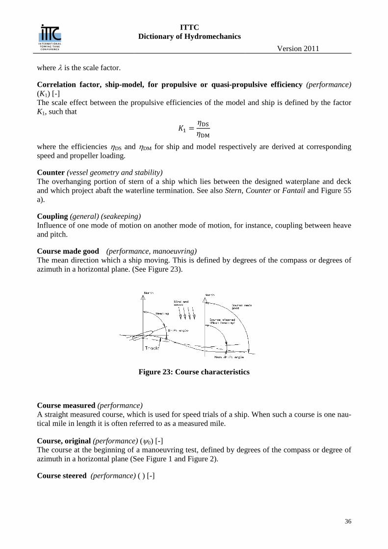
Course made good (performance, manoeuvring) The mean direction which a ship moving. This is defined by degrees of the compass or degrees of azimuth in a horizontal plane. (See Figure 23).
Figure 23: Course characteristics
Course measured (performance) A straight measured course, which is used for speed trials of a ship. When such a course is one nau-tical mile in length it is often referred to as a measured mile.
Course, original (performance) (ψ0) [-] The course at the beginning of a manoeuvring test, defined by degrees of the compass or degree of azimuth in a horizontal plane (See Figure 1 and Figure 2).
Course steered (performance) ( ) [-]
ITTC Dictionary of Hydromechanics
Version 2011
37
The mean heading of a ship, defined by degrees of the compass or degrees of azimuth in a horizon-tal plane. (See Figure 52). (manoeuvring) (ψO) [-] The mean heading of a ship, defined by degrees of the compass or degree of azimuth in a horizontal plane (See Figure 52).
Covariance (seakeeping) Average of squares of the deviations from the mean value.
Crash-back , Crash Stop (manoeuvring) A ship manoeuvre in which, while going ahead at normal or some other speed, the propulsion de-vices are reversed in the shortest possible time.
Criterion Validity (general) Addresses the degree to which the method allows for assessment of an issue or problem beyond the testing situation; the generalizability of the method. Criterion validity may be concurrent or predic-tive; the evaluation may be either be intended to assess a criterion independently evaluated at the same time (concurrent), or to predict achieving a criterion in the future (predictive).
Critical cavitation number (cavitation) See: Cavitation number critical.
Critical pressure (cavitation) (pAI) [L-1MT-2] The absolute pressure at which cavitation inception takes place, in either a flowing system or an imposed pressure field (as in ultrasonic cavitation). In turbulent flow, the critical pressure will be a function of the average hydrodynamic pressure and the pressure fluctuations associated with turbu-lence. Sometimes also called Inception pressure. (See also: Gaseous and Vaporous cavitation.)
Critical velocity (cavitation) (UI) [LT-1] In a flowing system (or its equivalent: a body moving through a liquid), the free stream velocity at which cavitation inception takes place in a field of constant ambient pressure. In a turbulent flow, the critical velocity is also dependent on the velocity fluctuations associated with turbulence. Some-times also called Inception velocity.
Cross-correlation (seakeeping) The correlation between two random functions of time, or pace, with one shifted in relation to the other by a “lag” τ.
Cross force (manoeuvring) (C ) See: Force, cross
Cross force coefficient (manoeuvring) (CC) [-] The ratio of the cross force C on a ship or body to the force corresponding to the dynamic pressure times a specified area. It is customary to expressed it as CC C qA .
Current, tidal (performance) A current in the water caused by the tide and influenced by the coastline and contours of the seabed.
Current, wind (performance)
ITTC Dictionary of Hydromechanics
Version 2011
38
A surface or near-surface current in a body of water induced by wind.
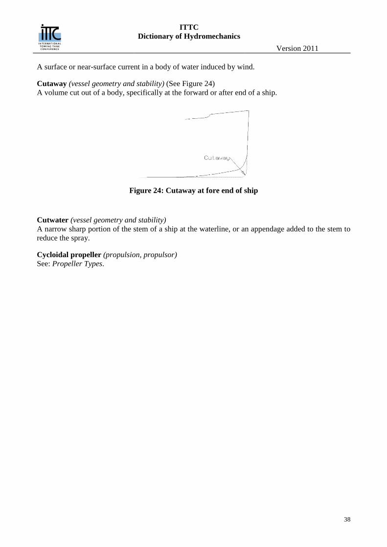
Cutaway (vessel geometry and stability) (See Figure 24) A volume cut out of a body, specifically at the forward or after end of a ship.
Figure 24: Cutaway at fore end of ship
Cutwater (vessel geometry and stability) A narrow sharp portion of the stem of a ship at the waterline, or an appendage added to the stem to reduce the spray.
Cycloidal propeller (propulsion, propulsor) See: Propeller Types.
ITTC Dictionary of Hydromechanics
Version 2011
39
D Damaged Condition Analysis (vessel geometry and stability) Including dynamic stability considerations, subdivision, and free communication with the sea
Damping (general) (seakeeping) A characteristic property of a dynamic system, which dissipates energy and the consequent reduc-tion or decay of the motion.
Damping, viscous A reduction in vessel motion caused by viscosity and/or flow separation resulting in energy dissipation.
Damping coefficient (seakeeping) Ratio of damping force or moment amplitude as a function of frequency.
Deadrise angle (vessel geometry and stability) (β) [rad] Angle between a straight line approximating the bottom part of a body section and the intersection between basis plane and section plane (See Figure 5). According to the position were the deadrise angle is measured, it is named:
Deadrise, angle at midship (βM) [rad]: deadrise angle at midship section Deadrise, angle at transom (βT) [rad]: deadrise angle angle at transom
See also: Floor, rise of - or deadrise
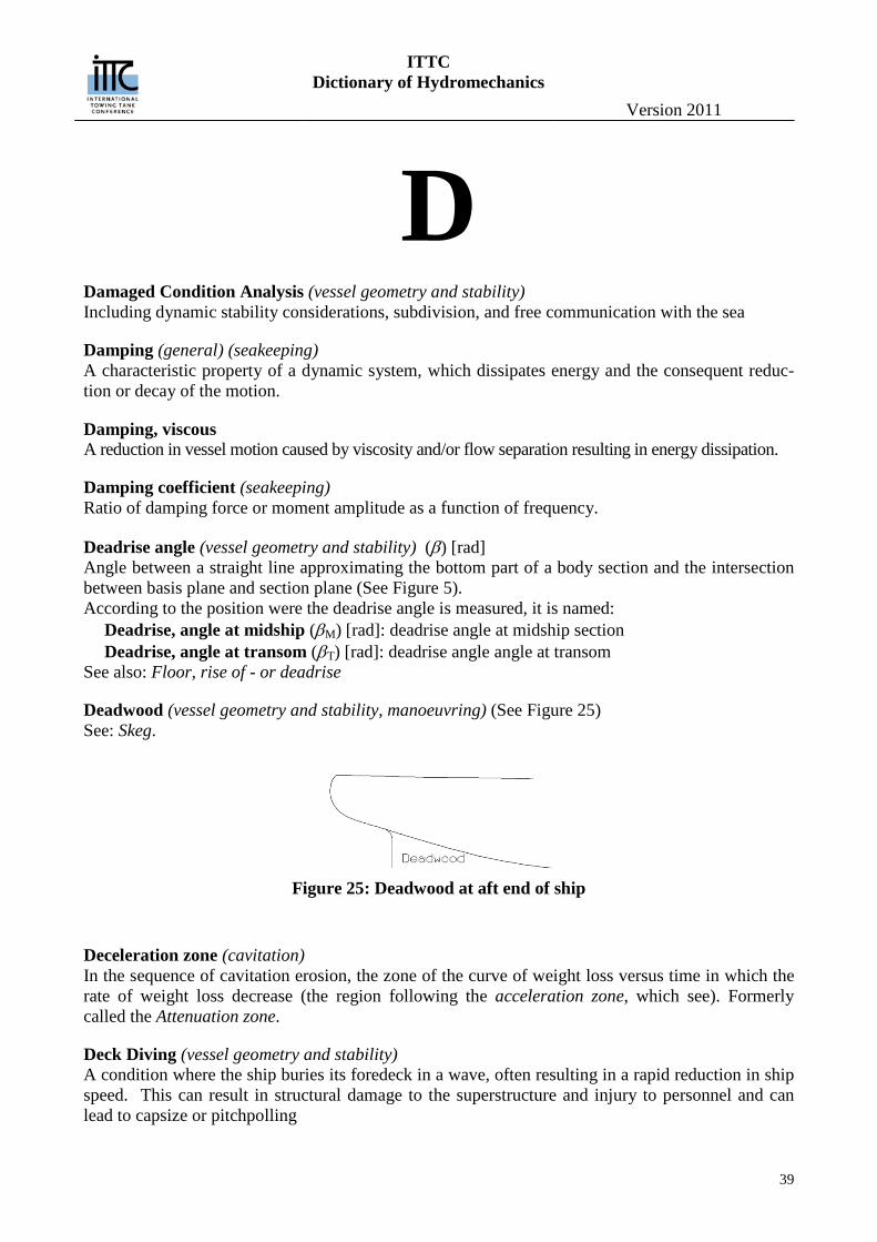
Deadwood (vessel geometry and stability, manoeuvring) (See Figure 25) See: Skeg.
Figure 25: Deadwood at aft end of ship
Deceleration zone (cavitation) In the sequence of cavitation erosion, the zone of the curve of weight loss versus time in which the rate of weight loss decrease (the region following the acceleration zone, which see). Formerly called the Attenuation zone.
Deck Diving (vessel geometry and stability) A condition where the ship buries its foredeck in a wave, often resulting in a rapid reduction in ship speed. This can result in structural damage to the superstructure and injury to personnel and can lead to capsize or pitchpolling
ITTC Dictionary of Hydromechanics
Version 2011
40
Delivered power (performance) See: Power, delivered.
Density, mass (general), ρ) [L-3 M] The mass per unit volume of a substance. *
Density, weight (general), (w) [L-2 M T-2] The weight per unit volume of a substance.
Depth, moulded of a ship hull (vessel geometry and stability) (D) [L] The moulded depth of a ship, defined as the height above the baseplane of the lowest point of a deck where it joins the side of ship.
Derivatives, stability and control (manoeuvring) The hydrodynamic forces and moments which enter into the equations of motion are usually classi-fied into three categories: static, rotary, and acceleration. The static derivatives are due to the com-ponents of linear velocity of the body relative to the fluid. Rotary derivatives are derived from an-gular velocity of the body and acceleration derivatives are from either linear or angular acceleration of the body.
Desinent cavitation (cavitation) Cavitation under conditions of pressure and velocity such that cavitation will be suppressed by a slight change in the ambient conditions: pressure increase and /or velocity reduction.
Deterministic System (general) is a system in which no randomness is involved in the development of future states of the system. Linear deterministic models thus produce the same output for a given starting condition. Non-linear deterministic models can produce multiple outputs. See also Chaotic Systems and Stochastic sys-tems
Developed area (propulsion, propulsor) See: Area, developed.
Developed area ratio (propulsion, propulsor) (aD)[-] The ratio of the developed area of the propeller blades to the disc area.
Diagonal (vessel geometry and stability) The trace on the outside of a body marking the intersection of a plane passing through it at an angle other than 90° to the baseplane. Specifically for a ship of normal form, the diagonal plane is gener-ally parallel to the baseline.
Diameter, steady-turning (manoeuvring) The diameter of the circular arc described by the centre of gravity of a ship when it has achieved a steady-turning state.
Diameter, tactical (manoeuvring) (See Figure 1) The distance travelled by the centre of gravity of the ship normal to its original approach path in turning through 180 degrees. Tactical diameter is equal to the transfer at 180 degrees change of heading.
ITTC Dictionary of Hydromechanics
Version 2011
41
Dihedral, Angle (vessel geometry and stability) (-) [-] The complement of the acute angle between the plane of symmetry of a craft or body and the axis of a hydrofoil attached to it projected on to a transverse plane.
Directional stability (manoeuvring) See: Stability, directional.
Displacement Mass (vessel geometry and stability) (ΔM) [M] The mass of the water that a body displaces while floating
Displacement Volume (vessel geometry and stability) (∇ ) [L3] The volume of water displaced by the molded submerged volume of the bare hull, plus all sub-merged appendages
Doublet (hydrodynamics) A source-sink pair where the axial spacing tends to zero as the product of axial spacing and the source strength remains constant. The value of that product is the “moment” of the doublet, and the direction from the sink to the source is the “axis” of the doublet. Consequently, a doublet of mo-ment M (dimension L4T-1) and of axis x located in a point A generates at any point P a velocity po-tential:
𝜙 = −𝑀
4𝜋𝑟2𝜕𝑟𝜕𝑥
= −𝑀
4𝜋𝑟2cos𝜃
Where r = AP and θ = angle between AP and axis x(1). If M< 0, the axis of the doublet would be in the negative x-direction. In two dimensional problems, the definition holds. But the potential gener-ated by a doublet of moment M (dimension L3T-1) and of axis x is:
𝜙 = −𝑀
2𝜋𝑟𝜕𝑟𝜕𝑥
= −𝑀
2𝜋𝑟cos𝜃
where r = AP and θ = angle between AP and axis x. (1) See: Potential function or Velocity potential.
Downflooding (vessel geometry and stability) (NSWCCD) — A consequence of an extreme motion that results in flooding. An example is where a large roll angle puts the intakes to the gas turbine into the water.
Downflooding angle (vessel geometry and stability) (θf) [rad] (NSCV) — the smallest angle of heel at which downflooding will occur, if all weathertight closing appliances are properly secured (see NSCV Figure 3 and Figure 6). NOTE: The downflooding an-gle is often calculated assuming the centre of transverse flotation remains at the centre line of the vessel. This approximation tends to become less accurate at larger angles of heel. It is normally conservative on vessels that have considerable reserve buoyancy, but can overstate the downflood-ing angle on vessels that have minimal reserve buoyancy.
Downwash or sidewash (manoeuvring) The deflection of a stream of fluid by any hydrofoil producing lift or thrust.
Downwash or Induced angle (manoeuvring) (αIND, formerly ε) [-]
ITTC Dictionary of Hydromechanics
Version 2011
42
The angle of downwash (which see) measured in a plane through the nose-tail line of the hydrofoil and perpendicular to the hydrofoil axis.
Drag (vessel geometry and stability) (-) [L] A designed trim. (American usage – See: Trim) (hydrodynamics) (D) [LMT-2] The fluid force acting on a moving body in such a way as to oppose its motion; the component of the fluid forces parallel to the axis of motion of a body. Drag is the preferred term in aerodynamics and for submerged hydrodynamic bodies, while resistance is generally used in ship hydrodynamics. The various forms of drag are defined in relation to resistance. See also Resistance.
Drag coefficient (hydrodynamics, manoeuvring) (CD) [-] A non-dimensional relationship between the drag D of a ship or body and the dynamic pressure times a specified area. It is customary to express it as 𝐶D = 𝐷 𝑞𝐴⁄ .
Draught (vessel geometry and stability) (T) [L] The vertical distance, from the water surface to the bottom, of the underwater body of a ship. Spe-cifically, the draught moulded, at midships to the design waterplane. When different, the draught at the transverse section having maximum area is indicated as TX
Drift (seakeeping, manoeuvring) That motion, or component of motion, caused by some action other than that of the main propulsion devices of a ship, such as wind, waves, current and like. See also: Sideslip.
Drift or sideslip, angle of (seakeeping) (β) [-] The horizontal angle between the instantaneous direction of motion of the centre of gravity of a ship and its longitudinal axis. It is positive in the positive sense of rotation about the vertical body’s axis.
Ducted propeller (propulsion, propulsor) See: Propeller Types.
Dynamic (general), As an adjective, pertains to motion as the result of force, or to bodies and system in motions; in this respect it is opposite of static (which see)
Dynamic pressure (hydrodynamics) See Pressure, dynamic
Dynamic stability (general, vessel geometry and stability, manoeuvring), — That property of body which cause it, when slightly disturbed from a steady motion, to resume that the same steady motion, usually along a different path, without any corrective control being ap-plied. See: Stability dynamic. — The characteristic of a body, such as an aircraft, rocket, or ship that causes it, when disturbed from an original state of steady motion in an upright position, to damp the oscillations set up by restoring moments and gradually return to its original state. (McGraw Hill Dictionary of Scientific and Technical Terms) See Equilibrium and Stability. — (IMO) is the resistance to stability failures in a seaway.
ITTC Dictionary of Hydromechanics
Version 2011
43
Dynamical systems (general) A part of the world which can be seen as a self-contained entity with some temporal behavior. In nonlinear dynamics, speaking about a dynamical system usually means to speak about an abstract mathematical system which is a model for such an entity. Mathematically, a dynamical system is defined by its state and by its dynamics. A damped pendulum is an example of a dynamical system. 1. Computability in complex dynamic systems: “The fundamental questions of complexity
theory refer to the measurement of the speed, computational time, storage capacity and so on, of algorithms. It is another question how one sets out to find more or less complex algorithms.” (Mainzer 2007, p 191)
2. “According to the 2nd law of thermodynamics, entropy is a measure of increasing disorder in iso-lated systems. The reversible process is extremely improbable. In information theory, entropy can be introduced as a measure of uncertainty of random variables” (Mainzer 2007, p 195)
3. Predictions in chaotic systems: (Mainzer 2007, p197) In chaotic systems with sensitive depen-dence on the initial states, there is a finite loss of information for predictions of the future, ac-cording to the decay of correlations between the past states and the future state of prediction. The finite degree of uncertainty of a predicted state increase linearly to the number of steps in the future, given the entire past. But in the case of noise, the Kolmogorov-Sinai (KS) entropy becomes infinite, which means a complete loss of predicting information corresponding to the decay of all correlations. The degree of uncertainty becomes infinite
4. “1/f spectra are typical of processes that organize themselves to a critical state at which many small interactions can trigger the emergence of a new, unpredicted phenomenon. Earthquakes, atmospheric turbulence, stock market fluctuations, and physiological processes of organisms are typical examples. Self-organization, emergence, chaos, fractality, and self-similarity are features of complex systems with nonlinear dynamics…White noise is characterized by the normal dis-tribution of the Gaussian bell curve, Pink noise with a 1/f spectrum is decidedly non-Gaussian. Its patterns are footprints of complex self-organizing systems.” (Mainzer 2007, p200) (A possi-ble explanation of how wave groups and swell waves form?)
ITTC Dictionary of Hydromechanics
Version 2011
44
E Edges, leading and trailing (manoeuvring) The upstream and downstream edges, respectively, of a hydrofoil, propeller blade, rudder or similar device.
Effective advance angle (propulsion, propulsor) See: Angle, effective advance.
Effective angle of attack (propulsion, propulsor) See: Angle of attack, effective.
Effective pitch (propulsion, propulsor) See: Pitch, effective.
Effective power (performance) See: Power, effective.
Effective wake fraction (performance) See: Wake fraction, effective.
Efficiency, gearing (performance) (ηG) [-] The ratio of the power output to the power input of a set of reduction – or multiplying – gears be-tween an engine and propulsion device:
SG
B
PP
η =
where PS and PB are the shaft and brake powers respectively (which see).
Efficiency, hull (performance) (ηH) [-] The ratio between the useful work done on the ship and the work done by the propeller or other propulsion devices in a given time that is effective power PE and thrust power PT respectively.
𝜂H = 𝑃E𝑃T
= 𝑅T𝑉𝑇𝑉A
= 1−𝑡1−𝑤
in Taylor notation
or
𝜂𝐻 = (1 + 𝑤F)(1− 𝑡) in Froude notation where RT is the total resistance, V the ship speed, T the propeller thrust and VA the speed of ad-vance; t is the thrust deduction fraction; w and wF are the wake fractions according to Taylor and Froude respectively (which see).
Efficiency, mechanical (propulsion, propulsor) (ηM) [-] The ratio between the power output and the power input of any machinery installation.
𝜂M =𝑃S𝑃I
ITTC Dictionary of Hydromechanics
Version 2011
45
or
𝜂M =𝑃B𝑃I
where PS and PB are the shaft and brake powers respectively and PI is the indicted power (which see).
Efficiency, propeller, behind hull (performance, propulsion, propulsor) (ηB) [-] The ratio between the power PT, developed by the thrust of the propeller and the power PD absorbed by the propeller when operating behind a model or ship:
𝜂B =𝑃T𝑃D
=𝑇𝑉A
2𝜋𝑄𝑛= 𝜂0𝜂R
where T is the thrust, VA speed of advance, Q shaft torque and n rate of propeller rotation; ηO and ηR are the open water propeller and relative rotative efficiencies respectively.
Efficiency propeller, open water (propulsion, propulsor performance) (η0) [-] The ratio between the power developed by the thrust of the propeller PT, and the power absorbed by the propeller PD when operating in open water with uniform inflow velocity VA:
𝜂0 =𝑃T𝑃D
=𝑇𝑉A
2𝜋𝑄0𝑛
where T is the thrust, Q0 the torque in open water and n the rate of propeller rotation.
Efficiency, propulsive (performance) (ηP) [-] The ratio between the useful or effective power PE and the brake power PB.
𝜂P =𝑃E𝑃B
= 𝜂0𝜂H𝜂R𝜂S𝜂G
where η0, ηH ηR ηS and ηG are the open water propeller, hull relative rotative shafting and gearing efficiencies respectively (which see).
Efficiency, quasi-propulsive or quasi-propulsive coefficient (propulsion, propulsor performance) (ηD) [-] The ratio between the useful or effective power PE and the power delivered to the propeller or the propulsion device PD.
𝜂D =𝑃E𝑃D
= 𝜂0𝜂H𝜂R
where η0, ηH and ηR are the open water propeller, hull and relative rotative efficiencies respectively (which see).
Efficiency, relative rotative (propulsion, propulsor, performance) (ηR) [-] The relative rotative efficiency is the ratio of the propeller efficiencies behind the hull and in open water, as already defined.
𝜂R =𝜂B𝜂0
ITTC Dictionary of Hydromechanics
Version 2011
46
Efficiency, shafting (performance) (ηS) [-] The shafting efficiency is a measured of the power lost in shaft bearings and stern tube:
𝜂S =𝑃D𝑃S
where PD and PS are the delivered and shaft powers respectively (which see).
Electrolytic effects (cavitation) Enhancement of cavitation erosion by electrochemical interactions due to local differences in the liquid or metal structure.
Emergence (seakeeping) () [L] The relative vertical distance of a part (usually the bow) of an oscillating ship above the water sur-face; opposite to submergence.
Emergence, tip (propulsion, propulsor) [L] The vertical distance from the top of the propeller tip circle to the at-rest water surface when the tips are exposed.
Entrance (vessel geometry and stability) See: Body.
Entrained gas content See: Gas content.
Equilibrium (general), A state of balance, between opposing forces or actions.
Equilibrium conditions: (general), Static equilibrium conditions: situations with no unbalanced forces and no accelerations. Quasi-static equilibrium conditions: situations with only slightly unbalanced forces and low ac-
celerations. Use of static equilibrium analysis techniques is an acceptable substitute in these conditions.
Near-equilibrium dynamic conditions: situations where using average or periodic unbalanced forces and assuming average or periodic accelerations is the only way to analytically solve otherwise complicated problems. This includes dynamic situations which can be assumed to be periodic or a stationary random process so that Fourier Transform methods are valid in the frequency domain.
Far-from-equilibrium dynamic conditions: significant unbalanced forces and complex accelera-tions make time domain analysis of the pressure and velocity field equations of fluid mechan-ics non-computable without extremely high computational times. This includes all situations in which a non-stationary random process is present. (Note that Newton’s Second Law for ri-gid bodies does not have these restrictions so body centric analysis is computable.)
Equilibrium and Stability (general) There are two classes of definitions for a dynamical system: one is motivated by ordinary differen-tial equations and is geometrical in flavor; and the other is motivated by ergodic theory and is measure theoretical in flavor. The measure theoretical assumes the existence of a measure-preserving transformation. This appears to exclude dissipative systems, as in a dissipative system a small region of phase space shrinks under time evolution
ITTC Dictionary of Hydromechanics
Version 2011
47
Equipotential line (hydrodynamics) A line in a potential flow field along which the velocity potential φ is constant.
Even Keel (vessel geometry and stability) This term is used to define the condition in which the ship has its keel parallel to the water surface. For vessels in which the keel is not straight or normally parallel to the water surface its use is not recommended: “zero trim” or “level trim” are preferred.
Expanded area (propulsion, propulsor) See: Area, expanded.
Expanded area ratio (propulsion, propulsor) (aE)[-] The ratio of the expanded area of the blades to the disc area.
External Validity (general) Is the extent to which the method (approach) is generalizable or transferable. A method's generali-zability is the degree the results of its application to a sample population can be attributed to the larger population. A method's transferability is the degree the method's results in one application can be applied in another similar application.
Extreme Event (vessel geometry and stability) An adverse ship motion and/or hydrodynamic loading event that, if it occurs, could cause loss of ship, loss of lives, crew injury and/or significant damage to the ship. Extreme Events include, but are not necessarily limited to, Capsize, Knock-down, Deck-diving, Broach, Slamming and Surf-ride.
ITTC Dictionary of Hydromechanics
Version 2011
48
F Face (of blade) (propulsion, propulsor) The side of the propeller blade which face downstream during ahead motion. This side of the blade is also known as the pressure side because the average pressure on the face of the blade is higher than the average pressure on the back of the blade during normal operation. The face corresponds to the lower surface of an airfoil or wing.
Face cavitation (cavitation) Cavitation occurring on the pressure side (face) of a propeller blade. It is generally a result of opera-tion such that the local blade angle of attack is excessively negative.
Face pitch (propulsion, propulsor) See: Pitch, face
Face Validity (general) Is the degree to which a method appears to be appropriate for doing what it intends to do. Face va-lidity is based on justifications provided by the state-of-art and state-of-practice knowledge and ex-perience.
Factor, appendage scale effect (performance) See: Appendage scale effect factor.
Factor, form (performance) See: Form factor.
Factor, load (performance) See: Power prediction factor.
Factor, magnification (seakeeping) The ratio of the output amplitude at a certain frequency to the static response.
Factor, ship-model correlation (performance) See: Correlation factor.
Factor, tuning (seakeeping) (Λ) [-] Ratio of excitation frequency to natural frequency or ratio of natural period of a motion to period of encounter. The tuning factor in heave, pitch and roll have the symbol
𝛬𝑍 =𝜔E
𝜔𝑍 𝛬𝜃 =
𝜔E
𝜔𝜃 𝛬𝜑 =
𝜔E
𝜔𝜑
or
𝛬𝑍 =𝑇Z𝑇E
𝛬𝜃 =𝑇𝜃𝑇E
𝛬𝜑 =𝑇𝜑𝑇E
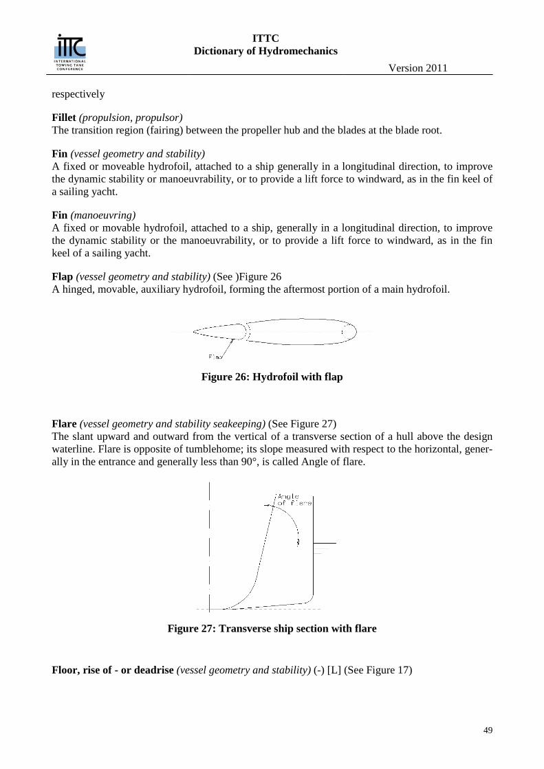
ITTC Dictionary of Hydromechanics
Version 2011
49
respectively
Fillet (propulsion, propulsor) The transition region (fairing) between the propeller hub and the blades at the blade root.
Fin (vessel geometry and stability) A fixed or moveable hydrofoil, attached to a ship generally in a longitudinal direction, to improve the dynamic stability or manoeuvrability, or to provide a lift force to windward, as in the fin keel of a sailing yacht.
Fin (manoeuvring) A fixed or movable hydrofoil, attached to a ship, generally in a longitudinal direction, to improve the dynamic stability or the manoeuvrability, or to provide a lift force to windward, as in the fin keel of a sailing yacht.
Flap (vessel geometry and stability) (See )Figure 26 A hinged, movable, auxiliary hydrofoil, forming the aftermost portion of a main hydrofoil.
Figure 26: Hydrofoil with flap
Flare (vessel geometry and stability seakeeping) (See Figure 27) The slant upward and outward from the vertical of a transverse section of a hull above the design waterline. Flare is opposite of tumblehome; its slope measured with respect to the horizontal, gener-ally in the entrance and generally less than 90°, is called Angle of flare.
Figure 27: Transverse ship section with flare
Floor, rise of - or deadrise (vessel geometry and stability) (-) [L] (See Figure 17)
ITTC Dictionary of Hydromechanics
Version 2011
50
The vertical distance above the baseline of the intersection point of the prolongation of the flat of the bottom at the maximum section area with a vertical straight line at half-beam from the centre-plane.
Flow, laminar (hydrodynamics) The flow of a viscous liquid in which layers of laminae of fluid appear to slide smoothly past each other. Momentum transfer and shear between neighbouring layers of fluid are due to molecular in-teractions only.
Flow, potential (hydrodynamics) A flow field in which the fluid velocity U is equal to the gradient of a scalar velocity potential φ, U =gradφ, i.e. in which no vorticity is present, curl U = 0. See also Potential function.
Flow, regime (hydrodynamics) A term referring to the state of the flow in any region; the principal recognised regimes are laminar, transitional, turbulent and separated flows.
Flow, reversed (hydrodynamics) Flow occurring in an eddy or separated zone in which the local flow has a component opposite in direction to that of the main flow.
Flow, secondary (hydrodynamics) A transverse flow induced by the boundary layer geometry and by pressure conditions existing in the main flow.
Flow, separated (hydrodynamics) The detachment of the main fluid flow from a solid surface due to an adverse longitudinal pressure gradient sometimes caused by a sudden change of the direction or the curvature of the surface. The fluid in the separated flow contains eddies, and may be nearly static or may contain a region of re-versed flow.
Flow, steady (hydrodynamics) Flow in which the velocity pattern is independent of time.
Flow, transitional (hydrodynamics) An unstable state of viscous flow between the laminar and turbulent regimes.
Flow, turbulent (hydrodynamics) A flow in which there are rapid and apparently random fluctuations both in the magnitude and in the direction of velocity. The velocity fluctuations may also be described by a random spectrum of vortices of varying size and strength. Turbulent resistance is higher than that in laminar flow at the same Reynolds number, because of the high momentum exchange by transverse fluctuations.
Flow, uniform (hydrodynamics) Flow in which all velocity vectors are parallel and equal.
Flow, viscous (hydrodynamics) The flow of a fluid where the flow characteristics include the effects of the shear forces acting on the fluid, and within it.
ITTC Dictionary of Hydromechanics
Version 2011
51
Fluid, perfect or ideal (hydrodynamics) A hypothetical fluid which is homogeneous, inviscid and incompressible.
Foam cavitation (cavitation) A cavitated region formed entirely of a mass of transient cavities so as to resemble foam (formerly called burbling cavitation).
Force components, hydrodynamic (manoeuvring) (X,Y, Z) [LMT-2] The components of the total hydrodynamic force on a body or ship as resolved along its x-, y- and z-axes respectively. Related to the flow over the body, the components are the drag component, D or R, in the direction of the relative flow; the lift component, L, in the principal plane of symmetry normal to the relative flow; the cross force, C, on the body normal to lift and drag.
Force, cross (manoeuvring) (C) [LMT-2] A force exerted on a body, a hydrofoil, or a ship, with or without an angle of attack, at right angles to both the direction of lift and the direction of drag. Note: This is to be carefully distinguished from the lateral force; see: Force, sway.
Force, damping (seakeeping) A force which tends to reduce the motion and, if assumed to be linear, is proportional to the veloc-ity.
Force exciting (seakeeping) A fluctuating external force that causes motion of body, as for instance, a ship when encountering a train of waves.
Force, restoring (seakeeping) A force tending to return a body to its initial condition when displaced by an external force.
Force, sway (manoeuvring) (Y) [LMT-2] The component of the total hydrodynamic force exerted by liquid on a body, acting perpendicular to the plane of symmetry. Specifically, the force developed on a ship, acting normal to the plane of symmetry, when the ship is caused to move sidewise in a horizontal plane, as in drifting, skidding or crabbing.
Force, wave shearing, horizontal or lateral (seakeeping) (FL) [MLT-2] That part of the inertial lateral shearing force acting on a cross section of a hull that is caused by the action of waves and ship motions.
Force, wave shearing, normal or vertical (FN) [MLT-2] That part of the inertial vertical shearing force acting on a cross section of a hull that is caused by the action of waves and ship motions.
Forefoot (vessel geometry and stability) The part of the bow of a ship at or near the intersection of the stem with the keel.
Form effect (performance) The difference between the viscous resistance of a model or a ship and the two dimensional friction resistance of a flat plate of the same length and wetted area and at the same speed in a given fluid.
ITTC Dictionary of Hydromechanics
Version 2011
52
The difference arises because of the augmented speed of flow around the ship form as compared with along a flat plate and the pressure resistance of viscous origin. See also: Form factor.
Form factor (performance) (k) [-] The ratio between the total viscous resistance coefficient of a model or a ship CV and the two di-mensional frictional resistance coefficient of a flat place CF0 at the same free stream Reynolds num-ber. It may be expressed in two ways, either:
V F0
F0
C Ck
C
or
V F
F
C Ck
C
Fraction overload (performance) See: Power prediction factor.
Fraction, resistance augment (performance) See: Resistance augment fraction.
Fraction, thrust deduction (performance) See: Thrust deduction fraction.
Fraction, wake See: Wake fraction.
Frame section (vessel geometry and stability) The intersection of the hull form with a vertical transverse plane, at the position of a transverse frame of the ship.
Freeboard (vessel geometry and stability, seakeeping) (f) [-] The vertical distance between the surfaces of the undisturbed water, in which a ship is floating, and the edge of a reference deck (Freeboard deck) or other reference point. In certain governmental load line rules, a minimum freeboard is specified at midship.
Free gas content (cavitation) See: Gas content.
Free streamline flow (cavitation) Fully developed cavity flow. For steady flows, the cavity walls are stream surfaces of the flow with the unique feature that the pressure is constant on the free streamlines. The term originates in the mathematical problem that the boundaries are “free” to be determined by the known condition of constant pressure.
Frequency (seakeeping) (f) [T-1] The number of cycles occurring per unit of time.
Frequency, circular (seakeeping) (ω) [T-1]
ITTC Dictionary of Hydromechanics
Version 2011
53
In any cyclic motion, or in any periodic motion which may be represented by a cyclic motion, the circular frequency is the angular velocity. If ω is in radiant per second, then
𝜔 = 2𝜋𝑇
and 𝑓 = 𝜔2𝜋
where T is the period and f is the frequency.
Frequency of wave (seakeeping) (fW) [T-1] The number per unit time of successive crests of a train of waves at a fixed angle of encounter, µ; the reciprocal of the wave period TW.
Frequency of wave encounter (seakeeping) (fE) [T-1] The number per unit time of successive crests of a train of waves meeting a fixed point of a ship, at a fixed angle of encounter, µ; the reciprocal of the period of encounter TE. In deep water:
𝑓E = 𝑓W +2𝜋𝑔𝑉𝑓𝑊2cos𝜇
where fW is wave frequency and V ship speed.
Frequency of wave encounter, circular (seakeeping) (ωE) [T-1]
𝜔E =2𝜋𝑇E
= 2𝜋𝑓E
Frequency, natural, of heave, pitch or roll of a ship (seakeeping) (fZ, fθ, or fϕ) [T-1] The frequency of the periodic heaving, pitching or rolling motion of a ship.
Frequency, natural circular, of heave, pitch or roll (seakeeping) (ωZ, ωθ or ωϕ) [T-1] Frequency, natural circular, of heave, pitch or roll has the following definitions respectively: 2𝜋𝑇𝑍
, 2𝜋𝑇𝜃
and 2𝜋𝑇𝜑
, where TZ , Tθ and Tϕ are the natural periods (which see).
Fresh water, standard (performance) See: Water, standard fresh.
Friction deduction force in self propulsion test (performance) (FD) [LMT-2] The towing force applied to a model to compensate for the increased specific frictional resistance of the model and to achieve the ship-point of self-propulsion.
Frictional resistance (resistance) See: Resistance
Frictional wake (performance) See: Wake, frictional.
Froude number (hydrodynamics) (Fr) [-] A dimensionless parameter expressing the conditions of dynamical similarity for flow systems in-fluenced by gravity and inertia alone. In particular it defines the speed at which geometrically simi-lar models and ship will develop wave systems which are geometrically similar. It is given by:
ITTC Dictionary of Hydromechanics
Version 2011
54
VFr
gL
The length term L is usually the length of the ship. Other forms of the Froude number use some other characteristic dimension, such as the cube root of volume of displacement, the submergence depth or the depth of water in restricted waterways.
Fully cavitating propeller (propulsion, propulsor) See: Propeller types.
Fully developed cavity (cavitation) A cavity formed on a body which terminates sufficiently far downstream so that the flow at the downstream region does not influence the body itself. For example, the cavity is fully developed when the re-entrant jet formed at the downstream end of the cavity is dissipated without impinging on the body. See also: Supercavitating flows.
ITTC Dictionary of Hydromechanics
Version 2011
55
G Gap (propulsion, propulsor) (GZ) [L ] The distance between the chord lines of two adjacent propeller blade sections measured normal to the chord. This distance is given by the formula:
𝐺𝑍 = (2𝜋𝑟 sin𝜑) 𝑍⁄
where r is the radius in question, ϕ is the pitch angle of the chord line at the radius r (geometric pitch) and Z is the number of blades.
Gas content (cavitation) (α) The gas content of a liquid may be in either a dissolved or undissolved state. The quantity of dis-solved gas will vary according to Henry’s law, but it is now generally agreed that cavitation incep-tion is associated with the gas contained in nuclei in an undissolved state (see: Nuclei and Nuclea-tion). Total gas content is equal to both the dissolved and undissolved gas. “Free” and “entrained” gas content are alternate terms for undissolved gas content, but the latter term is preferred.
Gas content of the saturated liquid (cavitation) (αS) The gas content of the saturated liquid at standard temperature and pressure.
Gas content ratio (cavitation) (aS) [-] The ratio of the content (dissolved and undissolved) in a test liquid to the gas content of the satu-rated liquid at standard temperature and pressure: 𝑎S = 𝛼 𝛼S⁄
Gas injection, protection by (cavitation) Small amounts of gas injected into the cavitating region to reduce the pressure through a “cushion-ing” effect during compression by the collapsing cavitation bubbles.
Gaseous cavitation (cavitation) Depending upon the magnitude of the pressure reduction and the rate of application, a bubble may grow slowly by diffusion gas into the nucleus (which see) and contain mostly gas rather than va-pour. Such bubble growth is defined as gaseous cavitation. Such cavitation may occur at pressure greater or less than vapour pressure aided by the process of Rectified diffusion (which see).
Gearing efficiency (performance) See: Efficiency, gearing.
Generator line (propulsion, propulsor) The line formed by the intersection of the pitch helices and the plane containing the shaft axis and the propeller reference line. The distance from the propeller plane to the generator line in the direc-tion of the shaft axis is called the rake. The generator line, the blade reference line, and the propeller reference line each intersect the shaft axis at the same point when extended thereto. Because of am-biguities which can arise in so extending the generator line and blade reference line when non linear distribution of rake and skew angle are used, it is recommended that these lines be defined each to
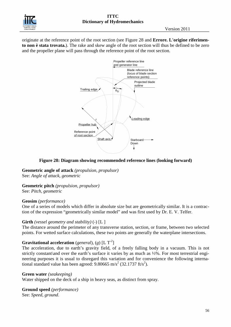
ITTC Dictionary of Hydromechanics
Version 2011
56
originate at the reference point of the root section (see Figure 28 and Errore. L'origine riferimen-to non è stata trovata.). The rake and skew angle of the root section will thus be defined to be zero and the propeller plane will pass through the reference point of the root section.
Figure 28: Diagram showing recommended reference lines (looking forward)
Geometric angle of attack (propulsion, propulsor) See: Angle of attack, geometric
Geometric pitch (propulsion, propulsor) See: Pitch, geometric
Geosim (performance) One of a series of models which differ in absolute size but are geometrically similar. It is a contrac-tion of the expression “geometrically similar model” and was first used by Dr. E. V. Telfer.
Girth (vessel geometry and stability) (-) [L ] The distance around the perimeter of any transverse station, section, or frame, between two selected points. For wetted surface calculations, these two points are generally the waterplane intersections.
Gravitational acceleration (general), (g) [L T-2] The acceleration, due to earth’s gravity field, of a freely falling body in a vacuum. This is not strictly constant\and over the earth’s surface it varies by as much as ½%. For most terrestrial engi-neering purposes it is usual to disregard this variation and for convenience the following interna-tional standard value has been agreed: 9.80665 m/s2 (32.1737 ft/s2).
Green water (seakeeping) Water shipped on the deck of a ship in heavy seas, as distinct from spray.
Ground speed (performance) See: Speed, ground.
sθ
Projected bladeoutline
Blade reference line(locus of blade sectionreference points)
Propeller reference lineand generator line
Trailing edge
Leading edger
Propeller hub
Reference pointof root section
Shaft axis StarboardDown

ITTC Dictionary of Hydromechanics
Version 2011
57
Group velocity (seakeeping) The average rate of advance of the energy of a finite train of gravity waves.
Gyradius (radius of gyration) (seakeeping) (kX, kXX, kY, kYY, kZ, kZZ) [L] The square root of the ratio of mass moment of inertia (referred to body axes) to the mass of a body. See: Axes, co-ordinate.
ITTC Dictionary of Hydromechanics
Version 2011
58
H Half-siding (vessel geometry and stability) (-) [L] (See Figure 17) The half breadth, at any section, of the portion of the bottom, in the vicinity of the keel that is per-pendicular to the centerplane, i.e. parallel to the baseline.
Harmonic (seakeeping) Sinusoidal, in referring to a function or motion.
Head (hydrodynamics) (h) [L] The height of a given fluid which the pressure in question would support.
Heading (manoeuvring, seakeeping, performance) (ψ) [ ] The instantaneous direction of the projection of the forward longitudinal axis of a ship in a horizon-tal plane, defined by degrees of the compass or degrees azimuth. See Figure 23., performance :See also Fig.2-4
Headreach (manoeuvring) See: Advance, maximum (in stopping).
Heaving (seakeeping) The vertical oscillatory motion of a specified point in a vessel, usually the centre of gravity. Al-though the heaving of a ship is a motion which is confined to operation in waves, it is possible with a high-speed planing craft for such motion to occur in calm water under some conditions. (See Por-poising)
Heave to (seakeeping) To maintain control of a ship, especially in extremely heavy weather, with minimum possible speed through the water.
Heel or list (manoeuvring, seakeeping) A steady inclination of a ship about a longitudinal axis; to be distinguished from rolling, which is an oscillatory motion.
Heel or list, angle of (manoeuvring, seakeeping) (φ) [-] The angle, measured about a longitudinal axis, between a static inclined position of a ship and its normal upright position.
Hub (propulsion, propulsor) The central portion of a screw propeller to which the blades are attached and through which the driving shaft is fitted. Also known as the boss.
Hub diameter (propulsion, propulsor) (dh) [L] The diameter of the hub where it intersect the propeller reference line (see.Figure 29).
Hub diameter, fore (dhf) [L] – Fore diameter of the hub, not considering any shoulder.
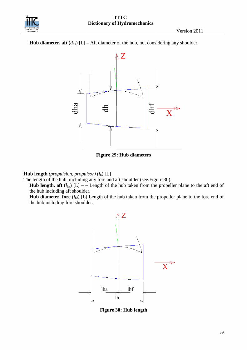
ITTC Dictionary of Hydromechanics
Version 2011
59
Hub diameter, aft (dha) [L] – Aft diameter of the hub, not considering any shoulder.
Figure 29: Hub diameters
Hub length (propulsion, propulsor) (lh) [L] The length of the hub, including any fore and aft shoulder (see.Figure 30).
Hub length, aft (lha) [L] – – Length of the hub taken from the propeller plane to the aft end of the hub including aft shoulder. Hub diameter, fore (lhf) [L] Length of the hub taken from the propeller plane to the fore end of the hub including fore shoulder.
Figure 30: Hub length
ITTC Dictionary of Hydromechanics
Version 2011
60
Hub cavitation (cavitation) See: Hub vortex cavitation.
Hub ratio (propulsion, propulsor) (xB) [-] The ratio of the diameter of the hub to the maximum diameter of the propeller, dh /D.
Hub vortex cavitation (cavitation) Cavitation in the vortex produced by the blades of a propeller at the hub.
Hull (vessel geometry and stability) The body of a ship, including the above water and the underwater portions. It is used to express ei-ther its form or its structure.
Hull efficiency (performance) See: Efficiency, hull.
Hull, naked (vessel geometry and stability) The condition of a ship or model in which the fair form and the surface are represented without ap-pendages or additions of any kind; it is also called bare hull.
Hydraulically smooth surface (performance) See: Surface, smooth.
Hydrodynamic flow angle (propulsion, propulsor) See: Angle, hydrodynamic flow.
Hydrodynamic pitch (propulsion, propulsor) See: Pitch, hydrodynamic.
Hydrodynamic pitch angle (propulsion, propulsor) Synonymous with hydrodynamic flow angle. See: Angle, hydrodynamic flow.
Hydrodynamic spindle toque (propulsion, propulsor) See: Spindle torque, hydrodynamic.
Hydroelasticity (seakeeping) Analogous to aeroelasticity. The study of the interaction between the inertial, hydrodynamic and elastic forces in a structure subjected to hydrodynamic loading. Divided into dynamic hydroelastic-ity, where these three forces are co-existent, or static hydroelasticity where inertial forces are ab-sent.
Hydrofoil (propulsion, propulsor) A structure externally similar to an airplane wing designed to produce lift and which operates in wa-ter.
Hydrofoil section (propulsion, propulsor) The cross-section shape of a hydrofoil.
Hydrofoil, span (vessel geometry and stability) (b) [L]
ITTC Dictionary of Hydromechanics
Version 2011
61
The length of a hydrofoil from tip to tip, from root to tip if cantilevered, or from end support to end support, measured normal to the direction of relative liquid motion.
Hysteresis, cavitation (cavitation) Difference between critical cavitation numbers for incipient and desinent cavitation. Also, the dif-ference between the angle of attack of a lifting surface for initiation or fully developed cavitation during angle of attack increase and the much lower angle of attack at which a fully developed cavity can still be maintained once it has been formed.
ITTC Dictionary of Hydromechanics
Version 2011
62
I Ideal angle of attack (propulsion, propulsor) See: Angle of attack, ideal.
Immersion (propulsion, propulsor) (h0) [-] The depth of submergence of the propeller measured vertically from the shaft axis to the free sur-face.
Immersion ratio (propulsion, propulsor) [-] The depth of submergence of the propeller axis divided by propeller diameter.
Impact (seakeeping) The sudden contact of body or ship, or any part thereof, with the surface of a liquid.
Impaired Static Stability (vessel geometry and stability) (DCM) conditions under which an intact hull suffers a reduction in its normal stability characteris-tics caused by:
1. Addition of topside weight, 2. Removal of low weight 3. Shifting of cargo 4. Other off center weight shifts and additions including free surface effects 5. Deterioration of reserve buoyancy (including water trapped on deck) 6. Flooding
Inboard rotation (propulsion, propulsor) A propeller which is not located on the centreline of the ship is said to have inboard rotation if the blade moves toward the centreline as they pass the upper vertical position. The opposite direction of rotation is called outboard rotation. Also called inward and outward rotation respectively.
Inception of cavitation (cavitation) See: Cavitation inception.
Inception cavitation number (cavitation) See: Cavitation number, inception.
Inception pressure See: Critical pressure.
Inception velocity (cavitation) See: Critical velocity.
Incipient cavitation (cavitation) Cavitation which just begins with a slight change in ambient conditions: pressure decrease and/or velocity increase.
ITTC Dictionary of Hydromechanics
Version 2011
63
Incubation zone (cavitation) In the sequence of cavitation erosion, the initial zone of the curve of weight loss versus time in which the material undergoes changes (e.g. work hardening in ductile metals) due to repeated bub-ble collapse pressures, but in which the material suffers little or no weight loss.
Independent Failures (general) vs. Dependent Failures — The overriding problem in risk assessment is to differentiate between the dependent failure and that of the independent failure. It is much simpler to predict the frequen-cy of independent failures for which the probabilities are knowable. Dependent failures involve conditional probabilities which are much more complex. To this end there have been many model-ing methods, mostly theoretically based, which lack a practicable engineering approach to a satis-factory understanding and solution.
Indicated power (performance) See: Power, indicated.
Induced velocity, axial (propulsion, propulsor) (UA) [LT-1] The change in the velocity component in the direction parallel to the propeller axis due to the pres-ence of the propeller but not including any change in the wake field due to propeller/hull interac-tions. Positive upstream. (See Figure 3)
Induced velocity, radial (propulsion, propulsor) (UR) [LT-1] The change in the velocity component in the radial direction due to the presence of the propeller but not including any change in the wake field due to propeller/hull interactions. Positive outward.
Induced velocity, tangential (propulsion, propulsor) (UT) [LT-1] The change in the velocity component in the tangential direction due to the presence of the propeller but not including any change in the wake field due to propeller/hull interactions. Positive clockwise looking forward. (see Figure 3).
Inertial instability (general) generally, instability in which the only form of energy transferred between the steady state and the disturbance in the fluid is kinetic energy. (McGraw Hill Dictionary of Scientific and Technical Terms Intact Stability Failure (vessel geometry and stability) (IMO) Is a state of inability of a ship to remain within design limits of roll (heel, list) angle and combination of lateral and vertical accelerations.
Intensity damage (cavitation) The power absorbed per unit eroded area of a specimen undergoing erosion.
Interactive Complexity (general) (Bookstaber, 2007) —Is a measure of the way the components of a system connect and relate. An inte-ractively complex system is one whose components can interact in unexpected or varied ways, where there is feedback that can lead the components to differ in their state or their relationship with the rest of the system from one moment to the next, where the possible stages and interactions are not clearly apparent or cannot be readily anticipated. Systems with high levels of interactive complexity are sub-ject to failures that seem to come out of nowhere or that appear unfathomably improbable (Black Swan events, Taleb, 2007).
ITTC Dictionary of Hydromechanics
Version 2011
64
Intermittent cavitation (cavitation) A type of cavitation that respectively originates and disappears from a discrete point on a solid sur-face.
Internal jets (cavitation) Jets sometimes formed by the unsymmetrical collapse of transient cavities. Also sometimes called microjets.
Internal Validity (general) Is the basic minimum without which the method is uninterpretable. Internal validity of a method addresses the rigor with which a method is conducted - how it is designed, the care taken to conduct measurements, and decisions concerning what was and wasn't measured. There are four different types of internal validity: 1) face, 2) content, 3) criterion-related, and 4) construct.
Inward rotation (propulsion, propulsor) See: Inboard rotation.
Irrotational flow See Flow, potential.
ITTC Dictionary of Hydromechanics
Version 2011
65
J Jet cavitation (cavitation) Cavitation formed in the low pressure eddies associated with the turbulent fluctuations in the high shear region of jet flows.
Joint Probability (general) Is the probability of two events in conjunction. That is, it is the probability of both events together. The joint probability of A and B is written P(A′B) or P(A,B)
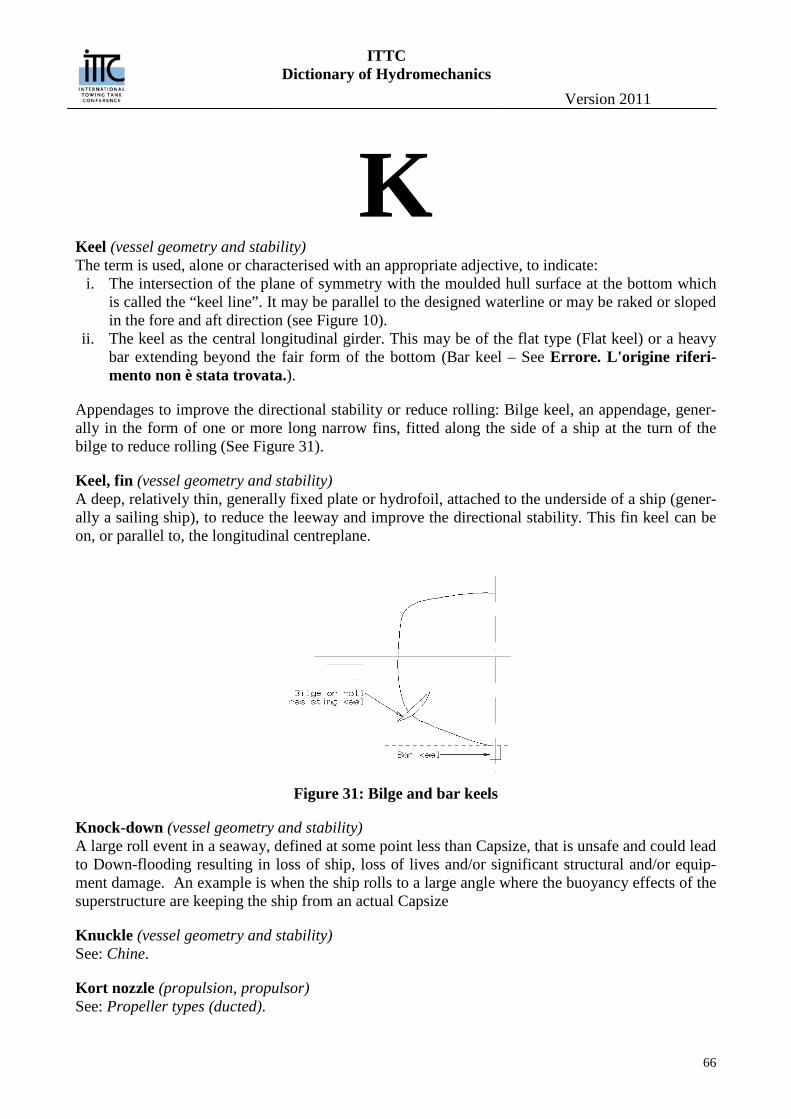
ITTC Dictionary of Hydromechanics
Version 2011
66
K Keel (vessel geometry and stability) The term is used, alone or characterised with an appropriate adjective, to indicate:
i. The intersection of the plane of symmetry with the moulded hull surface at the bottom which is called the “keel line”. It may be parallel to the designed waterline or may be raked or sloped in the fore and aft direction (see Figure 10).
ii. The keel as the central longitudinal girder. This may be of the flat type (Flat keel) or a heavy bar extending beyond the fair form of the bottom (Bar keel – See Errore. L'origine riferi-mento non è stata trovata.).
Appendages to improve the directional stability or reduce rolling: Bilge keel, an appendage, gener-ally in the form of one or more long narrow fins, fitted along the side of a ship at the turn of the bilge to reduce rolling (See Figure 31).
Keel, fin (vessel geometry and stability) A deep, relatively thin, generally fixed plate or hydrofoil, attached to the underside of a ship (gener-ally a sailing ship), to reduce the leeway and improve the directional stability. This fin keel can be on, or parallel to, the longitudinal centreplane.
Figure 31: Bilge and bar keels
Knock-down (vessel geometry and stability) A large roll event in a seaway, defined at some point less than Capsize, that is unsafe and could lead to Down-flooding resulting in loss of ship, loss of lives and/or significant structural and/or equip-ment damage. An example is when the ship rolls to a large angle where the buoyancy effects of the superstructure are keeping the ship from an actual Capsize
Knuckle (vessel geometry and stability) See: Chine.
Kort nozzle (propulsion, propulsor) See: Propeller types (ducted).
ITTC Dictionary of Hydromechanics
Version 2011
67
Kurtosis (general) (from the Greek word κυρτός, kyrtos or kurtos, meaning bulging) is a measure of the "peakedness" of the probability distribution of a real-valued random variable. Higher kurtosis (leptokurtic distri-bution) means more of the variance is due to infrequent extreme deviations, as opposed to frequent modestly-sized deviations
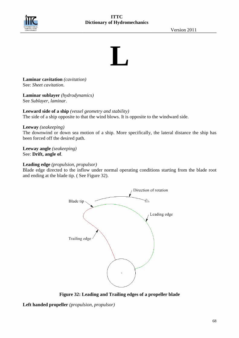
ITTC Dictionary of Hydromechanics
Version 2011
68
L Laminar cavitation (cavitation) See: Sheet cavitation.
Laminar sublayer (hydrodynamics) See Sublayer, laminar.
Leeward side of a ship (vessel geometry and stability) The side of a ship opposite to that the wind blows. It is opposite to the windward side.
Leeway (seakeeping) The downwind or down sea motion of a ship. More specifically, the lateral distance the ship has been forced off the desired path.
Leeway angle (seakeeping) See: Drift, angle of.
Leading edge (propulsion, propulsor) Blade edge directed to the inflow under normal operating conditions starting from the blade root and ending at the blade tip. ( See Figure 32).
Figure 32: Leading and Trailing edges of a propeller blade
Left handed propeller (propulsion, propulsor)

ITTC Dictionary of Hydromechanics
Version 2011
69
A propeller which rotates in the counterclockwise direction when viewed from astern.
Length (vessel geometry and stability) (L) [L] (See Figure 33) The principal longitudinal dimension of a ship or body; specifically for a ship it can be defined in a number of ways as follows:
Length overall (LOA) [L] Length overall submerged (LOS) [L] Length between perpendiculars (LPP) [L] Length on waterline (LWL) [L]
When not defined, the length between perpendiculars is generally assumed. See also Amidships for and Perpendiculars for AP and FP.
For a planing hull the following definitions of length are used: (See Figure 34)
Figure 33: Characteristic ship lengths
Figure 34: Characteristic lengths for a planing hull under way
Length, chine wetted under way of planing craft (vessel geometry and stability) (LC) [L]: the length of the wetted part of the chine Length, keel wetted under way of planing craft (vessel geometry and stability) (LK) [L]: the length of the wetted part of the keel
DWL
LOA
LPP
LWL
LOS
==
MPAP FP
LC
LK
Chine
Spray root line
KeelO
O
A
A
B
B
ITTC Dictionary of Hydromechanics
Version 2011
70
Length, mean wetted, of planing craft (vessel geometry and stability) (LM) [L]: the mean length of the portion of the bottom of a planing craft actually wetted when under way
C KM 2
L LL += .
Length, projected chine (vessel geometry and stability) (LPR) [L]: Length of chine projected in a plane containing the keel and normal to longitudinal centre plane (See Figure 5Errore. L'ori-gine riferimento non è stata trovata. and Figure 6).
Length characteristic of R. E. Froude (vessel geometry and stability) (U) [L] R. E. Froude’s dimensionless characteristic length 1/3U ∇=
Length coefficient of Froude, or length – displacement ratio (vessel geometry and stability) (MC) [-] The ratio of the ship length to the cube root of the volume of displacement:
𝑀C =𝐿
𝛻13
in a consistent system of units.
Lift (propulsion, propulsor) (L) [MTL-2] The fluid force acting on a body in a direction perpendicular to the motion of the body relative to the fluid.
Lift coefficient (manoeuvring) (CL) [-] A relationship between the lift force L developed by a ship or body and the dynamic pressure times a specified area. It is customary to express it as LC L qA .
Line, equipotential (hydrodynamics) See Equipotential line.
Lines (vessel geometry and stability) A drawing, depicting the form of a ship to the moulded shape and dimensions, showing the stations (transverse section or frames) waterlines, bowlines, buttocks and profile. (This includes a Body Plan which see.)
List (seakeeping) See: Heel
Load factor (performance) (1+x) [-] See: Power prediction factor.
Load fraction in power prediction (performance) (x) [-]
𝑥 = 𝜂D𝑃D𝑃E
− 1
where PD and PE are the delivered and effective powers respectively and ηD the quasi-propulsive efficiency (which see). See also: Power prediction factor.
ITTC Dictionary of Hydromechanics
Version 2011
71
Long crested seas (seakeeping) A wave system in which all components advance in the same direction.
Loose Coupling (general) Loose coupling means that the component failures of a linear system can be considered as having inde-pendent probabilities and thus joint probabilities are computable.
Low Frequency Large Amplitude Yaw Motions (vessel geometry and stability) This typically happens at higher ship speeds in moderate stern-quartering seas. A gradual build-up of oscillations in yaw occurs as successive waves impinge on the ship from behind. As the motion hits resonance, yaw amplitude increases until large amplitude yaw motions are displayed.
Lurch (seakeeping) A more or less isolated large roll amplitude.
ITTC Dictionary of Hydromechanics
Version 2011
72
M Maierform (vessel geometry and stability) A commercial name applied to a certain type of hull form with pronounced V sections at the fore end.
Manoeuvrability (manoeuvring) Manoeuvrability is that quality which determinates the ease with which the speed, attitude and di-rection of motion of a body can be changed or maintained by its control devices.
Manoeuvring (manoeuvring) The process of executing various voluntary evolutions with a ship, such as starting, stopping, back-ing, steering, turning, diving, rising, circling, zigzagging, dodging and the like.
Marginal probability (general) Is then the unconditional probability P(A) of the event A; that is, the probability of A, regardless of whether event B did or did not occur. If B can be thought of as the event of a random variable X having a given outcome, the marginal probability of A can be obtained by summing (or integrating, more generally) the joint probabilities over all outcomes for X. For example, if there are two possi-ble outcomes for X with corresponding events B and B', this means that P(A) = P(A′B) + P(A′B'). This is called marginalization
Mass, added (manoeuvring, seakeeping) See: Added mass
Mass, added, coefficient (manoeuvring, seakeeping) See: Added mass coefficient.
Mass Characteristics (vessel geometry and stability) Quantitative description of the mass and mass distributions of the ship (i.e., mass and mass distribu-tions that establish the ship’s lateral and transverse centers of mass and mass moments of inertia).
Maximum transverse section coefficient (vessel geometry and stability) See: Sectional area coefficient.
Mean (general) In statistics, mean has two related meanings: the arithmetic mean (and is distinguished from the geometric mean or harmonic mean). the expected value of a random variable, which is also called the population mean
Mean chord length (propulsion, propulsor) See: Chord length, mean.
Mean line (propulsion, propulsor)
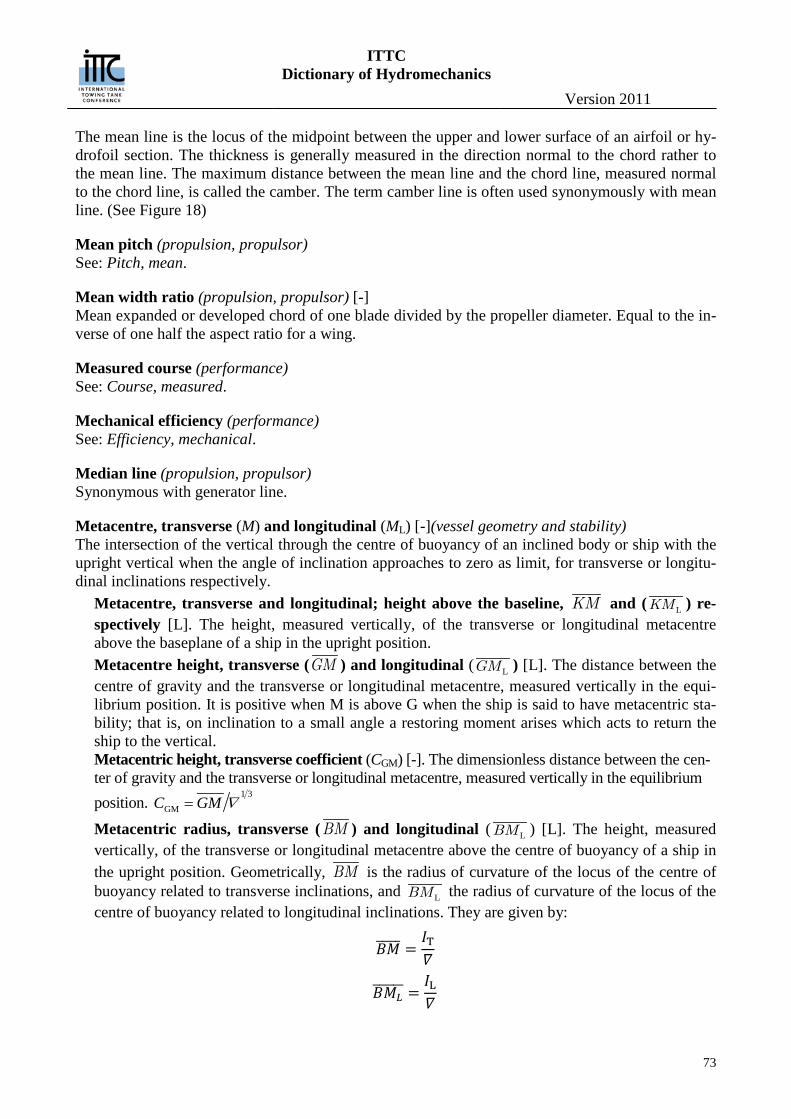
ITTC Dictionary of Hydromechanics
Version 2011
73
The mean line is the locus of the midpoint between the upper and lower surface of an airfoil or hy-drofoil section. The thickness is generally measured in the direction normal to the chord rather to the mean line. The maximum distance between the mean line and the chord line, measured normal to the chord line, is called the camber. The term camber line is often used synonymously with mean line. (See Figure 18)
Mean pitch (propulsion, propulsor) See: Pitch, mean.
Mean width ratio (propulsion, propulsor) [-] Mean expanded or developed chord of one blade divided by the propeller diameter. Equal to the in-verse of one half the aspect ratio for a wing.
Measured course (performance) See: Course, measured.
Mechanical efficiency (performance) See: Efficiency, mechanical.
Median line (propulsion, propulsor) Synonymous with generator line.
Metacentre, transverse (M) and longitudinal (ML) [-](vessel geometry and stability) The intersection of the vertical through the centre of buoyancy of an inclined body or ship with the upright vertical when the angle of inclination approaches to zero as limit, for transverse or longitu-dinal inclinations respectively.
Metacentre, transverse and longitudinal; height above the baseline, KM and ( LKM ) re-spectively [L]. The height, measured vertically, of the transverse or longitudinal metacentre above the baseplane of a ship in the upright position. Metacentre height, transverse (GM ) and longitudinal ( LGM ) [L]. The distance between the centre of gravity and the transverse or longitudinal metacentre, measured vertically in the equi-librium position. It is positive when M is above G when the ship is said to have metacentric sta-bility; that is, on inclination to a small angle a restoring moment arises which acts to return the ship to the vertical. Metacentric height, transverse coefficient (CGM) [-]. The dimensionless distance between the cen-ter of gravity and the transverse or longitudinal metacentre, measured vertically in the equilibrium position.
1 3
GMC GM ∇=
Metacentric radius, transverse (BM ) and longitudinal ( LBM ) [L]. The height, measured vertically, of the transverse or longitudinal metacentre above the centre of buoyancy of a ship in the upright position. Geometrically, BM is the radius of curvature of the locus of the centre of buoyancy related to transverse inclinations, and LBM the radius of curvature of the locus of the centre of buoyancy related to longitudinal inclinations. They are given by:
𝐵𝑀����� =𝐼T𝛻
𝐵𝑀𝐿������ =𝐼L𝛻
ITTC Dictionary of Hydromechanics
Version 2011
74
where: IT = transverse second moment of area (or moment of inertia ) of the waterplane [L4] (which see) IL = longitudinal second moment of area (or moment of inertia) of the waterplane [L4] (which see) ∇ = volume of displacement [L3]
(See Figure 35Errore. L'origine riferimento non è stata trovata. for illustration of the transverse parameters.)
Figure 35: Transverse metacentric parameters
Microjets (cavitation) See: Internal jets.
Midship (vessel geometry and stability) See: Perpendiculars
Midship section coefficient (vessel geometry and stability) See: Sectional coefficient
Midstation plane (vessel geometry and stability) See: Planes, principal co-ordinate
Mile, measured. (performance) See: Course measured.
Modulus of elasticity, volume or bulk (general), (E) [L-1 M T-2] The ratio of the stress, or force per unit area, to the corresponding change of volume per unit vol-ume.
Moment of area, second (or moment of inertia) (vessel geometry and stability) [L4] The summation of the products of the elements of an area or surface squares and the squares of their distances from a given axis, generally in the surface. Especially for a ship:
Second moment of the waterplane area (or moment of inertia) longitudinal (IL) about the transverse axis through the centre of flotation. Second moment of the waterplane area (or moment of inertia), transverse (IT) about the longitudinal axis through the centre of flotation, generally the intersection of the intersection of the waterplane and the centerplane.
KM
KG
KB
BM
GM
M
B
G
B'
K
WL
WL'
ITTC Dictionary of Hydromechanics
Version 2011
75
Second moment of free-water surface (or moment of inertia) generally within a ship, calcu-lated about an axis passing through the centre of area of that surface, parallel to the expected heeling or rolling axis.
Moment, damping (seakeeping) A moment which tends to reduce the motion and, if assumed to be linear, is proportional to the an-gular velocity.
Moment, destabilising (seakeeping) A moment associated with a displacement from a position of equilibrium and tending to increase this displacement.
Moment, exciting (seakeeping) A fluctuating external moment that causes motion of a body or ship when encountering a train of waves.
Moments of inertia or roll, pitch and yaw moment of inertia (seakeeping) (IX ,IXX, IY ,IYY, IZ ,IZZ) [L2M] The summation of products of elementary masses and the squares of their distances from the re-spective body axes through the centre of gravity – equal to the mass times the square of the gyra-dius or radius of gyration (which see). See General Section for body axes under Axes, co-ordinate.
Moment, pitching (seakeeping) Exciting moment in pitch.
Moment, restoring or righting (seakeeping) A moment tending to return a body to its initial condition after being displaced by an external mo-ment.
Moment, rolling (seakeeping) Exciting moment in roll.
Moment, stabilising (seakeeping) Moment associated with a displacement from a position of equilibrium and tending to decrease this displacement.
Moment, turning (manoeuvring) A moment applied to a ship to cause it to assume angular dynamic motion about a vertical axis through the centre of gravity.
Moment, wave bending, horizontal or lateral (seakeeping) (MB3 or ML, formerly MBH) [L2MT-2]
That part of the inertial lateral bending moment acting on a cross section of a hull which is caused by the action of waves and ship motions.
Moment, wave bending, vertical (seakeeping) (MB2 or MN , formerly MBV) [L2MT-2]
That part of the internal vertical bending moment acting on a cross section of a hull which is caused by the action of waves and ship motions.
Moment, wave, torsional (seakeeping) (MT or MT) [L2MT-2]
ITTC Dictionary of Hydromechanics
Version 2011
76
That part of the internal torsional or twisting moment acting on a cross section of a hull which is caused by the action of waves and ship motions.
Moment, yaw (manoeuvring) (N) [L2MT-2] A hydrodynamic moment due to environmental conditions acting on a ship which will tend to pro-duce yawing in the form of an angular dynamic motion about the vertical or z-axis through the cen-tre of the ship.
Motions, ship (seakeeping) The all inclusive term to describe the various dynamic motions which may be made by a ship in-cluding the following which are defined separately:
i. Rolling, Pitching and Yawing (angular) ii. Heaving, Surging and Swaying (translatory)
These motions may occur while the ship is stationary in the water or travelling through it.
Moulded (vessel geometry and stability) An adjective used to indicate the generally fair form and dimensions of the hull as determined by the lines to the inside of the shell plating. For wooden ship it is taken to the outside of the planking.
ITTC Dictionary of Hydromechanics
Version 2011
77
N Natural period of motions: heave, pitch, roll (seakeeping) (TZ, Tθ, Tϕ) [Τ] The time for one complete cycle of the motion resulting when a body or ship is displaced in calm water from its equilibrium position by an external force, then released.
Neutral angle (manoeuvring) The angle between any characteristic line or plane of a body or ship and any other intersecting line or plane taken as reference, when the forces, moments or other actions on or by the body or ship have a value of zero.
Nominal pitch (propulsion, propulsor) See Pitch, nominal.
Non-normal Distribution (general) The possibility should be considered that the underlying distribution of the data is not approximate-ly normal, and may have "fat tails". For instance, when sampling from a Cauchy distribution, the sample variance increases with the sample size, the sample mean fails to converge as the sample size increases, and outliers are expected at far larger rates than for a normal distribution
Non-stationary cavities (cavitation) Free-streamline (cavitating) flows in which the cavity size is a function of time. The cavity surface is a boundary surface, but not necessarily a stream surface. Cavities trailing a body entering a water surface are characteristic of non-stationary cavities.
Normal Accident (general) (Perrow, 1999) — The cascade of failure that occurs in systems that share tight coupling and com-plexity gives rise to what are called normal accidents.' As ironic as the term sounds, normal accidents are accidents that are to be expected; they are an unavoidable result of the structure of the process. The more complex and tightly coupled the system, the greater the frequency of normal accidents. The probability of any one event is small enough to be dismissed, but taken together, with so many possi-ble permutations and with combinations beyond comprehension, the odds of one or the other happen-ing are high.
Note also that a normal accident sequence involving potential loss of life can be interrupted by lucky human intervention. These involve non-computable probabilities such as having an expe-rienced glider pilot at the controls of a commercial aircraft struck in both engines by birds. Exam-ples of non-interrupted accident sequences: capsizing caused by being in the wrong place (i.e. the focal point of a rogue wave or microburst) at the wrong time (when it breaks or strikes) even if the vessel satisfies existing stability criteria. Normal accidents include rare events which are frequently called Black Swan events in the popu-lar press. These events lie outside the realm of regular expectations, because nothing in the past can convincingly point to its possibility. Second, it carries an extreme impact. Third, in spite of its outlier status, human nature makes us concoct explanations for its occurrence after the fact, making it explainable and predictable. Tight coupling system failures are generally rare, pre-
ITTC Dictionary of Hydromechanics
Version 2011
78
viously not experienced and involve unknown but non-zero retrospective probabilities. Ex-amples: penetrating the Maginot Line in 1940; the 9/11/2001 terrorist attacks; the conse-quences of the Pacific tsunamis of December 2004 and March 2011 and so on. Note: these examples may be normal accidents to knowledgeable persons in particular disciplines who recognize that such tightly coupled events have non-zero probabilities which are not com-putable. Actually, the majority of normal accidents arise from non-repeating sequences of events. These events can be analyzed using statistical hindcasts (a weather term) for modifi-cation to assumed “fat-tail” probabilities, but not accurately forecast since this new se-quence of events has never happened before. Note the different sequences in the Market Crashes of 1987 and 2008, the oil drilling spill of 1979 and 2010,and the accidents involv-ing the space shuttles Columbia and Challenger.
Normal Distribution (general) In probability theory, the normal (or Gaussian) distribution is a continuous probability distribu-tion that is often used as a first approximation to describe real-valued random variables that tend to cluster around a single mean value. The graph of the associated probability density function is "bell"-shaped, and is known as the Gaussian function or bell curve:
where parameter μ is the mean (location of the peak) and σ 2 is the variance (the measure of the width of the distribution). The distribution with μ = 0 and σ 2 = 1 is called the standard normal. The normal distribution arises as the outcome of the central limit theorem, which states that under mild conditions the sum of a large number of random variables is distributed approximately normal-ly. Finally, the "bell" shape of the normal distribution makes it a convenient choice for modeling a large variety of random variables encountered in practice.
Nose-tail line (propulsion, propulsor) Synonymous with chord line.
Nozzle (propulsion, propulsor) The duct portion of a ducted propeller. Synonymous with duct or shroud.
Nucleation (cavitation) The process of formation of nuclei in liquid. Also, sometimes used to refer to the process of stabili-sation of nuclei to account for their persistence in undersaturated and saturated liquids.
Nucleus, nuclei (cavitation) Small bubbles, often sub-microscopic in size, containing permanent gas and/or the vapour of the liquid, which are required for inception of cavitation at the pressure near vapour pressure. (See also: Nucleation).
Number, Froude (hydrodynamics) See Froude number.
Number, Reynolds (hydrodynamics) See Reynolds number.
ITTC Dictionary of Hydromechanics
Version 2011
79
O Offset (vessel geometry and stability) One of a series of distances, measured from reference planes (normally from the centerplane), used for defining the size and the shape of a body or ship.
Ogival section (propulsion, propulsor) A type of an airfoil or hydrofoil section having a straight face, a circular arc or parabolic back, maximum thickness at the mid chord, and relatively sharp leading and trailing edges.
Onset cavitation (cavitation) See: cavitation inception
Open Vessel (vessel geometry and stability) (NSCV) — a vessel that is not arranged to prevent the accumulation of large quantities of water on deck or in buoyant spaces if swamped. Such vessels—
1. are not provided with a deck that is effectively weathertight; 2. have a freeboard deck line that is in whole or part located below the deepest waterline; or
have weather decks forming wells above the deepest waterline that are not arranged for rap-id drainage of large quantities of accumulated water.
Orange peel surface appearance (cavitation) Description of a surface moderately damaged by the cavitation in which the appearance is that of the surface of the Jaffa or California orange.
Oscillator (seakeeping) A mechanism used to impose a controlled, known, oscillatory motion on a body. Also used to de-scribe any oscillatory body.
Outboard rotation (propulsion, propulsor) A propeller which is not located on the centreline of the ship is said to have outboard rotation if the blades move away from the centreline as they pass the upper vertical position. The opposite direc-tion of rotation is called inboard rotation. Also called outward and inward rotation respectively.
Outward rotation (propulsion, propulsor) See: Outboard rotation.
Overhang (vessel geometry and stability) Any portion of the abovewater hull of a ship which when projected downward on to the designed waterplane, lies outside that designed waterline; it may be at the bow or stern or anywhere along the side.
Overload fraction (performance) See: Power prediction factor.
ITTC Dictionary of Hydromechanics
Version 2011
80
Overshoot (manoeuvring) A state of motion of a body or liquid in which, following a disturbance of the equilibrium condi-tions, the body or liquid returns toward equilibrium and passes beyond it, because of kinetic energy stored up in the system as it passes through the equilibrium position (See Figure 59). See also: Zig-zagging.
ITTC Dictionary of Hydromechanics
Version 2011
81
P Parametric Stability Criteria (vessel geometry and stability) Are expressed in simple mathematical form and are intended to reproduce the prescribed safety level associated with a dynamic mode of stability failure
Partial cavities (cavitation) Quasi-steady cavities that extend only partially along the bodies about which they are formed.
Partial Stability Failure (vessel geometry and stability) (IMO) Is an event that includes the occurrence of very large roll angles and/or excessive accelera-tions, which will not result in loss of the ship, but which would impair normal operation of the ship and could be dangerous to crew, passengers, cargo or ship equipment. Two subtypes of partial sta-bility failure are intended to be included in the development:
1. roll angles exceeding a prescribed limit, and 2. combination of lateral and vertical accelerations exceeding prescribed limits
Period (seakeeping) (T) [T] The time for one complete cycle of a periodic quantity or phenomenon. (See also: Natural period of motions).
Perpendiculars (vessel geometry and stability) (See Figure 33) Straight lines perpendicular to the designed load waterline of a ship through a fixed point as stated by classification rules: specially:
Aft or after perpendicular (AP). Through a fixed point at the stern; generally the aft side of the stern post, or centerline of the rudder stock in ship without a stern post. Fore or forward perpendicular (FP). Through a fixed point at the bow; generally the intersec-tion of the fore side of the stem with the load waterline. Midship perpendicular or midship (MP, formerly ). Through the point in the middle of LPP.
Phase angle (ει) [-](seakeeping) The angle between two vector representing sinusoidal quantities of the same frequency.
Phase response operator (seakeeping) Phase angle between output and input of a linear system performing forced motion, as a function of frequency.
Pitch (propulsion, propulsor) (P) [L] The pitch of a propeller blade section at the radius r is given by: = 2𝜋𝑟 tan𝜑 , where ϕ is the angle between the intersection of the chord line of the section and a plane normal to the propeller axis. This angle is called the pitch angle. Also called geometric pitch (which see). (See Figure 43).
Pitch analysis (propulsion, propulsor)
ITTC Dictionary of Hydromechanics
Version 2011
82
Advance per revolution at zero thrust as determined experimentally.
Pitch angle (propulsion, propulsor, manoeuvring) (θ) [-] The angle, measured about the transverse body axis, between the instantaneous position of the lon-gitudinal axis of a ship when pitching (which see) and its position of rest. (Positive bow up) See: Pitch.
Pitch, effective (propulsion, propulsor) Weighted value of geometric pitch when pitch is not constant. Both the radius and the thrust distri-bution (if known) have been used as weighting factors.
Pitch, face (propulsion, propulsor) The pitch of a line parallel to the face of the blade section. Used only for flat faced sections where offsets are defined from a face reference line.
Pitch, geometric (propulsion, propulsor) The pitch of the nose-tail line (chord line). It is equal to the face pitch if the setback of the leading and trailing edges of the section are equal.
Pitch, hydrodynamic (propulsion, propulsor) The pitch of the streamlines passing the propeller including the velocities induced by the propeller at a radial line passing through the midchord of the root section. See: Angle, hydrodynamic flow.
Pitch angle (seakeeping) (θ) [-] The angle, measured about the transverse body axis, between the instantaneous position of the lon-gitudinal axis of a ship when pitching (which see) and its position of rest. (Positive bow up).
Pitching (manoeuvring, seakeeping) The angular component of the oscillatory motion of a hull about a transverse axis. Although pitch-ing of a ship is a motion confined to operation in waves, it is possible with a high-speed planing craft for such motions to occur in calm water under some conditions. (See: Porpoising)
Pitch, mean (propulsion, propulsor) i. Generally synonymous with the effective pitch.
ii. The pitch of a constant pitch propeller which would produce the same thrust as a propeller with radially varying pitch when placed in the same flow.
Pitch, nominal (propulsion, propulsor) Synonymous with face pitch. (See: Pitch, face).
Pitch ratio (propulsion, propulsor) (p)[-] The ratio of the pitch to the diameter of the propeller. Generally, the face pitch or geometric pitch at the 70 percent radius is used to compute the pitch ratio. Any measure of pitch can be used with the diameter to form a pitch ratio.
Pitch, variable (propulsion, propulsor) A propeller blade for which the pith is not the same at all radii is said to have variable pitch or var-ied pitch. A propeller which has the same pitch at all radii is said to be a constant pitch propeller.
Pitted surface appearance (cavitation)
ITTC Dictionary of Hydromechanics
Version 2011
83
Description of a surface damaged by cavitation in which pits are formed either by crater-like de-formation (especially as in lead) without loss of material or by actual loss of material following work hardening or fatigue.
Planes, principal co-ordinate (vessel geometry and stability) The co-ordinate planes, formed by an orthogonal co-ordinate system of axes x, y, z fixed in the ship to define the hull shape (see Axes, co-ordinate in General Section):
Baseplane or x-y plane. The horizontal plane, parallel to the designed waterline and generally through the lowest point of the midsection. Centreplane or x-z plane. The vertical longitudinal plane, which coincides with the plane of symmetry. Plane, midstation, or y-z plane. The vertical plane at midstation, perpendicular to the baseplane and the centreplane or plane of symmetry.
Plane rotation (propulsion, propulsor) See: Propeller plane.
Plane of symmetry (vessel geometry and stability) See: Planes, principal co-ordinate.
Plane, transverse (vessel geometry and stability) Any vertical plane orthogonal to the baseplane of a ship.
Planform, projected (vessel geometry and stability) The contour of a ship, a hydrofoil, or appendage projected orthogonally on to a plane parallel to the baseplane.
Porpoising (manoeuvring, seakeeping) The cyclic oscillation of a high-speed craft primarily in clam water in which heaving motion is combined with pitching motion. The motion is sustained by energy drawn from the thrust.
Positional motion stability (manoeuvring) See: Stability, course
Potential flow (hydrodynamics) See Flow, potential.
Potential function or Velocity potential (hydrodynamics) (φ) [L2 T-1] In irrotational motion of a fluid, the velocity at any point may be derived from a single function φ such that its derivative with respect to distance in any direction is equal to the velocity component in that direction. See also Flow, potential.
Potential wake (performance) See: Wake, potential.
Pounding (seakeeping) Described broadly as impacting between a water surface and the side or bottom of a hull. Pounding can perhaps be differentiated from slamming in that the impact, while heavy, is not in the nature of a shock. (See: Slamming)
ITTC Dictionary of Hydromechanics
Version 2011
84
Power, brake (performance) (PB) [L2MT-3] The power measured at the engine coupling by means of mechanical, hydraulic or electrical brake.
Power coefficient, delivered (propulsion, propulsor) (KP) [-] The delivered power at the propeller, PD, expressed in coefficient form:
𝐾𝑃 = 𝑃D 𝜌𝑛3𝐷5⁄
where ρ is the mass density of the fluid, n is the rate of the propeller rotation, and D is the diameter of the propeller.
Power coefficient, Taylor’s (propulsion, propulsor) (BP) The horsepower absorbed by the propeller, PD, expressed in coefficient form:
51 22
P D AB n P V
where n is revolution per minute and VA is the speed of advance in knots.
Power coefficient, Taylor’s (BU) (propulsion, propulsor) The thrust horsepower delivered by the propeller, PT, expressed in coefficient form:
51 22
U T AB n P V
where n is the revolution per minute and VA is the speed of advance in knots.
Power, delivered (performance) (PD) [L2MT-3] The power delivered to the propeller:
𝑃D = 2𝜋𝑛𝑄
Power, effective (performance) (PE) [L2MT-3] The power required to tow a ship, usually without its propulsive device, at constant speed V in unlimited undisturbed water:
E TP R V
The power may be for ship either with or without appendages. If the latter, it is usually known as the naked or bare hull, effective power.
Power, indicated (performance) (PI) [L2MT-3] The power developed in the cylinders of a reciprocating engine, either steam or diesel, as deter-mined from the pressure measured by an indicator or similar device.
Power loading coefficient (CP) [-] The power absorbed by the propeller, PD, expressed in coefficient form:
𝐶𝑃 =𝑃D
𝜌2𝑉A
3(𝐷2 4⁄ )= �𝐾𝑄 𝐽3⁄ �(8 𝜋⁄ )
where ρ is the fluid density, VA is the speed of advance, and D is the propeller diameter. This coef-ficient may be defined in terms of the ship speed V and is then denoted by the symbol CPS. KQ and J are the torque and advance coefficient respectively (which see).
ITTC Dictionary of Hydromechanics
Version 2011
85
Power prediction factor (performance) (1+x) [-] A factor based on the correlation of ship and corresponding model data, which is introduced in es-timating ship power to allow for the method of extrapolating model results to ship, scale effects on resistance and propulsion and the effects of hull roughness and weather conditions such that:
𝑃D =𝑃E(1 + 𝑥)
𝜂D
where PD and PE are the delivered and effective powers respectively and ηD the quasi-propulsive efficiency (which see). The results of model propulsion experiments are analysed for a propeller loading equivalent to the power prediction factor. The factor (1+x) is sometimes known as the load factor and the factor x as the load fraction (which see).
Power, shaft (performance) (PS) [L2MT-3] The power delivered to the shafting system by the propelling machinery.
Power, thrust (performance) (PT) [L2MT-3] The power developed by the propeller thrust T, at the speed of advance VA:
T AP TV
Power in waves, mean increase in (performance, seakeeping) (PAW) [L2MT-3] The mean increase in power in wind and waves as compared with the power in still water at the same mean speed.
Pressure, dynamic (hydrodynamics) (q) [L-1MT-2] The pressure change corresponding to the reduction of the momentum of a fluid element to zero, 𝑞 = 1
2𝜌𝑈2.
Pressure side (propulsion, propulsor) The side of the propeller blade having the greater mean pressure during normal ahead operation. Synonymous with the face of the blade. Analogous to the lower surface of a wing. (See Figure 36).
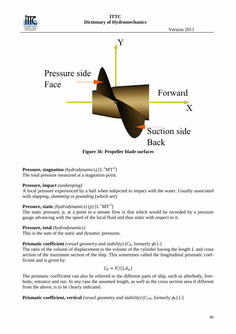
ITTC Dictionary of Hydromechanics
Version 2011
86
Figure 36: Propeller blade surfaces
Pressure, stagnation (hydrodynamics) [L-1MT-2] The total pressure measured at a stagnation point.
Pressure, impact (seakeeping) A local pressure experienced by a hull when subjected to impact with the water. Usually associated with slapping, slamming or pounding (which see)
Pressure, static (hydrodynamics) (p) [L-1MT-2] The static pressure, p, at a point in a stream flow is that which would be recorded by a pressure gauge advancing with the speed of the local fluid and thus static with respect to it.
Pressure, total (hydrodynamics) This is the sum of the static and dynamic pressures.
Prismatic coefficient (vessel geometry and stability) (CP, formerly φ) [-] The ratio of the volume of displacement to the volume of the cylinder having the length L and cross section of the maximum section of the ship. This sometimes called the longitudinal prismatic coef-ficient and is given by:
𝐶P = 𝛻/(𝐿𝐴𝑋) The prismatic coefficient can also be referred to the different parts of ship, such as afterbody, fore-body, entrance and run. In any case the assumed length, as well as the cross section area if different from the above, is to be clearly indicated.
Prismatic coefficient, vertical (vessel geometry and stability) (CVP, formerly φV) [-]
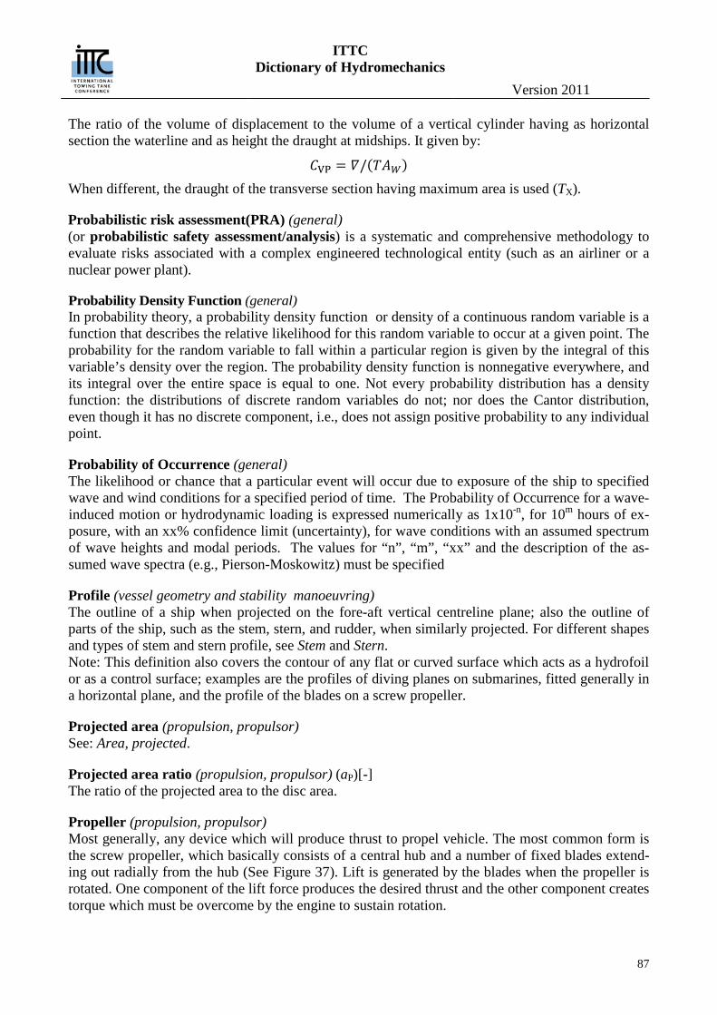
ITTC Dictionary of Hydromechanics
Version 2011
87
The ratio of the volume of displacement to the volume of a vertical cylinder having as horizontal section the waterline and as height the draught at midships. It given by:
𝐶VP = 𝛻/(𝑇𝐴𝑊) When different, the draught of the transverse section having maximum area is used (TX).
Probabilistic risk assessment(PRA) (general) (or probabilistic safety assessment/analysis) is a systematic and comprehensive methodology to evaluate risks associated with a complex engineered technological entity (such as an airliner or a nuclear power plant).
Probability Density Function (general) In probability theory, a probability density function or density of a continuous random variable is a function that describes the relative likelihood for this random variable to occur at a given point. The probability for the random variable to fall within a particular region is given by the integral of this variable’s density over the region. The probability density function is nonnegative everywhere, and its integral over the entire space is equal to one. Not every probability distribution has a density function: the distributions of discrete random variables do not; nor does the Cantor distribution, even though it has no discrete component, i.e., does not assign positive probability to any individual point.
Probability of Occurrence (general) The likelihood or chance that a particular event will occur due to exposure of the ship to specified wave and wind conditions for a specified period of time. The Probability of Occurrence for a wave-induced motion or hydrodynamic loading is expressed numerically as 1x10-n, for 10m hours of ex-posure, with an xx% confidence limit (uncertainty), for wave conditions with an assumed spectrum of wave heights and modal periods. The values for “n”, “m”, “xx” and the description of the as-sumed wave spectra (e.g., Pierson-Moskowitz) must be specified
Profile (vessel geometry and stability manoeuvring) The outline of a ship when projected on the fore-aft vertical centreline plane; also the outline of parts of the ship, such as the stem, stern, and rudder, when similarly projected. For different shapes and types of stem and stern profile, see Stem and Stern. Note: This definition also covers the contour of any flat or curved surface which acts as a hydrofoil or as a control surface; examples are the profiles of diving planes on submarines, fitted generally in a horizontal plane, and the profile of the blades on a screw propeller.
Projected area (propulsion, propulsor) See: Area, projected.
Projected area ratio (propulsion, propulsor) (aP)[-] The ratio of the projected area to the disc area.
Propeller (propulsion, propulsor) Most generally, any device which will produce thrust to propel vehicle. The most common form is the screw propeller, which basically consists of a central hub and a number of fixed blades extend-ing out radially from the hub (See Figure 37). Lift is generated by the blades when the propeller is rotated. One component of the lift force produces the desired thrust and the other component creates torque which must be overcome by the engine to sustain rotation.
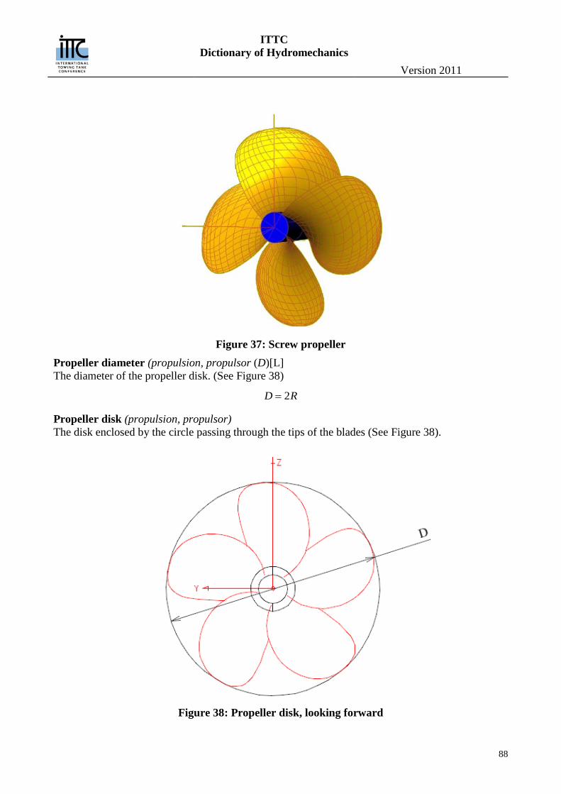
ITTC Dictionary of Hydromechanics
Version 2011
88
Figure 37: Screw propeller
Propeller diameter (propulsion, propulsor (D)[L] The diameter of the propeller disk. (See Figure 38)
2D R=
Propeller disk (propulsion, propulsor) The disk enclosed by the circle passing through the tips of the blades (See Figure 38).
Figure 38: Propeller disk, looking forward
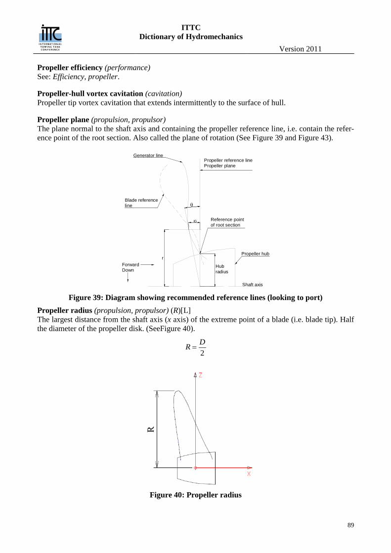
ITTC Dictionary of Hydromechanics
Version 2011
89
Propeller efficiency (performance) See: Efficiency, propeller.
Propeller-hull vortex cavitation (cavitation) Propeller tip vortex cavitation that extends intermittently to the surface of hull.
Propeller plane (propulsion, propulsor) The plane normal to the shaft axis and containing the propeller reference line, i.e. contain the refer-ence point of the root section. Also called the plane of rotation (See Figure 39 and Figure 43).
Figure 39: Diagram showing recommended reference lines (looking to port)
Propeller radius (propulsion, propulsor) (R)[L] The largest distance from the shaft axis (x axis) of the extreme point of a blade (i.e. blade tip). Half the diameter of the propeller disk. (SeeFigure 40).
2DR =
Figure 40: Propeller radius
ForwardDown
Propeller hub
Shaft axis
Propeller reference linePropeller plane
Generator line
Blade referenceline θ
iG
r
Hubradius
Reference pointof root section
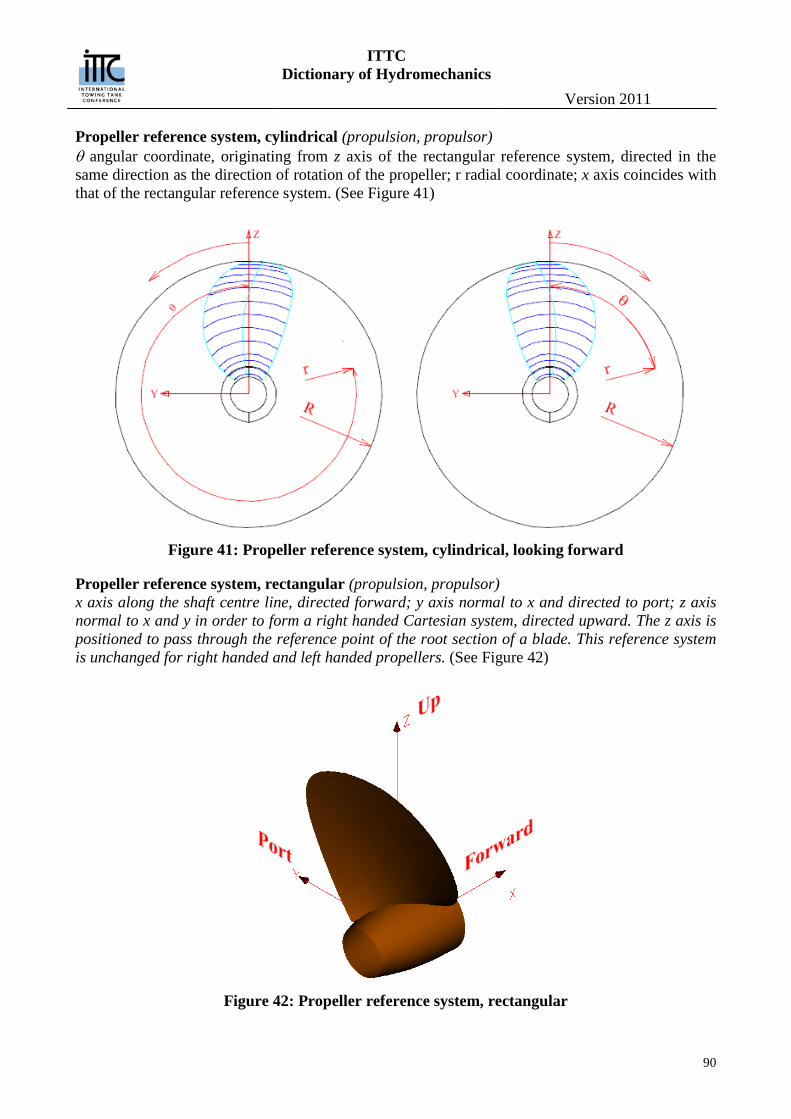
ITTC Dictionary of Hydromechanics
Version 2011
90
Propeller reference system, cylindrical (propulsion, propulsor) θ angular coordinate, originating from z axis of the rectangular reference system, directed in the same direction as the direction of rotation of the propeller; r radial coordinate; x axis coincides with that of the rectangular reference system. (See Figure 41)
Figure 41: Propeller reference system, cylindrical, looking forward
Propeller reference system, rectangular (propulsion, propulsor) x axis along the shaft centre line, directed forward; y axis normal to x and directed to port; z axis normal to x and y in order to form a right handed Cartesian system, directed upward. The z axis is positioned to pass through the reference point of the root section of a blade. This reference system is unchanged for right handed and left handed propellers. (See Figure 42)
Figure 42: Propeller reference system, rectangular
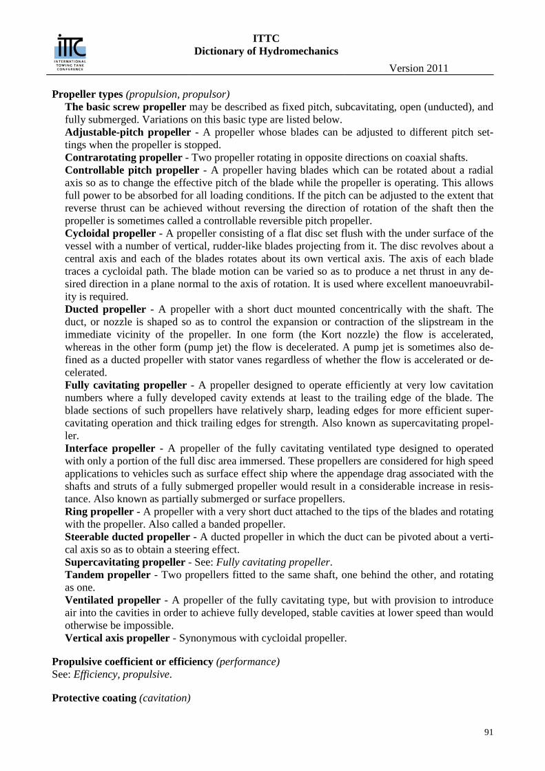
ITTC Dictionary of Hydromechanics
Version 2011
91
Propeller types (propulsion, propulsor) The basic screw propeller may be described as fixed pitch, subcavitating, open (unducted), and fully submerged. Variations on this basic type are listed below. Adjustable-pitch propeller - A propeller whose blades can be adjusted to different pitch set-tings when the propeller is stopped. Contrarotating propeller - Two propeller rotating in opposite directions on coaxial shafts. Controllable pitch propeller - A propeller having blades which can be rotated about a radial axis so as to change the effective pitch of the blade while the propeller is operating. This allows full power to be absorbed for all loading conditions. If the pitch can be adjusted to the extent that reverse thrust can be achieved without reversing the direction of rotation of the shaft then the propeller is sometimes called a controllable reversible pitch propeller. Cycloidal propeller - A propeller consisting of a flat disc set flush with the under surface of the vessel with a number of vertical, rudder-like blades projecting from it. The disc revolves about a central axis and each of the blades rotates about its own vertical axis. The axis of each blade traces a cycloidal path. The blade motion can be varied so as to produce a net thrust in any de-sired direction in a plane normal to the axis of rotation. It is used where excellent manoeuvrabil-ity is required. Ducted propeller - A propeller with a short duct mounted concentrically with the shaft. The duct, or nozzle is shaped so as to control the expansion or contraction of the slipstream in the immediate vicinity of the propeller. In one form (the Kort nozzle) the flow is accelerated, whereas in the other form (pump jet) the flow is decelerated. A pump jet is sometimes also de-fined as a ducted propeller with stator vanes regardless of whether the flow is accelerated or de-celerated. Fully cavitating propeller - A propeller designed to operate efficiently at very low cavitation numbers where a fully developed cavity extends at least to the trailing edge of the blade. The blade sections of such propellers have relatively sharp, leading edges for more efficient super-cavitating operation and thick trailing edges for strength. Also known as supercavitating propel-ler. Interface propeller - A propeller of the fully cavitating ventilated type designed to operated with only a portion of the full disc area immersed. These propellers are considered for high speed applications to vehicles such as surface effect ship where the appendage drag associated with the shafts and struts of a fully submerged propeller would result in a considerable increase in resis-tance. Also known as partially submerged or surface propellers. Ring propeller - A propeller with a very short duct attached to the tips of the blades and rotating with the propeller. Also called a banded propeller. Steerable ducted propeller - A ducted propeller in which the duct can be pivoted about a verti-cal axis so as to obtain a steering effect. Supercavitating propeller - See: Fully cavitating propeller. Tandem propeller - Two propellers fitted to the same shaft, one behind the other, and rotating as one. Ventilated propeller - A propeller of the fully cavitating type, but with provision to introduce air into the cavities in order to achieve fully developed, stable cavities at lower speed than would otherwise be impossible. Vertical axis propeller - Synonymous with cycloidal propeller.
Propulsive coefficient or efficiency (performance) See: Efficiency, propulsive.
Protective coating (cavitation)
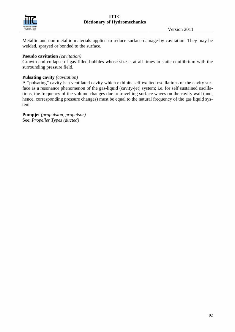
ITTC Dictionary of Hydromechanics
Version 2011
92
Metallic and non-metallic materials applied to reduce surface damage by cavitation. They may be welded, sprayed or bonded to the surface.
Pseudo cavitation (cavitation) Growth and collapse of gas filled bubbles whose size is at all times in static equilibrium with the surrounding pressure field.
Pulsating cavity (cavitation) A “pulsating” cavity is a ventilated cavity which exhibits self excited oscillations of the cavity sur-face as a resonance phenomenon of the gas-liquid (cavity-jet) system; i.e. for self sustained oscilla-tions, the frequency of the volume changes due to travelling surface waves on the cavity wall (and, hence, corresponding pressure changes) must be equal to the natural frequency of the gas liquid sys-tem.
Pumpjet (propulsion, propulsor) See: Propeller Types (ducted)

ITTC Dictionary of Hydromechanics
Version 2011
93
Q Quasi-propulsive coefficient or efficiency (performance) See: Efficiency, propulsive.
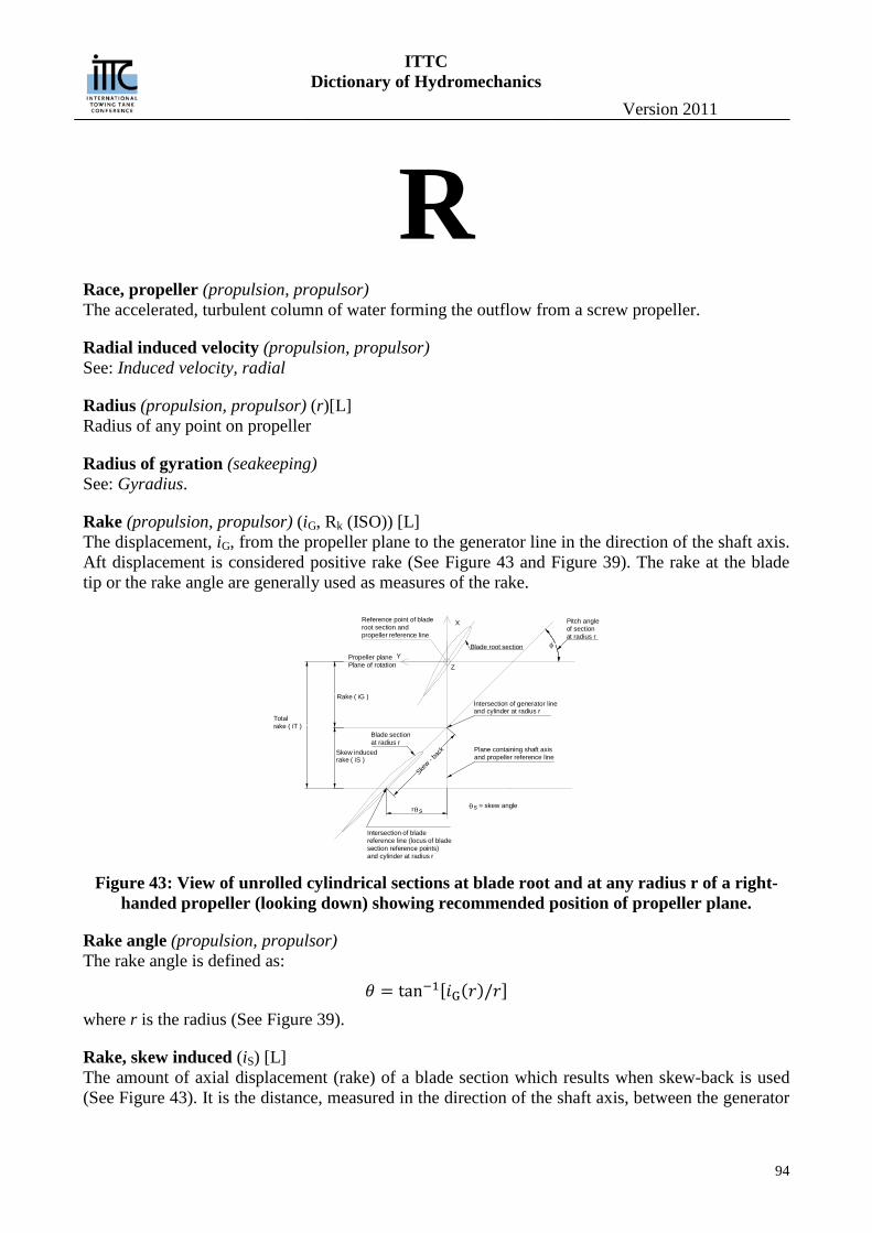
ITTC Dictionary of Hydromechanics
Version 2011
94
R Race, propeller (propulsion, propulsor) The accelerated, turbulent column of water forming the outflow from a screw propeller.
Radial induced velocity (propulsion, propulsor) See: Induced velocity, radial
Radius (propulsion, propulsor) (r)[L] Radius of any point on propeller
Radius of gyration (seakeeping) See: Gyradius.
Rake (propulsion, propulsor) (iG, Rk (ISO)) [L] The displacement, iG, from the propeller plane to the generator line in the direction of the shaft axis. Aft displacement is considered positive rake (See Figure 43 and Figure 39). The rake at the blade tip or the rake angle are generally used as measures of the rake.
Figure 43: View of unrolled cylindrical sections at blade root and at any radius r of a right-
handed propeller (looking down) showing recommended position of propeller plane.
Rake angle (propulsion, propulsor) The rake angle is defined as:
𝜃 = tan−1[𝑖G(𝑟)/𝑟] where r is the radius (See Figure 39).
Rake, skew induced (iS) [L] The amount of axial displacement (rake) of a blade section which results when skew-back is used (See Figure 43). It is the distance, measured in the direction of the shaft axis, between the generator
Z
Totalrake ( iT )
Skew inducedrake ( iS )
Blade sectionat radius r
Rake ( iG )
Propeller planePlane of rotation
Intersection of bladereference line (locus of bladesection reference points)and cylinder at radius r
θsr
Plane containing shaft axisand propeller reference line
φ
Pitch angleof sectionat radius r
Reference point of bladeroot section andpropeller reference line
Blade root section
Intersection of generator lineand cylinder at radius r
Skew - b
ack
Y
X
= skew anglesθ
ITTC Dictionary of Hydromechanics
Version 2011
95
line and the blade reference line and is given by: 𝑟𝜃S𝑡𝑎𝑛𝜑, where r is the local radius, θS is the lo-cal skew angle, and ϕ is the local pitch angle. It is positive when the generator line is forward of the blade reference line.
Rake total (propulsion, propulsor) (iT) [L] The sum of the rake and skew-induced rake (See Figure 43)
Raked Keel (vessel geometry and stability) See: Keel and Trim.
Ram bulb or bow (vessel geometry and stability) See: Bulb and Stem
Randomness (general) Is a lack of order, purpose, cause, or predictability in non-scientific parlance. A random process is a repeating process whose outcomes follow no describable deterministic pattern, but follow a proba-bility distribution.
Random process or Stochastic process Is the counterpart to a deterministic process (or deterministic system) in probability theory. Instead of dealing only with one possible 'reality' of how the process might evolve under time (as is the case, for example, for solutions of an ordinary differential equation), in a stochastic or random process there is some indeterminacy in its future evolution described by probability distributions. This means that even if the initial condition (or starting point) is known, there are many possibilities the process might go to, but some paths are more probable and others less.
Continuous Random Process — is one in which random variables which are functions of time can assume can assume any value within a specified range of possible values.
Discrete Random Process — is one in which the random variables can assume only certain specified values.
Ergodic Random Process — represents a stationary random process that possesses the property that almost every member of the ensemble exhibits the same statistical behavior that the whole ensem-ble has. Thus it is possible to determine this statistical behavior by examining only one typical sample function. Such processes are said to be ergodic and the mean values and moments can be determined by time averages as well as by ensemble averages.
Gaussian Random Process — .a Gaussian random process with a normal density function is one of the few for which it is possible to write a joint probability density function for any number of ran-dom variables. It is also the only one for which a complete statistical analysis can be carried through in either the linear or nonlinear situations. (expand)
Non-Stationary Random Process: — includes all random processes which so not meet the require-ments for stationarity as defined below. Unless further restrictions are imposed, the properties of a non-stationary random process are generally time-varying functions which can be determined only by performing instantaneous averages over the ensemble of sample functions forming the process. In practice, it is often not feasible to obtain a sufficient number of sample records to permit the ac-curate measurement of properties by ensemble averaging. (Bendat and Piersol, 2010, p417-) See also Wavelet analysis
Pseudo random process — a process that appears random but is not. Pseudorandom sequences typically exhibit statistical randomness while being generated by an entirely deterministic causal process. Such a process is easier to produce than a genuine random one, and has the benefit that it can be used again and again to produce exactly the same numbers, useful for
ITTC Dictionary of Hydromechanics
Version 2011
96
testing and fixing software. Stationary Random Process — If all marginal and joint density functions of the process do not de-
pend upon the choice of time origin, the process is said to be stationary. A process for which the mean variances, covariance functions and probability densities are independent of time transla-tions, i.e. Fourier transform pairs are well defined.
Rate of weight loss (cavitation) The primary criterion for cavitation erosion. The weight loss per unit time from a test specimen.
Ratio, aspect (manoeuvring) (Λ)[-] The ratio between the span of a hydrofoil, measured at right angles to the liquid flow, to the chord c of the hydrofoil, in the direction of flow. When the chord varies in length across the span, the aspect ratio is the span b divided by the mean chord c obtained generally dividing the hydrofoil projected area AP into the square of the span b, i.e. b2/ AP
Ratio, fineness, of a body (vessel geometry and stability) The ratio of the length L to the maximum diameter D of a body of revolution, or to the maximum breadth in other bodies.
Ratio, slenderness, of a ship (vessel geometry and stability) (MC) [-] See: Length coefficient of Froude.
Ratio, slip (performance) See: Slip ratio.
Rayleigh Distribution (general) Is a continuous probability distribution. It can arise when a two-dimensional vector (e.g. stationary irregular wave height and direction) has elements that are normally distributed, (wave elevation) are uncorrelated, and have equal variance. The vector’s magnitude (e.g. wave height) will then have a Rayleigh distribution. The distribution can also arise in the case of random complex numbers whose real and imaginary components are i.i.d. Gaussian. In that case, the modulus of the complex number is Rayleigh-distributed.
Rectified diffusion (cavitation) Term applied to the net mass transport into a bubble of gas dissolved in a saturated liquid when the liquid is subjected to an oscillating pressure field.
Re-entrant jets (cavitation) The re-entrant (upstream) flow at the trailing edge of steady (quasi-steady) cavities. Also, the re-entrant flow associated with the closure of non stationary cavities formed about missiles entering a water surface.
Reference line, blade (propulsion, propulsor) The locus of the reference points of the blade sections (See Figure 39 and Figure 28). Sometimes used synonymously with generator line.
Reference line, propeller (propulsion, propulsor) The straight line, normal to the shaft axis, which passes through the reference point of the root sec-tion (See Figure 39 and Figure 28). It lies in the plane containing the shaft axis and the generator line.
ITTC Dictionary of Hydromechanics
Version 2011
97
Reference point, blade section (propulsion, propulsor) The point on the pitch helix to which the blade section offsets are referred. It usually the mid-point of the chord line. The point of maximum thickness and the location of the spindle axis for control-lable pitch propeller, as well as other points, have also been used as blade section reference points. (See Figure 15)
Relative mass or weight (general), (γ) [-] The ratio of density of any substance to the density of fresh water at 4° Centigrade. In English speaking countries the concept expressed is called Specific gravity.
Relative rotative efficiency (performance) See: Efficiency, relative rotative.
Relative wind (performance) See: Wind, relative.
Reliable (general) suitable or fit to be relied upon, trustworthy, worthy of full confidence, dependable. Campbell and Stanley (1963) have addressed the approaches that can be used to establish the validity of engineer-ing analytical methods and processes.
Reliable Method (general) is one that yields valid and consistent results upon repeated use. A reliable method is suitable for its intended purposes. Reliability is established through multiple applications in prototype condi-tions by independent and qualified users representative of those that will use the method in practice.
Resistance (resistance) (R) [LMT-2] The fluid force acting on a moving body in such a way as to oppose its motion; the component of the fluid forces acting parallel to the axis of motion of a body. Resistance is the preferred term in ship hydrodynamics, while drag is generally used in aerodynamics and for submerged bodies. Total resistance is denoted by RT and various (not mutually exclusive) components of resistance are de-fined below. See also Drag.
Resistance, appendages (performance) (RAP) [LMT-2] The increase in resistance relative to that of the naked, or bare hull resistance, caused by append-ages such as bilge keels, rudders, bossings, struts, etc.
Resistance augment fraction (performance) (a) [-] The thrust T required to propel a model or ship at speed V is greater than the resistance RT of the hull when towed at the same speed. The increase TT R is called the augment of resistance, and the resistance augment fraction is:
T
T
T Ra
R
𝑇 = (1 + 𝑎)/𝑅T
Resistance coefficient (resistance) (CF, CR, CS, CT, CV, CW, etc.)[-] The non dimensional ratio of any specific component of resistance per unit area, to the dynamic pressure far ahead of the body.
ITTC Dictionary of Hydromechanics
Version 2011
98
Resistance coefficient, incremental, for model-ship correlation (performance) (CA) [-] The model-ship correlation allowance RA (which see) expressed in coefficient form:
𝐶A =𝑅A
12𝜌𝑉2𝑆
where ρ is the water density, V speed and S wetted surface.
Resistance coefficient, wind (performance) (CAA) [-] The ratio between the air or wind resistance on a ship or body RAA, and the force corresponding to the dynamic pressure times a specified area. It is customary to expressed it as :
𝐶AA =𝑅AA
12𝜌𝑉𝑅
2𝑆
Where A is the appropriate above water area of the ship, VR the relative wind velocity (which see) and ρ the air density.
Resistance, frictional (resistance) (RF) [LMT-2] The component of resistance obtained by integrating the tangential stresses over the surface of a body, in the direction of motion.
Resistance, frictional specific (resistance) (CF) [-] An alternative name for the coefficient of frictional resistance, in which the reference area is taken to be the wetted area under consideration.
Resistance, pressure (resistance) (RP) [LMT-2] The component of resistance obtained by integrating the normal stresses over the surface of a body in the direction of motion.
Resistance, residuary (resistance) (RR) [LMT-2] A quantity obtained by subtracting from the total resistance of a hull, a calculated friction resistance obtained by any specific formulation.
Resistance, roughness (performance) (RAR) [LMT-2] The increase in resistance relative to the resistance of a hydraulically smooth hull due to the effect of roughness. The hull roughness may be of different types such as:
Structural roughness caused by method of shell construction, waviness of plating, scoops, valve openings etc. Paint roughness depending on the type of paint as well as how it is applied. Corrosion roughness due to breakdown of the paint film and corrosion of the shell plating. Fouling roughness caused by marine organisms depositing shell, grass etc.
Resistance, spray (resistance) (RS) [LMT-2] The component of resistance associated with the expenditure of energy in generating spray.
Resistance, still air (performance) See: Resistance, wind.
Resistance in waves, mean increase in (seakeeping, performance) (RAW) [LMT-2]
ITTC Dictionary of Hydromechanics
Version 2011
99
The mean increase in resistance in wind and waves as compared with the still water resistance at the same speed.
Resistance, wave pattern (resistance) (RWP) [LMT-2] A resistance component deduced from measurements of wave elevations remote from ship or model where it is assumed that the sub surface velocity field, and hence the momentum of the fluid, can be related to the wave pattern by means of linearised theory . The resistance so deduced does not in-clude wavebreaking resistance.
Resistance, wavebreaking (resistance) (RWB) [LMT-2] A resistance component associated with the break down of the ship bow wave.
Resistance, wavemaking (resistance) (RW) [LMT-2] The component of resistance associated with the expenditure of energy in generating gravity waves.
Resistance, wind (performance) (RAA) [LMT-2] The fore and aft component of the resistance of above water form of a ship due to its motion rela-tive to still air or wind. When there is no natural wind, this is called the still air resistance. See also: Resistance coefficient, wind.
Resistance, viscous (resistance) (RV) [LMT-2] The component of resistance associated with the expenditure of energy in viscous effects.
Resistance, viscous pressure (resistance) (RPV) [LMT-2] The component of resistance obtained by integrating the components of the normal stresses due to viscosity and turbulence. This quantity cannot be directly measured except for a fully submerged body when it is equal to the pressure resistance RP.
Resonance (seakeeping) The dynamical condition of a simple, uncoupled system where the excitation frequency is equal to the natural frequency. Note: In a coupled system, the dynamic condition where the excitation frequency corresponds to the
frequency of maximum response to unit exciting force over a range of frequencies.
Response (seakeeping) The reaction of the system to an excitation.
Response amplitude operator (seakeeping) The square of the ratio of response amplitude to excitation amplitude of a forced harmonic motion applied to a linear system, as a function of frequency.
Response function (seakeeping) A complex function of which the modulus is equal to the response amplitude operator and the ar-gument is equal to the phase response operator.
Restricted water (performance) See: Water, restricted.
Revolutions, rate of, mean in waves (seakeeping, performance) (nAW) [ T-1]
ITTC Dictionary of Hydromechanics
Version 2011
100
The mean absolute increase in rate of revolutions (usually per minute), as compared with those in smooth water, necessary to maintain speed in wind and waves.
Reynolds number (hydrodynamics) (Re) [-] A dimensionless parameter expressing the condition of dynamical similarity for flow systems influ-enced by viscosity and inertia alone. For equal values of Reynolds number and the same orientation to the flow, the specific resistance coefficients of all geometrically similar smooth surfaces are iden-tical as long as the uninfluenced speed field are similar and the flow is influenced by viscosity and inertia alone. It is given by:
𝑅𝑒 =𝑉𝐿𝜌𝜇
=𝑉𝐿𝜈
The length term L is usually the length of the surface, but the distance from the leading edge of the surface to a specific point, the diameter of a body, or the thickness of the boundary layer are some-times used as length terms.
Right handed propeller (propulsion, propulsor) A propeller which rotates in the clockwise direction when viewed from astern.
Righting Arm Coefficient (vessel geometry and stability) (CGZ) [-] The dimensionless horizontal distance between the center of gravity and the vertical line of action through the center of buoyancy at any angle of heel. 1 3
GZC GZ ∇=
Risk (general) A state of uncertainty where some possible outcomes have an undesired effect or significant loss.
Risk, Measurement of (general) A set of measured uncertainties where some possible outcomes are losses (failures), and the magni-tudes of those losses - this also includes loss functions over continuous variables.
Roll angle (manoeuvring, seakeeping) (φ) [ - ] The angle measured about the longitudinal body axis, between the instantaneous position of a ship when rolling (which see) and its normal upright position. (Positive starboard down).
Rolling (manoeuvring, seakeeping) The angular component of the oscillatory motion of a hull about a longitudinal axis.
Root (propulsion, propulsor) The part of the propeller blade adjacent to the propeller hub.
Root cavitation (cavitation) Cavitation in the low-pressure region of the blade roots on a marine propeller.
Rough surface (performance) See: Surface, rough.
Roughness allowance (performance) (∆CF) [-]
ITTC Dictionary of Hydromechanics
Version 2011
101
Now obsolescent, See: Resistance coefficient, incremental for model-ship correlation (CA)
Roughness, equivalent sand (performance) (KS) [L] Equivalent sand roughness is used as a convenient measure of the roughness of a surface and is de-termined by equating the frictional resistance of a surface of random roughness with that of a flat plate completely covered with sand grains of a sensibly uniform size as in Nikuradse’s experiments. It is the average diameter of the Nikuradse sand grains.
Roughness, height or magnitude (performance) (k) [L] A length dimension expressing the height of a roughness element on a surface exposed to liquid flow. It is often expressed as some form of average such as root mean square or mean apparent am-plitude.
Roughness, resistance (performance) See: Resistance, roughness.
Rudder (manoeuvring) A control surface, which by its action or movement, controls the steering or the turning of a ship in horizontal plane. Specifically, hinged or movable control-surface appendage in the form of a hydro-foil, placed either at the bow or at the stern of a ship, or at both ends, to apply a turning moment to the ship.
Rudder (propulsion, propulsor) See Ship Geometry section.
Rudder, active (propulsion, propulsor) A propulsion device installed in the rudder for ship manoeuvring at low or zero speed.
Rudder angle ((performance, manoeuvring) (δR) [-] The angular displacement of the rudder about its stock relative to the neutral position and measured in a plane normal to the stock. Positive when turning in the positive sense of rotation of the ship, re-gardless of the effect this angle may have on the ship. See also: Control surface angle.
Rudder angle, ordered (manoeuvring, performance) (δRO) [-] The ordered angle set on the steering control apparatus. This may differ from the rudder angle δR, depending on the lag and lost motion in the steering control and gear.
Rudder area, total (manoeuvring) (AR, ART) [L2] The total lateral area of the rudder (including fixed and movable parts) measured in the reference plane (generally the plane of symmetry). See also: Control surface area.
Rudder area, fixed (manoeuvring) (AX) [L2] The lateral area of the sole fixed part of the rudder. See also: Control surface area.
Rudder area, movable (manoeuvring) (ARmov) [L2] The lateral area of the sole movable part of the rudder. See also: Control surface area.
Rudder directions (manoeuvring)
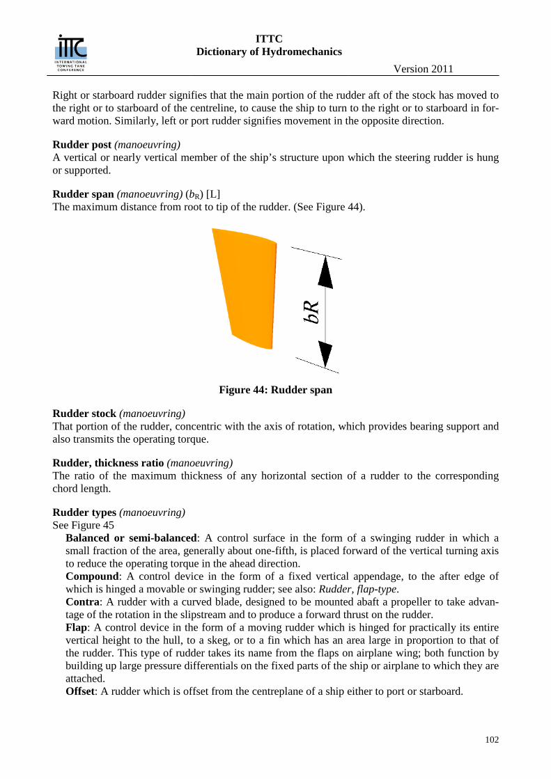
ITTC Dictionary of Hydromechanics
Version 2011
102
Right or starboard rudder signifies that the main portion of the rudder aft of the stock has moved to the right or to starboard of the centreline, to cause the ship to turn to the right or to starboard in for-ward motion. Similarly, left or port rudder signifies movement in the opposite direction.
Rudder post (manoeuvring) A vertical or nearly vertical member of the ship’s structure upon which the steering rudder is hung or supported.
Rudder span (manoeuvring) (bR) [L] The maximum distance from root to tip of the rudder. (See Figure 44).
Figure 44: Rudder span
Rudder stock (manoeuvring) That portion of the rudder, concentric with the axis of rotation, which provides bearing support and also transmits the operating torque.
Rudder, thickness ratio (manoeuvring) The ratio of the maximum thickness of any horizontal section of a rudder to the corresponding chord length.
Rudder types (manoeuvring) See Figure 45
Balanced or semi-balanced: A control surface in the form of a swinging rudder in which a small fraction of the area, generally about one-fifth, is placed forward of the vertical turning axis to reduce the operating torque in the ahead direction. Compound: A control device in the form of a fixed vertical appendage, to the after edge of which is hinged a movable or swinging rudder; see also: Rudder, flap-type. Contra: A rudder with a curved blade, designed to be mounted abaft a propeller to take advan-tage of the rotation in the slipstream and to produce a forward thrust on the rudder. Flap: A control device in the form of a moving rudder which is hinged for practically its entire vertical height to the hull, to a skeg, or to a fin which has an area large in proportion to that of the rudder. This type of rudder takes its name from the flaps on airplane wing; both function by building up large pressure differentials on the fixed parts of the ship or airplane to which they are attached. Offset: A rudder which is offset from the centreplane of a ship either to port or starboard.
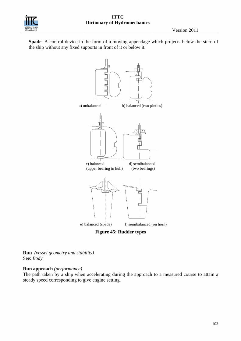
ITTC Dictionary of Hydromechanics
Version 2011
103
Spade: A control device in the form of a moving appendage which projects below the stern of the ship without any fixed supports in front of it or below it.
a) unbalanced b) balanced (two pintles)
c) balanced d) semibalanced (upper bearing in hull) (two bearings)
e) balanced (spade) f) semibalanced (on horn)
Figure 45: Rudder types
Run (vessel geometry and stability) See: Body
Run approach (performance) The path taken by a ship when accelerating during the approach to a measured course to attain a steady speed corresponding to give engine setting.
ITTC Dictionary of Hydromechanics
Version 2011
104
S Salt water, standard (performance) See: Water, standard salt.
Scale effect (performance) The change in any force, moment or pressure coefficients, flow pattern, or the like, due to a change in absolute size between geometrically similar models, bodies or ships. These variations in per-formance due to differences in absolute size arise from the inability to satisfy simultaneously all the relevant laws of dynamical similarity (e.g. gravitational, viscous and surface tension).
Scenario Analysis (vessel geometry and stability) Is a process of analyzing possible future events by considering alternative possible outcomes (sce-narios). The analysis is designed to allow improved decision-making by allowing more complete consideration of outcomes and their implications. For complex systems with unknown joint proba-bilities, useful scenarios can be classified into pessimistic, optimistic and likely scenarios.
Scoop (vessel geometry and stability) An opening in the surface of the underwater body of a ship, which may or may not be fitted with a projection extending beyond that surface, designed for catching and taking water into a ship.
Screening effect (cavitation) Effect associated with the “screening” of nuclei by the pressure gradient about the body to which the nuclei are being convected, thus determining which nuclei will be repelled from and which nu-clei will be swept into regions where the pressure are such as to enable cavitation inception to take place.
Screw propeller (propulsion, propulsor) See: Propeller.
Sea direction (seakeeping) Beam sea - A condition in which a ship and waves, or the predominant wave components, ad-vance at right angles, or nearly so. Bow sea - A condition in which a ship and the waves, or the predominant wave components, ad-vance at oblique angles. This condition covers the direction between a head sea and beam sea. Following sea - A condition in which ship and the waves, or predominant wave components, ad-vance in the same, or nearly the same direction. Head sea - A condition in which a ship and the waves, or the predominant components, advance in opposite, or nearly opposite directions. Quartering sea - A condition in which a ship and the waves, or the predominant wave compo-nents, advance at oblique angles. This condition covers the directions between a beam sea and a following sea.
Seakeeping (seakeeping)
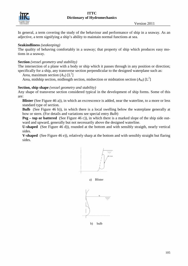
ITTC Dictionary of Hydromechanics
Version 2011
105
In general, a term covering the study of the behaviour and performance of ship in a seaway. As an adjective, a term signifying a ship’s ability to maintain normal functions at sea.
Seakindliness (seakeeping) The quality of behaving comfortably in a seaway; that property of ship which produces easy mo-tions in a seaway.
Section (vessel geometry and stability) The intersection of a plane with a body or ship which it passes through in any position or direction; specifically for a ship, any transverse section perpendicular to the designed waterplane such as:
Area, maximum section (AX) [L2] Area, midship section, midlength section, midsection or midstation section (AM) [L2]
Section, ship shape (vessel geometry and stability) Any shape of transverse section considered typical in the development of ship forms. Some of this are:
Blister (See Figure 46 a)), in which an excrescence is added, near the waterline, to a more or less standard type of section. Bulb (See Figure 46 b)), in which there is a local swelling below the waterplane generally at bow or stern. (For details and variations see special entry Bulb) Peg – top or battered (See Figure 46 c)), in which there is a marked slope of the ship side out-ward and upward, generally but not necessarily above the designed waterline. U-shaped (See Figure 46 d)), rounded at the bottom and with sensibly straigth, nearly vertical sides. V-shaped (See Figure 46 e)), relatively sharp at the bottom and with sensibly straight but flaring sides.
a) Blister
b) bulb
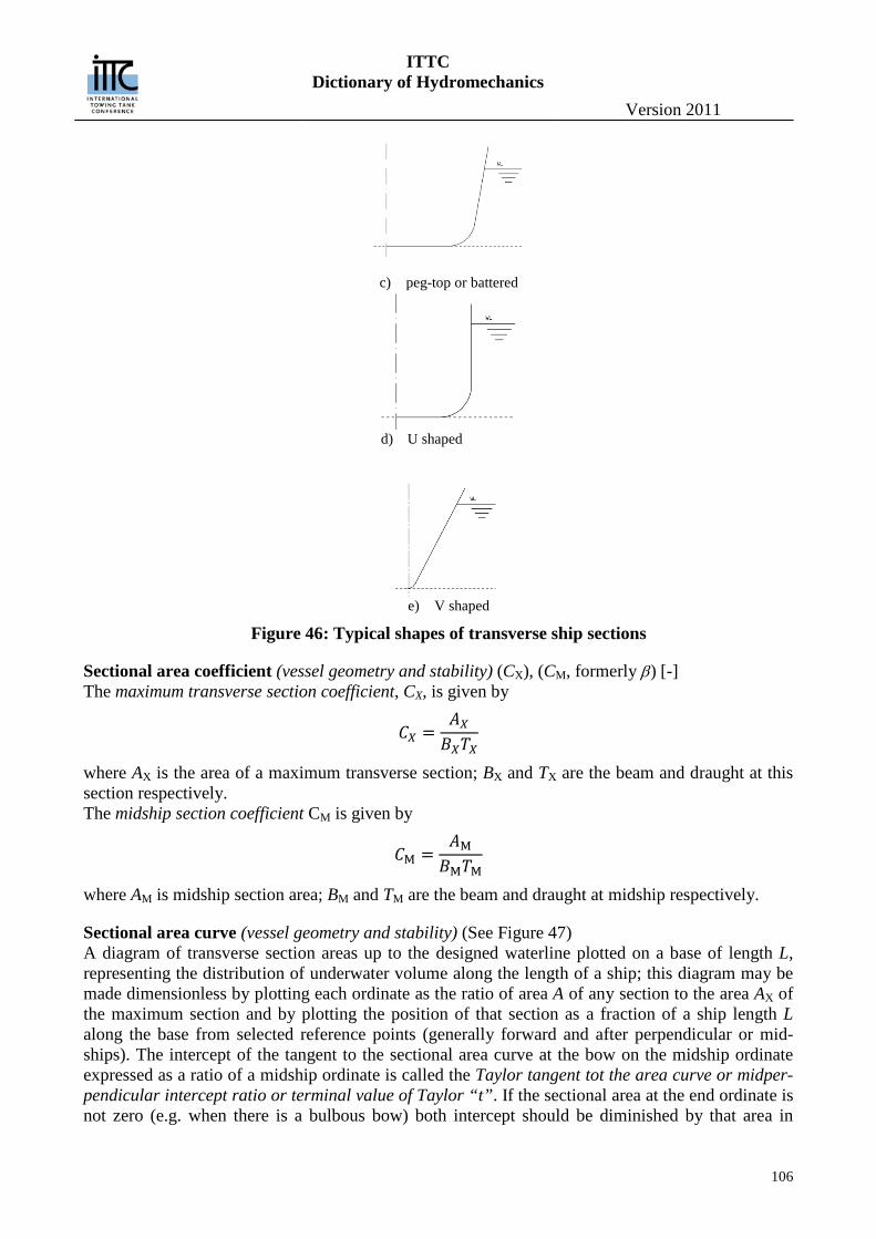
ITTC Dictionary of Hydromechanics
Version 2011
106
c) peg-top or battered
d) U shaped
e) V shaped
Figure 46: Typical shapes of transverse ship sections
Sectional area coefficient (vessel geometry and stability) (CX), (CM, formerly β) [-] The maximum transverse section coefficient, CX, is given by
𝐶𝑋 =𝐴𝑋𝐵𝑋𝑇𝑋
where AX is the area of a maximum transverse section; BX and TX are the beam and draught at this section respectively. The midship section coefficient CM is given by
𝐶M =𝐴M𝐵M𝑇M
where AM is midship section area; BM and TM are the beam and draught at midship respectively.
Sectional area curve (vessel geometry and stability) (See Figure 47) A diagram of transverse section areas up to the designed waterline plotted on a base of length L, representing the distribution of underwater volume along the length of a ship; this diagram may be made dimensionless by plotting each ordinate as the ratio of area A of any section to the area AX of the maximum section and by plotting the position of that section as a fraction of a ship length L along the base from selected reference points (generally forward and after perpendicular or mid-ships). The intercept of the tangent to the sectional area curve at the bow on the midship ordinate expressed as a ratio of a midship ordinate is called the Taylor tangent tot the area curve or midper-pendicular intercept ratio or terminal value of Taylor “t”. If the sectional area at the end ordinate is not zero (e.g. when there is a bulbous bow) both intercept should be diminished by that area in
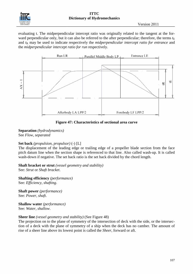
ITTC Dictionary of Hydromechanics
Version 2011
107
evaluating t. The midperpendicular intercept ratio was originally related to the tangent at the for-ward perpendicular only, but it can also be referred to the after perpendicular; therefore, the terms tE and tR may be used to indicate respectively the midperpendicular intercept ratio for entrance and the midperpendicular intercept ratio for run respectively.
Figure 47: Characteristics of sectional area curve
Separation (hydrodynamics) See Flow, separated
Set back (propulsion, propulsor) (-) [L] The displacement of the leading edge or trailing edge of a propeller blade section from the face pitch datum line when the section shape is referenced to that line. Also called wash-up. It is called wash-down if negative. The set back ratio is the set back divided by the chord length.
Shaft bracket or strut (vessel geometry and stability) See: Strut or Shaft bracket.
Shafting efficiency (performance) See: Efficiency, shafting.
Shaft power (performance) See: Power, shaft.
Shallow water (performance) See: Water, shallow.
Sheer line (vessel geometry and stability) (See Figure 48) The projection on to the plane of symmetry of the intersection of deck with the side, or the intersec-tion of a deck with the plane of symmetry of a ship when the deck has no camber. The amount of rise of a sheer line above its lowest point is called the Sheer, forward or aft.
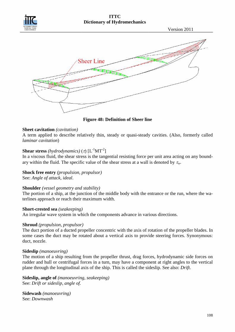
ITTC Dictionary of Hydromechanics
Version 2011
108
Figure 48: Definition of Sheer line
Sheet cavitation (cavitation) A term applied to describe relatively thin, steady or quasi-steady cavities. (Also, formerly called laminar cavitation)
Shear stress (hydrodynamics) (τ) [L-1MT-2] In a viscous fluid, the shear stress is the tangential resisting force per unit area acting on any bound-ary within the fluid. The specific value of the shear stress at a wall is denoted by τw.
Shock free entry (propulsion, propulsor) See: Angle of attack, ideal.
Shoulder (vessel geometry and stability) The portion of a ship, at the junction of the middle body with the entrance or the run, where the wa-terlines approach or reach their maximum width.
Short-crested sea (seakeeping) An irregular wave system in which the components advance in various directions.
Shroud (propulsion, propulsor) The duct portion of a ducted propeller concentric with the axis of rotation of the propeller blades. In some cases the duct may be rotated about a vertical axis to provide steering forces. Synonymous: duct, nozzle.
Sideslip (manoeuvring) The motion of a ship resulting from the propeller thrust, drag forces, hydrodynamic side forces on rudder and hull or centrifugal forces in a turn, may have a component at right angles to the vertical plane through the longitudinal axis of the ship. This is called the sideslip. See also: Drift.
Sideslip, angle of (manoeuvring, seakeeping) See: Drift or sideslip, angle of.
Sidewash (manoeuvring) See: Downwash
ITTC Dictionary of Hydromechanics
Version 2011
109
Significant wave height (seakeeping) See: Wave height, significant.
Simplified Stability Criteria (vessel geometry and stability) (NSCV) — a set of deemed-to-satisfy stability criteria that do not require the full analysis of stabili-ty using individual loading conditions to derive righting lever curves (GFZ curves). NOTES: 1. Simplified stability criteria are applied to enable the use of simplified test methods. 2. Simplified stability criteria are strictly limited in their application to avoid potential inaccura-
cies and erroneous conclusions as to a vessel’s stability characteristics.
Simplified Stability Test Methods (vessel geometry and stability) (NSCV) — test methods that, if properly applied, can provide a simplified and normally less expen-sive approach to the determination of stability characteristics of certain specified types of vessels. NOTES: 1. Simplified test methods are not suitable where comprehensive intact stability criteria apply. 2. Simplified test methods may involve stability proof testing where measurements are taken of
freeboards and angles of heel, or alternatively a practical inclining experiment for determining GFMO.
Sinkage (seakeeping) The steady state lowering of a ship’s position of flotation in the water; to be distinguished from heaving, which is an oscillatory motion.
Singing (propulsion, propulsor) Intense discrete frequency sound radiated from the propeller due to resonant vibrations of the blades. Generally thought to be due to the shedding of Karman vortices from the trailing edge of the blades at a resonant frequency of the blade vibration.
Sink (hydrodynamics) A point at which fluid is assumed to be withdrawn symmetrically from all directions. The velocity potential due to a sink has the same form as the potential due to a source, but the strength Q is nega-tive. See also Source.
Skeg (vessel geometry and stability, manoeuvring) The thin portion of the hull at the stern of a vessel immediately forward of or in the vicinity of the rudder. A skeg is usually of large lateral area compared to its transverse thickness, is provided for the support of a propeller shaft, for structural strength, for docking support, for protection when grounding or to increase the lateral area and give increased roll damping and course keeping ability to the hull or for other reasons. It is placed generally at the aft end, but not necessarily on the centre-line. (See Figure 49).
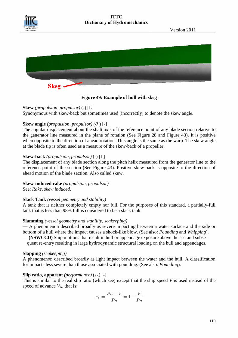
ITTC Dictionary of Hydromechanics
Version 2011
110
Figure 49: Example of hull with skeg
Skew (propulsion, propulsor) (-) [L] Synonymous with skew-back but sometimes used (incorrectly) to denote the skew angle.
Skew angle (propulsion, propulsor) (θS) [-] The angular displacement about the shaft axis of the reference point of any blade section relative to the generator line measured in the plane of rotation (See Figure 28 and Figure 43). It is positive when opposite to the direction of ahead rotation. This angle is the same as the warp. The skew angle at the blade tip is often used as a measure of the skew-back of a propeller.
Skew-back (propulsion, propulsor) (-) [L] The displacement of any blade section along the pitch helix measured from the generator line to the reference point of the section (See Figure 43). Positive skew-back is opposite to the direction of ahead motion of the blade section. Also called skew.
Skew-induced rake (propulsion, propulsor) See: Rake, skew induced.
Slack Tank (vessel geometry and stability) A tank that is neither completely empty nor full. For the purposes of this standard, a partially-full tank that is less than 98% full is considered to be a slack tank.
Slamming (vessel geometry and stability, seakeeping) — A phenomenon described broadly as severe impacting between a water surface and the side or bottom of a hull where the impact causes a shock-like blow. (See also: Pounding and Whipping). — (NSWCCD) Ship motions that result in hull or appendage exposure above the sea and subse-
quent re-entry resulting in large hydrodynamic structural loading on the hull and appendages.
Slapping (seakeeping) A phenomenon described broadly as light impact between the water and the hull. A classification for impacts less severe than those associated with pounding. (See also: Pounding).
Slip ratio, apparent (performance) (sA) [-] This is similar to the real slip ratio (which see) except that the ship speed V is used instead of the speed of advance VA, that is:
A 1Pn V V
sPn Pn
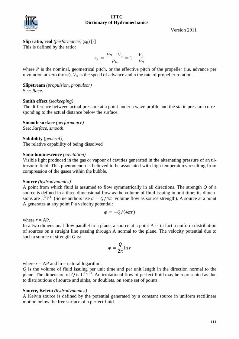
ITTC Dictionary of Hydromechanics
Version 2011
111
Slip ratio, real (performance) (sR) [-] This is defined by the ratio:
R 1A APn V Vs
Pn Pn
where P is the nominal, geometrical pitch, or the effective pitch of the propeller (i.e. advance per revolution at zero thrust), VA is the speed of advance and n the rate of propeller rotation.
Slipstream (propulsion, propulsor) See: Race.
Smith effect (seakeeping) The difference between actual pressure at a point under a wave profile and the static pressure corre-sponding to the actual distance below the surface.
Smooth surface (performance) See: Surface, smooth.
Solubility (general), The relative capability of being dissolved
Sono-luminescence (cavitation) Visible light produced in the gas or vapour of cavities generated in the alternating pressure of an ul-trasonic field. This phenomenon is believed to be associated with high temperatures resulting from compression of the gases within the bubble.
Source (hydrodynamics) A point from which fluid is assumed to flow symmetrically in all directions. The strength Q of a source is defined in a three dimensional flow as the volume of fluid issuing in unit time; its dimen-sions are L3T-1. (Some authors use 𝜎 = 𝑄 4𝜋⁄ volume flow as source strength). A source at a point A generates at any point P a velocity potential:
𝜙 = −𝑄 (4𝜋𝑟)⁄ where r = AP. In a two dimensional flow parallel to a plane, a source at a point A is in fact a uniform distribution of sources on a straight line passing through A normal to the plane. The velocity potential due to such a source of strength Q is:
𝜙 =𝑄
2𝜋ln 𝑟
where r = AP and ln = natural logarithm. Q is the volume of fluid issuing per unit time and per unit length in the direction normal to the plane. The dimension of Q is L2 T-1. An irrotational flow of perfect fluid may be represented as due to distributions of source and sinks, or doublets, on some set of points.
Source, Kelvin (hydrodynamics) A Kelvin source is defined by the potential generated by a constant source in uniform rectilinear motion below the free surface of a perfect fluid.
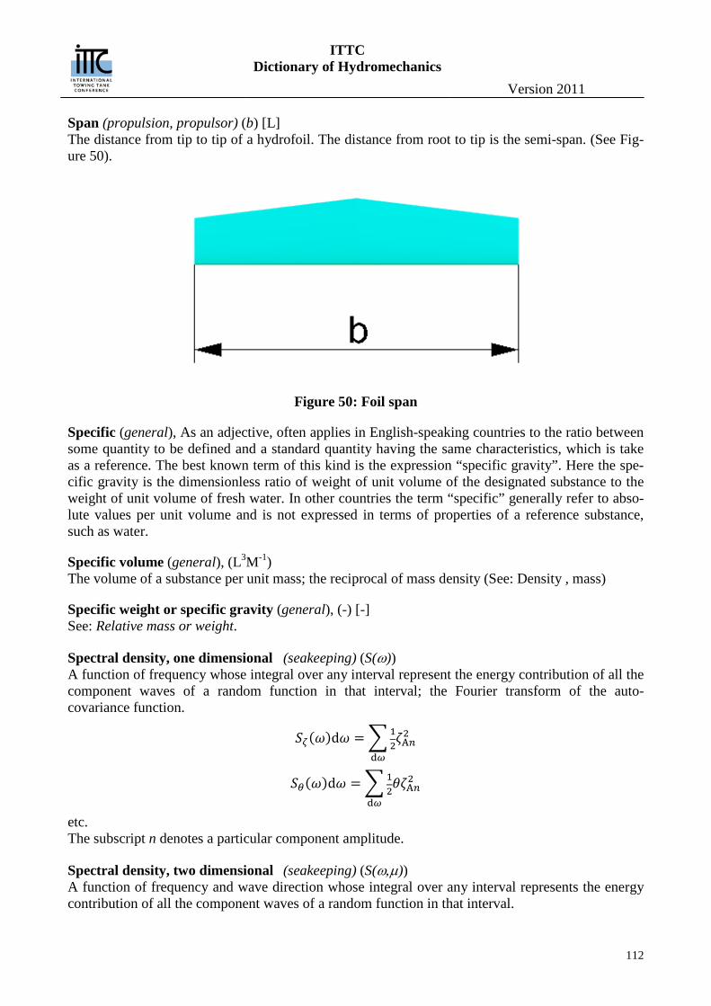
ITTC Dictionary of Hydromechanics
Version 2011
112
Span (propulsion, propulsor) (b) [L] The distance from tip to tip of a hydrofoil. The distance from root to tip is the semi-span. (See Fig-ure 50).
Figure 50: Foil span
Specific (general), As an adjective, often applies in English-speaking countries to the ratio between some quantity to be defined and a standard quantity having the same characteristics, which is take as a reference. The best known term of this kind is the expression “specific gravity”. Here the spe-cific gravity is the dimensionless ratio of weight of unit volume of the designated substance to the weight of unit volume of fresh water. In other countries the term “specific” generally refer to abso-lute values per unit volume and is not expressed in terms of properties of a reference substance, such as water.
Specific volume (general), (L3M-1) The volume of a substance per unit mass; the reciprocal of mass density (See: Density , mass)
Specific weight or specific gravity (general), (-) [-] See: Relative mass or weight.
Spectral density, one dimensional (seakeeping) (S(ω)) A function of frequency whose integral over any interval represent the energy contribution of all the component waves of a random function in that interval; the Fourier transform of the auto-covariance function.
𝑆𝜁(𝜔)d𝜔 = �12𝜁A𝑛
2
d𝜔
𝑆𝜃(𝜔)d𝜔 = �12𝜃𝜁A𝑛
2
d𝜔 etc. The subscript n denotes a particular component amplitude.
Spectral density, two dimensional (seakeeping) (S(ω,µ)) A function of frequency and wave direction whose integral over any interval represents the energy contribution of all the component waves of a random function in that interval.
ITTC Dictionary of Hydromechanics
Version 2011
113
Spectrum (seakeeping) Amplitude - A function of frequency whose integral over any interval represents the squared amplitude of a wave at the central frequency having the same energy as all the component waves in that interval. Co-spectrum - The real part of a cross-spectrum (which see). Cross-spectrum - A complex function of frequency expressing the mutual properties of two random functions; the Fourier transform of the cross-covariance function, The real part, or co-spectrum, indicates the relationship between in-phase frequency components; the imaginary part, or quadrature spectrum, indicates the relation between 90° out-of-phase frequency components. Quadrature spectrum - The imaginary part of a cross-spectrum.
Speed, approach (manoeuvring) The speed of a body or ship along the straight approach path, just prior to entry into a turn.
Speed, corresponding (performance) The speed of a ship VS related to that of a model VM, or vice-versa, according to Froude’s Law of comparison:
𝑉S = 𝑉M√𝜆
where λ is the scale factor.
Speed, ground (performance) The speed of a ship relative to the ground, that is the speed including the effects of tide and cur-rents. When the ship is moving through still water the ground speed id the same as the true water speed.
Speed, hump (resistance) (in high speed craft) [LT-1] The speed at which the resistance reaches a maximum before a planing craft enters the planing phase, or a hydrofoil craft enters the foilborne phase. (See Figure 51).
Figure 51: Resistance curve of a planing craft
ITTC Dictionary of Hydromechanics
Version 2011
114
Speed loss (performance) The decrease in speed, as compared with that in smooth water, caused directly by wind and waves at a constant setting of the main propulsion plant. Usually speed loss is determined at constant power (turbine plant) or constant torque (diesel plant).
Speed loss (seakeeping) The decrease in speed, as compared with that in smooth water, caused directly by wind and waves at a constant setting of the main propulsion plant. Usually speed loss is determined at constant power (turbine plant) or constant torque (diesel plant).
Speed of advance (propulsion, propulsor) (VA) [LT-1] The translational speed of the propeller in relation to the body of water into which it is advancing. See also: Performance Section.
Speed of advance of a propeller (performance) (VA) [LT-1] Speed of advance of a propeller in open water. When a propeller behind a ship or model is produc-ing the same thrust at the same rate of rotation as in open water the corresponding speed VA deter-mined from the open water propeller characteristic is termed the speed of advance of the propeller. This is usually less than the ship speed V. (See also: Wake fraction, effective). This is based on thrust identity. There is another corresponding speed based on torque identity.
Speed reduction (seakeeping) The decrease in speed, as compared with that in smooth water, caused mainly by reducing the set-ting of the main propulsion plant in order to minimise the adverse effects ion the ship of wind and waves. (performance) The decrease in speed, as compared with that in smooth water, caused mainly by reducing the setting of the main propulsion plant in order to minimise the adverse effects on the ship of wind and waves.
Speed, true water (performance) The speed of a ship relative to the surrounding water.
Spindle axis (propulsion, propulsor) The axis about which a controllable-pitch propeller blade is rotated to achieve a change in pitch.
Spindle torque (propulsion, propulsor) (QS) [ML2T-2]
The torque acting about the spindle axis of a controllable-pitch propeller blade resulting from the hydrodynamic and centrifugal forces exerted on the blade. This torque is positive if tends to rotate the blade toward a higher positive pitch.
Spindle torque, hydrodynamic (propulsion, propulsor) (QSH) [ML2T-2] The torque acting about the spindle axis of a controllable-pitch propeller blade resulting from the hydrodynamic forces exerted on the blade. This torque is positive if it tends to rotate the blade to-ward a higher positive pitch.
Spindle torque coefficient, centrifugal (propulsion, propulsor) (KSC) [-] The centrifugal spindle torque, QSC, expressed in coefficient form:
𝐾SC = 𝑄SC/(𝜌P𝑛2𝐷5)
ITTC Dictionary of Hydromechanics
Version 2011
115
where ρP is the mass density of the propeller blade material, n is the rate of propeller rotation, and D is the propeller diameter.
Spindle torque coefficient, hydrodynamic (propulsion, propulsor) (KSH) [-] The hydrodynamic spindle torque, QSH, expressed in coefficient form:
𝐾SH = 𝑄SH/(𝜌𝑛2𝐷5)
where ρ is the mass density of the fluid, n is the rate of propeller rotation, and D is the propeller di-ameter.
Spindle torque index, hydrodynamic (propulsion, propulsor) () [-] The hydrodynamic spindle torque, QSH, expressed in coefficient form:
𝑄SH/ �12𝜌[𝑉A2 + (0.7𝑛𝐷)2]� (𝜋𝐷3/4)
where ρ is the density of the fluid, VA is the speed of advance, n is the rate of propeller rotation, and D is the diameter. This form of the spindle torque coefficient is useful when presenting propeller spindle torque characteristics over a range of advance coefficient extending from zero (VA = 0) to infinity (n = 0). Usually presented as a function of
𝛽∗ = tan−1[𝑉A/(0.7 𝑛𝜋𝐷)]
Spoiler (manoeuvring) Any device ancillary to a hydrofoil or control surface or stabiliser to disturb the flow, in order to diminish the lift.
Spongy surface appearance (cavitation) Description of a surface badly damaged by cavitation in which erosion has taken place to a consid-erable depth and has the appearance of a sponge. This description is particularly characteristic of brittle materials and other materials after long exposure.
Spot cavitation (cavitation) A general term for narrow quasi-steady cavities attached to a surface.
Spray strip (vessel geometry and stability) A relatively narrow strip, of small cross-section, attached to the hull of a ship for the purpose of controlling or diverting spray.
Spread (vessel geometry and stability) (-) [L] The transverse horizontal distance between the centreplanes or the other designed plane or line of the two hulls of a catamaran or other multi-hulled craft.
Springing (seakeeping) The continuous ship-hull vibration induced by the non-impulsive hydrodynamic forces acting on the ship hull. In particular, the vibratory response of the ship hull girder to short waves with frequencies of encounter close to the lower structural modes of vibration of the ship. See also: Whipping.
Stabiliser (seakeeping) Equipment to reduce the rolling (or pitching) motions of a ship.
Stability (general, vessel geometry and stability),
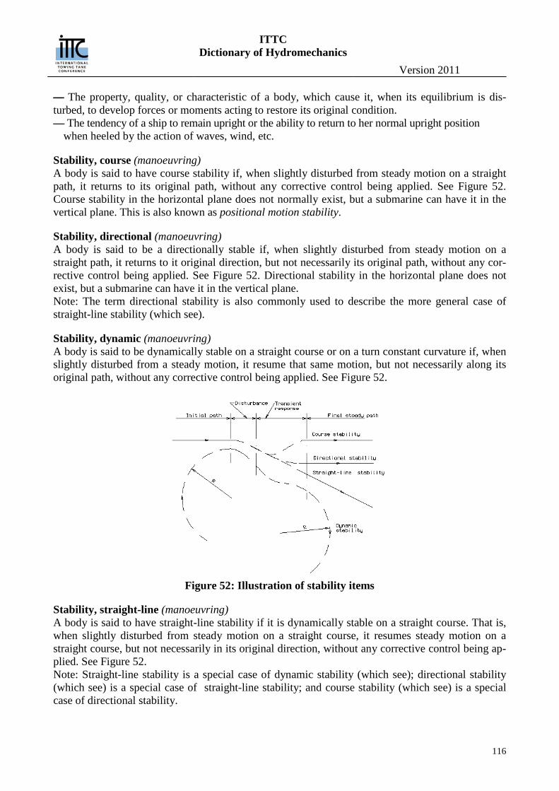
ITTC Dictionary of Hydromechanics
Version 2011
116
— The property, quality, or characteristic of a body, which cause it, when its equilibrium is dis-turbed, to develop forces or moments acting to restore its original condition. — The tendency of a ship to remain upright or the ability to return to her normal upright position
when heeled by the action of waves, wind, etc.
Stability, course (manoeuvring) A body is said to have course stability if, when slightly disturbed from steady motion on a straight path, it returns to its original path, without any corrective control being applied. See Figure 52. Course stability in the horizontal plane does not normally exist, but a submarine can have it in the vertical plane. This is also known as positional motion stability.
Stability, directional (manoeuvring) A body is said to be a directionally stable if, when slightly disturbed from steady motion on a straight path, it returns to it original direction, but not necessarily its original path, without any cor-rective control being applied. See Figure 52. Directional stability in the horizontal plane does not exist, but a submarine can have it in the vertical plane. Note: The term directional stability is also commonly used to describe the more general case of straight-line stability (which see).
Stability, dynamic (manoeuvring) A body is said to be dynamically stable on a straight course or on a turn constant curvature if, when slightly disturbed from a steady motion, it resume that same motion, but not necessarily along its original path, without any corrective control being applied. See Figure 52.
Figure 52: Illustration of stability items
Stability, straight-line (manoeuvring) A body is said to have straight-line stability if it is dynamically stable on a straight course. That is, when slightly disturbed from steady motion on a straight course, it resumes steady motion on a straight course, but not necessarily in its original direction, without any corrective control being ap-plied. See Figure 52. Note: Straight-line stability is a special case of dynamic stability (which see); directional stability (which see) is a special case of straight-line stability; and course stability (which see) is a special case of directional stability.

ITTC Dictionary of Hydromechanics
Version 2011
117
Stability, weathercock (manoeuvring) The directional or inherent stability of a body which is so restrained that its only freedom of motion is that of rotation about an axis perpendicular to the direction of relative liquid motion. The body tends to align itself with the direction of flow after being disturbed. Note: In some quarters, as in wind tunnel establishments, this is also known as “static stability”.
Stacking line (propulsion, propulsor) Synonymous with generator line. Also used to denote the blade reference line.
Standard deviation (seakeeping) The square root of the average of the squares of the deviations from the mean value; the square root of the variance.
Static (general), As an adjective, pertains to bodies or system at rest or forces in equilibrium; in this respect it is the opposite of dynamic (which see)
Static Equilibrium Stability(vessel geometry and stability) The condition where the static heeling moment equals the static righting moment
Static thrust coefficient (propulsion, propulsor) See: Thrust coefficient, static
Station (vessel geometry and stability) An imaginary transverse plane, passing through a ship, perpendicular to the baseline, to define the shape and the position of the various parts. Generally the length between perpendiculars is divided by intermediate stations into 10 or 20 equal intervals. Specifically:
Maximum area station, the station at which the transverse section has the maximum area; Midstation, the station at midlength.
Statistical Independence In probability theory, to say that two events are independent, intuitively means that the occurrence of one event makes it neither more nor less probable that the other occurs. Similarly, two random variables are independent if the conditional probability distribution of either given the observed value of the other is the same as if the other's value had not been observed. See also Loose coupl-ing and Tight coupling
Steady quasi-steady cavities (cavitation) Cavitating flow may be composed of individual transient cavities or of large cavities attached to the body on which cavitation has been induced (particularly if the detachment point is sharply defined, as for hydrofoil with sharp leading edge). The envelope of the bubbles in the former case and the cavities in the latter case are quasi-steady in the sense that envelope or cavity surface is stationary on a temporal average.
Steady state (general), This applies to a condition may be static, but is generally dynamic, in which there is no change with time. A ship moving in a straight line at uniform speed and a ship in a steady turn at uniform speed both represent steady state conditions.
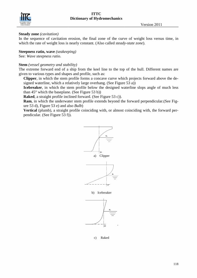
ITTC Dictionary of Hydromechanics
Version 2011
118
Steady zone (cavitation) In the sequence of cavitation erosion, the final zone of the curve of weight loss versus time, in which the rate of weight loss is nearly constant. (Also called steady-state zone).
Steepness ratio, wave (seakeeping) See: Wave steepness ratio.
Stem (vessel geometry and stability) The extreme forward end of a ship from the keel line to the top of the hull. Different names are given to various types and shapes and profile, such as:
Clipper, in which the stem profile forms a concave curve which projects forward above the de-signed waterline, which a relatively large overhang. (See Figure 53 a)) Icebreaker, in which the stem profile below the designed waterline slops angle of much less than 45° which the baseplane. (See Figure 53 b)) Raked, a straight profile inclined forward. (See Figure 53 c)). Ram, in which the underwater stem profile extends beyond the forward perpendicular.(See Fig-ure 53 d), Figure 53 e) and also Bulb) Vertical (plumb), a straight profile coinciding with, or almost coinciding with, the forward per-pendicular. (See Figure 53 f)).
a) Clipper
b) Icebreaker
´
c) Raked
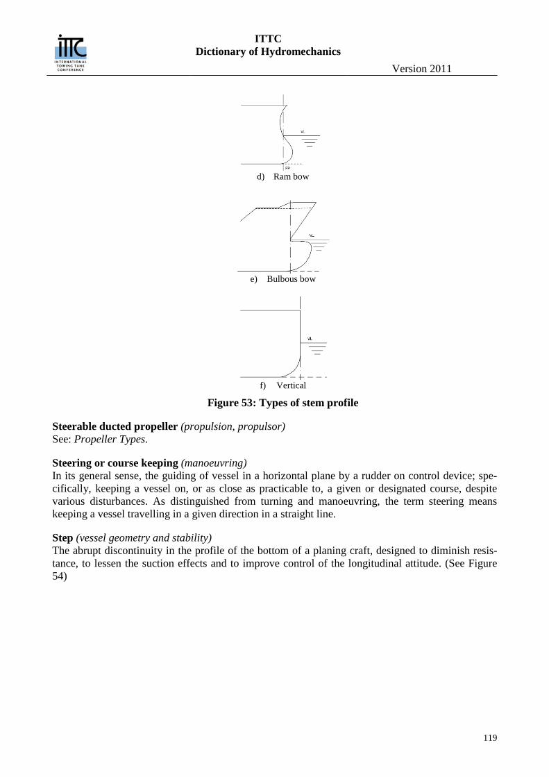
ITTC Dictionary of Hydromechanics
Version 2011
119
d) Ram bow
e) Bulbous bow
f) Vertical
Figure 53: Types of stem profile
Steerable ducted propeller (propulsion, propulsor) See: Propeller Types.
Steering or course keeping (manoeuvring) In its general sense, the guiding of vessel in a horizontal plane by a rudder on control device; spe-cifically, keeping a vessel on, or as close as practicable to, a given or designated course, despite various disturbances. As distinguished from turning and manoeuvring, the term steering means keeping a vessel travelling in a given direction in a straight line.
Step (vessel geometry and stability) The abrupt discontinuity in the profile of the bottom of a planing craft, designed to diminish resis-tance, to lessen the suction effects and to improve control of the longitudinal attitude. (See Figure 54)
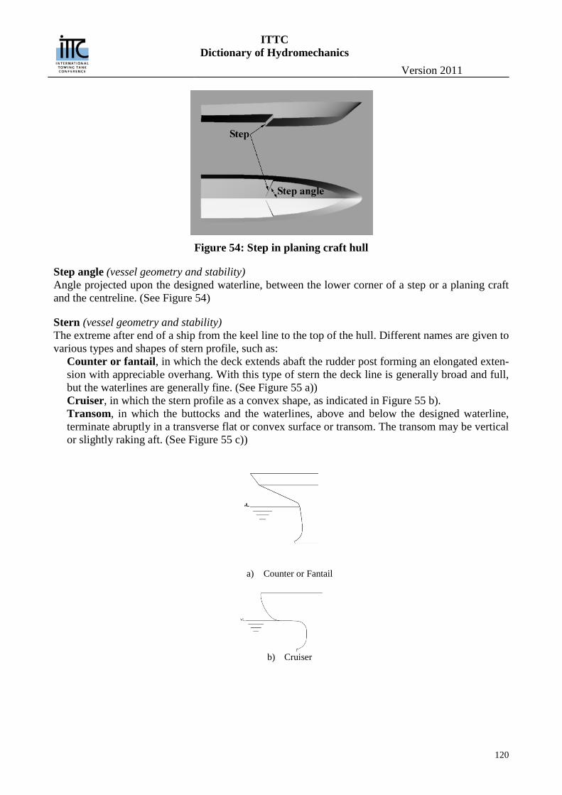
ITTC Dictionary of Hydromechanics
Version 2011
120
Figure 54: Step in planing craft hull
Step angle (vessel geometry and stability) Angle projected upon the designed waterline, between the lower corner of a step or a planing craft and the centreline. (See Figure 54)
Stern (vessel geometry and stability) The extreme after end of a ship from the keel line to the top of the hull. Different names are given to various types and shapes of stern profile, such as:
Counter or fantail, in which the deck extends abaft the rudder post forming an elongated exten-sion with appreciable overhang. With this type of stern the deck line is generally broad and full, but the waterlines are generally fine. (See Figure 55 a)) Cruiser, in which the stern profile as a convex shape, as indicated in Figure 55 b). Transom, in which the buttocks and the waterlines, above and below the designed waterline, terminate abruptly in a transverse flat or convex surface or transom. The transom may be vertical or slightly raking aft. (See Figure 55 c))
a) Counter or Fantail
b) Cruiser
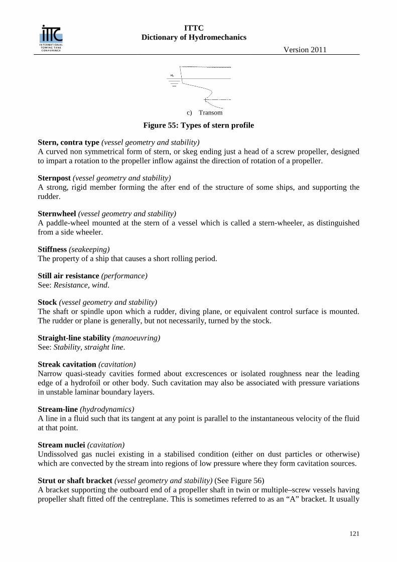
ITTC Dictionary of Hydromechanics
Version 2011
121
c) Transom
Figure 55: Types of stern profile
Stern, contra type (vessel geometry and stability) A curved non symmetrical form of stern, or skeg ending just a head of a screw propeller, designed to impart a rotation to the propeller inflow against the direction of rotation of a propeller.
Sternpost (vessel geometry and stability) A strong, rigid member forming the after end of the structure of some ships, and supporting the rudder.
Sternwheel (vessel geometry and stability) A paddle-wheel mounted at the stern of a vessel which is called a stern-wheeler, as distinguished from a side wheeler.
Stiffness (seakeeping) The property of a ship that causes a short rolling period.
Still air resistance (performance) See: Resistance, wind.
Stock (vessel geometry and stability) The shaft or spindle upon which a rudder, diving plane, or equivalent control surface is mounted. The rudder or plane is generally, but not necessarily, turned by the stock.
Straight-line stability (manoeuvring) See: Stability, straight line.
Streak cavitation (cavitation) Narrow quasi-steady cavities formed about excrescences or isolated roughness near the leading edge of a hydrofoil or other body. Such cavitation may also be associated with pressure variations in unstable laminar boundary layers.
Stream-line (hydrodynamics) A line in a fluid such that its tangent at any point is parallel to the instantaneous velocity of the fluid at that point.
Stream nuclei (cavitation) Undissolved gas nuclei existing in a stabilised condition (either on dust particles or otherwise) which are convected by the stream into regions of low pressure where they form cavitation sources.
Strut or shaft bracket (vessel geometry and stability) (See Figure 56) A bracket supporting the outboard end of a propeller shaft in twin or multiple–screw vessels having propeller shaft fitted off the centreplane. This is sometimes referred to as an “A” bracket. It usually
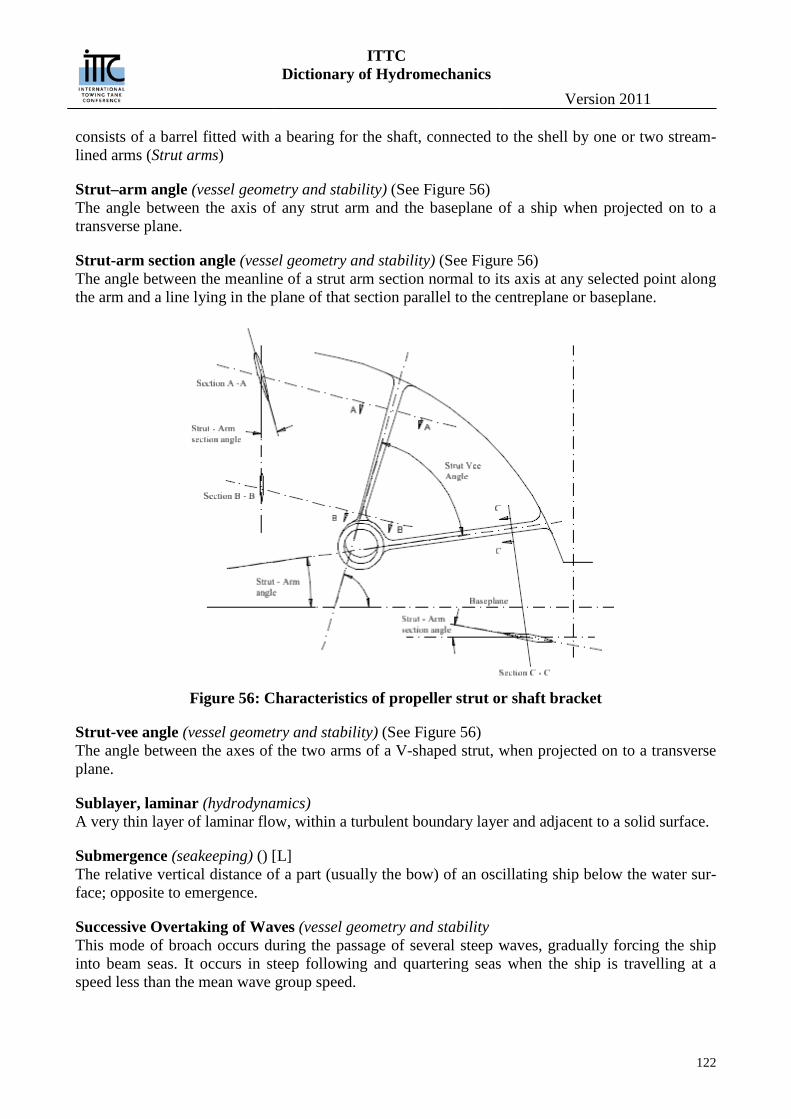
ITTC Dictionary of Hydromechanics
Version 2011
122
consists of a barrel fitted with a bearing for the shaft, connected to the shell by one or two stream-lined arms (Strut arms)
Strut–arm angle (vessel geometry and stability) (See Figure 56) The angle between the axis of any strut arm and the baseplane of a ship when projected on to a transverse plane.
Strut-arm section angle (vessel geometry and stability) (See Figure 56) The angle between the meanline of a strut arm section normal to its axis at any selected point along the arm and a line lying in the plane of that section parallel to the centreplane or baseplane.
Figure 56: Characteristics of propeller strut or shaft bracket
Strut-vee angle (vessel geometry and stability) (See Figure 56) The angle between the axes of the two arms of a V-shaped strut, when projected on to a transverse plane.
Sublayer, laminar (hydrodynamics) A very thin layer of laminar flow, within a turbulent boundary layer and adjacent to a solid surface.
Submergence (seakeeping) () [L] The relative vertical distance of a part (usually the bow) of an oscillating ship below the water sur-face; opposite to emergence.
Successive Overtaking of Waves (vessel geometry and stability This mode of broach occurs during the passage of several steep waves, gradually forcing the ship into beam seas. It occurs in steep following and quartering seas when the ship is travelling at a speed less than the mean wave group speed.
ITTC Dictionary of Hydromechanics
Version 2011
123
Suction side (propulsion, propulsor) The low pressure side of a propeller blade. Synonymous with the back of the propeller blade. Analogous to the upper surface of a wing. (see Figure 36).
Supercavitating flows (cavitation) Cavity flows in which attached, fully developed cavities extend beyond the trailing edge of the body about which the cavity is formed. (See also: Attached cavities and Fully developed cavities).
Supercavitating propeller (propulsion, propulsor) See: Propeller Types.
Supercavitation (cavitation) Term sometimes used as synonymous with Supercavitating flow (which see).
Superventilation; Superventilated flow (cavitation) Terms analogous to Supercavitating flow to denote a ventilated flow in which the cavity extends beyond the trailing edge of the body about which the cavity is formed.
Surf Riding (vessel geometry and stability) Surf riding results from the ship moving down a wave crest with increasing speed. Large dynamic side forces may result if the ship imbeds itself in the proceeding wave. These dynamic forces may add to other dynamic forces to produce a dynamic capsize. Surf riding most frequently occurs when the ship is traveling near the wave speed.
Surface, rough (performance) A surface marked by sensible or visible irregularities
Surface, smooth (performance) A surface free from irregularities sensible to the touch or visible to the naked eye. A surface is called hydraulically smooth when there is no increase of resistance due to the surface irregularities.
Surface tension (general), The property of the interface between two immiscible fluids of behaving as if it were a film under tension.
Surface, wavy (performance) A surface, which may be either smooth or rough, in which there are undulations of relatively large curvature.
Surface, wetted (vessel geometry and stability) (S) [L2] The surface area of the underwater body of a ship. This generally includes the area of the append-ages which give an appreciable contribution to the frictional drag, such as bilge keel, propeller boss-ing, and rudder. It is usually expressed in non dimensional form viz:
i.Wetted surface coefficient (CS) [-] 𝐶S = 𝑆/√𝛻𝐿
where: S = wetted surface area, L = ship length, and ∇ = volume of displacement or
ii.Froude’s wetted surface coefficient (SC) [-]
𝑆C = 𝑆/∇2 3⁄
ITTC Dictionary of Hydromechanics
Version 2011
124
Surging (seakeeping) The longitudinal oscillatory motion of a specified point in a ship, usually the centre of gravity (or origin of body axes).
Swaying (manoeuvring, seakeeping) The transverse oscillatory motion of a specified point in the ship, usually the centre of gravity.
System dynamics (general) Is an approach to understanding the behavior of complex systems over time. It deals with internal feedback loops and time delays that affect the behavior of the entire system. What makes using sys-tem dynamics different from other approaches to studying complex systems is the use of feedback loops and stocks and flows. These elements help describe how even seemingly simple systems dis-play baffling nonlinearity
ITTC Dictionary of Hydromechanics
Version 2011
125
T Tab (manoeuvring) A small auxiliary foil, movable or fixed, attached to a control surface such as a rudder or diving plane, generally at its after edge, to reduce the control force or moment by applying local differen-tial pressure to the main control surface.
Tangential induced velocity (propulsion, propulsor) See: Induced velocity, tangential.
Taylor’s advance coefficient (propulsion, propulsor) See: Advance coefficient, Taylor’s
Taylor’s power coefficient (propulsion, propulsor) (BU, BP) See: Power coefficient, Taylor’s.
Thickness, local (propulsion, propulsor) (tX) [L] The thickness of a propeller blade section at any location along the X axis of the section reference system, generally measured in the direction normal to the chord line. (See Figure 18).
Thickness, maximum (propulsion, propulsor) (t) [L] The maximum thickness of a propeller blade section, generally measured in the direction normal to the chord line. (See Figure 18).
Thickness ratio (propulsion, propulsor) (δ) [-] The ratio of the maximum thickness, t, of a foil section to the chord length, c, of that section.
Thoma number (cavitation) (Th)[-] The ratio of the difference between total head and the vapour pressure (upstream of the impeller of rotating machinery) to the total head produced or absorbed by the machine.
Thrust (propulsion, propulsor) (T) [MLT-2] The force developed by a screw propeller in the direction of the shaft.
Thrust breakdown (propulsion, propulsor) The phenomenon of loss of thrust due to excessive cavitation on a subcavitating type propeller. The torque absorbed by the propeller is affected similarly and is called torque breakdown. Both the thrust and torque coefficient may increase slightly above noncavitating values near the initial incep-tion of cavitation. In general, the changes in thrust and torque are such that propeller efficiency is reduced.
Thrust coefficient (propulsion, propulsor) (KT) [-] The thrust, T, produced by propeller expressed in coefficient form:
ITTC Dictionary of Hydromechanics
Version 2011
126
𝐾𝑇 = 𝑇/(𝜌𝑛2𝐷4)
where ρ is the mass density of the fluid, n is the rate of propeller rotation, and D is the propeller di-ameter.
Thrust coefficient, static (propulsion, propulsor) () [-] A figure of merit for comparing the relative performance of propulsion devices at zero speed given by the equation:
𝑇
(𝜌𝜋/2)13(𝑃𝐷𝐷)
23
=𝐾𝑇
𝜋�𝐾𝑄�232
13
The ideal upper limit for unducted screw propellers is 1.0, while for ducted propellers the upper limit depends upon the area ratio of the downstream diffuser. When the area ratio is unity, i.e. no diffusion or contraction, the limit is 21/3 = 1.26; ρ is the fluid density, D propeller diameter, PD de-livered power; KT and KQ are the thrust and torque coefficients respectively (which see).
Thrust deduction factor (performance) (t) [-] It is logical to view the effect of the propeller behind the hull as causing an increase in resistance- See: Resistance augment fraction. However, it is also common practice to look upon this increase in RT as a deduction from the thrust T available at the propeller, i.e. to assume that of the total thrust T only RT is available to overcome resistance. This “loss of thrust” TT R , expressed as a fraction of the thrust T, is called the thrust deduction fraction, t, where
TT Rt
T
or
1TR t T
Thruster (propulsion, propulsor) A propulsion device for zero or low speed manoeuvring of vessels.
Thrust index (propulsion, propulsor) (CT*) [-] The thrust, T, produced by the propeller expressed in coefficient form:
𝐶𝑇∗ =𝑇
12𝜌[𝑉A2 + (0.7𝑛𝐷)2](𝜋𝐷2/4)
where ρ is the density of fluid, VA is the speed of advance, n is the rate of rotation and D is the pro-peller diameter. This form of the thrust coefficient is useful when presenting propeller thrust charac-teristics over a range of advance coefficients from zero (VA = 0) to infinity (n = 0). Usually pre-sented as a function of
𝛽∗ = tan−1[𝑉A/(0.7𝜋𝑛𝐷)]
Thrust in waves, mean increase in (seakeeping) (TAW) [MLT-2] The mean increase in thrust, as compared with that in smooth water, necessary to maintain speed in wind and waves.
Thrust loading coefficient (propulsion, propulsor) (CTh) [-]
ITTC Dictionary of Hydromechanics
Version 2011
127
The thrust, T, produced by the propeller expressed in coefficient form:
𝐶𝑇ℎ =𝑇
𝜌2𝑉𝐴
2 𝜋𝐷24=𝐾𝑇𝐽2
8𝜋
where ρ is the mass density of the fluid, VA is the speed of advance, D is the propeller diameter, ( the symbol CTS is used when this coefficient is based on ship speed instead of speed of advance).
Where KT and J are the thrust and advance coefficient respectively (which see).
Thrust power (performance) See: Power, thrust.
Tight Coupling (general) (Bookstaber, 2007) —Tight coupling means that components of a process are critically interdependent and thus non-Gaussian. They are linked with little room for error or time for recalibration or adjust-ment. A process that is tightly coupled can be prone to accidents even if it is not complex. It can also be applied to a time-driven system in which one event leads to another in short order, i.e. a chain accident with no time to correct the actions. Other system failures grow out of a chain or er-rors and mishaps over time without the operators discovering the source of the misinformation as was the case for the Three Mile Island accident
Tilt (vessel geometry and stability) An inclination of ship or its parts from the vertical or upright position, generally in a transverse or athwartship plane.
Time Series Analysis (general) (Mainzer2007 p78, p338) —A bottom-up approach that aims to construct a black box, which takes the measured data as input and provides as output a mathematical model describing the data. However, it is rather difficult to reconstruct an underlying attractor and its dimension d. For chaotic systems with d>3, it is a challenge to distinguish between a chaotic time evolution and a random process, especially if the underlying deterministic dynamics are unknown.
Tip cavitation (cavitation) Surface cavitation which occurs near the tip propeller blade.
Tip vortex cavitation (cavitation) Cavitation occurring in the low-pressure core of the tip vortex of a hydrofoil or propeller.
Toe angle of an offset rudder (manoeuvring) See: Angle, toe, of an offset rudder.
Torque (propulsion, propulsor) (Q) [ML2T-2] The torque delivered to the propeller aft of all bearings.
Torque breakdown (propulsion, propulsor) See: Thrust breakdown.
Torque coefficient (propulsion, propulsor) (KQ) [-] The torque, Q, delivered to the propeller expressed in coefficient form:
ITTC Dictionary of Hydromechanics
Version 2011
128
𝐾𝑄 =𝑄
𝜌𝑛2𝐷5
where ρ is the density of the fluid, n is the rate of propeller rotation, and D is the propeller diameter.
Torque index (propulsion, propulsor) (CQ*) [-] The torque, Q, absorbed by the propeller expressed in coefficient form:
𝐶𝑄∗ =𝑄
12𝜌[𝑉A2 + (0.7𝑛𝐷)2](𝜋𝐷3/4)
where ρ is the density of fluid, VA is the speed of advance, n is the rate of rotation and D is the di-ameter. This form of the torque coefficient is useful when presenting propeller torque characteristics over a range of advance coefficients from zero (VA = 0) to infinity (n = 0). Usually presented as a function of
𝛽∗ = tan−1[𝑉A/(0.7𝜋𝑛𝐷)].
Torque in waves, mean increase in (seakeeping) (QAW) [ML2T-2] The mean increase in torque as compared with that in smooth water, necessary to maintain speed in wind and waves.
Torque or moment, hinge or stock, of a control surface (manoeuvring) (QR, QFB, QFS, etc.) [L2MT-2] The torque applied to the stock or actuating mechanism of a control surface by the hydrodynamic forces acting upon it. Also the torque applied to the control surface through the stock or actuating mechanism to change the position or attitude of that surface, e.g. rudder torque QR, bow fin torque QFB, stern fin torque QFS, etc.
Total gas content (cavitation) See: Gas content.
Total rake (propulsion, propulsor) See: Rake, total.
Total Stability Failure, or Capsizing (vessel geometry and stability) (IMO), results in total loss of a ship’s operability with likely loss of lives. Capsizing could be for-mally defined as a transition from a nearly stable upright equilibrium that is considered safe, or from periodic motions near such equilibrium, passing through a far from equilibrium state that is in-trinsically unsafe (or could be considered unacceptable from a practical point of view)
Towing force, for model at ship-point of self-propulsion (performance) See: Force, model towing.
Tow point (manoeuvring) The point at which the towing force is applied on a ship which is towing or on a craft which is being towed.
Track (performance) The path along which the centre of gravity of a ship is moving (See Fig. 24). (manoeuvring) The path at which the centre of gravity of a ship is moving. See Figure 23.
ITTC Dictionary of Hydromechanics
Version 2011
129
Trail, trailing (manoeuvring) As applied to a movable appendage or control surface, that condition in which the surface aligns it-self with the surrounding flow, leading end foremost when all control force or moment is removed. An unbalanced rudder pivoted at its forward edge always trails when going ahead.
Trailing edge (propulsion, propulsor) Blade edge opposite to the inflow under normal operating conditions starting from the blade root and ending at the blade tip. ( See Figure 32).
Trailing vortex cavitation (cavitation) Persisting cavitation in the low-pressure core of trailing vortices downstream of hydrofoils or pro-pellers. (See also: Tip vortex cavitation and Hub vortex cavitation).
Transfer (manoeuvring) The lateral offset of the CG of a body or ship in the first quadrant of turn, measured laterally from the extended approach path to the CG position when the body or ship has changed course 90 de-grees. See Figure 1.
Transfer maximum (in stopping) The lateral offset of the centre of gravity of a body or ship before coming to rest after having exe-cuted a crash-back manoeuvre from a steady, straight-line motion ahead. See Figure 2
T Transfer function (seakeeping) See: Response function.
ransient (seakeeping) Irregular or non-harmonic, such as the free vibration of a damped mechanical system.
Transient cavities (cavitation) Cavitation bubbles that grow from nuclei, sometimes oscillate (if containing a high volume of per-manent gas component) and eventually collapse and disappear.
Transom (vessel geometry and stability) See: Stern
Trapped gas (cavitation) Undissolved gas trapped in the cavities of foreign particles or the crevices of the boundary under study.
Trial, measured mile (performance) A trial carried out on a measured mile course to determinate the performance characteristics of a ship, namely ship speed, corresponding rate of rotation of propeller shaft, power, and also thrust where practicable.
Trim (vessel geometry and stability) (-) [L] The difference between the draught forward TF and the draught aft TA for a ship with a designed level keel:
Trim = TF - TA In non dimensional form the trim is expressed as a fraction of the ship length, i.e. (TF - TA)/L and is called the trim ratio. It is referred to as trim by the bow or head if the forward draught is the greater,
ITTC Dictionary of Hydromechanics
Version 2011
130
level trim if both are the same and trim by the stern if the draught aft is the greater. If the ship has a designed initial trim (raked keel or drag) the trim is generally measured with respect to this initial longitudinal inclination.
Trim (seakeeping, manoeuvring) The steady-state longitudinal angular position of a ship; to be distinguished from pitching, which is an oscillatory motion.
Trim, angle of (seakeeping, manoeuvring ) (θ) [-] The angle, measured about a horizontal axis, between the position of the longitudinal axis of a ship at rest and the horizontal plane.
True wind direction or velocity See: wind direction or velocity, true.
Tumblehome (vessel geometry and stability) The slant inward from the vertical of a transverse section of a hull above the designed waterline. It is the opposite of flare.
Turning (manoeuvring) That phase of manoeuvring in which a body or ship while moving ahead or astern, changes course or direction. The beginning of a turn, starting with the initial deviation from the approach path, is known as the “entry” into the turn; the end of a turn terminating in a new straight course, is known as the “sortie”. See Figure 1.
Turning, steady (manoeuvring) That phase of the turning in which the rate of change of heading steadies to a constant value.
Turtleback or turtleback deck (vessel geometry and stability) A form of weather deck with large camber which is rounded over at the sides in order to shed the water rapidly in heavy weather; also called turtle deck.
ITTC Dictionary of Hydromechanics
Version 2011
131
U Uncertainty (general) The lack of certainty, A state of having limited knowledge where it is impossible to exactly describe existing state or future outcome, more than one possible outcome.
Uncertainty Analysis (general) (ITTC) —Uncertainty results may be grouped in 2 categories called Type A uncertainty and Type B uncertainty. They are defined as follows: Type A uncertainties are those evaluated by applying statistical methods to the results of a series of repeated measurements. The components in type A uncertainty are defined by the estimated va-riance, which includes the effect of the number of degrees of freedom (DOF). Type B uncertainties are those evaluated by other means. The definition has been further refined by ISO (1995) to include prior experience and professional judgments, manufacturer’s specifications, previous measurement data, calibrations, and reference data from handbooks. The components in type B uncertainty are also approximated by a corresponding variance, in which its existence is as-sumed. The combined uncertainty should be computed by the normal method for the combination of va-riances, now known as the law of propagation of uncertainty. For particular applications, the com-bined uncertainty should be multiplied by a coverage factor to obtain an overall uncertainty value. The overall uncertainty is now called expanded uncertainty. For the 95 % confidence level, the commonly applied coverage factor is 2.
Uncertainty, Measurement of (general) A set of possible states or outcomes where probabilities are assigned to each possible state or out-come - this also includes the application of a probability density function to continuous variables
Unsteady or transient (general), These apply to a condition which is invariably dynamic, in which the motion of body or the flow of a liquid changes with time, with reference to an assumed set of axes.
Unsteady cavities (cavitation) Attached cavities which alternately grow (resembling steady cavities at any instant) – extending downstream from the point of attachment and collapse (i.e. sudden reduction in length), presumably by cyclic filling by the re-entrant flow and subsequent re-evaporation.
ITTC Dictionary of Hydromechanics
Version 2011
132
V Valid (general) Being supported by objective truth or generally accepted authority, based on flawless reasoning and solid ground, well grounded, sound, having a conclusion correctly derived from premises, cogent, convincing.
Vapour cavitation number (cavitation) See: Cavitation number, vapour.
Vapour pressure (general), The pressure of vapour in equilibrium with its liquid state. It is also called the saturated vapour pressure or vapour tension, which for a given substance depends only upon the temperature.
Vaporous cavitation (cavitation) A nucleus (which see) that grows explosively (after reaching critical size) contains mostly vapour phase, the diffusion time being too short for any significant increase in gas volume. This process, which depends upon evaporation of the liquid into the growing bubble, is a true cavitation and is called vaporous cavitation, For such cavitation to occur, pressure below vapour pressure are re-quired.
Variable pitch (propulsion, propulsor) See: Pitch, variable.
Velocity, induced (propulsion, propulsor) See: Induced velocity (axial, tangential, and radial).
Velocity potential (hydrodynamics) See Potential function.
Ventilated flow (cavitation) A ventilated flow is one in which a “cavity” is formed entirely with air (or other permanent gas).
Ventilation (cavitation) Process by which a ventilated flow is formed and maintained. Natural ventilation is applied to a ventilated flow which derives a continuous flow of gas by means of the pressure created by the flow itself, as from the free surface in the case of a surface piercing, ventilated strut. Forced ventilation is applied to a ventilated flow in which the permanent gas is continuously supplied into the cavity by auxiliary means such as a pump.
Ventilation inception (cavitation) Ventilation inception is defined as the condition at which air (or permanent gas) is drawn into the low-pressure region in a non-cavitating flow, from an external source, as at the free surface of a liq-uid.
ITTC Dictionary of Hydromechanics
Version 2011
133
Ventilation index (cavitation) The ratio of the volumetric air feed rate to the product of free stream velocity and an area propor-tional to the cavity cross sectional dimension or to some typical body dimension.
Ventilated propeller (propulsion, propulsor) See: Propeller Types.
Vertical-axis propeller (propulsion, propulsor) Synonymous with cycloidal propeller. See: Propeller Types.
Virtual mass (seakeeping) The combined effect of the mass of he ship and added mass corresponding to the hydrodynamic forces in phase with and proportional to the acceleration. (See also: Added mass.)
Viscosity coefficient of dynamic (general) (µ) [L-1 M T-1]*, The ratio of the shearing stress in a fluid to its rate of shear deformation. See also: Resistance sec-tion. * For standard values of fresh water and salt water at 15° C ( 59° F ) see: Performance Section un-der “Water standard fresh and salt”. For values over a range of temperature in S.I units see in “Met-rication Ship Research and Design”, Paffett, J.A.H. Trans. RINA, 1971; for corresponding values in Imperial Unit see Proceedings 10th International Towing Tank Conference, London 1963 or Na-tional Physical Laboratory, Ship Division Report No. 81 (1966).
Viscosity, coefficient of dynamic (hydrodynamics) (µ) [L-1MT-1] The quantity expressing the resistance of a fluid to internal shear; the ratio of tangential stress to rate of shear deformation in flow of an incompressible Newtonian fluid. For unidirectional shear flow:
𝜇 =𝜏
d𝑈 d𝑦⁄
Viscosity, coefficient of kinematic (hydrodynamics) (ν) [L-1MT-1] The ratio of the coefficient of dynamic viscosity to the mass density of the fluid:
𝜈 =𝜇𝜌
See also General Section under “Liquid Properties and Physical Constants”
Volume loss (cavitation) (VL) [L3] An alternative criterion to weight loss for assessing cavitation damage, often derived from weight loss by using the density of the specimen material.
Volume of Fluid (VOF) Methods (general) The VOF model can model two or more immiscible fluids by solving a single set of momentum eq-uations and tracking the volume fraction of each of the fluids throughout the domain. Typical appli-cations include the prediction of jet breakup, the motion of large bubbles in a liquid, the motion of liquid after a dam break, and the steady or transient tracking of any liquid-gas interface including the dynamic free surface effect
Vortex cavitation (cavitation)

ITTC Dictionary of Hydromechanics
Version 2011
134
See: Hub vortex cavitation, Tip vortex cavitation and Trailing vortex cavitation.
ITTC Dictionary of Hydromechanics
Version 2011
135
W Wake (performance) The wake is a term used to describe the motion imparted to the water by the passage of the ship’s hull. It is considered to be positive if its direction is the same as that of the ship.
Wake fraction (performance) (w, wF) [-] The difference between the ship speed V and the speed of advance VA is called the wake speed AV V . Froude expressed the wake speed at the position of the propeller as a fraction of the speed of advance, calling this ratio the wake fraction wF, such that
AF
A
V Vw
V
and AF1
VV
w
Taylor expressed the wake speed at the position of the propeller as a fraction of the ship speed, such that
AV Vw
V
and A 1V V w .
Wake fraction, nominal (performance) [-] Wake fractions calculated from speed measured at the propeller position by Pitot tube, vane wheels, etc. in the absence of the propeller are called nominal wakes.
Wake fraction, torque (performance) (wQ) [-] A propeller will develop the same torque Q at the same revolutions per unit time, n, when working behind a hull advancing at speed V and in open water at a speed of advance VA. The torque wake fraction will then be
AQ
V Vw
V
This depends on identity of torque.
Wake fraction, thrust (performance) (wT) [-] A propeller will develop the same thrust T at the same revolutions per unit time, n, when working behind a hull advancing at speed V and in open water at a speed of advance VA. The thrust wake fraction will then be
AT
V Vw
V
This depends on identity of thrust.
Wake, frictional (performance) The component of the wake which results from the frictional action of the water when moving along the solid surface of a body or ship.
ITTC Dictionary of Hydromechanics
Version 2011
136
Wake, potential (performance) The component of the wake due to the potential flow around a body or ship, with velocity and pres-sure relationship in accordance with Bernoulli’s Theorem.
Wake, wave or orbital (performance) The component of the wake set up by the orbital motion in the waves created by a body or ship.
Wall nuclei (cavitation) The undissolved gas nuclei which may exist in equilibrium in the crevices of the boundary wall ma-terial.
Warp (propulsion, propulsor) () [-] Synonymous with skew angle.
Wash-back (propulsion, propulsor) See: Set-back.
Wash-down (propulsion, propulsor) See: Set-back.
Wash-up (propulsion, propulsor) See: Set-back.
Water jet (propulsion, propulsor) A form of propulsion in which water is taken into hull of the ship by means of ducting and energy is imparted to the water with a pump. The water is then ejected astern through a nozzle.
Waterline (vessel geometry and stability) This term is used to indicate:
i.The intersection line of the free water surface with the moulded surface of a ship, either in still water or when it is surrounded by waves of its own making.
ii.The intersection line of any selected plane, parallel to the baseplane, with the moulded surface of a ship. (See Figure 57)
The angle of the waterline at the bow in the horizontal plane neglecting local shape at stern is the Angle of entrance. This is generally designated as the Half angle of entrance (iE) [-] i.e. with respect to the centreplane - See Figure 57. The angle of the waterline at the stern in the horizontal plane neglecting local shape of stern frame is the Angle of the run. This is generally designated as Half angle of run (iR) [-] i.e. with respect to the centreplane – See Figure 57.
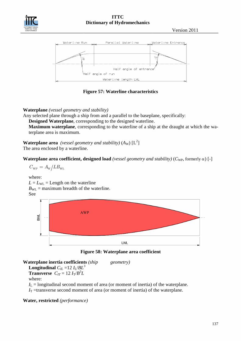
ITTC Dictionary of Hydromechanics
Version 2011
137
Figure 57: Waterline characteristics
Waterplane (vessel geometry and stability) Any selected plane through a ship from and a parallel to the baseplane, specifically:
Designed Waterplane, corresponding to the designed waterline. Maximum waterplane, corresponding to the waterline of a ship at the draught at which the wa-terplane area is maximum.
Waterplane area (vessel geometry and stability) (AW) [L2] The area enclosed by a waterline.
Waterplane area coefficient, designed load (vessel geometry and stability) (CWP, formerly α) [-]
WP W WLC A LB
where: L = LWL = Length on the waterline BWL = maximum breadth of the waterline. See
Figure 58: Waterplane area coefficient
Waterplane inertia coefficients (ship geometry) Longitudinal CIL =12 IL/BL3 Transverse CIT = 12 IT/B3L where: IL = longitudinal second moment of area (or moment of inertia) of the waterplane. IT =transverse second moment of area (or moment of inertia) of the waterplane.
Water, restricted (performance)
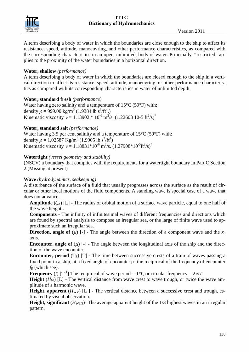
ITTC Dictionary of Hydromechanics
Version 2011
138
A term describing a body of water in which the boundaries are close enough to the ship to affect its resistance, speed, attitude, manoeuvring, and other performance characteristics, as compared with the corresponding characteristics in an open, unlimited, body of water. Principally, “restricted” ap-plies to the proximity of the water boundaries in a horizontal direction.
Water, shallow (performance) A term describing a body of water in which the boundaries are closed enough to the ship in a verti-cal direction to affect its resistance, speed, attitude, manoeuvring, or other performance characteris-tics as compared with its corresponding characteristics in water of unlimited depth.
Water, standard fresh (performance) Water having zero salinity and a temperature of 15°C (59°F) with: density ρ = 999.00 kg/m3 (1.9384 lb s2/ft4.) Kinematic viscosity ν = 1.13902 * 10-6 m2/s. (1.22603 10-5 ft2/s)*
Water, standard salt (performance) Water having 3.5 per cent salinity and a temperature of 15°C (59°F) with: density ρ = 1,02587 Kg/m3 (1.9905 lb s2/ft4) Kinematic viscosity ν = 1.18831*10-6 m2/s. (1.27908*10-5ft2/s)*
Watertight (vessel geometry and stability) (NSCV) a boundary that complies with the requirements for a watertight boundary in Part C Section 2.(Missing at present)
Wave (hydrodynamics, seakeeping) A disturbance of the surface of a fluid that usually progresses across the surface as the result of cir-cular or other local motions of the fluid components. A standing wave is special case of a wave that does not advance.
Amplitude (ζA) [L] - The radius of orbital motion of a surface wave particle, equal to one half of the wave height . Components - The infinity of infinitesimal waves of different frequencies and directions which are found by spectral analysis to compose an irregular sea, or the large of finite wave used to ap-proximate such an irregular sea. Direction, angle of (µ) [-] - The angle between the direction of a component wave and the x0 axis. Encounter, angle of (µ) [-] - The angle between the longitudinal axis of the ship and the direc-tion of the wave encounter. Encounter, period (TE) [T] - The time between successive crests of a train of waves passing a fixed point in a ship, at a fixed angle of encounter µ; the reciprocal of the frequency of encounter fE (which see). Frequency (f) [T-1] The reciprocal of wave period = 1/T, or circular frequency = 2π/T. Height (HW) [L] - The vertical distance from wave crest to wave trough, or twice the wave am-plitude of a harmonic wave. Height, apparent (HWV) [L ] - The vertical distance between a successive crest and trough, es-timated by visual observation. Height, significant (HW1/3)- The average apparent height of the 1/3 highest waves in an irregular pattern.
ITTC Dictionary of Hydromechanics
Version 2011
139
Instantaneous elevation (η) [L] - The instantaneous elevation of a point in a wave system above the level of the undisturbed surface. Length (LW, λ) [L] The horizontal distance between adjacent wave crests in the direction of ad-vance. Length, apparent ( WVL ) [L] - The horizontal distance between adjacent wave crests of an ir-regular sea in the direction of advance. Number (κ) [L-1]
𝜅 =2𝜋𝜆
or 2𝜋𝐿W
Period (TW) [T] - The time between the passage of two successive wave crests passed a fixed point. Period, apparent (TWV) [T] - The time elapsing between the occurrence of two successive crests of an irregular sea, or between two successive upward crossing of zero in a record, estimated by visual observation. Profile - The elevation of the surface particles of a wave plotted as a function of space in a fixed time. Slope of surface - The surface slope of a wave profile perpendicular to the crest in space co-ordinate. Maximum wave slope of a regular harmonic or trochoidal wave is π/2 x steepness ratio. Speed celerity (cW) [LT-1] - The phase velocity of a surface gravity wave in deep water.
𝑐W = �𝑔𝐿W2𝜋
Steepness ratio - The ratio of wave height to length. Train - A continuous sequence of wave crests and hollows. Trochoidal - A profile closely approximating that of a regular surface gravity wave in a fluid; it can be geometrically constructed by tracing the path of a point on the radius of a circle as the cir-cle rolls along the underside of a horizontal line.
Wave, angle of diverging (hydrodynamics) The acute angle, measured in the horizontal plane, between axis of motion of a body and the normal to the crest or trough line.
Wave encounter period (seakeeping) (TE) [T] The time between successive crests of a train of waves passing a fixed point in a ship, at a fixed an-gle of encounter µ; the reciprocal of the frequency of encounter fE (which see).
Wavelet Analysis (general) Unlike Fourier methods that determine only the frequency content of a signal, the wavelet analysis determines both the frequency and the time. This is owing to the nature of the basis functions, which are infinite for Fourier transforms (sines and cosines are infinite), but are finite for wavelet analysis (wavelets are localized waves). Wavelet analysis, and especially its generalized version — wavelet packet analysis — can successfully track spectral changes of Monte Carlo simulations
Wavy surface (performance) See: Surface, wavy.
Weibull Distribution (general)
ITTC Dictionary of Hydromechanics
Version 2011
140
A two parameter it can mimic the behavior of other statistical distributions such as the normal and the exponential. If the failure rate decreases over time, then k < 1. If the failure rate is constant over time, then k = 1. If the failure rate increases over time, then k > 1.
Weight loss (cavitation) (WL) [LMT-2] Weight of material actually eroded from a specimen during a specified time while undergoing ero-sion damage. The most widely used measure of cavitation damage.
Weather Deck (vessel geometry and stability) (NSCV) A deck which is completely exposed to the weather from above and from at least two ver-tical boundaries to the space.
Weathercock stability (manoeuvring) See: Stability, weathercock.
Weathertight (vessel geometry and stability) — (old NSCV) a boundary such that, in any wind and wave conditions, water will not penetrate into the vessel. — (new NSCV) a boundary that complies with the requirements for a weathertight boundary in Part C Section 2.(missing at present) NOTE: A watertight boundary also meets the requirements of a weathertight boundary.
Well Deck Vessel (vessel geometry and stability) (NSCV) a vessel having an exposed recess, which extends for more than 50 per cent of the water-line length of the vessel.
Wetness (seakeeping) The quality of a part of the ship, usually the weatherdeck forward, with respect to its liability of be-ing wet as a result of motions of ship and waves.
Whipping (seakeeping) The transient ship-hull vibration which is induced by impulsive excitation forces. For example, fore-bottom slamming, bow-flare slamming, shipping of water and stern slamming. (See also: Springing).
Wind, angle measured apparent (vessel geometry and stability performance) (βAW) [-] The direction of the relative wind with respect to a ship’s heading. The resultant direction of the wind induced by the ship’s motion and the true wind, if any.
Wind, Angle, Corrected Apparent() The direction of the relative wind corrected by roll, pitch and yaw at the anemometer.
Wind, angle true (vessel geometry and stability, performance) (βTW) [-] The direction of the wind , if any, with respect to a ship’s heading.
Wind direction (vessel geometry and stability,performance) (θW) [-] The direction of any natural or atmospheric wind blowing over the ground or over the surface of the sea, measured from the true North.
Windmilling (propulsion, propulsor)
ITTC Dictionary of Hydromechanics
Version 2011
141
The rotation of a propeller caused by flow past the propeller without power being applied to the propeller shaft. This action may take place while the ship is moving under its own momentum, while it is being towed, or while it is being propelled by other means of propulsion.
Wind resistance (performance) See: Resistance wind.
Wind velocity, corrected relative (vessel geometry and stability, performance) The velocity of the relative wind corrected for roll, pitch and yaw at the anemometer..
Wind velocity, measured relative (vessel geometry and stability, performance) (VWR ) [LT-1] The velocity of the wind relative to the ship. It is the resultant of the wind induced by the ship’s mo-tion and the true wind, if any.
Wind velocity, true (vessel geometry and stability, performance) (VWT ) [LT-1] The velocity of a natural wind relative to the ground.
Windward side (vessel geometry and stability) The side of a ship on which the wind blows. It is the opposite to the leeward side.

ITTC Dictionary of Hydromechanics
Version 2011
142
X
ITTC Dictionary of Hydromechanics
Version 2011
143
Y Yaw, angle (χ) [-] (performance, manoeuvring, seakeeping) The angle, measured about the vertical body axis, between the instantaneous position of the longitudinal centreplane of a ship when yawing (which see) and its mean heading. (Positive bow to starboard).
Yawing (manoeuvring, seakeeping) The angular component of the oscillatory motion of a hull about a vertical axis.
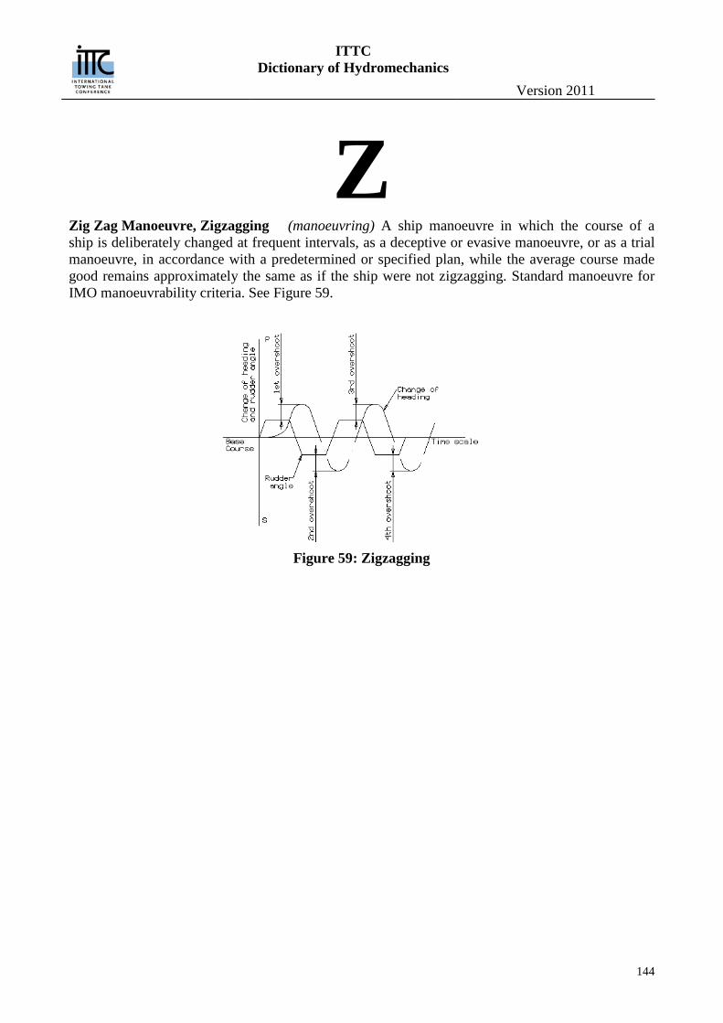
ITTC Dictionary of Hydromechanics
Version 2011
144
Z Zig Zag Manoeuvre, Zigzagging (manoeuvring) A ship manoeuvre in which the course of a ship is deliberately changed at frequent intervals, as a deceptive or evasive manoeuvre, or as a trial manoeuvre, in accordance with a predetermined or specified plan, while the average course made good remains approximately the same as if the ship were not zigzagging. Standard manoeuvre for IMO manoeuvrability criteria. See Figure 59.
Figure 59: Zigzagging