Embed Size (px)
Citation preview

THERMO-MECHANICAL TESTS ON TRACKER LADDERS(Low temperature problem on plane 1)
Status Report: D.Rapin Sept 26,2012 (help from Giovanni, Franck, Mingming,...)
GOALS: • Verification of ladder integrity in case of many low temperature excursions. • If possible a better understanding of behavior of ladder mechanics and geometry with temperature.
FACTS:• Ladders were built at ~ +20°C• For ladders close to the center of plane 1, an almost constant temperature gradient of ~23°C is present between hottest part of the ladder (hybrid) and the coldest part (last wafer)• Four cold periods per year (Four cold excursions per year).• Temperature of coldest wafers in plane 1 ranges between -3°C and -15°C.• Temperature of front-end hybrids is above 5°C.
in normal operation !

Ladder components
Flexibility

Thermo-elastic calculations showed that the critical problem may be the shear stresses applied to the glue (Araldit 2011,no post curing) which bonds the Upilex (Kapton) cable and the Silicon wafers together. It is due to the different thermal expansion of the two materials.
Two experimental studies:• Study of mechanical integrity (Look for possible mechanical damages)
• (Geometry vs temperature not yet started)
Reinforcement and fixation on support plane

STUDY OF MECHANICAL INTEGRITYof the wafer assembly part of ladders
Significant damages on ladder are detected through:• Displacement of components.• Weakness of assembly (displacement of components after application of a reasonable force.)• Weakness of micro-bonds (not expected)
60 thermal cycles simulating 15 years of thermal stresses:• First 0 to -20 deg (slightly worse than present situation)• Then +5 to -30 deg ...if previous test ...• And +10 to -40 deg ... is successful.
Tests and measurements on ladders:• 3D Metrology (optics) and visual tests (integrity of the legs gluing)• Peeling test: Pull-out with a 2 Newton force (100 time the weight of one wafer) on each corner of each wafer.• Read-out of strain gauges during cycling. A crack in the structure will produce a sudden change of the constraints. Will also provide a verification of model.• Micro-bonds quality (force needed to break it)

STUDY OF MECHANICAL INTEGRITY
Material for the tests:• A mock-up of a portion of plane1 with fixations for 11- or 12-wafers ladders was built by RWTH Aachen. • Ladders available for tests with 11 or 12 wafers:• UniGe: Mech.Proto, Flight:L11GI007, ExhibitionLadder, Two AMS01 ladders• Perugia: 1 AMS02 with legs, 5 AMS02 without legs (feet).• Only few ladders available Extract the maximum of information from the tests.• Read-out equipment for strain gauges (provided by Perugia).• A climate chamber (dry air) is available at UniGe (used by ATLAS).• Lab, workshop and 3D optical metrology (MicroVu) available at UniGe. Logistics Tests made at DPNC-UniGe (... then at Terni if vacuum mandatory)
Sequence of tests:• Metrology / 60 thermal cycles/ Metrology and comparison• Pull-out test / Metrology and comparison• If no apparent damages, repeat with more severe temperature limits.• Performed on 2 ladders: Mech.Proto, Flight:L11GI007

Honeycomb support plane with inserts (Aachen)
11-wafer mechanical prototype mounted
(L0)

L11GI007 flight ladder (L1) on honeycomb in climate chamber

UniGe climate chamber
~1 m3
-55 to 180 deg
(used by ATLAS)
Perugia strain gauges read-out equipment.
Software prepared by Giovanni Ambrosi.

L1t2 (L11GI007) +5 to -30 deg cycles
-40
-30
-20
-10
0
10
20
30
40
50
600 21600 43200 64800 86400 108000 129600 151200 172800 194400 216000
Temperatur (°C) HR_mesuré (%HR)Beginning (8 hours)
-40
-30
-20
-10
0
10
20
30
40
50
60
0 3600 7200 10800 14400 18000 21600 25200 28800
Temperatur (°C) HR_mesuré (%HR)
End (8 hours)
-40
-30
-20
-10
0
10
20
30
40
50
60190800 194400 198000 201600 205200 208800 212400 216000 219600
Temperatur (°C) HR_mesuré (%HR)
Example of cycling

Suction cup for the pull-out test on each corner of each wafer 2 Newton force (100 times one wafer weight)
Mechanical proto L11GI007 flight ladder

Learning how to use the MicroVu 3D optical measuring machine

Testing the quality of the micro bonds:• wafer to wafer• wafer to Upilex cable
~ 10 gf are needed to break the bonds

Example of micro-bond test result

The 3 coordinates of the four crosses of each wafer are measured.
Machine range limits to ~8 wafers: two measurements for one ladder Translation+rotation to adjust the two measurements on their common part.
Resulting combined measurement is compared with the ideal ladder.
or
Two combined measurements can be compared to detect changes.

L0t3_1 After -40deg cycles
-20
-15
-10
-5
0
5
10
15
20
1 2 3 4 5 6 7 8 9 10 11 12X_LeftX_Right
Example: mechanical prototype ladder (L0)

L0t3_1 After -40deg cycles
-20
-15
-10
-5
0
5
10
15
20
1 2 3 4 5 6 7 8 9 10 11 12Y_LeftY_Right

L0t3_1 After -40deg cycles
-150
-100
-50
0
50
100
150
1 2 3 4 5 6 7 8 9 10 11 12Z_LeftZ_Right
Z inserts not corrected

Test of FEA Model (F.Cadoux)
150 gr weight
27 µ

L0t2_4dw (150Gr - 0Gr)
-30-25-20-15-10-50
51015202530
1 2 3 4 5 6 7 8 9 10 11 12Z_LeftZ_Right
29 µ
Verification with Mechanical prototype
Positions of LEGS
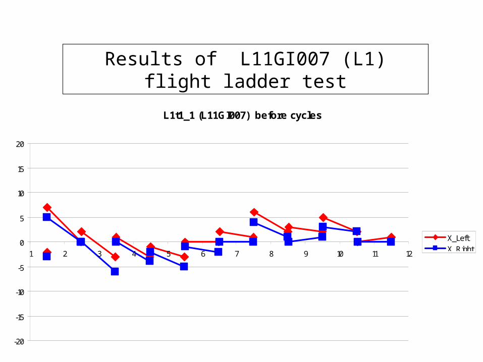
L1t1_1 (L11GI007) before cycles
-20
-15
-10
-5
0
5
10
15
20
1 2 3 4 5 6 7 8 9 10 11 12X_LeftX_Right
Results of L11GI007 (L1) flight ladder test

L1t1_1 (L11GI007) before cycles
-20
-15
-10
-5
0
5
10
15
20
1 2 3 4 5 6 7 8 9 10 11 12Y_LeftY_Right

L1t1_1 (L11GI007) before cycles
-150
-100
-50
0
50
100
150
1 2 3 4 5 6 7 8 9 10 11 12Z_LeftZ_Right

L1t1_2 - L1t1_1 (L11GI007) Delta after -20deg cycles
-5
-4
-3
-2
-1
0
1
2
3
4
5
1 2 3 4 5 6 7 8 9 10 11 12X_LeftX_Right

L1t1_2 - L1t1_1 (L11GI007) Delta after -20deg cycles
-5
-4
-3
-2
-1
0
1
2
3
4
5
1 2 3 4 5 6 7 8 9 10 11 12Y_LeftY_Right

L1t1_2 - L1t1_1 (L11GI007) Delta after -20deg cycles
-10
-8
-6
-4
-2
0
2
4
6
8
10
1 2 3 4 5 6 7 8 9 10 11 12Z_LeftZ_Right


L1t1_3 - L1t1_2 (L11GI007) Delta after post-20deg pull-out
-5
-4
-3
-2
-1
0
1
2
3
4
5
1 2 3 4 5 6 7 8 9 10 11 12X_LeftX_Right
L1t1_3 - L1t1_2 (L11GI007) Delta after post-20deg pull-out
-10
-8
-6
-4
-2
0
2
4
6
8
10
1 2 3 4 5 6 7 8 9 10 11 12Z_LeftZ_Right
L1t1_3 - L1t1_2 (L11GI007) Delta after post-20deg pull-out
-5
-4
-3
-2
-1
0
1
2
3
4
5
1 2 3 4 5 6 7 8 9 10 11 12Y_LeftY_Right

L1t2_1 - L1t1_3 (L11GI007) Delta after -30deg cycles
-5
-4
-3
-2
-1
0
1
2
3
4
5
1 2 3 4 5 6 7 8 9 10 11 12X_LeftX_Right
L1t2_1 - L1t1_3 (L11GI007) Delta after -30deg cycles
-5
-4
-3
-2
-1
0
1
2
3
4
5
1 2 3 4 5 6 7 8 9 10 11 12Y_LeftY_Right
L1t2_1 - L1t1_3 (L11GI007) Delta after -30deg cycles
-10
-8
-6
-4
-2
0
2
4
6
8
10
1 2 3 4 5 6 7 8 9 10 11 12Z_LeftZ_Right

L1t2_2 - L1t2_1 (L11GI007) Delta after 2 N pull test
-5
-4
-3
-2
-1
0
1
2
3
4
5
1 2 3 4 5 6 7 8 9 10 11 12X_LeftX_Right
L1t2_2 - L1t2_1 (L11GI007) Delta after 2 N pull test
-5
-4
-3
-2
-1
0
1
2
3
4
5
1 2 3 4 5 6 7 8 9 10 11 12Y_LeftY_Right
L1t2_2 - L1t2_1 (L11GI007) Delta after 2 N pull test
-10
-8
-6
-4
-2
0
2
4
6
8
10
1 2 3 4 5 6 7 8 9 10 11 12Z_LeftZ_Right
post -30deg

L1t3_1 - L1t2_3 (L11GI007) Delta after -40deg cycles
-5
-4
-3
-2
-1
0
1
2
3
4
5
1 2 3 4 5 6 7 8 9 10 11 12X_LeftX_Right
L1t3_1 - L1t2_3 (L11GI007) Delta after -40deg cycles
-5
-4
-3
-2
-1
0
1
2
3
4
5
1 2 3 4 5 6 7 8 9 10 11 12Y_LeftY_Right
L1t3_1 - L1t2_3 (L11GI007) Delta after -40deg cycles
-14-12-10-8-6-4-20246810
1 2 3 4 5 6 7 8 9 10 11 12 Z_LeftZ_Right
Deltas after -40deg cycles

L1t3_6up-L1t3_5up 21-sep Delta after pull
-5
-4
-3
-2
-1
0
1
2
3
4
5
1 2 3 4 5 6 7 8 9 10 11 12X_LeftX_Right
L1t3_6up-L1t3_5up 21-sep Delta after pull
-5
-4
-3
-2
-1
0
1
2
3
4
5
1 2 3 4 5 6 7 8 9 10 11 12Y_LeftY_Right
Post -40deg Delta after pull (upper part)L1t3_6up-L1t3_5up 21-sep Delta after pull
-10
-8
-6
-4
-2
0
2
4
6
8
10
1 2 3 4 5 6 7 8 9 10 11 12Z_LeftZ_Right

L1t3_7up-L1t3_7up 21-24sep Delta after push
-5
-4
-3
-2
-1
0
1
2
3
4
5
1 2 3 4 5 6 7 8 9 10 11 12X_LeftX_Right
L1t3_7up-L1t3_7up 21-24sep Delta after push
-5
-4
-3
-2
-1
0
1
2
3
4
5
1 2 3 4 5 6 7 8 9 10 11 12Y_LeftY_Right
Push test L1t3_7up-L1t3_7up 21-24sep Delta after push
-10
-8
-6
-4
-2
0
2
4
6
8
10
1 2 3 4 5 6 7 8 9 10 11 12Z_LeftZ_Right

SUMMARY & CONCLUSION
• Two ladders tested (1 mech.proto, 1 flight )
• 60 cycles = 4 [cycle/year] x 15 years (-20, -30, -40)
• Up to now, no mechanical integrity problems have been seen (geometry, solidity, micro-bonds) by D.R.
• Electrical behavior (specially FE hybrids) not tested
• Geometry .vs. Temperature not tested yet
• Strain gauges study still in progress


spare slides

First estimate on Ladder temperature for one ladder in plane 1
-18°C on the worst silicon wafer!
Emissivity are different on both sides:• -20 °C max to the Tracker support, em.=0.9• 0°C to the TRD top side, em.=0.1
Preliminary
Franck Cadoux december 2011

First estimate on Ladder deflection: everything @ -20°C (homogeneous)
Uvert.= -74 microns
Ulong.= -94 microns
Preliminarydepends on thickness and surface of glue
140 microns

First estimate on mechanical stresses @ -20°C
No issue / silicon(7 Mpa)
Preliminary

First estimate on mechanical stresses @ -20°C
Stress @ glue joint:18 MPa (VMises; peak value) Shear Stress @ glue joint:
10 MPa (peak value)
Epoxy shear strength is given at10Mpa (without post curing operation!)
Preliminarydepends on the amount of glue


![Measurement of the e Cross Section and the W …dpnc.unige.ch/THESES/DELMEIRE_these.pdfneutrinos au LEP exclut une quatri eme famille de neutrinos l egers: N = 2:994 0:012 [3] Le boson](https://img.pdfslide.us/doc/110x75/5eb95c6ef9db9f34db022c04/measurement-of-the-e-cross-section-and-the-w-dpncunigechthesesdelmeirethesepdf.jpg)
![onflits d’intérêts aadémiques - [Institut Maurice Rapin] · - Marcia Angell (2004) Random House Publisher NY - Heichacker et Natanson NEJM 2010 - Ch Wiedermann (2005) Wien Klin](https://img.pdfslide.us/doc/110x75/5bfaea6509d3f2762a8bea96/onflits-dinterets-aademiques-institut-maurice-rapin-marcia-angell.jpg)