Embed Size (px)
Citation preview
NASA Technical Memorandum 1021 1 1
Diamondlike Carbon Protective Coatings for Optical Windows
Diane M. Swec and Michael J. Mirtich Lewis Research Center Cleveland, Ohio
Prepared for the 1989 Technical Symposia on Aerospace Sensing sponsored by The International Society for Optical Engineering Orlando, Florida, March 27-3 1, 1989
IlJASA-TH-1021 I ? ) DIABONDLIKE CAREON PBOTECTIVE COATIblCS FOR OPTICAL ZlIIDOClS (HASA. L e w i s Research Center) 16 pCSCL 20E
- 18 9- 2 7506
Unclas G3/74 10224122
https://ntrs.nasa.gov/search.jsp?R=19890018135 2018-06-20T16:44:28+00:00Z
DIAMONDLIKE CARBON PROTECTIVE COATINGS FOR OPTICAL WINDOWS
Diane M. Swec and M ichae l J . M i r t i c h N a t i o n a l A e r o n a u t i c s and Space Admini s t r a t i o n
Lewis Research Center C l e v e l a n d , O h i o 44135
SUMMARY
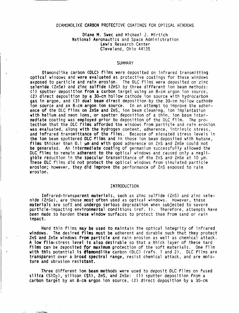
D i a m o n d l i k e carbon (DLC) f i l m s were d e p o s i t e d on i n f r a r e d t r a n s m i t t i n g o p t i c a l windows and were e v a l u a t e d as p r o t e c t i v e c o a t i n g s f o r these windows exposed t o p a r t i c l e and r a i n e r o s i o n . The DLC f i l m s were d e p o s i t e d on z i n c s e l e n i d e (ZnSe) and z l n c s u l f i d e (ZnS) by t h r e e d i f f e r e n t i o n beam methods: ( 1 ) s p u t t e r d e p o s i t i o n from a carbon t a r g e t u s i n g an 8-cm argon i o n source , ( 2 ) d i r e c t deposi t l o n by a 30-cm h o l l o w cathode i o n source w i t h hydrocarbon gas i n a rgon, and ( 3 ) dua l beam d i r e c t d e p o s i t i o n by t h e 30-cm h o l l o w cathode i o n source and an 8-cm argon i o n source . I n an a t t e m p t t o improve t h e adher- ence o f t h e DLC f i l m s on ZnSe and ZnS, i o n beam c l e a n i n g , i o n i m p l a n t a t i o n w i t h h e l i u m and neon i o n s , or s p u t t e r d e p o s i t i o n o f a t h i n , i o n beam i n t e r - med ia te c o a t i n g was employed p r i o r t o d e p o s i t i o n o f t h e DLC f i l m . The p ro - t e c t i o n t h a t t h e DLC f i l m s a f f o r d e d t h e windows from D a r t i c l e and r a i n e r o s i o n was eva lua ted , a l o n g w i t h t h e hydrogen c o n t e n t , adherence, i n t r i n s i c s t r e s s , and i n f r a r e d t r a n s m i t t a n c e o f t h e f i l m s . Because o f e l e v a t e d s t r e s s l e v e l s t h e i o n beam s p u t t e r e d DLC f i l m s and i n those i o n beam d e p o s i t e d w i t h bu tane f i l m s t h i c k e r t h a n 0.1 pm and w i t h good adherence on ZnS and ZnSe c o u l d n o t be genera ted . An i n t e r m e d i a t e c o a t i n g o f germanium s u c c e s s f u l l y a l l o w e d t h e DLC f i l m s t o remain a d h e r e n t to t h e o p t i c a l windows and caused o n l y a n e g l i - g i b l e r e d u c t i o n i n the s p e c u l a r t r a n s m i t t a n c e o f t h e ZnS and ZnSe a t 10 pn. These DLC f i l m s d i d n o t p r o t e c t t h e o p t i c a l windows from s i m u l a t e d p a r t i c l e e r o s i o n ; however, t h e y d i d improve t h e per formance o f ZnS exposed t o r a i n e ros i on.
n
INTRODUCTION
I n f r a r e d - t r a n s p a r e n t m a t e r i a l s , such as z i n c s u l f i d e (ZnS) and z i n c s e l e - n i d e (ZnSe), a r e those most o f t e n used as o p t i c a l windows. However , t h e s e m a t e r i a l s a r e soft and undergo s e r i o u s d e g r a d a t i o n when s u b j e c t e d t o severe p a r t i c l e - i m p a c t i n g e n v i r o n m e n t a l c o n d i t i o n s ( r e f . 1 ) . There fore , a t t e m p t s have been made t o harden these window s u r f a c e s t o p r o t e c t them from sand or r a i n impact .
Hard t h i n f i l m s may be used t o m a i n t a i n t h e o p t i c a l i n t e g r i t y o f i n f r a r e d windows. The d e s i r e d f i l m s must be a d h e r e n t and d u r a b l e such t h a t t h e y p r o t e c t ZnS and ZnSe windows from p a r t i c l e and r a i n e r o s i o n as w e l l as chemica l a t t a c k . A low f i l m - s t r e s s l e v e l Is a l s o d e s i r a b l e so t h a t a t h i c k l a y e r o f these ha rd f i l m s can be d e p o s i t e d for maximum p r o t e c t i o n o f t h e so f t m a t e r i a l s . One f i l m w i th t h i s p o t e n t i a l I s &$amondl ike carbon (DLC) ( r e f s . 1 and 2 ) . DLC f i l m s a r e t r a n s p a r e n t o v e r a broad s p e c t r a l range, r e s i s t chemical a t t a c k , and a r e mois- t u r e and a b r a s i o n r e s i s t a n t .
Three d i f f e r e n t ion beam methods were used t o d e p o s i t DLC f i l m s on f u s e d s i l i c a (SiO2>, s i l i c o n ( S I ) , ZnS, and ZnSe: carbon t a r g e t by an 8-cm argon Ion source , ( 2 ) d i r e c t d e p o s i t i o n by a 30-cm
( 1 ) s p u t t e r d e p o s i t i o n from a
h o l l o w cathode i o n source w i t h hydrocarbon gas i n a rgon ( A r ) , and (3) dua l beam d i r e c t d e p o s i t i o n by t h e 30-cm h o l l o w cathode and an 8-cm argon i o n source . To improve t h e adherence o f t h e DLC f i l m s on ZnS and ZnSe, t h e f o l l o w i n g t e c h - n iques were employed p r i o r t o d e p o s i t i o n o f t h e f i l m : ( 2 ) i o n i m p l a n t a t i o n v i a "knock on" o f t h i n carbon f i l m s by 100-keV n i t r o g e n i o n s , ( 3 ) i o n i m p l a n t a t i o n w i t h 100-keV neon and h e l i u m i o n s , and (4 ) t h i n , i o n beam s p u t t e r - d e p o s i t e d i n t e r m e d i a t e c o a t i n g s o f germanium (Ge) or s i l i c o n . The DLC f i l m s were t h e n e v a l u a t e d f o r hydrogen c o n t e n t , adherence, i n t r i n s i c s t r e s s , i n f r a r e d t r a n s m i t t a n c e , and p r o t e c t i o n from p a r t i c l e and r a i n e r o s i o n . An e r o s i o n t e s t employ ing a m i c r o s a n d b l a s t e r w i t h 27-pm-diameter aluminum o x i d e (A12031 p a r t i c l e s was deve loped t o d e t e r m i n e q u a n t i t a t i v e v a l u e s o f t h e p r o t e c t i o n t h a t t h e d i a m o n d l i k e f i l m s a f f o r d e d t h e window s u r f a c e s . A f t e r e r o s i o n an i n f r a r e d ( I R ) spec t rophotometer was used t o i n d i c a t e t h e change i n s p e c u l a r t r a n s m i t t a n c e between 2 . 5 and 50 pm. The DLC-coated windows were a l s o s u b j e c t e d t o water d r o p l e t s a t 180 m/sec f o r exposure t i m e s up t o 15 min i n a r a i n e r o s i o n f a c i l i t y a t W r i g h t P a t t e r s o n A i r Force Base. These samples were q u a l i t a t i v e l y e v a l u a t e d by o p t i c a l l y v i e w i n g t h e p i t t i n g , m i c r o c r a c k s , and subsur face r i n g c r a c k s t h a t r e s u l t e d from t h e e r o s i o n . The r e s u l t s o f these s t u d i e s a r e p r e s e n t e d i n t h i s paper .
( 1 ) i o n beam c l e a n i n g ,
APPARATUS AND PROCEDURE
D iamond l ike carbon f i l m s were i o n beam s p u t t e r d e p o s i t e d from a p y r o l y t i c g r a p h i t e t a r g e t b y an 8-cm-diameter source ( r e f . 3 ) . A 1000-eV argon i o n beam was produced for s p u t t e r c l e a n i n g and d e p o s i t i o n . was -1.0 mA/cm2 i n t h e v i c i n i t y of t h e s p u t t e r t a r g e t and s u b s t r a t e s , wh ich were l o c a t e d 20 cm downstream o f t h e i o n source . The i o n source was o p e r a t e d w i t h a h o t f i l a m e n t n e u t r a l i z e r i n a vacuum f a c i l i t y t h a t m a i n t a i n e d p r e s s u r e s o f 2x10⁻⁵ t o r r d u r i n g o p e r a t i o n . I n c o n j u n c t i o n w i t h t h i s method, hydrogen gas was i n t r o d u c e d i n t h e vacuum chamber t o e v a l u a t e i t s e f f e c t on t h e s e f i l m s . The i n t r o d u c t i o n o f hydrogen gas r a i s e d t h e background p r e s s u r e t o a range of 7x10⁻⁵ t o 10-4 t o r r . F i l m s 0.1 pm t h i c k were d e p o s i t e d on t h e v a r i o u s sub- s t r a t e s .
The i o n beam c u r r e n t d e n s i t y
A 30-cm-diameter i o n source w i t h i t s o p t i c s masked t o 10 cm i n d i a m e t e r was used t o d i r e c t l y d e p o s i t t h e DLC f i l m s ( r e f . 4 ) . The i o n source used argon gas i n t h e h o l l o w cathode l o c a t e d i n t h e main d i s c h a r g e chamber, as w e l l as i n t h e n e u t r a l i z e r . Hydrocarbon gas was i n t r o d u c e d t h r o u g h a m a n i f o l d i n t o t h e d i s c h a r g e chamber a t a m o l a r r a t i o o f 0 . 2 8 CH4 or 0.10 C4H10 t o argon. T y p i c a l l y , c u r r e n t d e n s i t i e s were 1 mA/cm2 a t a d i s t a n c e o f 2 . 5 cm a x i a l l y downstream o f t h e g r i d s , and argon i o n e n e r g i e s ranged from 90 t o 250 e V .
I t i s b e l i e v e d t h a t amorphous carbon f i l m s a r e produced under c o n d i t i o n s where growth and s p u t t e r i n g o c c u r s i m u l t a n e o u s l y , t h e r e f o r e i n c r e a s e d s p u t t e r - i n g may decrease t h e number o f g r a p h i t e p r e c u r s o r s i n c o r p o r a t e d i n t h e f i l m s and hence improve t h e q u a l i t y ( r e f . 4 ) . An 8-cm ion source w i t h a f i l a m e n t cathode was used d u r i n g t h e dua l beam d e p o s i t i o n t o d i r e c t a beam o f 200- t o 600-eV argon i o n s a t a c u r r e n t d e n s i t y o f 25 pA/cm2 on t h e s u b s t r a t e s w h i l e t h e DLC f i l m was b e i n g d e p o s i t e d by t h e 30-cm source .
The i n t r i n s i c s t r e s s o f t h e DLC f i l m s was measured w i t h a s t r e s s gauge, and an adherence t e s t e r was used t o d e t e r m i n e t h e adherence o f t h e DLC f i l m s . The t r a n s m i t t a n c e o f t h e DLC f i l m s i n t h e v i s i b l e r e g i o n was o b t a i n e d w i t h an i n t e - g r a t i n g sphere, and t h e IR t r a n s m i t t a n c e was measured w i t h a s p e c t r o p h o t o m e t e r .
2
An erosion test was developed that used a sandblaster to give quantitative values to the protection that the DLC films afforded fused silica (ref. 5 ) . The fused silica surfaces were exposed to 100-pm-diameter Si02 particles at 2 7 m/sec, and then the protective quality of the film was characterized by the resulting change in specular transmittance by a neon-helium ellipsometer. The protection that the DLC films afforded the ZnS and ZnSe surfaces was quantita- tively determined from another simulated particle erosion test (ref. 6). wlndow surfaces were eroded by exposing them to 27-pm-diameter A1203 particles with an estimated stream velocity of 335 m/sec in a microsandblaster. protective quality of the film was then characterized by the change in specular transmittance due to the particle erosion with an IR spectrophotometer between wavelengths of 2 . 5 and 50 pm.
The
The
‘ A facility at the Wright Patterson Air Force Base was employed to evaluate the rain erosion performance of the DLC films. The rain erosion facility con- sisted of a variable-speed rotating arm apparatus with speeds to 210 m/sec and a simulated rainfall of 7x10⁻⁴ cm/sec. The rotating arm apparatus employed a horizontally mounted, 8-ft double-arm propeller blade powered by a 400-hp motor. trolled water droplets were sprayed on the test specimens, which were mounted in the blade tips.
A pipe ring containing hypodermic needles was positioned such that con-
RESULTS AND DISCUSSION
Hydrogen Content
Nuclear reaction and combustion analysis for hydrogen was performed on the
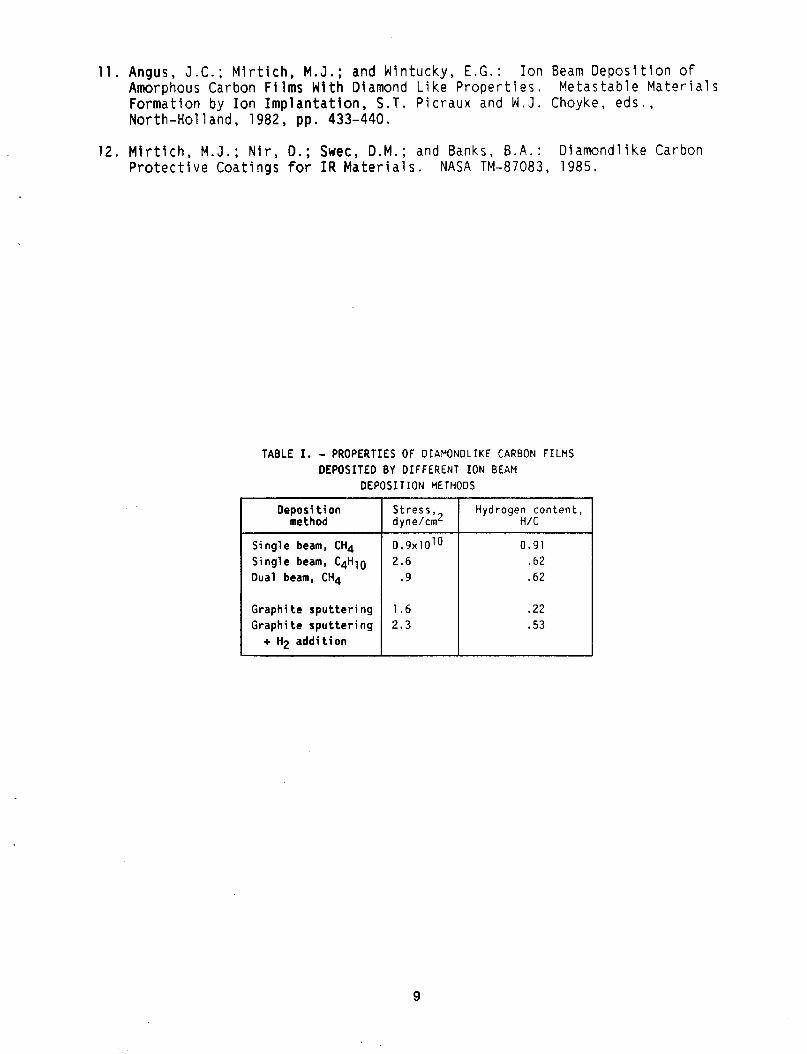
The atomic ratio DLC films (ref. 7 ) . This technique showed that DLC films made by the various deposition methods have very similar hydrogen depth profiles. of hydrogen to carbon ( H K ) was low at the film surface and rose to a constant value at a depth of 50 nm. Table I shows the hydrogen-to-carbon ratios meas- ured one-half of the distance through the DLC films for the three different deposition methods. There i s a variation in hydrogen content which depends on the method used to deposit the DLC film. DLC films made by single ion-beam deposition with CH4 had an H/C ratio of 0.91. Adding the energy of the second ion source (dual beam) reduced this ratio to 0.62. Thus, the second source removed some of the hydrogen. DLC films generated by the single source, but with C4H10, also had an H/C ratio of 0.62. The films generated by ion beam sputter deposition from a graphite target contained the least amount of hydro- gen, an H / C ratio of 0.22. The addition of up to 35 percent hydrogen gas into the vacuum facility during sputter deposition doubled the hydrogen content of these films.
Semiquantitative Infrared spectroscopy was also performed on these ion beam deposited films. The Integrated intensity of the C-H stretching band at about 3 . 4 pm indicated that the ratio of chemically bonded hydrogen to carbon was between 0.03 and 0.44 (ref. 7 ) . The difference between the two hydrogen analysi s techniques indicates the presence of nonbonded hydrogen in the f i lms.
3
I n t r i n s i c S t r e s s
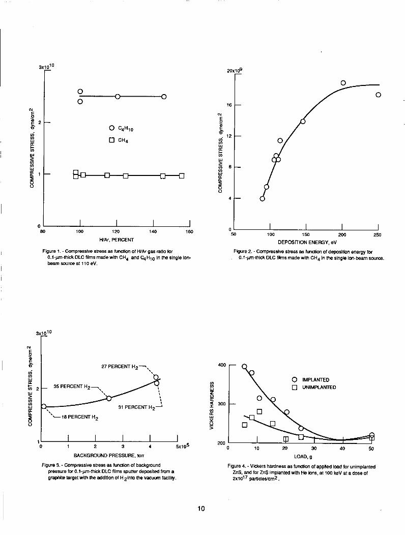
The DLC f i l m s d e p o s i t e d on S i e x h i b i t e d a compress ive s t r e s s t h a t v a r i e d depending on t h e d e p o s i t i o n method, hydrocarbon gas, and energy o f d e p o s i t i o n . F i g u r e s 1 t o 3 show t h e s t r e s s l e v e l s o f 0.1-pm-th ick DLC f i l m s made by t h e d i f f e r e n t i o n beam d e p o s i t i o n methods. F i g u r e 1 i s a p l o t o f t h e compress ive s t r e s s as a f u n c t i o n o f t h e H / A r gas r a t i o for CH4 and C4H10 gases d e p o s i t e d a t 110 eV by t h e s i n g l e ion-beam source . The s t r e s s fo r each t y p e of f i l m was independent o f t h e H l A r r a t i o , b u t was 2 . 5 t imes as l a r g e for t h e C4H10 f i l m s as i t was f o r t h e CH4 f i l m s . F i g u r e 2 shows t h a t t h e s t r e s s i n t h e CH4 s i n g l e beam f i l m s can be reduced to v a l u e s as low as 4x10⁹ dynelcm2 b y d e c r e a s i n g t h e d e p o s i t i o n energy t o 90 e V . F i g u r e 3 shows t h e compress ive s t r e s s f o r DLC f i l m s d e p o s i t e d by i o n s p u t t e r i n g a g r a p h i t e t a r g e t ( i n c l u d i n g those f i l m s made w i t h t h e a d d i t i o n o f hydrogen) . The compress ive s t r e s s was 1 . 6 ~ 1 0 1 0 dynelcm2 f o r a pure , s p u t t e r - d e p o s i t e d f i l m and rose s l i g h t l y t o 2 . 3 ~ 1 0 ' 0 dynelcm2 f o r a f i l m w i t h hydrogen a d d i t i o n . These s t r e s s l e v e l s a r e h i g h e r t h a n t h o s e f o r f i l m s made b y d i r e c t i o n beam d e p o s i t i o n , s i n g l e or d u a l , w i t h CH4. T a b l e I l i s t s t h e s t r e s s l e v e l s fo r t h e v a r i o u s DLC f i l m s . The d a t a i n d i c a t e t h a t t h e f i l m s t r e s s does n o t depend on t h e hydrogen c o n t e n t , b u t on o t h e r parameters such as d e p o s i t i o n t e c h n i q u e and c o n d i t i o n s , and hydrocarbon gas.
Adherence
The adherence of t h e DLC f i l m s on fused s i l i c a was measured by f o l l o w i n g t h e procedure used by M i r t i c h ( r e f . 8). F i l m s up t o 1 pm t h i c k , d e p o s i t e d b y e i t h e r s i n g l e or d u a l beam systems w i t h CH4, were a t l e a s t as a d h e r e n t as t h e maximum measurable adherence o f t h e t e s t e r : namely, 2 . 8 ~ 1 0 6 N / d . These f i l m s were so adherent t h a t , for some o f t h e f i l m s , p o r t i o n s o f t h e S i 0 2 gave way w i t h t h e f i l m s t i l l i n t a c t . f i l m s made by t h e s i n g l e ion-beam system w i t h C4H10 began t o s p a l l once t h e t h i c k n e s s reached 0.15 pm, and t h e f i l m s t h a t were s p u t t e r d e p o s i t e d from t h e g r a p h i t e t a r g e t began t o s p a l l a t 0.2 pm t h i c k , i n d i c a t i n g an upper l i m i t o f t h e a l l o w a b l e t h i c k n e s s o f t h e s e f i l m s . T h i s was expec ted , s i n c e t h e s t r e s s l e v e l s o f these two t y p e s o f DLC f i l m s were g r e a t e r t h a n those made w i t h CH4 i n e i t h e r t h e s i n g l e or dua l beam.
I n an a t t e m p t t o improve t h e adherence o f DLC f i l m s t h a t were i o n beam d e p o s i t e d on ZnS and ZnSe, f o u r t e c h n i q u e s were used p r i o r t o f i l m d e p o s i t i o n ( r e f . 9 ) . I o n beam c l e a n i n g o f t h e window m a t e r i a l s was t h e f i rst t e c h n i q u e used, b u t was n o t s u f f i c i e n t , as i t was w i t h t h e S i 0 2 or S i s u b s t r a t e s , t o a l l o w t h e DLC f i l m s t o remain a d h e r e n t . The f i l m s had n e g l i g i b l e adherence (<1 .4x104 N/m2> and spa1 l e d a l m o s t i m m e d i a t e l y a f t e r d e p o s i t i o n on b o t h ZnS and ZnSe. The second t e c h n i q u e i n v o l v e d i o n i m p l a n t a t i o n v i a "knock o n " o f t h i n carbon f i l m s on t h e s u r f a c e of ZnS and ZnSe by 50 t o 100 keV n i t r o g e n i o n s . T h i s t e c h n i q u e a l s o f a i l e d t o a l l o w t h e DLC f i l m s t o remain a d h e r e n t . I n t h e t h i r d t e c h n i q u e , t h e window sur faces were i o n i m p l a n t e d w i t h neon or h e l i u m a t e n e r g i e s v a r i n g between 50 and 100 keV and a t doses from 0 . 5 ~ 1 0 ~ ~ t o 2x10¹⁷ p a r t i c l e s l c m j . These f i l m s s p a l l e d a f t e r a p e r i o d o f t i m e . The f o u r t h t e c h n i q u e , which used a t h i n i n t e r m e d i a t e c o a t i n g o f germanium or s i l i - con, s u c c e s s f u l l y a l l o w e d t h e DLC f i l m s t o remain a d h e r e n t . T h i n f i l m s o f Ge or S i , 0.1 pm t h i c k , were i o n beam s p u t t e r d e p o s i t e d o n t o ZnS and ZnSe p r i o r t o d e p o s i t i o n o f DLC. The i n t e r f a c e of S i looked good on d e p o s i t , b u t s p a l l e d as a f u n c t i o n o f t i m e a n d / o r t h i c k n e s s . Germanium f i l m s as t h i c k as 0.4 pm
4
e x h i b i t e d adherence equal to t h e s t r e n g t h o f t h e s u b s t r a t e and showed no s i g n o f d e t e r i o r a t i o n even a f t e r 6 months. DLC f i l m s d e p o s i t e d on ZnS and ZnSe w i t h an i n t e r m e d i a t e Ge c o a t i n g of 0,,05 pm showed adherence va lues o f 106 t o 1 . 4 ~ 1 0 6 N/m2, a l s o equal to t h e s t r e n g t h o f t h e s u b s t r a t e . s i b l e to o b t a i n t h e same adherence va lues o f DLC-Ge f i l m s d e p o s i t e d on ZnS and ZnSe s u b s t r a t e s t h a t were first Imp lan ted w i t h 100-keV He i o n s a t doses t o 2x1 017 p a r t i c l eslcm2.
I t was a l s o pos-
A bonus o f i o n i m p l a n t a t i o n was t h e improved p h y s i c a l hardness o f t h e sub- s t r a t e , shown i n f i g u r e 4 for ZnS. The V i c k e r s hardness as a f u n c t i o n o f t h e a p p l i e d l o a d f o r u n i m p l a n t e d ZnS and ZnSe was compared w i t h t h a t f o r ZnS and ZnSe t h a t were He i o n imp lan ted a t 100 keV a t a dose equal t o 2x10¹⁷ p a r t i c l e s / c m 2 . A t t h e 5-g i n d e n t o r l oad , t h e s u r f a c e hardness fo r t h e imp lan ted ZnS shows a d r a m a t i c 70 pe rcen t i n c r e a s e o v e r t h e u n i m p l a n t e d ZnS.
T r a n s m i t t a n c e
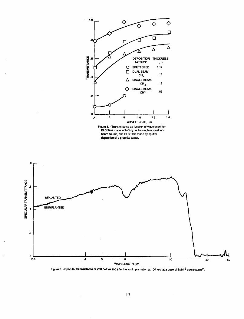
The t r a n s m i t t a n c e o f t h e DLC f i l m s on f u s e d s i l i c a i n t h e v i s i b l e r e g i o n was o b t a i n e d by u s i n g t h e Bowman t e c h n i q u e ( r e f . 10 ) . The DLC f i l m s o b t a i n e d from t h e s i n g l e ion-beam d e p o s i t i o n method w i t h CH4 have a s p e c t r a l t r a n s m i t - tance s i m i l a r t o those genera ted by t h e dua l beam source, b u t t h e s i n g l e beam f i l m s have lower t r a n s m i t t a n c e va lues when t h e y a r e g r e a t e r t han 0.12 pm t h i c k . T h i s i s e v i d e n t i n f i g u r e 5, where t h e s p e c t r a l t r a n s m i t t a n c e i s shown for DLC f i l m s , 0.15 pm t h i c k , genera ted by b o t h methods. The 0 .15-pm- th ick dua l beam f i l m has g r e a t e r t r a n s m i t t a n c e a t a l l wavelengths when compared w i t h t h e s i n g l e beam f i l m o f t h e same t h i c k n e s s . The inc reased a b s o r p t i o n most l i k e l y a r i s e s from t h e presence of systems o f c o n j u g a t e d doub le bonds w i t h i n t h e f i l m , a l t h o u g h t h e presence o f oxygen c o u l d a l s o p l a y a ro le ( r e f . 1 1 ) . Bo th t h e g r a p h i t i c p r e c u r s o r s and t h e oxygen would be expec ted t o be reduced by t h e i nc reased s p u t t e r i n g from t h e second source . A 0.05-pm- th ick DLC f i l m t h a t was s i n g l e ion-beam d e p o s i t e d f r o m CH4 d i s p l a y s s p e c t r a l t r a n s m i t - t ance va lues g r e a t e r t han 90 p e r c e n t a t wavelengths g r e a t e r t han 0.8 pm. F i g u r e 5 a l s o shows s p e c t r a l d a t a for a 0.17-pm-th ick DLC f i l m t h a t was i o n beam s p u t t e r d e p o s i t e d from a g r a p h i t e t a r g e t . o n l y between 0 .4 and 0.8 pm for t h i s f i l m , and i t i s v e r y low compared w i t h t h e DLC f i l m s t h a t were d i r e c t d e p o s i t e d . The low t r a n s m i t t a n c e o f t h e spu t - t e r e d f i l m may be due t o i t s low hydrogen c o n t e n t .
The t r a n s m i t t a n c e was measured
The DLC f i l m s d e p o s i t e d on S i s u b s t r a t e s a c t e d as a n t i r e f l e c t i v e c o a t i n g s , enhanc ing t h e i n f r a r e d t r a n s m i t t a n c e t h a t was g r e a t e s t a t s h o r t e r wave lengths and t h a t decreased w l t h i n c r e a s i n g wave length . T h i s a n t i r e f l e c t i v e p r o p e r t y was observed f o r a l l o f t h e DLC f i l m s d e p o s i t e d on S i , and t h e r e f o r e was inde- pendent o f d e p o s i t i o n method.
A spec t rophotometer was used t o measure t h e I R t r a n s m i t t a n c e o f t h e DLC f i l m s d e p o s i t e d on t h e ZnS and ZnSe, s u b s t r a t e s . The s p e c t r a l t r a n s m i t t a n c e o f t h e window m a t e r i a l d i d not change I n t h e wave length r e g i o n o f 2 . 5 t o 25 pm f o r t h e ZnS and ZnSe substrates coated w i t h 0 - 1 - p m - t h i c k DLC f i l m s . The use of an i n t e r m e d i a t e Ge f i l m or ion I m p l a n t a t i o n a l s o d i d n o t change t h e I R t r a n s m l t t a n c e of ZnS and ZnSe. F I g u r e 6 shows t h e specu la r I R t r a n s m i t t a n c e of ZnS b e f o r e and a f t e r Implantat ion w i t h 100-keV He i o n s a t a dose o f 5 ~ 1 0 ~ 6 p a r t i c l e s / c d . The two t r a c e s f a l l on t o p o f each o t h e r , i n d i c a t i n g t h a t t h e r e i s no v a r i a t i o n i n t h e I R s p e c u l a r t r a n s m i t t a n c e o f ZnS a f t e r exposure t o
5
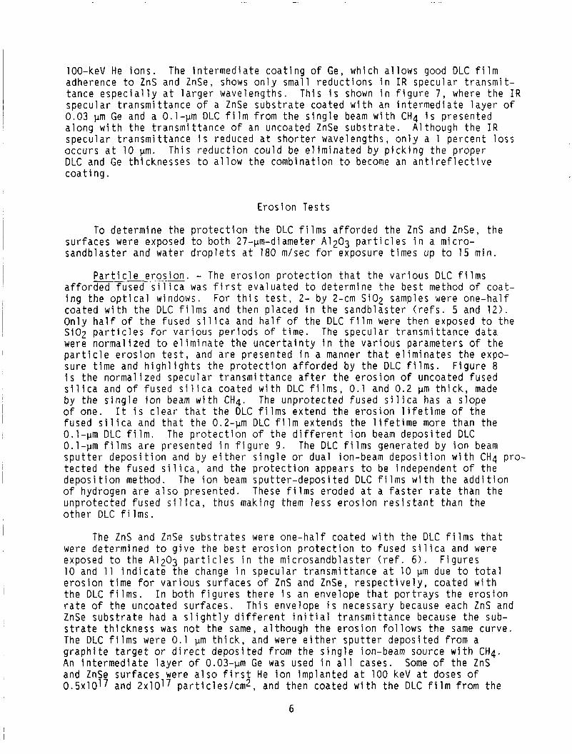
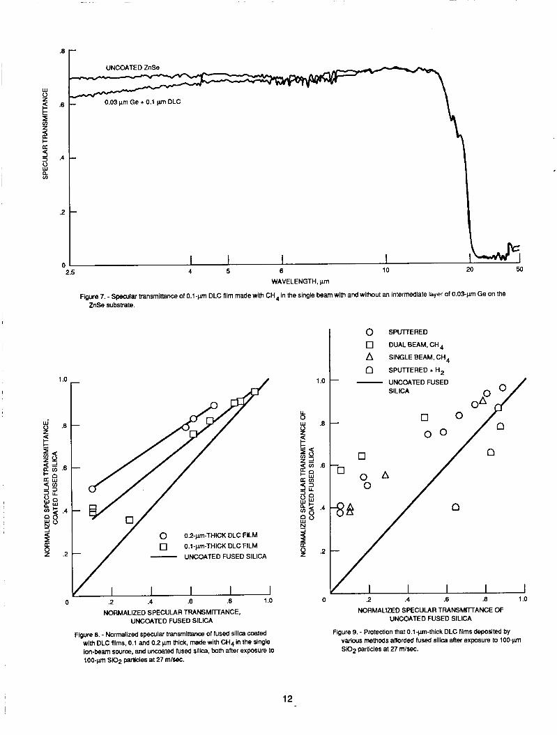
100-keV He i o n s . The i n t e r m e d i a t e c o a t i n g o f Ge, which a l l o w s good DLC f i l m adherence t o ZnS and ZnSe, shows o n l y smal l r e d u c t i o n s i n I R s p e c u l a r t r a n s m i t - t a n c e e s p e c i a l l y a t l a r g e r wave lengths . T h i s i s shown i n f i g u r e 7, where t h e I R s p e c u l a r t r a n s m i t t a n c e o f a ZnSe s u b s t r a t e coated w i t h an i n t e r m e d i a t e l a y e r o f 0 .03 pm Ge and a 0.1-pm DLC f i l m from t h e s i n g l e beam w i t h CH4 i s p r e s e n t e d a l o n g w i t h t h e t r a n s m i t t a n c e of an uncoated ZnSe s u b s t r a t e . A l t h o u g h t h e I R s p e c u l a r t r a n s m i t t a n c e i s reduced a t s h o r t e r wave lengths , o n l y a 1 p e r c e n t loss o c c u r s a t 10 pm. T h i s r e d u c t i o n c o u l d be e l i m i n a t e d b y p i c k i n g t h e p r o p e r DLC and Ge t h i c k n e s s e s t o a l l o w t h e c o m b i n a t i o n t o become an a n t i r e f l e c t i v e c o a t i ng .
E r o s i o n Tes ts
To d e t e r m i n e t h e p r o t e c t i o n t h e DLC f i l m s a f f o r d e d t h e ZnS and ZnSe, t h e s u r f a c e s were exposed t o b o t h 27-pm-diameter A1203 p a r t i c l e s i n a micro- s a n d b l a s t e r and water d r o p l e t s a t 180 m/sec f o r exposure t imes up to 15 min .
P a r t i c l e e r o s i o n . - The e r o s i o n p r o t e c t i o n t h a t t h e v a r i o u s DLC f i l m s a f f o r d e d f u s e d s i l i c a was f i r s t e v a l u a t e d t o de termine t h e b e s t method o f c o a t - i n g t h e o p t i c a l windows. For t h i s t e s t , 2- by 2-cm S i02 samples were o n e - h a l f coa ted w i t h t h e DLC f i l m s and t h e n p l a c e d i n t h e s a n d b l a s t e r ( r e f s . 5 and 1 2 ) . O n l y h a l f o f t h e f u s e d s i l i c a and h a l f o f t h e DLC f i l m were t h e n exposed t o t h e S i 0 2 p a r t i c l e s f o r v a r i o u s p e r i o d s of t i m e . The s p e c u l a r t r a n s m i t t a n c e d a t a were n o r m a l i z e d to e l i m i n a t e t h e u n c e r t a i n t y i n t h e v a r i o u s parameters o f t h e p a r t i c l e e r o s i o n t e s t , and a r e p r e s e n t e d i n a manner t h a t e l i m i n a t e s t h e expo- s u r e t i m e and h i g h l i g h t s t h e p r o t e c t i o n a f f o r d e d by t h e DLC f i l m s . F i g u r e 8 i s t h e n o r m a l i z e d s p e c u l a r t r a n s m i t t a n c e a f t e r t h e e r o s i o n o f uncoated f u s e d s i l i c a and o f f u s e d s i l i c a coated w i t h DLC f i l m s , 0.1 and 0.2 pm t h i c k , made b y t h e s i n g l e i o n beam w i t h CH4. The u n p r o t e c t e d f u s e d s i l i c a has a s l o p e o f one. I t i s c l e a r t h a t t h e DLC f i l m s e x t e n d t h e e r o s i o n l i f e t i m e o f t h e f u s e d s i l i c a and t h a t t h e 0.2-pm DLC f i l m extends t h e l i f e t i m e more t h a n t h e 0.1-pm DLC f i l m . 0.1-pm f i l m s a r e p r e s e n t e d i n f i g u r e 9 . The DLC f i l m s genera ted by i o n beam s p u t t e r d e p o s i t i o n and by e i t h e r s i n g l e or dua l ion-beam d e p o s i t i o n w i t h CH4 pro- t e c t e d t h e f u s e d s i l i c a , and t h e p r o t e c t i o n appears t o be independent o f t h e d e p o s i t i o n method. The i o n beam s p u t t e r - d e p o s i t e d DLC f i l m s w i t h t h e a d d i t i o n o f hydrogen a r e a l s o p r e s e n t e d . These f i l m s eroded a t a f a s t e r r a t e t h a n t h e u n p r o t e c t e d f u s e d s i l i c a , t h u s making them l e s s e r o s i o n r e s i s t a n t t h a n t h e o t h e r DLC f i l m s .
The p r o t e c t i o n o f t h e d i f f e r e n t i o n beam d e p o s i t e d DLC
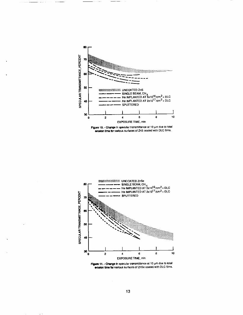
The ZnS and ZnSe s u b s t r a t e s were o n e - h a l f coa ted w i t h t h e DLC f i l m s t h a t w e r e d e t e r m i n e d t o g i v e t h e b e s t e r o s i o n p r o t e c t i o n t o fused s i l i c a and were exposed t o t h e A1203 p a r t i c l e s i n t h e m i c r o s a n d b l a s t e r ( r e f . 6 ) . 10 and 1 1 i n d i c a t e t h e change i n s p e c u l a r t r a n s m i t t a n c e a t 10 pm due t o t o t a l e r o s i o n t i m e f o r v a r i o u s s u r f a c e s o f ZnS and ZnSe, r e s p e c t i v e l y , c o a t e d w i t h t h e DLC f i l m s . I n b o t h f i g u r e s t h e r e i s an enve lope t h a t p o r t r a y s t h e e r o s i o n r a t e o f t h e uncoated s u r f a c e s . T h i s enve lope i s necessary because each ZnS and ZnSe s u b s t r a t e had a s l i g h t l y d i f f e r e n t i n i t i a l t r a n s m i t t a n c e because t h e sub- s t r a t e t h i c k n e s s was n o t t h e same, a l t h o u g h t h e e r o s i o n fol lows t h e same c u r v e . The DLC f i l m s were 0.1 pm t h i c k , and were e i t h e r s p u t t e r d e p o s i t e d from a g r a p h i t e t a r g e t or d i r e c t d e p o s i t e d from t h e s i n g l e ion-beam source w i th CH4. An i n t e r m e d i a t e l a y e r o f 0.03-pm Ge was used i n a l l cases. Some o f t h e ZnS and ZnSe s u r f a c e s were a l s o f i r s t He i o n i m p l a n t e d a t 100 keV a t doses o f 0 . 5 ~ 1 0 1 7 and 2x10¹⁷ p a r t i c l e s / c m 2 , and t h e n c o a t e d w i t h t h e DLC f i l m from t h e
F i g u r e s
6
s i n g l e beam w i t h CH4. i o n i m p l a n t a t i o n p l u s t h e DLC f i l m a f f o r d e d t h e ZnS and ZnSe s u r f a c e s any e x t e n s i o n i n p a r t i c l e e r o s i o n l i f e t i m e a f t e r exposure t o t h e A1203 p a r t i c l e s .
R a i n e r o s i o n . - Only ZnS s u r f a c e s were e v a l u a t e d for r a i n e r o s i o n p e r f o r m - ance i n t h e f a c i l i t y a t W r i g h t P a t t e r s o n A i r Force Base. The ZnS s u r f a c e s were first p o l i s h e d t o a 20/10 f i n i s h , b u t many smal l p i t s remained i n t h e s u r f a c e wh ich c o u l d n o t be removed b y p o l i s h i n g . T h i s was u n d e s i r a b l e s i n c e these p i t s c o u l d be a source o f c r a c k p r o p a g a t i o n d u r i n g t h e r a i n e r o s i o n t e s t i n g . Z i n c s u l f i d e , DLC coated ZnS, and ZnS t h a t was f i rs t i m p l a n t e d w i t h 100-keV He ions a t a dose t o 2x10¹⁷ p a r t i c l e s / c m 2 and t h e n coated w i t h t h e DLC f i l m were sub- j e c t e d t o r a i n e r o s i o n . i t was c l e a r from o p t i c a l l y v i e w i n g t h e ZnS s u r f a c e s exposed t o t h e water drop- l e t s a t 400 mph t h a t t h e r e was a per formance improvement i n t h e ZnS s u r f a c e t h a t was i o n i m p l a n t e d , c o a t e d w i t h a 0.04-pm i n t e r m e d i a t e l a y e r of Ge, and t h e n c o a t e d w i t h a O.l-pm DLC f i l m from t h e s i n g l e beam w i t h CH4. I n compar- i s o n w i t h ZnS or even ZnS windows c o a t e d w i t h a 0.1-pm-th ick DLC f i l m , t h e i o n i m p l a n t a t i o n p l u s t h e DLC c o a t i n g decreased t h e number of new p i t s and d e l a y e d t h e s t a r t o f subsur face r i n g f r a c t u r e s . T h i s c o u l d be expec ted s i n c e t h e i o n i m p l a n t a t i o n improved t h e p h y s i c a l hardness ( f i g . 4) a t t h e s u r f a c e t o a depth o f -1.0 pm o f t h e ZnS ( r e f . 9). t r a n s m i t t a n c e between 2 . 5 and 25 pm for t h e i o n - i m p l a n t e d and DLC-coated ZnS s u r f a c e a f t e r i t was exposed to r a i n e r o s i o n .
As b o t h f i g u r e s i n d i c a t e , n e i t h e r t h e DLC f i l m s n o r t h e
A l t h o u g h no q u a n t i t a t i v e d a t a w i l l be p r e s e n t e d h e r e i n ,
There a l s o w e r e no changes i n t h e s p e c u l a r
S i n c e i o n i m p l a n t a t i o n o f t h e ZnS window r e s u l t e d in improved per fo rmance, a ZnS s u r f a c e was i m p l a n t e d w i t h He+ a t 1 MeV t o f u r t h e r i n c r e a s e t h e d e p t h o f s u r f a c e p h y s i c a l hardness. However, d u r i n g t h e r a i n e r o s i o n t e s t o f t h i s ZnS s u r f a c e ( w h i c h was a l s o c o a t e d w i t h 0.1-pm DLC and 0.04-pm G e l , t h e i o n - i m p l a n t e d s u r f a c e l a y e r d e l a m i n a t e d from t h e ZnS s u b s t r a t e .
CONCLUSIONS
Three d i f f e r e n t i o n beam methods were used t o d e p o s i t d i a m o n d l i k e carbon (DLC) f i l m s on v a r i o u s s u b s t r a t e s . i t e d DLC f i l m s was n e a r l y one, w h i l e t h e i o n beam s p u t t e r - d e p o s i t e d f i l m s had a r e l a t i v e l y low H I C ra t io even w i t h t h e a d d i t i o n o f hydrogen gas. The com- p r e s s i v e s t r e s s e x h i b i t e d b y t h e DLC f i l m s d i d n o t depend on t h e hydrogen con- t e n t , b u t on o t h e r parameters such as t h e d e p o s i t i o n t e c h n i q u e and c o n d i t i o n s , and hydrocarbon gas. E l e v a t e d s t r e s s l e v e l s o f DLC f i l m s t h a t were i o n beam d e p o s i t e d w i t h C4H10 or ion beam s p u t t e r d e p o s i t e d from a g r a p h i t e t a r g e t i n d i c a t e d t h a t t h i c k f i l m s w i t h good adherence on ZnS and ZnSe c o u l d n o t be genera ted .
The hydrogen c o n t e n t o f t h e i o n beam depos-
however c o a t i n g i t e d an
Even though t h e DLC f i l m s on f u s e d s i l i c a e x h i b i t e d adherence as good as t h e maximum measurable adherence of t h e t e s t e r , these f i l m s w e r e n o t as adher- e n t on t h e ZnS and ZnSe s u b s t r a t e s , There fore , f o u r techn iques w e r e used p r i o r to t h e d e p o s i t i o n o f the DLC f i l m s t o improve t h e adherence. I o n beam c l e a n i n g and i o n i m D l a n t a t i o n d i d not i n c r e a s e f i l m adherence. I o n i m o l a n t a t i o n d i d ,
e e x h i b- a t e and
, improve t h e p h y s i c a l hardness o f t h e s u b s t r a t e s . An i n t e r m e d i a o f Ge s u c c e s s f u l l y a l l o w e d t h e DLC f i l m s t o remain adherent , and adherence equal to t h e s t r e h g t h o f t h e s u b s t r a t e . Th is i n t e r m e d
Ge f i l m caused a s m a l l r e d u c t i o n i n t h e I R s p e c u l a r t r a n s m i t t a n c e o f ZnS ZnSe a t s h o r t e r wavelengths, b u t o n l y a 1 p e r c e n t loss o c c u r r e d a t 10 pm
7
S i n c e t h e DLC f i l m s d e p o s i t e d on S i a c t e d as an a n t i r e f l e c t i v e c o a t i n g , t h e r e b y enhancing t h e I R t r a n s m i t t a n c e , t h i s r e d u c t i o n c o u l d be e l i m i n a t e d b y p i c k i n g t h e p r o p e r c o m b i n a t i o n of DLC and Ge t h i c k n e s s e s t o produce an a n t i r e f l e c t i v e c o a t i n g .
A l though i o n i m p l a n t a t i o n p l u s a DLC f i l m d i d n o t p r o t e c t t h e ZnS and ZnSe windows exposed t o t h e s i m u l a t e d p a r t i c l e e r o s i o n , i t d i d improve t h e per fo rm- ance o f ZnS exposed t o r a i n e r o s i o n . The ZnS windows t h a t were He i o n i m p l a n t e d and coated w i t h DLC and an i n t e r m e d i a t e Ge l a y e r had fewer new s u r f a c e p i t s and a d e l a y e d s t a r t o f s u b s u r f a c e r i n g c r a c k s . Harden ing t h e window s u r f a c e i t s e l f by i o n i m p l a n t a t i o n , i n a d d i t i o n t o c o a t i n g i t w i t h a t h i c k s t r e s s - f r e e d i a m o n d l i k e carbon f i l m , m i g h t i n c r e a s e t h e l i f e t i m e o f i n f r a r e d t r a n s m i t t i n g windows and p r o t e c t them from b o t h r a i n and l e s s severe p a r t i c l e e r o s i o n .
REFERENCES
1 . N a d l e r , M . P . ; Donovan, T . M . ; and Green, A.K.: Thermal A n n e a l i n g Study of Carbon F i l m s Formed by t h e Plasma Decompos i t ion o f Hydrocarbons. T h i n S o l i d F i l m s , v o l . 116, no. 1-3, June 22, 1984, pp . 241-247.
2 . H o l l a n d , L . ; and Ojha , S . M . : I n f r a r e d Transparent and Amorphous Carbon Grown Under I o n Impact i n a Butane Plasma. T h i n S o l i d F i l m s , v o l . 48, no. 3, Feb . 1 , 1978, p p . L21-L23.
3. Banks, B . A . ; and R u t l e d g e , S .K . : I o n Beam S p u t t e r D e p o s i t e d Diamond-Like F i l m s . NASA TM-82873, 1982.
4 . M i r t i c h , M.J.; Swec, D . M . ; and Angus, J.C.: Dual I o n Beam D e p o s i t i o n o f Carbon F i l m s W i t h D i a m o n d l i k e P r o p e r t i e s . NASA TM-83743, 1984.
5. N i r , D . : Mechanica l P r o t e c t i o n o f DLC F i l m s on Fused S i l i c a S l i d e s . NASA TM-87056, 1985.
6 . Swec, D.M.; M i r t i c h , M.J.; N i r , D. ; and Banks, B . A . : Comparison o f P r o t e c t i v e C o a t i n g s f o r I n f r a r e d T r a n s m i t t i n g Windows. J . Vac. S c i . Techno l . A , v o l . 4, no. 6 , Nov.-Dec. 1986, pp. 3030-3031.
7 . Angus, J .C. ; S t u i t z , J .E. ; S h i l l e r , P .J . ; McDonald, J.R.; M i r t i c h , M.J.; and Domi tz , S . : Compos i t ion and P r o p e r t i e s o f t h e S o - c a l l e d "Diamond- L i k e " Amorphous Carbon F i l m s . T h i n S o l i d F i l m s , v o l . 118, no. 3, Aug. 1 7 , 1984, pp. 311-320.
8 . M i r t i c h , M . J . : Adherence o f I o n Beam S p u t t e r D e p o s i t e d Meta l F i l m s on H-13 S t e e l . J . Vac. S c i . Techno l . , v o l . 18, no. 2 , Mar. 1981, pp. 186-189.
9 . M i r t i c h , M.J. ; Nir, D . ; S w e c , D .M. ; and Banks, B . A . : The Use of- I n t e r - med ia te Layers to Improve t h e Adherence of D i a m o n d l i k e Carbon F i l m s on ZnS and ZnSe. J . Vac. S c i . Techno l . A , v o l . 4, 1986, pp. 2680-2681.
10. Bowman, R.L.; M i r t i c h , M.J. ; and Weigand, A.J. : The Changes i n O p t i c a l P r o p e r t i e s o f V a r i o u s T r a n s m i t t i n g M a t e r i a l s Due t o S i m u l a t e d M i c r o - m e t e o r o i d Exposure. NASA TM X-52687, 1969.
8
1 1 . Angus, J.C.; M i r t i ch , M . J . ; and Wintucky, E . G . : Ion Beam Deposition o f Amorphous Carbon F i l m s Wlth Diamond Like Propert ies. Formation by Ion Implantat ion, S.T . P i c r a u x and W.J. Choyke, e d s . , North-Holland, 1982, pp. 433-440.
M e t a s t a b l e M a t e r i a l s
Deposition method
Single beam, CH4
Dual beam, CH4 Single beam, C4H10
Graphite sputter ing Graphite sputter ing
12 . M i r t i c h , M.J.; N i r , D . ; Swec, D.M.; and Banks, B . A . : Diamondlike Carbon Protect ive Coatings for I R Mater ia ls . NASA TM-87083, 1985.
Stress, dyne/crn2
0.9x10'0 2.6 .9
1 .6 2.3
TABLE I . - PROPERTIES OF DIAMONDLIKE CARBON F I L M S DEPOSITED BY DIFFERENT I O N BEAM
DEPOSITION METHODS
Hydrogen content, H/C
0.91 .62 . 62
.22
.53
I + H2 addit ion I I I
9
N . 6 g 2 -
vi
a v) W
Li W
v) W
5
8‘-
O- 0
3 x 9
r,
0 80 100 120 140 160
WAr, PERCENT
Figure 1. - Compressive stress as function of WAr gas ratio for 0.l-pmthick DLC films made with CH4 and C4H10 in the single ion- beam Swrm at 110 eV.
3x1O1O r N
6 t 6 9 L i 2
W a L 35 PERCENT Hg -.
27 PERCENT H 2 7 , 8.
31 PERCENTH2-
I -‘-la PERCENT H2
10
2(
16
N . € c a.. u
12 vi
a
2 m a
a
cn W
2 W
u) W
0 : 4
0
09
50 100 150 200 250 DEPOSITION ENERGY, eV
Figure 2. - Compressive stress as function of depositlon energy for , 0.l-pn-thick DLC films made with CH4 in the single ion-beam source.
0 10 20 30 40 50
LOAD, g
Figure 4. - Vickers hardness as function of applied load for unimpianted ZnS, and for ZnS implanted with He ions, at 100 keV at a dose of 2x10¹⁷ partides’cm2.
IMPLANTED /
DEPOSITION THICKNESS, METHOD )un
0 SPWERED 0.17 0 DUALBEAM.
.I5
A SINGLE BEAM, (344
P CH4 . I5
0 .4 .8 .8 1 .o 1.2 1.4
WAVELENGTH, pm Flgure 5. - Transmittance as function of wavelength for
M C fllme made with CH4 in the single or dual lon- barn source, and DLC films made by sputter deposltkm of a Oraphlte taroel.
1 i I I WAVELENGTH, pm
Figure 6. - Specular bMwm dZn8 befom and after He ion implantation at 100 keV at a dose of 5x1Ol6 particles/cm2.
11
r UNCOATED ZnSe
c
WAVELENGTH, pn
Figure 7. - Specular transmiltance of 0 . 1 - p DLC film made with CH4 in the single beam with and without an intermediate layer of 0.03-pm Ge on the ZnSe substrate.
I
I
1 .a
0
1 .a
0 0.2-)lm-THICK DLC FILM 0 0.1-V-THICK DLC FILM - UNCOATED FUSED SILICA -/
/ I I I I I .2 .4 .6 .8 1 .a
NORMALIZED SPECULAR TRANSMRTANCE, UNCOATED FUSED SILICA
Figure 8. - Normalized specular transmlltance of fused silica coated with DLC films, 0.1 and 0.2 pm thick, made with CH4 In the single Ion-beam source, and uncoated fused silica, both after exposure to 1 0 0 - p Si02 particles at 27 mlsec.
8 .8 P
0
0 SPLITTERED
0 DUAL BEAM, CH4
A SINGLE BEAM, CH4
n SPUTTERED+H~
- UNCOATED FUSED SILICA
.2 .4 .6 .8
NORMALIZED SPECULAR TRANSMRTANCE OF UNCOATED FUSED SILICA
n
Figure 9. - Protection that 0.1-p-thick DLC films deposited by various methods afforded fused silica after exposure to 100-pn Si02 particles at 27 mlsec.
12
...I-- ------_---- 5 5 --- ----
pm >:.x i.... I ,..... . ~ . x . ~ : . ~ ~ . : . : ~ . ~ ~ ~ ~ : . : : ~ ~ : UNWATE D Zn S - - - SINGLE BEAM, CH ------ He I M P L A N T E D A T ~ x ~ O ~ ~ / C ~ ~ + DLC --- He IMPLANTEDAT 2x1d7/cm2+ DLC
I-
h ---- SPUTTERED v)
I I I I 1 30- 0 2 4 6 a 10
EXPOSURE TIME, min
Figure IO. -Change In specular transmitlance at 10 pm due to total eroskn time for various surfaces of ZnS coated with DLC films.
UNCOATED ZnSe
------ He lMPLANTEDAT5x1016/cm2+ DLC --- He I M P L A N T E D A T ~ x ~ O ~ ~ / C ~ ~ + DLC
80
- - - - SPUlTERED !z E 3 7 0
&o E
3
w
f a I-
0 4 0 w B
0 2 4 6 a 10 30
EXPOSURE TIME. min
Flguo 11. - Change In specular transmittanm at 10 pn due to total emslon tkne fw various surfaces of ZnSe coated with DLC films.
13
1. Report No. 2. Government Accession No.
NASA TM- 102 1 1 1
4. Title and Subtitle
Diamondlike Carbon Protective Coatings for Optical Windows
7. Author(s)
Diane M. Swec and Michael J. Mirtich
9. Performing Organization Name and Address
National Aeronautics and Space Administration Lewis Research Center Cleveland, Ohio 44135-3191
3. Recipient's Catalog No.
5. Report Date
6. Performing Organization Code
8. Performing Organization Report No.
E-488 1
10. Work Unit No.
506-4 1-4 1
12. Sponsoring Agency Name and Address
13. Type of Report and Period Covered
Technical Memorandum
17. Key Words (Suggested by Author(s))
Diamondlike carbon films Ion beam deposition Infrared transmitting windows
National Aeronautics and Space Administration Washington, D.C. 20546-0001
18. Distribution Statement
Unclassified - Unlimited Subject Category 74
14. Sponsoring Agency Code r------
19. Security Classif. (of this report) 20. Security Classif. (of this page) 21. No of pages
Unclassified Unclassified 14
15. Supplementary Notes
Prepared for the 1989 Technical Symposia on Aerospace Sensing sponsored by The International Society for Optical Engineering, Orlando, Florida, March 27-31, 1989.
22. Price'
A03
16. Abstract
Diamondlike carbon (DLC) films were deposited on infrared transmitting optical windows and were evaluated as protective coatings for these windows exposed to particle and rain erosion. The DLC films were deposited on zinc selenide (ZnSe) and zinc sulfide (ZnS) by three different ion beam methods: (1) sputter deposition from a carbon target using an 8-cm argon ion source, (2) direct deposition by a 30-cm hollow cathode ion source with hydrocarbon gas in argon, and (3) dual beam direct deposition by the 30-cm hollow cathode ion source and an 8-cm argon ion source. In an attempt to improve the adherence of the DLC films on ZnSe and ZnS, ion beam cleaning, ion implantation with helium and neon ions, or sputter deposition of a thin, ion beam intermediate coating was employed prior to deposition of the DLC film. The protection that the DLC films afforded the windows from particle and rain erosion was evaluated, along with the hydrogen content, adherence, intrinsic stress, and infrared transmittance of the films. Because of the elevated stress levels in the ion beam sputtered DLC films and in those ion beam deposited with butane, films thicker than 0.1 pm and with good adherence on ZnS and ZnSe could not be generated. An intermediate coating of germanium successfully allowed the DLC films to remain adherent to the optical windows and caused only negligible reduction in the specular transmittance of the ZnS and ZnSe at 10 pm. These DLC films did not protect the optical windows from simulated particle erosion; however, they did improve the performance of ZnS exposed to rain erosion.
*For sale by the National Technical Information Service, Springfield, Virginia 22161 NASA FORM 1626 OCT 86