Embed Size (px)
Citation preview
www.MillerWelds.com
Processes
Description
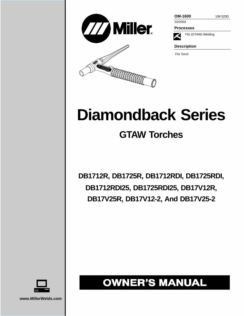
TIG Torch
OM-1600 199 525D
10/2004
DB1712RDI25, DB1725RDI25, DB17V12R,
Diamondback SeriesGTAW Torches
TIG (GTAW) Welding
DB1712R, DB1725R, DB1712RDI, DB1725RDI,
DB17V25R, DB17V12-2, And DB17V25-2
Miller Electric manufactures a full lineof welders and welding related equipment.For information on other quality Millerproducts, contact your local Miller distributor to receive the latest fullline catalog or individual catalog sheets. To locate your nearestdistributor or service agency call 1-800-4-A-Miller, or visit us atwww.MillerWelds.com on the web.
Thank you and congratulations on choosing Miller. Now you can getthe job done and get it done right. We know you don’t have time to doit any other way.
That’s why when Niels Miller first started building arc welders in 1929,he made sure his products offered long-lasting value and superiorquality. Like you, his customers couldn’t afford anything less. Millerproducts had to be more than the best they could be. They had to be thebest you could buy.
Today, the people that build and sell Miller products continue thetradition. They’re just as committed to providing equipment and servicethat meets the high standards of quality and value established in 1929.
This Owner’s Manual is designed to help you get the most out of yourMiller products. Please take time to read the Safety precautions. Theywill help you protect yourself against potential hazards on the worksite.
We’ve made installation and operation quickand easy. With Miller you can count on yearsof reliable service with proper maintenance.And if for some reason the unit needs repair,there’s a Troubleshooting section that willhelp you figure out what the problem is. Theparts list will then help you to decide theexact part you may need to fix the problem.Warranty and service information for yourparticular model are also provided.
Miller is the first weldingequipment manufacturer inthe U.S.A. to be registered tothe ISO 9001:2000 QualitySystem Standard.
Working as hard as you do− every power source fromMiller is backed by the mosthassle-free warranty in thebusiness.
From Miller to You
Mil_Thank 7/03

TABLE OF CONTENTS
SECTION 1 −SAFETY PRECAUTIONS FOR GTAW TORCHES − READ BEFORE USING 1 . . . . . . . . . . . . . . 1-1. Symbol Usage 1 . . . . . . . . . . . . . . . . . . . . . . . . . . . . . . . . . . . . . . . . . . . . . . . . . . . . . . . . . . . . . . . . . . . . . . . . 1-2. GTAW Torch Hazards 1 . . . . . . . . . . . . . . . . . . . . . . . . . . . . . . . . . . . . . . . . . . . . . . . . . . . . . . . . . . . . . . . . .
EMF INFORMATION 2 . . . . . . . . . . . . . . . . . . . . . . . . . . . . . . . . . . . . . . . . . . . . . . . . . . . . . . . . . . . . . . . . . . . . . . . . . . SECTION 2 − SPECIFICATIONS 3 . . . . . . . . . . . . . . . . . . . . . . . . . . . . . . . . . . . . . . . . . . . . . . . . . . . . . . . . . . . . . . . .
2-1. Specifications 3 . . . . . . . . . . . . . . . . . . . . . . . . . . . . . . . . . . . . . . . . . . . . . . . . . . . . . . . . . . . . . . . . . . . . . . . . 2-2. Duty Cycle 3 . . . . . . . . . . . . . . . . . . . . . . . . . . . . . . . . . . . . . . . . . . . . . . . . . . . . . . . . . . . . . . . . . . . . . . . . . . .
SECTION 3 − INSTALLATION 4 . . . . . . . . . . . . . . . . . . . . . . . . . . . . . . . . . . . . . . . . . . . . . . . . . . . . . . . . . . . . . . . . . . 3-1. Required Torch Parts And Torch Assembly 4 . . . . . . . . . . . . . . . . . . . . . . . . . . . . . . . . . . . . . . . . . . . . . . . . 3-2. International Style Connector Assembly 4 . . . . . . . . . . . . . . . . . . . . . . . . . . . . . . . . . . . . . . . . . . . . . . . . . .
3-3. Connecting Torch 5 . . . . . . . . . . . . . . . . . . . . . . . . . . . . . . . . . . . . . . . . . . . . . . . . . . . . . . . . . . . . . . . . . . . . . SECTION 4 − MAINTENANCE & TROUBLESHOOTING 7 . . . . . . . . . . . . . . . . . . . . . . . . . . . . . . . . . . . . . . . . . . .
4-1. Routine Maintenance 7 . . . . . . . . . . . . . . . . . . . . . . . . . . . . . . . . . . . . . . . . . . . . . . . . . . . . . . . . . . . . . . . . . . 4-2. Troubleshooting 7 . . . . . . . . . . . . . . . . . . . . . . . . . . . . . . . . . . . . . . . . . . . . . . . . . . . . . . . . . . . . . . . . . . . . . .
SECTION 5 − SELECTING AND PREPARING TUNGSTEN ELECTRODE FOR DC OR AC WELDING 9 . . . . 5-1. Selecting Tungsten Electrode (Wear Clean gloves To Prevent Contamination Of Tungsten) 9 . . . . . . . . 5-2. Preparing Tungsten Electrode For Welding 10 . . . . . . . . . . . . . . . . . . . . . . . . . . . . . . . . . . . . . . . . . . . . . . . .
SECTION 6 − GUIDELINES FOR TIG WELDING (GTAW) 10 . . . . . . . . . . . . . . . . . . . . . . . . . . . . . . . . . . . . . . . . . . 6-1. Positioning The Torch 10 . . . . . . . . . . . . . . . . . . . . . . . . . . . . . . . . . . . . . . . . . . . . . . . . . . . . . . . . . . . . . . . . . .
6-2. Torch Movement During Welding 11 . . . . . . . . . . . . . . . . . . . . . . . . . . . . . . . . . . . . . . . . . . . . . . . . . . . . . . . . 6-3. Positioning Torch Tungsten For Various Weld Joints 11 . . . . . . . . . . . . . . . . . . . . . . . . . . . . . . . . . . . . . . . .
SECTION 7 − PARTS LIST 12 . . . . . . . . . . . . . . . . . . . . . . . . . . . . . . . . . . . . . . . . . . . . . . . . . . . . . . . . . . . . . . . . . . . . . WARRANTY

Notes
OM-1600 Page 1
SECTION 1 −SAFETY PRECAUTIONS FOR GTAWTORCHES − READ BEFORE USING
SR6_8/03
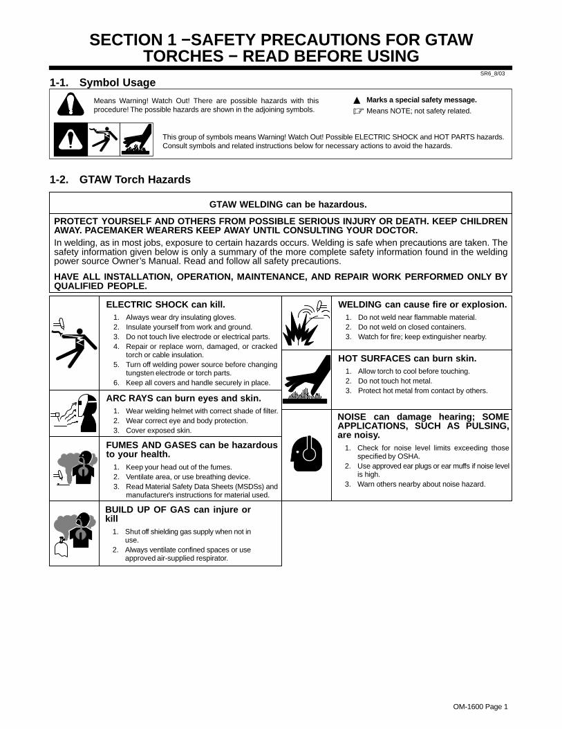
1-1. Symbol Usage
Means Warning! Watch Out! There are possible hazards with thisprocedure! The possible hazards are shown in the adjoining symbols.
This group of symbols means Warning! Watch Out! Possible ELECTRIC SHOCK and HOT PARTS hazards.Consult symbols and related instructions below for necessary actions to avoid the hazards.
� Marks a special safety message.
� Means NOTE; not safety related.
1-2. GTAW Torch Hazards
PROTECT YOURSELF AND OTHERS FROM POSSIBLE SERIOUS INJURY OR DEATH. KEEP CHILDRENAWAY. PACEMAKER WEARERS KEEP AWAY UNTIL CONSULTING YOUR DOCTOR.In welding, as in most jobs, exposure to certain hazards occurs. Welding is safe when precautions are taken. Thesafety information given below is only a summary of the more complete safety information found in the weldingpower source Owner’s Manual. Read and follow all safety precautions.
HAVE ALL INSTALLATION, OPERATION, MAINTENANCE, AND REPAIR WORK PERFORMED ONLY BYQUALIFIED PEOPLE.
GTAW WELDING can be hazardous.
ARC RAYS can burn eyes and skin.1. Wear welding helmet with correct shade of filter.2. Wear correct eye and body protection.3. Cover exposed skin.
ELECTRIC SHOCK can kill.1. Always wear dry insulating gloves.2. Insulate yourself from work and ground.3. Do not touch live electrode or electrical parts.4. Repair or replace worn, damaged, or cracked
torch or cable insulation.5. Turn off welding power source before changing
tungsten electrode or torch parts.6. Keep all covers and handle securely in place.
WELDING can cause fire or explosion.1. Do not weld near flammable material.2. Do not weld on closed containers.3. Watch for fire; keep extinguisher nearby.
NOISE can damage hearing; SOMEAPPLICATIONS, SUCH AS PULSING,are noisy.
1. Check for noise level limits exceeding thosespecified by OSHA.
2. Use approved ear plugs or ear muffs if noise levelis high.
3. Warn others nearby about noise hazard.
HOT SURFACES can burn skin.1. Allow torch to cool before touching.2. Do not touch hot metal.3. Protect hot metal from contact by others.
FUMES AND GASES can be hazardousto your health.
1. Keep your head out of the fumes.2. Ventilate area, or use breathing device.3. Read Material Safety Data Sheets (MSDSs) and
manufacturer’s instructions for material used.
BUILD UP OF GAS can injure orkill
1. Shut off shielding gas supply when not inuse.
2. Always ventilate confined spaces or useapproved air-supplied respirator.

OM-1600 Page 2
EMF INFORMATIONConsiderations About Welding And The Effects Of Low FrequencyElectric And Magnetic FieldsWelding current, as it flows through welding cables, will cause electro-magnetic fields. There has been and still is some concern about suchfields. However, after examining more than 500 studies spanning 17years of research, a special blue ribbon committee of the NationalResearch Council concluded that: “The body of evidence, in thecommittee’s judgment, has not demonstrated that exposure to power-frequency electric and magnetic fields is a human-health hazard.”However, studies are still going forth and evidence continues to beexamined. Until the final conclusions of the research are reached, youmay wish to minimize your exposure to electromagnetic fields whenwelding or cutting.To reduce magnetic fields in the workplace, use the followingprocedures:
1. Keep cables close together by twisting or taping them.
2. Arrange cables to one side and away from the operator.
3. Do not coil or drape cables around your body.
4. Keep welding power source and cables as far away from oper-ator as practical.
5. Connect work clamp to workpiece as close to the weld aspossible.
About Pacemakers:Pacemaker wearers consult your doctor first. If cleared by your doc-tor, then following the above procedures is recommended.
OM-1600 Page 3
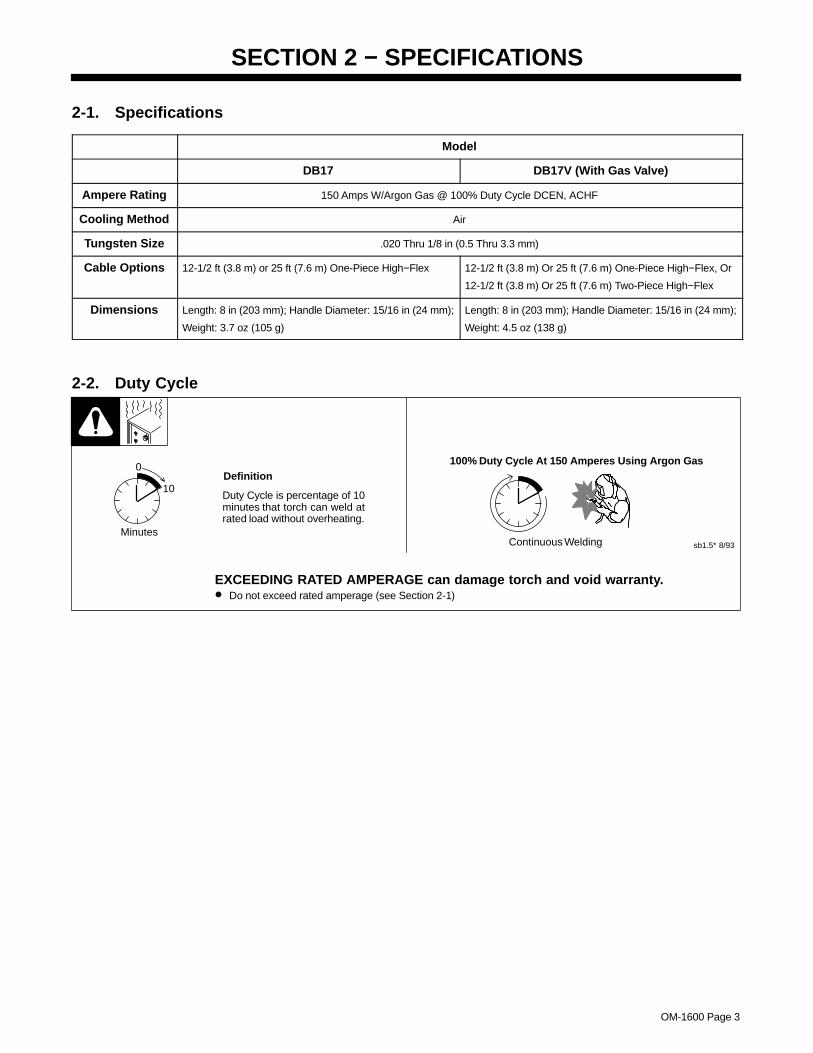
SECTION 2 − SPECIFICATIONS
2-1. Specifications
Model
DB17 DB17V (With Gas Valve)
Ampere Rating 150 Amps W/Argon Gas @ 100% Duty Cycle DCEN, ACHF
Cooling Method Air
Tungsten Size .020 Thru 1/8 in (0.5 Thru 3.3 mm)
Cable Options 12-1/2 ft (3.8 m) or 25 ft (7.6 m) One-Piece High−Flex 12-1/2 ft (3.8 m) Or 25 ft (7.6 m) One-Piece High−Flex, Or
12-1/2 ft (3.8 m) Or 25 ft (7.6 m) Two-Piece High−Flex
Dimensions Length: 8 in (203 mm); Handle Diameter: 15/16 in (24 mm);
Weight: 3.7 oz (105 g)
Length: 8 in (203 mm); Handle Diameter: 15/16 in (24 mm);
Weight: 4.5 oz (138 g)
2-2. Duty Cycle
Continuous Welding sb1.5* 8/93
100% Duty Cycle At 150 Amperes Using Argon Gas
Duty Cycle is percentage of 10minutes that torch can weld atrated load without overheating.
0
10
Minutes
Definition
EXCEEDING RATED AMPERAGE can damage torch and void warranty.• Do not exceed rated amperage (see Section 2-1)
OM-1600 Page 4
SECTION 3 − INSTALLATION
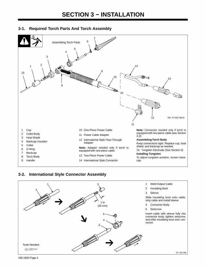
3-1. Required Torch Parts And Torch Assembly
Ref. ST-802 566-B
1 Cup2 Collet Body3 Heat Shield4 Backcap Insulator5 Collet6 O-Ring7 Backcap8 Torch Body9 Handle
10 One-Piece Power Cable
11 Power Cable Adapter
12 International Style Flow-ThroughAdapter
Note: Adapter needed only if torch isequipped with one-piece cable.
13 Two-Piece Power Cable
14 International Style Connector
Note: Connector needed only if torch isequipped with two-piece cable (see Section3-2).Assembling T orch BodyKeep connections tight. Replace cup, heatshield, and backcap as needed.15 Tungsten Electrode (See Section 5)Installing T ungstenTo adjust tungsten position, loosen back-cap.
Assembling Torch Parts
1 2
3
4
11
12
5
7
9
6
15
Or
14
8
10
13
3-2. International Style Connector Assembly
1 Weld Output Cable
2 Insulating Boot
3 Sleeve
Slide insulating boot onto cable;strip cable and install sleeve.
4 Connector Body
5 Setscrew
Insert cable with sleeve fully intoconnector body, tighten setscrew,and slide insulating boot over con-nector.
ST-156 496
Tools Needed:
1
2
3
1 in(26 mm)
3
4
5
OM-1600 Page 5
3-3. Connecting Torch
A. Connecting Torch With One-Piece Cable
Turn Off welding power source, anddisconnect input power before in-stalling torch.Obtain the following hose:
1 Gas Hose With 5/8-18 Right-Hand Fittings
Connections:
2 Regulator/Flowmeter
3 Gas Cylinder
4 Welding Power Source
5 Gas Valve
Operating Torch Gas Valve:
Valve controls gas preflow and post-flow. Open valve on torch just beforewelding.
Preflow is used to purge the immedi-ate weld area of atomsphere.
Postflow is required to cool tungstenand weld, and to prevent contamina-tion of tungsten and weld. After weld-ing, leave valve open about 1 sec-ond for every 10 amperes of weldcurrent. Close valve on torch whenpostflow is finished.
6 One-Piece Torch Cable
7 Power Cable Adapter
Connect gas hose and power cableto adapter before connecting adapt-er to weld output terminal.
8 Work Clamp
Connect work clamp to clean, paint-free location on workpiece, close toweld.
Use wire brush to clean weld jointarea.
9 Foot Control
803 313
If applicable, install high-frequency unit.
Tools Needed:
5/8, 7/8 in
1
2
3
5
Torch Without Gas Valve
4
8 7
6
1
2
3
4
5
6
78
Torch With Gas Valve
9
9
OM-1600 Page 6
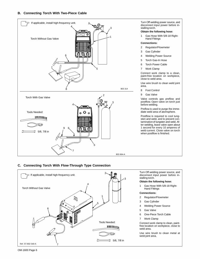
B. Connecting Torch With Two-Piece Cable
803 664-A
Turn Off welding power source, anddisconnect input power before in-stalling torch.Obtain the following hose:
1 Gas Hose With 5/8-18 Right-Hand Fittings
Connections:
2 Regulator/Flowmeter
3 Gas Cylinder
4 Welding Power Source
5 Torch Gas-In Hose
6 Torch Power Cable
7 Work Clamp
Connect work clamp to a clean,paint-free location on workpiece,close to weld area.
Use wire brush to clean weld jointarea.
8 Foot Control
9 Gas Valve
Valve controls gas preflow andpostflow. Open valve on torch justbefore welding.
Preflow is used to purge the imme-diate weld area of atomsphere.
Postflow is required to cool tung-sten and weld, and to prevent con-tamination of tungsten and weld. Af-ter welding, leave valve open about1 second for every 10 amperes ofweld current. Close valve on torchwhen postflow is finished.
If applicable, install high-frequency unit.
Tools Needed:
5/8, 7/8 in
Torch With Gas Valve
9
5
6
7
4
2
3
Torch Without Gas Valve
42
3
1
6
7
8
5
803 314
−
C. Connecting Torch With Flow-Through Type Connection
Turn Off welding power source, anddisconnect input power before in-stalling torch.Obtain the following hose:
1 Gas Hose With 5/8-18 Right-Hand Fittings
Connections:
2 Regulator/Flowmeter
3 Gas Cylinder
4 Welding Power Source
5 Gas Valve
6 One-Piece Torch Cable
7 Work Clamp
Connect work clamp to clean, paint-free location on workpiece, close toweld area.
Use wire brush to clean metal atweld joint area.
Ref. ST-802 540-A
If applicable, install high-frequency unit.
Tools Needed:
5/8, 7/8 in
1
2
3
4
5
6
7
Torch Without Gas Valve
OM-1600 Page 7
SECTION 4 − MAINTENANCE & TROUBLESHOOTING
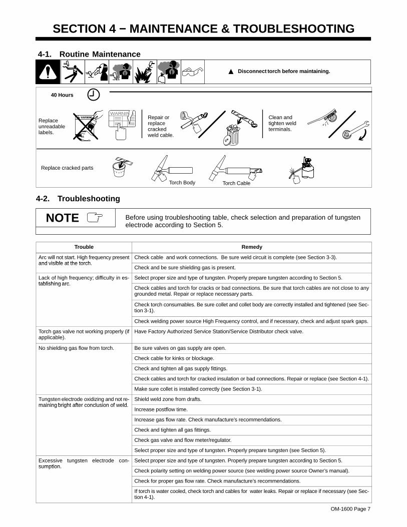
4-1. Routine Maintenance
� Disconnect torch before maintaining.
40 Hours
Replaceunreadablelabels.
Repair orreplacecrackedweld cable.
Clean andtighten weldterminals.
Replace cracked parts
Torch Body Torch Cable
4-2. Troubleshooting
Before using troubleshooting table, check selection and preparation of tungstenelectrode according to Section 5.
NOTE
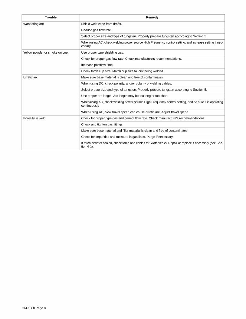
Trouble Remedy
Arc will not start. High frequency presentand visible at the torch.
Check cable and work connections. Be sure weld circuit is complete (see Section 3-3).and visible at the torch.
Check and be sure shielding gas is present.
Lack of high frequency; difficulty in es-tablishing arc.
Select proper size and type of tungsten. Properly prepare tungsten according to Section 5.tablishing arc.
Check cables and torch for cracks or bad connections. Be sure that torch cables are not close to anygrounded metal. Repair or replace necessary parts.
Check torch consumables. Be sure collet and collet body are correctly installed and tightened (see Sec-tion 3-1).
Check welding power source High Frequency control, and if necessary, check and adjust spark gaps.
Torch gas valve not working properly (ifapplicable).
Have Factory Authorized Service Station/Service Distributor check valve.
No shielding gas flow from torch. Be sure valves on gas supply are open.
Check cable for kinks or blockage.
Check and tighten all gas supply fittings.
Check cables and torch for cracked insulation or bad connections. Repair or replace (see Section 4-1).
Make sure collet is installed correctly (see Section 3-1).
Tungsten electrode oxidizing and not re-maining bright after conclusion of weld.
Shield weld zone from drafts.maining bright after conclusion of weld.
Increase postflow time.
Increase gas flow rate. Check manufacture’s recommendations.
Check and tighten all gas fittings.
Check gas valve and flow meter/regulator.
Select proper size and type of tungsten. Properly prepare tungsten (see Section 5).
Excessive tungsten electrode con-sumption.
Select proper size and type of tungsten. Properly prepare tungsten according to Section 5.sumption.
Check polarity setting on welding power source (see welding power source Owner’s manual).
Check for proper gas flow rate. Check manufacture’s recommendations.
If torch is water cooled, check torch and cables for water leaks. Repair or replace if necessary (see Sec-tion 4-1).
OM-1600 Page 8
Trouble Remedy
Wandering arc Shield weld zone from drafts.
Reduce gas flow rate.
Select proper size and type of tungsten. Properly prepare tungsten according to Section 5.
When using AC, check welding power source High Frequency control setting, and increase setting if nec-essary.
Yellow powder or smoke on cup. Use proper type shielding gas.
Check for proper gas flow rate. Check manufacture’s recommendations.
Increase postflow time.
Check torch cup size. Match cup size to joint being welded.
Erratic arc Make sure base material is clean and free of contaminates.
When using DC, check polarity, and/or polarity of welding cables.
Select proper size and type of tungsten. Properly prepare tungsten according to Section 5.
Use proper arc length. Arc length may be too long or too short.
When using AC, check welding power source High Frequency control setting, and be sure it is operatingcontinuously.
When using AC, slow travel speed can cause erratic arc. Adjust travel speed.
Porosity in weld. Check for proper type gas and correct flow rate. Check manufacture’s recommendations.
Check and tighten gas fittings.
Make sure base material and filler material is clean and free of contaminates.
Check for impurities and moisture in gas lines. Purge if necessary.
If torch is water cooled, check torch and cables for water leaks. Repair or replace if necessary (see Sec-tion 4-1).
OM-1600 Page 9
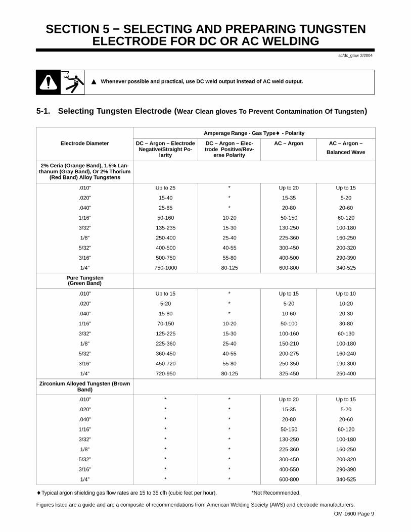
SECTION 5 − SELECTING AND PREPARING TUNGSTENELECTRODE FOR DC OR AC WELDING
ac/dc_gtaw 2/2004
� Whenever possible and practical, use DC weld output instead of AC weld output.
5-1. Selecting Tungsten Electrode ( Wear Clean gloves To Prevent Contamination Of Tungsten )
Amperage Range - Gas Type♦ - Polarity
Electrode Diameter DC − Argon − ElectrodeNegative/Straight Po-
larity
DC − Argon − Elec-trode Positive/Rev-
erse Polarity
AC − Argon AC − Argon −
Balanced Wave
2% Ceria (Orange Band), 1.5% Lan-thanum (Gray Band), Or 2% Thorium
(Red Band) Alloy Tungstens
.010” Up to 25 * Up to 20 Up to 15
.020” 15-40 * 15-35 5-20
.040” 25-85 * 20-80 20-60
1/16” 50-160 10-20 50-150 60-120
3/32” 135-235 15-30 130-250 100-180
1/8” 250-400 25-40 225-360 160-250
5/32” 400-500 40-55 300-450 200-320
3/16” 500-750 55-80 400-500 290-390
1/4” 750-1000 80-125 600-800 340-525
Pure Tungsten(Green Band)
.010” Up to 15 * Up to 15 Up to 10
.020” 5-20 * 5-20 10-20
.040” 15-80 * 10-60 20-30
1/16” 70-150 10-20 50-100 30-80
3/32” 125-225 15-30 100-160 60-130
1/8” 225-360 25-40 150-210 100-180
5/32” 360-450 40-55 200-275 160-240
3/16” 450-720 55-80 250-350 190-300
1/4” 720-950 80-125 325-450 250-400
Zirconium Alloyed Tungsten (BrownBand)
.010” * * Up to 20 Up to 15
.020” * * 15-35 5-20
.040” * * 20-80 20-60
1/16” * * 50-150 60-120
3/32” * * 130-250 100-180
1/8” * * 225-360 160-250
5/32” * * 300-450 200-320
3/16” * * 400-550 290-390
1/4” * * 600-800 340-525
♦Typical argon shielding gas flow rates are 15 to 35 cfh (cubic feet per hour). *Not Recommended.
Figures listed are a guide and are a composite of recommendations from American Welding Society (AWS) and electrode manufacturers.
OM-1600 Page 10
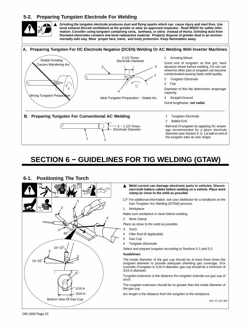
5-2. Preparing Tungsten Electrode For Welding� Grinding the tungsten electrode produces dust and flying sparks which can cause injury and start fires. Use
local exhaust (forced ventilation) at the grinde r or wear an approved respirator. Read MSDS for safety infor-mation. Consider using tungsten containing ceria, lanthana, or yttria instead of thoria. Grinding dust fromthoriated electrodes contains low-level radioactive material. Properly dispose of grinder dust in an environ-mentally safe way. Wear proper face, hand, and body protection. Keep flammables away.
A. Preparing T ungsten For DC Electrode Negative (DCEN) W elding Or AC W elding With Inverter Machines
Ideal Tungsten Preparation − Stable Arc
2-1/2 TimesElectrode Diameter
1 Grinding Wheel
Grind end of tungsten on fine grit, hardabrasive wheel before welding. Do not usewheel for other jobs or tungsten can becomecontaminated causing lower weld quality.
2 Tungsten Electrode3 Flat
Diameter of this flat determines amperagecapacity.
4 Straight Ground
Grind lengthwise, not radial .
1
3
4
1 Tungsten Electrode
2 Balled End
Ball end of tungsten by applying AC amper-age recommended for a given electrodediameter (see Section 5-1). Let ball on end ofthe tungsten take its own shape.
B. Preparing Tungsten For Conventional AC Welding
1 − 1-1/2 Times
2
Electrode Diameter
Causes Wandering Arc2
1
Wrong Tungsten Preparation
Radial Grinding
SECTION 6 − GUIDELINES FOR TIG WELDING (GTAW)
6-1. Positioning The Torch� Weld current can damage electronic parts in vehicles. Discon-
nect both battery cables before welding on a vehicle. Place workclamp as close to the weld as possible.
� For additional information, see your distributor for a handbook on theGas Tungsten Arc Welding (GTAW) process.
1 Workpiece
Make sure workpiece is clean before welding.
2 Work Clamp
Place as close to the weld as possible.
3 Torch
4 Filler Rod (If Applicable)5 Gas Cup
6 Tungsten Electrode
Select and prepare tungsten according to Sections 5-1 and 5-2.
Guidelines:
The inside diameter of the gas cup should be at least three times thetungsten diameter to provide adequate shielding gas coverage. (Forexample, if tungsten is 1/16 in diameter, gas cup should be a minimum of3/16 in diameter.
Tungsten extension is the distance the tungsten extends out gas cup oftorch.
The tungsten extension should be no greater than the inside diameter ofthe gas cup.
Arc length is the distance from the tungsten to the workpiece.
1
10−25°
10−15°
6
2
3
4
90°
4
5
3/16 in
1/16 in
65
Bottom View Of Gas Cup Ref. ST-161 892
OM-1600 Page 11
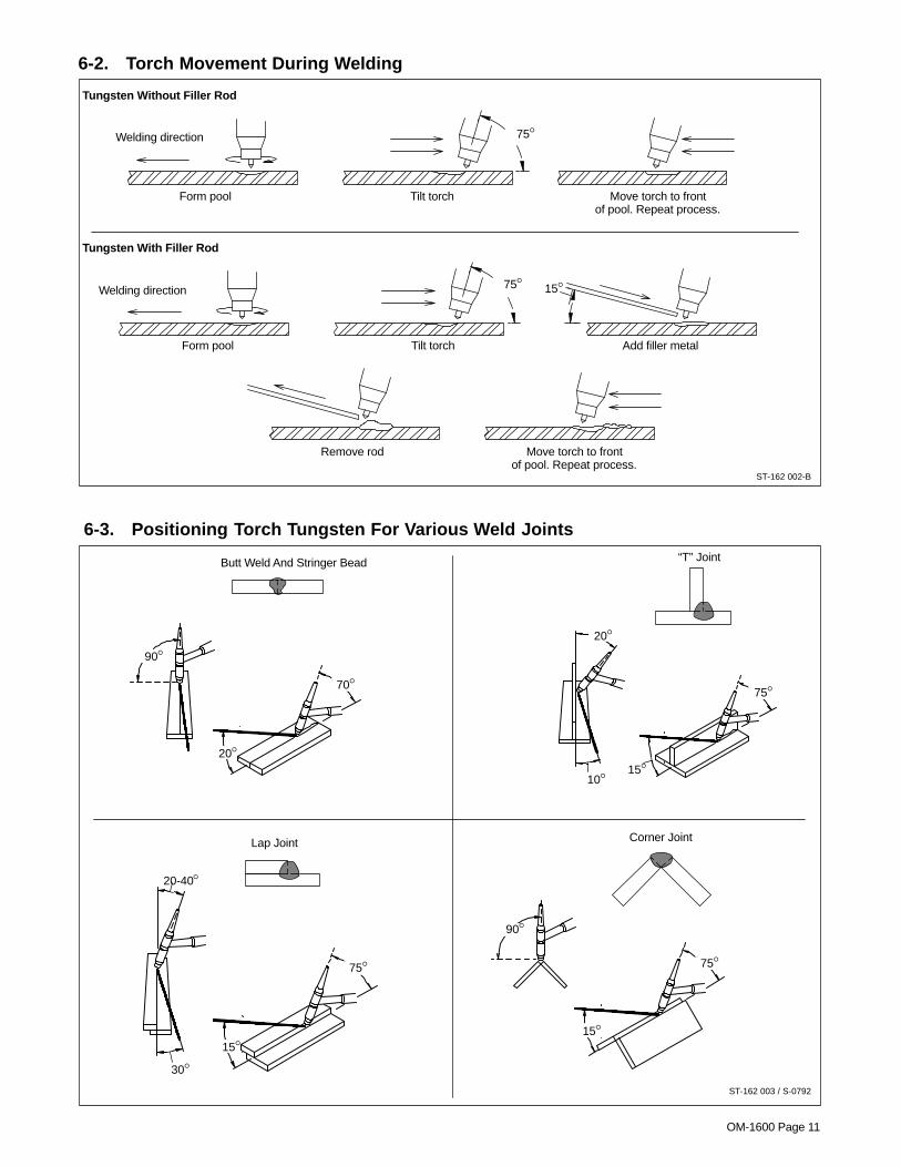
6-2. Torch Movement During Welding
ST-162 002-B
Tungsten Without Filler Rod
Tungsten With Filler Rod
Form pool Tilt torch Move torch to frontof pool. Repeat process.
75°
75°Welding direction
Form pool Tilt torch Add filler metal
Move torch to frontof pool. Repeat process.
Remove rod
Welding direction 15°
6-3. Positioning Torch Tungsten For Various Weld Joints
ST-162 003 / S-0792
75°
70°
90°
20°
20°
10°15°
75°
20-40°
30°15°
75°
90°
15°
Butt Weld And Stringer Bead “T” Joint
Lap Joint Corner Joint
OM-1600 Page 12
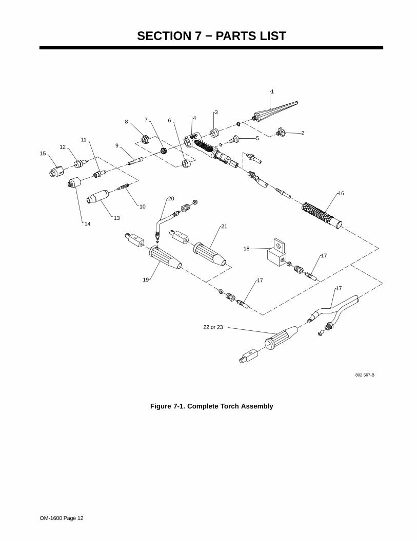
SECTION 7 − PARTS LIST
802 567-B
19
20
17
22 or 23
21
18
17
16
2
43
5
1
14
11
1512
7
10
13
9
8 6
17
Figure 7-1. Complete Torch Assembly
EN
GLI
SH
OM-1600 Page 13
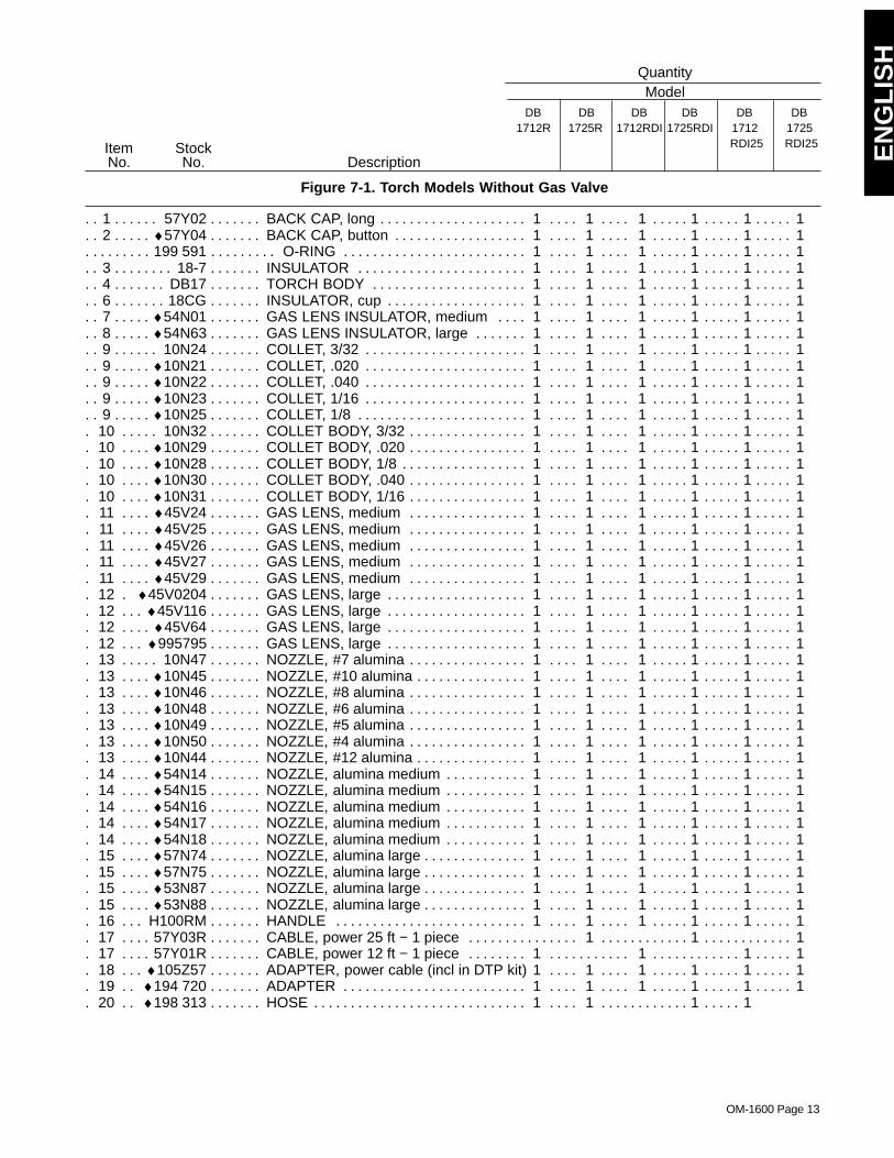
Figure 7-1. Torch Models Without Gas Valve
Quantity
DescriptionStockNo.
ItemNo.
ModelDB
1725RDB
1712RDB
1712RDIDB
1725RDIDB
1712RDI25
DB1725RDI25
1 57Y02 BACK CAP, long 1 1 1 1 1 1. . . . . . . . . . . . . . . . . . . . . . . . . . . . . . . . . . . . . . . . . . . . . . . . . . . . . . . . . . 2 ♦57Y04 BACK CAP, button 1 1 1 1 1 1. . . . . . . . . . . . . . . . . . . . . . . . . . . . . . . . . . . . . . . . . . . . . . . . . . . . . . .
199 591 O-RING 1 1 1 1 1 1. . . . . . . . . . . . . . . . . . . . . . . . . . . . . . . . . . . . . . . . . . . . . . . . . . . . . . . . . . . . . . . . . . 3 18-7 INSULATOR 1 1 1 1 1 1. . . . . . . . . . . . . . . . . . . . . . . . . . . . . . . . . . . . . . . . . . . . . . . . . . . . . . . . . . . . . . . 4 DB17 TORCH BODY 1 1 1 1 1 1. . . . . . . . . . . . . . . . . . . . . . . . . . . . . . . . . . . . . . . . . . . . . . . . . . . . . . . . . . . . 6 18CG INSULATOR, cup 1 1 1 1 1 1. . . . . . . . . . . . . . . . . . . . . . . . . . . . . . . . . . . . . . . . . . . . . . . . . . . . . . . . . . 7 ♦54N01 GAS LENS INSULATOR, medium 1 1 1 1 1 1. . . . . . . . . . . . . . . . . . . . . . . . . . . . . . . . . . . . . . . . . 8 ♦54N63 GAS LENS INSULATOR, large 1 1 1 1 1 1. . . . . . . . . . . . . . . . . . . . . . . . . . . . . . . . . . . . . . . . . . . . 9 10N24 COLLET, 3/32 1 1 1 1 1 1. . . . . . . . . . . . . . . . . . . . . . . . . . . . . . . . . . . . . . . . . . . . . . . . . . . . . . . . . . . . 9 ♦10N21 COLLET, .020 1 1 1 1 1 1. . . . . . . . . . . . . . . . . . . . . . . . . . . . . . . . . . . . . . . . . . . . . . . . . . . . . . . . . . . 9 ♦10N22 COLLET, .040 1 1 1 1 1 1. . . . . . . . . . . . . . . . . . . . . . . . . . . . . . . . . . . . . . . . . . . . . . . . . . . . . . . . . . . 9 ♦10N23 COLLET, 1/16 1 1 1 1 1 1. . . . . . . . . . . . . . . . . . . . . . . . . . . . . . . . . . . . . . . . . . . . . . . . . . . . . . . . . . . 9 ♦10N25 COLLET, 1/8 1 1 1 1 1 1. . . . . . . . . . . . . . . . . . . . . . . . . . . . . . . . . . . . . . . . . . . . . . . . . . . . . . . . . . . .
10 10N32 COLLET BODY, 3/32 1 1 1 1 1 1. . . . . . . . . . . . . . . . . . . . . . . . . . . . . . . . . . . . . . . . . . . . . . . . . . . . 10 ♦10N29 COLLET BODY, .020 1 1 1 1 1 1. . . . . . . . . . . . . . . . . . . . . . . . . . . . . . . . . . . . . . . . . . . . . . . . . . . 10 ♦10N28 COLLET BODY, 1/8 1 1 1 1 1 1. . . . . . . . . . . . . . . . . . . . . . . . . . . . . . . . . . . . . . . . . . . . . . . . . . . . 10 ♦10N30 COLLET BODY, .040 1 1 1 1 1 1. . . . . . . . . . . . . . . . . . . . . . . . . . . . . . . . . . . . . . . . . . . . . . . . . . . 10 ♦10N31 COLLET BODY, 1/16 1 1 1 1 1 1. . . . . . . . . . . . . . . . . . . . . . . . . . . . . . . . . . . . . . . . . . . . . . . . . . . 11 ♦45V24 GAS LENS, medium 1 1 1 1 1 1. . . . . . . . . . . . . . . . . . . . . . . . . . . . . . . . . . . . . . . . . . . . . . . . . . . 11 ♦45V25 GAS LENS, medium 1 1 1 1 1 1. . . . . . . . . . . . . . . . . . . . . . . . . . . . . . . . . . . . . . . . . . . . . . . . . . . 11 ♦45V26 GAS LENS, medium 1 1 1 1 1 1. . . . . . . . . . . . . . . . . . . . . . . . . . . . . . . . . . . . . . . . . . . . . . . . . . . 11 ♦45V27 GAS LENS, medium 1 1 1 1 1 1. . . . . . . . . . . . . . . . . . . . . . . . . . . . . . . . . . . . . . . . . . . . . . . . . . . 11 ♦45V29 GAS LENS, medium 1 1 1 1 1 1. . . . . . . . . . . . . . . . . . . . . . . . . . . . . . . . . . . . . . . . . . . . . . . . . . . 12 ♦45V0204 GAS LENS, large 1 1 1 1 1 1. . . . . . . . . . . . . . . . . . . . . . . . . . . . . . . . . . . . . . . . . . . . . . . . . . . 12 ♦45V116 GAS LENS, large 1 1 1 1 1 1. . . . . . . . . . . . . . . . . . . . . . . . . . . . . . . . . . . . . . . . . . . . . . . . . . . . . 12 ♦45V64 GAS LENS, large 1 1 1 1 1 1. . . . . . . . . . . . . . . . . . . . . . . . . . . . . . . . . . . . . . . . . . . . . . . . . . . . . . 12 ♦995795 GAS LENS, large 1 1 1 1 1 1. . . . . . . . . . . . . . . . . . . . . . . . . . . . . . . . . . . . . . . . . . . . . . . . . . . . . 13 10N47 NOZZLE, #7 alumina 1 1 1 1 1 1. . . . . . . . . . . . . . . . . . . . . . . . . . . . . . . . . . . . . . . . . . . . . . . . . . . . 13 ♦10N45 NOZZLE, #10 alumina 1 1 1 1 1 1. . . . . . . . . . . . . . . . . . . . . . . . . . . . . . . . . . . . . . . . . . . . . . . . . . 13 ♦10N46 NOZZLE, #8 alumina 1 1 1 1 1 1. . . . . . . . . . . . . . . . . . . . . . . . . . . . . . . . . . . . . . . . . . . . . . . . . . . 13 ♦10N48 NOZZLE, #6 alumina 1 1 1 1 1 1. . . . . . . . . . . . . . . . . . . . . . . . . . . . . . . . . . . . . . . . . . . . . . . . . . . 13 ♦10N49 NOZZLE, #5 alumina 1 1 1 1 1 1. . . . . . . . . . . . . . . . . . . . . . . . . . . . . . . . . . . . . . . . . . . . . . . . . . . 13 ♦10N50 NOZZLE, #4 alumina 1 1 1 1 1 1. . . . . . . . . . . . . . . . . . . . . . . . . . . . . . . . . . . . . . . . . . . . . . . . . . . 13 ♦10N44 NOZZLE, #12 alumina 1 1 1 1 1 1. . . . . . . . . . . . . . . . . . . . . . . . . . . . . . . . . . . . . . . . . . . . . . . . . . 14 ♦54N14 NOZZLE, alumina medium 1 1 1 1 1 1. . . . . . . . . . . . . . . . . . . . . . . . . . . . . . . . . . . . . . . . . . . . . . 14 ♦54N15 NOZZLE, alumina medium 1 1 1 1 1 1. . . . . . . . . . . . . . . . . . . . . . . . . . . . . . . . . . . . . . . . . . . . . . 14 ♦54N16 NOZZLE, alumina medium 1 1 1 1 1 1. . . . . . . . . . . . . . . . . . . . . . . . . . . . . . . . . . . . . . . . . . . . . . 14 ♦54N17 NOZZLE, alumina medium 1 1 1 1 1 1. . . . . . . . . . . . . . . . . . . . . . . . . . . . . . . . . . . . . . . . . . . . . . 14 ♦54N18 NOZZLE, alumina medium 1 1 1 1 1 1. . . . . . . . . . . . . . . . . . . . . . . . . . . . . . . . . . . . . . . . . . . . . . 15 ♦57N74 NOZZLE, alumina large 1 1 1 1 1 1. . . . . . . . . . . . . . . . . . . . . . . . . . . . . . . . . . . . . . . . . . . . . . . . . 15 ♦57N75 NOZZLE, alumina large 1 1 1 1 1 1. . . . . . . . . . . . . . . . . . . . . . . . . . . . . . . . . . . . . . . . . . . . . . . . . 15 ♦53N87 NOZZLE, alumina large 1 1 1 1 1 1. . . . . . . . . . . . . . . . . . . . . . . . . . . . . . . . . . . . . . . . . . . . . . . . . 15 ♦53N88 NOZZLE, alumina large 1 1 1 1 1 1. . . . . . . . . . . . . . . . . . . . . . . . . . . . . . . . . . . . . . . . . . . . . . . . . 16 H100RM HANDLE 1 1 1 1 1 1. . . . . . . . . . . . . . . . . . . . . . . . . . . . . . . . . . . . . . . . . . . . . . . . . . . . . . . . . . . . 17 57Y03R CABLE, power 25 ft − 1 piece 1 1 1. . . . . . . . . . . . . . . . . . . . . . . . . . . . . . . . . . . . . . . . . . . . . . . . . . . 17 57Y01R CABLE, power 12 ft − 1 piece 1 1 1 1. . . . . . . . . . . . . . . . . . . . . . . . . . . . . . . . . . . . . . . . . . . . . . . . 18 ♦105Z57 ADAPTER, power cable (incl in DTP kit) 1 1 1 1 1 1. . . . . . . . . . . . . . . . . . . . . . . . . . . . . . . . . . 19 ♦194 720 ADAPTER 1 1 1 1 1 1. . . . . . . . . . . . . . . . . . . . . . . . . . . . . . . . . . . . . . . . . . . . . . . . . . . . . . . . . . 20 ♦198 313 HOSE 1 1 1 1. . . . . . . . . . . . . . . . . . . . . . . . . . . . . . . . . . . . . . . . . . . . . . . . . . . . . . . . . . . .
OM-1600 Page 14
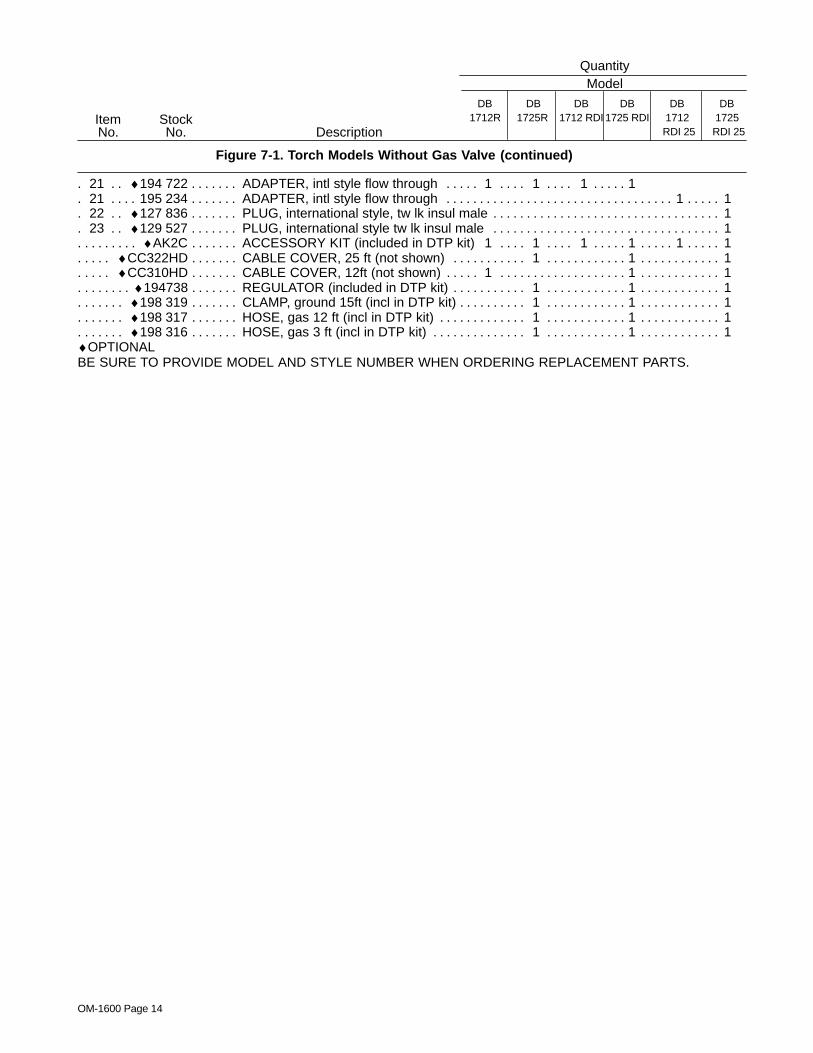
Figure 7-1. Torch Models Without Gas Valve (continued)
Quantity
DescriptionStockNo.
ItemNo.
ModelDB
1725RDB
1712RDB
1712 RDIDB
1725 RDIDB
1712RDI 25
DB1725RDI 25
21 ♦194 722 ADAPTER, intl style flow through 1 1 1 1. . . . . . . . . . . . . . . . . . . . . . . . . . . . 21 195 234 ADAPTER, intl style flow through 1 1. . . . . . . . . . . . . . . . . . . . . . . . . . . . . . . . . . . . . . . . . . . . . . . . . . . 22 ♦127 836 PLUG, international style, tw lk insul male 1. . . . . . . . . . . . . . . . . . . . . . . . . . . . . . . . . . . . . . . . . . . . 23 ♦129 527 PLUG, international style tw lk insul male 1. . . . . . . . . . . . . . . . . . . . . . . . . . . . . . . . . . . . . . . . . . . .
♦AK2C ACCESSORY KIT (included in DTP kit) 1 1 1 1 1 1. . . . . . . . . . . . . . . . . . . . . . . . . . . . . . . . . . . . . . . ♦CC322HD CABLE COVER, 25 ft (not shown) 1 1 1. . . . . . . . . . . . . . . . . . . . . . . . . . . . . . . . . . . . . . . . . . . . . . . ♦CC310HD CABLE COVER, 12ft (not shown) 1 1 1. . . . . . . . . . . . . . . . . . . . . . . . . . . . . . . . . . . . . . . . . . . . . . . .
♦194738 REGULATOR (included in DTP kit) 1 1 1. . . . . . . . . . . . . . . . . . . . . . . . . . . . . . . . . . . . . . . . . . . . . . . . . . ♦198 319 CLAMP, ground 15ft (incl in DTP kit) 1 1 1. . . . . . . . . . . . . . . . . . . . . . . . . . . . . . . . . . . . . . . . . . . . . . . . ♦198 317 HOSE, gas 12 ft (incl in DTP kit) 1 1 1. . . . . . . . . . . . . . . . . . . . . . . . . . . . . . . . . . . . . . . . . . . . . . . . . . . ♦198 316 HOSE, gas 3 ft (incl in DTP kit) 1 1 1. . . . . . . . . . . . . . . . . . . . . . . . . . . . . . . . . . . . . . . . . . . . . . . . . . . .
♦OPTIONALBE SURE TO PROVIDE MODEL AND STYLE NUMBER WHEN ORDERING REPLACEMENT PARTS.
EN
GLI
SH
OM-1600 Page 15
Description
Quantity
StockNo.
ItemNo.
Model
17V12R
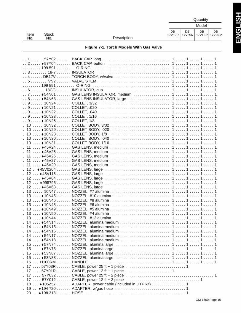
Figure 7-1. Torch Models With Gas Valve
17V12-2DB DB
17V25RDB
17V25-2DB
1 57Y02 BACK CAP, long 1 1 1 1. . . . . . . . . . . . . . . . . . . . . . . . . . . . . . . . . . . . . . . . . . . . . . . . . . . . . . . . . . . . . . . . 2 ♦57Y04 BACK CAP, button 1 1 1 1. . . . . . . . . . . . . . . . . . . . . . . . . . . . . . . . . . . . . . . . . . . . . . . . . . . . . . . . . . . . .
199 591 O-RING 1 1 1 1. . . . . . . . . . . . . . . . . . . . . . . . . . . . . . . . . . . . . . . . . . . . . . . . . . . . . . . . . . . . . . . . . . . . . . . . 3 18-7 INSULATOR 1 1 1 1. . . . . . . . . . . . . . . . . . . . . . . . . . . . . . . . . . . . . . . . . . . . . . . . . . . . . . . . . . . . . . . . . . . . . 4 DB17V TORCH BODY, w/valve 1 1 1 1. . . . . . . . . . . . . . . . . . . . . . . . . . . . . . . . . . . . . . . . . . . . . . . . . . . . . . . . . . 5 VS2 VALVE STEM 1 1 1 1. . . . . . . . . . . . . . . . . . . . . . . . . . . . . . . . . . . . . . . . . . . . . . . . . . . . . . . . . . . . . . . . . . . .
199 591 O-RING 1 1 1 1. . . . . . . . . . . . . . . . . . . . . . . . . . . . . . . . . . . . . . . . . . . . . . . . . . . . . . . . . . . . . . . . . . . . . . . . 6 18CG INSULATOR, cup 1 1 1 1. . . . . . . . . . . . . . . . . . . . . . . . . . . . . . . . . . . . . . . . . . . . . . . . . . . . . . . . . . . . . . . . 7 ♦54N01 GAS LENS INSULATOR, medium 1 1 1 1. . . . . . . . . . . . . . . . . . . . . . . . . . . . . . . . . . . . . . . . . . . . . . . 8 ♦54N63 GAS LENS INSULATOR, large 1 1 1 1. . . . . . . . . . . . . . . . . . . . . . . . . . . . . . . . . . . . . . . . . . . . . . . . . . 9 10N24 COLLET, 3/32 1 1 1 1. . . . . . . . . . . . . . . . . . . . . . . . . . . . . . . . . . . . . . . . . . . . . . . . . . . . . . . . . . . . . . . . . . 9 ♦10N21 COLLET, .020 1 1 1 1. . . . . . . . . . . . . . . . . . . . . . . . . . . . . . . . . . . . . . . . . . . . . . . . . . . . . . . . . . . . . . . . . 9 ♦10N22 COLLET, .040 1 1 1 1. . . . . . . . . . . . . . . . . . . . . . . . . . . . . . . . . . . . . . . . . . . . . . . . . . . . . . . . . . . . . . . . . 9 ♦10N23 COLLET, 1/16 1 1 1 1. . . . . . . . . . . . . . . . . . . . . . . . . . . . . . . . . . . . . . . . . . . . . . . . . . . . . . . . . . . . . . . . . 9 ♦10N25 COLLET, 1/8 1 1 1 1. . . . . . . . . . . . . . . . . . . . . . . . . . . . . . . . . . . . . . . . . . . . . . . . . . . . . . . . . . . . . . . . . .
10 10N32 COLLET BODY, 3/32 1 1 1 1. . . . . . . . . . . . . . . . . . . . . . . . . . . . . . . . . . . . . . . . . . . . . . . . . . . . . . . . . . 10 ♦10N29 COLLET BODY, .020 1 1 1 1. . . . . . . . . . . . . . . . . . . . . . . . . . . . . . . . . . . . . . . . . . . . . . . . . . . . . . . . . 10 ♦10N28 COLLET BODY, 1/8 1 1 1 1. . . . . . . . . . . . . . . . . . . . . . . . . . . . . . . . . . . . . . . . . . . . . . . . . . . . . . . . . . 10 ♦10N30 COLLET BODY, .040 1 1 1 1. . . . . . . . . . . . . . . . . . . . . . . . . . . . . . . . . . . . . . . . . . . . . . . . . . . . . . . . . 10 ♦10N31 COLLET BODY, 1/16 1 1 1 1. . . . . . . . . . . . . . . . . . . . . . . . . . . . . . . . . . . . . . . . . . . . . . . . . . . . . . . . . 11 ♦45V24 GAS LENS, medium 1 1 1 1. . . . . . . . . . . . . . . . . . . . . . . . . . . . . . . . . . . . . . . . . . . . . . . . . . . . . . . . . 11 ♦45V25 GAS LENS, medium 1 1 1 1. . . . . . . . . . . . . . . . . . . . . . . . . . . . . . . . . . . . . . . . . . . . . . . . . . . . . . . . . 11 ♦45V26 GAS LENS, medium 1 1 1 1. . . . . . . . . . . . . . . . . . . . . . . . . . . . . . . . . . . . . . . . . . . . . . . . . . . . . . . . . 11 ♦45V27 GAS LENS, medium 1 1 1 1. . . . . . . . . . . . . . . . . . . . . . . . . . . . . . . . . . . . . . . . . . . . . . . . . . . . . . . . . 11 ♦45V29 GAS LENS, medium 1 1 1 1. . . . . . . . . . . . . . . . . . . . . . . . . . . . . . . . . . . . . . . . . . . . . . . . . . . . . . . . . 12 ♦45V0204 GAS LENS, large 1 1 1 1. . . . . . . . . . . . . . . . . . . . . . . . . . . . . . . . . . . . . . . . . . . . . . . . . . . . . . . . . 12 ♦45V116 GAS LENS, large 1 1 1 1. . . . . . . . . . . . . . . . . . . . . . . . . . . . . . . . . . . . . . . . . . . . . . . . . . . . . . . . . . . 12 ♦45V64 GAS LENS, large 1 1 1 1. . . . . . . . . . . . . . . . . . . . . . . . . . . . . . . . . . . . . . . . . . . . . . . . . . . . . . . . . . . . 12 ♦995795 GAS LENS, large 1 1 1 1. . . . . . . . . . . . . . . . . . . . . . . . . . . . . . . . . . . . . . . . . . . . . . . . . . . . . . . . . . . 12 ♦45V63 GAS LENS, large 1 1 1 1. . . . . . . . . . . . . . . . . . . . . . . . . . . . . . . . . . . . . . . . . . . . . . . . . . . . . . . . . . . . 13 10N47 NOZZEL, #7 alumina 1 1 1 1. . . . . . . . . . . . . . . . . . . . . . . . . . . . . . . . . . . . . . . . . . . . . . . . . . . . . . . . . . 13 ♦10N45 NOZZEL, #10 alumina 1 1 1 1. . . . . . . . . . . . . . . . . . . . . . . . . . . . . . . . . . . . . . . . . . . . . . . . . . . . . . . . 13 ♦10N46 NOZZEL, #8 alumina 1 1 1 1. . . . . . . . . . . . . . . . . . . . . . . . . . . . . . . . . . . . . . . . . . . . . . . . . . . . . . . . . 13 ♦10N48 NOZZEL, #6 alumina 1 1 1 1. . . . . . . . . . . . . . . . . . . . . . . . . . . . . . . . . . . . . . . . . . . . . . . . . . . . . . . . . 13 ♦10N49 NOZZEL, #5 alumina 1 1 1 1. . . . . . . . . . . . . . . . . . . . . . . . . . . . . . . . . . . . . . . . . . . . . . . . . . . . . . . . . 13 ♦10N50 NOZZEL, #4 alumina 1 1 1 1. . . . . . . . . . . . . . . . . . . . . . . . . . . . . . . . . . . . . . . . . . . . . . . . . . . . . . . . . 13 ♦10N44 NOZZEL, #12 alumina 1 1 1 1. . . . . . . . . . . . . . . . . . . . . . . . . . . . . . . . . . . . . . . . . . . . . . . . . . . . . . . . 14 ♦54N14 NOZZEL, alumina medium 1 1 1 1. . . . . . . . . . . . . . . . . . . . . . . . . . . . . . . . . . . . . . . . . . . . . . . . . . . . 14 ♦54N15 NOZZEL, alumina medium 1 1 1 1. . . . . . . . . . . . . . . . . . . . . . . . . . . . . . . . . . . . . . . . . . . . . . . . . . . . 14 ♦54N16 NOZZEL, alumina medium 1 1 1 1. . . . . . . . . . . . . . . . . . . . . . . . . . . . . . . . . . . . . . . . . . . . . . . . . . . . 14 ♦54N17 NOZZEL, alumina medium 1 1 1 1. . . . . . . . . . . . . . . . . . . . . . . . . . . . . . . . . . . . . . . . . . . . . . . . . . . . 14 ♦54N18 NOZZEL, alumina medium 1 1 1 1. . . . . . . . . . . . . . . . . . . . . . . . . . . . . . . . . . . . . . . . . . . . . . . . . . . . 15 ♦57N74 NOZZEL, alumina large 1 1 1 1. . . . . . . . . . . . . . . . . . . . . . . . . . . . . . . . . . . . . . . . . . . . . . . . . . . . . . . 15 ♦57N75 NOZZEL, alumina large 1 1 1 1. . . . . . . . . . . . . . . . . . . . . . . . . . . . . . . . . . . . . . . . . . . . . . . . . . . . . . . 15 ♦53N87 NOZZEL, alumina large 1 1 1 1. . . . . . . . . . . . . . . . . . . . . . . . . . . . . . . . . . . . . . . . . . . . . . . . . . . . . . . 15 ♦53N88 NOZZEL, alumina large 1 1 1 1. . . . . . . . . . . . . . . . . . . . . . . . . . . . . . . . . . . . . . . . . . . . . . . . . . . . . . . 16 H100RM HANDLE 1 1 1 1. . . . . . . . . . . . . . . . . . . . . . . . . . . . . . . . . . . . . . . . . . . . . . . . . . . . . . . . . . . . . . . . . . 17 57Y03R CABLE, power 25 ft − 1 piece 1. . . . . . . . . . . . . . . . . . . . . . . . . . . . . . . . . . . . . . . . . . 17 57Y01R CABLE, power 12 ft − 1 piece 1. . . . . . . . . . . . . . . . . . . . . . . . . . . . . . . . . . 17 57Y032 CABLE, power 25 ft − 2 piece 1. . . . . . . . . . . . . . . . . . . . . . . . . . . . . . . . . . . . . . . . . . . . . . . . . . . . . . . . 17 57Y012 CABLE, power 12 ft − 2 piece 1. . . . . . . . . . . . . . . . . . . . . . . . . . . . . . . . . . . . . . . . . . . . . . . . . 18 ♦105Z57 ADAPTER, power cable (included in DTP kit) 1. . . . . . . . . . . . . . . . . . . . . . . . . . . . 19 ♦194 720 ADAPTER, w/gas hose 1. . . . . . . . . . . . . . . . . . . . . . . . . . . . . . . . . . . . . . . . . . . . . . 20 ♦198 313 HOSE 1. . . . . . . . . . . . . . . . . . . . . . . . . . . . . . . . . . . . . . . . . . . . . . . . . . . . . . . . . . . . .
OM-1600 Page 16
DescriptionStockNo.
ItemNo.
Figure 7-1. Torch Models With Gas Valve (continued)
Quantity
Model
17V12R 17V12-2DB DB
17V25RDB
17V25-2DB
22 ♦127 836 PLUG, international style, tw lk insul male 1 1 1. . . . . . . . . . . . . . . . . . . . . . . . . . . . . . . . . . . . . . . 23 ♦129 527 PLUG, international style tw lk insul male 1 1 1. . . . . . . . . . . . . . . . . . . . . . . . . . . . . . . . . . . . . . .
♦AK2C ACCESSORY KIT (included in DTP kit) 1 1 1 1. . . . . . . . . . . . . . . . . . . . . . . . . . . . . . . . . . . . . . . . . . . . . ♦CC322HD CABLE COVER, 25 ft (not shown) 1 1. . . . . . . . . . . . . . . . . . . . . . . . . . . . . . . . . . . . . . . . . . . . . . . . . . ♦CC310HD CABLE COVER, 12ft (not shown) 1 1. . . . . . . . . . . . . . . . . . . . . . . . . . . . . . . . . . . . . . . . . . .
♦194738 REGULATOR (included in DTP kit) 1. . . . . . . . . . . . . . . . . . . . . . . . . . . . . . . . . . . . . . . . . ♦198 319 CLAMP, ground 15ft (incl in DTP kit) 1. . . . . . . . . . . . . . . . . . . . . . . . . . . . . . . . . . . . . . . ♦198 317 HOSE, gas 12 ft (incl in DTP kit) 1. . . . . . . . . . . . . . . . . . . . . . . . . . . . . . . . . . . . . . . . . . ♦198 316 HOSE, gas 3 ft (incl in DTP kit) 1. . . . . . . . . . . . . . . . . . . . . . . . . . . . . . . . . . . . . . . . . . .
♦OPTIONALBE SURE TO PROVIDE MODEL AND STYLE NUMBER WHEN ORDERING REPLACEMENT PARTS.

Notes

Notes
Warranty Questions?
Call1-800-4-A-MILLERfor your localMiller distributor.
miller_warr 6/04
Your distributor also givesyou ...
ServiceYou always get the fast,reliable response youneed. Most replacementparts can be in yourhands in 24 hours.
SupportNeed fast answers to thetough welding questions?Contact your distributor.The expertise of thedistributor and Miller isthere to help you, everystep of the way.
Effective January 1, 2004(Equipment with a serial number preface of “LE” or newer)This limited warranty supersedes all previous Miller warranties and is exclusive with no other
guarantees or warranties expressed or implied.
LIMITED WARRANTY − Subject to the terms and conditionsbelow, Miller Electric Mfg. Co., Appleton, Wisconsin, warrants toits original retail purchaser that new Miller equipment sold afterthe effective date of this limited warranty is free of defects inmaterial and workmanship at the time it is shipped by Miller.THIS WARRANTY IS EXPRESSLY IN LIEU OF ALL OTHERWARRANTIES, EXPRESS OR IMPLIED, INCLUDING THEWARRANTIES OF MERCHANTABILITY AND FITNESS.
Within the warranty periods listed below, Miller will repair orreplace any warranted parts or components that fail due to suchdefects in material or workmanship. Miller must be notified inwriting within thirty (30) days of such defect or failure, at whichtime Miller will provide instructions on the warranty claimprocedures to be followed.
Miller shall honor warranty claims on warranted equipmentlisted below in the event of such a failure within the warrantytime periods. All warranty time periods start on the date that theequipment was delivered to the original retail purchaser, or oneyear after the equipment is sent to a North American distributoror eighteen months after the equipment is sent to anInternational distributor.
1. 5 Years Parts — 3 Years Labor
* Original main power rectifiers* Inverters (input and output rectifiers only)
2. 3 Years — Parts and Labor
* Transformer/Rectifier Power Sources* Plasma Arc Cutting Power Sources* Semi-Automatic and Automatic Wire Feeders* Inverter Power Sources (Unless Otherwise Stated)* Water Coolant Systems (Integrated)* Intellitig* Maxstar 150* Engine Driven Welding Generators
(NOTE: Engines are warranted separately bythe engine manufacturer.)
3. 1 Year — Parts and Labor Unless Specified
* DS-2 Wire Feeder* Motor Driven Guns (w/exception of Spoolmate
Spoolguns)* Process Controllers* Positioners and Controllers* Automatic Motion Devices* RFCS Foot Controls* Induction Heating Power Sources and Coolers* Water Coolant Systems (Non-Integrated)* Flowgauge and Flowmeter Regulators (No Labor)* HF Units* Grids* Maxstar 85, 140* Spot Welders* Load Banks* Arc Stud Power Sources & Arc Stud Guns* Racks* Running Gear/Trailers* Plasma Cutting Torches (except APT & SAF
Models)* Field Options
(NOTE: Field options are covered under TrueBlue for the remaining warranty period of theproduct they are installed in, or for a minimum ofone year — whichever is greater.)
4. 6 Months — Batteries
5. 90 Days — Parts
* MIG Guns/TIG Torches
* Induction Heating Coils and Blankets
* APT & SAF Model Plasma Cutting Torches
* Remote Controls
* Accessory Kits
* Replacement Parts (No labor)
* Spoolmate Spoolguns
* Canvas Covers
Miller’s True Blue Limited Warranty shall not apply to:
1. Consumable components; such as contact tips,cutting nozzles, contactors, brushes, slip rings,relays or parts that fail due to normal wear. (Exception:brushes, slip rings, and relays are covered on Bobcat,Trailblazer, and Legend models.)
2. Items furnished by Miller, but manufactured by others,such as engines or trade accessories. These items arecovered by the manufacturer’s warranty, if any.
3. Equipment that has been modified by any party other thanMiller, or equipment that has been improperly installed,improperly operated or misused based upon industrystandards, or equipment which has not had reasonableand necessary maintenance, or equipment which hasbeen used for operation outside of the specifications for theequipment.
MILLER PRODUCTS ARE INTENDED FOR PURCHASE ANDUSE BY COMMERCIAL/INDUSTRIAL USERS ANDPERSONS TRAINED AND EXPERIENCED IN THE USE ANDMAINTENANCE OF WELDING EQUIPMENT.
In the event of a warranty claim covered by this warranty, theexclusive remedies shall be, at Miller’s option: (1) repair; or (2)replacement; or, where authorized in writing by Miller inappropriate cases, (3) the reasonable cost of repair orreplacement at an authorized Miller service station; or (4)payment of or credit for the purchase price (less reasonabledepreciation based upon actual use) upon return of the goods atcustomer’s risk and expense. Miller’s option of repair orreplacement will be F.O.B., Factory at Appleton, Wisconsin, orF.O.B. at a Miller authorized service facility as determined byMiller. Therefore no compensation or reimbursement fortransportation costs of any kind will be allowed.
TO THE EXTENT PERMITTED BY LAW, THE REMEDIESPROVIDED HEREIN ARE THE SOLE AND EXCLUSIVEREMEDIES. IN NO EVENT SHALL MILLER BE LIABLE FORDIRECT, INDIRECT, SPECIAL, INCIDENTAL ORCONSEQUENTIAL DAMAGES (INCLUDING LOSS OFPROFIT), WHETHER BASED ON CONTRACT, TORT ORANY OTHER LEGAL THEORY.
ANY EXPRESS WARRANTY NOT PROVIDED HEREIN ANDANY IMPLIED WARRANTY, GUARANTY ORREPRESENTATION AS TO PERFORMANCE, AND ANYREMEDY FOR BREACH OF CONTRACT TORT OR ANYOTHER LEGAL THEORY WHICH, BUT FOR THISPROVISION, MIGHT ARISE BY IMPLICATION, OPERATIONOF LAW, CUSTOM OF TRADE OR COURSE OF DEALING,INCLUDING ANY IMPLIED WARRANTY OFMERCHANTABILITY OR FITNESS FOR PARTICULARPURPOSE, WITH RESPECT TO ANY AND ALL EQUIPMENTFURNISHED BY MILLER IS EXCLUDED AND DISCLAIMEDBY MILLER.
Some states in the U.S.A. do not allow limitations of how long animplied warranty lasts, or the exclusion of incidental, indirect,special or consequential damages, so the above limitation orexclusion may not apply to you. This warranty provides specificlegal rights, and other rights may be available, but may varyfrom state to state.
In Canada, legislation in some provinces provides for certainadditional warranties or remedies other than as stated herein,and to the extent that they may not be waived, the limitationsand exclusions set out above may not apply. This LimitedWarranty provides specific legal rights, and other rights may beavailable, but may vary from province to province.

PRINTED IN USA 2004 Miller Electric Mfg. Co. 10/04
Miller Electric Mfg. Co.An Illinois Tool Works Company1635 West Spencer StreetAppleton, WI 54914 USA
International Headquarters−USAUSA Phone: 920-735-4505 Auto-AttendedUSA & Canada FAX: 920-735-4134International FAX: 920-735-4125
European Headquarters −United KingdomPhone: 44 (0) 1204-593493FAX: 44 (0) 1204-598066
www.MillerWelds.com
Model Name Serial/Style Number
Purchase Date (Date which equipment was delivered to original customer.)
Distributor
Address
City
State Zip
Please complete and retain with your personal records.
Always provide Model Name and Serial/Style Number.
Contact a DISTRIBUTOR or SERVICE AGENCY near you.
Welding Supplies and Consumables
Options and Accessories
Personal Safety Equipment
Service and Repair
Replacement Parts
Training (Schools, Videos, Books)
Technical Manuals (Servicing Informationand Parts)
Circuit Diagrams
Welding Process Handbooks
Contact the Delivering Carrier to:
For Service
Owner’s Record
File a claim for loss or damage duringshipment.
For assistance in filing or settling claims, contactyour distributor and/or equipment manufacturer’sTransportation Department.
Contact your Distributor for:
To locate a Distributor or Service Agency visitwww.millerwelds.com or call 1-800-4-A-Miller