Embed Size (px)
Citation preview
DiaLog Elite
Modbus Master Interface Manual
Publish Date: August 1, 2003 Document Version 1.2


Copyright and Trademark Information
All Pages Copyright © 2001 Antx, inc. All Rights Reserved.
U.S. Government Users Restricted Rights. Use, duplication, or disclosure by the Government is subject to restrictions as set forth in applicable laws and regulations. Use of the materials by the Government constitutes acknowledgment of Antx's proprietary rights in them. This manual may contain other proprietary notices and copyright information that should be observed.
Information in this document is subject to change without notice. The software described in this document is furnished under a license agreement or nondisclosure agreement. The software may be used or copied only in accordance with the terms of those agreements. No part of this publication may be reproduced, stored in a retrieval system, or transmitted in any form or any means electronic or mechanical, including photocopying and recording for any purpose other than the purchaser’s personal use without the written permission of Antx, inc.


Version 1.2
Contents About this Guide ........................................................................................................................................................................iii About this Guide ........................................................................................................................................................................iii
Who Should Use this Guide ..................................................................................................................................................iii How to Use this Guide ..........................................................................................................................................................iii Conventions Used in this Guide........................................................................................................................................... iv
1 What is the Modbus Master Interface Option?.....................................................................................................1
2 Initializing the Modbus Master Interface Option ..................................................................................................3 From the front panel................................................................................................................................................................... 4 Remotely over a phone.............................................................................................................................................................. 5
3 Mapping Elite channels to Modbus registers.......................................................................................................7 Programming channel parameters............................................................................................................................................. 9
Digital Inputs ....................................................................................................................................................................... 10 Analog Inputs ...................................................................................................................................................................... 11 Relay Outputs ..................................................................................................................................................................... 13
4 Running the Modbus Master Interface................................................................................................................15 Viewing Alarms ........................................................................................................................................................................ 15
Modbus Comm. Failure Alarm ............................................................................................................................................ 16 I/O channel alarm................................................................................................................................................................ 16
Confirming Modbus Slave Communication.............................................................................................................................. 16

DiaLog Elite PLC Interface Manual
. ii Version 1.2 © Antx, inc. 2001

DiaLog Elite PLC Interface Manual
© Antx, inc. 2001 Version 1.2 iii
About this Guide This guide is intended to describe how to install and configure the DiaLog Elite PLC
Interface Option. The PLC Interface Option allows the Elite to act as a Modbus Master to communicate with a PLC as a Modbus Slave.
Who Should Use this Guide
This manual is intended for use by operations technicians who are responsible for installing and configure the DiaLog Elite hardware.
How to Use this Guide
This guide is divided into the following chapters:
Chapter 1, What is the Modbus Master Interface Option. Describes the capabilities of the Modbus Master interface option.
Chapter 2, Initializing the Modbus Master Interface Option. Describes how to set up the Interface for operation with a PLC or Modbus I/O.
Chapter 3, Mapping Elite channels to PLC registers. Describes how to program the Elite I/O channels to reference Modbus Slave registers.
Chapter 4, Running the Modbus Master Interface. Describes how to view the current status of the Modbus Master Interface in real-time.
In this manual, the terms DiaLog Elite and DiaLog are used interchangeably.

DiaLog Elite PLC Interface Manual
Conventions Used in this Guide
To help you understand the information in this guide, a consistent set of documentation conventions are used to represent certain material.
The following table describes the typographic conventions used in this guide to help you locate and interpret information.
Convention Description
Italic text Indicates a parameter that you can set.
EXAMPLE:
DiaLog accepts a return call as an acknowledgement of all alarms if you enable the Call In Acknowledge feature. The call must come during the 30-second Between Calls Delay, or DiaLog calls the next number on the list.
Courier font Indicates messages shown on the DiaLog display or information printed on reports.
EXAMPLE:
If parameters for channel 7 were set up as follows, then this message appears on the pager’s display:
NORTHWEST FACILITY-7 NO 2 TANK LEVEL HI 101.5 GALS
“Text enclosed in quotes”.
Indicates messages that DiaLog speaks.
EXAMPLE:
The power on diagnostics take about 45 seconds to complete, followed by the voice announcing:
“This is DiaLog Elite. Program mode activated. System is armed. System ready. Enter selection.”
Picture of key from front panel
Home , 1Prog , 2
Run , #Enter , Ack
Clear
ArmReset ,
DisarmBksp , 0
Status , 5SpkrPh
These keys are used when a special key on the front panel must be pressed to accomplish a task.
EXAMPLE:
Press Home2Run to enter RUN mode.
. iv Version 1.2 © Antx, inc. 2001

DiaLog Elite PLC Interface Manual
© Antx, inc. 2001 Version 1.2 v
Convention Description
Small rectangular representation of key
0. 1 2 3. 4. 5. .6 7. 8. 9. 0. *. .#. F1. F2. F3. F4.
Indicates keys to press when entering parameter values at the keypad or when communicating with the DiaLog via a touch-tone telephone.
EXAMPLE 1:
The person answering the call acknowledges it by pressing the .* , 8 or 9 key on a Touch-Tone telephone.
EXAMPLE 2:
In Chapter 7, Programming the DiaLog Elite, 0 - 2 in the What you Enter column means to enter a value between 0 and 2.
Small rounded rectangular representation of a key
These keys are used in Chapter 7, Programming the DiaLog Elite, to indicate menu selections. These are used in both the Road Map and the Menu Sequence headings.
0 1 2 3
EXAMPLE:
4 5 6 7 9 0 3
8 9
Means to press the keys 9, 0 and 3 to reach the command.
Road Map This heading and icon is used at the beginning of a function description to indicate the complete key sequence that the user takes to reach the function being described. The Road Map also includes other parameters within that function.
EXAMPLE:
Channel Configuration
Relay Output
Channels
Channel Number
9
3
n n
0 Pulse Duration [0-65535] 1 De-energize Relay on Ack. [0-1] 2 Channel Mode [0-1] 3 Channel Alpha ID [A-Z, 0-9]
Description This heading and icon is used to present an overview of the function being discussed.
Field Summary This heading and icon is used to list all parameters that must be entered for the function. The heading includes the name of the Field, Range of values that can be entered, and Factory Setting.
EXAMPLE:
Field Range Factory Setting Alarm Delay 0-65535 seconds 3

DiaLog Elite PLC Interface Manual
. vi Version 1.2 © Antx, inc. 2001
Convention Description
Menu Sequence This heading and icon is used to list the menu keys that must be pressed to reach the command being discussed.
CAUTION This heading and icon in the margin indicates a special concern that you should take into consideration when performing an action. Cautions not followed could result in danger.
WARNING! This heading and icon in the margin indicates advice to heed when performing an action. Warnings not followed could result in damage to the equipment or personal harm.
NOTE This heading and icon in the margin indicates any exceptions or additional points to the topic being discussed.
EXAMPLE This heading and icon in the margin indicates that the text contains an illustration of a point being discussed.

DiaLog Elite PLC Interface Manual
1 What is the Modbus Master Interface Option? The Modbus Master Interface enables the DiaLog Elite to read input values from a PLC or
Modbus Slave device and write relay control values to a PLC or Modbus Slave device. The connection uses the RS-232 serial connector on the Elite. The protocol is Modbus RTU, where the Elite is the Master and the PLC or Modbus I/O is the Slave. The option supports a combination of up to 72 total I/O channels – up to 48 of which can be physical I/O in the Elite. The I/O in the Modbus Slave can be any combination of analog (holding registers) or digital points (coils). Values that are read from the Modbus Slave are interpreted by the Elite the same as if they were physical I/O in the Elite. All the alarm and control logic within the Elite operate on data coming from Modbus registers. The communications link between the Elite and the PLC is monitored several times a second. If the communications link stops functioning after repeated attempts, a Communications Channel (06) alarm is initiated. This alarm is treated exactly like any other system alarm allowing the system to call out, drive local relay or issue reports.
The Modbus Master option does not require the Modbus RTU Option in the Elite, but both can be installed. When both are installed, the Elite acts as a Modbus Master to the PLC and a Modbus Slave to your SCADA software or to another Elite.
© Antx, inc. 2001 Version 1.2 1

DiaLog Elite PLC Interface Manual
. 2 Version 1.2 © Antx, inc. 2001

DiaLog Elite PLC Interface Manual
2 Initializing the Modbus Master Interface Option This chapter provides information for setting up the PLC Interface for operation with a
PLC or Modbus Slave connected to the RS-232 port. The RS-232 port is a male DB9 connection configured as a DTE device. The pin out of this connector is:
Pin 2 RX Pin 3 TX Pin 5 GND
The Modbus Master Interface is setup by defining the: • Serial port baud rate – default is 38400 • PLC/Modbus ID – default is 1 • Defining Elite I/O slots to be identified as PLC/Modbus I/O – default is that no slots
are enabled as PLC I/O slots. There are 8 PLC I/O channels per Slot. You can enable as many slots as you have purchased. For example, if you purchased a 32-channel PLC configuration, then you can enable any 4 slots which do not have physical I/O cards attached.
All of these can be defined either through the integral keypad or remotely via a phone.
© Antx, inc. 2001 Version 1.2 3
DiaLog Elite PLC Interface Manual
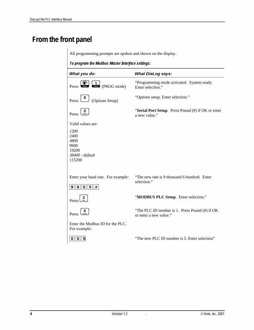
From the front panel All programming prompts are spoken and shown on the display.
To program the Modbus Master Interface settings:
What you do: What DiaLog says:
Press Home1
PROG (PROG mode) “Programming mode activated. System ready. Enter selection.”
Press
8 (Options Setup)
“Options setup. Enter selection.”
Press 0
Status
Valid values are:
1200 2400 4800 9600 19200 38400 - default 115200
“Serial Port Setup. Press Pound (#) if OK or enter a new value.”
Enter your baud rate. For example:
9 6 0 0 #.
“The new rate is 9 thousand 6 hundred. Enter selection.”
Press2Run
“MODBUS PLC Setup. Enter selection.”
Press 0
Status
Enter the Modbus ID for the PLC. For example:
“The PLC ID number is 1. Press Pound (#) if OK or enter a new value.”
0 0 5 “The new PLC ID number is 5. Enter selection”
. 4 Version 1.2 © Antx, inc. 2001

DiaLog Elite PLC Interface Manual
Press 1
PROG
To enable PLC I/O slots in the Elite:
Valid values are: 1 for slot 10 2 for slot 20
3 for slot 30 4 for slot 40
5 for slot 50 6 for slot 60
7 for slot 70 8 for slot 80
9 for slot 90
“ Enter Slot Number”
For example:
3
“MODBUS slot 3 is disabled. Press # if OK, 0 to disable or 1 to enable.”
1 “MODBUS slot 3 is enabled. Enter Slot Number”
Repeat entering Slot numbers as needed. When finished:
Press Home
“Program mode activated. System ready. Enter selection.
Remotely over a phone The sequence is exactly the same as from the front panel except that instead of pressing the
HOME key, press *. 6.
© Antx, inc. 2001 Version 1.2 5


DiaLog Elite PLC Interface Manual
3 Mapping Elite channels to Modbus registers I/O channels in the Elite are mapped to PLC/Modbus registers by providing two (2) pieces
of information:
• Register type – which corresponds to Function Code
• Register number – number of the register for the particular Function Code
Elite Register
Type
Description Type of channel in the Elite
Modbus Function
Code
1 Read Coil Status Digital 01 2 Read Input Status Digital 02 3 Read Holding Register Analog 03 4 Read Input Register Analog 04 5 Write Coil Relay 05
The register type and register number are defined in the Channel Configuration section of the Elite.
NOTE Register types (Function Codes) can be mixed within a single slot in the Elite.
For example,
If Slot 70 is a PLC/Modbus I/O slot, channel 71 can be a Read Coil Status (1), channel 72 can be a Holding (3), and channel 73 can be a Write Coil (5).
The following example shows the steps to identify channels in the Elite that map to PLC channels:
Elite Channel PLC register
71 (1)0050
72 (3)0121
73 (5)1001
© Antx, inc. 2001 Version 1.2 7

DiaLog Elite PLC Interface Manual
To program Elite channel mappings to PLC registers:
What you do: What DiaLog says:
Press Home1
PROG (PROG mode) “Programming mode activated. System ready. Enter selection.”
Press
9 (Channel Configuration)
“Channel Configuration. Enter channel number.”
Press 7. 1.
Valid values are: 1 – 5 for function codes (01 – 05)
“The register type is unknown. Press # if OK or enter a new selection.”
Press 1.
“The new register type is coil. Register number is 0. Press # if OK or enter a new value.”
Press 5. 0. #. “The new register number is 50. Digital input channel 71. Enter selection.”
Press #. “Channel Configuration. Enter channel number”
Press 7. 2. “The register type is unknown. Press # if OK or enter a new selection.”
Press 3.
“The new register type is holding. Register number is 0. Press # if OK or enter a new value.”
Press 1. 2. 1. #.
“The new register number is 121. Analog input channel 72. Enter selection.”
Press #. “Channel Configuration. Enter channel number”
Press 7. 3. “The register type is unknown. Press # if OK or enter a new selection.”
Press 5.
“The new register type is write coil. Register number is 0. Press # if OK or enter a new value.”
Press 1. 0. 0. 1. #.
“The new register number is 1001. Relay output channel 73. Enter selection.”
. 8 Version 1.2 © Antx, inc. 2001
DiaLog Elite PLC Interface Manual
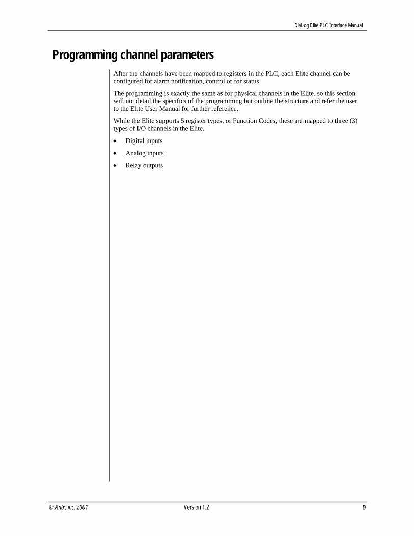
Programming channel parameters After the channels have been mapped to registers in the PLC, each Elite channel can be
configured for alarm notification, control or for status.
The programming is exactly the same as for physical channels in the Elite, so this section will not detail the specifics of the programming but outline the structure and refer the user to the Elite User Manual for further reference.
While the Elite supports 5 register types, or Function Codes, these are mapped to three (3) types of I/O channels in the Elite.
• Digital inputs
• Analog inputs
• Relay outputs
© Antx, inc. 2001 Version 1.2 9

DiaLog Elite PLC Interface Manual
Digital Inputs After entering the Register Type (Read Coil or Status) and Register Number the Elite drops down into the section that allows entering alarm and channel processing information.
n n. Channel Number [11-98]
0
Channel State
0 – Normally Open 1 – Normally Closed
1
Channel Messages
Alarm message (8 seconds) Normal message (8 seconds)
2
Channel Mode
0 – Disabled 1 – Status Only 2 – Call on Alarm 3 – Call on Limit
0 – Totalizer Limit [0-999,999,999 counts] (0) Scaling Value [1-1000] (1) Engineering Units [0-27] (0) 1 – Duration Limit [0-999,999,999 secs] (0) 2 – Limit Reset Period [0-999,999 mins] (0) 3 – Reset Counters on Acknowledge
0 – Disabled 1 – Enabled
3
Alarm Delay [0-65535 seconds] (3)
4
Continue alarm notification if return to normal
0 – Disabled 1 – Enabled
5
Telephone list [1-16] (1)
6
Relay channel to activate – [0-disabled, 11-98]
Relay state on Normal to Alarm is 0 – De-energized 1 – Energized 2 – Disabled
Relay state on Alarm to Normal is 0 – De-energized 1 – Energized 2 – Disabled
De-energize on alarm acknowledge 0 – Disabled 1 – Enabled
7
Channel Alphanumeric ID (CHAN nn)
. 10 Version 1.2 © Antx, inc. 2001

DiaLog Elite PLC Interface Manual
Analog Inputs After entering the Register Type (Holding or Input) and Register Number the Elite drops down into the section that allows entering alarm and channel processing information.
n n. Channel Number [11-98]
0
Channel Conversion
0
Decimal Position [0-5] (2) Zero Scale [0-99999] (0) Full Scale [0-99999] (10000) Zero Sign [ 0 – negative, 1 – positive]
1
0 disabled 1 milliamps 2 amps 3 volts 4 degrees Centigrade 5 degrees Fahrenheit 6 gallons 7 liters 8 pounds 9 kilograms 1 0 gallons per minute 1 1 gallons per hour 1 2 million gallons per hour 1 3 liters per hour 1 4 cubic inches per second 1 5 cubic feet per minute
1 6 cubic feet per hour 1 7 pounds per hour 1 8 feet per second 1 9 inches 2 0 feet 2 1 meters 2 2 parts per million 2 3 watts 2 4 kilowatts 2 5 degrees 2 6 pounds per square inch 2 7 percent 2 8 pH 2 9 Hz 3 0 kHz 3 1 mgal
2
Input Type [0-8]
0 0-1V 1 0-5V 2 1-5V
3 0-10V 4 0-20ma 5 4-20ma
6 +/- 1V 7 +/- 5V 8 +/- 10V
1
Channel Messages
Alarm message (8 seconds) Normal message (8 seconds)
2
Channel Mode
0 – Disabled 1 – Status Only 2 – Call on Alarm
© Antx, inc. 2001 Version 1.2 11
DiaLog Elite PLC Interface Manual
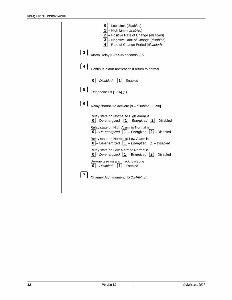
0 – Low Limit (disabled) 1 – High Limit (disabled) 2 – Positive Rate of Change (disabled) 3 – Negative Rate of Change (disabled) 4 – Rate of Change Period (disabled)
3
Alarm Delay [0-65535 seconds] (3)
4
Continue alarm notification if return to normal
0 – Disabled 1 – Enabled
5
Telephone list [1-16] (1)
6
Relay channel to activate [0 – disabled, 11-98]
Relay state on Normal to High Alarm is 0 – De-energized 1 – Energized 2 – Disabled
Relay state on High Alarm to Normal is 0 – De-energized 1 – Energized 2 – Disabled
Relay state on Normal to Low Alarm is 0 – De-energized 1 – Energized 2 – Disabled
Relay state on Low Alarm to Normal is 0 – De-energized 1 – Energized 2 – Disabled
De-energize on alarm acknowledge 0 – Disabled 1 – Enabled
7
Channel Alphanumeric ID (CHAN nn)
. 12 Version 1.2 © Antx, inc. 2001

DiaLog Elite PLC Interface Manual
Relay Outputs After entering the Register Type (Write Coil) and Register Number the Elite drops down into the section that allows entering alarm and channel processing information.
n n. Channel Number [11-98]
0
Pulse Duration [0-86400 seconds] (0)
2
Channel Mode
0 – Disabled 1 – Status Only
3
Channel Alphanumeric ID (CHAN nn)
4
Relay ID message
© Antx, inc. 2001 Version 1.2 13

DiaLog Elite PLC Interface Manual
. 14 Version 1.2 © Antx, inc. 2001

DiaLog Elite PLC Interface Manual
4 Running the Modbus Master Interface The Elite to PLC/Modbus communication starts for the first time when the Elite is put into
RUN mode after programming at least one channel for PLC/Modbus I/O.
The communication will continue running in RUN or PROGramming mode. The communication stops when changing parameters relating to the PLC setup – MODBUS PLC Setup and changing any of the Register Type or Register Numbers.
The display shows the following when the PLC Interface is enabled and no channels are in alarm.
RUN MODE 09/22/01 16:12:44 View Prnt Alms
F1 F2 F3 F4
Viewing Alarms If there are any MODBUS PLC alarms the following display is presented.
RUN MODE 09/22/01 16:12:44Alarms Pending… View Prnt Alms
F1 F2 F3 F4
This text blinks
To view the specific alarms, press the F3 key.
The following display will identify the channels in alarm.
© Antx, inc. 2001 Version 1.2 15

DiaLog Elite PLC Interface Manual
Modbus Comm. Failure Alarm
06 Communication Op Al Exit Scrl
F1 F2 F3 F4
Channel in alarm Op – Open – Loss of communication Al - Alarm
The Modbus Communication Failure Alarm can be caused by:
• incorrect physical connection • incorrect Modbus ID • incorrect mapping of Elite I/O to PLC I/O – i.e. the PLC is not responding to the
request to read/write the specific registers programmed
I/O channel alarm
71 Your channel name Op Al Exit Scrl
F1 F2 F3 F4
Channel in alarm Op – Open – current condition Al - Alarm
If an I/O channel is in alarm the display will look like above. If more than one channel is in alarm you can press the F4 key to scroll through all channels automatically or press the F2 and F3 arrow keys to move through the list.
Confirming Modbus Slave Communication To confirm that the Elite is reading the proper PLC/Modbus I/O use the View option F1
from the RUN mode screen.
The following display is presented.
Display Chan Values Ch # [01-98]: Exit
F1 F2 F3 F4
. 16 Version 1.2 © Antx, inc. 2001
DiaLog Elite PLC Interface Manual
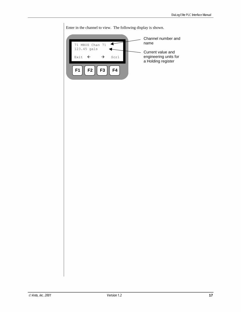
Enter in the channel to view. The following display is shown.
71 MBUS Chan 71 123.45 gals Exit Scrl
F1 F2 F3 F4
Channel number and name Current value and engineering units for a Holding register
© Antx, inc. 2001 Version 1.2 17

DiaLog Elite User Manual
© 2000 Antx, inc. 18 Version 1.2