Embed Size (px)
Citation preview
Dialing Plans ReferenceAvaya Communication Server 1000
Release 7.6NN43001-283
Issue 06.01March 2013

© 2013 Avaya Inc.
All Rights Reserved.
Notice
While reasonable efforts have been made to ensure that theinformation in this document is complete and accurate at the time ofprinting, Avaya assumes no liability for any errors. Avaya reserves theright to make changes and corrections to the information in thisdocument without the obligation to notify any person or organization ofsuch changes.
Documentation disclaimer
“Documentation” means information published by Avaya in varyingmediums which may include product information, operating instructionsand performance specifications that Avaya generally makes availableto users of its products. Documentation does not include marketingmaterials. Avaya shall not be responsible for any modifications,additions, or deletions to the original published version ofdocumentation unless such modifications, additions, or deletions wereperformed by Avaya. End User agrees to indemnify and hold harmlessAvaya, Avaya's agents, servants and employees against all claims,lawsuits, demands and judgments arising out of, or in connection with,subsequent modifications, additions or deletions to this documentation,to the extent made by End User.
Link disclaimer
Avaya is not responsible for the contents or reliability of any linkedwebsites referenced within this site or documentation provided byAvaya. Avaya is not responsible for the accuracy of any information,statement or content provided on these sites and does not necessarilyendorse the products, services, or information described or offeredwithin them. Avaya does not guarantee that these links will work all thetime and has no control over the availability of the linked pages.
Warranty
Avaya provides a limited warranty on its hardware and Software(“Product(s)”). Refer to your sales agreement to establish the terms ofthe limited warranty. In addition, Avaya’s standard warranty language,as well as information regarding support for this Product while underwarranty is available to Avaya customers and other parties through theAvaya Support website: http://support.avaya.com. Please note that ifyou acquired the Product(s) from an authorized Avaya reseller outsideof the United States and Canada, the warranty is provided to you bysaid Avaya reseller and not by Avaya. “Software” means computerprograms in object code, provided by Avaya or an Avaya ChannelPartner, whether as stand-alone products or pre-installed on hardwareproducts, and any upgrades, updates, bug fixes, or modified versions.
Licenses
THE SOFTWARE LICENSE TERMS AVAILABLE ON THE AVAYAWEBSITE, HTTP://SUPPORT.AVAYA.COM/LICENSEINFO AREAPPLICABLE TO ANYONE WHO DOWNLOADS, USES AND/ORINSTALLS AVAYA SOFTWARE, PURCHASED FROM AVAYA INC.,ANY AVAYA AFFILIATE, OR AN AUTHORIZED AVAYA RESELLER(AS APPLICABLE) UNDER A COMMERCIAL AGREEMENT WITHAVAYA OR AN AUTHORIZED AVAYA RESELLER. UNLESSOTHERWISE AGREED TO BY AVAYA IN WRITING, AVAYA DOESNOT EXTEND THIS LICENSE IF THE SOFTWARE WAS OBTAINEDFROM ANYONE OTHER THAN AVAYA, AN AVAYA AFFILIATE OR ANAVAYA AUTHORIZED RESELLER; AVAYA RESERVES THE RIGHTTO TAKE LEGAL ACTION AGAINST YOU AND ANYONE ELSEUSING OR SELLING THE SOFTWARE WITHOUT A LICENSE. BYINSTALLING, DOWNLOADING OR USING THE SOFTWARE, ORAUTHORIZING OTHERS TO DO SO, YOU, ON BEHALF OFYOURSELF AND THE ENTITY FOR WHOM YOU ARE INSTALLING,DOWNLOADING OR USING THE SOFTWARE (HEREINAFTERREFERRED TO INTERCHANGEABLY AS “YOU” AND “END USER”),AGREE TO THESE TERMS AND CONDITIONS AND CREATE ABINDING CONTRACT BETWEEN YOU AND AVAYA INC. OR THEAPPLICABLE AVAYA AFFILIATE (“AVAYA”).
Heritage Nortel Software
“Heritage Nortel Software” means the software that was acquired byAvaya as part of its purchase of the Nortel Enterprise SolutionsBusiness in December 2009. The Heritage Nortel Software currentlyavailable for license from Avaya is the software contained within the listof Heritage Nortel Products located at http://support.avaya.com/LicenseInfo under the link “Heritage Nortel Products”. For HeritageNortel Software, Avaya grants Customer a license to use HeritageNortel Software provided hereunder solely to the extent of theauthorized activation or authorized usage level, solely for the purposespecified in the Documentation, and solely as embedded in, forexecution on, or (in the event the applicable Documentation permitsinstallation on non-Avaya equipment) for communication with Avayaequipment. Charges for Heritage Nortel Software may be based onextent of activation or use authorized as specified in an order or invoice.
Copyright
Except where expressly stated otherwise, no use should be made ofmaterials on this site, the Documentation, Software, or hardwareprovided by Avaya. All content on this site, the documentation and theProduct provided by Avaya including the selection, arrangement anddesign of the content is owned either by Avaya or its licensors and isprotected by copyright and other intellectual property laws including thesui generis rights relating to the protection of databases. You may notmodify, copy, reproduce, republish, upload, post, transmit or distributein any way any content, in whole or in part, including any code andsoftware unless expressly authorized by Avaya. Unauthorizedreproduction, transmission, dissemination, storage, and or use withoutthe express written consent of Avaya can be a criminal, as well as acivil offense under the applicable law.
Third Party Components
“Third Party Components” mean certain software programs or portionsthereof included in the Software that may contain software (includingopen source software) distributed under third party agreements (“ThirdParty Components”), which contain terms regarding the rights to usecertain portions of the Software (“Third Party Terms”). Informationregarding distributed Linux OS source code (for those Products thathave distributed Linux OS source code) and identifying the copyrightholders of the Third Party Components and the Third Party Terms thatapply is available in the Documentation or on Avaya’s website at: http://support.avaya.com/Copyright. You agree to the Third Party Terms forany such Third Party Components.
Note to Service Provider
The Product may use Third Party Components that have Third PartyTerms that do not allow hosting and may need to be independentlylicensed for such purpose.
Preventing Toll Fraud
“Toll Fraud” is the unauthorized use of your telecommunications systemby an unauthorized party (for example, a person who is not a corporateemployee, agent, subcontractor, or is not working on your company'sbehalf). Be aware that there can be a risk of Toll Fraud associated withyour system and that, if Toll Fraud occurs, it can result in substantialadditional charges for your telecommunications services.
Avaya Toll Fraud intervention
If you suspect that you are being victimized by Toll Fraud and you needtechnical assistance or support, call Technical Service Center TollFraud Intervention Hotline at +1-800-643-2353 for the United Statesand Canada. For additional support telephone numbers, see the AvayaSupport website: http://support.avaya.com. Suspected securityvulnerabilities with Avaya products should be reported to Avaya bysending mail to: [email protected].
Trademarks
The trademarks, logos and service marks (“Marks”) displayed in thissite, the Documentation and Product(s) provided by Avaya are theregistered or unregistered Marks of Avaya, its affiliates, or other third
2 Dialing Plans Reference March 2013Comments? [email protected]
parties. Users are not permitted to use such Marks without prior writtenconsent from Avaya or such third party which may own the Mark.Nothing contained in this site, the Documentation and Product(s)should be construed as granting, by implication, estoppel, or otherwise,any license or right in and to the Marks without the express writtenpermission of Avaya or the applicable third party.
Avaya is a registered trademark of Avaya Inc.
All non-Avaya trademarks are the property of their respective owners,and “Linux” is a registered trademark of Linus Torvalds.
Downloading Documentation
For the most current versions of Documentation, see the AvayaSupport website: http://support.avaya.com.
Contact Avaya Support
See the Avaya Support website: http://support.avaya.com for productnotices and articles, or to report a problem with your Avaya product.For a list of support telephone numbers and contact addresses, go tothe Avaya Support website: http://support.avaya.com, scroll to thebottom of the page, and select Contact Avaya Support.
Dialing Plans Reference March 2013 3

4 Dialing Plans Reference March 2013Comments? [email protected]

Contents
Chapter 1: New in this release........................................................................................... 13Features.................................................................................................................................................... 13Other changes........................................................................................................................................... 13Revision history......................................................................................................................................... 13
Chapter 2: Customer service............................................................................................. 15Navigation................................................................................................................................................. 15Getting technical documentation............................................................................................................... 15Getting product training............................................................................................................................. 15Getting help from a distributor or reseller.................................................................................................. 15Getting technical support from the Avaya Web site.................................................................................. 16
Chapter 3: Introduction...................................................................................................... 17Navigation................................................................................................................................................. 17Subject...................................................................................................................................................... 17Note on legacy products and releases...................................................................................................... 17Applicable systems................................................................................................................................... 18System migration...................................................................................................................................... 18Intended audience.................................................................................................................................... 18Conventions.............................................................................................................................................. 19
Terminology...................................................................................................................................... 19Related information................................................................................................................................... 19
Technical documentation.................................................................................................................. 19Online............................................................................................................................................... 19
Chapter 4: Coordinated Dialing Plan description............................................................ 21Navigation................................................................................................................................................. 21Introduction............................................................................................................................................... 21Required packages................................................................................................................................... 22Steering codes.......................................................................................................................................... 22Conventional switch access...................................................................................................................... 24Network Class of Service.......................................................................................................................... 25Compatibility with ETN switches............................................................................................................... 26Assumptions.............................................................................................................................................. 27Facility Restriction Level........................................................................................................................... 27Example.................................................................................................................................................... 27Routing...................................................................................................................................................... 27Digit manipulation...................................................................................................................................... 28Time-of-day schedules.............................................................................................................................. 28Queuing..................................................................................................................................................... 28CDP traffic measurements........................................................................................................................ 29Feature interactions.................................................................................................................................. 29
AIOD and ANI................................................................................................................................... 29Attendant features............................................................................................................................ 29BARS/NARS..................................................................................................................................... 30Call modification............................................................................................................................... 30Call Detail Recording........................................................................................................................ 30
Dialing Plans Reference March 2013 5
Code Restriction............................................................................................................................... 30Collect Call Blocking......................................................................................................................... 31Common Control Switching Arrangement........................................................................................ 31COS/TGAR Treatment..................................................................................................................... 31Direct Inward Dialing........................................................................................................................ 32Display.............................................................................................................................................. 32End-to-End Signaling....................................................................................................................... 32Hunting............................................................................................................................................. 32Interchangeable Numbering Plan Area codes.................................................................................. 32Message Center............................................................................................................................... 33
Federal Communication Commission Equal Access Carrier Access Code Expansion impact................. 33Dialing Plan considerations.............................................................................................................. 33Carrier Access Codes dialing sequences with special characters................................................... 34Configuring Equal Access within a network..................................................................................... 35
Chapter 5: Flexible Numbering Plan description............................................................. 37Navigation................................................................................................................................................. 37Introduction............................................................................................................................................... 37Required packages................................................................................................................................... 38On-net dialing............................................................................................................................................ 38Off-net dialing............................................................................................................................................ 39
Chapter 6: Flexible Numbering Plan operation................................................................ 41Navigation................................................................................................................................................. 41On-net dialing............................................................................................................................................ 41
Location Code (LOC)....................................................................................................................... 41End-of-dial timing............................................................................................................................. 42Coordinated Dialing Plan.................................................................................................................. 42End-of-dial timing............................................................................................................................. 44Universal Numbering Plan................................................................................................................ 44Group dialing plan............................................................................................................................ 49
Digit display with Integrated Services Digital Network.............................................................................. 50LOC+DN dialing............................................................................................................................... 51CDP dialing...................................................................................................................................... 51Group dialing.................................................................................................................................... 51
Off-net dialing............................................................................................................................................ 53Special Numbers (SPN)................................................................................................................... 53FLEN set to 0................................................................................................................................... 55FLEN is nonzero............................................................................................................................... 55End-of-dial timing............................................................................................................................. 57Numbering Plan Area (NPA) and NXX............................................................................................. 57End-of-dial timing............................................................................................................................. 59
Vacant Number Routing............................................................................................................................ 60Free Calling Area Screening..................................................................................................................... 60Free Special Number Screening............................................................................................................... 60Capacity expansion................................................................................................................................... 61
RLB and DMl expansion................................................................................................................... 61LOC, LSC, DSC TSC expansion...................................................................................................... 61AC1 and AC2 expansion.................................................................................................................. 61
6 Dialing Plans Reference March 2013
Feature interactions.................................................................................................................................. 62Digital Access Signaling System 2 and Digital Private Network Signaling System 1....................... 62Directory Number (DN) entries......................................................................................................... 62ESN feature interactions.................................................................................................................. 62Group Dialing Plan........................................................................................................................... 62Integrated Services Digital Network................................................................................................. 62Vacant Number Routing................................................................................................................... 63Supplemental Digit Restriction or Recognition................................................................................. 63Transferable DNs............................................................................................................................. 63Varying length DNs........................................................................................................................... 63
Chapter 7: Feature Group D description........................................................................... 65Navigation................................................................................................................................................. 65Introduction............................................................................................................................................... 65
Required packages.......................................................................................................................... 66Local network and end office switching..................................................................................................... 67Originating features................................................................................................................................... 68
Domestic dialing plan....................................................................................................................... 68Pre-subscription............................................................................................................................... 69Service Access Code....................................................................................................................... 69Ancillary Carrier identification (10-digit translation).......................................................................... 69Embodied Carrier identification (6 - digit translation)....................................................................... 69External Carrier identification........................................................................................................... 69Automatic Number Identification (ANI)............................................................................................. 70Signaling protocol............................................................................................................................. 70Carrier test lines............................................................................................................................... 70Outpulsing........................................................................................................................................ 70
Terminating features.................................................................................................................................. 70LEC test lines................................................................................................................................... 70
Interface protocol...................................................................................................................................... 71Direction........................................................................................................................................... 71Signaling protocol............................................................................................................................. 71Terminating protocol......................................................................................................................... 71Exchange Access North American (EANA) signaling...................................................................... 72Carrier classification......................................................................................................................... 73Call categories and pulsing formats................................................................................................. 73
EANA protocol specifications.................................................................................................................... 75LEC-to-carrier pulsing...................................................................................................................... 75Variations.......................................................................................................................................... 75Alternative arrangements................................................................................................................. 76Time limits........................................................................................................................................ 76EANA protocol example................................................................................................................... 77Terminating protocol example.......................................................................................................... 77
Hardware................................................................................................................................................... 78Trunks............................................................................................................................................... 78MF signaling..................................................................................................................................... 78MF senders...................................................................................................................................... 78MF receivers..................................................................................................................................... 79
Dialing Plans Reference March 2013 7
General description.......................................................................................................................... 79Feature interactions.................................................................................................................................. 81
Access restriction............................................................................................................................. 81Automatic Trunk Maintenance (ATM)............................................................................................... 84Barge-In............................................................................................................................................ 85Call Detail Recording (CDR)............................................................................................................ 85Calling Line ID (CLID)...................................................................................................................... 85Call Party Disconnect Control (CPDC)............................................................................................. 85Call Party Name Display (CPND)..................................................................................................... 85Customer Controlled Routing (CCR)................................................................................................ 85Dialed Number Identification Service (DNIS)................................................................................... 86Digit Display..................................................................................................................................... 86Incoming Digit Conversion (IDC)...................................................................................................... 86ISDN PRI and ISL............................................................................................................................ 86Network Alternate Route Selection (NARS)..................................................................................... 87Network Call Redirection (NCRD).................................................................................................... 87Malicious Call Trace (MCT).............................................................................................................. 87Minor Alarm...................................................................................................................................... 87Private Line Service......................................................................................................................... 87Traffic measurements....................................................................................................................... 88Trunk Group Distinctive Ringing....................................................................................................... 88Trunk Verification from a Station (TVS)............................................................................................ 88
Chapter 8: Feature Group D operation.............................................................................. 91Navigation................................................................................................................................................. 91Example: Using Feature Group D............................................................................................................. 91
How to initiate a call......................................................................................................................... 91Incoming call processing........................................................................................................................... 92
Local termination.............................................................................................................................. 93Calls inside World Zone 1 (7 digits).................................................................................................. 93Calls inside World Zone 1 (10 digits)................................................................................................ 93Calls inside World Zone 1 (0+ and 0-).............................................................................................. 94Information digits screening for incoming calls................................................................................. 95FGD call intercept............................................................................................................................. 96Incoming test calls (3 and 7 digits)................................................................................................... 96Authorization Code prompting.......................................................................................................... 97LEC trunk grouping and ANI provision by call category................................................................... 97
Dial pulse dialing on FGD trunks............................................................................................................... 101Outgoing test calls............................................................................................................................ 101CDR records..................................................................................................................................... 101Transmission characteristics............................................................................................................ 101
Operating parameters............................................................................................................................... 102Parameters....................................................................................................................................... 102MF Receiver guidelines.................................................................................................................... 102
Chapter 9: Feature Group D implementation................................................................... 107Navigation................................................................................................................................................. 107Engineering guidelines.............................................................................................................................. 107
LD 21 : Print routine......................................................................................................................... 113
8 Dialing Plans Reference March 2013

LD 22 : Print routine......................................................................................................................... 113Chapter 10: Feature Group D maintenance and diagnostics.......................................... 115
Navigation................................................................................................................................................. 115Introduction............................................................................................................................................... 115LD 34 : Tone and digital switch................................................................................................................. 115
Command description...................................................................................................................... 116LD 30 : Network and signaling diagnostics............................................................................................... 117LD 32 : Network peripheral equipment diagnostics.................................................................................. 117
Chapter 11: Flexible Numbering Plan administration...................................................... 119Navigation................................................................................................................................................. 119Introduction............................................................................................................................................... 119Electronic Switched Network (ESN) data.................................................................................................. 120Electronic Switched Network 2 (ESN2) data............................................................................................. 121Electronic Switched Network (ESN) translation tables............................................................................. 124Customer data block configuration........................................................................................................... 127Flexible Numbering Plan configuration..................................................................................................... 129
Chapter 12: Zone Based Dialing plan configuration........................................................ 131Navigation................................................................................................................................................. 131Introduction............................................................................................................................................... 131
High level tasks for configuring ZBD................................................................................................ 133Required packages.......................................................................................................................... 133Limitations........................................................................................................................................ 133Migration planning............................................................................................................................ 134Deployment options.......................................................................................................................... 135Private Numbering Plan (CDP/UDP)................................................................................................ 135Public E.164 numbering and Dial Plan............................................................................................. 136Dial Plan considerations................................................................................................................... 136
Element Manager...................................................................................................................................... 137Numbering Zone configuration in Element Manager........................................................................ 137Enabling Numbering Zone................................................................................................................ 137Adding a new Numbering Zone........................................................................................................ 138Looking up the Country Code........................................................................................................... 141Editing the Numbering Zones Data.................................................................................................. 142Adding a New Dialing configuration................................................................................................. 143Configuring the Flexible Dial Plan.................................................................................................... 144Configuring the Direct Inward Dial number...................................................................................... 145
Phones configuration in Element Manager............................................................................................... 146Retrieving a phone with NUMZONE configuration........................................................................... 147Adding a Phone with NUMZONE configuration................................................................................ 147Copying from TN.............................................................................................................................. 148Adding a phone using a template..................................................................................................... 149Editing Phone Details for Numbering Zone supported Phones........................................................ 149Performing Bulk Phone edit.............................................................................................................. 150Generating an HTML or CSV report................................................................................................. 150Moving a phone with Numbering Zone configuration....................................................................... 152Swapping a phone with Numbering Zone configuration................................................................... 152Enabling the Numbering Zone option on a phone............................................................................ 153
Dialing Plans Reference March 2013 9

Disabling the Numbering Zone option for unsupported phones (VOLO).......................................... 153Adding a phone with NUMZONE configured through Communication Server 1000 CLI................. 153Editing a phone with NUMZONE configured through Avaya CS1000 CLI....................................... 154Deleting a phone with NUMZONE configured through CS1000 CLI................................................ 154
E.164 dial plan configuration..................................................................................................................... 155Introduction....................................................................................................................................... 155AC1 and AC2 tables......................................................................................................................... 155INAC................................................................................................................................................. 157E.164 International format in dial plan configurations...................................................................... 157Basic dial plan configuration concepts............................................................................................. 157E.164 configuration for calls in the same call server........................................................................ 159E.164 configuration for calls to different call servers........................................................................ 161PSTN calls........................................................................................................................................ 163For routing within the same call server............................................................................................. 164For routing to a different call server.................................................................................................. 164Further processing of PSTN calls: sending PSTN calls over local PRI trunks................................. 165Further processing of PSTN calls –– sending to local GW to PSTN................................................ 166ESA calls.......................................................................................................................................... 170E.164 enhancements for Office Communications Server 2007........................................................ 172Outgoing SIP CTI call from IP phone to on-net E.164 number using IP WAN................................. 172On-net dialing with abbreviated E.164 numbers.............................................................................. 173ZFDP configuration.......................................................................................................................... 176E.164 dial plan.................................................................................................................................. 177ZFDP configuration for E.164 — North America.............................................................................. 178ZFDP configuration for E.164 — Europe.......................................................................................... 178SPN.................................................................................................................................................. 179ZFDP configuration for SPN............................................................................................................. 179ZFDP ESDN for ESA calls............................................................................................................... 180ZFDP configuration for ESDN.......................................................................................................... 180Alternate Call Routing...................................................................................................................... 180Insufficient bandwidth....................................................................................................................... 181Unregistered resources.................................................................................................................... 181LD 117.............................................................................................................................................. 182MO-BO model.................................................................................................................................. 182Call Forward No Answer (CFNA) configuration................................................................................ 186
Local Dialing.............................................................................................................................................. 187Private dialing............................................................................................................................................ 189
On-net dialing with Private numbers within same call server........................................................... 189On-Net Dialing with Private Numbers across different Call Servers................................................. 191Outgoing OC client SIP Gateway call to on-net Private number using IP WAN............................... 194
Call Flow for Local Dialing......................................................................................................................... 195Call Flow for emergency dialing with SBO................................................................................................ 198Call Flow for emergency dialing with SMG............................................................................................... 200Initial DN key download for Local DN (3-5 digits)..................................................................................... 202Call flow for Private Number dialing during WAN outage.......................................................................... 203LD Tables.................................................................................................................................................. 206
LD 15: Configure zone based parameters for ZBD option............................................................... 207
10 Dialing Plans Reference March 2013

LD 117: Configure numbering zone and numbering zone based parameters.................................. 207LD 10 and LD 11: Configure a telephone with numbering zone....................................................... 208LD 12: Store numbering zone for an attendant................................................................................ 208LD 81: Print a list or count of telephones with selected numbering zone......................................... 209
Diagnostic logs.......................................................................................................................................... 209Index..................................................................................................................................... 211
Dialing Plans Reference March 2013 11

12 Dialing Plans Reference March 2013

Chapter 1: New in this release
The following sections detail what is new in Dialing Plans Reference, NN43001-283 for AvayaCommunication Server 1000 Release 7.5.
• Features on page 13• Other changes on page 13
FeaturesThere are no updates to the feature descriptions in this document for Communication Server1000 Release 7.6.
Other changesThis section describes other changes for Release 7.6.
Revision history
March 2013 Standard 06.01. This document is up-issued to support AvayaCommunication Server 1000 Release 7.6.
November 2010 Standard 05.02. This document is issued to support AvayaCommunication Server 1000 Release 7.5.
November 2010 Standard 05.01. This document is issued for Avaya CommunicationServer 1000 Release 7.5.
July 2010 Standard 04.02. This document is up-issued for AvayaCommunication Server 1000 Release 7.0. Change made to theAlternate Call Routing section relating to VPNI configuration.
June 2010 Standard 04.01. This document is up-issued for AvayaCommunication Server 1000 Release 7.0.
June 2009 Standard 03.09. This document is up-issued to supportCommunication Server 1000 Release 6.0.
Dialing Plans Reference March 2013 13

June 2009 Standard 03.08. This document is up-issued to supportCommunication Server 1000 Release 6.0.
May 2009 Standard 03.07. This document is up-issued to supportCommunication Server 1000 Release 6.0.
May 2009 Standard 03.06. This document is up-issued to supportCommunication Server 1000 Release 6.0.
May 2009 Standard 03.05. This document is up-issued to supportCommunication Server 1000 Release 6.0.
May 2009 Standard 03.04. This document is up-issued to supportCommunication Server 1000 Release 6.0.
April 2009 Standard 03.03. This document is up-issued to supportCommunication Server 1000 Release 6.0.
April 2009 Standard 03.02. This document is up-issued to supportCommunication Server 1000 Release 6.0.
December 2007 Standard 02.01. This document is up-issued to supportCommunication Server 1000 Release 5.5.
June 2007 Standard 01.02. Up-issued to remove the confidentialitystatement.
May 2007 Standard 01.01. This document is issued to support CommunicationServer 1000 Release 5.0.This document contains information previously in the followingdocument, now retired:Dialing Plans: Description, 553-3001-183.No new content exists for Communication Server Release 5.0. Allreferences to Communication Server Release 4.5 are apply toCommunication Server 1000 Release 5.0.
November 2006 Standard 4.0. Up-issued to support changes in content.
August 2005 Standard 3.00. Up-issued to support Communication Server 1000Release 4.5.
September 2004 Standard 2.00. Up-issued to support Communication Server 1000Release 4.0.
October 2003 Standard 1.00. This document is new for Succession 3.0. It wascreated to support a restructuring of the Documentation Library,which resulted in the merging of multiple legacy documents.This document consolidates information previously in the followingdocuments, now retired:
• Coordinated Dialing Plan, (553-2751-102)
• Flexible Numbering Plan, (553-2751-105)
• Feature Group D, (553-2901-102)
New in this release
14 Dialing Plans Reference March 2013Comments? [email protected]
Chapter 2: Customer service
Visit the Avaya Web site to access the complete range of services and support that Avaya provides. Goto www.avaya.com or go to one of the pages listed in the following sections.
Navigation• Getting technical documentation on page 15
• Getting product training on page 15
• Getting help from a distributor or reseller on page 15
• Getting technical support from the Avaya Web site on page 16
Getting technical documentationTo download and print selected technical publications and release notes directly from theInternet, go to www.avaya.com/support.
Getting product trainingOngoing product training is available. For more information or to register, go to www.avaya.com/support. From this Web site, locate the Training link on the left-handnavigation pane.
Getting help from a distributor or resellerIf you purchased a service contract for your Avaya product from a distributor or authorizedreseller, contact the technical support staff for that distributor or reseller for assistance.
Dialing Plans Reference March 2013 15
Getting technical support from the Avaya Web siteThe easiest and most effective way to get technical support for Avaya products is from theAvaya Technical Support Web site at www.avaya.com/support.
Customer service
16 Dialing Plans Reference March 2013Comments? [email protected]

Chapter 3: Introduction
This document is a global document. Contact your system supplier or your Avaya representative to verifythat the hardware and software described are supported in your area.
Navigation• Subject on page 17
• Note on legacy products and releases on page 17
• Applicable systems on page 18
• System migration on page 18
• Intended audience on page 18
• Conventions on page 19
• Related information on page 19
SubjectThis document includes description, operation, implementation, administration andmaintenance information about Coordinated Dialing Plan, Flexible Numbering Plan, FeatureGroup D, and Zone Based Dialing Plan.
Note on legacy products and releasesThis document contains information about systems, components, and features that arecompatible with Avaya Communication Server 1000 software. For more information aboutlegacy products and releases, click Technical Documentation, under Support on the Avayahome page:
www.avaya.com
Dialing Plans Reference March 2013 17
Applicable systemsThis document applies to the following systems:
• Communication Server 1000M Single Group (CS 1000M SG)• Communication Server 1000M Multi Group (CS 1000M MG)• Communication Server 1000E (CS 1000E)
System migrationWhen particular Meridian 1 systems are upgraded to run Communication Server 1000 Release6.0 software and configured to include a Signaling Server, they become Communication Server1000 systems. The following table lists each Meridian 1 system that supports an upgrade pathto a Communication Server 1000 system.
Table 1: Meridian 1 systems to CS 1000 systems
This Meridian 1 system Maps to Communication Server 1000 systemMeridian 1 PBX 11C Chassis Communication Server 1000E
Meridian 1 PBX 11C Cabinet Communication Server 1000E
Meridian 1 PBX 61C Communication Server 1000M Single Group
Meridian 1 PBX 81C Communication Server 1000M Multi Group
For more information, see Avaya Communication Server 1000M and Meridian 1 Large SystemUpgrades Overview, NN43021-458, Avaya Communication Server 1000E Upgrades,NN43041-458, and Avaya Communication Server 1000E Upgrade — Hardware UpgradeProcedures, NN43041-464.
Intended audienceThis document is intended for individuals responsible for administering Communication Server1000 and Meridian 1 systems.
Introduction
18 Dialing Plans Reference March 2013Comments? [email protected]

Conventions
TerminologyIn this document, the following systems are referred to generically as system:
• Communication Server 1000E (CS 1000E)• Communication Server 1000M (CS 1000M)• Meridian 1
Unless specifically stated otherwise, the term Element Manager refers to the CommunicationServer 1000 Element Manager.
Related informationThis section lists information sources that relate to this document.
Technical documentationThis document references the following technical documents:
• Features and Services Fundamentals, NN43001-106• Unified Communications Management Common Services Fundamentals, NN43001-116• IP Peer Networking Installation and Commissioning, NN43001-313• Linux Platform Base and Applications Installation and Commissioning, NN43001-315• Hospitality Features Fundamentals, NN43001-553• Software Input Output Administration, NN43001-611• Software Input Output Reference - Maintenance, NN43001-711• Software Input Output Reference - System Messages, NN43001-712
OnlineTo access Avaya documentation online, go to the Avaya home page:
Conventions
Dialing Plans Reference March 2013 19

Chapter 4: Coordinated Dialing Plandescription
Navigation• Introduction on page 21
• Steering codes on page 22
• Conventional switch access on page 24
• Network Class of Service on page 25
• Compatibility with ETN switches on page 26
• Routing on page 27
• Digit manipulation on page 28
• Time-of-day schedules on page 28
• Queuing on page 28
• CDP traffic measurements on page 29
• Feature interactions on page 29
• Federal Communication Commission Equal Access Carrier Access Code Expansionimpact on page 33
IntroductionThe Coordinated Dialing Plan (CDP) feature enables a customer with a system to coordinatethe dialing plan for stations at these switches.
When implemented, the CDP feature enables a station at one switch to call a station at anotherswitch within the CDP group by dialing a unique three to seven digit number, without accesscodes and associated pauses for dial tone. When equipped with the Directory Expansion(DNXP) package, this number can have up to ten digits.
CDP software provides the translation and digit manipulation capability required to implementthe CDP. Calls dialed with the CDP format can be terminated locally after digit translation ordigit deletion. Alternatively, calls can be routed to a remote switch in the CDP group following
Dialing Plans Reference March 2013 21

digit translation, route selection, and digit deletion or insertion. Figure 1: Example of aCoordinated Dialing Plan on page 23 illustrates how a coordinated dialing plan can beimplemented at two customer locations.
Required packagesCoordinated Dialing Plan (CDP), requires Directory Expansion (DNXP) package to enablestations at different switches within the CDP group to dial using a unique number up to 10digits.
Steering codesIn Figure 1: Example of a Coordinated Dialing Plan on page 23, end users at Location D cancall stations at Location E by dialing 43XXX or 52XXX. Similarly, end users at Location E cancall stations at Location D by dialing 2XXXX or 3XXXX. If an end user at Location D dials43XXX or 52XXX to reach a station at Location E, Location D uses the digits "43" or "52" as aDistant Steering Code (DSC) to select the trunk group to Location E. Similarly, if an end userat Location E dials 2XXXX or 3XXXX to reach a station at Location D, Location E uses the digit2 or 3 as a Distant Steering Code (DSC).
Coordinated Dialing Plan description
22 Dialing Plans Reference March 2013Comments? [email protected]
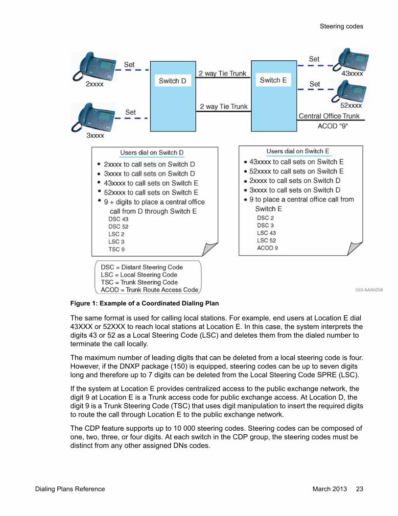
Figure 1: Example of a Coordinated Dialing Plan
The same format is used for calling local stations. For example, end users at Location E dial43XXX or 52XXX to reach local stations at Location E. In this case, the system interprets thedigits 43 or 52 as a Local Steering Code (LSC) and deletes them from the dialed number toterminate the call locally.
The maximum number of leading digits that can be deleted from a local steering code is four.However, if the DNXP package (150) is equipped, steering codes can be up to seven digitslong and therefore up to 7 digits can be deleted from the Local Steering Code SPRE (LSC).
If the system at Location E provides centralized access to the public exchange network, thedigit 9 at Location E is a Trunk access code for public exchange access. At Location D, thedigit 9 is a Trunk Steering Code (TSC) that uses digit manipulation to insert the required digitsto route the call through Location E to the public exchange network.
The CDP feature supports up to 10 000 steering codes. Steering codes can be composed ofone, two, three, or four digits. At each switch in the CDP group, the steering codes must bedistinct from any other assigned DNs codes.
Steering codes
Dialing Plans Reference March 2013 23

As Figure 1: Example of a Coordinated Dialing Plan on page 23 shows:
• 0 is reserved as the attendant access code
• 1 is reserved as the Special Service Prefix (SPRE)
• 7 is reserved as a system trunk access code
• 8 is reserved as a Basic Alternate Route Selection / Network Alternate Route Selection(BARS/NARS) access code
• 9 is reserved as the public exchange network access code
There are five digits that can be used as the leading digits of steering codes - 2, 3, 4, 5, and6. Switch D chooses 2 and 3; switch E uses 4 and 5.
A CDP Directory Number (DN) consists of an internal DN prefixed with the appropriate steeringcode. The CDP DN can support up to seven digits; but, if the DNXP package is equipped, theCDP DN can support up to ten digits. A typical CDP configuration is shown in Figure 2: A typicalCDP Configuration on page 24.
Figure 2: A typical CDP Configuration
Conventional switch accessIf a conventional (CONV) switch without the CDP software is integrated as part of a CDP group(see Figure 2: A typical CDP Configuration on page 24), the steering codes defined at a CDPswitch to access the conventional switch can be inserted or deleted by the CDP switch. Thesteering codes are inserted if the conventional switch is identified by more than one steering
Coordinated Dialing Plan description
24 Dialing Plans Reference March 2013Comments? [email protected]

code; they are deleted if all the station numbers at the conventional switch begin with the samesteering code.
Calls to a CDP switch from the conventional switch are made by dialing the desired CDP DN.The CONV switch uses the digit 6 as a trunk access code for the tie trunk route to switch CDP2.After tie trunk seizure, the CONV switch outpulses the remaining digits (7000) to CDP2. AtCDP2, the digit 6 is inserted on the incoming tie trunk from the CONV switch, prior to receiptof any digits from the CONV switch, and the call completes to station E.
Local calls at the CONV switch are made by dialing only the internal DN (3500), rather thanthe CDP DN (53500), unless the CONV switch can be arranged to absorb the digit 5 or is basedon a 5-digit numbering plan.
As shown in Figure 2: A typical CDP Configuration on page 24, switch CDP2 is arranged toprovide centralized access to the public exchange network. For end users at the CONV switchto access this capability, a separate tie trunk route must be provided to switch CDP2. This isbecause switch CDP2 is arranged to insert the digit "6" on the incoming tie trunk route fromthe CONV switch used for CDP calls. For public exchange network calls, the digit 9 must beinserted on the incoming tie trunk route from the CONV switch. Similarly, if end users at theCONV switch support access to the ESN capabilities (BARS/NARS) at switch CDP2, anothertie trunk route must be provided for this purpose.
Network Class of ServiceNetwork Class of Service (NCOS) is an integral part of the CDP feature. NCOS provides themeans to control the following:
• which trunk routes can be accessed to complete the CDP call
• whether or not queuing is offered to the call originator
• whether or not the originator of a CDP call receives an Expensive Route Warning Tone(ERWT) when an expensive trunk route is selected to complete the call
A switch equipped with CDP can accommodate four NCOS groups (0–3), each group withdifferent route-access characteristics. See Table 2: Summary of CDP parameters onpage 25.
Table 2: Summary of CDP parameters
ParameterCDP stand-
aloneCDP with
BARSCDP with
NARSNetwork Class of Service Groups* 0–3 (0–99) 0–7 (0–99) 0–15 (0–
99)
Facility Restriction Levels 0–7 0–7 0–7
Time-of-Day schedules 0–1 0–7 0–7
Network Class of Service
Dialing Plans Reference March 2013 25
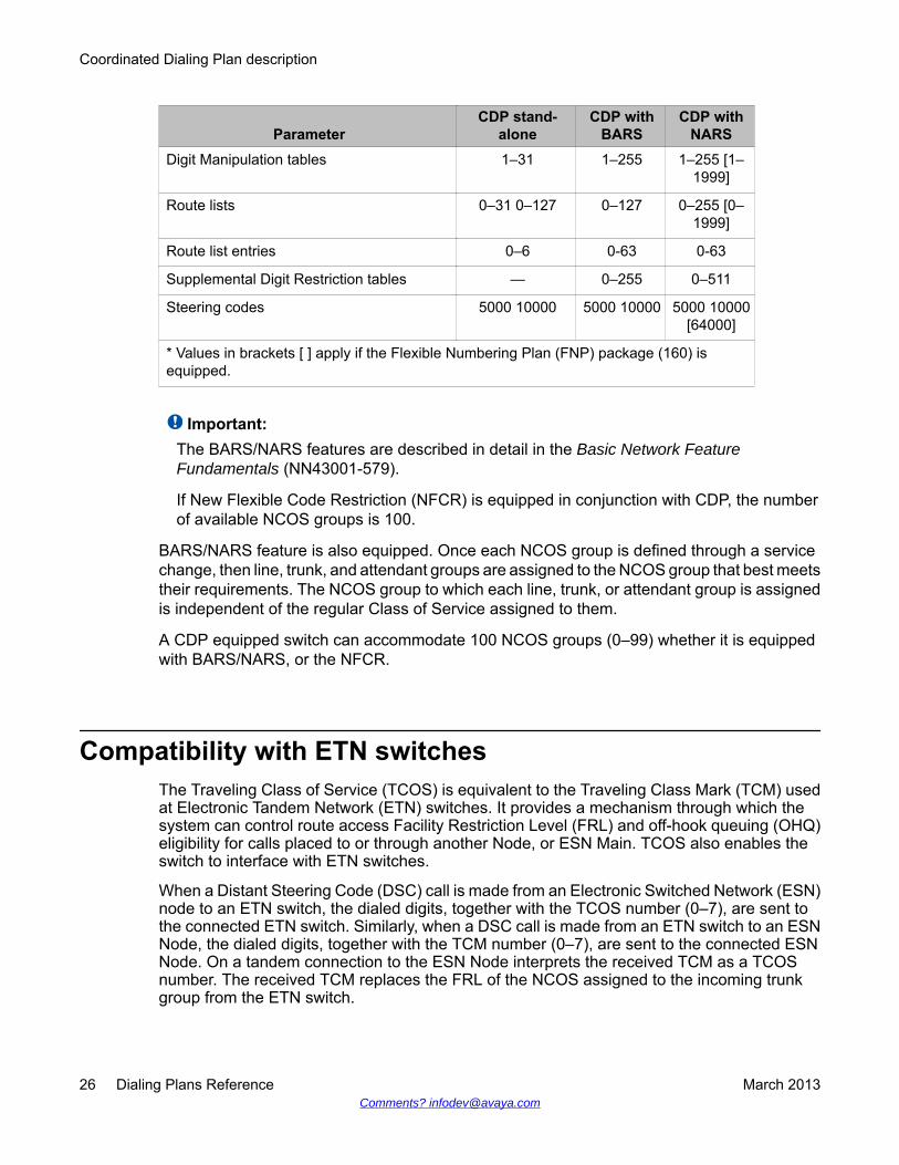
ParameterCDP stand-
aloneCDP with
BARSCDP with
NARSDigit Manipulation tables 1–31 1–255 1–255 [1–
1999]
Route lists 0–31 0–127 0–127 0–255 [0–1999]
Route list entries 0–6 0-63 0-63
Supplemental Digit Restriction tables — 0–255 0–511
Steering codes 5000 10000 5000 10000 5000 10000[64000]
* Values in brackets [ ] apply if the Flexible Numbering Plan (FNP) package (160) isequipped.
Important:The BARS/NARS features are described in detail in the Basic Network FeatureFundamentals (NN43001-579).
If New Flexible Code Restriction (NFCR) is equipped in conjunction with CDP, the numberof available NCOS groups is 100.
BARS/NARS feature is also equipped. Once each NCOS group is defined through a servicechange, then line, trunk, and attendant groups are assigned to the NCOS group that best meetstheir requirements. The NCOS group to which each line, trunk, or attendant group is assignedis independent of the regular Class of Service assigned to them.
A CDP equipped switch can accommodate 100 NCOS groups (0–99) whether it is equippedwith BARS/NARS, or the NFCR.
Compatibility with ETN switchesThe Traveling Class of Service (TCOS) is equivalent to the Traveling Class Mark (TCM) usedat Electronic Tandem Network (ETN) switches. It provides a mechanism through which thesystem can control route access Facility Restriction Level (FRL) and off-hook queuing (OHQ)eligibility for calls placed to or through another Node, or ESN Main. TCOS also enables theswitch to interface with ETN switches.
When a Distant Steering Code (DSC) call is made from an Electronic Switched Network (ESN)node to an ETN switch, the dialed digits, together with the TCOS number (0–7), are sent tothe connected ETN switch. Similarly, when a DSC call is made from an ETN switch to an ESNNode, the dialed digits, together with the TCM number (0–7), are sent to the connected ESNNode. On a tandem connection to the ESN Node interprets the received TCM as a TCOSnumber. The received TCM replaces the FRL of the NCOS assigned to the incoming trunkgroup from the ETN switch.
Coordinated Dialing Plan description
26 Dialing Plans Reference March 2013Comments? [email protected]

AssumptionsThe assumptions are as follows:
• Only DSC calls, not Trunk Steering Code (TSC) calls, are supported.
• When a DSC call is terminated on a switch as a Local Steering Code (LSC) call, thetransmitted TCOS/TCM number from the connected ETN switch is not collected andsaved by the terminating switch.
Facility Restriction LevelIncluded as part of each NCOS group is a Facility Restriction Level (FRL) number that rangesfrom 0 (low-privilege) to 7 (high-privilege). CDP software uses the FRL to determine thealternate route selection choices available for CDP call attempts by end users within an NCOSgroup.
ExampleA station user assigned in an NCOS group with an FRL of 3 can only access alternate routeselection choices with an FRL of 3 or less: that is, access to trunks with an FRL greater than3 is denied.
RoutingThirty-two route lists (0–31) can be defined at a switch equipped with CDP. See Table 2:Summary of CDP parameters on page 25 for other parameters if CDP is equipped with BARSor NARS. A route list is used to define the alternate route choices for CDP calls to a particulardestination. Route choices in a route list are called route list entries. There can be up to seven(0–6) route list entries associated with each route list.
Route lists are associated with each Distant Steering Code (DSC) and Trunk Steering Code(TSC) that can be dialed at a CDP switch. Local Steering Codes (LSC) are not associated withroute lists. Each code is defined to the CDP software, together with the route list number thatmust be accessed for call completion to the destination indicated by the steering code. Theentries in the specified route list are then searched sequentially for an available and eligibletrunk route.
Assumptions
Dialing Plans Reference March 2013 27
Software enables CDP to route Direct Inward Dialed (DID) calls over CO and WATS trunksusing a DSC. The feature is controlled by an option defined in the Customer Data Block (LD15) found in Software Input/Output Administration, NN43001-611. This enhancement appliesto CO, WATS, DTI and ISDN type trunks.
Digit manipulationRoute list entries can be associated with digit manipulation tables. There can be 32 (0–31)digit manipulation tables defined at a CDP switch. See Table 2: Summary of CDPparameters on page 25 if BARS/NARS is also equipped. Every digit manipulation table except0 can be defined to delete up to 15-digits from a dialed CDP number, and to insert up to 24leading digits, including the asterisk. Digit manipulation table 0 is used as an indication to theCDP software that no digit manipulation is required. You can also insert the character P toinsert zone prefix.
The C character can be inserted to represent the country code of the terminating TN. Usingthe p and c characters in the digit manipulation tables, reduces the number of DMI entriesrequired and the complexity of configurations if the Survivable Media Gateways are located indifferent countries. For an example, see Call flow for Private Number dialing during WANoutage on page 203.
Time-of-day schedulesTwo (0–1) time-of-day (TOD) schedules can be defined at a CDP switch. See Table 2:Summary of CDP parameters on page 25 if BARS/NARS is also equipped. Each route list entryis associated with a TOD schedule. When a route list entry is selected for a CDP call, the CDPsoftware compares the current time with the TOD schedule assigned to the route list entry. Ifthe current time is within the schedule, the route list entry is used for the call. If the current timeis not in the schedule or if the TOD schedule is turned OFF, the route list entry is not used forthe call. Each TOD schedule can be turned ON or OFF by the customer through servicechange.
QueuingQueuing against local stations is provided by the standard Ring Again (RGA) feature. Refer toFeatures and Services Fundamentals (NN43001-106). For calls directed to a remote CDPswitch, Ring Again can be applied if all local outgoing trunk routes to the remote CDP switchare busy or blocked. Ring Again cannot be applied against busy or blocked telephones, orconsoles at the remote CDP switch. Ring Again is only available on trunks if CCBQ or CBQM
Coordinated Dialing Plan description
28 Dialing Plans Reference March 2013Comments? [email protected]
are equipped. Intercept treatment is not provided until the full CDP number (or trunk steeringcode) is dialed.
For local and network queuing descriptions, refer to Basic Network Feature Fundamentals(NN43001-579). For ESN operations in an ISDN environment, refer to ISDN Primary RateInterface Features Fundamentals (NN43001-569).
CDP traffic measurementsTraffic measurement data related to CDP feature usage is available on a system equipped withthe Network Traffic (NTRF) feature. Refer to Traffic Measurement Formats and OutputsReference (NN43001-750).
Feature interactions
AIOD and ANICalls made to the public exchange network when the Automatic Identification of OutwardDialing (AIOD) or Automatic Number Identification (ANI) feature is equipped have either theinternal DN recorded if the call originates at the CDP switch interfacing to the public networkor the trunk access code if the call originates at another CDP switch.
Attendant featuresIf a user at a local CDP switch calls the local attendant, the local user's internal DN (not thefull CDP DN) displays. If a user at a CDP switch calls an attendant at another CDP switch, thetrunk access code and member number are part of the incoming trunk display.
The following attendant features are supported at a local CDP switch but are not supportedbetween CDP switches:
• automatic timed recall
• barge-in, busy verify
• camp-on
• interposition calling
CDP traffic measurements
Dialing Plans Reference March 2013 29
BARS/NARSThe CDP feature can be implemented at a switch equipped with the BARS/NARS softwarefeatures. If this is the case, the following considerations apply:
• Steering codes for CDP calls must be distinct from the assigned BARS/NARS accesscodes.
• CDP numbers can be integrated with the NARS Uniform Dialing Plan (UDP). For example,a five-digit CDP number can be the same as the last five digits of a seven-digit UDPnumber.
• BARS/NARS route lists, digit manipulation tables and TOD schedules can be shared byCDP calls.
• Users eligible for the Off-Hook Queuing (OHQ) and Call-Back Queuing (CBQ) featurescan use them when placing CDP calls.
• Free Calling Area Screening (FCAS) does not apply to CDP calls.
• Routing Control can be applied to CDP calls. Refer to Basic Network FeatureFundamentals (NN43001-579).
Call modificationCall modification (call transfer, call forward, conference) is enabled for CDP calls. When usingthese features, the end user dials within the CDP format.
Call Detail RecordingThe local internal DN (not the complete CDP DN) is recorded in the normal Call DetailRecording (CDR) manner. The full CDP DN is shown in the dialed number field. The maximuminternal DN length remains at four digits.
Code RestrictionCode restriction is applied to calls made only from stations with a Toll Denied (TLD) class ofservice. Code Restriction or New Flexible Code Restriction (NFCR) can be applied on a trunkroute basis to public exchange network trunk calls.
Coordinated Dialing Plan description
30 Dialing Plans Reference March 2013Comments? [email protected]
Collect Call BlockingNew classes of service and prompts are introduced to inhibit specific end users from receivingcollect DID and CO calls.
• When tandem calls are made, the source node determines the Collect Call Blocking(CCB) treatment for all outgoing calls.
• For CDP-routed calls, the CCBA prompt associated with the DSC or TSC is checked.• For non-CDP-routed calls (UDP, Access code, RAN, or Music Route), the CCBA prompt
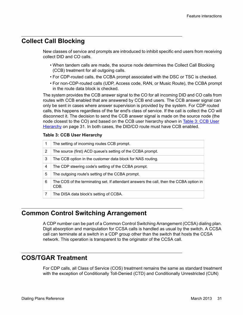
in the route data block is checked.The system provides the CCB answer signal to the CO for all incoming DID and CO calls fromroutes with CCB enabled that are answered by CCB end users. The CCB answer signal canonly be sent in cases where answer supervision is provided by the system. For CDP routedcalls, this happens regardless of the far end's class of service. If the call is collect the CO willdisconnect it. The decision to send the CCB answer signal is made on the source node (thenode closest to the CO) and based on the CCB user hierarchy shown in Table 3: CCB UserHierarchy on page 31. In both cases, the DID/CO route must have CCB enabled.
Table 3: CCB User Hierarchy
1 The setting of incoming routes CCB prompt.
2 The source (first) ACD queue's setting of the CCBA prompt.
3 The CCB option in the customer data block for NAS routing.
4 The CDP steering code's setting of the CCBA prompt.
5 The outgoing route's setting of the CCBA prompt.
6 The COS of the terminating set. If attendant answers the call, then the CCBA option inCDB.
7 The DISA data block's setting of CCBA.
Common Control Switching ArrangementA CDP number can be part of a Common Control Switching Arrangement (CCSA) dialing plan.Digit absorption and manipulation for CCSA calls is handled as usual by the switch. A CCSAcall can terminate at a switch in a CDP group other than the switch that hosts the CCSAnetwork. This operation is transparent to the originator of the CCSA call.
COS/TGAR TreatmentFor CDP calls, all Class of Service (COS) treatment remains the same as standard treatmentwith the exception of Conditionally Toll-Denied (CTD) and Conditionally Unrestricted (CUN)
Feature interactions
Dialing Plans Reference March 2013 31
COS, which are treated as unrestricted (UNR). Users with an FR2 class of service can originatelocal CDP calls but cannot originate CDP calls to distant switches. Trunk Group AccessRestrictions (TGAR) are ignored for the purpose of routing CDP calls.
Direct Inward DialingBecause a CDP DN can be up to 10 digits, the capability of inserting up to 8 leading digits ona DID trunk is supported.
DisplayThe following lists how a digit-display telephone handles CDP calls.
• Outgoing CDP Call — The complete dialed CDP DN displays at the originating set.
• Incoming CDP Call — The trunk access code and member number of the incoming trunkroute display.
• Internal CDP Call — At the originating telephone, the complete dialed CDP DN displays.If the call hunts or is picked up by another station, the internal DN of the answering stationdisplays. At the terminating telephone, the internal DN of the originating telephonedisplays.
• Network Call Transfer — Network Call Transfer (NXFER) interacts with CDP calls in thesame manner as ESN network calls. Refer to Basic Network Feature Fundamentals(NN43001-579) for a full description of NXFER.
End-to-End SignalingEnd-to-End Signaling is enabled for CDP calls.
HuntingHunting across different switches in a CDP group is not supported. Standard Hunting can beapplied to local CDP calls.
Interchangeable Numbering Plan Area codesBecause the Interchangeable Numbering Plan Area (NPA) codes plan removes therequirement that the second digit in an NPA is a zero (0) or a one (1), the Toll Denied (TLD)
Coordinated Dialing Plan description
32 Dialing Plans Reference March 2013Comments? [email protected]

class of service is no longer a reliable way to toll-deny sets. To reliably toll-deny sets, the CodeRestriction or New Flexible Code Restriction (NFCR) feature must be used.
Message CenterThe message center capability is not supported across CDP switches. However, it operatesas normal locally.
Federal Communication Commission Equal Access CarrierAccess Code Expansion impact
In May 1991, the Federal Communications Commission (FCC) mandated that CallAggregators (CA) enable customers equal access to interexchange carriers. This enablescallers to use interexchange carriers regardless of the CA's prescribed carrier. As a concessionto CAs, the FCC permitted the optional restriction of direct dialed Equal Access toll calls.
Any call preceded by a Carrier Access Code (CAC) is considered to be an Equal Access call.The CAC consists of an Equal Access identifier and a Carrier Identification Code (CIC) thatidentify the desired interexchange carrier for a given call. The FCC Equal Access CACExpansion enables the Equal Access identifier to be expanded from two to three digits, andthe CIC to be expanded from three to four digits. Table Table 4: Original and expanded CACformats on page 33 provides examples of both the original and expanded CAC formats.
Table 4: Original and expanded CAC formats
CAC formats Equal Access Identifier Carrier Identification CodeOriginal 10 XXX
Expanded 101 XXXX
Along with the introduction of the expanded CAC, the FCC Equal Access CAC Expansionfeature also eliminates the Selective Carrier Restriction method capabilities, while retainingthe General Carrier Restriction capabilities. This results in a single restriction method which isreferred to as Equal Access toll call restriction.
Dialing Plan considerationsThe CAC formats and time frames that are supported are provided in Table 5: CAC supportedformats on page 34. This table assists Network Dial Plan Administrators in planning for theCAC expansion. See Table 6: CAC format interactions on page 34 for the CAC formatinteractions.
Federal Communication Commission Equal Access Carrier Access Code Expansion impact
Dialing Plans Reference March 2013 33
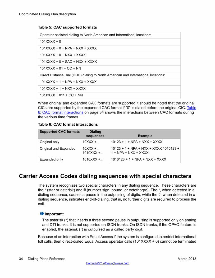
Table 5: CAC supported formats
Operator-assisted dialing to North American and International locations:
101XXXX + 0
101XXXX + 0 + NPA + NXX + XXXX
101XXXX + 0 + NXX + XXXX
101XXXX + 0 + SAC + NXX + XXXX
101XXXX + 01 + CC + NN
Direct Distance Dial (DDD) dialing to North American and International locations:
101XXXX + 1 + NPA + NXX + XXXX
101XXXX + 1 + NXX + XXXX
101XXXX + 011 + CC + NN
When original and expanded CAC formats are supported it should be noted that the originalCICs are supported by the expanded CAC format if "0" is dialed before the original CIC. Table6: CAC format interactions on page 34 shows the interactions between CAC formats duringthe various time frames.
Table 6: CAC format interactions
Supported CAC formats Dialingsequences Example
Original only 10XXX +... 10123 + 1 + NPA + NXX + XXXX
Original and Expanded 10XXX +...1010XXX +...
10123 + 1 + NPA + NXX + XXXX 1010123 +1 + NPA + NXX + XXXX
Expanded only 1010XXX +... 1010123 + 1 + NPA + NXX + XXXX
Carrier Access Codes dialing sequences with special charactersThe system recognizes two special characters in any dialing sequence. These characters arethe * (star or asterisk) and # (number sign, pound, or octothorpe). The *, when detected in adialing sequence, causes a pause in the outpulsing of digits, while the #, when detected in adialing sequence, indicates end-of-dialing, that is, no further digits are required to process thecall.
Important:The asterisk (*) that inserts a three second pause in outpulsing is supported only on analogand DTI trunks. It is not supported on ISDN trunks. On ISDN trunks, if the OPAO feature isenabled, the asterisk (*) is outpulsed as a called party digit.
Because of an interaction with Equal Access if the system is configured to restrict internationaltoll calls, then direct-dialed Equal Access operator calls (101XXXX + 0) cannot be terminated
Coordinated Dialing Plan description
34 Dialing Plans Reference March 2013Comments? [email protected]
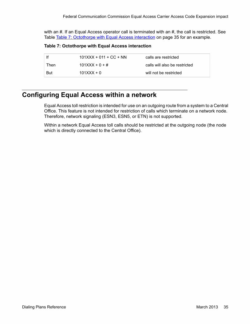
with an #. If an Equal Access operator call is terminated with an #, the call is restricted. SeeTable Table 7: Octothorpe with Equal Access interaction on page 35 for an example.
Table 7: Octothorpe with Equal Access interaction
If 101XXX + 011 + CC + NN calls are restricted
Then 101XXX + 0 + # calls will also be restricted
But 101XXX + 0 will not be restricted
Configuring Equal Access within a networkEqual Access toll restriction is intended for use on an outgoing route from a system to a CentralOffice. This feature is not intended for restriction of calls which terminate on a network node.Therefore, network signaling (ESN3, ESN5, or ETN) is not supported.
Within a network Equal Access toll calls should be restricted at the outgoing node (the nodewhich is directly connected to the Central Office).
Federal Communication Commission Equal Access Carrier Access Code Expansion impact
Dialing Plans Reference March 2013 35

Coordinated Dialing Plan description
36 Dialing Plans Reference March 2013Comments? [email protected]

Chapter 5: Flexible Numbering Plandescription
Navigation• Introduction on page 37
• On-net dialing on page 38
• Off-net dialing on page 39
IntroductionFlexible Numbering Plan (FNP) accommodates Global Numbering Plan (GNP) requirementsby modifying the Electronic Switched Network (ESN) dialing plan. The dialing plans are dividedinto two areas:
• On-net dialing — Involves all possible dialing situations required when dialing to a stationlocated within the Local (private) Network.
• Off-net dialing — Involves all possible dialing situations required when dialing to a stationthat is not part of the Local Network (typically the Public Numbering Plan).
FNP is enhanced to include the ability to inhibit the time-out handling process for:
• ESN Basic Alternate Route Selection (BARS)• Network Alternate Route Selection (NARS), Special Numbers (SPN)• Coordinated Dialing Plan (CDP), Trunk Steering Codes (TSC)
The FNP enhancement ensures that all digits are collected prior to trunk seizure. Thisenhancement meets Chinese requirements.
Network Alternate Route Selection (NARS) package 58 is a prerequisite for FNP. FNP interactswith both NARS and CDP to introduce:
• Universal Numbering Plan (UNP)• Transferable Directory Numbers (TNDN)• Group Dialing Plan (GDP)
Dialing Plans Reference March 2013 37
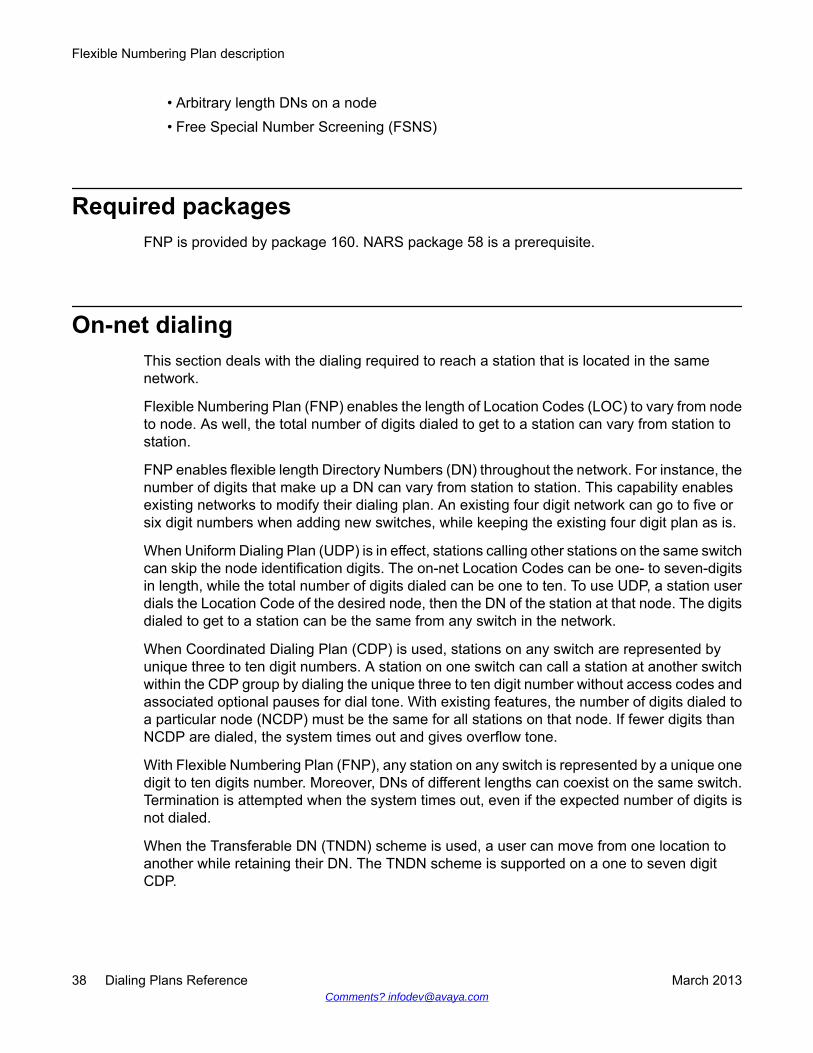
• Arbitrary length DNs on a node• Free Special Number Screening (FSNS)
Required packagesFNP is provided by package 160. NARS package 58 is a prerequisite.
On-net dialingThis section deals with the dialing required to reach a station that is located in the samenetwork.
Flexible Numbering Plan (FNP) enables the length of Location Codes (LOC) to vary from nodeto node. As well, the total number of digits dialed to get to a station can vary from station tostation.
FNP enables flexible length Directory Numbers (DN) throughout the network. For instance, thenumber of digits that make up a DN can vary from station to station. This capability enablesexisting networks to modify their dialing plan. An existing four digit network can go to five orsix digit numbers when adding new switches, while keeping the existing four digit plan as is.
When Uniform Dialing Plan (UDP) is in effect, stations calling other stations on the same switchcan skip the node identification digits. The on-net Location Codes can be one- to seven-digitsin length, while the total number of digits dialed can be one to ten. To use UDP, a station userdials the Location Code of the desired node, then the DN of the station at that node. The digitsdialed to get to a station can be the same from any switch in the network.
When Coordinated Dialing Plan (CDP) is used, stations on any switch are represented byunique three to ten digit numbers. A station on one switch can call a station at another switchwithin the CDP group by dialing the unique three to ten digit number without access codes andassociated optional pauses for dial tone. With existing features, the number of digits dialed toa particular node (NCDP) must be the same for all stations on that node. If fewer digits thanNCDP are dialed, the system times out and gives overflow tone.
With Flexible Numbering Plan (FNP), any station on any switch is represented by a unique onedigit to ten digits number. Moreover, DNs of different lengths can coexist on the same switch.Termination is attempted when the system times out, even if the expected number of digits isnot dialed.
When the Transferable DN (TNDN) scheme is used, a user can move from one location toanother while retaining their DN. The TNDN scheme is supported on a one to seven digitCDP.
Flexible Numbering Plan description
38 Dialing Plans Reference March 2013Comments? [email protected]

Off-net dialingThis section deals with the dialing required to reach a location that is not part of the localnetwork, typically a public exchange station, and stations that are part of another privatenetwork.
FNP is used to accommodate dialing plans which are not based on a fixed length number ofdigits as the North American Numbering Plan (NANP) is. In North America the dialing plansare fixed length, NXX + XXXX or NPA + NXX + XXXX and ESN dialing plan formats aredesigned to respond to these consistent dialing patterns. Since this is not the caseinternationally, FNP is introduced to enable users to dial numbers of varying lengths toterminate at a destination. Flexibility of the number of digits dialed is achieved by using SpecialNumbers (SPNs) that utilize the Supplemental Digit Restriction or Recognition (SDRR)capability.
ESN enabled a customer to dial off-network numbers. These numbers were recognized at aNARS or BARS switch and translation of the Numbering Plan Area (NPA), Office Code (NXX),or SPN with SDRR determined the treatment for the call.
SDRR is applied after translating the NPA, NXX, or SPN at an intelligent NARS or BARSswitch.
Important:The use of the Alternate Routing Remote Number (ARRN) SDRR capability increases themaximum number of digits that can be analyzed for a SPN from 11 to 16.
Digit string processing stops until the expected digits have been received. The expected digitsare then compared to the numbers defined in the SDDR table:
• If a match is found and specified as a recognized DID or DDD number terminating at aConventional Main switch (recognition takes place at the last intelligent NARS or BARSswitch), Route Selection with the Route List Index defined for the NPA, NXX, or SPNnumber is performed. A special digit manipulation is applied so that the proper numbersare outpulsed to terminate directly at the station or attendant of the Conventional Mainswitch. If the trunk is any trunk type other than Tie, then the termination is processed bythe current software with Digit Manipulation if necessary.
• Otherwise, the call is passed to Route Selection with the Route List Index (RLI) associatedwith that NPA, NXX, or SPN number.
ESN did not enable alternate routing for these numbers. In countries not on the North Americancontinent, this was a major drawback because it led to configuration problems for SPNnumbers.
With FNP a new type of number is introduced in the SDRR block. It is called an AlternateRouting Remote Number (ARRN). Following each SPN (and only SPNs), a customer can
Off-net dialing
Dialing Plans Reference March 2013 39

configure ARRNs. For each of these numbers, it is also possible to configure an AlternateRoute List Index (ARLI).
Call processing follows the same steps as previously mentioned. The expected digits arecompared to the numbers defined in the SDRR table and one of the following occurs:
• If a match is found and specified as a recognized ARRN number, Route Selection withthe ARLI defined for that number is performed.
• If a match is not found, Route Selection is called with the RLI found in the table. (One RLIper SPN number).
Flexible Numbering Plan description
40 Dialing Plans Reference March 2013Comments? [email protected]

Chapter 6: Flexible Numbering Planoperation
Navigation• On-net dialing on page 41
• Digit display with Integrated Services Digital Network on page 50
• Off-net dialing on page 53
• Vacant Number Routing on page 60
• Free Calling Area Screening on page 60
• Free Special Number Screening on page 60
• Capacity expansion on page 61
• Feature interactions on page 62
On-net dialingThis section deals with the dialing required to reach a station which is located in the samenetwork. Any station in the network is represented by a flexible number of digits. This includesthe use of Uniform Dialing Plan (UDP) such as Location Code (LOC) + Directory Number (DN),or Universal Numbering Plans; for example, Coordinated Dialing Plan (CDP).
Location Code (LOC)Flexible length LOC enables three- to seven-digit LOCs. Currently, the flexible length LOCcode does not change the length of the number that a user can dial, but only changes whichportions of the number are recognized as different components. Therefore, if a LOC is dialed,seven digits are expected before any attempt is made to terminate the call.
The Flexible Numbering Plan (FNP) feature enables the specification of the total number ofdigits, up to ten, which are required to terminate on a station at a particular node. As well, oneto seven digit LOCs are allowed.
Dialing Plans Reference March 2013 41

When a LOC is dialed, a Route List Block (RLB) is used to make routing decisions. The numberof digits expected is defined by the response to the Flexible Length (FLEN) prompt, promptedwhen the LOC is defined. FLEN enables the length of the number dialed to be up to ten digits.If the user dials a DN shorter than FLEN, termination is attempted when the octothorpe (#) ispressed or when the Network Alternate Route Selection (NARS) interdigit timer times out. Ifthe FNP package 160 is not equipped or the response to the FLEN prompt is zero (0), thendigit analysis is performed as it was prior to the introduction of FNP.
End-of-dial timingAll NARS end-of-dial timing procedures apply to FNP along with the FNP unique FLENprocessing. If the user dials the number of digits as defined by the response to the FLENprompt, then the software considers dialing as being complete and analyzes the digits for callprocessing purposes.
Important:FLEN is not supported for authcode LAST.
Table 8: Termination for FLEN, LOC lengths and digits dialed on page 42 illustrates whenFNP attempts termination for various FLEN settings, LOC lengths, and digits dialed.
Table 8: Termination for FLEN, LOC lengths and digits dialed
LOC + DNnumber of digits m = 1 - 7 FLEN - m
Digits expected (FLEN) Length ofLOC
Digitsdialed
Termination
7 3 7 right away
7 3 6 following # or time out
7 2 7 right away
7 2 6 following # or time out
10 7 10 right away
10 5 9 following # or time out
10 5 4 not possible
10 7 18 when 10 digits are dialed accordingto CDP, BARS, or NARS operation
Coordinated Dialing PlanWhen Coordinated Dialing Plan (CDP) is used, stations are represented by unique three toten digit numbers. CDP uses Local Steering Codes (LSC), Distant Steering Codes (DSC), or
Flexible Numbering Plan operation
42 Dialing Plans Reference March 2013Comments? [email protected]
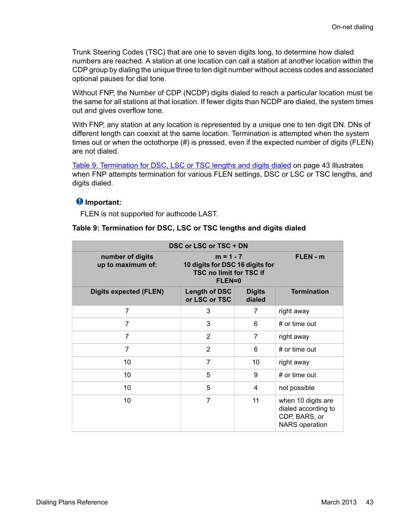
Trunk Steering Codes (TSC) that are one to seven digits long, to determine how dialednumbers are reached. A station at one location can call a station at another location within theCDP group by dialing the unique three to ten digit number without access codes and associatedoptional pauses for dial tone.
Without FNP, the Number of CDP (NCDP) digits dialed to reach a particular location must bethe same for all stations at that location. If fewer digits than NCDP are dialed, the system timesout and gives overflow tone.
With FNP, any station at any location is represented by a unique one to ten digit DN. DNs ofdifferent length can coexist at the same location. Termination is attempted when the systemtimes out or when the octothorpe (#) is pressed, even if the expected number of digits (FLEN)are not dialed.
Table 9: Termination for DSC, LSC or TSC lengths and digits dialed on page 43 illustrateswhen FNP attempts termination for various FLEN settings, DSC or LSC or TSC lengths, anddigits dialed.
Important:FLEN is not supported for authcode LAST.
Table 9: Termination for DSC, LSC or TSC lengths and digits dialed
DSC or LSC or TSC + DNnumber of digits
up to maximum of:m = 1 - 7
10 digits for DSC 16 digits forTSC no limit for TSC if
FLEN=0
FLEN - m
Digits expected (FLEN) Length of DSCor LSC or TSC
Digitsdialed
Termination
7 3 7 right away
7 3 6 # or time out
7 2 7 right away
7 2 6 # or time out
10 7 10 right away
10 5 9 # or time out
10 5 4 not possible
10 7 11 when 10 digits aredialed according toCDP, BARS, orNARS operation
On-net dialing
Dialing Plans Reference March 2013 43

End-of-dial timingAll NARS end-of-dial timing procedures apply to FNP along with the FNP unique FLENprocessing. If the user dials the number of digits as defined by the response to the FLENprompt, then the software considers dialing as being complete and analyzes the digits for callprocessing purposes.
For TSC the default value for Inhibit Time Out Handler (ITOH) is 'NO', which initiates an attemptto terminate the call. If ITOH is set to 'YES' then the call is not terminated if the NARS InterdigitTimer (NIT) expires before the number of digits dialed reaches the FLEN value.
Universal Numbering PlanCurrently, CDP is capable of using LSC, DSC, or TSC that are one to seven digits long. TheGlobal Networking Requirement calls for three to seven digit Transferable DNs (TNDNs)across the network. Furthermore, the TNDNs must be able to have variable lengths, even onthe same node. In order to fulfill this requirement, one to seven digit steering codes are used.The maximum number of digits allowed was expanded from four to seven digits, and themaximum number of steering codes allowed was expanded from 5000 to 10 000. With theintroduction of FNP the maximum number of steering codes has again been increased to 32000.
Figure 3: Universal numbering plan with transferable DNs on page 45 shows an example ofthe Universal Numbering Plan (UNP) network with TNDNs. This network uses three-digit DSCand LSC.
Flexible Numbering Plan operation
44 Dialing Plans Reference March 2013Comments? [email protected]

Figure 3: Universal numbering plan with transferable DNs
Table 10: Call Routing software configuration on page 45 provides an overview of thesoftware configuration required to route calls between nodes.
Table 10: Call Routing software configuration
Distant steeringcode
Route blocklist Entry
Routenumber
Digitmanipulation
index
Digitsto
deleteA to B: 333 1 1 1 1 3
1 2 2 2 0
A to C: 444 2 1 2 1 3
2 2 1 2 0
On-net dialing
Dialing Plans Reference March 2013 45
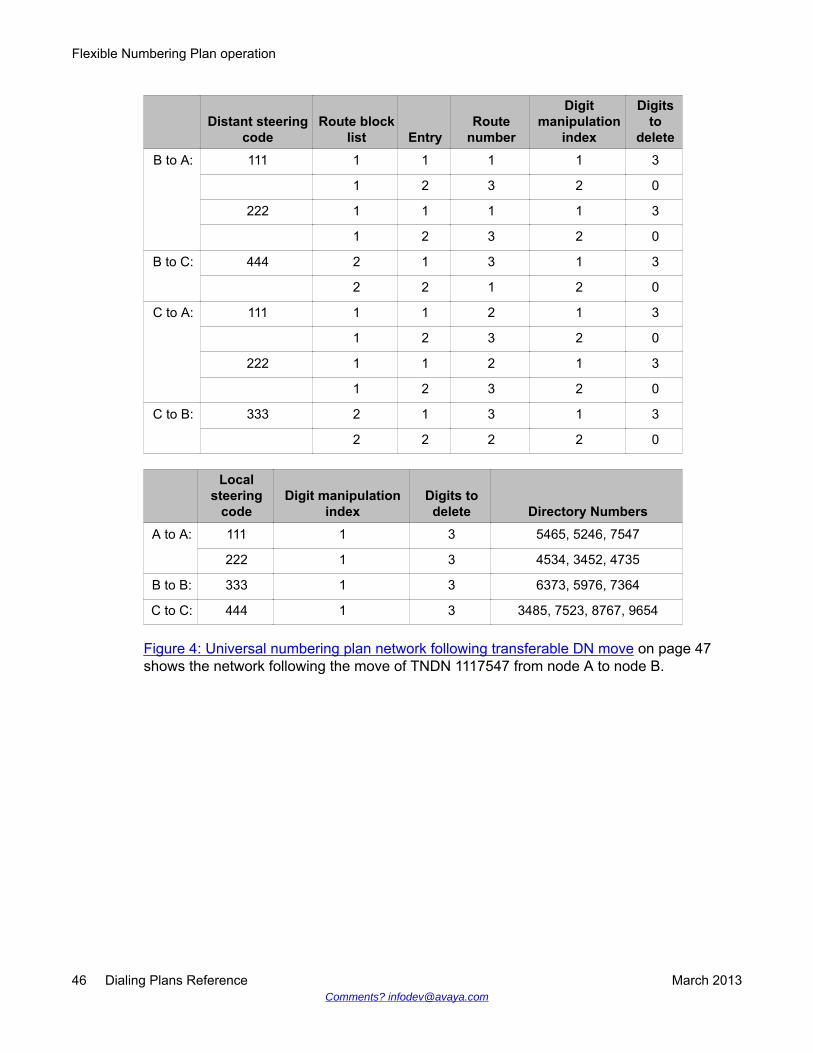
Distant steeringcode
Route blocklist Entry
Routenumber
Digitmanipulation
index
Digitsto
deleteB to A: 111 1 1 1 1 3
1 2 3 2 0
222 1 1 1 1 3
1 2 3 2 0
B to C: 444 2 1 3 1 3
2 2 1 2 0
C to A: 111 1 1 2 1 3
1 2 3 2 0
222 1 1 2 1 3
1 2 3 2 0
C to B: 333 2 1 3 1 3
2 2 2 2 0
Localsteering
codeDigit manipulation
indexDigits todelete Directory Numbers
A to A: 111 1 3 5465, 5246, 7547
222 1 3 4534, 3452, 4735
B to B: 333 1 3 6373, 5976, 7364
C to C: 444 1 3 3485, 7523, 8767, 9654
Figure 4: Universal numbering plan network following transferable DN move on page 47shows the network following the move of TNDN 1117547 from node A to node B.
Flexible Numbering Plan operation
46 Dialing Plans Reference March 2013Comments? [email protected]

Figure 4: Universal numbering plan network following transferable DN move
Table 11: Software configuration after move of TNDN 1117547 on page 47 provides anoverview of the software configuration following the move of TNDN 1117547.
Table 11: Software configuration after move of TNDN 1117547
DistantSteering code
Routeblock list Entry
Routenumber
Digitmanipulation
index
Digitsto
deleteA to B: 333 1 1 1 1 3
1 2 2 2 0
1117547 2 1 1 2 0
On-net dialing
Dialing Plans Reference March 2013 47
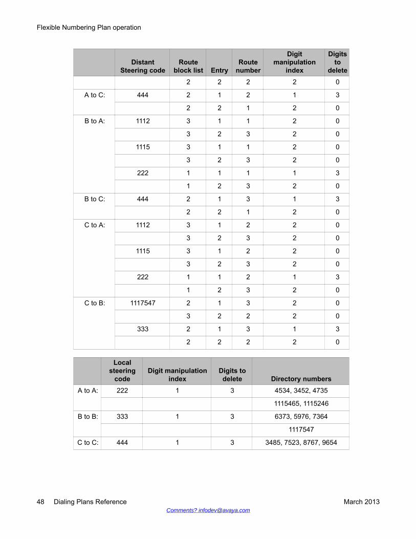
DistantSteering code
Routeblock list Entry
Routenumber
Digitmanipulation
index
Digitsto
delete2 2 2 2 0
A to C: 444 2 1 2 1 3
2 2 1 2 0
B to A: 1112 3 1 1 2 0
3 2 3 2 0
1115 3 1 1 2 0
3 2 3 2 0
222 1 1 1 1 3
1 2 3 2 0
B to C: 444 2 1 3 1 3
2 2 1 2 0
C to A: 1112 3 1 2 2 0
3 2 3 2 0
1115 3 1 2 2 0
3 2 3 2 0
222 1 1 2 1 3
1 2 3 2 0
C to B: 1117547 2 1 3 2 0
3 2 2 2 0
333 2 1 3 1 3
2 2 2 2 0
Localsteering
codeDigit manipulation
indexDigits todelete Directory numbers
A to A: 222 1 3 4534, 3452, 4735
1115465, 1115246
B to B: 333 1 3 6373, 5976, 7364
1117547
C to C: 444 1 3 3485, 7523, 8767, 9654
Flexible Numbering Plan operation
48 Dialing Plans Reference March 2013Comments? [email protected]
Group dialing planGroup Dialing Plan (GDP) enables coordinated dialing within a larger network that usingLocation Codes (LOC).
Each group has an LOC that has to be dialed from outside the group as a prefix to the groupCDP: that is, have LOC and CDP working together. In this case, the number dialed to a stationcan be different when dialed from different locations.
When GDP is used, the maximum number of digits allowed for either LOC+DN, LSC+DN, orDSC+DN cannot exceed 10 digits if the dialing plan is to perform properly. Figure 5: Groupdialing plan on page 50 illustrates a GDP network.
In order to get to station 6373 on node B:
• User 2565 on node A dials 501-3336373.
• User 3485 on node C dials 3336373.
• User 5976 on node B dials 6373.
On-net dialing
Dialing Plans Reference March 2013 49
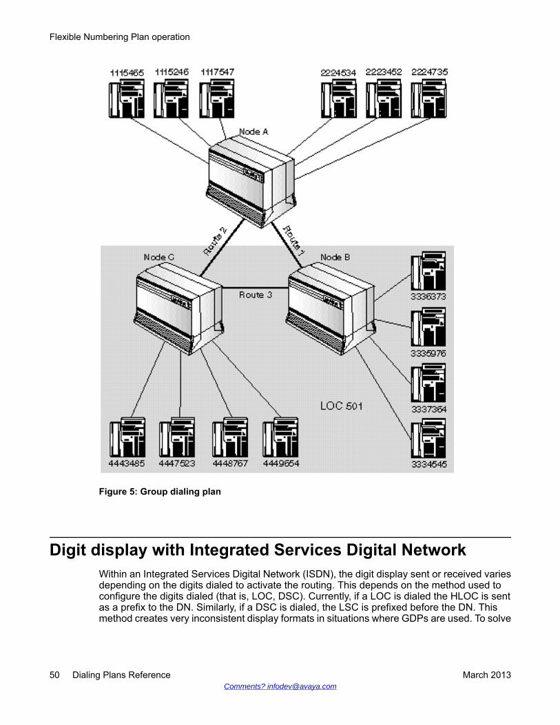
Figure 5: Group dialing plan
Digit display with Integrated Services Digital NetworkWithin an Integrated Services Digital Network (ISDN), the digit display sent or received variesdepending on the digits dialed to activate the routing. This depends on the method used toconfigure the digits dialed (that is, LOC, DSC). Currently, if a LOC is dialed the HLOC is sentas a prefix to the DN. Similarly, if a DSC is dialed, the LSC is prefixed before the DN. Thismethod creates very inconsistent display formats in situations where GDPs are used. To solve
Flexible Numbering Plan operation
50 Dialing Plans Reference March 2013Comments? [email protected]

this problem, a new option is introduced to the DSC prompt sequence that enables a user toidentify what prefixes the DN sent. The options are HLOC, LSC, or nothing.
LOC+DN dialingDialing Party sees: LOC+DN of answering party. Called Party sees: LOC+DN of dialingparty.
CDP dialingDialing Party sees: LSC+DN of answering party. Called Party sees: LSC+DN of dialing party.
Group dialingDepending on the option chosen on a per DSC basis, any of the following can be seen:
Dialing Party sees: LOC+DN or LSC+DN or DN of answering party. Called Party sees: LOC+DN or LSC+DN or DN of dialing party.
Figure 6: Sample GDP network on page 52 is an example of a network that uses the GDP.This sample network is used to show what various sets within the network display.
Digit display with Integrated Services Digital Network
Dialing Plans Reference March 2013 51
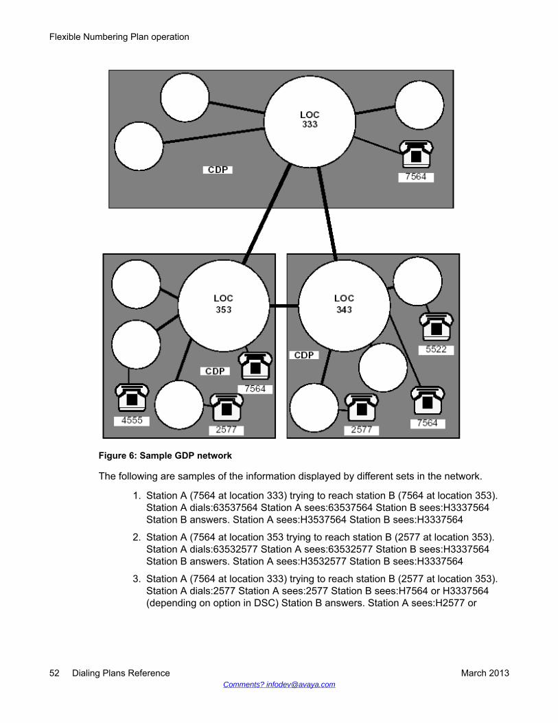
Figure 6: Sample GDP network
The following are samples of the information displayed by different sets in the network.
1. Station A (7564 at location 333) trying to reach station B (7564 at location 353).Station A dials:63537564 Station A sees:63537564 Station B sees:H3337564Station B answers. Station A sees:H3537564 Station B sees:H3337564
2. Station A (7564 at location 353 trying to reach station B (2577 at location 353).Station A dials:63532577 Station A sees:63532577 Station B sees:H3337564Station B answers. Station A sees:H3532577 Station B sees:H3337564
3. Station A (7564 at location 333) trying to reach station B (2577 at location 353).Station A dials:2577 Station A sees:2577 Station B sees:H7564 or H3337564(depending on option in DSC) Station B answers. Station A sees:H2577 or
Flexible Numbering Plan operation
52 Dialing Plans Reference March 2013Comments? [email protected]

H3532577 (depending on option in DSC) Station B sees:H7564 or H3337564(depending on option in DSC)
4. Station A 333-7564 trying to reach station B 353-4555. Station A dials:4555 StationA sees:4555 Station B sees:H3337564(LOC option chosen in DSC) Station Banswers. Station A sees:H3534555(LOC option chosen in DSC) Station Bsees:H3337564(LOC option chosen in DSC)
Off-net dialingThis section deals with dialing required to reach a location which is not part of the local network.This is typically a public exchange station, but it also includes stations that are part of anotherprivate network.
FNP introduces alternative routing for Direct Inward Dialing (DID) or Direct Distant Dialing(DDD) Special Numbers (SPNs). The main purpose of alternative routing for DID or DDD SPNnumbers is to define and enable alternate routing for calls recognized as remote DID or DDDSPN numbers within a private network. It also allows for low cost routing of off-net numbers.
Alternative routing for DID or DDD SPN numbers introduces a new type of number in theSupplemental Digit Restriction or Recognition (SDRR) block: Alternate Routing RemoteNumber (ARRN). Each ARRN has an Alternate Route List Index (ARLI) defined for it.
SDRR is applied after translating the SPN at an intelligent NARS or BARS switch. If a matchis found and specified as an ARRN number, Route Selection is performed with the ARLI definedfor that number.
Special Numbers (SPN)Currently, the length of an SPN can be one to eleven digits. When the SPN is dialed, the trunkis seized immediately. Any digits dialed afterwards are outpulsed. With the FNP feature, thesystem waits for FLEN of digits up to a maximum of 16 digits before attempting termination. Ifthe user dials fewer than the FLEN of digits, termination is only attempted when the octothorpe# is pressed or when the NARS interdigit timer times out. If the FNP package is not equippedor if the value of FLEN is 0, then current operations are followed.
Important:FLEN is not supported for authcode LAST.
If the SPN in question is 0, 00, 01, 011, 411, 611, 911, 800 or 1800 then the North Americanoperation can be altered by setting the INPL prompt to YES. This allows a flexible numberof digits to be dialed and termination to be attempted only when the octothorpe # is pressedor when the NARS interdigit timer times out. For example, if SPN 00 is defined with FLEN= 0 and INPL = NO, termination can be attempted immediately after the SPN is entered andadditional dialed digits are NOT outpulsed.
Off-net dialing
Dialing Plans Reference March 2013 53

Table 12: Termination for FLEN settings, SPN lengths, and digits dialed on page 54 illustrateswhen FNP attempts termination for various FLEN settings, SPN lengths, and digits dialed.
Table 12: Termination for FLEN settings, SPN lengths, and digits dialed
SPN + DNm = 1 -1 11 FLEN - m
Number of digitsDigit expected (FLEN) Length of SPN Digits dialed Termination
1 1 1 right way
3 3 3 right away
7 2 7 right away
7 2 6 # or time out
12 11 12 right away
16 7 16 right away
16 5 9 # or time out
16 5 4 not possible
0 according to CDP, BARS,or NARS operation
An off-net number is recognized at a NARS or BARS intelligent switch. Translation of the SPNnumber identifies the method of treatment for the call.
If the response to SDRR in LD 90 is any response other than NONE, SDRR is applied. Thenone of the following occurs:
• If the number is "denied" (that is, response to SDRR is DENY): standard call blockingtakes place.
• If the number is defined as terminating at the local switch (that is, response to SDRR isLDID or LDDD): the call is terminated at the station DN for DID and at the Attendant DNfor DDD.
• If the number is defined as terminating at a remote system or Conventional Main switch(that is, response to SDRR is DID or DDD): Route Selection with the Route List Index(RLI) defined for that SPN is performed. The call is then routed to the dialed station forDID numbers or to the attendant for DDD numbers.
- If the trunk route used to route the call is a Tie trunk route, then a special digitmanipulation is applied so that the proper numbers are outpulsed to terminatedirectly at the station or attendant of the Conventional Main switch.
Flexible Numbering Plan operation
54 Dialing Plans Reference March 2013Comments? [email protected]
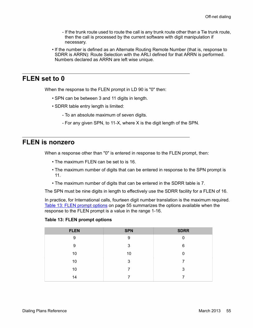
- If the trunk route used to route the call is any trunk route other than a Tie trunk route,then the call is processed by the current software with digit manipulation ifnecessary.
• If the number is defined as an Alternate Routing Remote Number (that is, response toSDRR is ARRN): Route Selection with the ARLI defined for that ARRN is performed.Numbers declared as ARRN are left wise unique.
FLEN set to 0When the response to the FLEN prompt in LD 90 is "0" then:
• SPN can be between 3 and 11 digits in length.
• SDRR table entry length is limited:
- To an absolute maximum of seven digits.
- For any given SPN, to 11-X, where X is the digit length of the SPN.
FLEN is nonzeroWhen a response other than "0" is entered in response to the FLEN prompt, then:
• The maximum FLEN can be set to is 16.
• The maximum number of digits that can be entered in response to the SPN prompt is11.
• The maximum number of digits that can be entered in the SDRR table is 7.
The SPN must be nine digits in length to effectively use the SDRR facility for a FLEN of 16.
In practice, for International calls, fourteen digit number translation is the maximum required. Table 13: FLEN prompt options on page 55 summarizes the options available when theresponse to the FLEN prompt is a value in the range 1-16.
Table 13: FLEN prompt options
FLEN SPN SDRR9 9 0
9 3 6
10 10 0
10 3 7
10 7 3
14 7 7
Off-net dialing
Dialing Plans Reference March 2013 55
FLEN SPN SDRR16 9 7
16 10 6
16 11 0
14 5 7
The system translation capability is illustrated in the following example:
An end user has offices in Holland and the United Kingdom (UK).
It is commonplace for calls to be placed from the customer's UK offices to their Dutch officesby dialing the international Public Service Telephone Network (PSTN), even though privatecircuits and a private numbering plan exist for the routing of such calls.
The customer requires that the dialed digits be analyzed down to the third to last digit, in orderto recognize their assigned Direct Dial Inward (DDI) range.
The international PSTN number is: 010 31 250 3731XX
The FLEN, determined by the actual full number length is, 14.
Enter the following in LD 90:
Table 14: LD 90 : Define Special Number translation.
Prompt Response DescriptionSPN* 010 31 Special Number translation
SDRR ARRN Supplemental Digit Restriction or Recognition
ARRN 250 373 1 Alternate Routing Remote Number
*Only one needed for Holland.
Important:To ensure proper operation in the previous example the value input in response to the FLENprompt must be at least 14. To obtain this result, add the number of digits entered in responseto the SPN and ARRN prompts to the number of remaining digits required to route the callcorrectly. In the previous example five digits were entered in response to the SPN prompt,seven digits were entered in response to the ARRN prompt, and two digits were required toterminate the call at the correct number yielding a total of 14 digits. If FLEN were set to 12in the previous example, then the last two digits would be lost, and the call would notterminate.
Flexible Numbering Plan operation
56 Dialing Plans Reference March 2013Comments? [email protected]
End-of-dial timingFor SPN codes, the default value for ITOH is 'NO' allowing termination of the call to beattempted. If ITOH is set to 'YES' then the call is not terminated if the NIT timer expires beforethe number of digits dialed reaches the value entered for FLEN.
Numbering Plan Area (NPA) and NXXFlexible length Numbering Plan Area (NPA) and NXX codes allow 3 to 10 digit (4 to 11 for 1+dialing) NPAs and NXXs. The flexible length NPAs and NXXs do not change the number ofdigits a user is allowed to dial, but only change which portions of the number are recognizedas different components. If an NPA is dialed, 10 digits (11 for 1+ dialing) are expected beforean attempt to terminate is made. If an NXX is dialed, 7 digits (8 for 1+ dialing) are expectedbefore an attempt to terminate is made. The FNP feature does not change the operation ofNPA and NXX dialing.
NPA + NXX + XXXX total of 10 digits (11 digits for 1+ dialing)
NXX + XXXX total of 7 digits (8 digits for 1+ dialing)
Figure 7: Sample network to illustrate off-net dialing on page 58 illustrates a network whereboth off-net and on-net dialing are used.
Off-net dialing
Dialing Plans Reference March 2013 57
Figure 7: Sample network to illustrate off-net dialing
Table 15: On-net dialing and associated software setting
Canada to Maidenhead AC1 LOC TIE DELETE INSERT FLEN62501234 6 250 2 3 NONE 7
Canada to Paris AC1 LOC TIE DELETE INSERT FLEN
62602234 6 260 2 NONE AC1 7
Canada to Singapore AC1 LOC TIE DELETE INSERT FLEN
Flexible Numbering Plan operation
58 Dialing Plans Reference March 2013Comments? [email protected]
Canada to Maidenhead AC1 LOC TIE DELETE INSERT FLEN62703234 6 270 6 3 NONE 7
Table 16: Off-net dialing and associated software settings
Canada to Maidenhead AC2 SPN TIE CO DELETE INSERT FLEN9-44-628824960 9 44 2 2 AC2 11
9 44 2 NONE 011 11
Canada to Frankfurt AC2 SPN TIE CO DELETE INSERT FLEN
9-49-69821560 9 49 7 NONE 011 10
Canada to Singapore AC2 SPN TIE CO DELETE INSERT FLEN
9-65-4554339 9 65 6 2 AC2 9
9 65 6 NONE 011 9
Paris to Frankfurt AC2 SPN TIE CO DELETE INSERT FLEN
9-49-69821569 9 49 5 NONE 19 10
End-of-dial timingThere can be cases where the requirements dictate that the DNs at a particular location areof varying lengths. In this case, the value of FLEN is set to the maximum DN length for thatparticular location before termination is attempted. If the number of digits dialed is less thanthe maximum DN length defined, the expiration of a timer, or the use of the "fast connect" keyis required to attempt termination.
A new NARS Interdigit Timer (NIT) is introduced in the customer data block. The NIT ispackaged within the NARS package. Therefore, the FNP package is not required for NIT.During dialing, until a valid Network Access Code, LSC, DSC, or TSC is recognized, interdigittiming is done in the same way as it is for a regular call. Once NARS has been accessed, theNIT timer is used to perform interdigit timing. If the NIT timer expires before FLEN digits havebeen dialed, or an octothorpe (#) has been entered to indicate that all digits have been dialed,then an attempt is made to terminate the call.
For TSC and SPN codes if the NIT timer expires before FLEN digits have been dialed, or anoctothorpe (#) has been entered to indicate that all digits have been dialed, then operationdepends on the response to the ITOH prompt. The ITOH option is set for TSC using LD 87and SPN using LD 90.
If ITOH = NO (default) an attempt is made to terminate the call. If ITOH = YES then the call isnot terminated.
Off-net dialing
Dialing Plans Reference March 2013 59

Vacant Number RoutingIn order to keep the Transferable Numbering Plan at a manageable level, Vacant NumberRouting (VNR) is introduced. Instead of changing the numbering trees and steering codes ateach location, all the routing information can be kept at one central location. When a DN istransferred from one location (A) to another (B), routing information at the two locationsinvolved do not have to be changed. Instead all routing information can be stored at a thirdlocation (C) and this would be the only location to have its routing information updated.
If a vacant number is dialed, the call is routed to location C. This location decides where thestation is located, if the station cannot be located then vacant number treatment at theterminating location is given. The DN is not treated as invalid at the location where vacantnumber dialing is in effect. For ISDN in general, and enterprise ISDN variants in particular, thecall crops back to the originator (or as close as possible) to provide the treatment.
Administration of the Transferable Numbering Plan can be located at central switches andsmaller switches can be alleviated of having to administer the entire numbering plan.
Free Calling Area ScreeningThe Free Calling Area Screening (FCAS) feature currently allows a six digit NPA-NXXtranslation which excludes "0" and "1" as the leading digit for NXX. The FCAS operation is notchanged with FNP equipped.
NPA NXX
3 digits 3 digits
Free Special Number ScreeningA new screening capability, Free Special Number Screening (FSNS), is introduced with theFNP feature. 1 to 11 digit SPNs can be screened against three digit XXXs to allow or restrictcalls going to particular XXXs. XXX can be any string of digits from 000 to 999.
SPN XXX
1-11 digits 3 digits
Flexible Numbering Plan operation
60 Dialing Plans Reference March 2013Comments? [email protected]

The following is an example of how to use a one to five digit SPN associated with a five to onedigit XXX for screening purposes:
Input in FSNS table RealSPN XXX SPN XXX
545 192 5 45192
545 192 54 5192
545 192 545 192
545 192 5451 92
545 192 54519 2
Capacity expansion
RLB and DMl expansionIn order to support UNP, the maximum number of RLBs and digit manipulation tables allowedis increased from the current maximum of 255 to 2000. This is necessary as the need for moreroutes and digit manipulation is required for Global Networking. Digit manipulation is allowedfor LSC as a result of the existing Local Steering Code Manipulation (LSCM) feature.
LOC, LSC, DSC TSC expansionThe maximum number of LOCs allowed is increased from 999 to 16 000. The maximumnumber of steering codes allowed are increased from 10 000 to 64 000.
AC1 and AC2 expansionPrior to the introduction of FNP, AC1 and AC2 were either one- or two-digit codes. With FNPequipped, AC1 and AC2 can be one- to four-digit codes.
Capacity expansion
Dialing Plans Reference March 2013 61

Feature interactions
Digital Access Signaling System 2 and Digital Private NetworkSignaling System 1
It is not possible to use NARS on incoming Digital Access Signaling System 2 ( DASS2) andDigital Private Network Signaling System 1 ( DPNSS1) calls. Therefore, an intelligent NARSor BARS switch must be the first DPNSS switch if the call is routed over an DPNSS network.
Directory Number (DN) entriesAll translation entries in the same NARS or BARS translator must be left wise unique as is therequirement for all existing translators.
ESN feature interactionsESN features operate the same way they did prior to the introduction of FNP if FLEN is set tozero. When used along with ISDN, FNP supports features that are currently supported jointlyby ESN and ISDN.
Group Dialing PlanWhen Group Dialing Plan (GDP) is used, the maximum number of digits allowed for either LOC+DN, LSC+DN, or DSC+DN cannot exceed ten digits.
Integrated Services Digital NetworkISDN requires the dialing of all the digits before the number is sent out in the D-channel"SETUP" message. In order to support ISDN with FNP, the dialed digits are sent when theInterdigit Timer (IDT) times out, the maximum number of digits required is dialed, or anoctothorpe (#) is dialed.
Flexible Numbering Plan operation
62 Dialing Plans Reference March 2013Comments? [email protected]
Vacant Number RoutingWith Flexible Numbering Plan Enhancement (FPE), Vacant Number Routing (VNR) is availableonly when FNP is enabled (FNP = YES). Therefore, VNR is only prompted in LD 15 when FNP= YES. When FNP is disabled, VNR is also disabled.
The FNP feature allows the user to define what is to be sent as Calling Line Identification (CLID)and what is to be displayed on the telephone set on a per-DSC basis. The following showswhat is transmitted as CLID when a particular type of number is dialed:
Type of number dialed CLID sentSPN Home NPA + Home NXX+DN
NPA Home NPA + Home NXX+DN
NXX Home NXX + DN
LOC Home LOC +DN
DSC, TSC LSC + DN or LOC+DN or DN
Supplemental Digit Restriction or RecognitionThe Supplemental Digit Restriction or Recognition (SDRR) feature blocks unnecessary loopingthrough the Central Office (CO) or Public Exchange at the terminating switch when an off-netnumber is dialed. This feature applies to NPA, NXX, and SPN calls and works as it always has.However, the restrictions are changed to allow a variable number of digits up to eleven digitsin the digit restriction table, independent of the number of digits entered for the NPA, NXX, orLOC prompts.
The size of the SDRR block for a given SPN number is limited to 64 entries.
With the introduction of the ARRN, up to 16 digits can be analyzed for SPNs.
Transferable DNsTransferable DNs are supported on a one to seven digit CDP. They are not supported whenthe eight to ten digit CDP is used.
Varying length DNsFor a location with DNs of different lengths (for example, five and six digit DNs), the expectednumber of digits for the route going to that location is set to the number of digits of the longest
Feature interactions
Dialing Plans Reference March 2013 63

DN at that location. Termination to the shorter length DNs can only happen when an octothorpeis entered or when the NIT times out.
Flexible Numbering Plan operation
64 Dialing Plans Reference March 2013Comments? [email protected]
Chapter 7: Feature Group D description
Navigation• Introduction on page 65
• Local network and end office switching on page 67
• Originating features on page 68
• Terminating features on page 70
• Interface protocol on page 71
• EANA protocol specifications on page 75
• Hardware on page 78
• Feature interactions on page 81
IntroductionFeature Group D (FGD) provides access to corporate networks from off-network sources.Feature Group D defines interconnection rules between the Local Exchange Carrier (LEC) andan Inter-Exchange Carrier (IEC) such as AT&T or MCI. These rules provide Equal Access (EA),which guarantees that all carriers are processed equally by defining level of service and qualityof transmission. Feature Group D (FGD) provides the following services:
• Routes calls between Local Access and Transport Areas (inter-LATA calls) from pre-subscribed telephones to the IEC's Point of Termination (POT). Individual callingcustomers can designate one IEC to whom inter-LATA calls should be routed.
• Routes all calls prefixed by the Carrier Access Code (CAC) to the user-selected carrier.• Passes dialed digits, Automatic Number Identification (ANI) digits, and other information
to the carrier for billing, screening, routing, and other call services.Equipping systems with Feature Group D (FGD) allows the network owner to operate as anInter-Exchange Carrier (IEC), subject to Local Exchange Carrier (LEC) regulations. The resultis that off-network sources can gain access to corporate networks. A typical Feature Group D(FGD) configuration is shown in Figure 8: Configuration example on page 67. In this case,the corporate network contains Meridian 1 switches.
Dialing Plans Reference March 2013 65
Required packagesFeature Group D (FGD), package number 158, requires the following packages:
• Basic Alternate Route Selection (BARS), package 57
- Network Alternate Route Selection (NARS), package 58, is recommended to supportgreater flexibility and translation capability.
• Network Class of Service (NCOS), package 32
• Basic Routing (BRTE), package 14
The following packages are required for additional optional capabilities:
• Call Detail Recording Expansion (CDRE), package 151, provides Automatic NumberIdentification (ANI) information in the records.
• Digit Display (DDSP), package 19, allows Automatic Number Identification (ANI)display.
• Network Authorization Code (NAUT), package 63, provides Network Authorizationfunctions.
- NAUT requires Basic Authorization Code (BAUT), package 25, and Charge Account(CAB), package 24.
• Automatic Trunk Maintenance (ATM), package 84, allows Automatic Trunk Maintenancecapabilities. ATM cannot be invoked on trunks controlled by a D-channel (DCH).
- ATM requires Tone Detector (TDET), package 65.
• ISDN Primary Rate Interface (PRI) package 146, or ISDN Signaling Link (ISL) package147, is required to provide Automatic Number Identification (ANI) digits as Calling LineIdentification (CLID).
ISDN Signaling (ISDN), package 145, is required for either PRI or ISL.
Feature Group D description
66 Dialing Plans Reference March 2013Comments? [email protected]
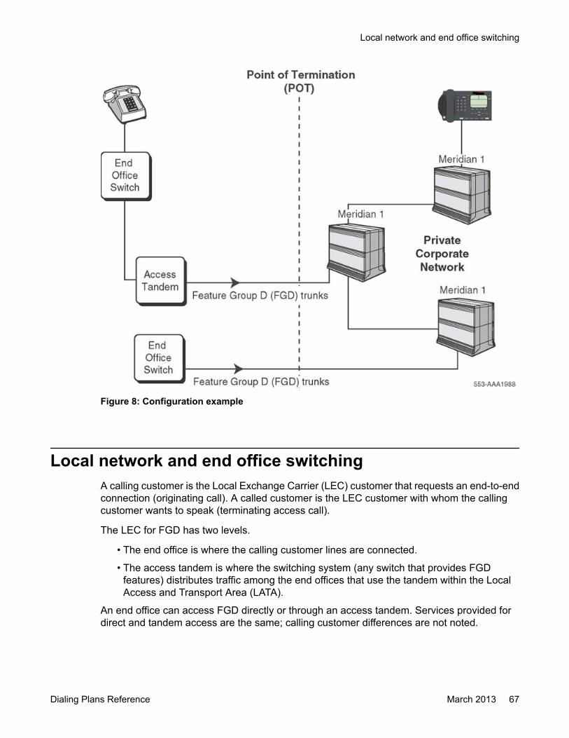
Figure 8: Configuration example
Local network and end office switchingA calling customer is the Local Exchange Carrier (LEC) customer that requests an end-to-endconnection (originating call). A called customer is the LEC customer with whom the callingcustomer wants to speak (terminating access call).
The LEC for FGD has two levels.
• The end office is where the calling customer lines are connected.
• The access tandem is where the switching system (any switch that provides FGDfeatures) distributes traffic among the end offices that use the tandem within the LocalAccess and Transport Area (LATA).
An end office can access FGD directly or through an access tandem. Services provided fordirect and tandem access are the same; calling customer differences are not noted.
Local network and end office switching
Dialing Plans Reference March 2013 67
Originating featuresA calling customer can place only domestic calls. A domestic call originates and terminateswithin World Zone 1 (WZ1).
Important:Currently, a calling customer may not dial outside the North American Dialing Plan. Certainlocations outside the continental United States, but still within World Zone 1 (WZ1), mayrequire international dialing and are not supported under the domestic dialing plan. Forexample, the Caribbean is within WZ1 but requires international dialing capabilities.Therefore, the calling customer in this particular location cannot access the Caribbean.
Domestic dialing planUse the following sequence for domestic calls through FGD
Table 17: Domestic Dialing Plan
(10XXX) + (0/1) +7/10DLegend:
() Parentheses Indicates that the numbers within theparentheses may not be required fordialing.
/ Slash Indicates that either one or the other may beused.
10XXX Designates that the call be handled by theIEC network.
0 Requests Avaya Dial 0 services.
1 May be required for some 7- or 10-digit calls.For example, a 1 may indicate 10-digitdialing.
7/10D Represents the 7 or 10 digit directory numberfor the called customer.
Feature Group D description
68 Dialing Plans Reference March 2013Comments? [email protected]

Pre-subscriptionA pre-subscription Incoming Call (IEC) is the IEC that the calling customer selects to routedomestic calls without a 10XXX designator. By dialing the 10XXX code, you can override thispre-subscribed IEC.
Service Access CodeService Access Codes (SACs) are Number Plan Area (NPA) codes assigned for special use.Normally NPA codes are used to identify specific geographical areas. However, some NPAcodes within the North American Numbering Plan (NANP) are designated as SAC codes toindicate generic services or access capability.
Currently four NPA codes are designated as SAC codes; each is associated with a specificservice or access capability:
• 610 SAC is assigned to Canada for TWX service.• 700 SAC is reserved for the IEC.• 800 SAC is assigned for toll-free numbers.• 900 SAC is reserved for special services such as pay-subscription.
SACs also provide the option to assign access capability to the LEC and IEC network. SACsfurther divide into categories that define the IEC identification requirements.
Ancillary Carrier identification (10-digit translation)Access this category by dialing (1) + SAC-NXX-XXXX. Do not enter the 10XXX access code.The full 10 digits are translated to determine the IEC.
Embodied Carrier identification (6 - digit translation)Access this category by dialing (1) + SAC-NXX-XXXX. Do not enter the 10XXX access code.The 6 digits (SAC-NXX) are translated to determine the IEC.
External Carrier identificationAccess this category by dialing (10XXX) + (0/1) + SAC-NXX-XXXX. The IEC is determined bythe 10XXX access code. If the 10XXX is not dialed, the pre-subscribed IEC routes the call.
Originating features
Dialing Plans Reference March 2013 69

Automatic Number Identification (ANI)For billing and screening purposes, the IEC can have ANI digits precede the called partyaddress. The ANI includes two information digits, followed by the calling customer's area codeand billing number. If the billing number is not available, the information digits are followed bythe area code only.
Signaling protocolFGD can use the following signaling protocols for originating (LEC to IEC) calls:
• Exchange Access North American (EANA) signaling
• Terminating protocol—for test calls only
Carrier test linesThe only test lines supported by Feature Group D (FGD) are those supported by the AvayaCommunication Server 1000M, Communication Server 1000S and Meridian 1 systems.
OutpulsingExchange access signaling is implemented with overlap signaling or outpulsing.
Terminating featuresOnly test calls are supported for outgoing FGD calls.
LEC test linesThe following types of test lines may be provided by the LEC:
• balance (100 type)
• non-synchronous or synchronous
• automatic transmission
• data transmission (107 type)
Feature Group D description
70 Dialing Plans Reference March 2013Comments? [email protected]
• measuring (105 type)
• loop around
• short circuit
• open circuit
Interface protocol
DirectionTrunks are characterized according to the direction that supervisory and address signals areapplied.
• A one-way outgoing trunk from the LEC carries the originating calls.
Important:One-way outgoing trunks, from the LEC to the IEC, do not provide IEC testcapability.
• A one-way incoming trunk to the LEC carries terminating calls.
• A two-way trunk carries both originating and terminating calls.
Signaling protocolThe supported signaling protocols are terminating protocol (for outbound test lines only) andExchange Access North American (EANA) signaling.
Terminating protocolIn addition to the originating signaling protocol, there is one terminating protocol for line testsas follows:
1. The IEC seizes a trunk to the LEC and applies a connect (off-hook) signal to thetrunk.
2. The LEC responds with a wink-start signal, which informs the IEC that the LEC isready to receive the address field.
3. On receipt of this wink-start signal from the LEC, the IEC multifrequency (MF)outpulses the address field.
Interface protocol
Dialing Plans Reference March 2013 71
4. The LEC screens and translates the address field. If the terminating call is deliveredto the appropriate end office, the LEC completes the call to the proper called testline. An IEC may have to establish more than one Point of Termination (POT) toobtain access to an entire LATA.
5. When the called customer answers, answer supervision (off hook) is passed to theIEC from the LEC. The time that the off-hook signal is received by the LEC isrecorded by Automatic Message Accounting (AMA) as the customer answer time.
6. When the call is over, the disconnect sequence is initiated. The time that the on-hook signal is received is recorded by AMA as the disconnect time.
Exchange Access North American (EANA) signalingExchange Access North American (EANA) signaling consists of two fields, the identificationfield and the address field.
• The identification field contains the calling customer's identification number or ANIdigits.
• The address field contains the called number.
This arrangement allows the identification field ( ANI digits) to be pulsed to the IEC before thecalled number. With the addition of overlap pulsing, which initiates pulsing to the IEC beforethe customer has completed dialing, post-dialing delay is minimized. The originating callprocess follows:
1. After the customer dials all but the last four digits of the called number, the LECinitiates actions to seize a trunk to the IEC.
2. The IEC responds to the trunk seizure with a wink-start signal when ready to receivepulsing. The time that the wink-start signal is received is recorded by AutomaticMessage Accounting (AMA) as the IEC connect time.
3. After receiving the wink-start signal from the IEC, the LEC starts MF outpulsing theidentification field.
4. When both customer dialing and outpulsing of the identification field are completed,the LEC outpulses the address field.
5. When the IEC receives all the pulsing information, it responds with anacknowledgment wink.
6. After receiving the acknowledgment wink, the LEC connects the talking path fromthe calling customer to the IEC.
7. After the called customer answers, the answer off-hook signal is sent from the IECto the originating LEC. The time that the off-hook signal is received is recorded byAMA as the customer answer time.
8. When the call is completed, the disconnect sequence is initiated. The time that theon-hook signal is received is recorded by AMA as the disconnect time.
Feature Group D description
72 Dialing Plans Reference March 2013Comments? [email protected]

Carrier classificationInter-Exchange Carrier (IEC) provides connections between Local Access and TransportAreas (LATAs) and serving areas where the calling and called customers are located in WorldZone 1.
International Carrier (INC) provides connections between a customer located in the contiguous48 United States and a customer located outside World Zone 1.
Consolidated Carrier (IEC & INC) combines the services of Inter-Exchange and InternationalCarriers.
When calls are being forwarded to carriers using exchange access signaling, the protocol isinfluenced by the classification of the receiving carrier. The IEC and IEC & INC receive callsdestined for customers located in World Zone 1 with EANA signaling.
Call categories and pulsing formatsCall categories are based on the information dialed by the originating customer. Table 18: Callcategories on page 73 identifies the applicable call categories for FGD switched accessservice.
Table 18: Call categories
Customer dials Call category(10XXX)+(1)+(NPA)+NXX+XXXX - NPA is in area covered byNorth American Numbering Plan
(Inside WZ 1) 1+
(10XXX)+0+(NPA)+NXX+XXXX - NPA is in area covered byNorth American Numbering Plan
(Inside WZ 1) 0+
(1)+SAC+NXX+XXXX 1+(Embodied SAC)
(10XXX)+(1)+SAC+NXX+XXXX 1+(External SAC)
(10XXX)+(0)+SAC+NXX+XXXX 0+(External SAC)
95Y+XXXX y = 8 or 9 Test (7 digits)
10X Test (3 digits)
Legend:() = variable inclusion; whole contents may not be required NPA = area code in NorthAmerican Numbering plan NXX = end-office code in North American Numbering plan SAC= service access code WZ = World Zone
Table 19: Interface protocols on page 74 shows the protocols available for each call categorydepending on the carrier classification.
Interface protocol
Dialing Plans Reference March 2013 73
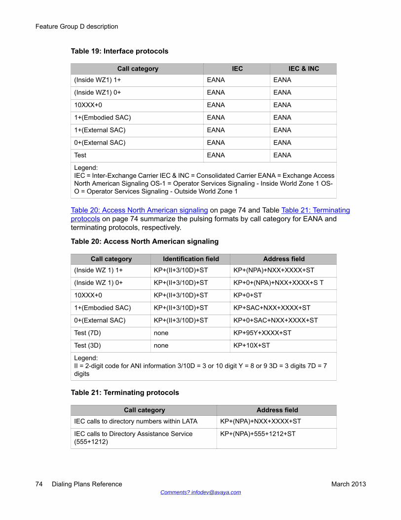
Table 19: Interface protocols
Call category IEC IEC & INC(Inside WZ1) 1+ EANA EANA
(Inside WZ1) 0+ EANA EANA
10XXX+0 EANA EANA
1+(Embodied SAC) EANA EANA
1+(External SAC) EANA EANA
0+(External SAC) EANA EANA
Test EANA EANA
Legend:IEC = Inter-Exchange Carrier IEC & INC = Consolidated Carrier EANA = Exchange AccessNorth American Signaling OS-1 = Operator Services Signaling - Inside World Zone 1 OS-O = Operator Services Signaling - Outside World Zone 1
Table 20: Access North American signaling on page 74 and Table Table 21: Terminatingprotocols on page 74 summarize the pulsing formats by call category for EANA andterminating protocols, respectively.
Table 20: Access North American signaling
Call category Identification field Address field(Inside WZ 1) 1+ KP+(II+3/10D)+ST KP+(NPA)+NXX+XXXX+ST
(Inside WZ 1) 0+ KP+(II+3/10D)+ST KP+0+(NPA)+NXX+XXXX+S T
10XXX+0 KP+(II+3/10D)+ST KP+0+ST
1+(Embodied SAC) KP+(II+3/10D)+ST KP+SAC+NXX+XXXX+ST
0+(External SAC) KP+(II+3/10D)+ST KP+0+SAC+NXX+XXXX+ST
Test (7D) none KP+95Y+XXXX+ST
Test (3D) none KP+10X+ST
Legend:II = 2-digit code for ANI information 3/10D = 3 or 10 digit Y = 8 or 9 3D = 3 digits 7D = 7digits
Table 21: Terminating protocols
Call category Address fieldIEC calls to directory numbers within LATA KP+(NPA)+NXX+XXXX+ST
IEC calls to Directory Assistance Service(555+1212)
KP+(NPA)+555+1212+ST
Feature Group D description
74 Dialing Plans Reference March 2013Comments? [email protected]

Call category Address fieldIEC calls to LEC Test Lines* KP+95Y+XXXX+ST - Y=8 or 9 or KP
+10X+ST
*End-office codes other than 95Y can be used with LEC test lines in some areas.
EANA protocol specifications
LEC-to-carrier pulsingThe format restrictions on the pulsing combinations for calls in the (Inside WZ 1) 1+ and (InsideWZ 1) 0+ categories are as follows:
Identification field Address fieldKP+(II+3/10D)+ST KP+(0)+7/10D+ST
The format restrictions on the pulsing combinations are as follows:
• The first digit in the identification field after KP is never 1.
• The start pulse at the end of the identification sequence is not primed.
• The 7/10 D in the address field conforms with the NANP.
VariationsWhen ANI is provided, the structure of the identification field is KP+(II+3/10D)+ST. Thevariations in the field are Information digits (II).
Table 22: Information digits (II) on page 75 is the default table that shows the digit pair defaultassignments.
Table 22: Information digits (II)
Information digits Explanation00 Regular line
01 4- and 8 - party
06 Hotel/Motel
07 Coin-less
EANA protocol specifications
Dialing Plans Reference March 2013 75

Information digits Explanation10 Test call
12–19 Cannot be assigned because of conflicts with 1NX used as firstdigits in international calls
20 Automatic Identification of Outward Dialing (AIOD) listeddirectory number sent
27 Coin
95 Test Call
Alternative arrangementsThe carrier may elect to receive ANI or not to receive ANI.
The ANI digits are the full 10-digit billing number, including the Number Plan Area (NPA), exceptwhen the calling line's billing number cannot be identified. When the calling line's billing numbercannot be obtained, a 3-digit NPA, associated with the originating end office, is sent.
Without ANI, the basic format of the pulsing stream received by the carrier is as follows:
• KP+ST+KP+(0)+7/10D+ST
The identification field without ANI is reduced to KP+ST. By eliminating ANI, the two informationdigits (II) are also eliminated.
Time limitsWink-start – The IEC returns the wink-start signal within 3.5 seconds (Carrier Switch Time[CSWT]) of the trunk seizure.
Wink-start guard – The end of the wink-start signal must not occur before 210 ms (CSWT) afterreceipt of the incoming seizure signal. The IEC must be prepared to receive MF pulses 35 msafter the end of the wink-start signal. The LEC waits for 50 ms (Bell Operating Company SwitchTime [BSWT]) after the end of the wink-start signal before initiating MF pulsing.
Acknowledgment wink – The IEC responds with the acknowledgment wink between 200 ms(CSWT) and 3.5 seconds (CSWT) after receipt of the complete address field. The IEC shouldnot attempt to use the talking path for communication with the calling customer before returningthe acknowledgment wink.
Answer – The IEC provides an on-hook state continuing for at least 250 ms (CSWT) betweenthe acknowledgment wink and the steady off-hook signal indicating called party answer.
Feature Group D description
76 Dialing Plans Reference March 2013Comments? [email protected]

EANA protocol exampleTable 23: EANA protocol: customer dials a World Zone 1 number on page 77 and Table 24:Terminating protocol: carrier call to an LEC test line on page 77 show examples of severaloriginating calls using Exchange Access North American (EANA) signaling protocol.
Table 23: EANA protocol: customer dials a World Zone 1 number
Situation Customer dials (10990)+(1)+815+NXX+XXXX Trunk group uses ExchangeAccess North American signaling protocol
Interface interactions
LEC POT Meridian 1
Customer dials all but last 4 digits
Seize---------->----------------------<------------ Wink
Identification field KP+00+212+555+XXXX+ST
---------->------------
Customer finishes dialing
Address field KP+815+NXX+XXXX+ST---------->----------------------<------------
Acknowledgmentwink
LEC connects talking path
----------<------------ Answer
Disconnect ---------->------------
----------<------------ Disconnect
InterpretationClass of service of calling line is Regular (II=00). Billing number of calling line is212+555+XXXX. Dial 0 calling service is not requested (1+call). Called number is 815+NXX+XXXX.
Terminating protocol exampleTable 24: Terminating protocol: carrier call to an LEC test line on page 77 shows an exampleof a call to an LEC test line using the FGD terminating protocol.
Table 24: Terminating protocol: carrier call to an LEC test line
Situation Carrier's craftsperson to connect to an LEC test line Trunk group uses terminatingsignaling protocol
EANA protocol specifications
Dialing Plans Reference March 2013 77
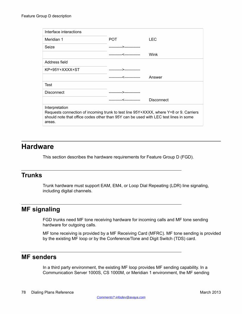
Interface interactions
Meridian 1 POT LEC
Seize ---------->------------
----------<------------ Wink
Address field
KP+95Y+XXXX+ST ---------->------------
----------<------------ Answer
Test
Disconnect ---------->------------
----------<------------ Disconnect
InterpretationRequests connection of incoming trunk to test line 95Y+XXXX, where Y=8 or 9. Carriersshould note that office codes other than 95Y can be used with LEC test lines in someareas.
HardwareThis section describes the hardware requirements for Feature Group D (FGD).
TrunksTrunk hardware must support EAM, EM4, or Loop Dial Repeating (LDR) line signaling,including digital channels.
MF signalingFGD trunks need MF tone receiving hardware for incoming calls and MF tone sendinghardware for outgoing calls.
MF tone receiving is provided by a MF Receiving Card (MFRC). MF tone sending is providedby the existing MF loop or by the Conference/Tone and Digit Switch (TDS) card.
MF sendersIn a third party environment, the existing MF loop provides MF sending capability. In aCommunication Server 1000S, CS 1000M, or Meridian 1 environment, the MF sending
Feature Group D description
78 Dialing Plans Reference March 2013Comments? [email protected]
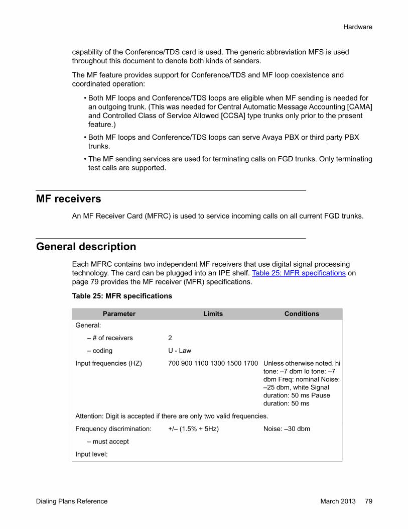
capability of the Conference/TDS card is used. The generic abbreviation MFS is usedthroughout this document to denote both kinds of senders.
The MF feature provides support for Conference/TDS and MF loop coexistence andcoordinated operation:
• Both MF loops and Conference/TDS loops are eligible when MF sending is needed foran outgoing trunk. (This was needed for Central Automatic Message Accounting [CAMA]and Controlled Class of Service Allowed [CCSA] type trunks only prior to the presentfeature.)
• Both MF loops and Conference/TDS loops can serve Avaya PBX or third party PBXtrunks.
• The MF sending services are used for terminating calls on FGD trunks. Only terminatingtest calls are supported.
MF receiversAn MF Receiver Card (MFRC) is used to service incoming calls on all current FGD trunks.
General descriptionEach MFRC contains two independent MF receivers that use digital signal processingtechnology. The card can be plugged into an IPE shelf. Table 25: MFR specifications onpage 79 provides the MF receiver (MFR) specifications.
Table 25: MFR specifications
Parameter Limits ConditionsGeneral:
– # of receivers 2
– coding U - Law
Input frequencies (HZ) 700 900 1100 1300 1500 1700 Unless otherwise noted. hitone: –7 dbm lo tone: –7dbm Freq: nominal Noise:–25 dbm, white Signalduration: 50 ms Pauseduration: 50 ms
Attention: Digit is accepted if there are only two valid frequencies.
Frequency discrimination: +/– (1.5% + 5Hz) Noise: –30 dbm
– must accept
Input level:
Hardware
Dialing Plans Reference March 2013 79

Parameter Limits Conditions–must accept–must reject
0 to –25 dbm per tonebelow –35 dbm per tone
Signal duration:
– must accept– must reject
>30 ms<10 ms
All signals except KP
– must accept (KP)– may accept (KP)– must reject (KP)
>55 ms>30 ms<10 ms
KP signalKP signalKP signal
Signal interruption
– ignore interruption <10 ms After minimum lengthsignal has been received
Time Shift between two frequencies:
– must accept <4 ms
Coincidence between the two frequencies:
– must reject <10 ms
Interdigit pause A pause means:
– must accept >25 ms signal <–35 dbm
Max dialing speed 10 digits per second
Tolerance to twist:
– must accept < 6 dbm One tone relative to theother tone.
Reception in presence of disturbances.
Attention: Digit is accepted if there are only two valid frequencies.
Error rate in presence of whitenoise
< 1/2500 calls Nominal freq: -23 dbm/tone On/Off = 50/50 msSignal to noise ratio = (–20 dbm all digits each call)( –10 digits)
Immunity to impulse noiseerror rate
< 1/2500 calls Nominal freq: –23 dbm/tone On/Off = 50/50 msSignal to noise ratio = –12dbm ATT Digit simulationtest tape #291m from pub.56201 Duration: 1 hour
Power lines:
– error rate < 1/2500 calls 60 Hz signal at –9 dbm or180 Hz signal at –22 dbm
Feature Group D description
80 Dialing Plans Reference March 2013Comments? [email protected]
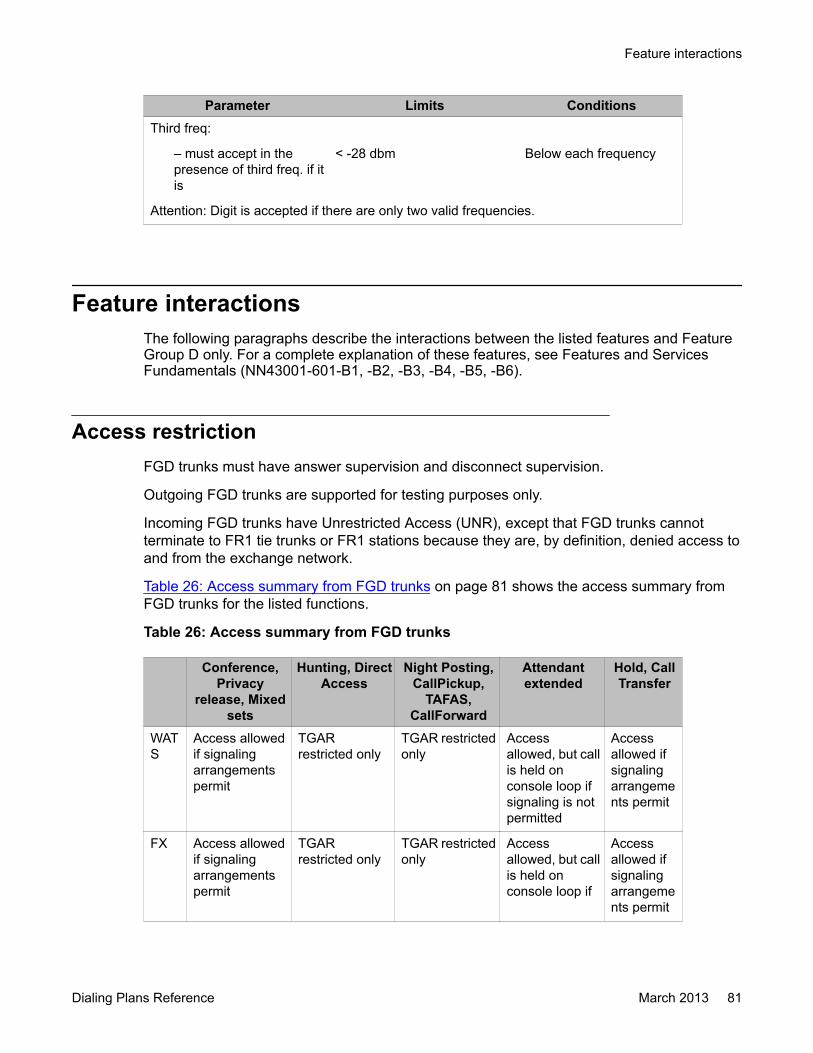
Parameter Limits ConditionsThird freq:
– must accept in thepresence of third freq. if itis
< -28 dbm Below each frequency
Attention: Digit is accepted if there are only two valid frequencies.
Feature interactionsThe following paragraphs describe the interactions between the listed features and FeatureGroup D only. For a complete explanation of these features, see Features and ServicesFundamentals (NN43001-601-B1, -B2, -B3, -B4, -B5, -B6).
Access restrictionFGD trunks must have answer supervision and disconnect supervision.
Outgoing FGD trunks are supported for testing purposes only.
Incoming FGD trunks have Unrestricted Access (UNR), except that FGD trunks cannotterminate to FR1 tie trunks or FR1 stations because they are, by definition, denied access toand from the exchange network.
Table 26: Access summary from FGD trunks on page 81 shows the access summary fromFGD trunks for the listed functions.
Table 26: Access summary from FGD trunks
Conference,Privacy
release, Mixedsets
Hunting, DirectAccess
Night Posting,CallPickup,
TAFAS,CallForward
Attendantextended
Hold, CallTransfer
WATS
Access allowedif signalingarrangementspermit
TGARrestricted only
TGAR restrictedonly
Accessallowed, but callis held onconsole loop ifsignaling is notpermitted
Accessallowed ifsignalingarrangements permit
FX Access allowedif signalingarrangementspermit
TGARrestricted only
TGAR restrictedonly
Accessallowed, but callis held onconsole loop if
Accessallowed ifsignalingarrangements permit
Feature interactions
Dialing Plans Reference March 2013 81
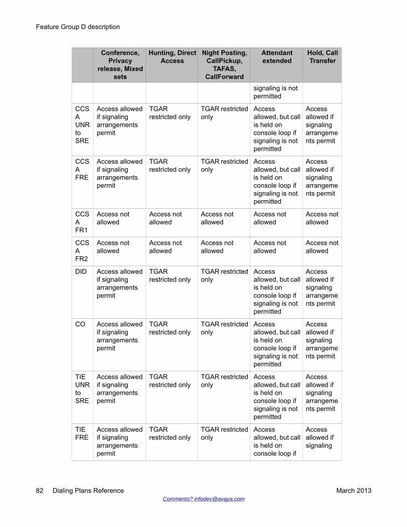
Conference,Privacy
release, Mixedsets
Hunting, DirectAccess
Night Posting,CallPickup,
TAFAS,CallForward
Attendantextended
Hold, CallTransfer
signaling is notpermitted
CCSAUNRtoSRE
Access allowedif signalingarrangementspermit
TGARrestricted only
TGAR restrictedonly
Accessallowed, but callis held onconsole loop ifsignaling is notpermitted
Accessallowed ifsignalingarrangements permit
CCSAFRE
Access allowedif signalingarrangementspermit
TGARrestricted only
TGAR restrictedonly
Accessallowed, but callis held onconsole loop ifsignaling is notpermitted
Accessallowed ifsignalingarrangements permit
CCSAFR1
Access notallowed
Access notallowed
Access notallowed
Access notallowed
Access notallowed
CCSAFR2
Access notallowed
Access notallowed
Access notallowed
Access notallowed
Access notallowed
DID Access allowedif signalingarrangementspermit
TGARrestricted only
TGAR restrictedonly
Accessallowed, but callis held onconsole loop ifsignaling is notpermitted
Accessallowed ifsignalingarrangements permit
CO Access allowedif signalingarrangementspermit
TGARrestricted only
TGAR restrictedonly
Accessallowed, but callis held onconsole loop ifsignaling is notpermitted
Accessallowed ifsignalingarrangements permit
TIEUNRtoSRE
Access allowedif signalingarrangementspermit
TGARrestricted only
TGAR restrictedonly
Accessallowed, but callis held onconsole loop ifsignaling is notpermitted
Accessallowed ifsignalingarrangements permit
TIEFRE
Access allowedif signalingarrangementspermit
TGARrestricted only
TGAR restrictedonly
Accessallowed, but callis held onconsole loop if
Accessallowed ifsignaling
Feature Group D description
82 Dialing Plans Reference March 2013Comments? [email protected]
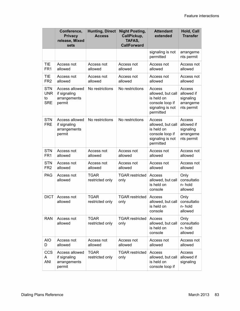
Conference,Privacy
release, Mixedsets
Hunting, DirectAccess
Night Posting,CallPickup,
TAFAS,CallForward
Attendantextended
Hold, CallTransfer
signaling is notpermitted
arrangements permit
TIEFR1
Access notallowed
Access notallowed
Access notallowed
Access notallowed
Access notallowed
TIEFR2
Access notallowed
Access notallowed
Access notallowed
Access notallowed
Access notallowed
STNUNRtoSRE
Access allowedif signalingarrangementspermit
No restrictions No restrictions Accessallowed, but callis held onconsole loop ifsignaling is notpermitted
Accessallowed ifsignalingarrangements permit
STNFRE
Access allowedif signalingarrangementspermit
No restrictions No restrictions Accessallowed, but callis held onconsole loop ifsignaling is notpermitted
Accessallowed ifsignalingarrangements permit
STNFR1
Access notallowed
Access notallowed
Access notallowed
Access notallowed
Access notallowed
STNFR2
Access notallowed
Access notallowed
Access notallowed
Access notallowed
Access notallowed
PAG Access notallowed
TGARrestricted only
TGAR restrictedonly
Accessallowed, but callis held onconsole
Onlyconsultation- holdallowed
DICT Access notallowed
TGARrestricted only
TGAR restrictedonly
Accessallowed, but callis held onconsole
Onlyconsultation- holdallowed
RAN Access notallowed
TGARrestricted only
TGAR restrictedonly
Accessallowed, but callis held onconsole
Onlyconsultation- holdallowed
AIOD
Access notallowed
Access notallowed
Access notallowed
Access notallowed
Access notallowed
CCSAANI
Access allowedif signalingarrangementspermit
TGARrestricted only
TGAR restrictedonly
Accessallowed, but callis held onconsole loop if
Accessallowed ifsignaling
Feature interactions
Dialing Plans Reference March 2013 83
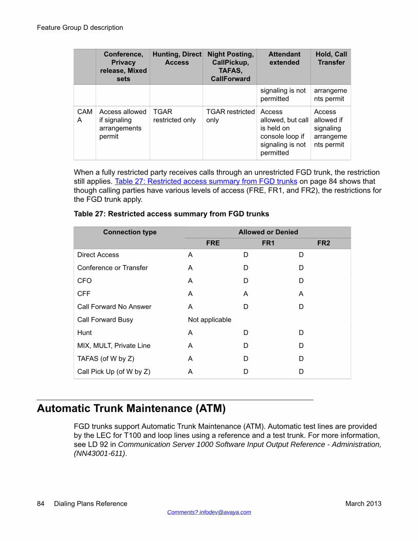
Conference,Privacy
release, Mixedsets
Hunting, DirectAccess
Night Posting,CallPickup,
TAFAS,CallForward
Attendantextended
Hold, CallTransfer
signaling is notpermitted
arrangements permit
CAMA
Access allowedif signalingarrangementspermit
TGARrestricted only
TGAR restrictedonly
Accessallowed, but callis held onconsole loop ifsignaling is notpermitted
Accessallowed ifsignalingarrangements permit
When a fully restricted party receives calls through an unrestricted FGD trunk, the restrictionstill applies. Table 27: Restricted access summary from FGD trunks on page 84 shows thatthough calling parties have various levels of access (FRE, FR1, and FR2), the restrictions forthe FGD trunk apply.
Table 27: Restricted access summary from FGD trunks
Connection type Allowed or DeniedFRE FR1 FR2
Direct Access A D D
Conference or Transfer A D D
CFO A D D
CFF A A A
Call Forward No Answer A D D
Call Forward Busy Not applicable
Hunt A D D
MIX, MULT, Private Line A D D
TAFAS (of W by Z) A D D
Call Pick Up (of W by Z) A D D
Automatic Trunk Maintenance (ATM)FGD trunks support Automatic Trunk Maintenance (ATM). Automatic test lines are providedby the LEC for T100 and loop lines using a reference and a test trunk. For more information,see LD 92 in Communication Server 1000 Software Input Output Reference - Administration,(NN43001-611).
Feature Group D description
84 Dialing Plans Reference March 2013Comments? [email protected]
Important:ATM is not supported on trunks controlled by a D-channel.
Barge-InBarge-In is not supported on an FGD trunk.
Call Detail Recording (CDR)The CDR records can contain ANI information. For a complete discussion, see Call DetailRecording Fundamentals (NN43001-550).
Calling Line ID (CLID)When an FGD call is routed over ISDN Primary Rate Interface (PRI) or Integrated ServicesLink (ISL), the complete 10-digit ANI number is provided as the CLID. Three-digit ANI numbersare not treated as CLID.
Call Party Disconnect Control (CPDC)On an incoming FGD route, Call Party Disconnect Control is allowed but not recommended.If CPDC = YES, any disconnect signal received from the LEC is ignored.
This does not apply to test calls.
Call Party Name Display (CPND)The name defined for the incoming FGD trunk access code is displayed.
Customer Controlled Routing (CCR)The ANI is used as the CLID when sent to the CCR processor for displaying the calling partynumber.
Feature interactions
Dialing Plans Reference March 2013 85
Dialed Number Identification Service (DNIS)The N digit DNIS modification changes the number of supported DNIS digits from one to sevento one to thirty-one. However, Feature group D will not support 31 digits DNIS. It supportsseven digits of DNIS information. To implement this change, customers must set the NDGTprompt in LD 16 to indicate the number of DNIS digits expected (1–7, with a default of 4).
For every incoming FGD call, the DNIS is saved. Normal FGD termination uses NARS to reachan Automatic Call Distribution Directory Number (ACD DN).
DNIS information can be displayed on a terminating telephone across call modification. If aDNIS trunk call originates from an FGD trunk and the terminating agent performs callmodifications within the same switch, the DNIS number appears on the terminating telephone.The number of DNIS digits that appear depends on the software release installed and thenumber of digit display available on the set. This capability applies to both ACD and non-ACDagents, and to such call modifications as Conference, Transfer, Call Park, and Call ParkRecall.
The DNIS number displays the last one to seven digits of the FGD address field.
If the DNIS-CDR option of the incoming FGD trunk's Route Data Block is enabled, the DNISnumber is appended to the end of the CDR record.
Call Detail Recording (CDR) supports the DNIS number for the FGD trunk. For moreinformation, see Call Detail Recording Fundamentals, (NN43001-550).
Digit DisplayFGD supports Digit Display where allowed.
If more than 16 digits (including delimiters) are displayed, the digits scroll to the left, deletingthe left-most digits from the display. The right-most 16 digits remain on the display.
Incoming Digit Conversion (IDC)Incoming Digit Conversion (IDC) is not supported on FGD trunks.
ISDN PRI and ISLFGD calls should use ISDN networking capability after a call has reached the network.
Feature Group D description
86 Dialing Plans Reference March 2013Comments? [email protected]

Network Alternate Route Selection (NARS)FGD relies on the NARS feature for call termination. NARS is enhanced by FGD to allow localtermination.
Network Call Redirection (NCRD)If an FGD call is redirected for any reason supported by NCRD, ANI is used for updating theterminating telephone's display.
Malicious Call Trace (MCT)A field added to the MCT record output contains the identification code (II+ANI) received fromthe LEC, thus identifying the caller. A second line is added to the MCT printout that lists aheader "ANI," the II, and the ANI digits. If no ANI digits are received, an unmodified MaliciousCall Trace (MCT) report is printed. An example of the MCT printout is shown below:
MCT CUST0 TN 117 3 10 4 *TN 109 3 10 2 15:30:05 12/11/91
ANI 00-2134159661
If an incomplete identification field is given, the printout includes all the digits received.
MCT CUST0 TN 117 3 10 4 *TN 109 3 10 2 15:30:05 12/11/91
ANI 00-213
Minor AlarmThe minor alarm on the attendant console lights up whenever one or more MFR units failstesting.
Private Line ServiceFGD trunks should not be defined as Private Lines.
Feature interactions
Dialing Plans Reference March 2013 87
Traffic measurementsSee Traffic Measurement Formats and Outputs Reference (NN43001-750) for a completedescription of the traffic measurement printouts.
Trunk Group Distinctive RingingTrunk Group Distinctive Ringing is supported by FGD trunks when DRNG = YES in the FGDdata block.
Trunk Verification from a Station (TVS)Telephones with Trunk Verification from a Station Allowed can access FGD trunks and use theMF capability to dial test numbers of three or seven digits. (Refer to Figure 9: Trunkverification on page 89.) There is usually no dial tone provided on FGD trunks.
Feature Group D description
88 Dialing Plans Reference March 2013Comments? [email protected]

Figure 9: Trunk verification
Feature interactions
Dialing Plans Reference March 2013 89
Chapter 8: Feature Group D operation
Navigation• Example: Using Feature Group D on page 91
• Incoming call processing on page 92
• Dial pulse dialing on FGD trunks on page 101
• Operating parameters on page 102
Example: Using Feature Group DThis section describes call direction. Incoming calls are calls from the Local Exchange Carrier(LEC) to the IEC (Communication Server 1000S, Avaya Communication Server 1000M, orMeridian 1), and outgoing calls are from the IEC to the LEC. Therefore, incoming calls are callscoming into the private network.
How to initiate a callPre-subscribed user – The case of a pre-subscribed user assumes prior arrangements havebeen made to use a specific long distance network or local telephone company (for exampleSPRINT, MCI, or the carrier being served by the Avaya PBX with Feature Group D [FGD]capability). When the user picks up a pre-subscribed home or work phone and dials a longdistance call in the normal way (for example, 1+area code+phone number), the LEC routesthat call to the pre-subscribed carrier for termination over that carrier's network.
Non-presubscribed user – In the case of a non-pre-subscribed user, the user dials a 5-digitcarrier access code (10XXX) before the address digits. This alerts the LEC that this particularcall should be routed to the requested long distance carrier for completion. SPRINT, MCI, AT&T,and others have carrier access codes that are recognized by all LECs.
Dialing Plans Reference March 2013 91

Incoming call processingCall processing of incoming FGD calls is designed to provide maximum flexibility in call routingto external or local DNs.
For call types other than three-digit test calls and operator calls, FGD uses the existing NARStranslation table(s). There are usually two translation tables if the NARS package is equipped:
• The first translation table contains routing and other information about NPAs.
• The second translation table contains similar information about NXXs in the home NPA.
NARS accesses these tables by using two different access codes: AC1 and AC2. However,there is no built-in constraint in relating AC1 (or AC2) to the NPA (or NXX) table.
The FGD database identifies the NARS access codes (AC1 or AC2) as being the LDAC (LongDistance Access Code—the one leading to the desired NPA translation table) or the LAAC(Local Area Access Code—the one leading to the NXX translation table).
If the Basic Alternate Route Selection (BARS) and not the NARS package is equipped, thenone translation table exists, and the LDAC and LAAC are identical. This could also be true ifthe NARS package is equipped but only one translation table is configured.
To convert the addressing information obtained from the FGD trunk into a digit sequence thatcan be processed by NARS, the FGD software prefixes the access code as either LDAC orLAAC.
Incoming FGD calls are processed as follows:
1. Digit collecting phase in which all incoming MF digits (ID field and address field) arecollected.
2. Address format validation that checks for valid NPA and NXX and checks that theaddress fields contain the correct number of digits.
NPA or NXX, with 2 <= N <= 9, P = 0 or P = 1, A or X = 0 to 9
An invalid address field leads to call interception, except for the cases in which toomany digits are received or no ST is received. In these cases, the MF receiver isreleased, the trunk is locked out, and no intercept occurs.
3. ANI field format validation
The call category determines whether the LEC provides the ANI data.
4. II (information digits) screening
The first two digits of the ID field are the II digits. A list of allowed II digits is containedin the FGD block. If the II digits are not defined, the call is intercepted and an errormessage is (optionally) issued.
Feature Group D operation
92 Dialing Plans Reference March 2013Comments? [email protected]

5. ANI screening (optional)
ANI digits are checked, and an NCOS is attached to the call. In the case of anundefined ANI, call interception can occur, and an error message can (optionally)be issued.
6. Address preparation
The address field is retrieved, and one of the NARS access codes is prefixed to it,to make the number conform to the existing Meridian 1 translation tables.
7. Translation and termination
The final address is processed by the existing NARS routing.
Local terminationIf the FGD call is to be routed to some other node in the network, the NARS feature can makethe conversion. The NARS access code is prefixed to the digits; some additional digitmanipulation also occurs.
However, the existing NARS feature is not capable of making the conversion if the callterminates on a DN in the local switch that serves as an interface to the LEC using FGD, andfull digit conversion (more than four digits) is required.
In this case, the Local Termination (LTER) entry in the NARS route list block is used for localtranslation, and is not related to any trunk group. The LTER entry may appear in any route listand can be accessed when route selection takes place. The existing restriction facilities, whichinclude TOD (Time-Of-Day schedule), FRL, and FCAS, can be applied as usual.
When an LTER entry is selected, NARS considers it a success, regardless of the result of thetermination (busy, vacant number). When the LTER entry is not restricted by the facilitiesmentioned above, the entries following it in the route list will never be selected.
Calls inside World Zone 1 (7 digits)These calls are characterized by an address field of seven digits. The Communication Server1000S, CS 1000M, or Meridian 1 inserts the NARS LAAC access code before the addressfield.
Calls inside World Zone 1 (10 digits)These calls are characterized by an address field of 10 digits. The Communication Server1000S, CS 1000M, or Meridian 1 inserts the NARS LDAC access code before the addressfield, thus allowing routing of the call within the corporate network.
Incoming call processing
Dialing Plans Reference March 2013 93

Calls inside World Zone 1 (0+ and 0-)A call to the operator is distinguished by a digit sequence in which the first digit of the addressfield is 0.
The address field dialed by the incoming FGD trunk should use one of the following sequences:
• 0+ type call: KP + 0 + (NPA) + NXX + XXXX + ST
• 0+ type call: KP + 0 + SAC + NXX + XXXX + ST
• 0- type call: KP + 0 + ST
An operator DN (or up to 16 digits) is defined through a Service Change (SCH) and all "0-" and"0+" calls are directed to this DN. This can be either the local attendant DN or any DN in thenetwork.
During call processing in the address preparation, the address field received from the FGDtrunk is replaced with the operator DN described above. The call is then processed by the DNtranslation tables.
An option is provided to intercept all "0+" and "0-" calls to a Recorded Announcement Trunkroute.
An address field sequence beginning with 0, but followed by an incorrect number of digits, orcontaining an invalid NPA, will lead to call intercept (invalid address format). In addition, therest of the address field that follows the "0" is ignored.
Table 28: EANA protocol: customer dials 10XXX+0 on page 94 provides an example of a"0+" call.
Table 28: EANA protocol: customer dials 10XXX+0
Situation Customer dials 10990+0 Trunk group uses Exchange Access North American(EANA) signaling protocol
Interface interactions
LEC POT Communication Server1000S, CS 1000M, orMeridian 1
Customer finishes dialing
Seize ---------->----------------------<------------ Wink
Identification fieldKP+0+212+555+XXXX+ST
---------->------------
Address FieldKP+0+ST
---------->-----------------------<------------ Acknowledgment wink
Feature Group D operation
94 Dialing Plans Reference March 2013Comments? [email protected]

LEC connects talking path
Disconnect----------<---------------------->----------------------<------------
AnswerDisconnect
InterpretationClass of service of calling line is regular (II=00). Billing number of calling line is212+555+XXXX. Customer did not provide a destination address.
Information digits screening for incoming callsThe FGD feature allows flexible II type assignment. Table 29: Information digits (II) onpage 95 shows the II digits defined as defaults. The interpretation of the various II codes(00–99) is defined by the customer through service changes. The flexibility is per route: thecustomer defines independent FGD blocks (up to 128) containing the II definitions, thenspecifies one block index for each FGD route. Each number in the 00–99 range can be definedas pertaining to one of the II-types listed in Table 29: Information digits (II) on page 95.Numbers in the 00–99 range that have not been defined are considered denied.
Table 29: Information digits (II)
Information digits Explanation00 Regular line
01 4- and 8 - party
06 Hotel/Motel
07 Coin-less
10 Test call
12–19 Not assigned because of conflicts with 1NX used asfirst digits in international calls
20 AIOD listed directory number sent
27 Coin
95 Test Call
Information digit pairs 10, 12–19, and 95 are not generated as ANI information digits by LECoriginating end offices.
Because the identification field precedes the address field for exchange access signaling, andbecause there is no identification field on test calls, the first two digits of the address field fortest calls appear to the carrier as ANI information digits. Either a 10 or a 95 in this position tellsthe carrier that the incoming call is a test call.
Digits 12 to 19 are used for calls outside World Zone 1. These are not used by EANA.
Incoming call processing
Dialing Plans Reference March 2013 95
In addition, an Network Class of Service (NCOS) number may be attached to an II. This allowsit to bypass ANI screening. If an II has an NCOS attached to it, then
• ANI screening will not be done on calls initiated by customers with II.
• The incoming FGD trunk will have the NCOS stated above.
In the II processing phase, the information related to the call type is retrieved from the FGDblock. If intercept treatment is needed (for the invalid II case), intercept treatment is applied asdefined for "invalid II."
FGD call interceptIntercept treatment is supplied for the following invalid calls:
• Invalid address field format
• Invalid II
• Invalid ANI
The intercept treatment for each of these calls can be defined by Service Change to beOverflow Tone (OVF), a Recorded Announcement (RAN), or termination on a network or localDN.
Incoming test calls (3 and 7 digits)The line testing facilities currently provided by the system to incoming trunks are:
• A 100 test termination DN for simultaneous access by up to four trunks. There is one 100test termination DN per customer.
• Four pairs of reference trunk termination DNs and test trunk termination DNs.
A test call digit sequence is a 3-digit or 7 - digit sequence of the form 10X (3 digits) or 95Y-XXXX (7 digits), where Y is either 8 or 9 (the 10 and 95 prefixes may be modified by servicechange). There is no identification field; therefore, digits 10 or 95 appear to the carrier as anII code (information digits). The processing after the II type has been identified as a test calltype is described below. Also refer to the section Information digits screening for incomingcalls on page 95.
In the FGD blocks, there are actually two types of test call information digits (II):
• TST3, typically digits 10
• TST7, typically digits 95
In the remainder of this section, reference may be made to either TST3 or TST7, or to theircorresponding digits 10 and 95.
Feature Group D operation
96 Dialing Plans Reference March 2013Comments? [email protected]
The two types of call information are treated differently:
• 10X calls are interpreted as calls to the T100-line test DN.
• 95Y calls are routed via NARS/BARS using the LAAC access code.
The possible situations are:
• Digits KP + 10X + ST are received on an incoming FGD trunk:
100 is dialed (X=0); it triggers the T100 line test. Normally an incoming tie dials the T100-line test DN. If X is not 0, the call receives an invalid address treatment.
Digit sequences starting with 10 but not containing three digits lead to call intercept (invalidaddress format).
• Digits KP + 95Y + XXXX + ST are received on an incoming FGD trunk.
The whole number is treated as an address: The LAAC access code is inserted, invokingNARS/BARS translation. The call can be forwarded to the network or handled by localtest equipment.
Digit sequences starting with 95 but not containing seven digits invoke a call intercept(invalid address format).
Authorization Code promptingFGD routes may be defined to prompt for Authorization Code.
An NCOS is attached to an incoming FGD trunk by one of the following:
• If ANI screening is bypassed, an NCOS is associated with the II type.
• If ANI screening is configured, an NCOS is defined by the ANI screening process.
• The NCOS of the call is the NCOS of the FGD trunk.
LEC trunk grouping and ANI provision by call category
LEC trunk grouping
Calls intended to terminate on an IEC POT can be assigned by the LEC to different trunk groups(for example, trunk routes) according to their category and the class of service (for example,II type) of the calling customer. Up to four such groups may exist.
The FGD block associated with an FGD trunk route contains data regarding the call categoriesexpected. A service change can modify this data to conform to the agreement between theLEC and the IEC. This data, together with the II screening data, serves to verify correct trunkgrouping as agreed to with the LEC.
Incoming call processing
Dialing Plans Reference March 2013 97
The appropriate error message is issued when a call of an unexpected category reaches theIEC. Table 18: Call categories on page 73 contains a list of call categories.
An IEC switch cannot distinguish between the following two categories:
• Embodied SAC calls
• External SAC calls
If one of them is expected, all SAC calls are considered expected. Test calls are consideredexpected.
ANI provisions
ANI digits are provided by the LEC based on call category according to the agreement withthe IEC.
The FGD block associated with an FGD trunk route determines whether ANI data is to bereceived on such a call.
Important:ANI data is never received on test calls.
An error message is issued when
• ANI is not received on a call when expected.
• ANI is received on a call when not expected.
ANI digits screening
This section describes the screening function to be performed on the ANI digits in anidentification field.
After the complete digit string (both identification and address fields) is collected, and the callpasses the II (information digits) screening, the ANI bypass option is attached to the call'sinformation digits.
If ANI screening is not configured, the call proceeds with the NCOS of the incoming trunk.Otherwise, the following ANI screening is performed.
If the ANI provision is selected by the IEC, the ANI digits are normally 10 digits (or three digitswhen the calling party cannot be identified).
• NPA+NXX+XXXX (normal case)• NPA (calling party not identified)
Calls with associated ANI digits from FGD trunks are screened against the ANI database asdefined in the access node.
Feature Group D operation
98 Dialing Plans Reference March 2013Comments? [email protected]

For each allowed (or recognized) NPA, ANI screening is defined in three levels:
• NPA (3 digits)• NPA+NXX (6 digits)• NPA+NXX+XXXX (10 digits)
Each valid ANI is associated with a specific NCOS, which is the calling party's initial NCOS,to be used for determining call termination through Electronic Switched Network (ESN).
10 ANI digits
If the 10 ANI digits (NPA+NXX+XXXX) are received from an incoming FGD trunk, call validationis based on the screening level defined in the ANI database:
• NPA (3 digits) screening level
The received ANI digits NPA must match a defined area code in the database.
• NPA+NXX (6 digits) screening level
The received ANI digits NXX must be within the defined end office number range underthe NPA.
• NPA+NXX+XXXX (10 digits) screening level
The received ANI digits XXXX must be within the defined subscriber number range underthe NPA+NXX.
A match yields an NCOS to be used later for called number screening and routing.Otherwise, invalid ANI treatment is applied.
Partial ANI digits
If only three ANI digits (NPA) are received from an incoming FGD trunk and:
• The NPA is defined in the ANI database (regardless of the screening level defined):
- 3-digit ANI allowed—Pass: extract the specified NCOS.
- 3-digit ANI not allowed—Fail: apply invalid ANI treatment.
• The NPA is not defined in the ANI database—Fail: apply invalid ANI treatment.
Invalid ANI treatment
Possible invalid ANI treatments include routing to Overflow Tone (OVF), RecordedAnnouncement (RAN), or a network or local DN or considering it as passed and mapping it toan NCOS that is specified for invalid ANI.
Incoming call processing
Dialing Plans Reference March 2013 99
ANI digits as Calling Line ID (CLID)
If an incoming FGD call is routed to a neighboring switch via an ISDN PRI or ISL, the complete10-digit ANI is used as the Calling Line ID (CLID). It is then sent (in a SETUP message) to theneighboring switch for CLID display. An incomplete 3-digit ANI is not treated as a CLID.
If the SHAN field of the FGD data block associated with the incoming route indicates that theANI should not be displayed on the terminating telephone, the ANI is still sent over the ISDNPRI or ISL as the CLID. However, the presentation indicator field of the calling party numberinformation element is set to presentation restricted, so the CLID is not displayed on theterminating telephone.
ANI display
For FGD calls terminating in the local switch, the received ANI number is displayed instead ofthe route access code and member number as is currently displayed for a trunk call. The optionis per FGD block.
The implementation of this capability does not modify the operation of the existing Digit Displayfeature.
The formats of the received ANI number are:
• KP + II + 10 + ST. The display is the 10-digit string.
• KP + II + 3D + ST. The display is the route access code and member number.
• KP + ST (no ANI). The display is the route access code and member number.
The rules and limitations of the Digit Display feature are used.
The ANI display for FGD has the same format and interactions with other features as the CLIDdisplay of an E.163 number (as opposed to a private network number).
ANI number display devices
The following devices support ANI number display:
• M2317
• M2006, M2008, and M2016S
• M2216ACD-1 and M2216ACD-2
• M2616
Feature Group D operation
100 Dialing Plans Reference March 2013Comments? [email protected]
Dial pulse dialing on FGD trunksDial Pulse (DP) outpulsing on trunks is not allowed on either incoming or outgoing FGDTtrunks.
Outgoing test callsOutgoing test calls are generated by:
• dialing the FGD route access code from a station and a test number consisting of threeor seven digits
• dialing the TVS access sequence from a station to select a specific FGD trunk. Forexample, dial a special prefix DN, plus the Trunk Verification from a Station (TVS) specialfunction code, plus the route access code, plus the trunk member number, and a testnumber (three or seven digits)
• dialing automatically from the Automatic Trunk Maintenance overlay (test numbers mustcontain either three or seven digits)
CDR recordsThe CDR records for calls in which an incoming FGD trunk was involved can (optionally)include an ANI digits field. The option is per route, defined in its FGD block. To include the ANIdigits field requires the Call Detail Recording Expansion (CDRE) package.
For a detailed discussion of CDR output, see Call Detail Recording Fundamentals(NN43001-550).
Transmission characteristicsFor the purposes of transmission losses and gains, FGD trunks are treated as tie trunks: analogFGD trunks have PTYP = ATT (port type in LD 16) and digital FGD trunks have PTYP = DTT.These values are imposed by Service Change when defining an FGDT route. In a connectionbetween an analog FGDT trunk and a PRI channel, the PRI channel is treated as a digital tie(DTT), overriding the definition for PRI channels.
Dial pulse dialing on FGD trunks
Dialing Plans Reference March 2013 101
Operating parameters
ParametersThe maximum number of Multifrequency Receivers (MFRs) that can be defined in a system is255.
The maximum number of FGD blocks that can be defined in a system is 128.
An FGD route can be configured as a DNIS route. In this situation, the route should carry ACDcalls only.
FGD trunks will use MF signaling only to establish a call. Dual Tone Multifrequency (DTMF)signaling can be used for in-band signaling after establishing an end-to-end connection. Forexample, it can be used for Authorization Code entry.
Terminating protocol is limited to test calls only.
FGD is available on all machine types. However, the available Protected Data Store (PDS)and disk storage is limited to the maximum amount of FGD data, particularly ANI data, thatcan be configured for a given machine type.
The linear and cyclic search methods are acceptable for FGD trunks.
MF Receiver guidelinesThe MF Receiver (MFR) receives 26 MF digits from the Equal Access End Office. Holding timefor the MF Receiver is estimated at 13 seconds (about 0.5 seconds per digit). When the numberof MF trunks are known, the following procedures can be used to estimate the MFRrequirements:
• Calculate the number of FGD calls from MF trunks. For example, with 30 CCS per trunkand 180 seconds holding time assumed:
FGD calls (FGDC) = # of MF trunks * 30 * 100/180 = 16.67 * # of MF trunks
• Calculate MFR traffic. For example, with 13 seconds receiver holding time assumed:
MFR traffic in CCS = FGDC * 13/100
Refer to Table 30: Multifrequency receiver load capacity: 6 to 15 second holding time onpage 103, Table 31: Multifrequency receiver load capacity: 16 to 25 second holding time onpage 104, and Table 32: Multifrequency receiver requirements: Poisson 0.1 percentblocking on page 106 to determine the number of MFRs to support your system.
Feature Group D operation
102 Dialing Plans Reference March 2013Comments? [email protected]

Table 30: Multifrequency receiver load capacity: 6 to 15 second holding time on page 103provides information on Multifrequency receiver load capacity with 6 to 15 second holdingtimes.
Table 30: Multifrequency receiver load capacity: 6 to 15 second holding time
Average holdingtime in seconds
6 7 8 9 10 11 12 13 14 15
Number of MFR
1 0 0 0 0 0 0 0 0 0 0
2 3 2 2 2 2 2 2 2 2 2
3 11 10 10 9 9 9 9 8 8 8
4 24 23 22 21 20 19 19 19 18 18
5 41 39 37 36 35 34 33 33 32 32
6 61 57 55 53 52 50 49 49 48 47
7 83 78 75 73 71 69 68 67 66 65
8 106 101 91 94 91 89 88 86 85 84
9 131 125 120 116 113 111 109 107 106 104
10 157 150 144 140 136 133 131 129 127 126
11 185 176 170 165 161 157 155 152 150 148
12 212 203 196 190 185 182 178 176 173 171
13 241 231 223 216 211 207 203 200 198 196
14 270 259 250 243 237 233 229 225 223 220
15 300 228 278 271 264 259 255 251 248 245
16 339 317 397 298 292 286 282 278 274 271
17 361 346 335 327 310 313 319 306 392 298
18 391 377 365 356 348 342 336 331 327 324
19 422 409 396 386 378 371 364 359 355 351
20 454 438 425 414 405 398 393 388 383 379
21 1487 469 455 444 435 427 420 415 410 406
22 517 501 487 475 466 456 449 443 438 434
23 550 531 516 504 494 487 479 472 467 562
24 583 563 547 535 524 515 509 502 497 491
25 615 595 579 566 555 545 537 532 526 521
26 647 628 612 598 586 576 567 560 554 548
Operating parameters
Dialing Plans Reference March 2013 103

Average holdingtime in seconds
6 7 8 9 10 11 12 13 14 15
27 680 659 642 628 618 607 597 589 583 577
28 714 691 674 659 647 638 628 620 613 607
29 746 724 706 690 678 667 659 651 644 637
30 779 758 738 723 709 698 690 682 674 668
31 813 792 771 755 742 729 719 710 703 696
32 847 822 805 788 774 761 750 741 733 726
33 882 855 835 818 804 793 781 772 763 756
34 913 889 868 850 836 825 812 803 795 787
35 947 923 900 883 867 855 844 835 826 818
36 981 957 934 916 900 886 876 866 857 850
37 1016 989 967 949 933 919 909 898 889 881
38 1051 1022 1001 982 966 951 938 928 918 912
39 1083 1055 1035 1015 999 984 970 959 949 941
40 1117 1089 1066 1046 1029 1017 1002 990 981 972
Attention: Load capacity is measure in CCS.
Table 31: Multifrequency receiver load capacity: 16 to 25 second holding time on page 104provides information on the Multifrequency receiver load capacity with 16 to 25 second holdingtimes.
Table 31: Multifrequency receiver load capacity: 16 to 25 second holding time
Average holding time inseconds
16 17 18 19 20 21 22 23 24 25
Number of MFR
1 0 0 0 0 0 0 0 0 0 0
2 2 2 2 2 2 2 2 2 2 2
3 8 8 8 8 8 8 8 8 8 8
4 18 18 18 18 18 17 17 17 17 17
5 31 31 31 30 30 30 30 30 30 29
6 47 46 46 45 45 45 45 44 44 44
7 64 63 63 62 62 62 61 61 61 60
8 83 82 82 81 80 80 79 79 79 78
9 103 102 101 100 100 99 99 98 98 97
Feature Group D operation
104 Dialing Plans Reference March 2013Comments? [email protected]
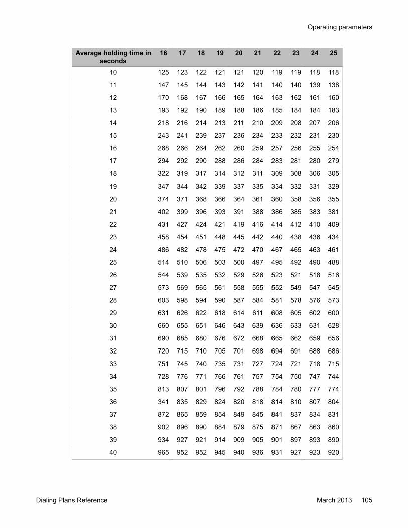
Average holding time inseconds
16 17 18 19 20 21 22 23 24 25
10 125 123 122 121 121 120 119 119 118 118
11 147 145 144 143 142 141 140 140 139 138
12 170 168 167 166 165 164 163 162 161 160
13 193 192 190 189 188 186 185 184 184 183
14 218 216 214 213 211 210 209 208 207 206
15 243 241 239 237 236 234 233 232 231 230
16 268 266 264 262 260 259 257 256 255 254
17 294 292 290 288 286 284 283 281 280 279
18 322 319 317 314 312 311 309 308 306 305
19 347 344 342 339 337 335 334 332 331 329
20 374 371 368 366 364 361 360 358 356 355
21 402 399 396 393 391 388 386 385 383 381
22 431 427 424 421 419 416 414 412 410 409
23 458 454 451 448 445 442 440 438 436 434
24 486 482 478 475 472 470 467 465 463 461
25 514 510 506 503 500 497 495 492 490 488
26 544 539 535 532 529 526 523 521 518 516
27 573 569 565 561 558 555 552 549 547 545
28 603 598 594 590 587 584 581 578 576 573
29 631 626 622 618 614 611 608 605 602 600
30 660 655 651 646 643 639 636 633 631 628
31 690 685 680 676 672 668 665 662 659 656
32 720 715 710 705 701 698 694 691 688 686
33 751 745 740 735 731 727 724 721 718 715
34 728 776 771 766 761 757 754 750 747 744
35 813 807 801 796 792 788 784 780 777 774
36 341 835 829 824 820 818 814 810 807 804
37 872 865 859 854 849 845 841 837 834 831
38 902 896 890 884 879 875 871 867 863 860
39 934 927 921 914 909 905 901 897 893 890
40 965 952 952 945 940 936 931 927 923 920
Operating parameters
Dialing Plans Reference March 2013 105

Average holding time inseconds
16 17 18 19 20 21 22 23 24 25
Attention: Load capacity is measured in CCS.
Table 32: Multifrequency receiver requirements: Poisson 0.1 percent blocking on page 106provides the Multifrequency receiver requirements with the Poisson 0.1 percent blockinginformation.
Table 32: Multifrequency receiver requirements: Poisson 0.1 percent blocking
Number ofMFR
MFR load(CCS)
Number ofMFR
MFR load(CCS)
Number ofMFR
MFR load(CCS)
1 0 18 276 35 703
2 2 19 299 36 729
3 7 20 323 37 756
4 15 21 346 38 783
5 27 22 370 39 810
6 40 23 395 40 837
7 55 24 419 41 865
8 71 25 444 42 892
9 88 26 469 43 919
10 107 27 495 44 947
11 126 28 520 45 975
12 145 29 545 46 1003
13 165 30 571 47 1030
14 187 31 597 48 1058
15 208 32 624 49 1086
16 231 33 650 50 1115
17 253 34 676
Feature Group D operation
106 Dialing Plans Reference March 2013Comments? [email protected]
Chapter 9: Feature Group D implementation
Navigation• Engineering guidelines on page 107
Engineering guidelinesWhen you estimate the total number of call registers required by the system (NCR in LD 17),consider the following points:
• An incoming FGD call uses one additional call register for the whole duration of the call.• An outgoing FGD call uses one additional call register for the outpulsing stage only
(including the subscriber's dialing).Because the FGD block is per system, the RAN route number(s) and/or network or local DNsgiven in response to prompts OPER, ADFT, IIT, and ANIT (in LD 19) are not associated withany customer. All customers using the FGD feature must define their RAN routes and/or DNsin accordance with FGD block definitions.
The following Service Change (SCH) information shows how to configure FGD capabilities onthe system. The loads shown here are only partial, and apply to FGD only. Only new promptsor prompts and responses required for FGD are shown here.
For a complete description of the service change prompts and responses, see AvayaCommunication Server 1000 Software Input Output Reference - Administration,NN43001-611.
Table 33: LD 13 : Digitone Receiver and Tone Detector.
Prompt Response DescriptionREQ NEW CHG Add or Change
TYPE MFR Multifrequency receivers A maximum of 255 MFRunits can be defined.
TN Terminal number
Dialing Plans Reference March 2013 107
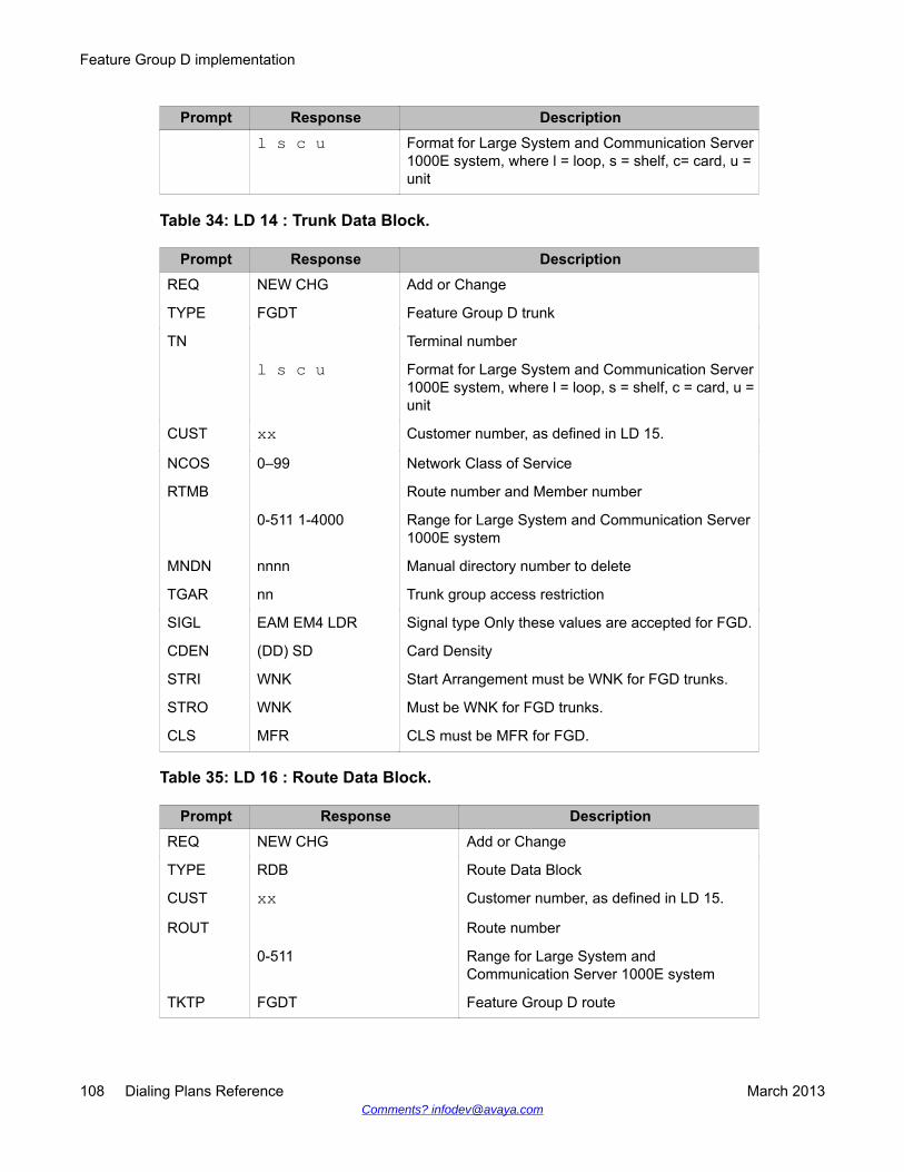
Prompt Response Descriptionl s c u Format for Large System and Communication Server
1000E system, where l = loop, s = shelf, c= card, u =unit
Table 34: LD 14 : Trunk Data Block.
Prompt Response DescriptionREQ NEW CHG Add or Change
TYPE FGDT Feature Group D trunk
TN Terminal number
l s c u Format for Large System and Communication Server1000E system, where l = loop, s = shelf, c = card, u =unit
CUST xx Customer number, as defined in LD 15.
NCOS 0–99 Network Class of Service
RTMB Route number and Member number
0-511 1-4000 Range for Large System and Communication Server1000E system
MNDN nnnn Manual directory number to delete
TGAR nn Trunk group access restriction
SIGL EAM EM4 LDR Signal type Only these values are accepted for FGD.
CDEN (DD) SD Card Density
STRI WNK Start Arrangement must be WNK for FGD trunks.
STRO WNK Must be WNK for FGD trunks.
CLS MFR CLS must be MFR for FGD.
Table 35: LD 16 : Route Data Block.
Prompt Response DescriptionREQ NEW CHG Add or Change
TYPE RDB Route Data Block
CUST xx Customer number, as defined in LD 15.
ROUT Route number
0-511 Range for Large System andCommunication Server 1000E system
TKTP FGDT Feature Group D route
Feature Group D implementation
108 Dialing Plans Reference March 2013Comments? [email protected]
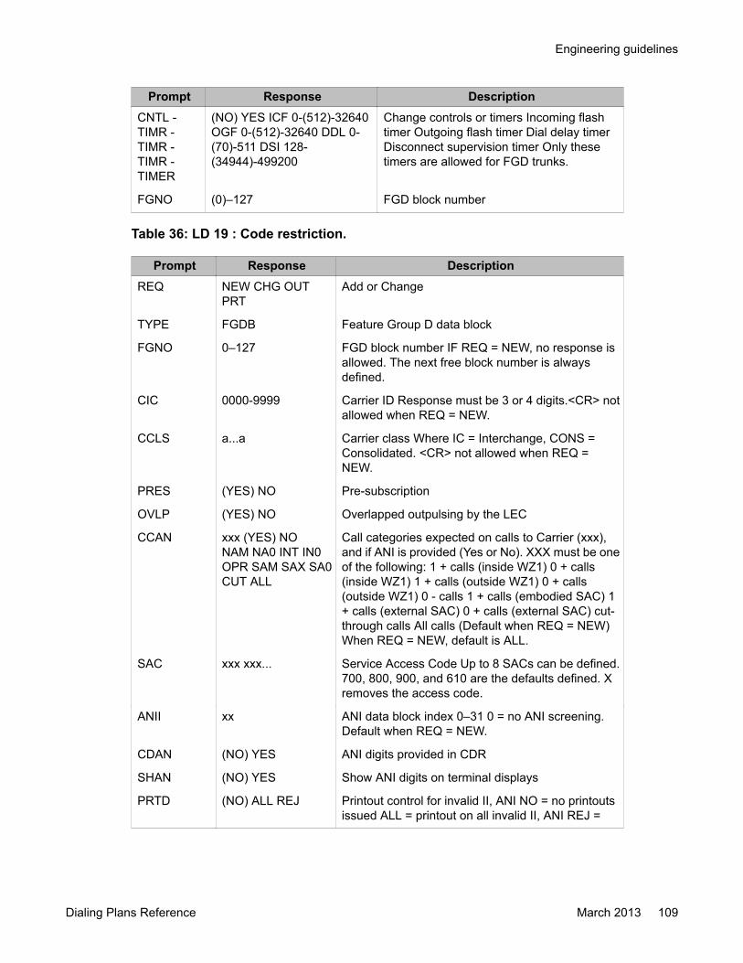
Prompt Response DescriptionCNTL -TIMR -TIMR -TIMR -TIMER
(NO) YES ICF 0-(512)-32640OGF 0-(512)-32640 DDL 0-(70)-511 DSI 128-(34944)-499200
Change controls or timers Incoming flashtimer Outgoing flash timer Dial delay timerDisconnect supervision timer Only thesetimers are allowed for FGD trunks.
FGNO (0)–127 FGD block number
Table 36: LD 19 : Code restriction.
Prompt Response DescriptionREQ NEW CHG OUT
PRTAdd or Change
TYPE FGDB Feature Group D data block
FGNO 0–127 FGD block number IF REQ = NEW, no response isallowed. The next free block number is alwaysdefined.
CIC 0000-9999 Carrier ID Response must be 3 or 4 digits.<CR> notallowed when REQ = NEW.
CCLS a...a Carrier class Where IC = Interchange, CONS =Consolidated. <CR> not allowed when REQ =NEW.
PRES (YES) NO Pre-subscription
OVLP (YES) NO Overlapped outpulsing by the LEC
CCAN xxx (YES) NONAM NA0 INT IN0OPR SAM SAX SA0CUT ALL
Call categories expected on calls to Carrier (xxx),and if ANI is provided (Yes or No). XXX must be oneof the following: 1 + calls (inside WZ1) 0 + calls(inside WZ1) 1 + calls (outside WZ1) 0 + calls(outside WZ1) 0 - calls 1 + calls (embodied SAC) 1+ calls (external SAC) 0 + calls (external SAC) cut-through calls All calls (Default when REQ = NEW)When REQ = NEW, default is ALL.
SAC xxx xxx... Service Access Code Up to 8 SACs can be defined.700, 800, 900, and 610 are the defaults defined. Xremoves the access code.
ANII xx ANI data block index 0–31 0 = no ANI screening.Default when REQ = NEW.
CDAN (NO) YES ANI digits provided in CDR
SHAN (NO) YES Show ANI digits on terminal displays
PRTD (NO) ALL REJ Printout control for invalid II, ANI NO = no printoutsissued ALL = printout on all invalid II, ANI REJ =
Engineering guidelines
Dialing Plans Reference March 2013 109

Prompt Response Descriptionprintout on all invalid II, but no printout for invalid ANIif ANI screening assigned an NCOS to the call
LDAC AC1, AC2 Long Distance Access Code Only if NARS isequipped
LAAC AC1, AC2 Local Area Access Code Only if NARS is equipped
OPER Treatment for 0+, 0- calls 1–16 digit network or localDN RAN route (0-511)
DN xxxx.. xx RANxxx
INTR (NO) YES Intercept treatment specified
-ADFT (OVF) RAN xxx DNxxx.. xx
for invalid address format (overflow, RAN, or local ornetwork DN)
-IIT (OVF) RAN xxx DNxxx.. XX
for invalid IIs (overflow, RAN, or local or network DN)
IITP xx yyyy zz Valid II, II type, and NCOS for ANI screening XX isan II range 00-99 YYYY must be one of the following:
REGU 4A8P HOTLCLES TST3 AIODCOIN TST7
Regular II 4 and 8 party II Hotel/Motel II Coinless IITest3 II AIOD II Coin II Test7 II ZZ is an optionalNCOS number defining ANI screening bypass range00–99. ANI screening bypass defaults to "NO" if anNCOS is not entered.
CPAR (NO) YES Call Processing parameters
CPAR (NO) YES Call Processing parameters
-INIT 0-(7)-9 Length of initial string of dialed digits on outgoingcalls (enbloc dialing)
-ENBS 1-(12)-30 Long enbloc dialing timeout (before initial string iscomplete) in seconds
-ENBS 1-(5)-30 Short enbloc dialing timeout (after initial string iscomplete) in seconds
-IFTO 2-(120)-255 Inter FGD field timeout (max time between two FGDfields) in seconds
-DGTO 128-(640)-5000 Inter digit timeout (max time between two FGD digitsin same field) in Msec
-MONT 0-(256)-2048 Minimum on hook time (min time betweenacknowledgment wink and answer off hook signal) inMsec
REQ NEW, CHG, OUT,PRT
Create, Change, Remove or Print
Feature Group D implementation
110 Dialing Plans Reference March 2013Comments? [email protected]
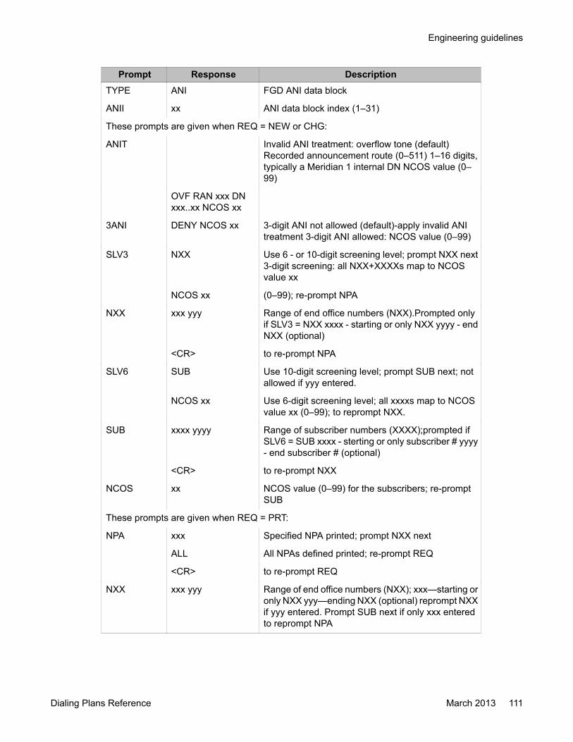
Prompt Response DescriptionTYPE ANI FGD ANI data block
ANII xx ANI data block index (1–31)
These prompts are given when REQ = NEW or CHG:
ANIT Invalid ANI treatment: overflow tone (default)Recorded announcement route (0–511) 1–16 digits,typically a Meridian 1 internal DN NCOS value (0–99)
OVF RAN xxx DNxxx..xx NCOS xx
3ANI DENY NCOS xx 3-digit ANI not allowed (default)-apply invalid ANItreatment 3-digit ANI allowed: NCOS value (0–99)
SLV3 NXX Use 6 - or 10-digit screening level; prompt NXX next3-digit screening: all NXX+XXXXs map to NCOSvalue xx
NCOS xx (0–99); re-prompt NPA
NXX xxx yyy Range of end office numbers (NXX).Prompted onlyif SLV3 = NXX xxxx - starting or only NXX yyyy - endNXX (optional)
<CR> to re-prompt NPA
SLV6 SUB Use 10-digit screening level; prompt SUB next; notallowed if yyy entered.
NCOS xx Use 6-digit screening level; all xxxxs map to NCOSvalue xx (0–99); to reprompt NXX.
SUB xxxx yyyy Range of subscriber numbers (XXXX);prompted ifSLV6 = SUB xxxx - sterting or only subscriber # yyyy- end subscriber # (optional)
<CR> to re-prompt NXX
NCOS xx NCOS value (0–99) for the subscribers; re-promptSUB
These prompts are given when REQ = PRT:
NPA xxx Specified NPA printed; prompt NXX next
ALL All NPAs defined printed; re-prompt REQ
<CR> to re-prompt REQ
NXX xxx yyy Range of end office numbers (NXX); xxx—starting oronly NXX yyy—ending NXX (optional) reprompt NXXif yyy entered. Prompt SUB next if only xxx enteredto reprompt NPA
Engineering guidelines
Dialing Plans Reference March 2013 111
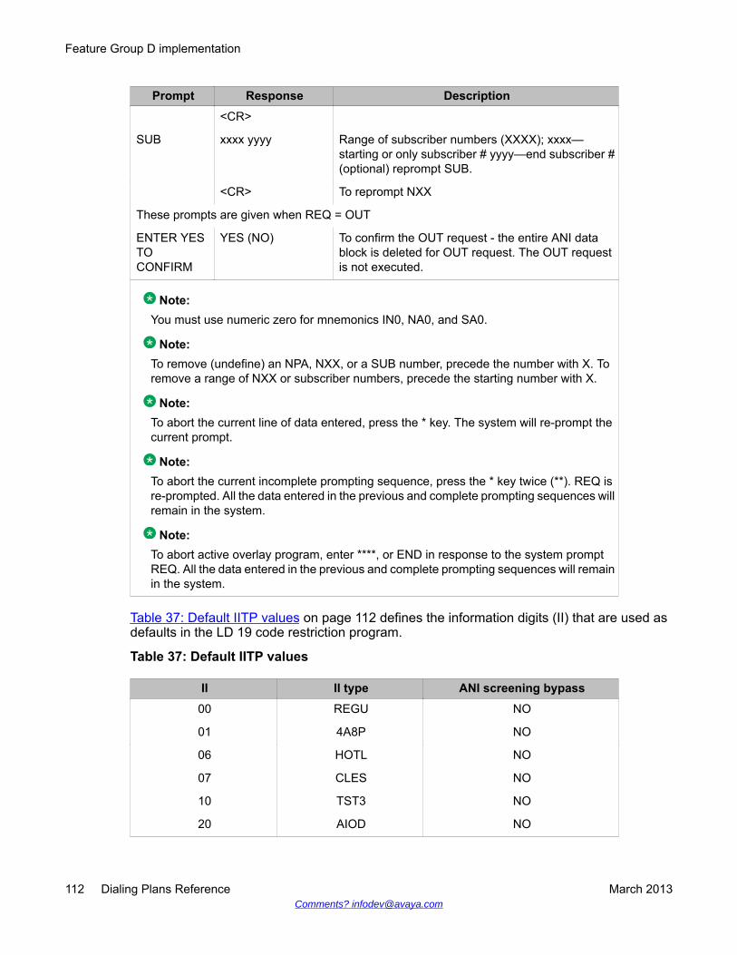
Prompt Response Description<CR>
SUB xxxx yyyy Range of subscriber numbers (XXXX); xxxx—starting or only subscriber # yyyy—end subscriber #(optional) reprompt SUB.
<CR> To reprompt NXX
These prompts are given when REQ = OUT
ENTER YESTOCONFIRM
YES (NO) To confirm the OUT request - the entire ANI datablock is deleted for OUT request. The OUT requestis not executed.
Note:You must use numeric zero for mnemonics IN0, NA0, and SA0.
Note:To remove (undefine) an NPA, NXX, or a SUB number, precede the number with X. Toremove a range of NXX or subscriber numbers, precede the starting number with X.
Note:To abort the current line of data entered, press the * key. The system will re-prompt thecurrent prompt.
Note:To abort the current incomplete prompting sequence, press the * key twice (**). REQ isre-prompted. All the data entered in the previous and complete prompting sequences willremain in the system.
Note:To abort active overlay program, enter ****, or END in response to the system promptREQ. All the data entered in the previous and complete prompting sequences will remainin the system.
Table 37: Default IITP values on page 112 defines the information digits (II) that are used asdefaults in the LD 19 code restriction program.
Table 37: Default IITP values
II II type ANI screening bypass00 REGU NO
01 4A8P NO
06 HOTL NO
07 CLES NO
10 TST3 NO
20 AIOD NO
Feature Group D implementation
112 Dialing Plans Reference March 2013Comments? [email protected]

II II type ANI screening bypass27 COIN NO
95 TST7 NO
Table 38: LD 20 : Print Routine.
Prompt Response DescriptionREQ PRT Print
TYPE TNB FGD MFR Includes FGD trunks and MFRs Print FGDtrunks Print Multifrequency units
TN Terminal number
l s c u Format for Large System andCommunication Server 1000E system,where l = loop, s = shelf, c = card, u = unit
LD 21 : Print routineThis print routine is modified to print FGDT route data blocks as defined using LD 16.
LD 22 : Print routine"FGD" is printed if package 158 is equipped.
Table 39: LD 29 : Memory Management.
Prompt Response DescriptionREQ ADD Add or Change
TYNM MFRR 1–255 FGD xxx yyy Number of Multifrequency receivers FGDdata blocks xxx = FGD data blocks (1–128)yyy = average number of II entries
ANI xxx yyyy zzzzz FGD ANI blocks xxx = number NPAs (1–160)yyyy = number of NXXs (0–9999) zzzzz =number XXXXs (0–30 000)
Changes are made to LD 86 to allow for definition and a print out of a new type of Route ListEntry, which is the Local Termination (LTER) entry. The prompts and responses are listedbelow.
Engineering guidelines
Dialing Plans Reference March 2013 113
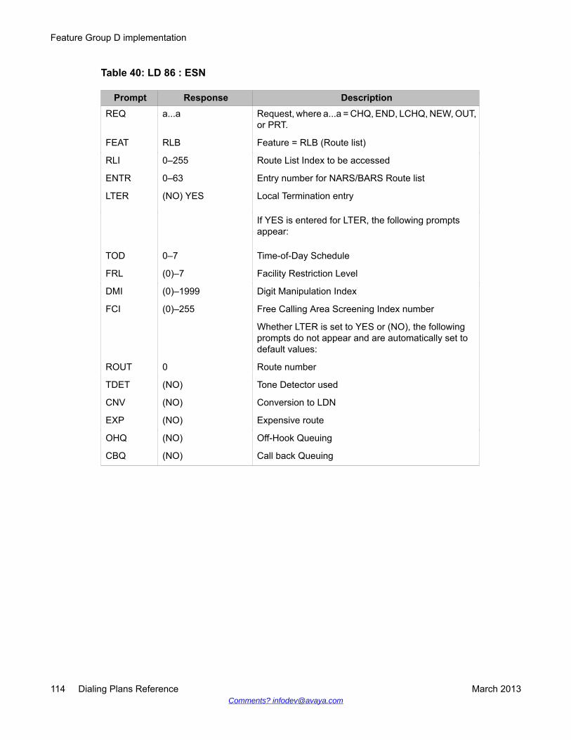
Table 40: LD 86 : ESN
Prompt Response DescriptionREQ a...a Request, where a...a = CHQ, END, LCHQ, NEW, OUT,
or PRT.
FEAT RLB Feature = RLB (Route list)
RLI 0–255 Route List Index to be accessed
ENTR 0–63 Entry number for NARS/BARS Route list
LTER (NO) YES Local Termination entry
If YES is entered for LTER, the following promptsappear:
TOD 0–7 Time-of-Day Schedule
FRL (0)–7 Facility Restriction Level
DMI (0)–1999 Digit Manipulation Index
FCI (0)–255 Free Calling Area Screening Index number
Whether LTER is set to YES or (NO), the followingprompts do not appear and are automatically set todefault values:
ROUT 0 Route number
TDET (NO) Tone Detector used
CNV (NO) Conversion to LDN
EXP (NO) Expensive route
OHQ (NO) Off-Hook Queuing
CBQ (NO) Call back Queuing
Feature Group D implementation
114 Dialing Plans Reference March 2013Comments? [email protected]
Chapter 10: Feature Group D maintenanceand diagnostics
Navigation• Introduction on page 115
• LD 34 : Tone and digital switch on page 115
• LD 30 : Network and signaling diagnostics on page 117
• LD 32 : Network peripheral equipment diagnostics on page 117
IntroductionThe Avaya Communication Server Release 4.0 software provides maintenance anddiagnostics for the Multifrequency receiver (MFR). They are performed similarly to the ToneDetector (TDET) or Digitone Receiver (DTR).
Maintenance and diagnostics are provided by the Avaya Communication Server Release 4.0software as Service Change programs that can be run either automatically upon CPU requestor manually.
Maintenance and diagnostics involve the following:
• enabling/disabling an MFR to allow card installation and removal
• self-testing the MFR card
• testing all tones with the help of an MFS loop
• signaling testing
LD 34 : Tone and digital switchThe maintenance of MFRs is integrated into LD 34 (maintenance of DTR, TDET).
Dialing Plans Reference March 2013 115
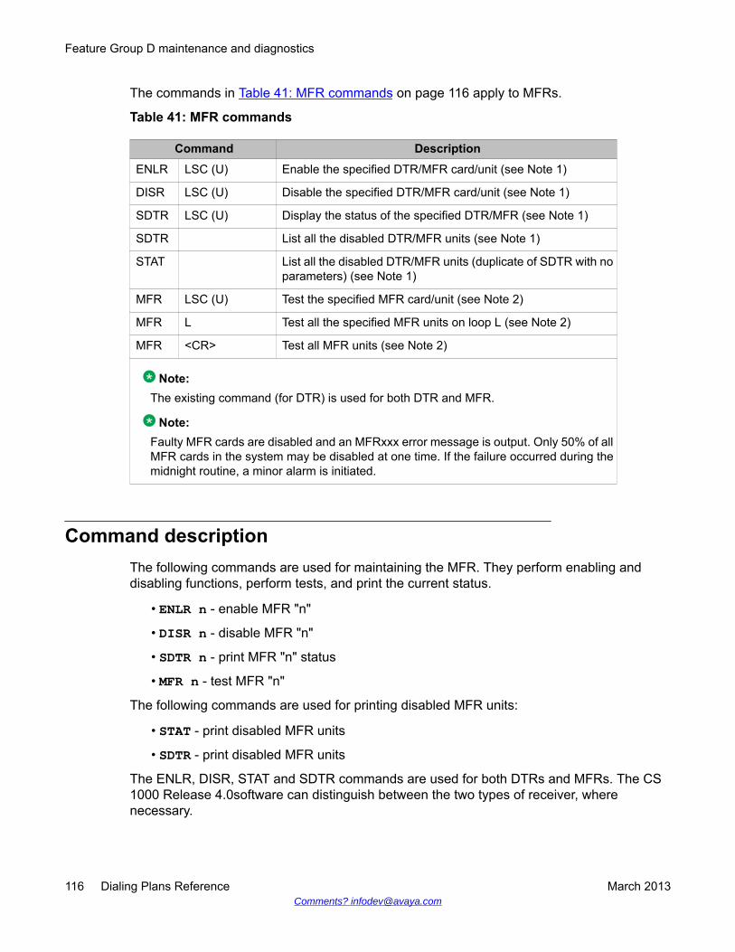
The commands in Table 41: MFR commands on page 116 apply to MFRs.
Table 41: MFR commands
Command DescriptionENLR LSC (U) Enable the specified DTR/MFR card/unit (see Note 1)
DISR LSC (U) Disable the specified DTR/MFR card/unit (see Note 1)
SDTR LSC (U) Display the status of the specified DTR/MFR (see Note 1)
SDTR List all the disabled DTR/MFR units (see Note 1)
STAT List all the disabled DTR/MFR units (duplicate of SDTR with noparameters) (see Note 1)
MFR LSC (U) Test the specified MFR card/unit (see Note 2)
MFR L Test all the specified MFR units on loop L (see Note 2)
MFR <CR> Test all MFR units (see Note 2)
Note:The existing command (for DTR) is used for both DTR and MFR.
Note:Faulty MFR cards are disabled and an MFRxxx error message is output. Only 50% of allMFR cards in the system may be disabled at one time. If the failure occurred during themidnight routine, a minor alarm is initiated.
Command descriptionThe following commands are used for maintaining the MFR. They perform enabling anddisabling functions, perform tests, and print the current status.
• ENLR n - enable MFR "n"
• DISR n - disable MFR "n"
• SDTR n - print MFR "n" status
• MFR n - test MFR "n"
The following commands are used for printing disabled MFR units:
• STAT - print disabled MFR units
• SDTR - print disabled MFR units
The ENLR, DISR, STAT and SDTR commands are used for both DTRs and MFRs. The CS1000 Release 4.0software can distinguish between the two types of receiver, wherenecessary.
Feature Group D maintenance and diagnostics
116 Dialing Plans Reference March 2013Comments? [email protected]
Disabling an MFR (DISR command) that is at present active in a call, disconnects the call. Noerror messages are given (as for TDET and DTR).
The MFR command performs the following tests:
• response test
• self-test (internal test of the card by its processor)
• valid reception test of all MF tones: An MFS is connected to the MFR through a networktimeslot. The MFS is triggered to send MF tones to the MFR, and the correct reception ischecked
If the MFR is busy, no test is performed (as for TDET and DTR), and the TDS315 message isprinted.
During midnight routines, the MFR command is performed.
The following are additional comments on the above section:
• For commands ENLR and DISR: "n" can only be LSC or LSCU
• For command STAT: no other parameters can be given
• For command SDTR: if "n" is specified, it can only be LSC or LSCU. If "n" is not specified,all disabled MFR units are printed
• For command MFR: "n" can be one of LSC, LSCU, L or <CR> (which causes a test to beperformed on all MFRs)
LD 30 : Network and signaling diagnostics• Signaling test of MFRs is supported by this overlay.
• Signaling test of FGDT trunks is supported. The test is performed for all trunks. Forexample, if all units of the FGDT trunk card are idle, an "existence" message is sent tothe card. It is then required to return the same message to the CPU.
Testing FGDT trunks and MFRs during midnight routines is supported.
LD 32 : Network peripheral equipment diagnosticsStandard enable, disable, and status commands are supported for MFRs. For FGDT trunks,all applicable trunk commands are supported.
Changes are made for this program to include the following responses where applicable (forexample, status of specific card).
LD 30 : Network and signaling diagnostics
Dialing Plans Reference March 2013 117

Normal responses include
• MFR (Multifrequency receiver)
Mnemonics for trunk types include
• FGDT (Feature Group D trunk)
Feature Group D maintenance and diagnostics
118 Dialing Plans Reference March 2013Comments? [email protected]

Chapter 11: Flexible Numbering Planadministration
Navigation• Introduction on page 119
• Electronic Switched Network (ESN) data on page 120
• Electronic Switched Network 2 (ESN2) data on page 121
• Electronic Switched Network (ESN) translation tables on page 124
• Customer data block configuration on page 127
• Customer data block configuration on page 127
• Flexible Numbering Plan configuration on page 129
IntroductionThere are six steps to configuring Flexible Numbering Plan:
Configuring Flexible Numbering Plan
1. Configure Network Control (NCTL) data block in LD 87 (ESN2) as required.2. Configure Route Data Blocks (RDB) and trunks as required.3. Configure Electronic Switched Network (ESN) data block through LD 86 (ESN1)
and ensure the following parameters are configured. Electronic Switched Network(ESN) data on page 120
4. Configure Coordinated Dialing Plan (CDP) and Free Special Number Screening(FSNS) as required in Electronic Switched Network (ESN) data block through LD87 (ESN2). Electronic Switched Network 2 (ESN2) data on page 121
5. Configure Network Translations as required in Electronic Switched Network 3(ESN3) Translation Tables data block through LD 90 (ESN3). Electronic SwitchedNetwork (ESN) translation tables on page 124
Dialing Plans Reference March 2013 119
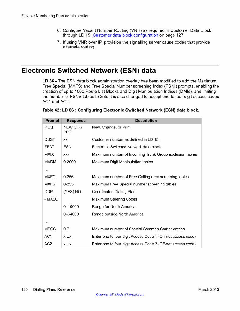
6. Configure Vacant Number Routing (VNR) as required in Customer Data Blockthrough LD 15. Customer data block configuration on page 127
7. If using VNR over IP, provision the signalling server cause codes that providealternate routing.
Electronic Switched Network (ESN) dataLD 86 - The ESN data block administration overlay has been modified to add the MaximumFree Special (MXFS) and Free Special Number screening Index (FSNI) prompts, enabling thecreation of up to 1000 Route List Blocks and Digit Manipulation Indices (DMIs), and limitingthe number of FSNS tables to 255. It is also changed to accept one to four digit access codesAC1 and AC2.
Table 42: LD 86 : Configuring Electronic Switched Network (ESN) data block.
Prompt Response DescriptionREQ NEW CHG
PRTNew, Change, or Print
CUST xx Customer number as defined in LD 15.
FEAT ESN Electronic Switched Network data block
MXIX xxx Maximum number of Incoming Trunk Group exclusion tables
MXDM 0-2000 Maximum Digit Manipulation tables
…
MXFC 0-256 Maximum number of Free Calling area screening tables
MXFS 0-255 Maximum Free Special number screening tables
CDP (YES) NO Coordinated Dialing Plan
- MXSC Maximum Steering Codes
0–10000 Range for North America
0–64000 Range outside North America
…
MSCC 0-7 Maximum number of Special Common Carrier entries
AC1 x…x Enter one to four digit Access Code 1 (On-net access code)
AC2 x…x Enter one to four digit Access Code 2 (Off-net access code)
Flexible Numbering Plan administration
120 Dialing Plans Reference March 2013Comments? [email protected]
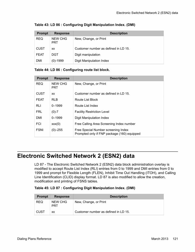
Table 43: LD 86 : Configuring Digit Manipulation Index. (DMI)
Prompt Response DescriptionREQ NEW CHG
PRTNew, Change, or Print
CUST xx Customer number as defined in LD 15.
FEAT DGT Digit manipulation
DMI (0)-1999 Digit Manipulation Index
Table 44: LD 86 : Configuring route list block.
Prompt Response DescriptionREQ NEW CHG
PRTNew, Change, or Print
CUST xx Customer number as defined in LD 15.
FEAT RLB Route List Block
RLI 0–1999 Route List Index
FRL (0)-7 Facility Restriction Level
DMI 0–1999 Digit Manipulation Index
FCI xxx(0) Free Calling Area Screening Index number
FSNI (0)–255 Free Special Number screening IndexPrompted only if FNP package (160) equipped
Electronic Switched Network 2 (ESN2) dataLD 87 - The Electronic Switched Network 2 (ESN2) data block administration overlay ismodified to accept Route List Index (RLI) entries from 0 to 1999 and DMI entries from 0 to1999 and prompt for Flexible Length (FLEN), Inhibit Time Out Handling (ITOH), and CallingLine Identification (CLID) display format. LD 87 is also modified to allow the creation,modification and printing of FSNS tables.
Table 45: LD 87 : Configuring Digit Manipulation Index. (DMI)
Prompt Response DescriptionREQ NEW CHG
PRTNew, Change, or Print
CUST xx Customer number as defined in LD 15.
Electronic Switched Network 2 (ESN2) data
Dialing Plans Reference March 2013 121
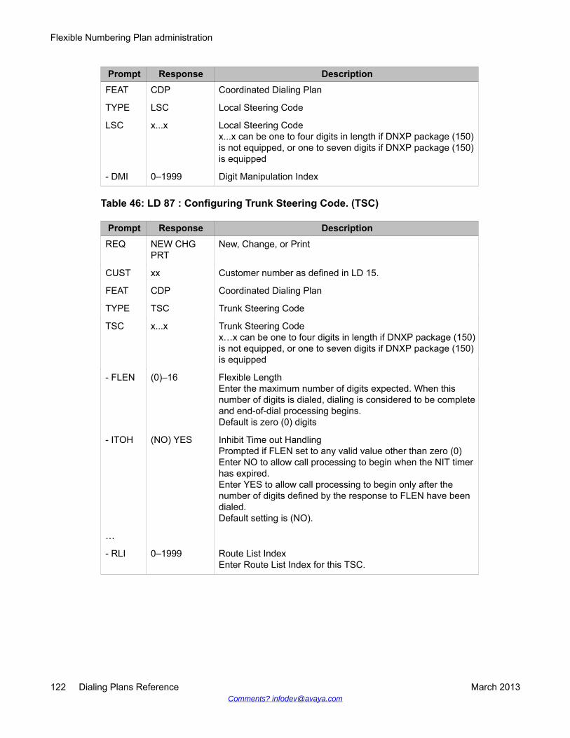
Prompt Response DescriptionFEAT CDP Coordinated Dialing Plan
TYPE LSC Local Steering Code
LSC x...x Local Steering Codex...x can be one to four digits in length if DNXP package (150)is not equipped, or one to seven digits if DNXP package (150)is equipped
- DMI 0–1999 Digit Manipulation Index
Table 46: LD 87 : Configuring Trunk Steering Code. (TSC)
Prompt Response DescriptionREQ NEW CHG
PRTNew, Change, or Print
CUST xx Customer number as defined in LD 15.
FEAT CDP Coordinated Dialing Plan
TYPE TSC Trunk Steering Code
TSC x...x Trunk Steering Codex…x can be one to four digits in length if DNXP package (150)is not equipped, or one to seven digits if DNXP package (150)is equipped
- FLEN (0)–16 Flexible LengthEnter the maximum number of digits expected. When thisnumber of digits is dialed, dialing is considered to be completeand end-of-dial processing begins.Default is zero (0) digits
- ITOH (NO) YES Inhibit Time out HandlingPrompted if FLEN set to any valid value other than zero (0)Enter NO to allow call processing to begin when the NIT timerhas expired.Enter YES to allow call processing to begin only after thenumber of digits defined by the response to FLEN have beendialed.Default setting is (NO).
…
- RLI 0–1999 Route List IndexEnter Route List Index for this TSC.
Flexible Numbering Plan administration
122 Dialing Plans Reference March 2013Comments? [email protected]
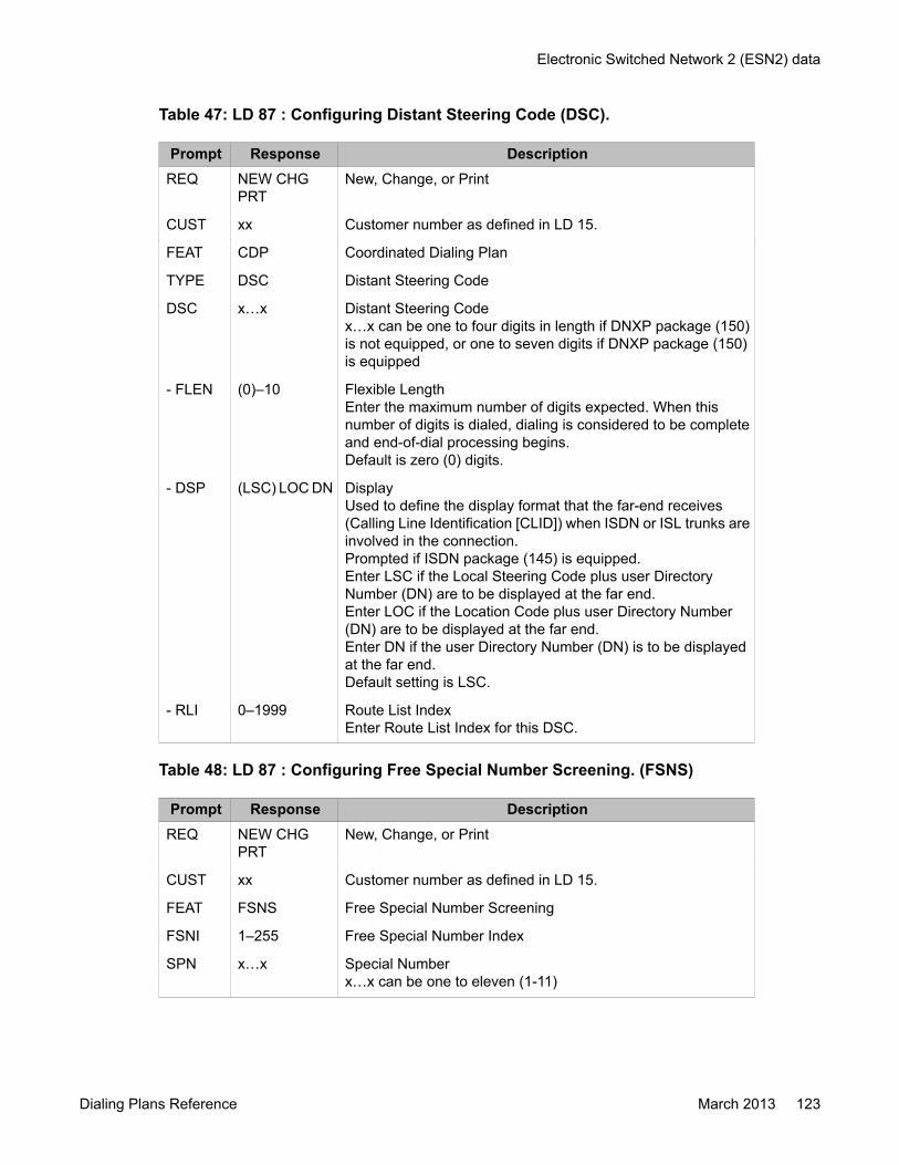
Table 47: LD 87 : Configuring Distant Steering Code (DSC).
Prompt Response DescriptionREQ NEW CHG
PRTNew, Change, or Print
CUST xx Customer number as defined in LD 15.
FEAT CDP Coordinated Dialing Plan
TYPE DSC Distant Steering Code
DSC x…x Distant Steering Codex…x can be one to four digits in length if DNXP package (150)is not equipped, or one to seven digits if DNXP package (150)is equipped
- FLEN (0)–10 Flexible LengthEnter the maximum number of digits expected. When thisnumber of digits is dialed, dialing is considered to be completeand end-of-dial processing begins.Default is zero (0) digits.
- DSP (LSC) LOC DN DisplayUsed to define the display format that the far-end receives(Calling Line Identification [CLID]) when ISDN or ISL trunks areinvolved in the connection.Prompted if ISDN package (145) is equipped.Enter LSC if the Local Steering Code plus user DirectoryNumber (DN) are to be displayed at the far end.Enter LOC if the Location Code plus user Directory Number(DN) are to be displayed at the far end.Enter DN if the user Directory Number (DN) is to be displayedat the far end.Default setting is LSC.
- RLI 0–1999 Route List IndexEnter Route List Index for this DSC.
Table 48: LD 87 : Configuring Free Special Number Screening. (FSNS)
Prompt Response DescriptionREQ NEW CHG
PRTNew, Change, or Print
CUST xx Customer number as defined in LD 15.
FEAT FSNS Free Special Number Screening
FSNI 1–255 Free Special Number Index
SPN x…x Special Numberx…x can be one to eleven (1-11)
Electronic Switched Network 2 (ESN2) data
Dialing Plans Reference March 2013 123

Prompt Response DescriptionSPN is re-prompted until only a <CR> (Carriage Return) isentered.
XXX ALOW DENY XXX codes to be allowed or denied.Enter ALOW to configure Special Number codes that are to beallowed.Enter DENY to configure Special Number codes that are to bedenied.
- ALOW xxx Allow codesPrompted if response to XXX was ALOWxxx can be entered as a three (3) digit code, (that is, 123, wherethe number 123 is allowed) or as a range of three (3) digit codes,(that is, 100 199, where all numbers in the range 100 to 199 areallowed)
- DENY xxx Deny codesPrompted if response to XXX was DENYxxx can be entered as a three (3) digit code, (that is, 123, wherethe number 123 is denied) or as a range of three (3) digit codes,(that is, 100 199, where all numbers in the range 100 to 199 aredenied)
Electronic Switched Network (ESN) translation tablesLD 90 - Electronic Switched Network 3 (ESN3) Translation Tables is modified to accept RLIentries from 0 to 1999 and DMI entries from 1 to 1999 and prompt for FLEN, ITOH, ARRN,and ARLI.
Table 49: LD 90 : Configuring network translator.
Prompt Response DescriptionREQ NEW CHG
PRTNew, Change, or Print
CUST xx Customer number as defined in LD 15.
FEAT NET Network Translator
TRAN AC1 AC2 Translator
TYPE LOC Location Code
LOC x...x Location code
- FLEN (0)–24 Flexible LengthEnter the maximum number of digits expected. When thisnumber of digits is dialed, dialing is considered to be completeand end-of-dial processing begins.
Flexible Numbering Plan administration
124 Dialing Plans Reference March 2013Comments? [email protected]

Prompt Response DescriptionDefault is zero (0) digits
- RLI 0–1999 Route List IndexEnter Route List Index for this LOC.
Table 50: LD 90 : Configuring network translator.
Prompt Response DescriptionREQ NEW CHG
PRTNew, Change, or Print
CUST xx Customer number as defined in LD 15.
FEAT NET Network Translator
TRAN AC1 AC2 Translator
TYPE HLOC Home Location Code
HLOC x...x Home Location code (3 digits) or extended code (3-7 digits)
DMI 1–1999 Digit Manipulation Index
Table 51: LD 90 : Configuring network translator.
Prompt Response DescriptionREQ NEW CHG
PRTNew, Change, or Print
CUST xx Customer number as defined in LD 15.
FEAT NET Network Translator
TRAN AC1 AC2 Translator
TYPE NPA Numbering Plan Area code
NPA
xxx xxx yyy1xxx 1xxx yyy
Numbering Plan Area code translation, extended NPA codetranslation (a leading zero is not allowed).Area code translation Extended NPA code translation 3-10digits or 4-11 digits with 1+ dialing. Enter the NPA code (xxx)and the extended code (yyy) separated by a space.Area code translation (1+ dialing) Extended NPA codetranslation (1+ dialing) Where: xxx & yyy = 200 - 999
…
- RLI 0–1999 Route List IndexEnter Route List Index for this NPA
- SDRR LDID Recognized Local Direct Inward Dial codes
- DMI 1–1999 Digit Manipulation Index
Electronic Switched Network (ESN) translation tables
Dialing Plans Reference March 2013 125

Table 52: LD 90 : Configuring numbering plan exchange.
Prompt Response DescriptionREQ NEW CHG
PRTNew, Change, or Print
CUST xx Customer number as defined in LD 15.
FEAT NET Network Translator
TRAN AC1 AC2 Translator
TYPE NXX Numbering plan exchange code
NXX
xxx 1xxx xxxyyy<CR>
Numbering Plan Exchange (Central Office) (A leading zero isnot allowed)Office code translation Office code translation (1+ dialing)Extended NXX code translation3-7 digits or 4-8 digits with 1+ dialing. Enter the NXX code (xxx)and the extended code (yyy) separated by a space.Return to REQ
…
- RLI 0–1999 Route List IndexEnter Route List Index for this NXX.
- SDRR LDID Recognized Local Direct Inward Dial codes
- DMI 1–1999 Digit Manipulation Index
Table 53: LD 90 : Configuring Special Number (SPN).
Prompt Response DescriptionREQ NEW CHG
PRTNew, Change, or Print
CUST xx Customer number as defined in LD 15.
FEAT NET Network Translator
TRAN AC1 AC2 Translator
TYPE SPN TYPE of translation: Special Number
SPN x…x Special NumberEnter Special Number. Number can be from 1 to 11 digits
- FLEN (0)–16 Flexible LengthEnter the maximum number of digits expected. When thisnumber of digits is dialed, dialing is considered to be completeand end-of-dial processing begins.Default is zero (0) digits
- ITOH (NO) YES Inhibit Time out HandlingPrompted if FLEN set to any valid value other than zero (0).
Flexible Numbering Plan administration
126 Dialing Plans Reference March 2013Comments? [email protected]
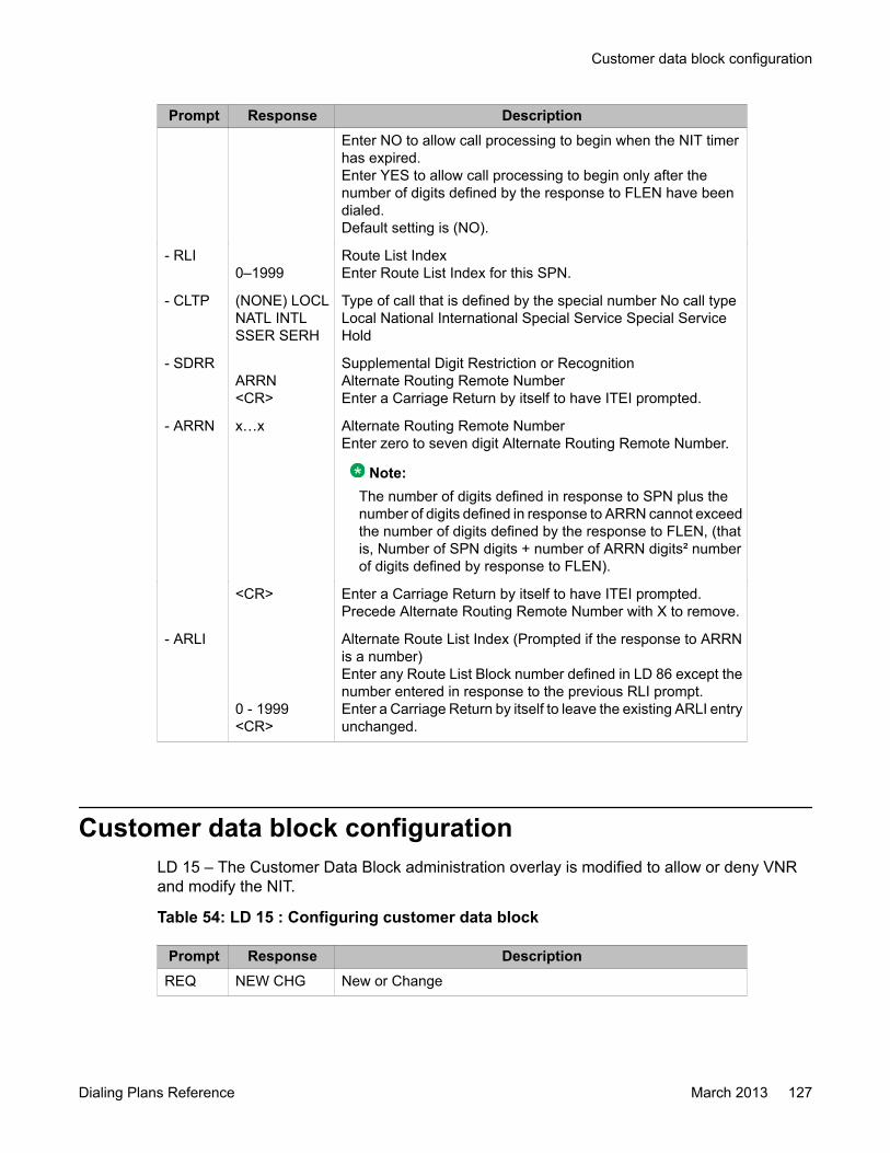
Prompt Response DescriptionEnter NO to allow call processing to begin when the NIT timerhas expired.Enter YES to allow call processing to begin only after thenumber of digits defined by the response to FLEN have beendialed.Default setting is (NO).
- RLI0–1999
Route List IndexEnter Route List Index for this SPN.
- CLTP (NONE) LOCLNATL INTLSSER SERH
Type of call that is defined by the special number No call typeLocal National International Special Service Special ServiceHold
- SDRRARRN<CR>
Supplemental Digit Restriction or RecognitionAlternate Routing Remote NumberEnter a Carriage Return by itself to have ITEI prompted.
- ARRN x…x Alternate Routing Remote NumberEnter zero to seven digit Alternate Routing Remote Number.
Note:The number of digits defined in response to SPN plus thenumber of digits defined in response to ARRN cannot exceedthe number of digits defined by the response to FLEN, (thatis, Number of SPN digits + number of ARRN digits² numberof digits defined by response to FLEN).
<CR> Enter a Carriage Return by itself to have ITEI prompted.Precede Alternate Routing Remote Number with X to remove.
- ARLI
0 - 1999<CR>
Alternate Route List Index (Prompted if the response to ARRNis a number)Enter any Route List Block number defined in LD 86 except thenumber entered in response to the previous RLI prompt.Enter a Carriage Return by itself to leave the existing ARLI entryunchanged.
Customer data block configurationLD 15 – The Customer Data Block administration overlay is modified to allow or deny VNRand modify the NIT.
Table 54: LD 15 : Configuring customer data block
Prompt Response DescriptionREQ NEW CHG New or Change
Customer data block configuration
Dialing Plans Reference March 2013 127

Prompt Response DescriptionTYPE NET Networking
CUST 0-99 Customer Number as defined in LD 15.
OPT a…a Options
AC2 Access Code 2
NPA E.164 National
NXX E.164 Subscriber
INTL International
SPN Special Number
LOC Location Code
VNR (NO) YES Vacant Number RoutingPrompted only if FNP package (160) is equipped.Enter NO if vacant numbers are not to be routed to another nodefor treatment.Enter YES if vacant numbers are to be routed to another nodefor treatment.For nodes connected by trunks that use in-band signaling (DTI,DTI2, or analog trunks): The VNR setting in the terminatingnode's Customer Data Block determines whether or not to useVacant Number Routing.For nodes connected by trunks that use out-of-band signaling(ISDN or ISL trunks): The VNR setting in the originating node'sCustomer Data Block determines whether or not to use VacantNumber Routing.Default is (NO).
- RLI 0-1999 Route List IndexEnter route list, defined in LD 86, to be used by Vacant NumberRouting.
- FLEN 1-(16) Flexible length of digits expected
- CDPL 1-(10) Coordinated Dialing Plan LengthEnter the maximum number of Coordinated Dialing Plan (CDP)digits expected by Vacant Number Routing.Default is (10) digits.
- LOCL 1-(10) Location Code LengthEnter the maximum number of Location (LOC) digits expectedby Vacant Number Routing.Default is (10) digits.
NIT 2-(8) NARS (Network Alternate Route Selection) Interdigit TimerPrompted if NARS package (58) is equipped.Enter the number of seconds allowed between CDP or LOCdigits before end-of-dial processing is invoked.Default is eight (8) seconds.
Flexible Numbering Plan administration
128 Dialing Plans Reference March 2013Comments? [email protected]
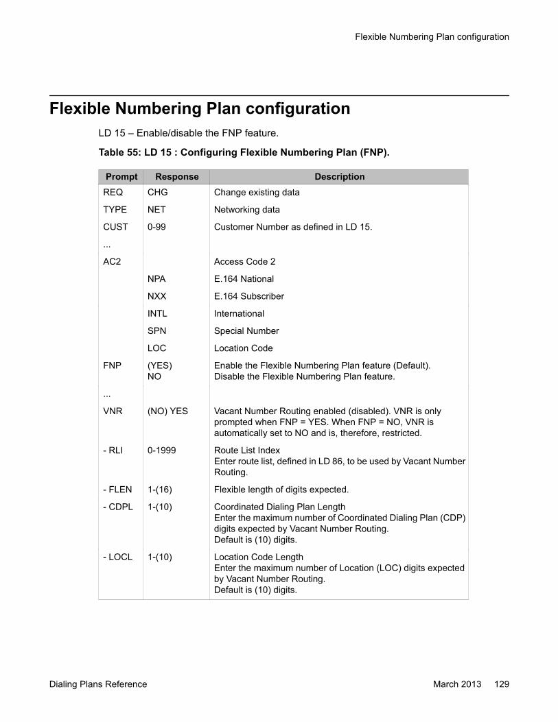
Flexible Numbering Plan configurationLD 15 – Enable/disable the FNP feature.
Table 55: LD 15 : Configuring Flexible Numbering Plan (FNP).
Prompt Response DescriptionREQ CHG Change existing data
TYPE NET Networking data
CUST 0-99 Customer Number as defined in LD 15.
...
AC2 Access Code 2
NPA E.164 National
NXX E.164 Subscriber
INTL International
SPN Special Number
LOC Location Code
FNP (YES)NO
Enable the Flexible Numbering Plan feature (Default).Disable the Flexible Numbering Plan feature.
...
VNR (NO) YES Vacant Number Routing enabled (disabled). VNR is onlyprompted when FNP = YES. When FNP = NO, VNR isautomatically set to NO and is, therefore, restricted.
- RLI 0-1999 Route List IndexEnter route list, defined in LD 86, to be used by Vacant NumberRouting.
- FLEN 1-(16) Flexible length of digits expected.
- CDPL 1-(10) Coordinated Dialing Plan LengthEnter the maximum number of Coordinated Dialing Plan (CDP)digits expected by Vacant Number Routing.Default is (10) digits.
- LOCL 1-(10) Location Code LengthEnter the maximum number of Location (LOC) digits expectedby Vacant Number Routing.Default is (10) digits.
Flexible Numbering Plan configuration
Dialing Plans Reference March 2013 129

Flexible Numbering Plan administration
130 Dialing Plans Reference March 2013Comments? [email protected]
Chapter 12: Zone Based Dialing planconfiguration
Navigation• Introduction on page 131• Element Manager on page 137• Phones configuration in Element Manager on page 146• E.164 dial plan configuration on page 155• Local Dialing on page 187• Private dialing on page 189• Call Flow for Local Dialing on page 195• Call Flow for emergency dialing with SBO on page 198• Call Flow for emergency dialing with SMG on page 200• Initial DN key download for Local DN (3-5 digits) on page 202• LD Tables on page 206• Diagnostic logs on page 209
IntroductionThe Zone Based Dialing (ZBD) feature enables the consolidation of small, traditional PBXsystems in multiple enterprise locations into a single or a small number of high-capacity callservers and branch gateways for PSTN access. New customers who plan to setup a privatenetwork in multiple locations can also deploy ZBD. The migration to a single high-capacity CallServer is transparent to the end user. For example, the private and public (E.164) dialing plansand features are retained. Numbering zones are introduced to differentiate the dialing andnumbering patterns for every location. All dialing and numbering parameters are configuredfor each numbering zone. Each telephone must be configured with a numbering zone.
The Zone Based Dialing (ZBD) feature supports both public and private dial and numberingplans for on-net calls. For outgoing trunk calls, if a DIALPLAN is configured, the Calling Line
Dialing Plans Reference March 2013 131
Identification (CLID) is converted to E.164 format as PUB. CLID remains unchanged for PRVtype dial plans.
The ZBD model for dial plan management has the following characteristics.
• User DN is seven-digits in length where the leading digits identify the home location.• Users are assigned numbering zones.• Users in the same numbering zone can dial extensions with a system specified length—
typically four-digits (similar to CDP- style dialing.)• Users across various numbering zones dial access codes and location codes or E.164
numbers, which are translated from site-specific dialing patterns to system-specificdigits.
Numbering zones are configured for each phone in LD 10 and LD 11. For outgoing VTRK calls,Country Code, NPA, and NXX are sent within ZBD IE of the Integrated Services Digital Network(ISDN) message. The terminating party processes this IE accordingly. The DIALPLAN promptis added to LD 15. If DIALPHONE is configured to PUB, the appropriate E.164 CLID appearson a terminating telephone. Numbering zones assigned to an attendant console in LD 12 arealso configurable.
The Zone Based Flexible Dialing Plan (ZFDP) simplifies the dial plan configuration. Numberingzones contain zone-specific information such as site prefix, country code, and access prefixes(for international, national, and subscriber calls). For every call, information is retrieved fromthe numbering zone to process the CLID. ZFDP reduces the complexity of configuration. Everytime an access code for an intersite call is dialed, the dialed digits are checked in the ZFDPtable, if a match is found, the system AC1/AC2, country code, and area code are added,depending on the ZFDP entry type. ZFDP is configured on the SPN and normalizes a publicdialed number into an E.164 number for routing. You must configure the seven-digit DN. TheDN is composed of two parts: the zone and site prefix (2 to 4 digits) and the extension (3 to 5digits). Typically, three-digits are assigned for the zone and site prefix and four-digits for theextension. For dialing in the same zone and site, the zone and site prefix is not dialed ordisplayed. For intersite calls where the public dial plan for on-net calls has been configured,the zone and site prefix are replaced by the corresponding E.164 number. You do not need toconfigure TSC blocks to remove the site prefix prior to routing intersite calls.
The ZBD on-net call routing (intersite) requires users to dial an E.164 number (eitherinternational or national number) for calls between sites, when the DIALPLAN is configuredPUB. For more information about on-net dialing, see On-net dialing with abbreviated E.164numbers on page 173.
The migration from traditional PBX systems in multiple enterprise locations to a single highcapacity call server model is transparent to the end users. For more information, see Migrationplanning on page 134.
The private and public (E.164) dial plans and features are retained. Using the digit manipulationtables, the P character can be inserted as the numbering zone prefix in the dialed digits string.The C character can also be inserted to represent the country code of the terminating TN.Using the P and C characters in the digit manipulation tables, reduces the number of DMIentries required and the complexity of configurations if the Survivable Media Gateways arelocated in different countries. For an example, see Figure 36: Call flow for Private dialing duringWAN outage on page 205.
Avaya recommends using a dial pattern to send the digits as E.164 international numbers withthe destination country code that is uniquely identified by the originating zone prefix. The
Zone Based Dialing plan configuration
132 Dialing Plans Reference March 2013Comments? [email protected]
Network Routing Server (NRS), identifies the originating SMG and can be configured to choosethe best route for PSTN access.
Important:If using the ZBD feature, you must enable and configure it for each call server.
High level tasks for configuring ZBDThe following list provides the high level tasks necessary to configure ZBD. Upon completionof configuring and assigning the PREF of the IP phones to a zone, all first dialed digits areprefixed with PREF. Each zone can be assigned to a numbering plan with the site prefix. Ensureeach zone is separated to avoid dialing conflicts.
• LD 22: Install required package. See Required packages on page 133.
• LD 15: Enable the ZBD option and configure DIALPLAN to the appropriate dial plan (PUB/PRV).
• Configure numbering zones for your telephones using Element Manager (EM)
• Configure numbering zone parameters (PREF, CC, NPA, ACx, INTC, NATC) using EM.
• Configure CLID entries for a phone key.
• Configure phones with numbering zones and appropriate CLIDs. The DN of a telephoneshould be seven-digits: PREF + shortDN.
• Configure ZFDP for numbering zones (optional).
• Configure ESN blocks for routing (SPN, TSC).
Required packagesThe service package 420 (ZBD) is required. This package is added to the Enhanced Servicepackage (Tier 1) to all systems and added to the key code of all systems.
LimitationsYou must configure the first 2 to 4 digits of the seven-digit DN as the numbering zone prefix.
Avaya Communication Server 1000 continues to support seven-digit DNs, that do not supporta unique extension based on E.164 formatting, that is, seven-digits only supports NXX-XXXXwhich are not always unique. Avaya does not recommend NXX as a zone prefix because itconflicts with the system access code. Choose access code AC1/AC2 so that it does notconflict with the zone prefix. Do not configure a zone prefix as it conflicts with dial prefixes(NXX, NPA, INTL) in the ZFDP table. For example, if NPA dial prefix is equal to <AC> 1, thenPREF 1xx is not allowed.
Introduction
Dialing Plans Reference March 2013 133

DN Call Pickup requires a seven-digit DN of the ringing telephone entered after the DN Pickupkey is pressed. The base software does not apply pre-translation to the number entered afterthe DN Pickup key is pressed. (Normal and Group Pickup work fine.)
You must dial the same number, for example, *26 yyy xxxx) to retrieve a parked call from thesame or a different Call Server, where *26 is the FFC and yyy xxxx is the System Park DN.The two methods of using the Call Park feature are as follows:
Using a System Extension:
• To park a call: press the Park key twice and remember the displayed system extension.
• To retrieve a parked call: dial *xxx where *xxx is configured as FFC (for example, *247,or *24, or *2, or *) followed by the system extension.
Using the DN of a telephone:
• To park a call: the seven-digit DN of the telephone must be entered.
• To retrieve a parked call: dial *xxx followed by the seven-digit DN.
Hunt and FDN for E.164 numbers is not supported. The administrator must enter the seven-digit DN because the base software does not apply pre-translation to Hunt and FDNconfigurations.
The administrator must enter the CFW DN from LD 10 and 11 with the Numzone prefix in thebeginning of CFW DN. Consider also, the CFW length of a key, including the length of theNumzone prefix, while configuring a set.
Most Avaya CallPilot features do not work with mail box numbers defined as E.164 numbersor short DNs. A sample list of features not supported includes the following examples:
• You must enter the full seven-digit mail box number in response to the request fromCallPilot to access the CallPilot (or the you can use the # key at a desktop telephone).The CallPilot cannot uniquely identify all the users with a four-digit number.
• Use the seven-digit DN in the voice greetings. It is recommended that you use namegreeting.
• Do not use the Revert DN, it is not supported (unless you use a seven-digit DN).
• Do not use distribution lists, they are not supported (unless you use a seven-digit DN)
Zone Alternative Routing feature does not work with OC in Computer mode, which is a BASElimitation.
Migration planningThe main advantages for deploying or migrating to Zone Based Dialing (ZBD) are:
• system consolidation• centralized maintenance and monitoring
Zone Based Dialing plan configuration
134 Dialing Plans Reference March 2013Comments? [email protected]
• easier introduction of new features and upgrades• overall reduction in capital and operating expenditure• smooth migration to next generation IP network• fully integrated applications (Voice Mail, System management, Attendant console)• interworking with Microsoft OCS application• compatibility with existing user dial plan for on-net E.164 and off-net access (with
Centralized Routing using the NRS where possible)
Deployment optionsConsider the following deployment options for ZBD:
• Communication Server 1000E and a Survivable Media Gateway (SMG)
• Main Office and Branch Office model
• Multiple Call Servers for large deployments
Private Numbering Plan (CDP/UDP)Numbering zones are used as a method of representing a single location. All dialing andnumbering parameters are configured on a numbering zone basis. Each telephone must beconfigured with a numbering zone.
When collapsing multiple enterprise locations into a single call server, DNs are converted toseven-digit DNs to avoid a number conflict.
In the following example:
BVW location has the on-net number (LOC: 343)-2000 and the BNG location is (877)-2000.The 2000 DN is the same at both locations. When using ZBD, to avoid a conflict, you mustconvert to a seven-digit DN. After converting to a seven-digit DN, the BVW location DN is3432000 and the BNG location DN is 8772000.
After the numbering zone is created, a user at the BVW location (343) dials only the uniquetrailing digits within that numbering zone. This is known as the abbreviated local or private dialplan. The first 2 to 4 digits of the seven-digit DN are configured as the numbering zone prefixand the remaining digits are the extension that is dialed within the same site or numberingzone. For ZBD to work, a seven-digit DN must be configured. For local dialing within the samenumbering zone, the 343 digits are configured as a Zone Prefix against that numberingzone.
Introduction
Dialing Plans Reference March 2013 135

Public E.164 numbering and Dial PlanThe E.164 dial plan is configured using the DIALPLAN prompt in overlay 15 as PUB for publicdial plan. With this configuration, all the intersite calls are dialed and the CLID is displayed inE.164 format.
Several sites can belong to the same call server. Calls between these sites are routed asinternal calls even though the E.164 number is dialed. This is because the phones at thesesites are registered or configured on the same call server. Therefore, the dialed E.164 numberis converted to the internal seven-digit DN for local termination. NRS is not involved for thistype of call. With a larger deployment, more than one call server is required. In a scenariowhere you make a call to a site on a different call server, the call between these sites is a virtualtrunk call. The dial plan must be configured for both on-net and PSTN calls as these numbersare dialed in the E.164 format. The E.164 dial plan is configured using the DIALPLAN promptin overlay 15 as PUB for public dial plan. With this configuration, all the intersite calls are dialedand the CLID is displayed in E.164 format.
With a larger deployment, more than one call server is required. In a scenario where you makea call to a site on a different call server, the call between these sites is a virtual trunk call. Thedial plan must be configured for both on-net and PSTN calls as these numbers are dialed inthe E.164 format.
For more information about configuring E.164, see E.164 dial plan configuration onpage 155.
Dial Plan considerationsPlanning of your dial plan is critical for a successful Zone Based Dialing (ZBD) deployment.You can control call routing across multiple sites with various dial plans using a centralized dialplan. Consider the following when planning your dial plan for migration to ZBD:
• independent dialing patterns for each location
• local dialing – dial local extensions with 3 to 5 digits
• E.164 dialing:
- on-net E.164 numbers that terminate within a single Call Server
- on-net E.164 numbers that terminate between Call Servers
- on-net E.164 numbers that overflow to the PSTN network
- off-net/public E.164 numbers
- dialing of E.164 numbers that include:
• international dial prefixes
Zone Based Dialing plan configuration
136 Dialing Plans Reference March 2013Comments? [email protected]

• national dial prefixes
• local subscriber prefixes
• non-DID/DID Phones — for example, conference rooms and lobby
• special Numbers — for example, Emergency (ESA), Voice Mail, Help
• numbering plan to accommodate a large number of locations
Element ManagerUse the following procedures to configure Zone Based Dialing (ZBD). Element Managerdepends on LD 117 and LD 15 for the ZBD feature.
Numbering Zone configuration in Element ManagerIn the IP Network, Zones branch of the EM navigation tree, the following tasks can beperformed to configure NUMZONE for the ZBD feature.
• Enabling Numbering Zone on page 137• Adding a new Numbering Zone on page 138• Looking up the Country Code on page 141• Editing the Numbering Zones Data on page 142• Adding a New Dialing configuration on page 143• Configuring the Flexible Dial Plan on page 144• Configuring the Direct Inward Dial number on page 145
Enabling Numbering ZoneThe numbering zone must be enabled before you can configure numbering zones for a publicor private dial plan.
1. On the Element Manager navigation pane, select Customers.
2. Click the customer number for the numbering zone you want to enable.
The Customer Details page appears.
3. Click Features.
The Features page appears, as shown in the following figure.
Element Manager
Dialing Plans Reference March 2013 137

Figure 10: Features page
4. Select the check box Enable numbering zone.
5. Select the Dial Plan option Public or Private.
6. Click Save.
Adding a new Numbering Zone
Note:For High Scalability (HS) systems, after you use the Avaya CS 1000 Element Manager HighScalability (EM HS) interface to add new Numbering Zones on the reference High Availability(HA) group, the system propagates the new Numbering Zones to all of the HA groups.
Zone Based Dialing plan configuration
138 Dialing Plans Reference March 2013Comments? [email protected]
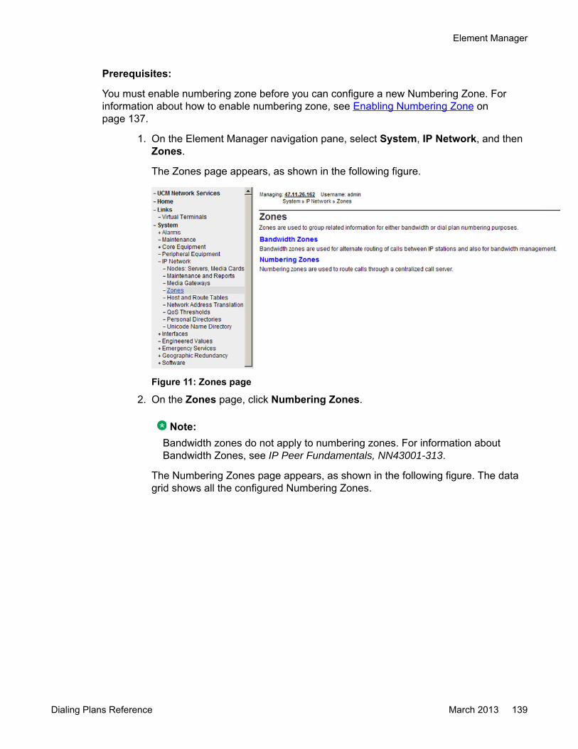
Prerequisites:
You must enable numbering zone before you can configure a new Numbering Zone. Forinformation about how to enable numbering zone, see Enabling Numbering Zone onpage 137.
1. On the Element Manager navigation pane, select System, IP Network, and thenZones.
The Zones page appears, as shown in the following figure.
Figure 11: Zones page
2. On the Zones page, click Numbering Zones.
Note:Bandwidth zones do not apply to numbering zones. For information aboutBandwidth Zones, see IP Peer Fundamentals, NN43001-313.
The Numbering Zones page appears, as shown in the following figure. The datagrid shows all the configured Numbering Zones.
Element Manager
Dialing Plans Reference March 2013 139
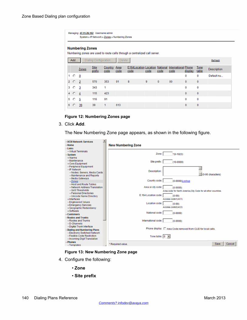
Figure 12: Numbering Zones page
3. Click Add.
The New Numbering Zone page appears, as shown in the following figure.
Figure 13: New Numbering Zone page
4. Configure the following:
• Zone
• Site prefix
Zone Based Dialing plan configuration
140 Dialing Plans Reference March 2013Comments? [email protected]

• Description
• Country code
- Click Lookup to look up the country code. For more information aboutLooking up the country code, see Looking up the Country Code onpage 141.
• Area code
• E.164 Location code
• Location code
• National code
• International code
• Phone display
• Tone table
5. Click Save.
Looking up the Country CodePerform the following procedure to look up the country code for a Numbering Zone.
1. On the Element Manager navigation pane, select System, IP Network, and thenZones.
The Zones page appears, as shown in Figure 11: Zones page on page 139.
2. On the Zones page, click Numbering Zones.
The Numbering Zones page appears, as shown in Figure 12: Numbering Zonespage on page 140. The data grid shows all the configured Numbering Zones.
3. Click a zone number under the Zones column.
The Numbering Zones Details (Zone #) page appears, as shown in Figure 15:Numbering Zones Details page on page 143.
4. In the Country Code section, click Lookup.
A new window opens allowing you to specify a country, as shown in the followingfigure.
Element Manager
Dialing Plans Reference March 2013 141

Figure 14: Country Code Lookup dialog box
5. Specify a Country option.
6. Click Assign.
Editing the Numbering Zones Data
Note:For High Scalability (HS) systems, after you use the Avaya CS 1000 Element Manager HighScalability (EM HS) interface to edit any of the values for Numbering Zones on the referenceHigh Availability (HA) group, the system updates the new values on all of the HA groups.
1. On the Element Manager navigation pane, select System > IP Network >Zones.
The Zones page appears, as shown in Figure 11: Zones page on page 139.
2. Click Numbering Zones.
The Numbering Zones page appears, as shown in Figure 12: Numbering Zonespage on page 140. The data grid shows all the configured Numbering Zones.
3. Choose an existing Zone by clicking the zone number.
The Numbering Zones Details (zone #) page appears, as shown in the followingfigure.
Zone Based Dialing plan configuration
142 Dialing Plans Reference March 2013Comments? [email protected]
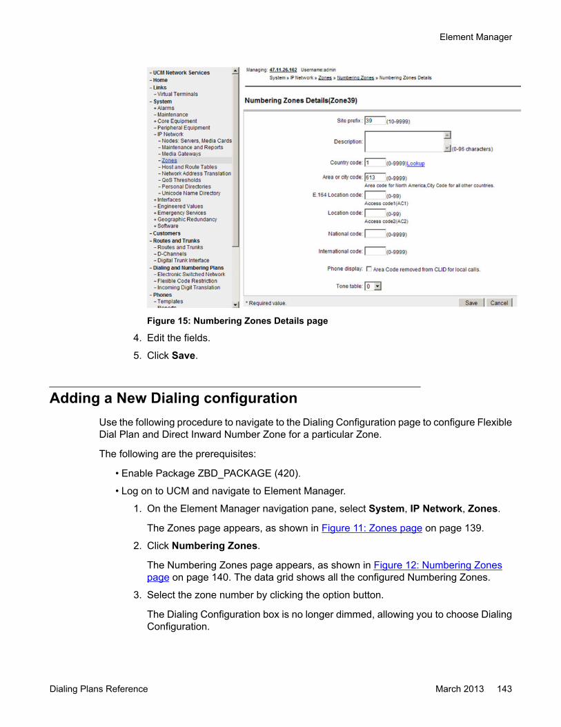
Figure 15: Numbering Zones Details page
4. Edit the fields.
5. Click Save.
Adding a New Dialing configurationUse the following procedure to navigate to the Dialing Configuration page to configure FlexibleDial Plan and Direct Inward Number Zone for a particular Zone.
The following are the prerequisites:
• Enable Package ZBD_PACKAGE (420).
• Log on to UCM and navigate to Element Manager.
1. On the Element Manager navigation pane, select System, IP Network, Zones.
The Zones page appears, as shown in Figure 11: Zones page on page 139.
2. Click Numbering Zones.
The Numbering Zones page appears, as shown in Figure 12: Numbering Zonespage on page 140. The data grid shows all the configured Numbering Zones.
3. Select the zone number by clicking the option button.
The Dialing Configuration box is no longer dimmed, allowing you to choose DialingConfiguration.
Element Manager
Dialing Plans Reference March 2013 143
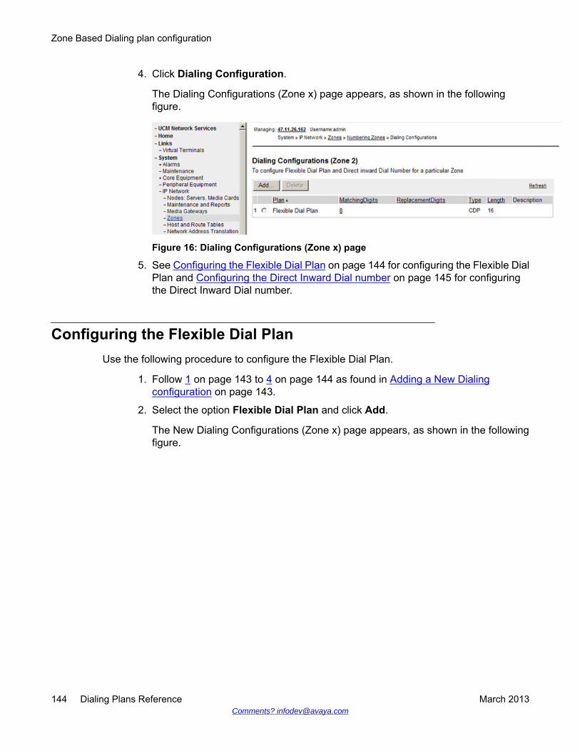
4. Click Dialing Configuration.
The Dialing Configurations (Zone x) page appears, as shown in the followingfigure.
Figure 16: Dialing Configurations (Zone x) page
5. See Configuring the Flexible Dial Plan on page 144 for configuring the Flexible DialPlan and Configuring the Direct Inward Dial number on page 145 for configuringthe Direct Inward Dial number.
Configuring the Flexible Dial PlanUse the following procedure to configure the Flexible Dial Plan.
1. Follow 1 on page 143 to 4 on page 144 as found in Adding a New Dialingconfiguration on page 143.
2. Select the option Flexible Dial Plan and click Add.
The New Dialing Configurations (Zone x) page appears, as shown in the followingfigure.
Zone Based Dialing plan configuration
144 Dialing Plans Reference March 2013Comments? [email protected]

Figure 17: New Dialing Configuration page
3. Configure the following fields to create a new Dialing Zone.
• Matching digits: (1-16 digits). Type a best match string and ensure it is uniquewithin a zone.
If the entered string matches a dialed number (for example, when DNTRANSfails), the matching string is removed and appropriate digits are inserted (fromreplacement string and ACx, if needed).
• Plan: Click Flexible Dial Plan.
• Select a Type and Length.
• Replacement digits: (1-16 digits).
• Description: (0-32 characters).
4. Click Save.
Configuring the Direct Inward Dial numberUse the following procedure to configure the Direct Inward Dial number
1. Follow 1 on page 143 to 4 on page 144 as found in Adding a New Dialingconfiguration on page 143.
2. Select the option Flexible Dial Plan and click Add.
The New Dialing Configurations (Zone x) page appears, as shown in Figure 17:New Dialing Configuration page on page 145.
Element Manager
Dialing Plans Reference March 2013 145

3. Configure the following fields to create a new Dialing Zone.
• Matching digits: (1-16 digits). Type a best match string and ensure it is uniquewithin a zone.
If the entered string matches a dialed number (for example, when DNTRANSfails), the matching string is removed and appropriate digits are inserted (fromreplacement string and ACx, if needed).
• Plan: Click Direct Inward Dial Number.
The Type and Length fields are dimmed.
• Replacement digits: (1-16 digits).
• Description: (0-32 characters).
4. Click Save.
Phones configuration in Element ManagerThe Numbering Zone configuration supports Analog, TDM, and IP Phones. This feature issupported in Communication Server 1000 Release 6.0 and later. You must enable Package420. The ZBD is enabled in the FTR_DATA for the customer in LD 15.
The Numbering Zone value is configured from 0 and 1023. A Numbering Zone value of 0signifies that no zone is used for the current unit.
The following are the dependencies:
• LD 10• LD 11• LD 20, 21, 22• LD 95
In the Phones branch of the Element Manager navigation tree, you can select the followingitems to configure phones with the Numbering Zone:
• Retrieving phones• Adding phones (Analog, IP ,TDM)• Editing Single/Bulk phones• Generating reports in HTML and CSV format• Moving a phone to a new TN• Swapping phones• Importing phones• Adding phones using a Template
Zone Based Dialing plan configuration
146 Dialing Plans Reference March 2013Comments? [email protected]
Retrieving a phone with NUMZONE configurationPerform the following procedure to retrieve phones.
The following prerequisites must be met:
• Log on to UCM.
1. In UCM, select a configured call server.
2. Ensure the necessary configuration of a customer is already available for a phoneto be configured (super loop or customer).
3. On the Element Manager navigation pane, select Phones.
Important:The phone database and call server database must be synchronized at alltimes.
4. On the Search for Phones page, click Retrieve.
The Retrieve options page appears.
Click Custom.
5. Specify a TN with NUMZONE configured on the Communication Server 1000.
The phone is retrieved from Communication Server 1000 and updated in the phonedatabase.
Adding a Phone with NUMZONE configurationPerform the following procedure to support the addition of a phone with NUMZONEconfiguration.
When you add phone types that support the Numbering Zone feature, the Default value forNumbering Zone check box is enabled in the Add phones page. If you add phone types thatdo not support the Numbering Zone feature, the Default value for Numbering Zone check boxis disabled in the Add phones page.
Perform the validation for the Numbering Zone feature in the General Properties section of thePhone Details page. If the value is alpha numeric or out of the range 0 to 1023, an errormessage appears when the Validate button is clicked.
Phones configuration in Element Manager
Dialing Plans Reference March 2013 147
The following prerequisites must be met:
• Log on to UCM.
• Select a configured call server.
• Ensure the necessary configuration of a customer is already available for a phone to beconfigured (super loop or customer).
1. On the Element Manager navigation pane, click Phones.
The Search For Phones page appears.
2. Click Add.
The New Phones page appears.
3. Complete all the required fields.
4. Click Preview.
The Phone Details page appears.
5. In the General Properties section, enter the required values.
Customer Number
Terminal Number
Designation (from 1 to 16 characters)
Zone
Numbering Zone
6. Click Finish.
Important:You can change phones without changing the NUMZONE. The NUMZONE isalways configured for a phone. The default NUMZONE is 0. Therefore, theNUMZONE for a phone is always configured to a value (0 or other) for a newphone. The NUMZONE is never empty.
Copying from TNUse the following procedure to add a phone with NUMZONE configuration by copying fromanother TN.
1. In the navigation pane, click Phones.
2. In the Search For Phones page, click Add.
3. The New Phones page appears.
4. In the Type field, click Copy from TN.
Zone Based Dialing plan configuration
148 Dialing Plans Reference March 2013Comments? [email protected]

5. Enter the TN of a phone that has the Numbering Zone configured.
6. Click Preview.
7. Enter data in the Phone Details page.
8. Click Finish.
The phone is added in Communication Server 1000, with a new TN and theNumbering Zone value.
Adding a phone using a templateUse the following procedure to add a phone using a template.
1. In the navigation pane, select Phones and click Add.
The New Phones page appears.
2. In the Type section, click Template.
3. Select a template from the list.
4. Click Preview.
The Phone Details page appears.
5. Complete the required fields.
Important:On the Phone Details page, in the General Properties section, the Numbering Zone onlyappears if ZBD is enabled for that customer in LD 15 FTR_DATA. By default, a phone isconfigured to 0.
Editing Phone Details for Numbering Zone supported PhonesPerform the following procedure to edit phones with NUMZONE configuration.
1. In the Element Manager navigation pane, click Phones.
The Search For Phones page appears.
2. Choose a Select a configured IP, Analog, or TDM phone.
In the Criteria section, select Phone Type from the list.
3. Click Save to add the phone to the call server and Element Manager Phonesdatabase.
Phones configuration in Element Manager
Dialing Plans Reference March 2013 149
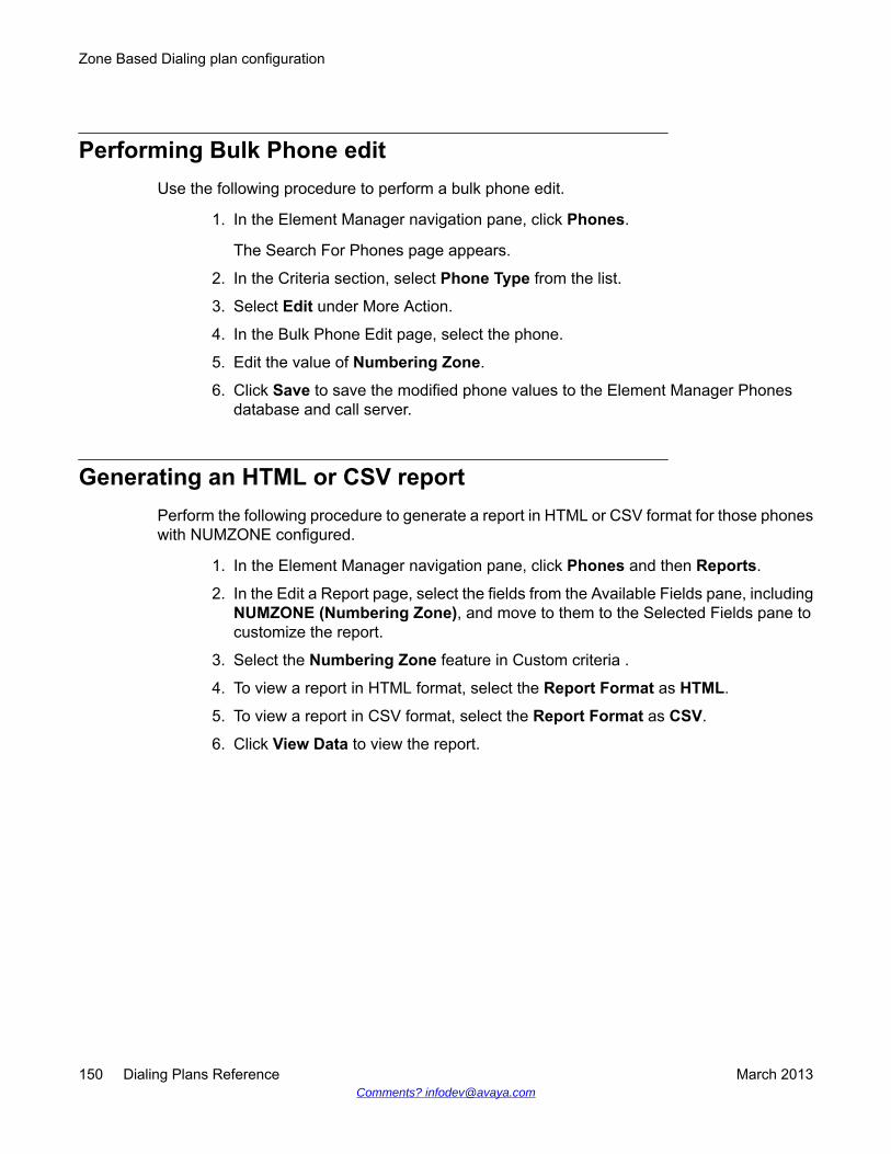
Performing Bulk Phone editUse the following procedure to perform a bulk phone edit.
1. In the Element Manager navigation pane, click Phones.
The Search For Phones page appears.
2. In the Criteria section, select Phone Type from the list.
3. Select Edit under More Action.
4. In the Bulk Phone Edit page, select the phone.
5. Edit the value of Numbering Zone.
6. Click Save to save the modified phone values to the Element Manager Phonesdatabase and call server.
Generating an HTML or CSV reportPerform the following procedure to generate a report in HTML or CSV format for those phoneswith NUMZONE configured.
1. In the Element Manager navigation pane, click Phones and then Reports.
2. In the Edit a Report page, select the fields from the Available Fields pane, includingNUMZONE (Numbering Zone), and move to them to the Selected Fields pane tocustomize the report.
3. Select the Numbering Zone feature in Custom criteria .
4. To view a report in HTML format, select the Report Format as HTML.
5. To view a report in CSV format, select the Report Format as CSV.
6. Click View Data to view the report.
Zone Based Dialing plan configuration
150 Dialing Plans Reference March 2013Comments? [email protected]
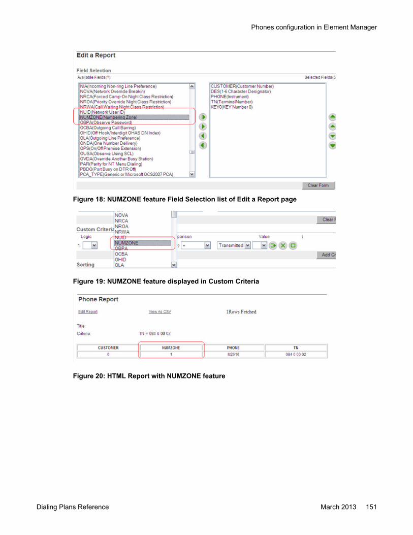
Figure 18: NUMZONE feature Field Selection list of Edit a Report page
Figure 19: NUMZONE feature displayed in Custom Criteria
Figure 20: HTML Report with NUMZONE feature
Phones configuration in Element Manager
Dialing Plans Reference March 2013 151

Figure 21: CSV Report with NUMZONE feature
Moving a phone with Numbering Zone configurationPerform the following procedures to swap or move phones with NUMZONE configured.
1. In the Navigation pane, click Phones.
The Search For Phones page appears.
2. In theCriteria section, select a phone with the Numbering Zone configured.
3. Click Move on the More Action list.
4. Enter an unused TN in the targeted field to move the phone to the target TN andupdate the values in the Element Manager Phones database.
The phone is moved to the target TN and the values are updated in the ElementManager Phones database.
Swapping a phone with Numbering Zone configuration
1. In the Element Manager navigation pane, select Phones.
The Search For Phones page appears.
2. In the Criteria section, select a phone with the Numbering Zone configured andanother phone without Numbering Zone configured.
3. Click Swap on the More Action list to swap the phones and update the values inthe Element Manager Phones database.
Zone Based Dialing plan configuration
152 Dialing Plans Reference March 2013Comments? [email protected]

Enabling the Numbering Zone option on a phonePerform the following procedure to enable the Numbering Zone option when adding aphone.
1. In the Element Manager navigation pane, select Phones.
The Search For Phones page appears.
2. In the Phones section, click Add .
The New Phones page appears.
3. In the Type section , select a Phone Type from the list, for example, 1110 - Avaya1110 IP Deskphone.
4. In the Options section, Select the Default value for ZONE check box to enable theNumber Zone.
5. Click Preview.
Disabling the Numbering Zone option for unsupported phones(VOLO)
Perform the following procedure to disable the Numbering Zone option for unsupportedphones.
1. On the Element Manager navigation pane,clickPhones.
The Search For Phones page appears.
2. In the Phones section, click Add.
The New Phones page appears.
3. In the Phone Type field, select the unsupported phone type, VOLO - IP PhoneVOLO from the list.
4. Clear the Default value for ZONE check box to disable the Number Zone.
Adding a phone with NUMZONE configured throughCommunication Server 1000 CLI
Perform the following procedures to add, edit, or delete a phone with NUMZONE configuredthrough Communication Server 1000 CLI.
1. In the Element Manager navigation pane, select Phones.
Phones configuration in Element Manager
Dialing Plans Reference March 2013 153

The Search For Phones page appears.
2. Click Retrieve.
The Retrieve options page appears.
3. Click All phones and reconcile and click Submit.
4. Complete the following from the CLI:
• Enable alarm in LD 117 using set open_alarm port address.
• Configure one or more of the new IP, Analog, or TDM phones.
Important:The management trap generated by Communication Servers 1000 is saved inElement Manager Phones and the database is updated accordingly. The newphone is displayed along with the other phones on the Search for Phonespage.
Editing a phone with NUMZONE configured through Avaya CS1000CLI
1. In the navigation pane, select Phones.
The Search for Phones page appears.
2. Click Retrieve.
3. Click All phones and reconcile.
4. Perform the following from the CLI:
• Enable alarm in LD 117 using set open_ alarm port address.
• Edit a configured IP, Analog, or TDM phone.
Important:The management trap generated by Avaya Communication Servers 1000 issaved in Element Manager Phones and the database is updated accordingly. Themodifications performed on the phone are displayed for the corresponding phonelisted in the Search for Phones page.
Deleting a phone with NUMZONE configured through CS1000 CLI
1. In the navigation pane, select Phones.
Zone Based Dialing plan configuration
154 Dialing Plans Reference March 2013Comments? [email protected]
The Search for Phones page appears.
2. Click Retrieve.
3. Click All phones and reconcile.
4. Perform the following in the CLI:
• Enable alarm in LD 117 using set open_ alarm port address.
• Delete a configured IP, Analog, or TDM phone.
Important:The management trap generated by Communications Server 1000 is received inElement Manager Phones and the database is updated accordingly. The deletedphone is removed from the list of phones in the Search for Phones page.
E.164 dial plan configuration
IntroductionFor information about Outgoing OC client SIP Gateway call to On-net E.164 number using IPWAN, Outgoing SIP CTI OC client call to On-net E.164 number using IP WAN, and OutgoingSIP CTI call from IP phone to On-net E.164 number using IP WAN, see Converged OfficeFundamentals — Microsoft Office Communications Server 2007, NN43001-121.
The following examples show dial plan configurations for Zone Based Dialing (ZBD).
AC1 and AC2 tablesEach call server has an AC1 and AC2 table for storing the configuration of E.164 call routing.The AC1 and AC2 access codes are configured in overlay 86. For example, at the Bellevillesite, the access code for local numbers is configured to 9 and the access code for dialing longdistance is configured to 6. The access codes can be different at other sites. For example, inthe UK, the access code for calling the PSTN is usually configured as 0. Therefore, accesscodes configured in overlay 86 for AC1 and AC2 can be different.
Configure AC1 = 9, AC2 = 6 for zone 2:
CHG ZPARM 2 AC1 9
CHG ZPARM 2 AC2 6
E.164 dial plan configuration
Dialing Plans Reference March 2013 155
To allow sites to use the local access codes, such access codes are configured in the ZBDnumbering zone parameters and ZFDP configurations, as shown in the following example.
Configure Routing Data for AC1 and AC2:
CHG ZFDP 2 601 INTL ‘Belleville International Dialing Prefix’
CHG ZFDP 2 61 NPA ‘Belleville NPA Dialing Prefix’
CHG ZFDP 2 9 NXX ‘Belleville Local PSTN Dialing Prefix’
For example, the access code <AC1> for local numbers is configured to 9 so when the accesscode 9 is dialed from the Belleville site, the system replaces the 9 with the system AC1 andprocesses the call using the AC1 table configuration, as configured in overlay 86.
ZFDP
The following ZFDP types are available for the E.164 dial plan:
INTL - International E.164 number - insert system AC1/AC2 to dialedstring
REG1 - Regional Level 1 - insert system AC1/AC2 + ZCC to dialed string
NPA - North American NPA - insert system AC1/AC2 + 1 to dialed string
REG2 - Regional Level 2:
DAC = 0 - insert system AC1/AC2 + ZCC to dialed string
DAC = 1 - insert system AC1/AC2 + ZCC + ZNPA to dialed string
NXX - North American NXX:
DAC = 0 - insert system AC1/AC2 + 1 to dialed string
DAC = 1 - insert system AC1/AC2 + 1 + ZNPA to dialed string
SPN - Special Number - insert system AC1/AC2 + replacement stringto dialed string
DAC: Delete Area Code
DAC is used to specify the style for local dialing and CLID building for a correspondingnumbering zone.
NPA-NXX-XXXX (10-digit dialing) is used in North America
NXX-XXXX (7-digit dialing) is used outside of North America
If DAC is configured to 1 for a numbering zone, NXX-XXXX is dialedand NXX-XXXX displays during an incoming local call.
Zone Based Dialing plan configuration
156 Dialing Plans Reference March 2013Comments? [email protected]

INACINAC is a prompt in overlay 16 for trunk route configuration. If it is configured to "YES", theAC1 or AC2 code is automatically added to the number of an incoming call over this trunkroute. The call is processed according to the AC1 or AC2 table configuration.
The system knows which access code it has to add based on the customer NET dataconfiguration in overlay 15. The following example (customer NET data printed in overlay 21)shows that the number of incoming NXX, NPA, INTL, LOC calls are added with AC1 and SPNwith AC2.
AC1 INTL NPA NXX LOC
AC2 SPN
Avaya recommends that INAC be configured to "YES".
E.164 International format in dial plan configurationsUsers dial numbers in the E.164 local, national, or international format depending on wherethe destinations are. With a central deployment that covers call routing for many countries, thelocal or national format is not unique. Therefore, call routing is configured with the E.164international format which includes the country code, area or city code, and local exchange.
In the following example, ZBD changes an E.164 local or national number to an E.164international number. A user dials the local number 96139661234. ZBD determines from thecaller’s numbering zone ZFDP configuration that 9 is for local access. The country code isretrieved from the numbering zone configuration and adds it to the destination number, makingit an E.164 international number (from 6139661234 to 16139661234). The 9 is also replacedby the system AC1 and the resulting number is <AC1>16139661234. The call is thenprocessed with the AC1 table configuration SPN 1613. Calls between call servers are alwaysE.164 international calls and can be uniquely identified by the destination call server.
Basic dial plan configuration conceptsWhen a number is dialed internally or received over an incoming trunk by the call server, thesystem tries to find a match for the number by searching the following tables:
DN table configured in overlay 10, 11 and 12 for local termination
CDP table configured in overlay 87 for routing to another call server in CDP calltype
E.164 dial plan configuration
Dialing Plans Reference March 2013 157

AC1 and AC2tables
configured in overlay 90 for routing UDP calls such as E.164 calls toPSTN or ESN calls
AC1 and AC2 codes must be configured in overlay 86 and they must prefix the dialed digits.For example, the "9" in 916139661234 is the AC1 or AC2 code. The system searches the AC1or AC2 table when a number begins with this access code. Otherwise, it searches the DN andthe CDP tables.
For the E.164 AC1 and AC2 table configurations, different prefixes can be configured withdifferent call type commands. For example, the following prefix can be configured in overlay90 to route 16139661234 as a national number from Houston to Belleville:
SPN 1613
There are a number of things that must be entered for this configuration for routing numberswith this prefix. The most important is the number for the route list that tells the system how toroute the call. The route list is configured in overlay 86 which provides a trunk route numberto route the call. It also provides the flexibility for changing the number before sending it to thetrunk. The following shows the key data in a route list block:
RLI 2
ENTRY 0
LTER = NO
ROUT 17 (trunk route number)
DMI 3
They are described as follows:
DMI—The DMI number points to the DMI configuration in overlay 86 which has the followingkey data:
DMI 3
DEL 7 (delete 7 digits)
INST 6343 (insert 6343 in front of the number)
CTYP LOC (specify call type = location code for ESN routing)
Important:When you use a DMI for outgoing calls it guarantees that non-call associated messages(Ring Again, Network ACD) fail. Ensure that all such services are local to the high capacityCommunication Server 1000.
Zone Based Dialing plan configuration
158 Dialing Plans Reference March 2013Comments? [email protected]

LTER—LTER stands for local termination. If it is configured to "YES", the call is meant to beterminated locally and a trunk route is not needed. It is also used to pass the routing of thenumber to another dial plan configuration.
ENTR—ENTR stands for entry. This allows multiple entries of route data in the route list blockso that if a call fails with the first entry, it is attempted again with the second entry and so on.
The following is a typical example:
SPN1613
RLI 1
ENTRY 0
LTER = YES
DEL 7
INST 6343
CTYP = LOC
E.164 configuration for calls in the same call serverE.164 numbers are usually processed against the AC1/AC2 table configurations in overlay 90.For example, an SPN is configured in overlay 90 as follows to route an E.164 number thatstarts with 1613 to the PSTN:
SPN 1613
RLI 1
ENTRY 0
Route 1 (route over PRI trunk to PSTN or over VRTK to GW to PSTN)
With the ZBD public dial plan, 1613xxxxxxx can be a DID number with its corresponding seven-digit internal DN configured in the call server. The configuration must recognize this and routeit accordingly. To achieve this, the Alternate Routing Remote Number (ARRN) forSupplementary Digit Restriction and Recognition (SDRR) is used. ARRN is set equal to theprefix of the DID number so that if the dialed digits match this prefix the number is changed tothe internal seven-digit DN and terminate locally. ARRN matching is processed first, althoughthe configuration is performed at the end. The following example is a configuration to recognize16139612xxx as the DID range for the Belleville site and is converted to the internal seven-digit for local termination:
SPN 1613
E.164 dial plan configuration
Dialing Plans Reference March 2013 159
RLI 1
ENTRY 0
Route 1(route overPRI trunk toPSTN orover VTRKto GW toPSTN)
ARRN 9612
RLI 11
ENTRY 0
LTER — YES
DEL 7
INST 343 (resulting number is 3432xxx)
If 16139612220 is dialed, the ARRN matching will find that the number matches the DID range9612xxx. It will terminate locally by deleting the E.164 prefix and insert the site prefix resultingin the corresponding seven-digit internal DN 3432220. See Figure 22: intersite call flow withinthe same call server on page 161.
Zone Based Dialing plan configuration
160 Dialing Plans Reference March 2013Comments? [email protected]

Figure 22: intersite call flow within the same call server
E.164 configuration for calls to different call serversWith multiple call servers, E.164 calls could be going to a site in a different call server. The dialplan configuration must recognize that a dialed number is to be terminated in another callserver. To achieve this, all on-net E.164 numbers must entered into the NRS database as E.164International numbers. The dial plan configuration is performed so that the NRS database issearched to see if the E.164 number exists. If the number exists, the call is routed as anInternational call to the other call server. Otherwise, it will try the next route entry to send thecall to the PSTN. The configuration is as follows:
SPN 1613
RLI 2
ENTRY0
Route 2 (route over VTRK/NRS as E.164 International callto other call server for on-net calls)
DEL none
INST none
E.164 dial plan configuration
Dialing Plans Reference March 2013 161
CTYP = INTL
Entry 1
Route 1 (route over PRI trunk to PSTN or over VTRK to GWto PSTN)
Avaya does not recommend sending calls between call servers with CDP call type. This wouldrequire every call server to know all the internal DNs on other call servers. Dial planconfigurations would have to be added to every existing call server when a new call server isadded to the network. With E.164 International call type, the major routing configurations fora new call server would be entered into the NRS only. Therefore, Avaya recommends sendingcalls between call servers with E.164 International call type. See Figure 23: intersite call flowbetween call servers on page 163.
Important:If you use this provisioning, unless the Signaling Server settings are correct, any numberrouted to the NRS that is not found results in a cause code 1, and cause code 1 cannotreach entry 1. Ensure that the check box for the cause code 1 to enable MALT on thesignalling server for this cause code, is configured to Enabled.
For information about VNR over IP, see IP Peer Networking Installation and Commissioning,NN43001-313.
Zone Based Dialing plan configuration
162 Dialing Plans Reference March 2013Comments? [email protected]
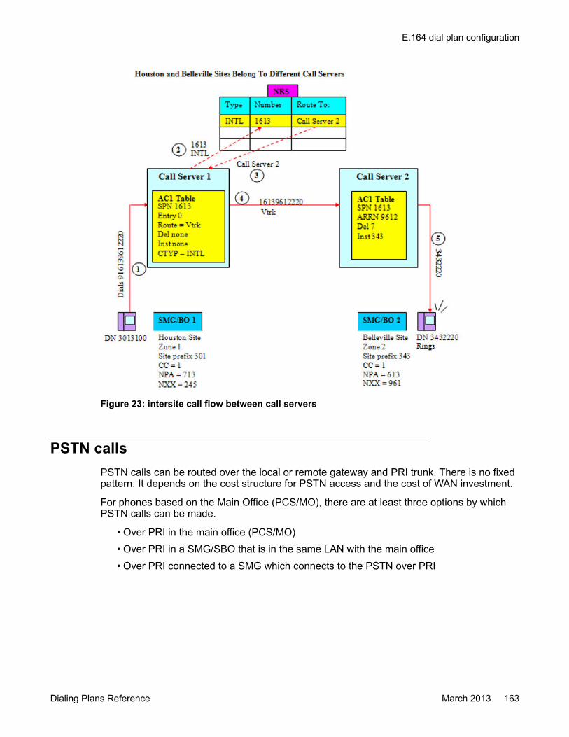
Figure 23: intersite call flow between call servers
PSTN callsPSTN calls can be routed over the local or remote gateway and PRI trunk. There is no fixedpattern. It depends on the cost structure for PSTN access and the cost of WAN investment.
For phones based on the Main Office (PCS/MO), there are at least three options by whichPSTN calls can be made.
• Over PRI in the main office (PCS/MO)• Over PRI in a SMG/SBO that is in the same LAN with the main office• Over PRI connected to a SMG which connects to the PSTN over PRI
E.164 dial plan configuration
Dialing Plans Reference March 2013 163
For routing within the same call serverFor routing within the same call server, the proper site prefix is added to the dialed number forrouting it to another SPN for further processing. Two extra zeroes are added in front of the siteprefix to avoid conflicts with other numbers in the SPN and NRS configurations.
The following example shows the configuration for routing to the PSTN over the remotegateway/PRI trunk first. If this fails, routing over the local gateway is attempted.
SPN 1613
RLI 1
ENTRY 0
LTER = YES
DEL none
INST <AC1/AC2>00343 (to route PSTNcalls over the remote PRI trunk or GW)
Entry 1
LTER = YES
DEL none
INST <AC1/AC2>00p ("p" automaticallyinserts the site prefix of the originating partyfor routing PSTN calls over the local PRItrunk or GW)
ARRN 9612
RLI 11
Entry 0
LTER = YES
DEL 7 digits
INST 343 (resulting number is 3432220 forlocal termination)
For routing to a different call serverThe following examples shows routing calls to a different call server.
SNP 1613
Zone Based Dialing plan configuration
164 Dialing Plans Reference March 2013Comments? [email protected]

RLI 2
ENTRY 0
Route 2 (route over VTRK/NRS as E.164 Internationalcall to other call servers for on-net calls)
DEL none
INST none
CTYP = INTL
Entry 1
Route 2 (route over VTRK/NRS as SPN call to other callserver for remote breakout to PSTN)
DEL none
INST 00343
CTYP = SPN
Entry 2
LTER = YES
DEL none
INST 343 <AC1/AC2>00p (“p” automatically inserts thesite prefix of the originating party for routing PSTN callsover the local PRI trunk or GW)
Further processing of PSTN calls: sending PSTN calls over localPRI trunks
See Figure 24: PSTN call flow with SMG sites belonging to the same call server on page 167and Figure 26: PSTN call flow with SMG sites belonging to a different call server onpage 169.
SPN 00301 (forsending PSTNcalls fromHouston site)
RLI 3
Entry 0
Route 1 (route over PRI trunk to PSTN)
DEL 6
E.164 dial plan configuration
Dialing Plans Reference March 2013 165
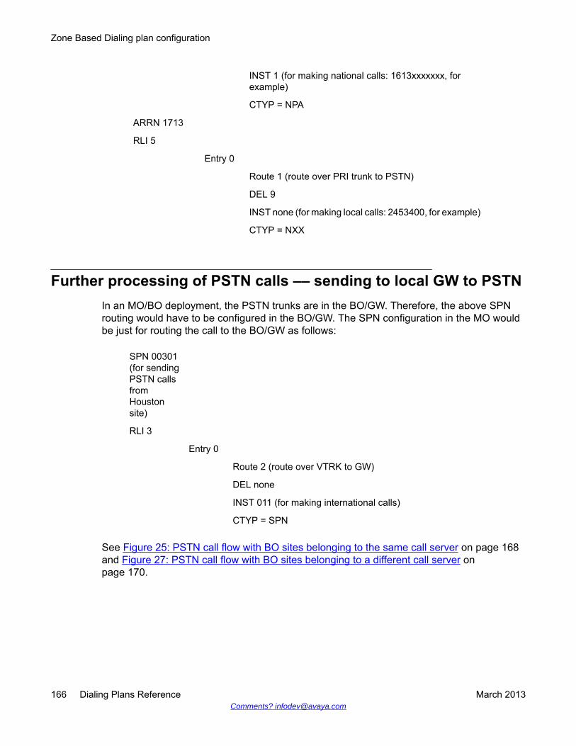
INST 1 (for making national calls: 1613xxxxxxx, forexample)
CTYP = NPA
ARRN 1713
RLI 5
Entry 0
Route 1 (route over PRI trunk to PSTN)
DEL 9
INST none (for making local calls: 2453400, for example)
CTYP = NXX
Further processing of PSTN calls –– sending to local GW to PSTNIn an MO/BO deployment, the PSTN trunks are in the BO/GW. Therefore, the above SPNrouting would have to be configured in the BO/GW. The SPN configuration in the MO wouldbe just for routing the call to the BO/GW as follows:
SPN 00301(for sendingPSTN callsfromHoustonsite)
RLI 3
Entry 0
Route 2 (route over VTRK to GW)
DEL none
INST 011 (for making international calls)
CTYP = SPN
See Figure 25: PSTN call flow with BO sites belonging to the same call server on page 168and Figure 27: PSTN call flow with BO sites belonging to a different call server onpage 170.
Zone Based Dialing plan configuration
166 Dialing Plans Reference March 2013Comments? [email protected]
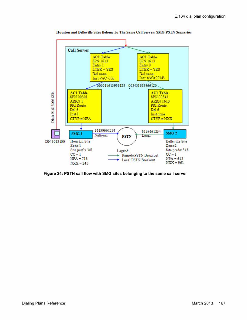
Figure 24: PSTN call flow with SMG sites belonging to the same call server
E.164 dial plan configuration
Dialing Plans Reference March 2013 167
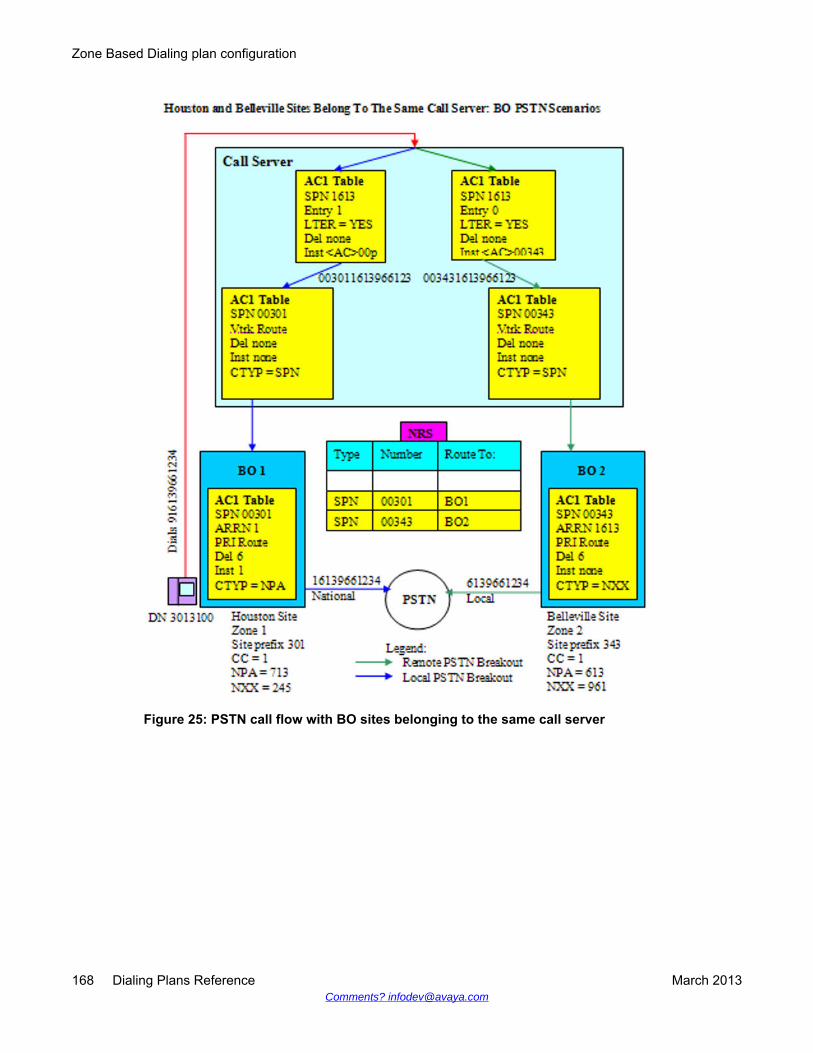
Figure 25: PSTN call flow with BO sites belonging to the same call server
Zone Based Dialing plan configuration
168 Dialing Plans Reference March 2013Comments? [email protected]
Figure 26: PSTN call flow with SMG sites belonging to a different call server
E.164 dial plan configuration
Dialing Plans Reference March 2013 169

Figure 27: PSTN call flow with BO sites belonging to a different call server
ESA callsThe challenge for provisioning ESA calls for a central deployment is that there are not enoughESDNs available for addressing the need of different ESDNs for a large number of sites. Therehad been only one ESDN available for each system. The number was increased to 16 sinceRelease 5.0 but is still not enough for larger deployments.
To resolve this issue, some digit manipulation is required. One ESDN is configured with anumber that is not a real emergency number and is not conflicting with other DNs, 111 for
Zone Based Dialing plan configuration
170 Dialing Plans Reference March 2013Comments? [email protected]
example. Then, when a local emergency number is dialed (911, 999, 112, and so on) it isconverted to 111 and the ESA processing engages. Based on the ERL number configured forthe originating phone, the route list is retrieved from the corresponding ERL table. In that routelist, 111 is changed back to the local emergency number before it is sent to the PSAP. Theprocess is illustrated in the following example:
Call scenario: Dial local ESN 911 from DN 3013100 Houston.
1. Configure ESA with ESDN = 111 in LD 24
2. Configure ESDN conversion in the ZFDP table from 911 to 111 for the originatingsite
Chg ZFDP 1 911 ESDN 111 LEN 3 ‘Houston Emergency Services DN”
3. Configure a route list in LD 86 as follows. This route list is going to be entered inthe ERL table for routing the ESA call over a trunk.
RLI 8
Route 3 (route to PSAP)
DEL 3
INST <AC1/AC2>911
For routing the call to a gateway, the route list is configured as follows:
RLI 8
Route 2 (route over VTRK to GW)
DEL none
INST 00301
The call is routed to the gateway (GW) as 00301111. The GW converts the numberto 911 with the following SPN:
SPN 00301111
RLI 9
LTER = YES
DEL 8
INST 911
911 is configured in the GW as an Emergency Service DN (ESDN) and the call isrouted to the Public Safety Answering Point (PSAP).
E.164 dial plan configuration
Dialing Plans Reference March 2013 171
E.164 enhancements for Office Communications Server 2007Office Communications Server (OCS) integration refers to full coexistence between an existingPBX and the Enterprise Voice infrastructure thus providing a flexible and powerful combinationof traditional telephony and software-powered VoIP. With OCS integration, all users in anorganization can make and receive phone calls by using their existing desktop PBX phone,Office Communicator 2007, or another SIP client, such as the Office Communicator PhoneEdition.
For calls from the call server to the Office Communicator client, the usual mechanism is usedand no specific configuration is required for the ZBD feature.
For calls to the OC client, NRS routes a call from the call server to the appropriate OCS Proxyserver with MCM to define the user. The seven-digit DN is converted into E.164 format beforesending a call to the OC client.
For incoming calls in Computer mode to the OC, the CLID appears in E.164 internationalformat. For incoming calls in Phone mode to the OC client, the OC receives the call from thePSTN, the CLID is displayed in E.164 international format even if the caller is in the same areaor country.
For calls from the OC client to the call server, changes are made in SIP messages to definethe destination phone. INVITE URI contains the E.164 number to use common SPN blocks inthe call server.
OCS users must have a DID number; internal non-DID numbers cannot be used here. This isapplicable for SIP Gateway services and remote call control.
For more information about this enhancement, see Avaya Converged Office -- Microsoft OfficeCommunications Server 2007 Fundamentals, NN43001-121.
Outgoing SIP CTI call from IP phone to on-net E.164 number usingIP WAN
Within an outgoing SIP CTI call from IP phone to on-net E.164 number using IP WAN scenario,the following occurs in order:
1. The IP phone user dials an E.164 number.
2. The ZONE Prefix is inserted, based on the numbering zone configuration, for alldialed digits. MCM and the Proxy Server process the call and send it to the OCclient. The Prefix (PREF) avoids the necessity for the Pretranslation tableconfiguration.
Zone Based Dialing plan configuration
172 Dialing Plans Reference March 2013Comments? [email protected]
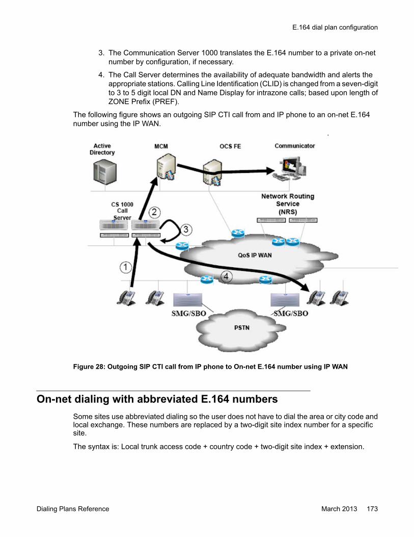
3. The Communication Server 1000 translates the E.164 number to a private on-netnumber by configuration, if necessary.
4. The Call Server determines the availability of adequate bandwidth and alerts theappropriate stations. Calling Line Identification (CLID) is changed from a seven-digitto 3 to 5 digit local DN and Name Display for intrazone calls; based upon length ofZONE Prefix (PREF).
The following figure shows an outgoing SIP CTI call from and IP phone to an on-net E.164number using the IP WAN.
Figure 28: Outgoing SIP CTI call from IP phone to On-net E.164 number using IP WAN
On-net dialing with abbreviated E.164 numbersSome sites use abbreviated dialing so the user does not have to dial the area or city code andlocal exchange. These numbers are replaced by a two-digit site index number for a specificsite.
The syntax is: Local trunk access code + country code + two-digit site index + extension.
E.164 dial plan configuration
Dialing Plans Reference March 2013 173
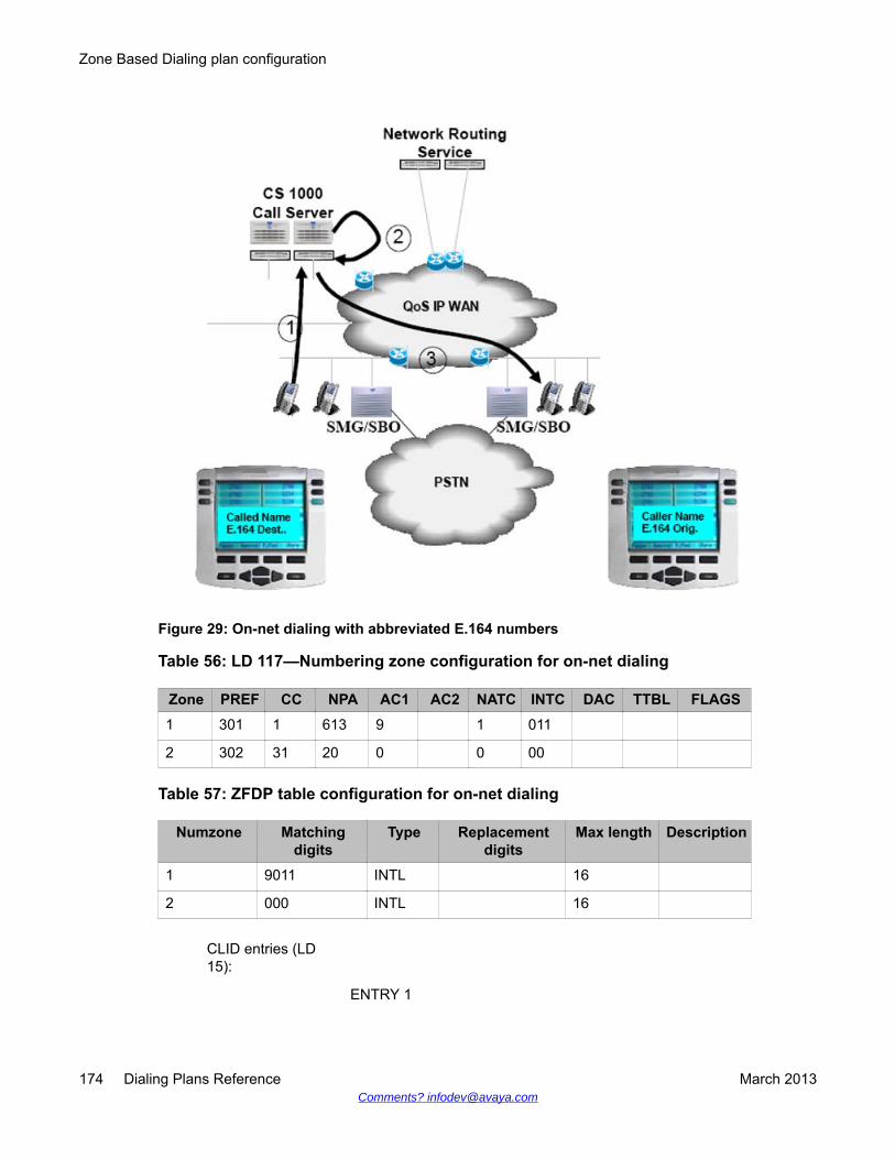
Figure 29: On-net dialing with abbreviated E.164 numbers
Table 56: LD 117—Numbering zone configuration for on-net dialing
Zone PREF CC NPA AC1 AC2 NATC INTC DAC TTBL FLAGS1 301 1 613 9 1 011
2 302 31 20 0 0 00
Table 57: ZFDP table configuration for on-net dialing
Numzone Matchingdigits
Type Replacementdigits
Max length Description
1 9011 INTL 16
2 000 INTL 16
CLID entries (LD15):
ENTRY 1
Zone Based Dialing plan configuration
174 Dialing Plans Reference March 2013Comments? [email protected]
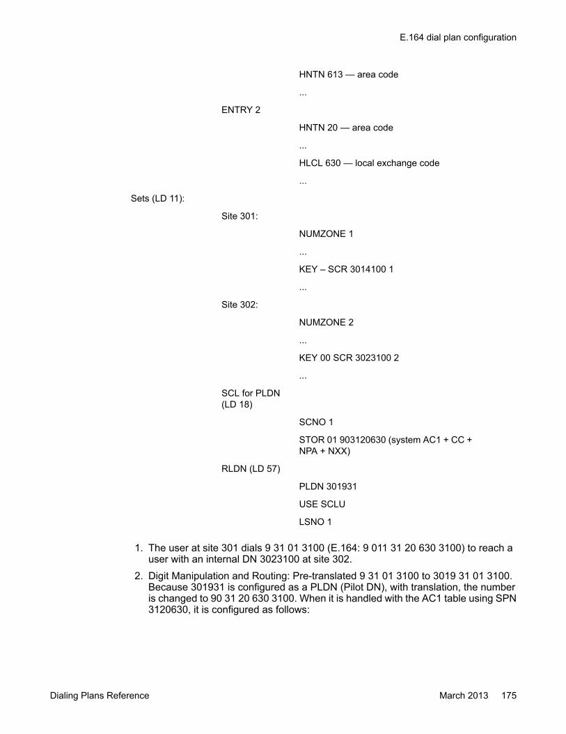
HNTN 613 — area code
...
ENTRY 2
HNTN 20 — area code
...
HLCL 630 — local exchange code
...
Sets (LD 11):
Site 301:
NUMZONE 1
...
KEY – SCR 3014100 1
...
Site 302:
NUMZONE 2
...
KEY 00 SCR 3023100 2
...
SCL for PLDN(LD 18)
SCNO 1
STOR 01 903120630 (system AC1 + CC +NPA + NXX)
RLDN (LD 57)
PLDN 301931
USE SCLU
LSNO 1
1. The user at site 301 dials 9 31 01 3100 (E.164: 9 011 31 20 630 3100) to reach auser with an internal DN 3023100 at site 302.
2. Digit Manipulation and Routing: Pre-translated 9 31 01 3100 to 3019 31 01 3100.Because 301931 is configured as a PLDN (Pilot DN), with translation, the numberis changed to 90 31 20 630 3100. When it is handled with the AC1 table using SPN3120630, it is configured as follows:
E.164 dial plan configuration
Dialing Plans Reference March 2013 175

SPN 3120630(country code +city code + localexchange)
ARRN 3
LTER YES
DMI
DEL 7
INST 302
The number above is changed to 30231003. The Call Server determines the availability of adequate bandwidth and alerts the
appropriate stations.
ZFDP configurationZFDP configuration allows manipulation of digits dialed from an IP Phone if the existing DN inthe DN tree (including NARS DN) does not correspond. By configuring ZFDP, you can decreasethe size of the CDP table (LD 87) and AC1/AC2 table (LD 90).
The following sections contain ZFDP configuration examples to provide an understanding ofhow ZFDP works.
The system AC1 /AC2 code in the following examples is 90. When an international call is made,access code + international code is replaced by a system access code, so the appropriateSPN block can be found.
When a national call is made, access code + national code is replaced by a system accesscode + CC value from NUMZONE, so the number gets normalized, as it does for aninternational call, and the appropriate SPN block can be found.
When local subscriber call is made, the access code is replaced by a system access code +CC value from NUMZONE (when DAC is 1 in NUMZONE) or the access code is replaced bya system access code + CC + NPA value from NUMZONE (when DAC is 0 in NUMZONE), sothe number gets normalized, as it does for an international call, and appropriate SPN blockcan be found.
The difference between NPA and REG1, and NXX and REG2 is that the country code for NPAand NXX is to be 1. Thus, CC is 1 in the NUMZONE configuration for NPA/NXX.
Zone Based Dialing plan configuration
176 Dialing Plans Reference March 2013Comments? [email protected]

E.164 dial planThe E.164 dial plan numbers are dialed with the following access codes:
• International call: access code + international code + international number (CC + NPA +NXX + DN)
• National call: access code + national code + national number (NPA + NXX + DN)
• Local subscriber call: access code + local subscriber number (North America: NPA + NXX+ DN, when DAC is 0 in NUMZONE; Europe: NXX + DN, when DAC is 1 in NUMZONE)
To decrease the amount of ESN blocks to process calls, all dialed numbers are normalizedinto an E.164 international number, for example, only one SPN is used, SPN CC+NPA+NXX.
For normalization a ZFDP entry is created.
For example in North America the following ZFDP entry is created:
• International call: ZFDP x access_code+international_code INTL
• National call: ZFDP x access_code+national_code NPA
• Local subscriber call: ZFDP x access_code NXX
When an international call is made, access code + international code is replaced by systemaccess code, so an appropriate SPN block is found.
When a national call is made, access code + national code is replaced by system access code+ 1, so the number gets normalized, as it does for an international call, and an appropriateSPN block can be found.
When local subscriber call is made, the access code is replaced by a system access code +1 + NPA value from NUMZONE (when DAC is 0 in NUMZONE) or the access code is replacedby a system access code + 1 (when DAC is 1 in NUMZONE), so the number gets normalized,as it does for an international call, and appropriate SPN block can be found.
For example in Europe the following ZFDP entry is created:
• International call: ZFDP x access_code+international_code
• INTL National call: ZFDP x access_code+national_code REG1
• Local subscriber call: ZFDP x access_code REG2
E.164 dial plan configuration
Dialing Plans Reference March 2013 177
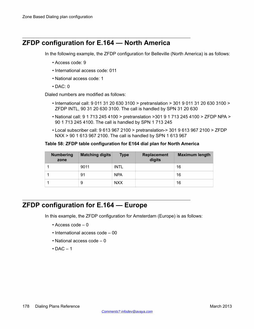
ZFDP configuration for E.164 — North AmericaIn the following example, the ZFDP configuration for Belleville (North America) is as follows:
• Access code: 9
• International access code: 011
• National access code: 1
• DAC: 0
Dialed numbers are modified as follows:
• International call: 9 011 31 20 630 3100 > pretranslation > 301 9 011 31 20 630 3100 >ZFDP INTL, 90 31 20 630 3100. The call is handled by SPN 31 20 630
• National call: 9 1 713 245 4100 > pretranslation >301 9 1 713 245 4100 > ZFDP NPA >90 1 713 245 4100. The call is handled by SPN 1 713 245
• Local subscriber call: 9 613 967 2100 > pretranslation-> 301 9 613 967 2100 > ZFDPNXX > 90 1 613 967 2100. The call is handled by SPN 1 613 967
Table 58: ZFDP table configuration for E164 dial plan for North America
Numberingzone
Matching digits Type Replacementdigits
Maximum length
1 9011 INTL 16
1 91 NPA 16
1 9 NXX 16
ZFDP configuration for E.164 — EuropeIn this example, the ZFDP configuration for Amsterdam (Europe) is as follows:
• Access code – 0
• International access code – 00
• National access code – 0
• DAC – 1
Zone Based Dialing plan configuration
178 Dialing Plans Reference March 2013Comments? [email protected]
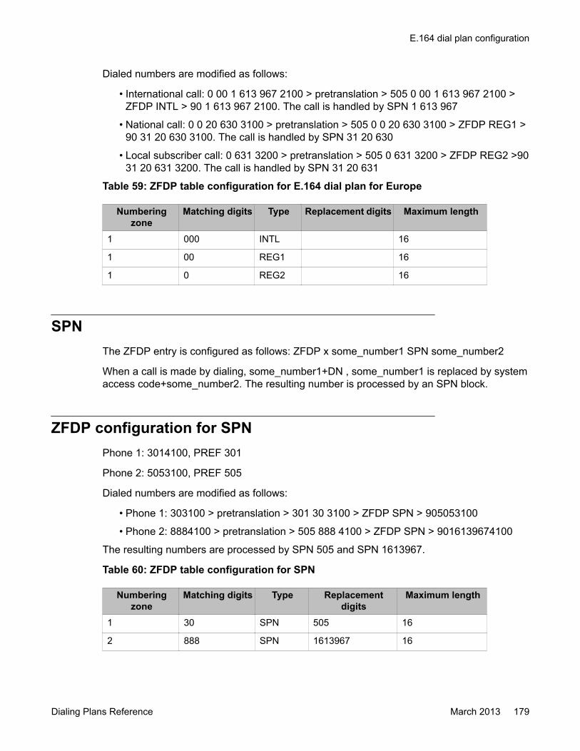
Dialed numbers are modified as follows:
• International call: 0 00 1 613 967 2100 > pretranslation > 505 0 00 1 613 967 2100 >ZFDP INTL > 90 1 613 967 2100. The call is handled by SPN 1 613 967
• National call: 0 0 20 630 3100 > pretranslation > 505 0 0 20 630 3100 > ZFDP REG1 >90 31 20 630 3100. The call is handled by SPN 31 20 630
• Local subscriber call: 0 631 3200 > pretranslation > 505 0 631 3200 > ZFDP REG2 >9031 20 631 3200. The call is handled by SPN 31 20 631
Table 59: ZFDP table configuration for E.164 dial plan for Europe
Numberingzone
Matching digits Type Replacement digits Maximum length
1 000 INTL 16
1 00 REG1 16
1 0 REG2 16
SPNThe ZFDP entry is configured as follows: ZFDP x some_number1 SPN some_number2
When a call is made by dialing, some_number1+DN , some_number1 is replaced by systemaccess code+some_number2. The resulting number is processed by an SPN block.
ZFDP configuration for SPNPhone 1: 3014100, PREF 301
Phone 2: 5053100, PREF 505
Dialed numbers are modified as follows:
• Phone 1: 303100 > pretranslation > 301 30 3100 > ZFDP SPN > 905053100
• Phone 2: 8884100 > pretranslation > 505 888 4100 > ZFDP SPN > 9016139674100
The resulting numbers are processed by SPN 505 and SPN 1613967.
Table 60: ZFDP table configuration for SPN
Numberingzone
Matching digits Type Replacementdigits
Maximum length
1 30 SPN 505 16
2 888 SPN 1613967 16
E.164 dial plan configuration
Dialing Plans Reference March 2013 179

ZFDP ESDN for ESA callsThe ZFDP ESDN entry can be configured to use many ESA DNs for different NUMZONESand process the ESA DN from VOLO IP Phone. Only ESA DN is allowed from VOLO IP Phone,thus, ZFDP ESDN is selected in this case.
The ZFDP ESDN entry is configured as follows:
ZFDP x ESA_DN1 ESDN SYS_ESA_DN LEN y
When ESA_DN1 is dialed, it is replaced by SYS_ESA_DN.
ZFDP configuration for ESDNSystem ESA DN: 112, 911
Phone 1: 3014100, PREF 301, ESA DNs for this site are 112, 01
Phone 2: 5053100, PREF 505, ESA DNs for this site are 112, 911
Dialed numbers are modified as follows:
• Phone 1: 112 > pretranslation > 301112 > ZFDP ESDN-> 112
• Phone 1: 01 > pretranslation > 30101 > ZFDP ESDN ->112
• Phone 2: 112 > pretranslation > 505112 > ZFDP ESDN ->911
• Phone 2: 911 > pretranslation > 505911 > ZFDP ESDN ->911
Table 61: ZFDP table configuration for ESDN
Numberingzone
Matching digits Type Replacementdigits
Maximum length
1 112 ESDN 112 3
1 01 ESDN 112 2
2 112 ESDN 911 3
2 911 ESDN 911 3
Alternate Call RoutingAlternate Call Routing (ACR) is used when there is insufficient bandwidth or for unregisteredresources. Each zone must be configured with a ZALT prefix as defined in LD 117 for routing.The ZALT prefix uses the same configuration for ACR for insufficient bandwidth or forunregistered resources.
Zone Based Dialing plan configuration
180 Dialing Plans Reference March 2013Comments? [email protected]

The VPNI parameter in the Customer Data Block (CDB) should be configured to a non-zerovalue for ACR to work when there is insufficient bandwidth or for unregistered resources. If theVPNI parameter is not changed from the default value of zero (0), ACR does not work
Insufficient bandwidthIn situations where there is insufficient bandwidth to establish a call between two sites, the callis routed over the PSTN using the local PRI trunk or gateway and is then routed to the PRItrunk or gateway nearest to the other site. The terminating end point answers the call and avoice path is established between the two end points over the PSTN.
For an intersite calls, the usual NARS step-back-on-congestion mechanism engages if the callfails to connect due to insufficient bandwidth. The next entry in the route list, if configured todo so, routes the call over the PSTN.
For calls within the same call server where there is insufficient bandwidth, the call cannot bererouted using the usual step-back-on-congestion mechanism. An alternate route is configuredfor each zone with a ZALT prefix defined in LD 117 for routing the call.
Unregistered resourcesAlternate Call Routing (ACR) for unregistered resources is used for rerouting calls if theterminating resource, such as a telephone, is unregistered locally but is likely to be registeredelsewhere in the network, for example, an SMG in survival mode. The alternate route can bea PSTN resource or any other available network.
The Flexible Orbiting Prevention Timer (FOPT) is configured to prevent an infinite loop fromoccurring in the network. The FOPT defaults to six-seconds and blocks subsequent callredirections from occurring on that resource within the same six-second period. When ACR isblocked by Orbit Prevention, the “no answer” call processing treatment configured for thatresource such as Hunt or Call Forward No Answer (CFNA) is applied.
For example, in a situation where both locations are in survival mode and a call is made to anIP Phone that appears unregistered on the local SMG, the prefix is extracted from the ZALTtable and is appended to the dialed digits. The SMG reattempts to route the call using a routingentity, such as the PSTN, to the SMG where the destination IP Phone is likely to be registered.If the IP Phone is not registered on the target SMG and is redirected back to the local SMGwithin the FOPT timer period, Orbit Protection blocks this and any other redirections regardlessof their origin, and the “no answer” call processing treatment is applied.
Each zone on which ACR is enabled must have a ZALT prefix defined for routing calls. TheAlternate Prefix (ALTPrefix) is configured in LD 117 using the Zone Alternate Route (ZALT)command. ACR for unregistered resources is enabled or disabled in LD 117 by configuringUnreg ACR to Yes or No. FOPT is configured in LD 15 using the TIM_DATA command. TheFOPT input parameter must be even numbers between 0 and 30.
E.164 dial plan configuration
Dialing Plans Reference March 2013 181

Important:The Orbit Prevention feature is shared by Call Forward (CFW) and ACR for unregisteredresources. ACR for unregistered resources provides the same alternate routing functionalityas ACR for Network Bandwidth Management, see Insufficient bandwidth on page 181. ACRfor unregistered resources also applies in a High Scalability solution. For more informationabout High Scalability implementation recommendations, see Avaya Communication Server1000E Planning and Engineering — High Scalability Solutions, NN43041-221.
LD 117Configure the ZALT (Zone Alternate Route) prefix in LD 117, as shown below.
CHG ZALT <zone> <ALTPrefix> [<All calls>] [<Unreg ACR>]
Where:
• zone: is the property to be changed
• ALTPrefix: is a digit string of up to seven-digits that is appended as a prefix to the dialednumber. It is used for calls that cannot be routed through the WAN due to insufficientbandwidth, poor QoS, or the terminating resource is unregistered.
• All calls: is configured to Yes or No. It allows or denies Alternative Routing for the all callsubfeature. The parameter is optional and configured to No, by default.
• Unreg ACR: is configured to Yes or No. It enables Alternative Routing for the unregisteredresources subfeature. The parameter is optional and configured to No, by default.
When there is insufficient bandwidth for a call, the alternate prefix is inserted. For example, acall from 3013100 is placed to 3432220. 3432220 becomes <AC1/AC2>0003432220 and it isprocessed by the following SPN. The SPN restores the number to the E.164 format and routesto the PSTN.
RLI 17
LTER = YES
DEL 6 (delete the site prefix and the leading zeroes)
INST <AC1/AC2>00pc613961 (insert <AC1/AC2>, the originating siteprefix with extra zeroes, the terminating site country code, area code,and local exchange).
MO-BO modelConfiguration on the MO side:
1. Use SPN 1613 for calls between MO and MO.
Zone Based Dialing plan configuration
182 Dialing Plans Reference March 2013Comments? [email protected]

SPN 1613
RLI 2
Entry 0
Route 2 (route over VTRK/NRS as E.164International call to other Call Server foron-net calls)
DEL none
INST none
CTYP = INTL
Entry 1
Route 2 (route over VTRK/NRS as SPNcall to other Call Server for remotebreakout to PSTN)
DEL none
INST 00343
CTYP = SPN
Entry 2
LTER = YES
DEL none
INST <AC1/AC2> 00p (‘p’ automaticallyinserts the site prefix of the originatingparty for routing PSTN calls over the localPRI trunk or GW)
2. In case of insufficient bandwidth, use ZALT to insert digits and process a callproperly, routing to the PSTN. ZALT <zone #> <AC1/AC2>000.
3. Use SPN 000343 to restore a dialed number to E.164 format.
SPN 000343
RLI 7
LTER = YES
DEL 6 (delete the site prefix and the leading zeroes)
INST (<AC1/AC2>)00pc613961 (<AC1/AC2>), theoriginating site prefix with extra zeroes, the terminatingsite country code, area code and local exchange)
4. Use SPN 00301 to route a call to PSTN through a trunk located at MO or BO.
SPN 00301
E.164 dial plan configuration
Dialing Plans Reference March 2013 183

RLI 3
Entry 0
Route 2 (route over VTRK to GW)
DEL none
INST none
CTYP = SPN
Entry 1
Route 20 (route over PRI trunk located at MOto PSTN)
DEl 5
INST 011 (for making international calls)
CTYP = INTL
ARRN 1
RLS 4
Entry 0
Route 2 (route over VTRK to GW)
DEL none
INST none
CTYP = SPN
Entry 1
Route 1 (route over PRI trunk to PSTN)
DEL 6
INST 1 (for making national calls: forexample, 1613xxxxxxx)
CTYP = NPA
Entry 2
Route 10 (route over PRI trunk located atPCS/MO to PSTN)
DEL 6
INST 1 (for making national calls: forexample, 1613xxxxxxx)
CTYP = NPA
ARRN 1713
RLS 5
Zone Based Dialing plan configuration
184 Dialing Plans Reference March 2013Comments? [email protected]

Entry 0
Route 2 (route over VTRK to GW)
DEL none
INST none
CTYP = SPN
Entry 1
Route 1 (route over PRI trunk to PSTN)
DEL 9
INST none (for making local calls: forexample, 2453400)
CTYP = NXX
Entry 2
Route 10 (route over PRI trunk located atPCS/MO to PSTN)
DEL 9
INST none (for making local calls: forexample, 2453400)
CTYP = NXX
Configuration on the Branch Office (BO) side.
SPN 00301(for sendingPSTN callsfrom Houstonsite)
RLI 3
Entry 0
Route 1 (route over PRI trunk to PSTN)
DEL 1
INST 011 (for making international calls)
CTYP = INTL
ARRN 1
RLS 4
Entry 0
Route 1 (route over PRI trunk to PSTN))
E.164 dial plan configuration
Dialing Plans Reference March 2013 185
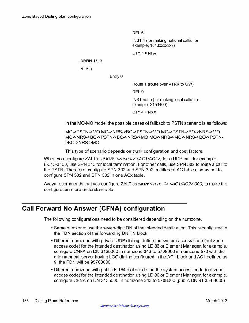
DEL 6
INST 1 (for making national calls: forexample, 1613xxxxxxx)
CTYP = NPA
ARRN 1713
RLS 5
Entry 0
Route 1 (route over VTRK to GW)
DEL 9
INST none (for making local calls: forexample, 2453400)
CTYP = NXX
In the MO-MO model the possible cases of fallback to PSTN scenario is as follows:
MO->PSTN->MO MO->NRS->BO->PSTN->MO MO->PSTN->BO->NRS->MOMO->NRS->BO->PSTN->BO->NRS->MO MO->NRS->MO->NRS->BO->PSTN->BO->NRS->MO
This type of scenario depends on trunk configuration and cost factors.When you configure ZALT as ZALT <zone #> <AC1/AC2>, for a UDP call, for example,6-343-3100, use SPN 343 for local termination. For other calls, use SPN 302 to route a call tothe PSTN. Therefore, configure SPN 302 and SPN 302 in different AC tables, so as not toconfigure SPN 302 and SPN 302 in one ACx table.
Avaya recommends that you configure ZALT as ZALT <zone #> <AC1/AC2> 000, to make theconfiguration more understandable.
Call Forward No Answer (CFNA) configurationThe following configurations need to be considered depending on the numzone.
• Same numzone: use the seven-digit DN of the intended destination. This is configured inthe FDN section of the forwarding DN TN block.
• Different numzone with private UDP dialing: define the system access code (not zoneaccess code) for the intended destination using LD 86 or Element Manager, for example,configure CNFA on DN 3435000 in numzone 343 to 5708000 in numzone 570 with theoriginator call server having LOC dialing configured in the AC1 block and AC1 defined as9, the FDN will be 95708000.
• Different numzone with public E.164 dialing: define the system access code (not zoneaccess code) for the intended destination using LD 86 or Element Manager, for example,configure CFNA on DN 3435000 in numzone 343 to 5708000 (public DN 91 354 8000)
Zone Based Dialing plan configuration
186 Dialing Plans Reference March 2013Comments? [email protected]
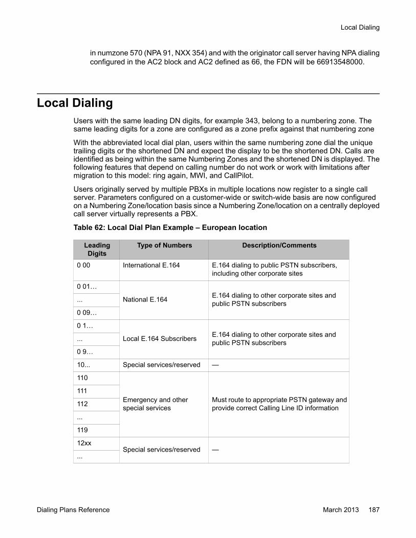
in numzone 570 (NPA 91, NXX 354) and with the originator call server having NPA dialingconfigured in the AC2 block and AC2 defined as 66, the FDN will be 66913548000.
Local DialingUsers with the same leading DN digits, for example 343, belong to a numbering zone. Thesame leading digits for a zone are configured as a zone prefix against that numbering zone
With the abbreviated local dial plan, users within the same numbering zone dial the uniquetrailing digits or the shortened DN and expect the display to be the shortened DN. Calls areidentified as being within the same Numbering Zones and the shortened DN is displayed. Thefollowing features that depend on calling number do not work or work with limitations aftermigration to this model: ring again, MWI, and CallPilot.
Users originally served by multiple PBXs in multiple locations now register to a single callserver. Parameters configured on a customer-wide or switch-wide basis are now configuredon a Numbering Zone/location basis since a Numbering Zone/location on a centrally deployedcall server virtually represents a PBX.
Table 62: Local Dial Plan Example – European location
LeadingDigits
Type of Numbers Description/Comments
0 00 International E.164 E.164 dialing to public PSTN subscribers,including other corporate sites
0 01…
National E.164 E.164 dialing to other corporate sites andpublic PSTN subscribers...
0 09…
0 1…
Local E.164 Subscribers E.164 dialing to other corporate sites andpublic PSTN subscribers...
0 9…
10... Special services/reserved —
110
Emergency and otherspecial services
Must route to appropriate PSTN gateway andprovide correct Calling Line ID information
111
112
...
119
12xxSpecial services/reserved —
...
Local Dialing
Dialing Plans Reference March 2013 187

LeadingDigits
Type of Numbers Description/Comments
19xx
2xxx
Local extensionsPhones and local services such as fax, voicemail, etc. Normally the last digits of E.164 DIDnumber.
...
8xxx
9 Attendant/Operatorservices —
Table 63: Local Dial Plan Example — North American location
LeadingDigits
Type of Numbers Description/Comments
0 Attendant/Operatorservices
—
10...
Special services/reserved —...
19
2xxx Local extensionsPhones and local services such as fax, voicemail, etc. Normally the last E.164 DID digits ofnumbers.
...
8xxx
9011 International E.164 E.164 dialing to public PSTN subscribers,including other corporate sites
902...Collect calling of NationalE.164 —...
909...
910... Equal access to carriers E.164 dialing to other corporate sites andpublic PSTN subscribers
911 Emergency services —
912...
National E.164 North American Dialing in the form:1-NPA-NXX-XXXX...
919...
92... Local Subscriber E.164Local Dialing in the forms:NPA-NXX-XXXXNXX-XXXX (where allowed)
...
98...
9911 Emergency services —
Zone Based Dialing plan configuration
188 Dialing Plans Reference March 2013Comments? [email protected]
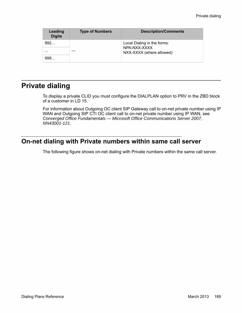
LeadingDigits
Type of Numbers Description/Comments
992...
—
Local Dialing in the forms:NPA-NXX-XXXXNXX-XXXX (where allowed)...
999...
Private dialingTo display a private CLID you must configure the DIALPLAN option to PRV in the ZBD blockof a customer in LD 15.
For information about Outgoing OC client SIP Gateway call to on-net private number using IPWAN and Outgoing SIP CTI OC client call to on-net private number using IP WAN, seeConverged Office Fundamentals — Microsoft Office Communications Server 2007,NN43001-121.
On-net dialing with Private numbers within same call serverThe following figure shows on-net dialing with Private numbers within the same call server.
Private dialing
Dialing Plans Reference March 2013 189

Figure 30: On-Net Dialing with Private Numbers within same Call Server
Table 64: Numbering zone configuration (LD 117) for on-net dialing within same CallServer
Zone PREF CC NPA AC1 AC2 NATC INTC DAC TTBL FLAGS1 301 9 6
2 302 0 6
Table 65: ZFDP table configuration for on-net dialing within same Call Server
Numzone Matchingdigits
Type Replacementdigits
Max length Description
1 6 LOC 6
2 6 LOC 6
Sets (LD 110)
Site 301:
NUMZONE 1
...
Zone Based Dialing plan configuration
190 Dialing Plans Reference March 2013Comments? [email protected]
KEY 00 SCR 3014100
...
Site 302:
NUMZONE 2
..
KEY 00 SCR 3023100
...
1. The user at site 301 dials 6 302 3100 to reach a user with DN 3023100 at site302.
2. Digit Manipulation and Routing: 6 302 3100 is pre-translated to 3016 302 3100.
The ZFDP entry handles the pretranslation for numbering zone 1, which removessite prefix, translates digits according to call type defined, and adds systemAC1/AC2 access prefix. This changes the number to 90 302 3100, (90 is the systemAC1/AC2 in this example).
After handling the pretranslation with the AC1 table, using SPN 302 and configuredas follows:
SPN 302
LTER YES – local termination
The number does not change because the same DN already exists in the system.
3. The Call Server determines the availability of adequate bandwidth and alerts theappropriate stations. The software determines whether a call between thenumbering zone processes. The software then checks DIALPLAN and displays asa PRV 7-digit DN.
On-Net Dialing with Private Numbers across different Call ServersThe following example shows the configuration for on-net dialing across different call serversfor call server 1 for numbering zone LD 117.
Table 66: Numbering zone configuration for on-net dialing across different Call Servers(CS1)
Zone PREF CC NPA ACI AC2 NATC INTC DAC TTBL FLAGS1 301 9 6
Private dialing
Dialing Plans Reference March 2013 191

Table 67: ZFDP table configuration for on-net dialing across different Call Servers (CS1)
Numzone Matchingdigits
Type Replacementdigits
Maxlength
Description
1 6 LOC 8
Sets (LD 11):
Site 301:
NUMZONE 1
...
KEY 00 SCR 3014100
...
The following example shows the configuration for on-net dialing across different call serversfor call server 2 for numbering zone LD 117.
Table 68: Numbering zone configuration for on-net dialing across different Call Servers(CS1)
Zone PREF CC NPA ACI AC2 NATC INTC DAC TTBL FLAGS1 502 9
Table 69: ZFDP table configuration for on-net dialing across different Call Servers (CS2)
Numzone Matchingdigits
Type Replacementdigits
Maxlength
Description
1 9 LOC 8
Sets (LD 11)
Site 502:
NUMZONE 1
...
KEY 00 SCR 5023100
...
1. The user at site 301 dials 6 502 3100 to reach a user with external DN 5023100 atsite 502.
2. Digit Manipulation and Routing 6 502 3100 is pre-translated to 3016 502 3100.
Zone Based Dialing plan configuration
192 Dialing Plans Reference March 2013Comments? [email protected]

The ZFDP entry handles the pretranslation for numbering zone 1 in Call Server 1,which removes site prefix and adds system AC1/AC2 access prefix. This changesthe number to 90 502 3100, (90 is the system AC1/AC2 in this example).
After handling the pretranslation with the AC1 table, using SPN 302, it is configuredas follows:
SPN 502
RLI Virtual trunk route
3. The Call Server sends the call over the virtual trunk to another call server. NRSdefines the call server with starting number 502. A 502 entry in the AC1/AC2/CDPtable handles the call. CLID remains seven-digits due to DIALPLAN PRV. When thecall arrives at Call Server 2, the incoming CLID is displayed on the phone at site502.
Figure 31: On-Net Dialing with Private Numbers across different Call Servers
Private dialing
Dialing Plans Reference March 2013 193
Outgoing OC client SIP Gateway call to on-net Private number usingIP WAN
Within an outgoing OC client SIP Gateway call to on-net Private number using IP WAN scenariothe following occurs in order:
1. The OC client-user dials a private number.
2. The Multimedia Convergence Manager (MCM) queries the Active Directory for thephone number, the Call Number, for the OC client-user.
3. The Active Directory responds with the matching number.
4. The MCM sends the Call Number to the Avaya Redirect Server (NRS).
5. The NRS responds with the matching Communication Server 1000 associated withthe Caller.
6. The call is sent to Communication Server 1000 used by the Caller.
7. The ZONE Prefix is inserted, based on numbering zone configuration, for all dialeddigits from the OC SIP Gateway and Services. Introduction of the Prefix (PREF)avoids the necessity for the Pretranslation table configuration.
8. The Call Server determines the availability of adequate bandwidth and alerts theappropriate stations. Calling Line Identification (CLID) is changed from a seven digitto a 3-5 digit local DN and Name Display for Intranumzone calls; for Internumzonecalls CLID is seven-digits.
See Figure 32: Outgoing OC client SIP Gateway call to On-Net Private number using IPWAN on page 195 for a diagram of the Outgoing OC client SIP Gateway call to On-Net Privatenumber using IP WAN.
Zone Based Dialing plan configuration
194 Dialing Plans Reference March 2013Comments? [email protected]

Figure 32: Outgoing OC client SIP Gateway call to On-Net Private number using IP WAN
Call Flow for Local DialingUsers dialing within a site or zone (3 to 4 digit dialing) to and from a digital or analog phone orattendant on the SMG or SBO with the same leading DN digits, for example 301, belong toone numbering Zone. Configure the same leading digits for a Zone as a Zone Prefix againstthat numbering zone.
The following table shows the call flow for Local Dialing within a site or zone to and from aphone or attendant on Survivable Media Gateway (SMG) or SBO.
Table 70: Numbering zone configuration for local dialing within site to and from a digitalor analog phone or attendant on SMG or SBO
Zone PREF CC NPA AC1 AC2 NATC INTC DAC TTBL FLAGS1 301
Sets: (LD 11)
Set 1
Call Flow for Local Dialing
Dialing Plans Reference March 2013 195
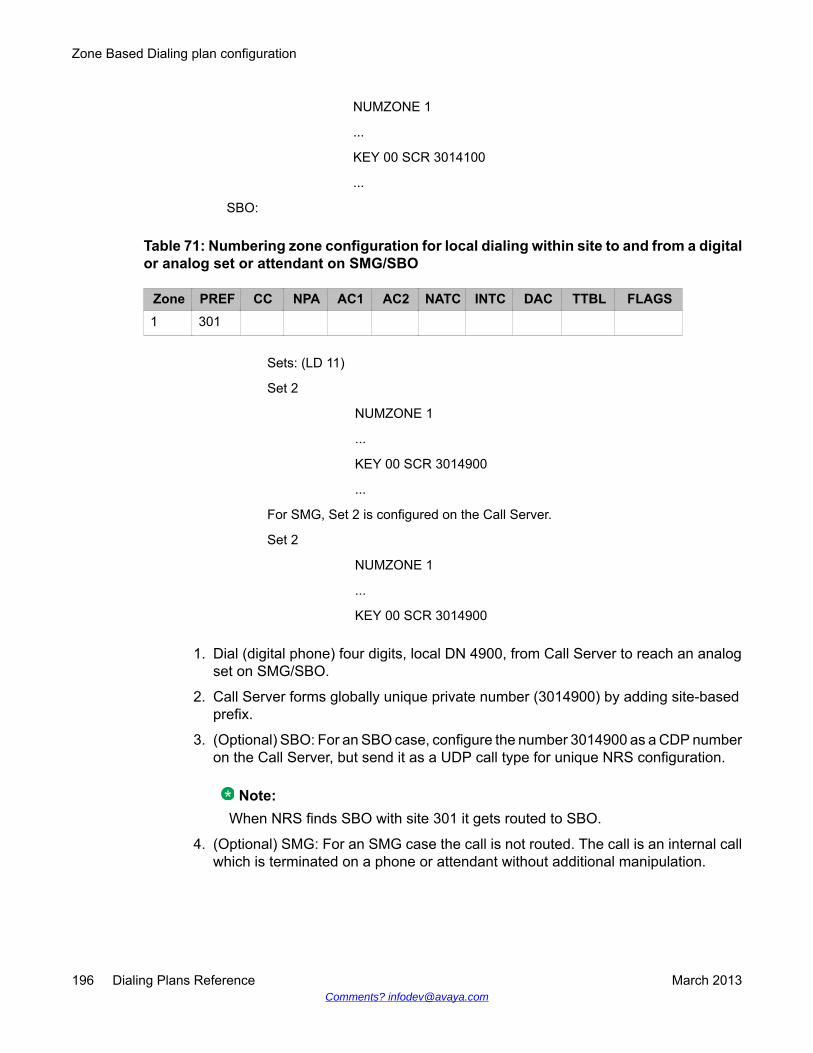
NUMZONE 1
...
KEY 00 SCR 3014100
...
SBO:
Table 71: Numbering zone configuration for local dialing within site to and from a digitalor analog set or attendant on SMG/SBO
Zone PREF CC NPA AC1 AC2 NATC INTC DAC TTBL FLAGS1 301
Sets: (LD 11)
Set 2
NUMZONE 1
...
KEY 00 SCR 3014900
...
For SMG, Set 2 is configured on the Call Server.
Set 2
NUMZONE 1
...
KEY 00 SCR 3014900
1. Dial (digital phone) four digits, local DN 4900, from Call Server to reach an analogset on SMG/SBO.
2. Call Server forms globally unique private number (3014900) by adding site-basedprefix.
3. (Optional) SBO: For an SBO case, configure the number 3014900 as a CDP numberon the Call Server, but send it as a UDP call type for unique NRS configuration.
Note:When NRS finds SBO with site 301 it gets routed to SBO.
4. (Optional) SMG: For an SMG case the call is not routed. The call is an internal callwhich is terminated on a phone or attendant without additional manipulation.
Zone Based Dialing plan configuration
196 Dialing Plans Reference March 2013Comments? [email protected]

Figure 33: Private Dial plan: Call Flow for Local Dialing within a site or zone (3-4 digit dialing) toand from a digital or analog phone or attendant on SMG or SBO
Call Flow for Local Dialing
Dialing Plans Reference March 2013 197
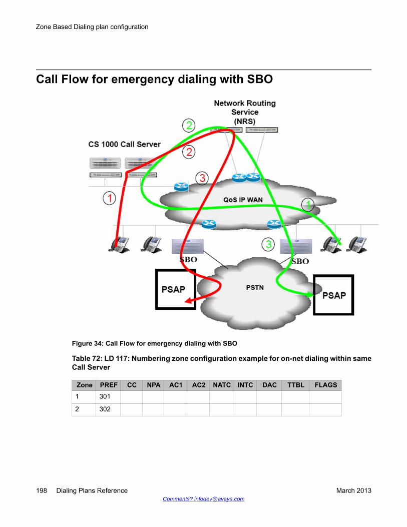
Call Flow for emergency dialing with SBO
Figure 34: Call Flow for emergency dialing with SBO
Table 72: LD 117: Numbering zone configuration example for on-net dialing within sameCall Server
Zone PREF CC NPA AC1 AC2 NATC INTC DAC TTBL FLAGS1 301
2 302
Zone Based Dialing plan configuration
198 Dialing Plans Reference March 2013Comments? [email protected]
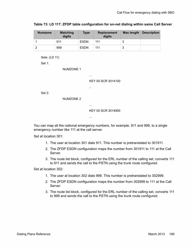
Table 73: LD 117: ZFDP table configuration for on-net dialing within same Call Server
Numzone Matchingdigits
Type Replacementdigits
Max length Description
1 911 ESDN 111 3
2 999 ESDN 111 3
Sets: (LD 11)
Set 1:
NUMZONE 1
...
KEY 00 SCR 3014100
..
Set 2:
NUMZONE 2
...
KEY 00 SCR 3014900
...
You can map all the national emergency numbers, for example, 911 and 999, to a singleemergency number like 111 at the call server.
Set at location 301:
1. The user at location 301 dials 911. This number is pretranslated to 301911.
2. The ZFDP ESDN configuration maps the number from 301911 to 111 at the CallServer.
3. The route list block, configured for the ERL number of the calling set, converts 111to 911 and sends the call to the PSTN using the trunk route configured.
Set at location 302:
1. The user at location 302 dials 999. This number is pretranslated to 302999.
2. The ZFDP ESDN configuration maps the number from 302999 to 111 at the CallServer.
3. The route list block, configured for the ERL number of the calling set, converts 111to 999 and sends the call to the PSTN using the trunk route configured.
Call Flow for emergency dialing with SBO
Dialing Plans Reference March 2013 199
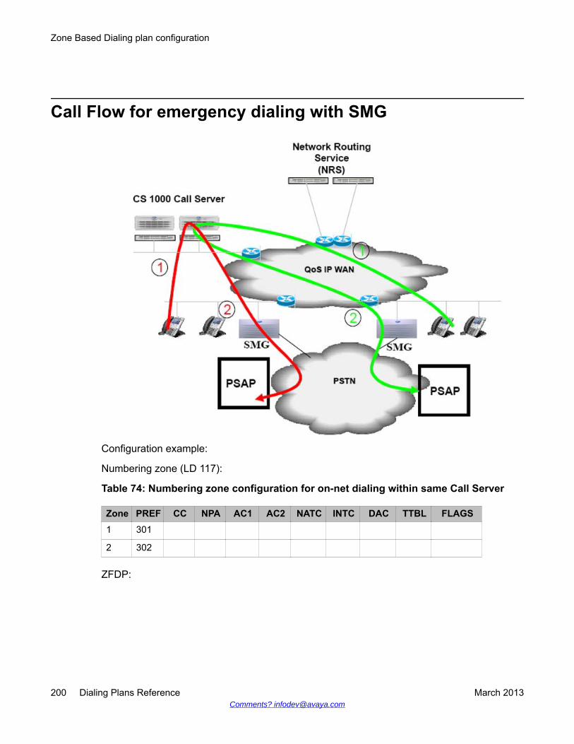
Call Flow for emergency dialing with SMG
Configuration example:
Numbering zone (LD 117):
Table 74: Numbering zone configuration for on-net dialing within same Call Server
Zone PREF CC NPA AC1 AC2 NATC INTC DAC TTBL FLAGS1 301
2 302
ZFDP:
Zone Based Dialing plan configuration
200 Dialing Plans Reference March 2013Comments? [email protected]
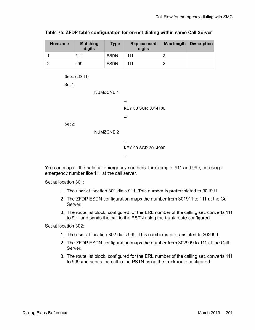
Table 75: ZFDP table configuration for on-net dialing within same Call Server
Numzone Matchingdigits
Type Replacementdigits
Max length Description
1 911 ESDN 111 3
2 999 ESDN 111 3
Sets: (LD 11)
Set 1:
NUMZONE 1
...
KEY 00 SCR 3014100
...
Set 2:
NUMZONE 2
...
KEY 00 SCR 3014900
...
You can map all the national emergency numbers, for example, 911 and 999, to a singleemergency number like 111 at the call server.
Set at location 301:
1. The user at location 301 dials 911. This number is pretranslated to 301911.
2. The ZFDP ESDN configuration maps the number from 301911 to 111 at the CallServer.
3. The route list block, configured for the ERL number of the calling set, converts 111to 911 and sends the call to the PSTN using the trunk route configured.
Set at location 302:
1. The user at location 302 dials 999. This number is pretranslated to 302999.
2. The ZFDP ESDN configuration maps the number from 302999 to 111 at the CallServer.
3. The route list block, configured for the ERL number of the calling set, converts 111to 999 and sends the call to the PSTN using the trunk route configured.
Call Flow for emergency dialing with SMG
Dialing Plans Reference March 2013 201

Initial DN key download for Local DN (3-5 digits)
Figure 35: Initial DN Key Download
Configuration Example: Call Server: Numbering zone (LD 117)
Table 76: Numbering zone configuration for emergency dialing with SMG
Zone PREF CC NPA AC1 AC2 NATC INTC DAC TTBL FLAGS1 301
2 302
Sets: (LD 11)
Set 1
NUMZONE 1
...
KEY 00 SCR 3015555
...
Set 2
Zone Based Dialing plan configuration
202 Dialing Plans Reference March 2013Comments? [email protected]
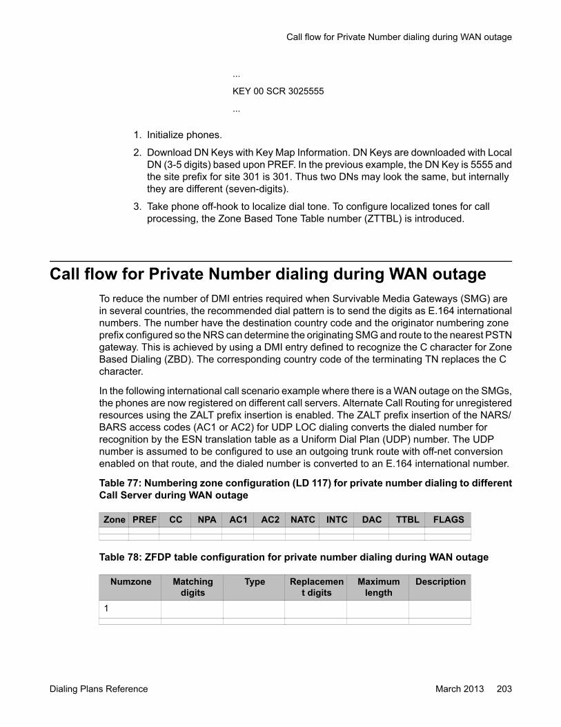
...
KEY 00 SCR 3025555
...
1. Initialize phones.
2. Download DN Keys with Key Map Information. DN Keys are downloaded with LocalDN (3-5 digits) based upon PREF. In the previous example, the DN Key is 5555 andthe site prefix for site 301 is 301. Thus two DNs may look the same, but internallythey are different (seven-digits).
3. Take phone off-hook to localize dial tone. To configure localized tones for callprocessing, the Zone Based Tone Table number (ZTTBL) is introduced.
Call flow for Private Number dialing during WAN outageTo reduce the number of DMI entries required when Survivable Media Gateways (SMG) arein several countries, the recommended dial pattern is to send the digits as E.164 internationalnumbers. The number have the destination country code and the originator numbering zoneprefix configured so the NRS can determine the originating SMG and route to the nearest PSTNgateway. This is achieved by using a DMI entry defined to recognize the C character for ZoneBased Dialing (ZBD). The corresponding country code of the terminating TN replaces the Ccharacter.
In the following international call scenario example where there is a WAN outage on the SMGs,the phones are now registered on different call servers. Alternate Call Routing for unregisteredresources using the ZALT prefix insertion is enabled. The ZALT prefix insertion of the NARS/BARS access codes (AC1 or AC2) for UDP LOC dialing converts the dialed number forrecognition by the ESN translation table as a Uniform Dial Plan (UDP) number. The UDPnumber is assumed to be configured to use an outgoing trunk route with off-net conversionenabled on that route, and the dialed number is converted to an E.164 international number.
Table 77: Numbering zone configuration (LD 117) for private number dialing to differentCall Server during WAN outage
Zone PREF CC NPA AC1 AC2 NATC INTC DAC TTBL FLAGS
Table 78: ZFDP table configuration for private number dialing during WAN outage
Numzone Matchingdigits
Type Replacement digits
Maximumlength
Description
1
Call flow for Private Number dialing during WAN outage
Dialing Plans Reference March 2013 203

1. A user in Galway, Ireland dials a string that has been previously configured in theZFDP table for CDP dialing, for example, 6-111-2170.
A WAN outage for both SMGs occurs and the phones are now registered on differentcall servers so alternate routing using the ZALT prefix insertion is activated andinserts the system AC1 to trigger ESN processing.
2. The dialed number is recognized by the ESN translation as a UDP number and theUDP number is configured for routing on an outgoing trunk route with off-netconversion enabled on that route. The dialed number is converted to an E.164international number.
A digit manipulation entry is defined to recognize the C character and to replacethese characters in the dialed digit string with the corresponding country code ofthe terminating TN in place of the C character.
3. The number is converted to 00 91 0 594 628 2070 and is routed through the NRSto the alternate network.
Zone Based Dialing plan configuration
204 Dialing Plans Reference March 2013Comments? [email protected]
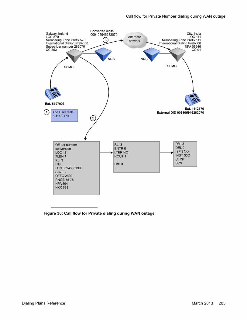
Figure 36: Call flow for Private dialing during WAN outage
Call flow for Private Number dialing during WAN outage
Dialing Plans Reference March 2013 205

Figure 37: Digit conversion
For more information about on-net to off-net conversion, see Basic Network FeatureFundamentals, NN43001-579.
LD TablesUse the following prompts for ZBD:
• Overlay 10, 11: NUMZONE prompt assigns a numbering zone to a phone (analog, TDM,IP).
• Overlay 12: NUMZONE prompt assigns a numbering zone to an attendant.• Overlay 15: ZBD prompt enables or disables the ZBD feature. The prompt DIALPLAN
shows DN/CLID for private/public on-net dial plans.
Difference between PUB and PRV dialplans
If DIALPLAN is configured to PUB, Phone A with DN (301)4100 dials E.164 number ofPhone B with DN (302)3100, 9011 31 20 630 3100, CLID on Phone B is 1 613 967 4100
When DIALPLAN is configured to PRV, Phone A with DN (301)4100 dials private numberof Phone B with DN (302)3100, 6 302 3100, CLID on Phone B is 301 4100
• Overlay 20: NUMZONE prompt displays a numbering zone configured for a set (analog,TDM, IP) or attendant.
Zone Based Dialing plan configuration
206 Dialing Plans Reference March 2013Comments? [email protected]
• Overlay 21: ZBD prompt displays the value of the ZBD option. The prompt DIALPLANshows the configured value in the customer data block
• Overlay 22: The ZBD package is printed.• Overlay 43: The ZBD databases are dumped into /u/db/ during EDD. These ZBD
databases are restored from /u/db/ during database restore.• Overlay 81: NZON prompt prints a list or count of telephones with a selected numbering
zone.• Overlay 83: NUMZONE prompt prints a list of units with a configured numbering zone.• Overlay 117: Configure numbering zones and parameters for numbering zone (prefix,
DAPC, CC, NPA, ACx …), Zone Based Dialing plan.The following tables provide ZBD implementation prompts and responses.
LD 15: Configure zone based parameters for ZBD optionUse the following to enable or disable the ZBD feature and to show the DN/CLID for private/public on-net dial plans.
Table 79: LD 15
Prompt Response DescriptionREQ: CHG NEW Change or create new
TYPE: FTR_DATA Customer Features and options data block
CUST xx Customer number as defined in LD 15
...
VO_CUR_ZONE_TD
(NO) YES
ZBD (NO) YES ZBD option
- DIAL PLAN PUB/PRV Type of dialing plan for DN/CLID displaying
LD 117: Configure numbering zone and numbering zone basedparameters
Use the following to configure numbering zone parameters.
LD Tables
Dialing Plans Reference March 2013 207
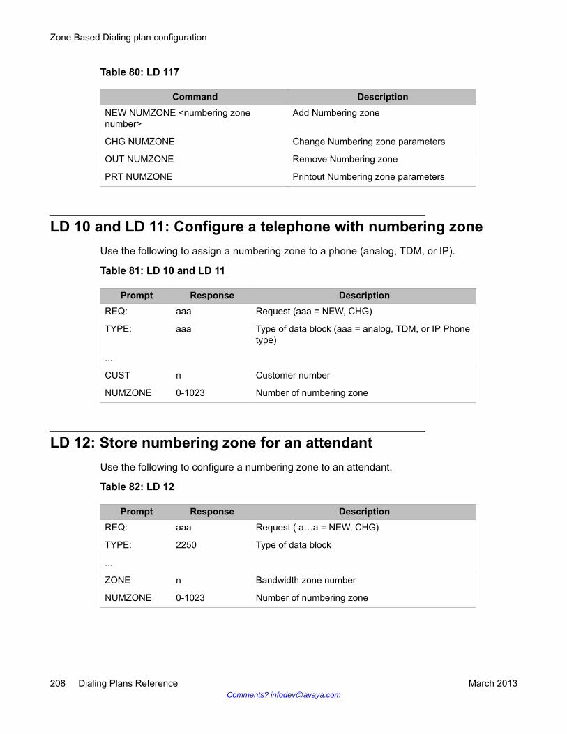
Table 80: LD 117
Command DescriptionNEW NUMZONE <numbering zonenumber>
Add Numbering zone
CHG NUMZONE Change Numbering zone parameters
OUT NUMZONE Remove Numbering zone
PRT NUMZONE Printout Numbering zone parameters
LD 10 and LD 11: Configure a telephone with numbering zoneUse the following to assign a numbering zone to a phone (analog, TDM, or IP).
Table 81: LD 10 and LD 11
Prompt Response DescriptionREQ: aaa Request (aaa = NEW, CHG)
TYPE: aaa Type of data block (aaa = analog, TDM, or IP Phonetype)
...
CUST n Customer number
NUMZONE 0-1023 Number of numbering zone
LD 12: Store numbering zone for an attendantUse the following to configure a numbering zone to an attendant.
Table 82: LD 12
Prompt Response DescriptionREQ: aaa Request ( a…a = NEW, CHG)
TYPE: 2250 Type of data block
...
ZONE n Bandwidth zone number
NUMZONE 0-1023 Number of numbering zone
Zone Based Dialing plan configuration
208 Dialing Plans Reference March 2013Comments? [email protected]

LD 81: Print a list or count of telephones with selected numberingzone
Use the following to print a list or count of telephones with a selected numbering zone.
Table 83: LD 81
Prompt Response DescriptionREQ: aaa Request (aaa = LST, CNT, or END)
CUST: Xx xx One Customer or a range of Customer numbers
...
FEAT n Bandwidth zone number
NZON 0-1023 Number of numbering zone
0-1023 0-1023 Range of Numbering Zones
<CR> All Numbering Zones
Diagnostic logsWhen MON 2 traces are enabled for the D-Channel in Overlay 96 of the Call Server, new ZBDINFO IE prints with its contents.
The debug facility is introduced in Communication Server as a part of the diagnostic log feature.The PDT shell executes commands. To turn on debug output, the following command is used:pdt> dfo 2 1.
When Zone Based dialing is active, diagnostic information and messages are displayed forcall processing in each step of modifying DN and CLID.
To turn off diagnostic messages, use the following command: pdt> dfo 2 0.
To check the status of debug output, use the following command: pdt> dfo 2 2.
To print help for debug commands, use dfo 0.
Working from the debug shell, the following additional debug information displays for the ZFDPfeature:
dbg > ZBDDebugLevelSet <level>
Where <level> is the monitoring level; the value can be from 0 to 3; 0 is used to turn off thediagnostic printout.
Diagnostic logs
Dialing Plans Reference March 2013 209

The following print-out is an example of DFO logs for the Zone Based Dialing plan. Thediagnostic log is printed on tty when DFO is enabled for Zone Based Dialing:
INFO211 ZBD: 1 00000008 00000000 00000000 00000000 00000128 1 INFO212ZBD: 1 00000003 00000000 00000000 00000000 00000001 INFO211 ZBD: 800006000 00000000 00000000 00000000 00000000 7 INFO212 ZBD: 80000000C 00000007 00000000 00000000 00000001 INFO211 ZBD: 8 0000600000000000 00000000 00000000 00000000 1 INFO212 ZBD: 8 0000000C00000001 00000000 00000000 00000001 INFO211 ZBD: 8 00006000 0000000000000000 00000000 00000000 INFO212 ZBD: 8 0000000C 00000000 0000000000000000 00000001 INFO205 ZBD: 3116119 0023F1C6 0F044408 00000001INFO211 ZBD: 7 00000000 00000000 00000000 00000000 00000000 3116119INFO212 ZBD: 7 00006185 00000000 08FFBA4A 00000000 00000001 INFO206ZBD: 3116119 00006000 00006185 00000000 INFO211 ZBD: 8 0000618500000000 00000000 00000000 00000000 7 INFO212 ZBD: 8 0000000C00000007 00000000 00000000 00000001 INFO211 ZBD: 8 00006000 0000000000000000 00000000 00000000 7 INFO212 ZBD: 8 0000000C 0000000700000000 00000000 00000001 INFO207 ZBD: 0000000C 0000000C 00000000
Zone Based Dialing plan configuration
210 Dialing Plans Reference March 2013Comments? [email protected]
Index
Special Characters
_ADFT prompt .......................................................... 107_DGTO prompt ......................................................... 107_ENBS prompt ..........................................................107_IFTO prompt ........................................................... 107_IIT prompt ............................................................... 107_INIT prompt .............................................................107_MONT prompt .........................................................107_TIMER prompt ........................................................ 107_TIMR prompt ...........................................................107
Numerics
10X calls .....................................................................9610XXX designator ...................................................... 693ANI prompt ............................................................. 10795Y-calls .....................................................................96
A
AC1 access code ....................................................... 92AC1/2 ......................................................................... 61AC2 access code ....................................................... 92access restrictions ......................................................81acknowledgment winks .........................................72, 76addresses ........................................................72, 75, 92
EANA ................................................................... 72field ...................................................................... 75format validation ...................................................92
ADFT prompt ............................................................ 107administration ............................................................. 60
Vacant Number Routing .......................................60AMA (Automatic Message Accounting) ................ 71, 72ANI (Automatic Number Identification) ....66, 70, 72, 76,
92, 98, 100as CLID .............................................................. 100displaying ........................................................... 100field format validation ...........................................92in EANA ..........................................................72, 76screening ........................................................92, 98with IEC ................................................................70
ANII prompt .............................................................. 107ANIT prompt ............................................................. 107answer time limits .......................................................76ARRN (Alternate Routing Remote Number) ... 39, 53, 63
maximum digits for SPNs .....................................63off-network dialing .......................................... 39, 53
ARRN SDRR .............................................................. 39ATM (Automatic Trunk Maintenance) ......................... 66Authorization Code prompting ....................................97
B
Barge-In ......................................................................85BARS (Basic Alternate Route Selection) 39, 53, 66, 92, 96
off-network dialing .......................................... 39, 53BARS translator ..........................................................62BAUT (Basic Authorization Code) .............................. 66blocks, maximum ......................................................102BRTE (Basic Routing) ................................................ 66BSWT (Bell Operating Company Switch Time) ..........76
C
CAB (Charge Account) ...............................................66CAC (Carrier Access Codes) ..................................... 65Call Park modifications ...............................................86Call Park Recall modifications ....................................86called customers ........................................................ 67calling customers ........................................................67calls ....................................... 68, 73, 91, 95, 96, 101, 107
categories ............................................................ 73domestic ...............................................................68for testing ................................................ 95, 96, 101initiating ................................................................91intercepts ............................................................. 96registers ............................................................. 107
capacity expansion .....................................................61carriers ..................................................................71, 73
classification .........................................................73test lines ...............................................................71
CBQ prompt ..............................................................113CCAN prompt ........................................................... 107CCLS prompt ............................................................107CCR (Customer Controlled Routing) ..........................85CDAN prompt ........................................................... 107CDEN prompt ........................................................... 107CDP (Coordinated Dialing Plan) .............. 38, 42, 51, 119
configuring ..........................................................119ISDN digit display .................................................51on-network dialing .......................................... 38, 42
CDR (Call Detail Recording) ............................... 85, 101
Dialing Plans Reference March 2013 211

CDRE (Call Detail Recording Expansion) .................. 66CIC prompt ............................................................... 107CLID (Calling Line Identification) ......63, 66, 85, 100, 121
defining ................................................................ 63LD 87 program ................................................... 121
CLS prompt .............................................................. 107CNTL prompt ............................................................ 107CNV prompt .............................................................. 113Conference/TDS .........................................................78conferences and DNIS ............................................... 86configurations ............................................................. 66connect signals ...........................................................71Consolidated Carrier .................................................. 73CPAR prompt ............................................................107CPDC (Call Party Disconnect Control) .......................85CPND (Call Party Name Display) ...............................85CSWT (Carrier Switch Time) ......................................76CUST prompt ............................................................107
D
DASS2 (Digital Access Signaling System 2) ..............62DDD (Direct Distant Dialing) ................................. 39, 53
alternative routing ................................................ 53off-network dialing ................................................39
DDSP (Digit Display) ............................................ 66, 86DHC (D-channel) ........................................................66dialing, pulse .............................................................101DID (Direct Inward Dialing) numbers .................... 39, 53
alternative routing ................................................ 53off-network dialing ................................................39
digitone receiver and tone detector prompts ............ 107digittone receiver and tone detector prompts ........... 107DISR command ................................................. 115, 116DMI (Digit Manipulation Index) tables ........................ 61
expansion of .........................................................61DMI prompt ............................................................... 113DN (Directory Number) ........................ 38, 42, 50, 62, 63
on-network dialing ................................................38prefix display ........................................................50translation entries .................................................62varying lengths of ........................................... 42, 63
DN translation tables .................................................. 94DNIS (Dialed Number Identification Service) ......86, 102domestic calls .............................................................68DP (Dial Pulse) outpulsing ........................................101DPNSS1 (Digital Private Network Signaling System 1) 62DSC (Distant Steering Code) prompt ................... 50, 61
capacity expansion .............................................. 61ISDN digit display .................................................50
DTMF (Dual Tone Multifrequency) ............................102
E
EA (Equal Access) ..................................................... 65EANA (Exchange Access North American) protocol ....
72, 73, 75, 77, 94ANI in ................................................................... 72example ............................................................... 77for operator calls .................................................. 94pulsing formats for ............................................... 73specifications ....................................................... 75
embodied SAC calls ................................................... 97end office switching .................................................... 67end-of-dial timing ....................................... 42, 44, 57, 59
Coordinated Dialing Plan ..................................... 44FLEN processing of LOC dialing ..........................42NPA and NXX codes ............................................59SPNs ....................................................................57
engineering guidelines ..............................................107ENLR command ................................................ 115, 116ENTER YES TO CONFIRM prompt ......................... 107ENTR prompt ............................................................113error rates, MFR ......................................................... 79ESN (Electronic Switched Network) ......................... 113ESN (Electronic Switched Network) dialing plan .. 39, 62,
120, 121administration overlay .................................120, 121feature interactions .............................................. 62off-network dialing ................................................39
EX prompt .................................................................113expanding capacity .....................................................61external SAC calls ...................................................... 97
F
FCAS (Free Calling Area Screening) ......................... 60described ............................................................. 60
FCI prompt ................................................................113FEAT prompt .............................................................113feature interactions ............................................... 62, 81FGNO prompt ........................................................... 107FLEN (Flexible Length) prompt 41, 42, 53, 59, 62, 121, 124
dialing LOCs on-net ............................................. 41ESN feature interactions ......................................62LD 87 program ................................................... 121LD 90 program ................................................... 124NPA and NXX codes ............................................59SPN dialing .......................................................... 53termination attempts .......................................42, 53
frequency discrimination, MFR ...................................79FRL prompt ...............................................................113FSNS (Free Special Number Screening) ................... 60
212 Dialing Plans Reference March 2013

described ............................................................. 60
G
GDP (Group Dialing Plan) ...............................49, 51, 62described ............................................................. 49ISDN digit display .................................................51maximum number of digits ...................................62
H
hardware .................................................................... 78holding times for MFR .............................................. 102
I
IC (Incoming Calls) .................................... 69, 93, 95, 96II screening .......................................................... 95inside World Zone 1 ............................................. 93test ....................................................................... 96
IDC (Incoming Digit Conversion) ................................86identification fields, EANA .....................................72, 75IEC (Inter-Exchange Carrier) .....................65, 69, 70, 73
ANI with ................................................................70SAC with .............................................................. 69
II (Information digits) .......................... 75, 92, 95, 96, 107default values .....................................................107screening ........................................................92, 95test call .................................................................96with EANA ............................................................75
IIT prompt ................................................................. 107IITP prompt ...............................................................107implementation ......................................................... 102INC (International Carrier) .......................................... 73initiating calls .............................................................. 91input frequencies, MFR .............................................. 79input levels, MFR ........................................................79inter-digit pulses, MFR ............................................... 79intercepts ....................................................................96interface protocol .................................................. 71, 73INTR prompt ............................................................. 107invalid calls ................................................................. 96ISDN (Integrated Services Digital Network) .... 50, 62, 86
digit display .......................................................... 50feature interactions .............................................. 62FNP feature support .............................................62
ISDN Signaling ........................................................... 66ISL (ISDN Signaling Link) ..................................... 66, 86ITOH (Inhibit Time Out Handler) ....................... 121, 124
LD 87 program ................................................... 121LD 90 program ................................................... 124
L
LAAC (Local Area Access Code) ..........................92, 96LAAC prompt ............................................................ 107LATA (Local Access and Transport Area) .................. 67LD 13 program prompts ............................................107LD 14 program prompts ............................................107LD 16 program prompts ............................................107LD 20 program prompts ............................................113LD 21 program prompts ............................................113LD 22 program prompts ............................................113LD 29 program prompts ............................................113LD 30 program ..........................................................117LD 32 program ..........................................................117LD 34 program ..........................................................115LD 86 program prompts ............................................113LD 87 program ..........................................................119
NCTL data block configuration ...........................119LDAC (Long Distance Access Code) ......................... 92LDAC prompt ............................................................107LEC (Local Exchange Carrier) ..............................65, 67LEC-to-carrier pulsing ................................................ 75line tests ..................................................................... 71load capacity, MFR ................................................... 102LOC (Location Code) ........................... 38, 41, 49, 51, 61
capacity expansion .............................................. 61described ............................................................. 41Group Dialing Plan ...............................................49ISDN digit display .................................................51length in digits ......................................................38
local network switching ...............................................67local termination ......................................................... 93LSC (Local Steering Code) capacity expansion .........61LTER (Local Termination) entry ...........................93, 113LTER prompt .............................................................113
M
MCT (Malicious Call Trace) ........................................87memory management prompts .................................113MF loops .....................................................................78MF signaling ............................................................... 78MFR (Multi-Frequency Receiver) .................79, 102, 115
guidelines ...........................................................102load capacity ...................................................... 102maintenance and diagnostics .............................115maximum number of .......................................... 102requirements ...................................................... 102specifications ....................................................... 79
MFR command .................................................. 115, 116
Dialing Plans Reference March 2013 213
MFRC (MF Receiving Cards) ............................... 78, 79MFS (Multi-Frequency Senders) ................................ 78Minor Alarms .............................................................. 87MNDN prompt ...........................................................107
N
NANP (North American Numbering Plan) .............39, 69NARS (Network Alternate Route Selection) ... 39, 44, 53,
66, 87, 92, 93, 96end-of-dial timing ................................................. 44off-network dialing .......................................... 39, 53
NARS translator ......................................................... 62NAUT (Network Authorization Code) ......................... 66NCDP (number of Coordinated Dialing Plan digits) ... 38NCOS (Network Class of Service) .................. 66, 95, 97NCOS prompt ........................................................... 107NCRD (Network Call Redirection) .............................. 87NCTL (Network Control) block, configuring .............. 119network diagnostics .................................................. 117NIT (NARS interdigit timer) ................................. 59, 127
described ............................................................. 59modifying ............................................................127
node identification digits ............................................. 38noise immunity, MFR ..................................................79non-presubscribed users in initiating calls ..................91NPA (Number Plan Area) codes ................69, 76, 92, 98NPA (Numbering Plan Area) ......................39, 57, 59, 60
end-of-dial timing ................................................. 59Free Calling Area Screening ................................60off-network dialing .....................................39, 57, 59
NPA prompt .............................................................. 107Numbering Plan Area (NPA) and NXX ....................... 59NXX codes ...................................................... 57, 59, 60
end-of-dial timing ................................................. 59Free Calling Area Screening ................................60off-network dialing .......................................... 57, 59
NXX prompt .............................................................. 107
O
off-hook signals .....................................................71, 72off-network dialing ..................................... 39, 53, 57, 59
described ............................................................. 39end-of-dial timing ............................................57, 59NPA and NXX .................................................57, 59operation ..............................................................53software settings ..................................................57
OHQ prompt ............................................................. 113on-hook signals .....................................................71, 72on-network dialing .....................38, 41, 42, 44, 49, 50, 57
Coordinated Dialing Plan ..................................... 42described ............................................................. 38Group Dialing Plan ...............................................49ISDN digit display .................................................50operation ..............................................................41software settings ..................................................57Universal Numbering Plan ................................... 44
one-way trunks ........................................................... 71OPER prompt ........................................................... 107operating parameters ............................................... 102operators, calls to ....................................................... 94originating features .....................................................68outgoing test calls .....................................................101overlap pulsing ........................................................... 72OVF (Overflow Tone) ..................................................96OVLP prompt ............................................................107
P
pay-subscriptions, SAC for .........................................69PDS (Protected Data Store) ..................................... 102PE (Peripheral Equipment) ....................................... 117post-dialing delays ......................................................72POT (Point of Termination) ................................... 65, 71power lines, MFR ....................................................... 79PRES (Presubscriptions) ............................................69PRES prompt ............................................................107presubscribed users in initiating calls .........................91PRI (Primary Rate Interface) ................................ 66, 86print routine, prompts ................................................113Private Line Service ................................................... 87prompts ........................................................97, 107, 113
Authorization Code .............................................. 97digitone receiver and tone detector ....................107digittone receiver and tone detector ...................107ESN ....................................................................113memory management ........................................ 113print routine ........................................................ 113Route Data Blocks ............................................. 107Trunk Data Blocks ..............................................107
protocols ............................................................... 71, 73for call categories .................................................73interface ..........................................................71, 73
PRTD prompt ............................................................107pulse dialing ..............................................................101pulsing .................................................................. 72, 73
R
RAN (Recorded Announcement) ........................ 96, 107RDB (Route Data Block), configuring ....................... 119
214 Dialing Plans Reference March 2013

reception with disturbances, MFR .............................. 79Recorded Announcement Trunk routes ......................94REQ prompt ...................................................... 107, 113restrictions, access .....................................................81RLB (Route List Block) ......................................... 41, 61
expansion of .........................................................61LOC dialing .......................................................... 41
RLI (Route List Index) ...............................................124LD 90 program ................................................... 124
RLI prompt ................................................................ 113ROUT prompt .................................................... 107, 113Route Data Block prompts ........................................107Route List Entry ........................................................ 113routing calls ..................................................... 44, 53, 60
SDRR prompt .......................................................53software configuration for .....................................44
Universal Numbering Plan .............................44Vacant Number Routing .......................................60
RTMB prompt ........................................................... 107
S
SAC (Service Access Code) ...................................... 97SAC prompt .............................................................. 107SCH (Service Change) ....................................... 94, 107screening .........................................................92, 95, 98SDRR (Supplemental Digit Restriction or Recognition)
............................................................ 39, 53, 63feature interactions .............................................. 63off-network dialing .......................................... 39, 53
SDTR command ................................................ 115, 116Service Change programs ........................................ 115SHAN prompt ........................................................... 107SIGL prompt ............................................................. 107signals and signaling ...........................................79, 117
diagnostics ......................................................... 117duration, MFR ...................................................... 79interruptions, MFR ............................................... 79
SLV3 prompt .............................................................107SLV6 prompt .............................................................107software ................................................................ 44, 57
off-network dialing ................................................57on-network dialing ................................................57UNP TNDN configurations ...................................44
specifications, MFRC ................................................. 79SPN (Special Number) .........................39, 53, 57, 60, 63
end-of-dial timing ................................................. 57Free Special Number Screening ..........................60off-network dialing .......................................... 39, 53SDRR block size ..................................................63
STAT command ................................................. 115, 116STRI prompt ............................................................. 107
STRO prompt ........................................................... 107SUB prompt .............................................................. 107
T
TDET (Tone Detector) ................................................ 66TDET prompt ............................................................ 113TDS315 message ..................................................... 116terminating protocols ..................................... 73, 77, 102
example ............................................................... 77parameters .........................................................102pulsing formats for ............................................... 73
termination, call ............................................... 42, 53, 59NIT timer .............................................................. 59on-network dialing ................................................42SPN dialing .......................................................... 53
termination, local ........................................................ 93testing ............................................... 71, 95, 96, 101, 116
calls for ....................................................95, 96, 101lines for ................................................................ 71trunks ..................................................................116
TGAR prompt ........................................................... 107third frequency, MFR .................................................. 79time limits in EANA .....................................................76time shifts, MFR ......................................................... 79TKTP prompt ............................................................ 107TN prompt .................................................................107TNDN (Transferrable Directory Number) ........ 38, 44, 63
maximum digits ....................................................63on-network dialing ................................................38Universal Numbering Plan and ............................ 44
TOD (Time-of-Day) .....................................................93TOD prompt .............................................................. 113tolerance to twist, MFR ...............................................79toll-free numbers, SAC for ..........................................69tone and digital switch for maintenance ....................115traffic measurements .......................................... 88, 102Transfer modifications ................................................ 86transmission characteristics ..................................... 101Trunk Group Distinctive Ringing .................................88trunk seizure, SPN dialing and ................................... 53trunks ........................................................... 78, 107, 116
data block prompts for ........................................107testing .................................................................116
trunks, off-network dialing and ................................... 39TSC (Trunk Steering Code) .............................44, 59, 61
capacity expansion .............................................. 61end-of-dial timing ................................................. 44NIT timer .............................................................. 59
TVS (Trunk Verification from a Station) ......................88two-way trunks ........................................................... 71TWX service ............................................................... 69
Dialing Plans Reference March 2013 215
TYNM prompt ........................................................... 113TYPE prompt ............................................................ 107
U
UDP (Uniform Dialing Plan) ........................................38Universal Numbering Plan ..........................................44
TNDNs ................................................................. 44software configurations ................................. 44
UNP (Universal Numbering Plan) ...............................44transferrable DNs .................................................44
UNR (Unrestricted Access) ........................................ 81
V
VNR (Vacant Number Routing) ...........................60, 127
described ............................................................. 60enabling/disabling .............................................. 127
W
wink-start guard signals ..............................................76wink-start signals .............................................71, 72, 76WZ1 (World Zone 1) .................................. 68, 77, 93, 94
calls inside ........................................................... 93dialing example ....................................................77operator calls in ....................................................94
216 Dialing Plans Reference March 2013