Embed Size (px)
Citation preview
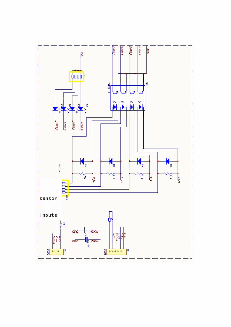
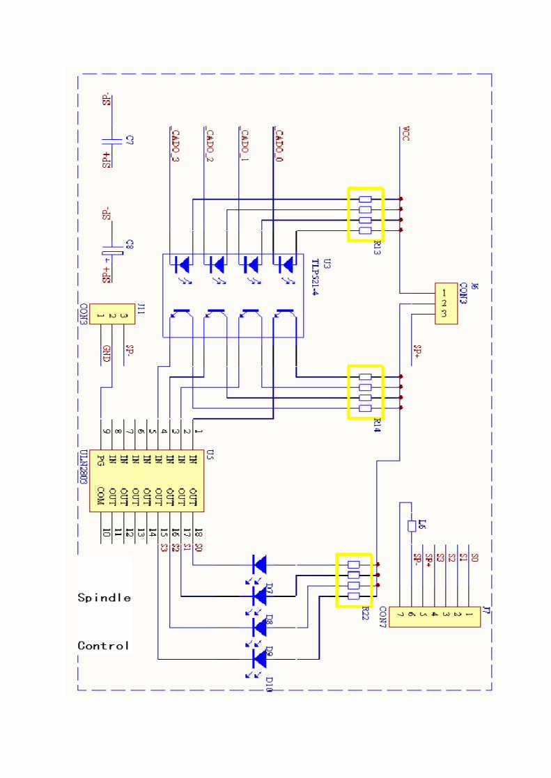
Diagram
RZNC-0501 Connection Board
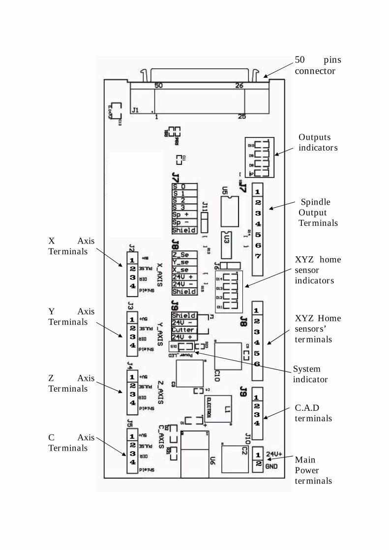
50 pinsconnector
Outputsindicators
SpindleOutputTerminals
XYZ Homesensors’terminals
C.A.Dterminals
MainPowerterminals
X AxisTerminals
Y AxisTerminals
Z AxisTerminals
C AxisTerminals
XYZ homesensorindicators
Systemindicator
1234
1234
1234
1234
1234
123456
1234567
12
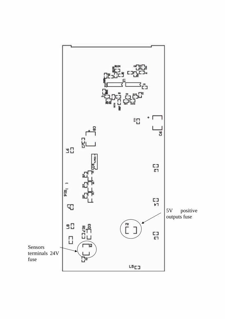
5V positiveoutputs fuse
Sensorsterminals 24Vfuse
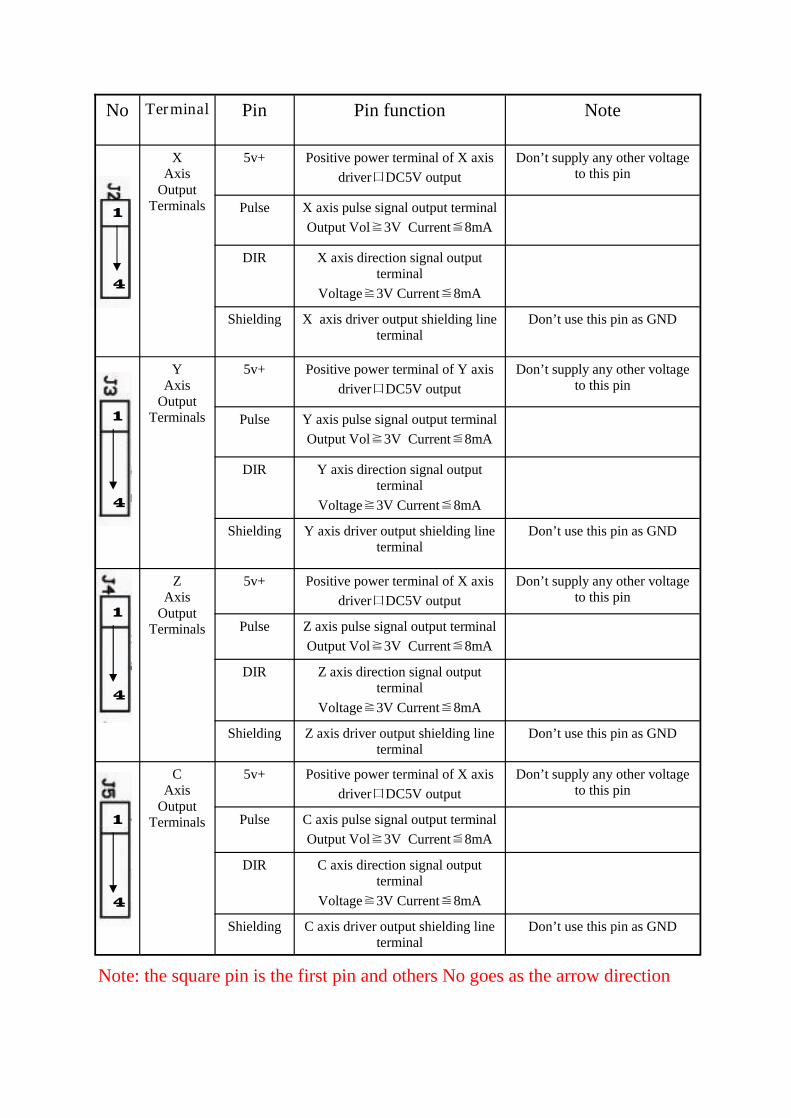
No Terminal Pin Pin function Note
XAxis
OutputTerminals
5v+ Positive power terminal of X axisdriver口DC5V output
Don’t supply any other voltageto this pin
Pulse X axis pulse signal output terminalOutput Vol≧3V Current≦8mA
DIR X axis direction signal outputterminal
Voltage≧3V Current≦8mA
Shielding X axis driver output shielding lineterminal
Don’t use this pin as GND
YAxis
OutputTerminals
5v+ Positive power terminal of Y axisdriver口DC5V output
Don’t supply any other voltageto this pin
Pulse Y axis pulse signal output terminalOutput Vol≧3V Current≦8mA
DIR Y axis direction signal outputterminal
Voltage≧3V Current≦8mA
Shielding Y axis driver output shielding lineterminal
Don’t use this pin as GND
ZAxis
OutputTerminals
5v+ Positive power terminal of X axisdriver口DC5V output
Don’t supply any other voltageto this pin
Pulse Z axis pulse signal output terminalOutput Vol≧3V Current≦8mA
DIR Z axis direction signal outputterminal
Voltage≧3V Current≦8mA
Shielding Z axis driver output shielding lineterminal
Don’t use this pin as GND
5v+ Positive power terminal of X axisdriver口DC5V output
Don’t supply any other voltageto this pin
Pulse C axis pulse signal output terminalOutput Vol≧3V Current≦8mA
DIR C axis direction signal outputterminal
Voltage≧3V Current≦8mA
Shielding C axis driver output shielding lineterminal
Don’t use this pin as GND
CAxis
OutputTerminals
1
4
1
4
1
4
1
4
Note: the square pin is the first pin and others No goes as the arrow direction
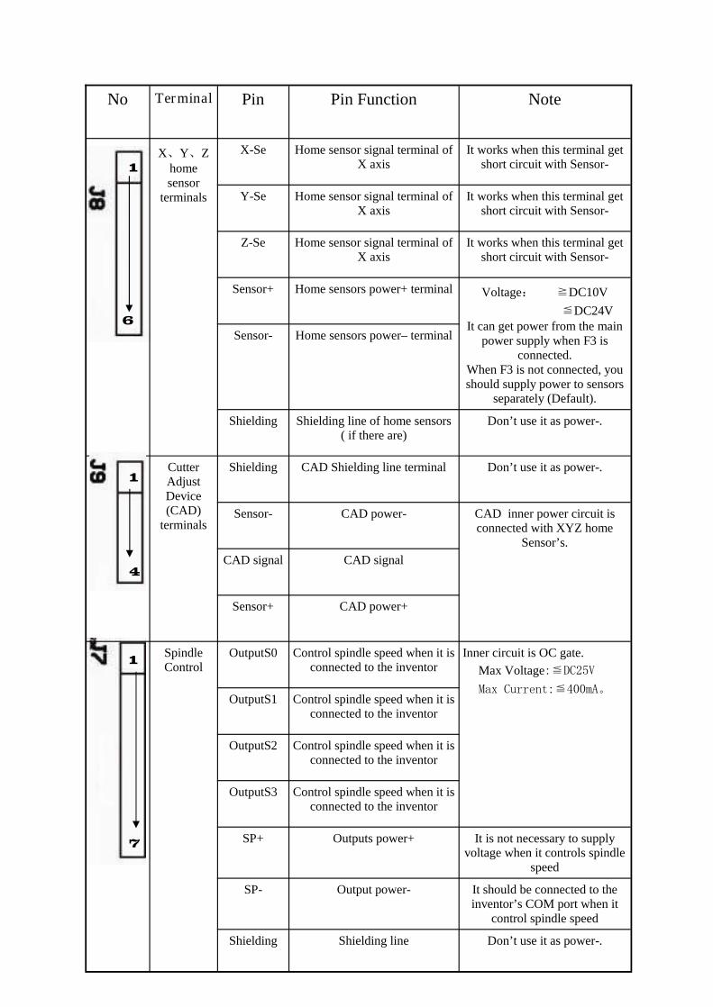
No Terminal Pin Pin Function Note
X、Y、Zhomesensor
terminals
X-Se Home sensor signal terminal ofX axis
It works when this terminal getshort circuit with Sensor-
Y-Se Home sensor signal terminal ofX axis
It works when this terminal getshort circuit with Sensor-
Z-Se Home sensor signal terminal ofX axis
It works when this terminal getshort circuit with Sensor-
Sensor+ Home sensors power+ terminal Voltage: ≧DC10V≦DC24V
It can get power from the mainpower supply when F3 is
connected.When F3 is not connected, youshould supply power to sensors
separately (Default).
Sensor- Home sensors power–terminal
Shielding Shielding line of home sensors( if there are)
Don’t use it as power-.
CutterAdjustDevice(CAD)
terminals
Shielding CAD Shielding line terminal Don’t use it as power-.
Sensor- CAD power- CAD inner power circuit isconnected with XYZ home
Sensor’s.CAD signal CAD signal
Sensor+ CAD power+
SpindleControl
OutputS0 Control spindle speed when it isconnected to the inventor
OutputS1 Control spindle speed when it isconnected to the inventor
OutputS2 Control spindle speed when it isconnected to the inventor
OutputS3 Control spindle speed when it isconnected to the inventor
SP+ Outputs power+ It is not necessary to supplyvoltage when it controls spindle
speed
SP- Output power- It should be connected to theinventor’s COM port when it
control spindle speed
Shielding Shielding line Don’t use it as power-.
Inner circuit is OC gate.Max Voltage:≦DC25V
Max Current:≦400mA。
1
6
1
4
1
7
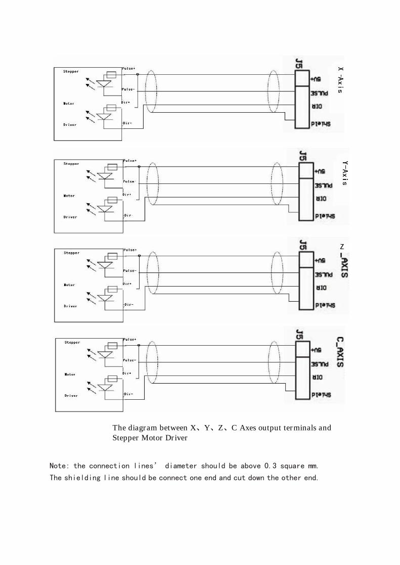
The diagram between X、Y、Z、C Axes output terminals andStepper Motor Driver
Note: the connection lines’ diameter should be above 0.3 square mm.
The shielding line should be connect one end and cut down the other end.
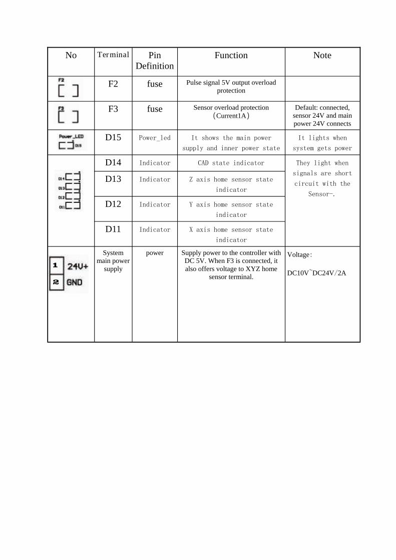
No Terminal PinDefinition
Function Note
D15 Power_led It shows the main power
supply and inner power state
It lights when
system gets power
D14 Indicator CAD state indicator
D13 Indicator Z axis home sensor state
indicator
D12 Indicator Y axis home sensor state
indicator
D11 Indicator X axis home sensor state
indicator
Systemmain power
supply
power Supply power to the controller withDC 5V. When F3 is connected, italso offers voltage to XYZ home
sensor terminal.
Voltage:
DC10V~DC24V/2A
They light when
signals are short
circuit with the
Sensor-.
F2 fuse Pulse signal 5V output overloadprotection
F3 fuse Sensor overload protection(Current1A)
Default: connected,sensor 24V and mainpower 24V connects
1
2
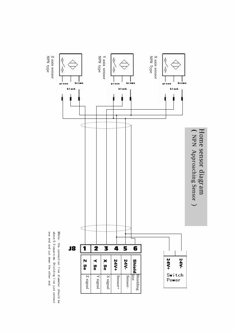
J8 1 2 3 4 5 6
Z_S
e
Y_S
e
X_S
e
24
V+
24
V-
Sh
ield
Zsign
al
Ysign
al
Xsign
al
Sensor+
Sensor-
Zaxis
sensor
NPN
type
Yaxis
sensor
NPN
type
Xaxis
sensor
NPN
Type
N0ote:the
connectionline
diametershould
be
above0.3
squaremm.
Shieldingline
justconnect
oneend
andcut
downthe
otherend.
Hom
esensor
diagram(
NPN
Approaching
Sensor)
Shield
ing
line
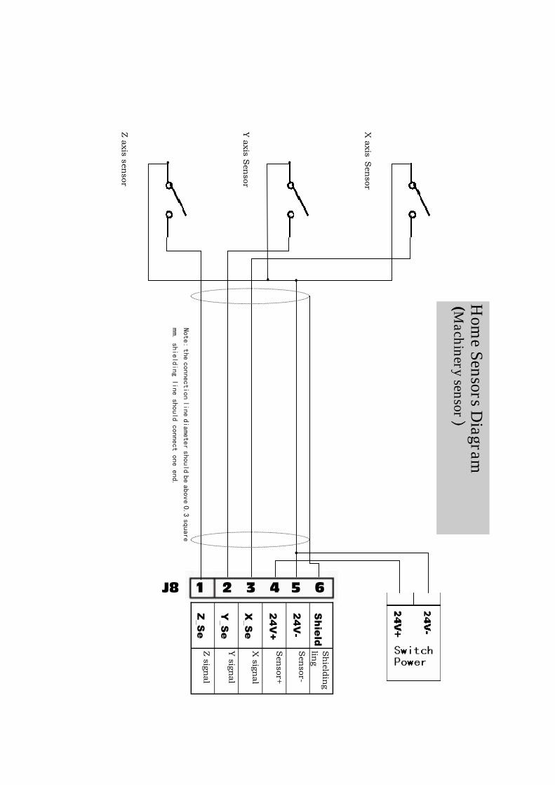
J8 1 2 3 4 5 6
Z_S
e
Y_S
e
X_S
e
24
V+
24
V-
Sh
ield
Zsign
al
Ysign
al
Xsign
al
Sensor+
Sensor-
Shield
ing
ling
Zaxis
sensor
Yaxis
Sensor
Xaxis
Sensor
Note:the
connectionline
diametershould
beabove
0.3square
mm.shielding
lineshould
connectone
end.
Hom
eSensors
Diagram
(Machinery
sensor)
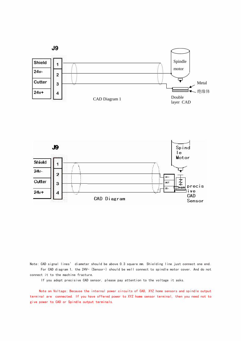
J9
Shield
24v-
Cutter
24v+Doublelayer CAD
Metal
绝缘体
Spindle
motor1
2
3
4CAD Diagram 1
Note: CAD signal lines’ diameter should be above 0.3 square mm. Shielding line just connect one end.
For CAD diagram 1, the 24V- (Sensor-) should be well connect to spindle motor cover. And do not
connect it to the machine fracture.
If you adopt precisive CAD sensor, please pay attention to the voltage it asks.
Note on Voltage: Because the internal power circuits of CAD, XYZ home sensors and spindle output
terminal are connected. If you have offered power to XYZ home sensor terminal, then you need not to
give power to CAD or Spindle output terminals.
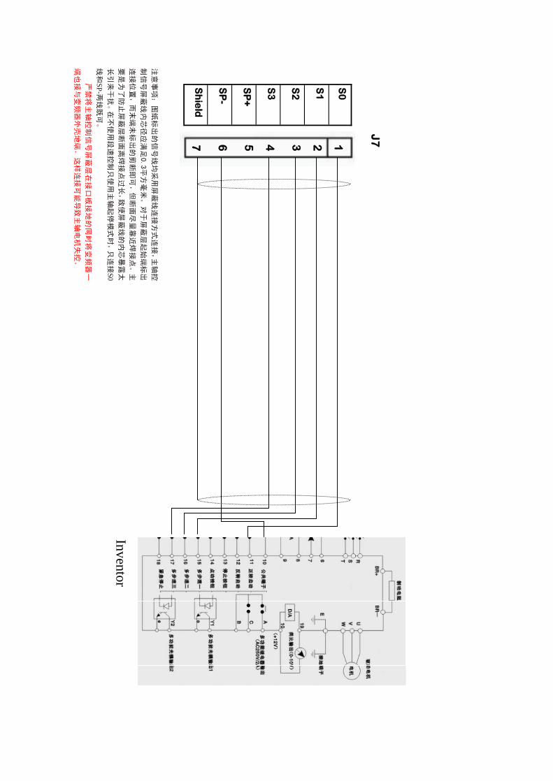
J7
S0
S1
S2
S3
SP
+
SP
-
Shield
1234567
注意
事项:
图纸标
出的信
号线均
采用
屏蔽
线连
接方式
连接
,主
轴控
制信
号屏
蔽线
内芯
径应
满足
0.3平方
毫米
。对
于屏
蔽层
起始
端标出
连接
位置,而
末端
未标
出的
剪断即可
,但
断面
尽量靠
近焊
接点
。主
要是
为了防
止屏蔽
层断面
离焊接
点过
长,致
使屏
蔽线的
内芯暴
露太
长引
来干扰
。在
不使
用段
速控制
只使
用主
轴起
停模式
时,只
连接
S0线
和SP-两
线既可
。
严禁
将主
轴控
制信
号屏
蔽层
在接
口板
接地
的同
时将
变频
器一
端也
接与变
频器外
壳地端
。这样
连接
可能
导致
主轴电
机失控
。
Inventor
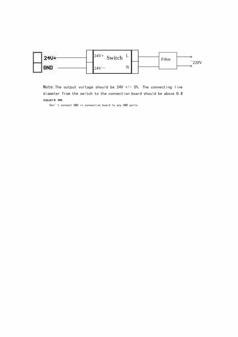
Switch24V+
24V-
L
N
Filter~220V
Note:The output voltage should be 24V +/- 5%. The connecting line
diameter from the switch to the connection board should be above 0.8
square mm.Don’t connect GND in connection board to any GND ports.