Embed Size (px)
Citation preview
UCRL-6492-T
DIAGNOSTIC TECHNIQUES OF THE HIGH COMPRESSION
AND NEUTRAL INJECTION EXPERMENTS*Willian F. Cummins
Lawrence Radiation Laboratory, University of California
Livermore, California
Summary
In the Multi-Stage Compression Experiment(Toy Top III) we wish to determine the energyand spatial distribution of the plasma com-ponents - ions and electrons - from the time oftheir initial injection into the machine throughthe heating and containment cycle. An ionanalyzer, consisting of a magnetic momentumanalyzer followed by an electrostatic analyzer,has been valuable in finding the energy distri-bution of the plasma ions. The density distri-of the plasma in the experiment's magneticfield has been largely determined with electro-static extraction probes. Microwave radiometemand double probes have been utilized to findelectron temperatures. i6 (Eu) and plasticscintillation counters assess the total numberand rate of production of neutrons from D-Dreactions, which may be confirmed with nuclearemulsions. Electron temperatures in the Single-Stage High Compression Experiment (Table Top II)have been determined from an analysis of theescaping electron flux.
The initial experiments on neutral atominjection into a mirror field geometry (ALICE)require a knowledge of the initial backgroundgas density, neutral beam current, buildup ofplasma density, loss rate from the confinementregion, and the spatial distribution of theplasma. A magnetically shielded, nude Bayard-Alpert gauge determines the total initial gaspressure, the partial pressure of each atomicspecie being found with a mass spectrograph.A copper target calorimeter indicates beamcurrent; while neutral particle detectors onthe chamber walls and screened Faraday col-lectors outside of the mirrors show the build-up and loss of plasma. These instruments,along with electrostatic probes, give thedensity of the plasma at various points in thesystem.
Introduction
Out of the great number of plasma diag-nostic methods employed at Lawrence RadiationLaboratory on the various controlled fusionexperiments, I would like to discuss a fewwhich are in use on the so-called high com-pression experiments and on the neutral in-
Work performed under the auspices of theU. S. Atomic Energy Commission.Received by the Program Committee, July 5, 1961,through :IRE. To be presented as paper No. 4-3at the Joint N4uclear Instrumentation Symposium,Raleigh, N. C.; September 7, 1961.
jection experiment. These two types of ex-periments, while differing greatly in theirmode of operation, are both characterized bythe fact that they are concerned with theheating and containment of relatively lowdensity plasmas. Compared with the 1016 -10l7/cm3 densities of fusion experimentswhich start with a few microns of cold gaspressure the maximum densities in these de-vices are never greater than 1-5 x 101/cm5.Certain experimental procedures can be usedin this density regime, which are inoperableat higher densities. Conversely, other tech-niques which are extremely useful at highdensities are of limited applicability atdensities of 1014/cm3 or less. In particu-lar, those measutrements which require theassumption of thermodynamic equilibrium orMaxwellian ion energy distribution for theirinterpretation.
High Compression ExperimentsIf a relatively cold plasma is injected
into a low magnetic field., and the field issubsequently raised to a high value, work willbe done on the plasma; and it will be heatedand compressed. This process is termed adia-batic heating if the field changes slowlywith respect to an ion cyclotron period yetfaster than the relaxation time of the ions.Devices for investigating this process aretermed High Compression Experiments; becauseplasma volume is greatly decreased as thefield rises. At Livermore there ari two ex-periments of this nature: Table Top and ToyTop.2 Table Top compresses the injectedplasma in a simple mirror field geometry,while Toy Top utilizes three stages of com-pression.
In the Multi-Stage Experiment (Toy TopIII) under the direction of F. H. Coensgen,the plasma is transferred into progressivelysmaller diameter vacuum vessels as the fieldis raised. This affords one a large savingin the amount of stored energy required forthe pulsed magnets; as the higher the field,the smaLLer the volume which it must fill.Also, an extremely useful diagnostic advantageensues; since the plasma may be heated andcompressed in one region of the vacuum cham-ber and measurements made in another. This,
71
UCRL-6492-T
of course, permits the heating process to takeplace without interference from the instru-mentation.
In the multi-stage experiment we wish tofind the energy and spatial distribution of theplasma ions and electrons from the time of theirinjection into the machine through the heatingand containment cycle. The energy distributionof the ions must be measured in detail as theircollision rates are too slow to permit as-sumption of a Maxwellian distribution. On theother hand, local equilibrium will be reachedby the electrons; so that a temperature measure-ment is adequate to describe their energydistribution.
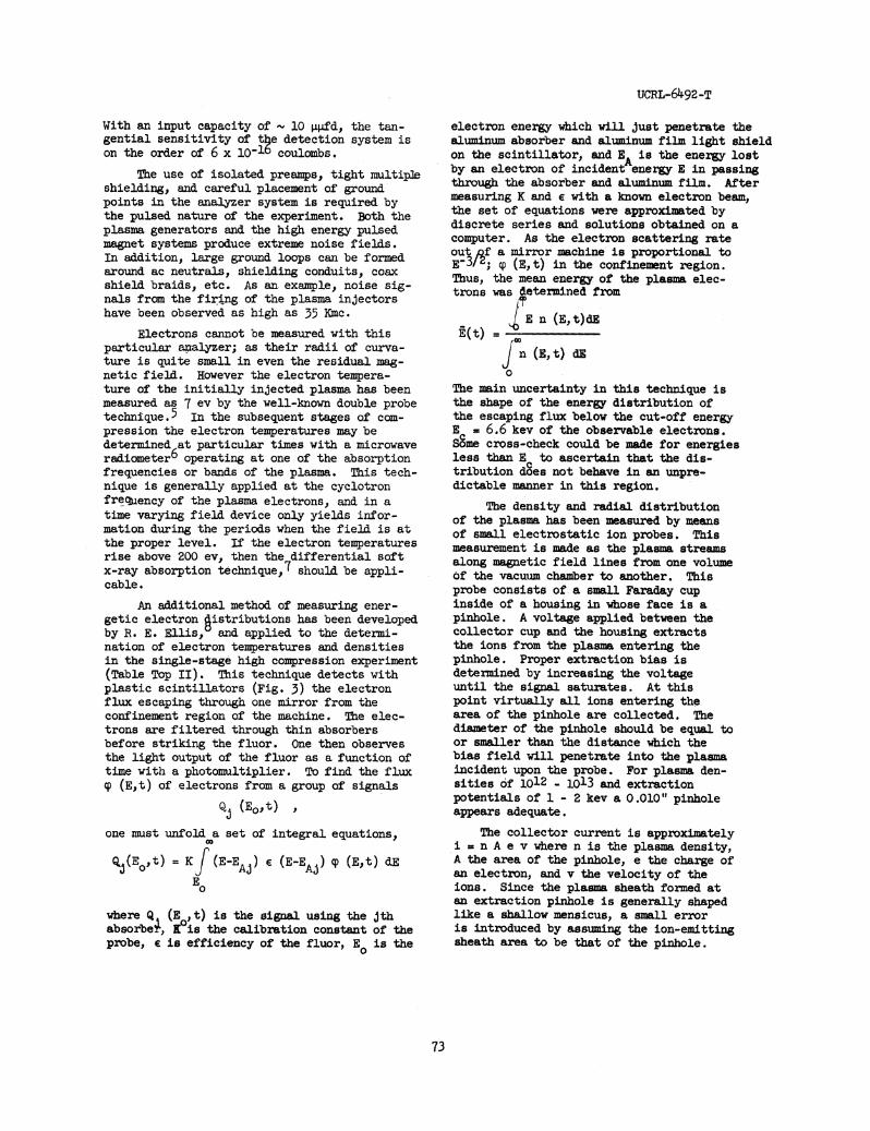
A combination magnetic and electrostaticanalyzer shown schematically in Fig. 1 has beenutilized in assessing the energy of the plasmaions as injected into the experimental volumeand as they are heated. This device consistsof a magnetic field which will separate theincoming charged particles according to theirmomnentum, followed by an electrostatic ana-lyzer which determines the particle's energy.We are, thus, able to ascertain the energy ande/m ratio of the incoming ions.
For an analyzer of this sort to work pro-perly the density of the plasma beam arrivingat the magnetic deflector must be low enoughthat the polarization potential set up. inseparating the ions from the electrons and thespace charge potential in the beam is negli-gible compared with the energy of the ions beirgmeasured. Otherwise, the ions will suffer adeflection,
23; 1 |r E x B/B2 dtc0
normal to the desired path in the time X duringwhich they transverse the magnetic field.
1 -' 2E x B/B
is the drift velocity and E is the polarizationand space charge field.
Experimentally., we have found that in ananalyzer with a momentum resolutin AP/p 3-5%one must hold the ion beam to 10-0 amperes orless; otherwise the resolution deterioratesrapidly.
To do this a collimtor consisting of a
O.qo0" x 1/8" slit and a 0.020" x 1/i8" slit,separated 2", is used for the input of theanalyzer. Also, the analyzer is placed at theend of an extension of the main vacuum chamberwhere the machine's magnetic field has fallen
to a few gauss. In this manner the plasmadensity at the input collimator is greatlyreduced as the plasma expands out of the mainfield. Also, the ions'momentum perpendi-cular to the field in the experiment istransformed into longitudinal momentum; sothat one measures the total momentum of theparticle.
In the analyzers used to date the mag-netic field is formed in the 1" gap of apair of 5" diameter pole pieces. These aremounted, with their vacuum sealed coils, ina soft iron pot which serves as both theflux return path and as the vacuum chamber.In the single channel analyzer shown theions are bent through 450 with a radius ofcurvature of 20 cm. A six-channel analyzerhas also been used.
After being magnetically analyzed theions pass on to a repel grid system, as inFig. 1 which gives an integral energy analy-sis, i.e., it only passes those ions whoseenergy is greater than that set on a repelgrid. This analyzer consists simply of aground plane grid followed by a bias orrepel grid. A plate, in front of which isa secondary electron suppressor grid, col-lects the ions.
Twio parallel plates with a uniformelectric field between them have also beenused as an electrostatic energy analyzer.3The ions entering an input slit in one platefollow a parabolic trajectory in the fieldbetween the plates and exit from a secondslit in the same plate. This type ofelectrostatic analyzer, while producing adifferential spectrum with good resolution,suffers from low transmission which makesthe problem of detection difficult.
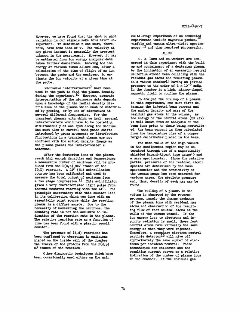
Figure 2 indicates the electrical hook-up of the repel type analyzer. As mentionedbefore, a potential is set on the repel gridto reflect ions of lower energy than thoseunder study (usually deuterium). The chargecollected is stored in the capacitance ofthe collector plate and input circuit of thepre-amplifier. A VX-55 electrometer triode,connected as a cathode follower, drives the105 ohm input impedance of a4transistorizedBurr-Brown Decade Amplifier. These twoamplifiers in turn drive a length of 125 Qcable (RG-63/u) to an oscilloscope. Sincethe ion charge collected is generally inthe form of a short (10-20 ,isec) currentpulse, the circuits must have short enoughrise time to faithfully reproduce the in-coming charge pulse. Thus, the cathodefollower connection of the electrometer whichhas a step response of approximately 1 isec.
72
UCRL-6492-T
With an input capacity of - 10 gopd, the tan-gential sensitivity of t e detection system ison the order of 6 x 1l-1o coulombs.
The use of isolated preamps, tight multip3eshielding, and careful placement of groundpoints in the analyzer system is required bythe pulsed nature of the experiment. Both theplasma generators and the high energy pulsedmagnet systems produce extreme noise fields.In addition, large ground loops can be formedaround ac neutrals, shielding conduits, coaxshield braids, etc. As an example, noise sig-nals from the firing of the plasma injectorshave been observed as high as 35 Kmc.
Electrons cannot be measured with thisparticular airalyzer; as their radii of curva-ture is quite small in even the residual mag-netic field. However the electron tempera-ture of the initially injected plasma has beenmeasured as 7 ev by the well-known double probetechnique.5 In the subsequent stages of com-pression the electron temperatures may bedetermined6at particular times with a microwaveradiometer operating at one of the absorptionfrequencies or bands of the plasma. This tech-nique is generally applied at the cyclotronfreqjiency of the plasma electrons, and in atime varying field device only yields infor-mation during the periods when the field is atthe proper level. If the electron temperaturesrise above 200 ev, then the differential softx-ray absorption technique.,7 should be appli-cable.
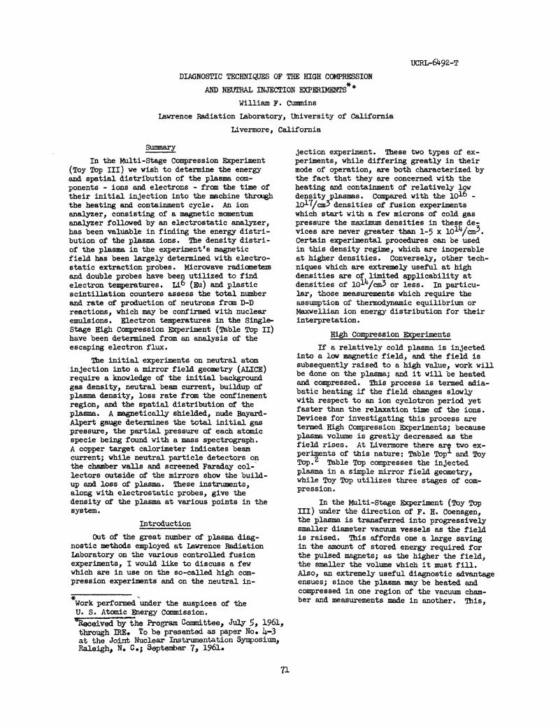
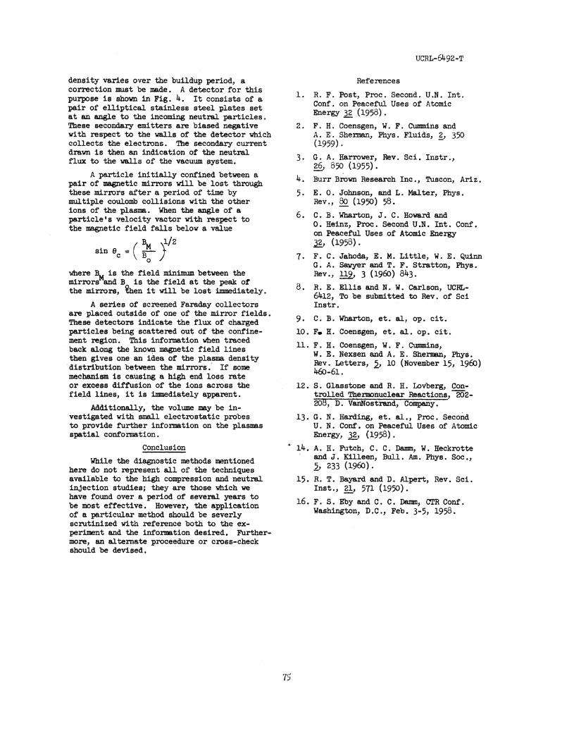
An additional method of measuring ener-getic electron istributions has been developedby R. E. Ellis, and applied to the determi-nation of electron temperatures and densitiesin the single-stage high compression experiment(Table Top II). This technique detects withplastic scintillators (Fig. 3) the electronflux escaping through one mirror from theconfinement region of the machine. The elec-trons are filtered through thin absorbersbefore striking the fluor. One then observesthe light output of the fluor as a function oftime with a photomultiplier. To find the fluxcp (E,t) of electrons from a group of signals
Q; (E ,t) ,
one must unfold a set of integral equations,
Q%(Eo0t) = K (E-EAj) e (E-EAj) qp (E,t) dE
Eo
where Q (E ,t) is the signal using the jthabsorbe+, eKis the calibration constant of theprobe, e is efficiency of the fluor, E0 is the
electron energy which will just penetrate thealuminum absorber and aluminum film light shieldon the scintillator, and B is the energy lostAby an electron of incident energy E in passingthrough the absorber and aluminum film. Aftermeasuring K and e with a known electron beam,the set of equations were approximated bydiscrete series and solutions obtained on acomputer. As the electron scattering rateout f a mirror machine is proportional toE-3/; cp (E,t) in the confinement region.Thus, the mean energy of the plasma elec-trons was etermined from
t E n (E,t)dEn (E,t) dE
0
The main uncertainty in this technique isthe shape of the energy distribution ofthe escaping flux below the cut-off energyE = 6.6 kev of the observable electrons.Some cross-check could be made for energiesless than Ec to ascertain that the dis-tribution does not behave in an unpre-dictable manner in this region.
The density and radial distributionof the plasma has been measured by meansof small electrostatic ion probes. Thismeasurement is made as the plasma streamsalong magnetic field lines from one volumeof the vacuum chamber to another. Thisprobe consists of-a small Faraday cupinside of a housing in whose face is apinhole. A voltage applied between thecollector cup and the housing extractsthe ions from the plasma entering thepinhole. Proper extraction bias isdetermined by increasing the voltageuntil the sigmal saturates. At thispoint virtualy all ions entering thearea of the pinhole are collected. Thediamter of the pinhole should be equal toor smaller than the distance which thebias field will penetrate into the plasmaincident upon the probe. For plasma den-sities of 1012 _ 1o13 and extractionpotentials of 1 - 2 kev a 0.010" pinholeappears adequate.
The collector current is approximatelyi = n A e v where n is the plasma density,A the area of the pinhole, e the charge ofan electron, and v the velocity of theions. Since the plasma sheath formed atan extraction pinhole is generally shapedlike a shallow mensicus, a small erroris introduced by assuming the ion-emittingsheath area to be that of the pinhole.
73
UCRL-6492-T
However, we have found that the shot to shotvariation in our signals make this error un-important. To determine n one must, there-fore, have some idea of v. The velocity atany given instant is generally the greatestunknown in the measurement. However, it maybe estimated from ion energy analyzer datataken farther downstream. Knowing the ionenergy at various times allows one, after acalculation of the time of flight of an ionbetween the probe and the analyzer, to es-timate the ion velocity at a given time atthe probe.
Microwave interferometers9 have beenused in the past to find the plasm densityduring the experiment.lO However, accurateinterpertation of the microwave data dependsupon a knowledge of the radial density dis-tribution of the pla which must be determin-ed by probing, or by use of microwaves atseveral different frequencies. For thetransient plasmas with which we deal; severalinterferometers would have to be operatingsimultaneously at one spot along the machine.One must also be careful that phase shiftsintroduced by gross movements or distributionfluctuations in a transient plasma are notconfused with the actual density change asthe plasma passes the interferometer'santennae.
After the deuterium ions of the plasmareach high enough densities and temperaturesa measurable number of neutrons will be pro-duced from the D(d,n) He3 branch of the(D, D) reaction. A Li6 (Eu) scintillationcounter has been calibrated and used tomeasure the total output of neutrons froma two stage compression.11 This scintillatorgives a very characteristic light pulse fromthermal neutrons reacting with the Li6. Theprinciple uncertainty with this counter liesin its calibration which was done with anessentially point source while the reactingplasma is a diffuse source. Due to thenecessity of moderating the neutrons, thecounting rate is not too accurate an in-dication of the reaction rate in the plasma.The relative reaction rate as a function oftime has been found with a plastic recoilcounter.
The presence of (d, d) reactions hasbeen confirmed by observing in emulsionsplaced on the inside wall of the chamberthe tracks of the protons from the D(d,p)H3 branch of the reaction.
Other diagnostic tecbniques which havebeen occasionally used either on the main
multi-stage experiment or on connect-experiments include magnetic probes,visible and vacuum ultra-violet spectro-scopy,13 and time resolved photography.
ALICE
C. C. Damm and co-workers are con-cerned in this experiment with the buildup and containment of a deuterium plasmaby the ionization of an energetic neutraldeuterium atomic beam colliding with theresidual gas atoms and resulting plasmin a vacuum chamberl4 having an initialpressure on the order of 1 x 10⁻⁹ mmHg.In the chamber is a high, mirror-shapedmagnetic field to confine the plasma.
To analyze the buildup of a plasmain this experiment, one must first de-termine the injected beam current andthe number density and mass of theresidual gas atoms in the volume. Asthe energy of the neutral atoms (20 kev)is well known from an analysis of thebeam ions prior to their being neutraliz-ed, the beam current is then calculatedfrom the temperature rise of a coppertarget calorimeter placed in the beam.
The mean value of the high vacuumin the confinement region may be de-termined through use of a magneticallyshielded Bayard-Alpert type gaugel5 anda mass spectrometer. Since the relativepartial pressures of the residual atomicspecies are determined by the massspectrometer and the sensitivity ofthe vacuum gauge has been measured forvarious gases, the absolute pressureand, thus, density of each gas may befound.
The buildup of a plasma in thevolume is observed by the reverseprocess, namely the charge exchangeof the plasma ions with residual gasatoms and observation of the result-ing flux of fast neutral atoms at thewalls of the vacuum vessel. If theion energy loss to electrons and im-purity radiation is small, these fastneutral atoms have virtually the sameenergy as when they were injected.Therefore, a secondary electron neutralparticle detector16 will give offapproximately the same number of elec-trons per incident neutral. Thesesecondar#-es are collected and theresulting current serves as a relativeindication of the number of plasma ionsin the chbaber. If the residual gas
74
UCRL-6492-T
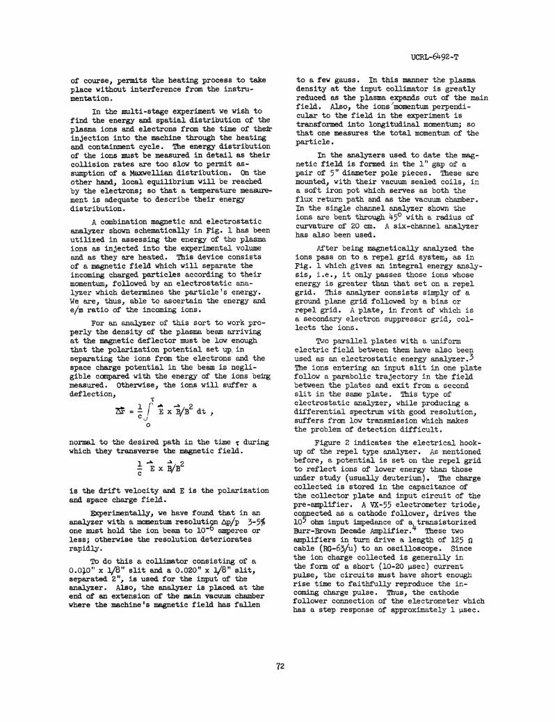
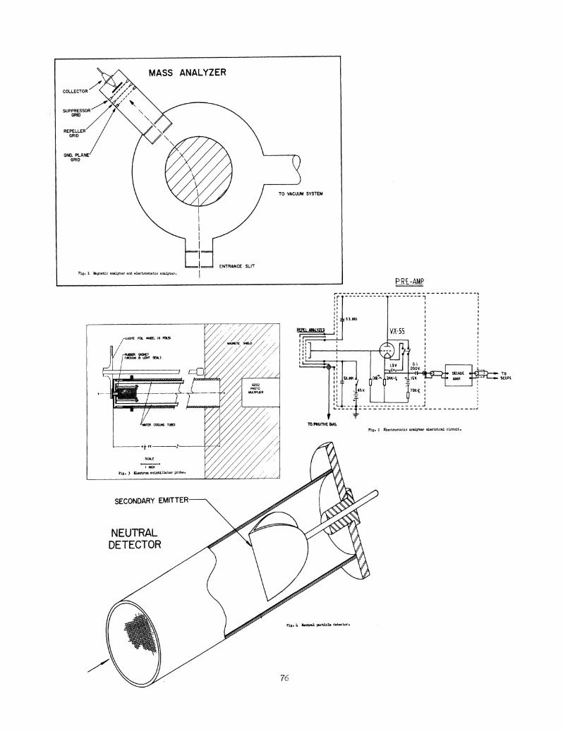
density varies over the buildup period, acorrection must be made. A detector for thispurpose is shown in Fig. 4. It consists of apair of elliptical stainless steel plates setat an angle to the incoming neutral particles.These secondary emitters are biased negativewith respect to the walls of the detector whichcollects the electrons. The secondary currentdrawn is then an indication of the neutralflux to the walls of the vacuum system.
A particle initially confined between apair of magnetic mirrors will be lost throughthese mirrors after a period of time bymultiple coulomb collisions with the otherions of the plasma. When the angle of aparticle's velocity vactor with respect tothe magnetic field falls below a value
BM 1/2sine
where B is the field minimum between themirrors and B is the field at the peak ofthe mirrors, &hen it will be lost immediately.
A series of screened Faraday collectorsare placed outside of one of the mirror fields.These detectors indicate the flux of chargedparticles being scattered out of the confine-ment region. This information when tracedback along the known magnetic field linesthen gives one an idea of the plasma densitydistribution between the mirrors. If somemechanism is causing a high end loss rateor excess diffusion of the ions across thefield lines, it is immediately apparent.
Additionally, the volume may be in-vestigated with small electrostatic probesto provide further information on the plasmasspatial conformation.
Conclusion
While the diagnostic methods mentionedhere do not represent all of the techniquesavailable to the high compression and neutralinjection studies; they are those which wehave found over a period of several years tobe most effective. However, the applicationof a particular method should be severlyscrutinized with reference both to the ex-periment and the information desired. Further-more, an alternate proceedure or cross-checkshould be devised.
References
1. R. F. Post, Proc. Second. U.N. Int.Conf. on Peaceful Uses of AtomicEnergy 32 (1958).
2. F. H. Coensgen, W. F. Cummins andA. E. Sherman, Phys. Fluids, 2, 350(1959).
3. G. A. Harrower, Rev. Sci. Instr.,26, 850 (1955).
4. Burr Brown Research Inc., Tuscon, Ariz.
5. E. 0. Johnson, and L. Malter, Phys.Rev., 80 (1950) 58.
6. C. B. Wharton, J. C. Howard and0. Heinz, Proc. Second U.N. Int. Conf.on Peaceful Uses of Atomic Energy32, (1958).
7. F. C. Jahoda, E. M. Little, W. E. QuinnG. A. Sawyer and T. F. Stratton, Phys.Rev.., 119, 3 (1960) 843.
8. R. E. Ellis and N. W. Carlson, UCRL-6412, To be submitted to Rev. of SciInstr.
9. C. B. Wharton, et. al, op. cit.
10. F. H. Coensgen, et. al. op. cit.
11. F. H. Coensgen, W. F. Cummins,W. E. Nexsen and A. E. Sherman, Phys.Rev. Letters, 2, 10 (November 15, 1960)460-61.
12. S. Glasstone and R. H. Lovberg, Con-trolled Thermonuclear Reactions, 202-208, D. VanNostrand, Company.
13. G. N. Harding, et. al., Proc. SecondU. N. Conf. on Peaceful Uses of AtomicEnergy, 32, (1958).
14. A. H. Futch, C. C. Damm, W. Heckrotteand J. Killeen, Bull. Am. Phys. Soc.,5, 233 (1960).
15. R. T. Bayard and D. Alpert, Rev. Sci.Inst., 21, 571 (1950).
16. F. S. Eby and C. C. Damm, CTR Conf.Washington, D.C., Feb. 3-5, 1958.
I ~~pR E-AMPr--------------------______
sr s nIwll1 -RMLAWYLE j VX-55
Is IS1
7
L 0.1NSOV L.
II - ~~~~~~~ ~ ~~~~~DECADE * 'TOII SOUjot - O2K-4 *IV IS jO AMP. e SCOPE.
-If44 :-V. 7SK-41
TO POSITIVE IausFig. 2 Fi,gtrs~ttic anslger electrical circft.
SECONDARY El
NEUTRALDETECTOR
Fig. is4 Neutral ptle detOcto.r
76