Embed Size (px)
Citation preview

1
DIAGNOSTIC
SERVICE MANUAL
Form No. 3308058.001 11/02©2002Dometic CorporationLaGrange, IN 46761

2
Contents PAGE NO.WeatherPro & Oasis Elite Symptom/Cause ........................................... 3
SECTION 1- Wiring .................................................................................. 4-51.1 12VDC Supply Wire ................................................................. 41.2 Wire From Control Box To Awning ................................................... 41.3 Wire Inside Hardware Channel (WeatherPro Only) ......................... 41.4 Motor Connection & Motor ............................................................... 41.5 Wire To Remote Switch ................................................................... 51.6 Wind Sensor Cable .......................................................................... 51.7 Ignition Interlock wire ....................................................................... 5
SECTION 2- WeatherPro Wind Sensor ................................................... 62.1 Wind Sensor .................................................................................... 6
SECTION 3- Control Box ......................................................................... 6-73.1 Circuit Board ................................................................................... 6-73.2 Control Box Rocker Switch .............................................................. 73.3 Wind Sensor Toggle Switch ............................................................. 73.4 Wiring Diagram ............................................................................... 6-7
SECTION 4- Remote Switch .................................................................... 74.1 Remote Switch ................................................................................ 7
SECTION 5- Remote Key FOB ................................................................. 75.1 Remote Key FOB ............................................................................. 75.2 FOB Programming ........................................................................... 8
SECTION 6- WeatherPro Auxiliary Cable ............................................... 86.1 Auxiliary Cable ................................................................................. 8
SECTION 7- WeatherPro Emergency Retract Procedure ..................... 8-97.1 Emergency Retract Procedure ....................................................... 8-9
SECTION 8- WeatherPro Fabric, Roller Tube, Torsion Assembly& Weathershield Replacement .............................................................. 9-138.1 General Instructions ........................................................................ 98.2 Awning Removal ............................................................................ 9-108.3 Left Hand Torsion Removal .......................................................... 10-118.4 Right Hand Drive Assembly Removal ..............................................118.5 Fabric Removal From Roller Tube ...................................................118.6 Weathershield Assembly Removal And Replacement .....................118.7 Re-install Fabric On Roller Tube..................................................... 128.8 Torsion Assembly Replacement.................................................... 12-138.9 Left Hand Torsion Assembly Winding ............................................. 13
SECTION 9- Wiring Diagram................................................................... 149.1 Wiring Diagram .............................................................................. 14

3
SYMPTON CAUSE LOCATION
1. Awning will not open 1. 12VDC Supply Wire Section 1.12. Fuse Section 3.1.33. Ignition Interlock (WeatherPro) Section 1.7 & 3.1.74. Wiring/Connections Section 1.2, 1.3, 1.4.1, 1.5 & 9.15. Wind (WeatherPro) Section 2.1 & 3.36. Circuit Board Wiring Section 3.1-3.47. Motor Section 1.4.2
2. Awning will not close 1. 12VDC Supply Wire Section 1.12. Fuse Section 3.1.33. Wiring/Connections Section 1.2, 1.3, 1.4, 1.5, & 9.14. Circuit Board Wiring Section 3.1-3.45. Motor Section 1.4.2
3. Awning works with remote switch 1. Distance Section 5.1but not key FOB (WeatherPro Only) 2. Key FOB Battery Section 5.1
3. Key FOB Programming Section 5.2
4. Awning works with key FOB but not 1. Circuit Board Wiring Section 3.1.5 & 3.1.6remote switch (WeatherPro Only) 2. Switch Section 4.1
5. Awning will open when ignition key is in 1. Wiring/Connections Section 1.7the on position (WeatherPro Only) 2. Circuit Board Section 3.1.7
6. Awning works in opposite direction 1. Wiring/Connections Section 1.52. Circuit Board Wiring Section 3.1.5 & 3.1.63. Switch Section 4.1 & 3.2
7. WeatherPro awning works when Oasis 1. Wiring/Connections Section 1.2 & 9.1Elite should or visa versa 2. Circuit Board Wiring Section 3.1.4
8. Awning does not close during high wind 1. Wind Sensor Switch Off Section 3.3conditions 2. Wind Sensor Wiring Section 1.6 & 3.1.8
3. Wind Sensor Section 2.1
9. Beeping sound coming from control box 1. Wind Sensor Wiring Section 3.1.8(WeatherPro Only) 2. Wind Sensor Section 2.1
10. Auxiliary Close/Open awning 1. No 12VDC in RV Section 6.1(WeatherPro Only)
11. Emergency Close Awning 1. No 12VDC Available Section 7.1(WeatherPro Only) 2. Awning Inoperable Section 7.1
12. Fabric, Roller Tube, Torsion Assembly Section 8.1- 8.9and Weathershield Replacement(WeatherPro Only)
4
SECTION 1 WIRING1.1 12VDC Supply Wire
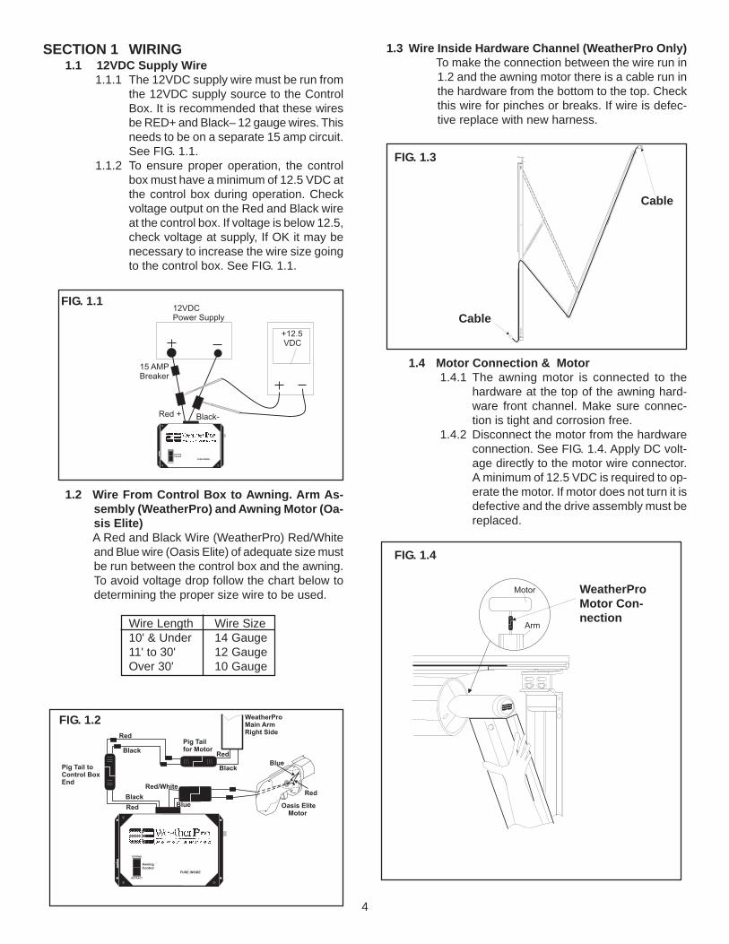
1.1.1 The 12VDC supply wire must be run fromthe 12VDC supply source to the ControlBox. It is recommended that these wiresbe RED+ and Black– 12 gauge wires. Thisneeds to be on a separate 15 amp circuit.See FIG. 1.1.
1.1.2 To ensure proper operation, the controlbox must have a minimum of 12.5 VDC atthe control box during operation. Checkvoltage output on the Red and Black wireat the control box. If voltage is below 12.5,check voltage at supply, If OK it may benecessary to increase the wire size goingto the control box. See FIG. 1.1.
1.2 Wire From Control Box to Awning. Arm As-sembly (WeatherPro) and Awning Motor (Oa-sis Elite)A Red and Black Wire (WeatherPro) Red/Whiteand Blue wire (Oasis Elite) of adequate size mustbe run between the control box and the awning.To avoid voltage drop follow the chart below todetermining the proper size wire to be used.
Wire Length Wire Size10' & Under 14 Gauge11' to 30' 12 GaugeOver 30' 10 Gauge
EXTEND
RETRACT
AwningControl
FUSE INSIDE
WeatherProMain ArmRight Side
Pig Tail toControl BoxEnd
Pig Tailfor Motor
Oasis EliteMotor
Black
Red
Red
Black
Red/White
Blue
Black
Red Blue
Red
FIG. 1.2
1.3 Wire Inside Hardware Channel (WeatherPro Only)To make the connection between the wire run in1.2 and the awning motor there is a cable run inthe hardware from the bottom to the top. Checkthis wire for pinches or breaks. If wire is defec-tive replace with new harness.
1.4 Motor Connection & Motor1.4.1 The awning motor is connected to the
hardware at the top of the awning hard-ware front channel. Make sure connec-tion is tight and corrosion free.
1.4.2 Disconnect the motor from the hardwareconnection. See FIG. 1.4. Apply DC volt-age directly to the motor wire connector.A minimum of 12.5 VDC is required to op-erate the motor. If motor does not turn it isdefective and the drive assembly must bereplaced.
FIG. 1.4
+12.5VDC
EXTEND
RETRACT
AwningControl
FUSE INSIDE
12VDCPower Supply
15 AMPBreaker
Red + Black-
FIG. 1.1
FIG. 1.3
Cable
Cable
Motor
Arm
WeatherProMotor Con-nection

5
1.7 Ignition Interlock WireThe ignition Interlock wire when correctly installedwill prevent the awning from opening when theignition key is in the on position. This wire is routedbetween the ignition isolator (Pink) wire of thecontrol box to the ignition isolator of the vehicle.It should be a 16 gauge wire. Make sure wireconnections are tight and corrosion free.
1.5 Wire To Remote SwitchThe remote switch is connected to the controlbox with three (3) 16 gauge wires. These areBrown, Yellow, Green for WeatherPro and Brown/White, Yellow/White, Green/White for Oasis Elite.The switch end of the wire will be connected tothe switch by means of 1/4" insulated tab con-nectors. The control box end has a pig tail toconnect the control box to these three wires. Seeswitch for correct wiring. Make sure connectionsare tight and corrosion free.
1.6 Wind Sensor CableThe wind sensor is connected to the control boxwith a FLAT four (4) conductor cable terminatedon both ends with an RJ-11 telephone connec-tor. Maximum length is 18'. This cable is polaritysensitive and must be assembled as shown. Astandard telephone cable will not work. Cablecan be checked with a Dometic 3107127.007cable tester. If cable is found to be defective re-place with a cable no longer than 18'
EXTEND
RETRACT
AwningControl
FUSE INSIDE
WeatherProRemoteSwitch
EXTEND
RETRACT
Pig Tail toRemote Switch
Oasis EliteRemoteSwitch
Bro
wn
/Wh
ite
Gre
en
/W
hit
eYe
llo
w/W
hit
e
Green
Yellow
Brown
Green
Yellow
Brown
EXTEND
RETRACT
Bro
wn
Wh
ite Green/ White
Yellow/White
Pig Tail toRemote Switch
FIG. 1.5
FIG. 1.6
Red
4 ConductorFLAT CableConnections
Bla
ck
Gre
enY
ello
w
Bla
ck
Gre
en
Pin 1
RJ-11 Connector
Flat Four Conductor Cable
FIG. 1.6 cont.
Red
Yel
low
EXTEND
RETRACT
AwningControl
FUSE INSIDE
+IgnitionIsolatorPink
FIG. 1.7

6
SECTION 2 Wind Sensor2.1 The wind sensor monitors the wind speed and
sends a signal to the control box if wind speedsexceeds the preset setting. The correct positionof the winds sensor is critical. It shoud be within3 feet of the right side top mounting bracket andaway from other objects. To check out the windsensor, extend the awning and place the windsensor switch in the ENABLE (ON) position. Youcan create sufficient amount of wind by placing astandard hair dryer approximately 6 inches awayfrom the wind sensor with the dryer set on HIGHand NO HEAT. The awning should close auto-matically.
12 VDCSupply
Wind Sensor SwitchENABLE (ON)DISABLE (OFF)
Re
d/W
hite
Blu
e
Black 12VDC -
Re
d1
2V
DC
+
T1 T2 T3 T4 T5 T6 T7 T8 T9
15
AM
P
FU
SE
T10 T11 T12 T13 T14 T15 T16 T17 T18 T19 T20
EXTEND
RETRACT
Brown WhiteG
ree
n/W
hite
Ye
llow
/Wh
ite
Green
Brown
Yellow
Blue
Blue
Pin
k
Green
YellowBrown
Re
d
Bla
ck
Cable to Wind Sensor(18 Foot Maximum)
WeatherProOutput
Oasis EliteOutput
Oasis EliteRemoteSwitch
WeatherProRocker Switch WeatherPro
RemoteSwitch
SECTION 3 Control BoxThe control box is the heart of the system andcontains a fuse, rocker switch, wind sensor toggleswitch & circuit board.
3.1 Circuit BoardThe circuit board can be checked out by the pro-cess of elimination. Make sure there is 12.5 VDCgoing into the circuit board.3.1.1 Disconnect all pig tails coming out of the
control box.3.1.2 Check for 12.5 VDC (minimum) at T1 (red
+) and T3 (black –) on circuit board.3.1.3 Check for 12.5 VDC (minimum) on each
leg of fuse. Place the negative lead of thevolt meter on T3 and check each leg ofthe fuse with the positive lead. This shouldread 12.5 VDC on each leg. Replace ifdefective.
3.1.4 Check for voltage at the WeatherPro out-put pigtail (Red & Black wire). First, pressand hold the rocker switch in the extendposition. Place the negative lead of thedigital volt meter on the Black wire posi-tion of the pigtail and the positive lead ofthe volt meter on the Red wire position ofthe pigtail. The meter should read (–)negative 12.5 VDC (minimum). Do notmove the volt meter leads and press andhold the rocker switch in the retract posi-tion. The meter should read (+) positive12.5 VDC (minimum).
FIG. 3.4
FIG. 2.1
Wind Sensor Switch
Control BoxW
ind
Sensor
EN
AB
LE
DIS
AB
LE
Win
dS
en
so
r
EN
AB
LE
DIS
AB
LE

7
3.1.5 To check the WeatherPro remote switchconnection (Brown, Green, & Yellow) wireuse a jumper wire and connect the Yellowto Brown. You should hear the relay click.Then connect the Green to Brown and youshould hear another click.
3.1.6 Check the Oasis Elite remote switch wireand the output wire at the same time. Theremote switch wires are Brown/White,Green/White and Yellow/White. The out-put wire is Red/White and Blue. Connectthe positive lead of the digital volt meterto the Red/White wire position of the pig-tail and the negative to the Blue wire po-sition of the pigtail. Jump across the Yel-low/White and brown/White wire. Youshould hear the relay click and the volt-age meter should read (–) negative 12.5VDC (minimum). Jump across the Green/White and the Brown/White wire. Youshould hear another relay click and thevolt meter should read (+) positive 12 VDC(minimum).
3.1.7 To check the ignition interlock function(WeatherPro Only), apply (+) positive 12VDC to the Pink ignition interlock wire. Re-do test in 3.1.4. There should be no read-ings or relay clicks when the rocker switchis placed in the extend position or the keyFOB extend button is pressed.
3.1.8 The circuit board contains an audiblealarm to alert the user when there is aproblem with the wind sensor or windsensor cable. To test this alarm discon-nect the FLAT four (4) conductor cablefrom the side of the control box. Place thewind sensor switch in the ENABLE (ON)position. The alarm should beep from in-side the control box. If this occurs undernormal operation this would indicate aproblem with the wind sensor wire or theconnection between the wire and the cir-cuit board or the wire and the wind sen-sor. See Section 1.6 and Section 2.1.
3.2 Control Box Rocker SwitchThe awning can be operated at the control boxby using the rocker switch located on the coverof the control box. To test the switch, press ex-tend or retract and you should hear a relay click.If after all other circuit board checks are madeand no click is present switch is defective. Re-place.
3.3 Wind Sensor Toggle SwitchThe toggle switch turns the wind sensor featureon and off. When the switch is in the DISABLE(OFF) position the awning will not automaticallyretract if threating winds are present. When inthe ENABLE (ON) positiion the awning will auto-matically retract if the wind exceeds the presetsetting.If one or more of the above tests do not performproperly the circuit board is probably defective.Replace the control box assembly.
3.4 Wiring Diagram (See Page 6, FIG. 3.4)
SECTION 4 Remote Switch4.1 If awning does not work using the remote switch,
disconnect both the WeatherPro and the OasisElite pigtail. Check for 12VDC on the control boxend of the pig tail. See Section 3.1.4 and 3.1.6. Ifthere is 12 VDC at this point depress the remoteswitches and listen for the relays to click. If noclicking is heard replace appropiate remoteswitch.
SECTION 5 Remote Key FOB5.1 The remote key FOB is powered by a 12 VDC
type 23A battery. The operational range is up to30 feet. This distance will vary depending on thebattery condition. To change the battery, removescrew in back of key FOB and replace it with atype 23A 12VDC battery.
EXTEND
RETRACT
FIG. 4.1
PATIO
DOOR
EXTEND
EXTEND
RETRACT
RETRACT
23A 12V
Battery
FIG. 5.1

8
SECTION 6 Auxiliary CableIn Case Of Coach 12VDC Power Failure:6.1. The WeatherPro hardware provides an auxiliary
power cable to connect the awning motor to anexternal 12 VDC power source in case of powerfailure in the coach. A good external 12 VDCpower source would be an automobile battery.Access the motor and hardware cable connec-tion located behind the wire cover at the top ofthe right hand arm. Gently squeeze the sides to-gether to remove. Unplug the connection.SeeFIG. 6.1.
5.2 Programming Key FOBThe electronic board is susceptible to staticcharge. Do not insert metal object inside con-trol box. Damage to electronic board will oc-cur if a short is created. Use only a noncon-ductive material to depress programmingbutton inside control box.5.2.1 Remove four (4) screws from control box
cover and lift cover to expose circuitboard.See FIG 5.2.
5.2.2 Press and release programming button .Programming indicator light will illuminate.
5.2.3 Press and hold the key FOB patio awningextend button for four (4) seconds.
5.2.4 Release the key FOB patio awning extendbutton. This completes the programmingprocess.
5.2.5 Place control box cover on control box andsecure with four (4) screws .
5.2.6 Test awning operation.
FIG. 6.1
MotorConnector
10' AuxiliaryCable
HardwareConnector
WireCover
Connect the supplied 10 ft. harness directly tothe motor plug. Not the one in the hardware. Con-nect the other end of the 10 ft. harness to a 12VDC battery source. The red wire goes to + andthe black to –. This will retract the awning. Toavoid motor damage disconnect battery sourceimmediately after awning is fully retracted. Theawning can be extended by reversing the polar-ity. Place the red wire on the – and the black wireon the +. Again, remove wires immediately afterawning is fully extended.
SECTION 7 Emergency Retract ProcedureTo Manually Close Awning:7.1 Slide the pull strap (provided) into the utility slot
of the FRTA. See FIG. 7.1.
Patio AwningExtend Button
ProgrammingButton
ProgrammingIndicator Light
FIG. 5.2
ProgrammingIndicator Light Programming
Button

9
Bolt
While one person is holding onto the pull strap,remove the bolt in the top of the right top casting.The FRTA will roll in once the bolt is removed.Walk the awning to the closed position.See FIG.7.1.Align hole where bolt was removed and drive boltback into top casting to secure awning.
Bolt must be re-installed to prevent awning fromopening during travel. Have awning serviced by aDometic Service Center or a qualified service tech-nician before attempting to open awning after thisprocedure has been performed.
SECTION 8 WeatherPro Fabric, Roller Tube,Torsion Assembly &Weathershield Replacement
8.1. General Instructions8.1.1 The fabric roller tube assembly (referred
to in the instructions as a FRTA) consistsof a vinyl or acrylic fabric, roller tube, tor-sion assembly and weathershield. Theseinstructions will aid the service technicianto make repairs quickly and correct. Therepairs must be made by a qualified ser-vice technician. Read instructions EN-TIRELY before attempting to make repairson the product.
These instructions must be read and under-stood before installation, adjustment, serviceor maintenance is performed. This unit mustbe installed by a qualified service technician.Modification of this product can be extremelyhazardous and could result in personal injuryor property damage.
8.2 Awning Removal8.2.1 In all instances of fabric, roller tube or
weather shield replacement, it is neces-sary to unroll the fabric. A large clean andsmooth work area is required to preventdamage to the fabric.
Note: If replacement of either torsion assembly is requiredawning removal from the coach is not necessary. Proceedto Sections 8.3 and 8.4.
8.2.2 Remove the TEK screws securing the aw-ning fabric at each end of the awning rail.See FIG. 8.2.2.
8.2.3 Extend or open the awning two revolu-tions of the FRTA. This will allow for re-moval of top brackets and the FTRA.
8.2.4 Pin the left hand torsion. See Section 8.3.8.2.5 Disconnect the wire harness at the plug
by the lower mounting bracket of the rightarm assembly. In some installations theharness may be run through a hole in theside wall of the coach. If the hole is sealed,use a screw driver to dig out the sealant.Be careful not to damage wires, wall, orthe harness assembly out of the coach.
Note: In some installations the wind sensor wire is routedbehind the right arm assembly. Becareful not to damage.
Arms under tension from the gas strut aredangerous. Use extreme care. If not controlledthe arms will extend quickly. Keep hands andclothing clear of awning arms, as personalinjury may result.
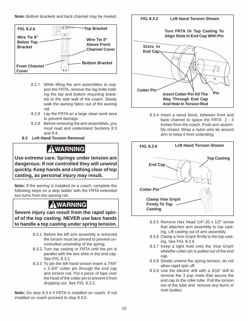
8.2.6 The next two steps require three people.Loosen the lag bolts holding the top andbottom mounting brackets to the coach.Push the arm assemblies closed and wraptwo heavy nylon wire ties around each armassembly to prevent them from extend-ing during removal of the FRTA. Oneshould be 8 inches above the front chan-nel cover, and the other 8 inches belowthe top mounting bracket. Do both armassemblies. See FIG. 8.2.6.
FIG. 7.1FIG. 8.2.2
TEK Screw
Remove fromBoth Ends
Awning Rail
10
FIG. 8.3.2
Turn FRTA Or Top Casting ToAlign Slots In End Cap With Pin
Pin
Slots InEnd Cap
Cotter PinInsert Cotter Pin All TheWay Through End CapAnd Hole In Torsion Rod
Left Hand Torsion Shown
8.3.4 Insert a wood block, between front andback channel to space the FRTA 2 - 3inches from the coach. Push arm assem-bly closed. Wrap a nylon wire tie aroundarm to keep it from extending.
8.3.5 Remove Hex Head 1/4"-20 x 1/2" screwthat attaches arm assembly to top cast-ing. Lift casting out of arm assembly.
8.3.6 Clamp a Vice-Grip® firmly to the top cast-ing. See FIG. 8.3.6.
8.3.7 Keep a tight hold onto the Vise Grip®whilethe cotter pin is pulled out of the endcap.
8.3.8 Slowly unwind the spring tension, do notallow rapid spin off.
8.3.9 Use the electric drill with a 3/16" drill toremove the 3 pop rivets that secure theend cap to the roller tube. Pull the torsionout of the tube and remove any burrs orrivet bodies.
Left Hand Torsion ShownFIG. 8.3.6
Clamp Vise Grip®Firmly To TopCasting
Top Casting
Cotter Pin
End Cap
Note: Bottom brackets and back channel may be riveted.
8.2.7 While lifting the arm assemblies to sup-port the FRTA, remove the lag bolts hold-ing the top and bottom mounting brack-ets to the side wall of the coach. Slowlywalk the awning fabric out of the awningrail.
8.2.8 Lay the FRTA on a large clean work areato prevent damage.
8.2.9 Before removing the arm assemblies, youmust read and understand Sections 8.3and 8.4.
8.3 Left Hand Torsion Removal
Use extreme care. Springs under tension aredangerous. If not controlled they will unwindquickly. Keep hands and clothing clear of topcasting, as personal injury may result.
Note: If the awning is installed on a coach, complete thefollowing steps on a step ladder with the FRTA extendedtwo turns from the awning rail.
Severe injury can result from the rapid spin-of of the top casting. NEVER use bare handsto handle a top casting under spring tension.
8.3.1 Before the left arm assembly is removedthe torsion must be pinned to prevent un-controlled unwinding of the spring.
8.3.2. Turn top casting or FRTA until the pin isparallel with the two slots in the end cap.See FIG. 8.3.2.
8.3.3 To pin the left hand torsion insert a 7/64"x 2-3/4" cotter pin through the end capand torsion rod. Put a piece of tape overthe head of the cotter pin to prevent it fromdropping out. See FIG. 8.3.2.
Note: Do step 8.3.4 if FRTA is installed on coach. If notinstalled on coach proceed to step 8.3.5.
Wire Tie 8”Below TopBracket
FIG. 8.2.6 Top Bracket
Front ChannelCover
Bottom Bracket
Wire Tie 8”Above FrontChannel Cover
11
Remove ScrewBoth Ends
Note: If the awning is installed on a coach, complete thefollowing steps on a step ladder with the FRTA extendedtwo turns from the awning rail.
8.4 Right Hand Drive Assembly Removal8.4.1 When the removal of the Right Hand Drive
Assembly is necessary, the left hand mustbe pinned, or the FRTAwill unroll and thespring tension will be lost. See Section 8.3.
Note: Do step 8.4.2 if FRTA is installed on coach. If notinstalled on coach proceed to step 8.4.3.
8.4.2 Insert a wood block, between front andback channel to space the FRTA 2 - 3inches from the coach. Push arm assem-bly closed. Wrap a nylon wire tie aroundarm to keep it from extending.
8.4.3 Remove Hex Head 1/4-20 x 1/2" screwthat attaches arm assembly to top cast-ing. Remove arm assembly.
8.4.4 Use the electric drill with a 3/16" drill toremove the 3 pop rivets that secure theend cap to the roller tube. Pull the driveassembly out of the tube and remove anyburrs or rivet bodies.
8.5 Fabric Removal From Roller Tube8.51 Remove awning from coach. See Sec-
tion 8.2.8.5.2 Remove both torsions. See Sections 8.3
and 8.4 for drive assembly removal.8.5.3 Roll the awning completely out on a clean
smooth surface.8.5.4 With the awning laying flat, slide the roller
tube out from fabric.
Note: Use needle nose pliers to remove the poly rope fromthe groove(s) of the roller tube before removing fabric.
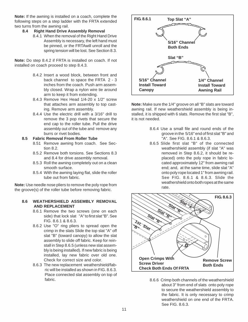
8.6 WEATHERSHIELD ASSEMBLY REMOVALAND REPLACEMENT8.6.1 Remove the two screws (one on each
side) that lock slat "A" to first slat "B". SeeFIG. 8.6.1 & 8.6.3.
8.6.2 Use "O" ring pliers to spread open thecrimp in the slats Slide the top slat "A" offslat "B" (toward canopy) to allow the slatassembly to slide off fabric. Keep for rein-stall in Step 8.6.5 (unless new slat assem-bly is being installed). If new fabric is beinginstalled, lay new fabric over old one.Check for correct size and color.
8.6.3 The new replacement weathershield/fab-ric will be installed as shown in FIG. 8.6.3.Place connected slat assembly on top offabric.
Note: Make sure the 1/4" groove on all “B” slats are towardawning rail. If new weathershield assembly is being in-stalled, it is shipped with 6 slats. Remove the first slat "B",it is not needed.
8.6.4 Use a small file and round ends of thegroove in the 5/16" end of first slat "B" and"A". See FIG. 8.6.1 & 8.6.3.
8.6.5 Slide first slat "B" of the connectedweathershield assembly (if slat "A" wasremoved in Step 8.6.2, it should be re-placed) onto the poly rope in fabric lo-cated approximately 12" from awning railend; and, at the same time, slide slat "A"onto poly rope located 1" from awning rail.See FIG. 8.6.1 & 8.6.3. Slide theweathershield onto both ropes at the samerate.
8.6.6 Crimp both channels of the weathershieldabout 3" from end of slats onto poly ropeto secure the weathershield assembly tothe fabric. It is only necessary to crimpweathershield on one end of the FRTA.See FIG. 8.6.3.
1/4” ChannelInstall TowardAwning Rail
FIG. 8.6.1 Top Slat “A”
5/16” ChannelBoth Ends
Slat “B”
5/16” ChannelInstall TowardCanopy
FIG. 8.6.3
1st. Slat“B”
Slat “B”Slat “B”Slat “B”
Slat “A”
Open Crimps WithScrew DriverCheck Both Ends Of FRTA

12
8.7 Re-Install Fabric On Roller Tube8.7.1 Unfold the new fabric and lay it on top of
the existing fabric in the exact sameposition. Be sure the new fabric is thecorrect size and color. If roller tube is beingreplaced, make sure it is the correct lengthand position it with the notch located asshown in FIG. 8.7.1.
8.7.2 Dometic requires the use of the end capguide to prevent damage to the fabric,when replacing the fabric/roller tube. Placethe end cap guide (supplied with the re-placement fabric/roller tube) on the end ofthe roller tube. The locating tab on the endcap guide is placed in the open (unused)channel of the roller tube. See FIG. 8.7.1.
Note: When changing the fabric, it is vital that the samegroove(s) be used. This eliminates the need to drill anyholes. On a new roller tube, the fabric rope is placed in thechannel with the notch in its’ edge (opposite the notch in theroller tube). See FIG. 8.7.1.
8.7.3 Guide the roller tube over the poly rope(s)of the fabric. Be careful not to damage theroller tube or the fabric.
8.7.4 Center the fabric on the roller tube andhand-roll the entire assembly in the samedirection as the original fabric.
8.7.5 See Section 8.6 for weathershield replace-ment Steps 8.6.3 to 8.6.6. and Section8.8, Replacing torsion assemblies.
8.8 Torsion Assembly Replacement8.8.1 The poly ropes must be properly trimmed
and secured to the roller tube; as it caninterfere with the torsion and allow shiftingof the fabric.
8.8.2 Use pliers to pull the fabric rope toward thecenter of the roller tube and push it back tolock it in the notch on the edge of thechannel. Cut fabric rope 1" below channel.See FIG. 8.8.2.
FIG. 8.8.2
Stretch Fabric RopeAnd Lock In Notch.Trim To 1"
Trim ValanceRope Even WithTube
View Shows RightEnd Of Roller Tube
8.8.3 Trim valance rope even with the edge ofroller tube. See FIG. 8.8.2.
8.8.4 Install left hand torsiona. Slide left hand torsion assembly into
left end of roller tube. Turn end cap tilllocating tabs are in place in the notchon the roller tube. This should alignthe open channel with the slot in theend cap.
b. Secure the end cap to the roller tubeusing three (3/6" x 3/8") pop rivets.See Section 8.9; winding left handtorsion.
8.8.5 Install right hand drive torsiona. New right hand drive torsions are
shipped with the top casting and thestabilizer positioned for installation. Ifthe torsion has been pre-installed itmust be aligned before it is put into theFRTA.
b. Apply DC power directly to the driveassembly with the emergency har-ness or the control box. Allow thestabilizer to turn until one of the stabi-lizer slots is centered on the round slotin the motor casting. See FIG. 8.8.5.
FIG. 8.8.5
Center Round SlotIn Motor Casting WithOne Of The Slots OnThe Stablizer
Motor Slot MustGo Under FabricRope ChannelOf Roller Tube Motor
Stablizer
FIG. 8.7.1 RollerTube
End Cap Guide
Place End Cap GuideOn End Of Roller Tube
Slide Fabric andValance RopesThrough Guide
ValanceRopeChannel Open
ChannelNotch
Fabric RopeChannel

13
c. When motor drive assembly is prop-erly aligned as indicated in step 8.8.5b,it is placed in the roller tube with themotor slot positioned under the chan-nel with the fabric rope.See FIG. 8.8.2.
d. Turn the end cap on the motor drivetorsion until the rivet hole match theholes in the roller tube. Install thethree 3/16" x 3/8" pop rivets to securethe torsion to the roller tube.
Note: FRTA’s installed on the coach will require the motordrive torsion assembly to be operated till the top casting willslip easily into the arm assembly. This will align the topcasting of the motor drive to the left hand top castings. Theleft and right arms must be parrallel to each other.
8.9 Left Hand Torsion Assembly Winding
Use extreme care. Springs under tension aredangerous. If not controlled they will unwindquickly. Keep hands and clothing clear of topcasting, as personal injury may result.
NOTE: If the awning is installed on a coach, complete thefollowing steps on a step ladder with the FRTA extendedtwo turns from the awning rail.
Severe injury can result from the rapid spin-ofof the top casting. NEVER use bare hands tohandle a top casting under spring tension.
8.9.1 Clamp the Vise Grip® tightly to the topcasting on the left hand torsion assembly.See FIG. 8.9.2.
8.9.2 Start with the Vise Grip® in the 6 o-clockpostion.Keep a firm hold on the ViseGrip®. Slowly wind in the direction of thearrow 9 complete turns. See FIG. 8.9.2.
Note: If Awning is fully extended; wind the spring tensiona total of 17 turns.
Left HandTorsion Shown
FIG. 8.9.2
Clamp Vise Grip®Firmly To Top Casting
Top CastingPull Cotter Pin
End Cap
Wind In Direction Of Arrow
FIG. 8.9.3
Turn Top Casting To Align SlotsIn End Cap With Pin
Pin
Slots InEnd Cap
Cotter PinInsert Cotter Pin All TheWay Through End CapAnd Hole In Torsion Rod
Left Hand Torsion Shown
8.9.3 Turn top casting or FRTA until the pin isparallel with the two slots in the end cap.See FIG. 8.9.3. Insert a 7/64" x 2-3/4" cot-ter pin through the end cap and torsionrod. Put a piece of tape over the head ofthe cotter pin to prevent it from droppingout. See FIG. 8.9.3.
8.9.4 Remove Vise Grip® from top casting andinsert into arm assembly. Replace HexHead 1/4"-20 x 1/2" screw and tighten.
Note: If awning is not installed on coach. Install per theWeatherPro installation instructions.
8.9.5 Remove 2-3/4" cotter pin and check op-eration of the awning.

14
FIG. 9.1
EXTEND
RETRACT
12 Gauge12 VDCSupply
Red
Black
RemoteSwitch
MainArm- AwningRight Side
AwningControl
EXTEND
RETRACT
Pig Tail toIgnitionIsolator
Pig Tail toControl BoxEnd
Pig Tail toRemote Switch
Pig Tailfor Motor
For OasisElite Awning
Only
Flat Four ConductorCable to Wind Sensor(18 Foot Maximum)
FUSE INSIDE
Wind Sensor SwitchENABLE (ON)DISABLE (OFF)
BlackRed
RedBlack
Green
BrownYellow
Brown/White
Green/ White
Red/WhiteBlue
Yellow/White
Pink
Black 12VDC -
GreenYellow
Brown
Red 12VDC +
Section 9 Wiring Diagram9.1 Wiring Diagram