Embed Size (px)
Citation preview
8/13/2015 2007 Ford F650 Chassis Electrical > Instrumentation & Warning Systems > Instrumentation and Warning Chimes > DIAGNOSIS AND TESTING
http://content.chiltonsonline.com/(S(li3lz1j1iaauis45tacnyk45)F(vBAdo63Q7FYPSQUeJlLaoWp3F1VWg4YGBw7qpq_Tw0Ku_Vetb1hp4FEvvc8b_NdEvHcrI0… 1/72
2007 Ford F650 : Chassis Electrical > Instrumentation & Warning Systems > Instrumentation and Warning Chimes >DIAGNOSIS AND TESTING
DIAGNOSIS AND TESTING
SECTION 41301: Instrumentation and Warning Chimes
2007 FSuper Duty 650750 Workshop Manual
DIAGNOSIS AND TESTING
Procedure revision date: 10/09/2009
INSTRUMENTATION AND WARNING CHIMESRefer to Wiring Diagrams Cell 59 , Multifunction Control Modules for schematic and connector information.
Refer to Wiring Diagrams Cell 60 , Instrument Cluster for schematic and connector information.
Special Tool(s)
Vehicle Communication Module (VCM) and Integrated Diagnostic System (IDS)software with appropriate hardware, or equivalent scan tool
IC4COM (418D553A) and MD Truck
software with appropriate hardware
73 III Automotive Meter
105R0057 or Equivalent
Listen
8/13/2015 2007 Ford F650 Chassis Electrical > Instrumentation & Warning Systems > Instrumentation and Warning Chimes > DIAGNOSIS AND TESTING
http://content.chiltonsonline.com/(S(li3lz1j1iaauis45tacnyk45)F(vBAdo63Q7FYPSQUeJlLaoWp3F1VWg4YGBw7qpq_Tw0Ku_Vetb1hp4FEvvc8b_NdEvHcrI0… 2/72
AntiLock Brake Adapter
418063 (T97P50ALA)
Instrument Gauge System Tester
014R1063 or Equivalent
Flex Probe Kit
105R025C or equivalent
Principles of Operation
Instrument Cluster (IC)Instrument Cluster (IC) ProveOutThe instrument cluster (IC) carries out a display prove out to verify that all warning/indicator lamps and monitored systems arefunctioning correctly. When the ignition switch is in the ON position with the engine off, the following indicators will illuminate:
SERVICE ENGINE SOON warning indicator
Charge system warning indicator
Red brake warning indicator
Amber brakeEmotor (hydraulic brake)
WATER IN FUEL indicator
WAIT TO START indicator
ENGINE PROTECT indicator
STOP ENGINE indicator
Antilock brake system (ABS) warning indicator (if so equipped)
CHECK TRANS indicator
Gauge Indication SystemsThe gauge indication systems use magnetic gauges mounted in the instrument cluster (IC). No adjustment, calibration ormaintenance is required for any gauges. The gauges cannot be installed separately.
Fuel Gauge UnitThe fuel sending unit is a variable resistor controlled by the action of a tube and float. When the fuel level is low, resistance inthe unit is low. When the fuel level is high, the resistance is high.
8/13/2015 2007 Ford F650 Chassis Electrical > Instrumentation & Warning Systems > Instrumentation and Warning Chimes > DIAGNOSIS AND TESTING
http://content.chiltonsonline.com/(S(li3lz1j1iaauis45tacnyk45)F(vBAdo63Q7FYPSQUeJlLaoWp3F1VWg4YGBw7qpq_Tw0Ku_Vetb1hp4FEvvc8b_NdEvHcrI0… 3/72
Water Temperature Indicator Sender UnitWhen the engine temperature is low, the resistance of the water temperature indicator sender unit is high, thus restricting theflow of current through the gauge and moving the pointer only a short distance. As the temperature of the coolant increases,the resistance decreases, allowing more current to flow through the gauge and resulting in a corresponding movement of thepointer.
Oil Pressure Indicator Sender UnitThe oil pressure indicator sender unit consists of a diaphragm and contact points. The contact points are closed with oilpressure causing the gauge to indicate NORMAL oil pressure. With no oil pressure, the contacts open and the gauge indicateslow oil pressure.
Charge Indicator SystemThe battery voltage gauge measures the voltage potential at the battery.
SpeedometerThe electronic speedometer receives a speed signal from the GEM module (if equipped with 4 wheel antilock brake system[ABS]) or the GEM/CTM (if equipped with rear wheel ABS).
OdometerA millionmile tamperresistant odometer is standard. New speedometers have a resettable odometer.
NOTE: Some state laws require that the odometer in any new speedometer must register the same as on the removedodometer. New speedometers and odometer modules with the mileage preset are available through Ford electronic repaircenters.
If the actual vehicle mileage cannot be determined, the repair centers are able to supply odometers set to "0" miles. Anodometer mileage sticker is supplied with the new odometer. This sticker must display the estimated vehicle mileage and beaffixed to the driver door jamb.
Trip OdometerThe trip odometer indicates how many miles the vehicle has been driven since the last reset.
TachometerThe tachometer is a 4500rpm tachometer. Diesel vehicles receive the tachometer signal from the engine control module(ECM).
Warning Indicators — Brake SystemAll vehicles use a brake system warning indicator in the instrument panel to warn of system malfunctions. The red brakewarning light (BRAKE) is used to indicate a low fluid level, brake malfunction or a parking brake that is not fully released. Thebrake fluid level switch is located in the brake fluid reservoir.
The yellow ABS warning indicator is used to indicate a malfunction or deactivation of the ABS. It illuminates when triggered bythe ABS control module and stays illuminated as long as the malfunction remains in the system.
Service Engine Soon Warning IndicatorThe SERVICE ENGINE SOON warning indicator is illuminated when a diagnostic trouble code (DTC) is sensed in the closedloop by the powertrain control module (PCM).
WaterInFuelThe waterinfuel indicator will be illuminated when the fuel system water collector is full.
Stop EngineThe stop engine warning indicator will be illuminated when a critical engine control system parameter is out of range.
Engine ProtectThe engine protect warning indicator (Cummins only) will be illuminated when one of the following engine fluid parameters isout of range:
Coolant level low
Oil pressure low
Coolant temperature high
Intake manifold temperature high
Check TransThe Allison electronic automatic transmission ECU activates a CHECK TRANS warning indicator lamp to alert the operator
8/13/2015 2007 Ford F650 Chassis Electrical > Instrumentation & Warning Systems > Instrumentation and Warning Chimes > DIAGNOSIS AND TESTING
http://content.chiltonsonline.com/(S(li3lz1j1iaauis45tacnyk45)F(vBAdo63Q7FYPSQUeJlLaoWp3F1VWg4YGBw7qpq_Tw0Ku_Vetb1hp4FEvvc8b_NdEvHcrI0… 4/72
that a problem has been detected. When a problem has been detected, downshifts and upshifts can be restricted.
WaitToStartThe WAITTOSTART warning indicator illuminates to advise the operator to wait until the light goes out before attempting tostart the vehicle.
High BeamThis indicator is illuminated when the high beams are on.
Warning ChimesGeneric Electronic Module (GEM)The following distinct chime rates are used to indicate warning:
Keyinignition warning is 2 chimes per second
Headlampon warning is 4 chimes per second
Door ajar warning is a single chime
Low air warning is a single chime
HydroMax® warning is one chime per second
Door Ajar Warning ChimeThe door ajar warning chime sounds when all of the following conditions are met:
Any door is ajar
The ignition switch is in the RUN position
KeyInIgnition Warning ChimeThe keyinignition chime sounds when all of the following conditions are met:
Driver door is ajar
Ignition switch is in the OFF/LOCK or ACC position
Key is in the ignition
The keyinignition warning chime will stop sounding when any one of the conditions above are removed.
HydroMax® Warning ChimeThe HydroMax® warning chime sounds when any one of the following conditions exist:
The brake pedal is pressed and the vehicle is not running
The HydroMax® flow switch closes with the ignition in the RUNposition
The GEM does not see a change in the state of the flow switch(closed or open) once the vehicle has been started
The GEM provides output to the HydroMax® relay to activate theHydroMax® motor, but 12volt feedback is not provided to the GEM,confirming HydroMax® operation
A 12volt feedback is provided to the GEM, but the GEM did notrequest HydroMax® motor operation
Headlamps Warning ChimeThe headlamps warning chime sounds when all of the following conditions are met:
The driver door is ajar
The headlamp switch is in the park or head position
The ignition switch state is in the OFF/LOCK position
Key is out of ignition
The headlamps warning chime will stop sounding when any one of the conditions above are removed.
8/13/2015 2007 Ford F650 Chassis Electrical > Instrumentation & Warning Systems > Instrumentation and Warning Chimes > DIAGNOSIS AND TESTING
http://content.chiltonsonline.com/(S(li3lz1j1iaauis45tacnyk45)F(vBAdo63Q7FYPSQUeJlLaoWp3F1VWg4YGBw7qpq_Tw0Ku_Vetb1hp4FEvvc8b_NdEvHcrI0… 5/72
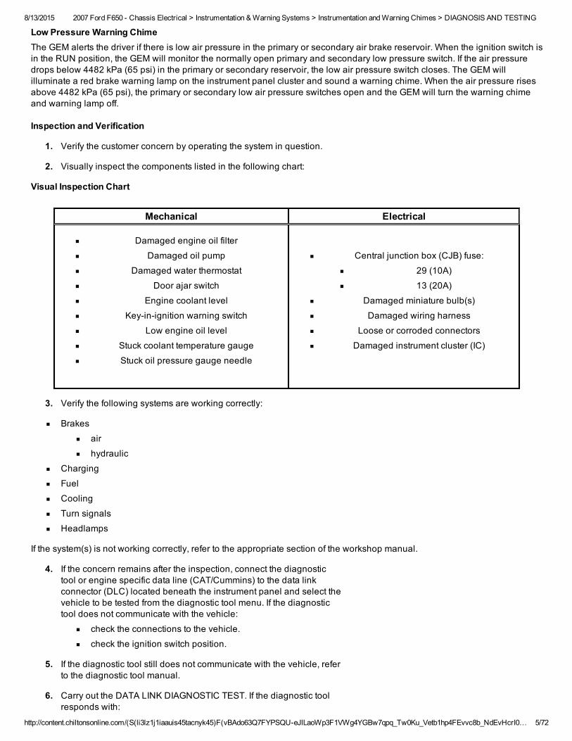
Low Pressure Warning ChimeThe GEM alerts the driver if there is low air pressure in the primary or secondary air brake reservoir. When the ignition switch isin the RUN position, the GEM will monitor the normally open primary and secondary low pressure switch. If the air pressuredrops below 4482 kPa (65 psi) in the primary or secondary reservoir, the low air pressure switch closes. The GEM willilluminate a red brake warning lamp on the instrument panel cluster and sound a warning chime. When the air pressure risesabove 4482 kPa (65 psi), the primary or secondary low air pressure switches open and the GEM will turn the warning chimeand warning lamp off.
Inspection and Verification
1. Verify the customer concern by operating the system in question.
2. Visually inspect the components listed in the following chart:
Visual Inspection Chart
Mechanical Electrical
Damaged engine oil filter
Damaged oil pump
Damaged water thermostat
Door ajar switch
Engine coolant level
Keyinignition warning switch
Low engine oil level
Stuck coolant temperature gauge
Stuck oil pressure gauge needle
Central junction box (CJB) fuse:
29 (10A)
13 (20A)
Damaged miniature bulb(s)
Damaged wiring harness
Loose or corroded connectors
Damaged instrument cluster (IC)
3. Verify the following systems are working correctly:
Brakes
air
hydraulic
Charging
Fuel
Cooling
Turn signals
Headlamps
If the system(s) is not working correctly, refer to the appropriate section of the workshop manual.
4. If the concern remains after the inspection, connect the diagnostictool or engine specific data line (CAT/Cummins) to the data linkconnector (DLC) located beneath the instrument panel and select thevehicle to be tested from the diagnostic tool menu. If the diagnostictool does not communicate with the vehicle:
check the connections to the vehicle.
check the ignition switch position.
5. If the diagnostic tool still does not communicate with the vehicle, referto the diagnostic tool manual.
6. Carry out the DATA LINK DIAGNOSTIC TEST. If the diagnostic toolresponds with:
8/13/2015 2007 Ford F650 Chassis Electrical > Instrumentation & Warning Systems > Instrumentation and Warning Chimes > DIAGNOSIS AND TESTING
http://content.chiltonsonline.com/(S(li3lz1j1iaauis45tacnyk45)F(vBAdo63Q7FYPSQUeJlLaoWp3F1VWg4YGBw7qpq_Tw0Ku_Vetb1hp4FEvvc8b_NdEvHcrI0… 6/72
SCP+, SCP or UBP circuits fault = ALL ECUS NO RESP/NOTEQUIP, refer to Module Communications Network.NO RESP/NOT EQUIP for generic electronic module (GEM),GO to Pinpoint Test A.NOTE: The following criteria must be met when carrying outthe GEM OnDemand SelfTest: headlamps and parklampsmust be on. Failure to meet this criteria will result in DTCB1575 being set.
SYSTEM PASSED, retrieve and record the continuousdiagnostic trouble codes (DTCs), erase the continuous DTCsand carry out selftest diagnostics for the GEM.
7. If the DTCs retrieved are related to the concern, go to the GEMDiagnostic Trouble Code (DTC) Index to continue diagnostics.
8. If no DTCs related to the concern are retrieved, GO to SymptomChart Instrument Cluster (IC) or GO to Symptom Chart WarningChimes.
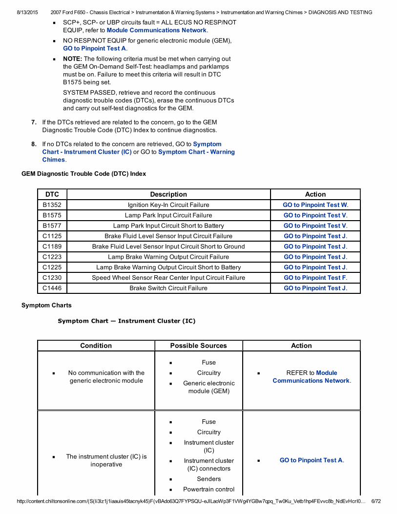
GEM Diagnostic Trouble Code (DTC) Index
DTC Description ActionB1352 Ignition KeyIn Circuit Failure GO to Pinpoint Test W.
B1575 Lamp Park Input Circuit Failure GO to Pinpoint Test V.B1577 Lamp Park Input Circuit Short to Battery GO to Pinpoint Test V.C1125 Brake Fluid Level Sensor Input Circuit Failure GO to Pinpoint Test J.C1189 Brake Fluid Level Sensor Input Circuit Short to Ground GO to Pinpoint Test J.C1223 Lamp Brake Warning Output Circuit Failure GO to Pinpoint Test J.C1225 Lamp Brake Warning Output Circuit Short to Battery GO to Pinpoint Test J.C1230 Speed Wheel Sensor Rear Center Input Circuit Failure GO to Pinpoint Test F.C1446 Brake Switch Circuit Failure GO to Pinpoint Test J.
Symptom Charts
Symptom Chart — Instrument Cluster (IC)
Condition Possible Sources Action
No communication with thegeneric electronic module
Fuse
Circuitry
Generic electronicmodule (GEM)
REFER to ModuleCommunications Network.
The instrument cluster (IC) isinoperative
Fuse
Circuitry
Instrument cluster(IC)
Instrument cluster(IC) connectors
Senders
Powertrain control
GO to Pinpoint Test A.
8/13/2015 2007 Ford F650 Chassis Electrical > Instrumentation & Warning Systems > Instrumentation and Warning Chimes > DIAGNOSIS AND TESTING
http://content.chiltonsonline.com/(S(li3lz1j1iaauis45tacnyk45)F(vBAdo63Q7FYPSQUeJlLaoWp3F1VWg4YGBw7qpq_Tw0Ku_Vetb1hp4FEvvc8b_NdEvHcrI0… 7/72
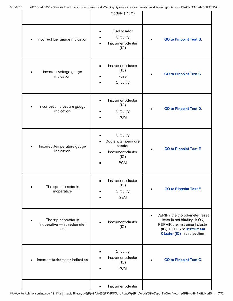
module (PCM)
Incorrect fuel gauge indication
Fuel sender
Circuitry
Instrument cluster(IC)
GO to Pinpoint Test B.
Incorrect voltage gaugeindication
Instrument cluster(IC)
Fuse
Circuitry
GO to Pinpoint Test C.
Incorrect oil pressure gaugeindication
Instrument cluster(IC)
Circuitry
PCM
GO to Pinpoint Test D.
Incorrect temperature gaugeindication
Circuitry
Coolant temperaturesender
Instrument cluster(IC)
PCM
GO to Pinpoint Test E.
The speedometer isinoperative
Instrument cluster(IC)
Circuitry
GEM
GO to Pinpoint Test F.
The trip odometer isinoperative — speedometer
OK
Instrument cluster(IC)
VERIFY the trip odometer resetlever is not binding. If OK,
REPAIR the instrument cluster(IC). REFER to InstrumentCluster (IC) in this section.
Incorrect tachometer indication
Circuitry
Instrument cluster(IC)
PCM
GO to Pinpoint Test G.
Instrument cluster
8/13/2015 2007 Ford F650 Chassis Electrical > Instrumentation & Warning Systems > Instrumentation and Warning Chimes > DIAGNOSIS AND TESTING
http://content.chiltonsonline.com/(S(li3lz1j1iaauis45tacnyk45)F(vBAdo63Q7FYPSQUeJlLaoWp3F1VWg4YGBw7qpq_Tw0Ku_Vetb1hp4FEvvc8b_NdEvHcrI0… 8/72
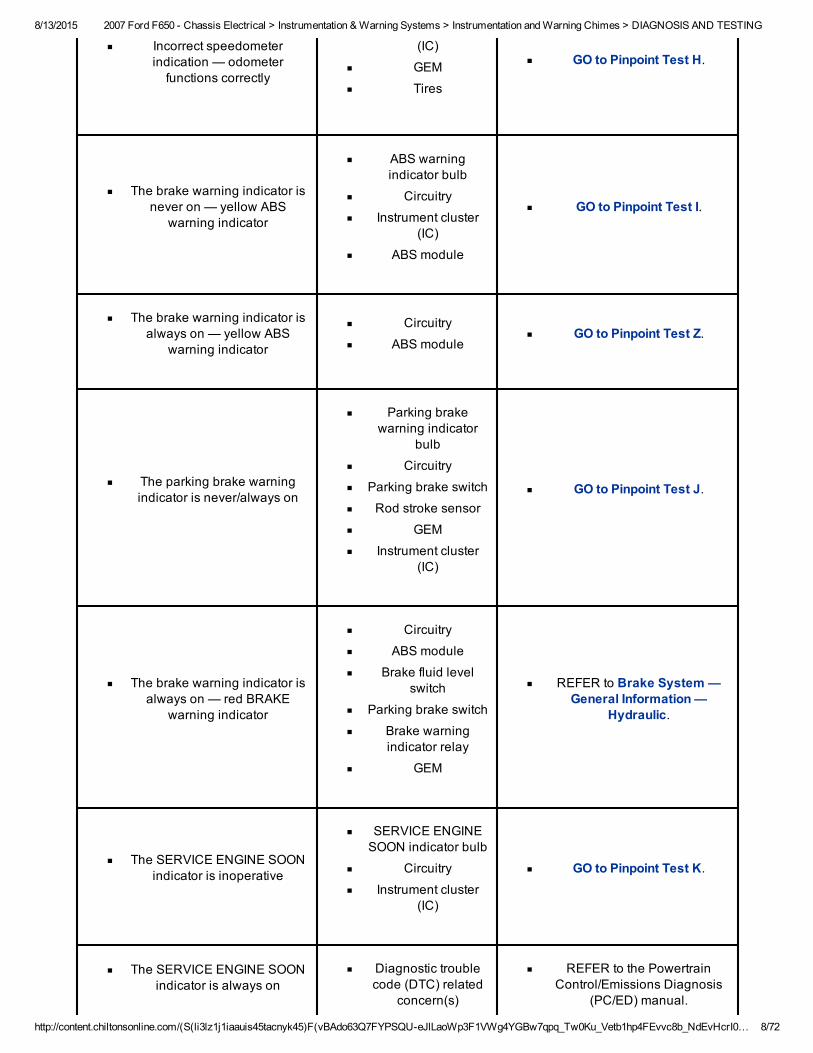
Incorrect speedometerindication — odometerfunctions correctly
(IC)
GEM
Tires
GO to Pinpoint Test H.
The brake warning indicator isnever on — yellow ABS
warning indicator
ABS warningindicator bulb
Circuitry
Instrument cluster(IC)
ABS module
GO to Pinpoint Test I.
The brake warning indicator isalways on — yellow ABS
warning indicator
Circuitry
ABS module
GO to Pinpoint Test Z.
The parking brake warningindicator is never/always on
Parking brakewarning indicator
bulb
Circuitry
Parking brake switch
Rod stroke sensor
GEM
Instrument cluster(IC)
GO to Pinpoint Test J.
The brake warning indicator isalways on — red BRAKE
warning indicator
Circuitry
ABS module
Brake fluid levelswitch
Parking brake switch
Brake warningindicator relay
GEM
REFER to Brake System —General Information —
Hydraulic.
The SERVICE ENGINE SOONindicator is inoperative
SERVICE ENGINESOON indicator bulb
Circuitry
Instrument cluster(IC)
GO to Pinpoint Test K.
The SERVICE ENGINE SOONindicator is always on
Diagnostic troublecode (DTC) related
concern(s)
REFER to the PowertrainControl/Emissions Diagnosis
(PC/ED) manual.
8/13/2015 2007 Ford F650 Chassis Electrical > Instrumentation & Warning Systems > Instrumentation and Warning Chimes > DIAGNOSIS AND TESTING
http://content.chiltonsonline.com/(S(li3lz1j1iaauis45tacnyk45)F(vBAdo63Q7FYPSQUeJlLaoWp3F1VWg4YGBw7qpq_Tw0Ku_Vetb1hp4FEvvc8b_NdEvHcrI0… 9/72
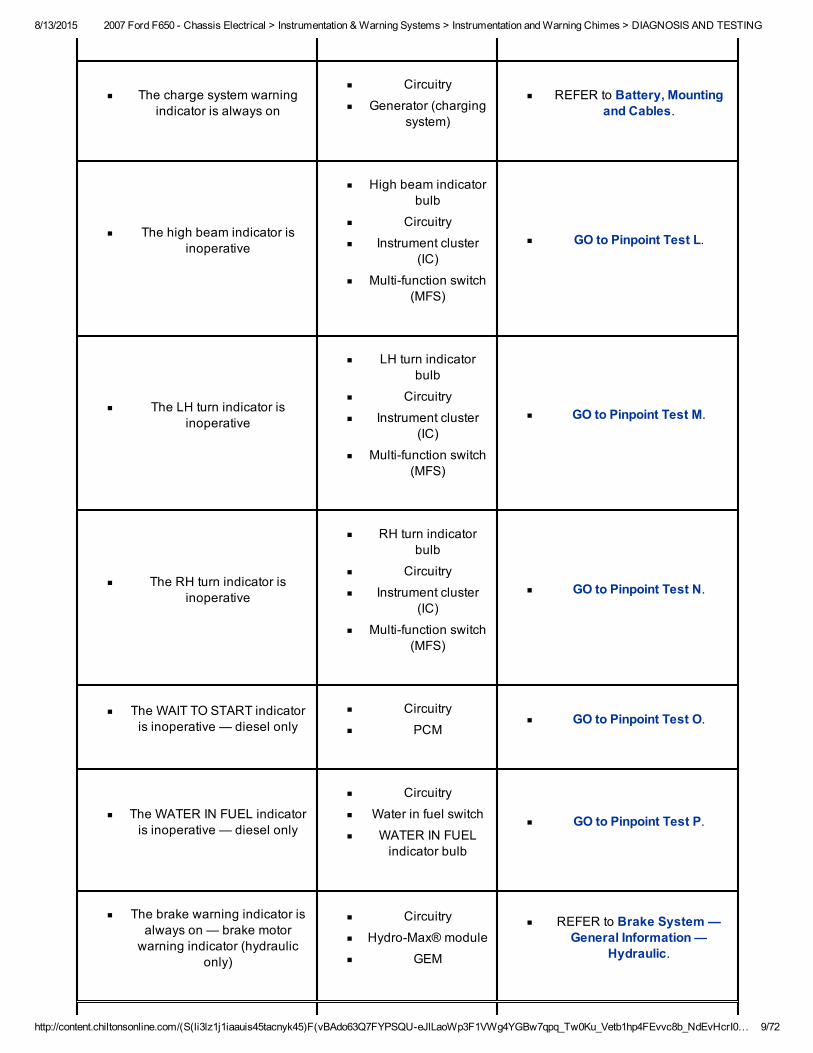
The charge system warningindicator is always on
Circuitry
Generator (chargingsystem)
REFER to Battery, Mountingand Cables.
The high beam indicator isinoperative
High beam indicatorbulb
Circuitry
Instrument cluster(IC)
Multifunction switch(MFS)
GO to Pinpoint Test L.
The LH turn indicator isinoperative
LH turn indicatorbulb
Circuitry
Instrument cluster(IC)
Multifunction switch(MFS)
GO to Pinpoint Test M.
The RH turn indicator isinoperative
RH turn indicatorbulb
Circuitry
Instrument cluster(IC)
Multifunction switch(MFS)
GO to Pinpoint Test N.
The WAIT TO START indicatoris inoperative — diesel only
Circuitry
PCM
GO to Pinpoint Test O.
The WATER IN FUEL indicatoris inoperative — diesel only
Circuitry
Water in fuel switch
WATER IN FUELindicator bulb
GO to Pinpoint Test P.
The brake warning indicator isalways on — brake motorwarning indicator (hydraulic
only)
Circuitry
HydroMax® module
GEM
REFER to Brake System —General Information —
Hydraulic.
8/13/2015 2007 Ford F650 Chassis Electrical > Instrumentation & Warning Systems > Instrumentation and Warning Chimes > DIAGNOSIS AND TESTING
http://content.chiltonsonline.com/(S(li3lz1j1iaauis45tacnyk45)F(vBAdo63Q7FYPSQUeJlLaoWp3F1VWg4YGBw7qpq_Tw0Ku_Vetb1hp4FEvvc8b_NdEvHcrI… 10/72
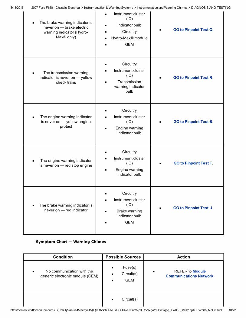
The brake warning indicator isnever on — brake electricwarning indicator (Hydro
Max® only)
Instrument cluster(IC)
Indicator bulb
Circuitry
HydroMax® module
GEM
GO to Pinpoint Test Q.
The transmission warningindicator is never on — yellow
check trans
Circuitry
Instrument cluster(IC)
Transmissionwarning indicator
bulb
GO to Pinpoint Test R.
The engine warning indicatoris never on — yellow engine
protect
Circuitry
Instrument cluster(IC)
Engine warningindicator bulb
GO to Pinpoint Test S.
The engine warning indicatoris never on — red stop engine
Circuitry
Instrument cluster(IC)
Engine warningindicator bulb
GO to Pinpoint Test T.
The brake warning indicator isnever on — red indicator
Circuitry
Instrument cluster(IC)
Brake warningindicator bulb
GEM
GO to Pinpoint Test U.
Symptom Chart — Warning Chimes
Condition Possible Sources Action
No communication with thegeneric electronic module (GEM)
Fuse(s)
Circuit(s)
GEM
REFER to ModuleCommunications Network.
Circuit(s)
8/13/2015 2007 Ford F650 Chassis Electrical > Instrumentation & Warning Systems > Instrumentation and Warning Chimes > DIAGNOSIS AND TESTING
http://content.chiltonsonline.com/(S(li3lz1j1iaauis45tacnyk45)F(vBAdo63Q7FYPSQUeJlLaoWp3F1VWg4YGBw7qpq_Tw0Ku_Vetb1hp4FEvvc8b_NdEvHcrI… 11/72
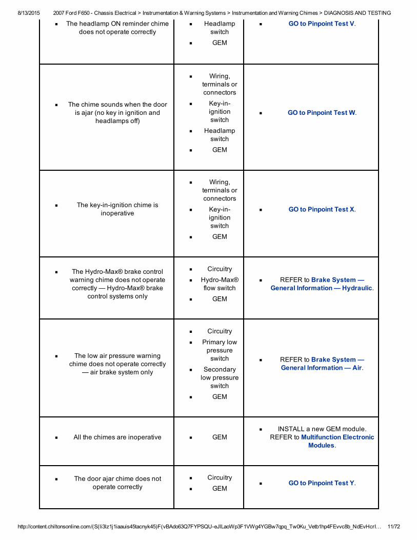
The headlamp ON reminder chimedoes not operate correctly
Headlampswitch
GEM
GO to Pinpoint Test V.
The chime sounds when the dooris ajar (no key in ignition and
headlamps off)
Wiring,terminals orconnectors
Keyinignitionswitch
Headlampswitch
GEM
GO to Pinpoint Test W.
The keyinignition chime isinoperative
Wiring,terminals orconnectors
Keyinignitionswitch
GEM
GO to Pinpoint Test X.
The HydroMax® brake controlwarning chime does not operatecorrectly — HydroMax® brake
control systems only
Circuitry
HydroMax®flow switch
GEM
REFER to Brake System —General Information — Hydraulic.
The low air pressure warningchime does not operate correctly
— air brake system only
Circuitry
Primary lowpressureswitch
Secondarylow pressure
switch
GEM
REFER to Brake System —General Information — Air.
All the chimes are inoperative
GEM
INSTALL a new GEM module.REFER to Multifunction Electronic
Modules.
The door ajar chime does notoperate correctly
Circuitry
GEM
GO to Pinpoint Test Y.
8/13/2015 2007 Ford F650 Chassis Electrical > Instrumentation & Warning Systems > Instrumentation and Warning Chimes > DIAGNOSIS AND TESTING
http://content.chiltonsonline.com/(S(li3lz1j1iaauis45tacnyk45)F(vBAdo63Q7FYPSQUeJlLaoWp3F1VWg4YGBw7qpq_Tw0Ku_Vetb1hp4FEvvc8b_NdEvHcrI… 12/72
Pinpoint Tests
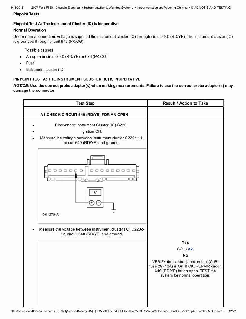
Pinpoint Test A: The Instrument Cluster (IC) Is InoperativeNormal OperationUnder normal operation, voltage is supplied the instrument cluster (IC) through circuit 640 (RD/YE). The instrument cluster (IC)is grounded through circuit 676 (PK/OG).
Possible causes
An open in circuit 640 (RD/YE) or 676 (PK/OG)
Fuse
Instrument cluster (IC)
PINPOINT TEST A: THE INSTRUMENT CLUSTER (IC) IS INOPERATIVENOTICE: Use the correct probe adapter(s) when making measurements. Failure to use the correct probe adapter(s) maydamage the connector.
Test Step Result / Action to Take
A1 CHECK CIRCUIT 640 (RD/YE) FOR AN OPEN
Disconnect: Instrument Cluster (IC) C220 .
Ignition ON.
Measure the voltage between instrument cluster C220b11,circuit 640 (RD/YE) and ground.
Measure the voltage between instrument cluster (IC) C220c12, circuit 640 (RD/YE) and ground.
YesGO to A2.
NoVERIFY the central junction box (CJB)
fuse 29 (10A) is OK. If OK, REPAIR circuit640 (RD/YE) for an open. TEST the
system for normal operation.
8/13/2015 2007 Ford F650 Chassis Electrical > Instrumentation & Warning Systems > Instrumentation and Warning Chimes > DIAGNOSIS AND TESTING
http://content.chiltonsonline.com/(S(li3lz1j1iaauis45tacnyk45)F(vBAdo63Q7FYPSQUeJlLaoWp3F1VWg4YGBw7qpq_Tw0Ku_Vetb1hp4FEvvc8b_NdEvHcrI… 13/72
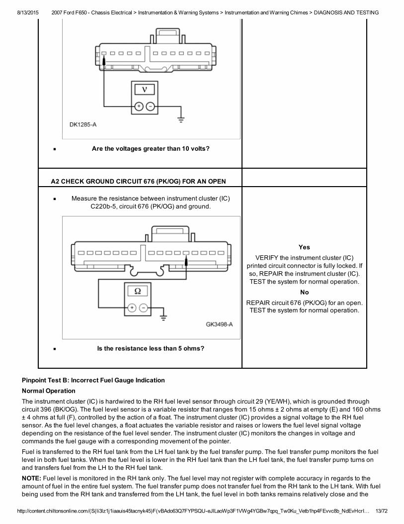
Are the voltages greater than 10 volts?
A2 CHECK GROUND CIRCUIT 676 (PK/OG) FOR AN OPEN
Measure the resistance between instrument cluster (IC)C220b5, circuit 676 (PK/OG) and ground.
Is the resistance less than 5 ohms?
YesVERIFY the instrument cluster (IC)
printed circuit connector is fully locked. Ifso, REPAIR the instrument cluster (IC).TEST the system for normal operation.
NoREPAIR circuit 676 (PK/OG) for an open.TEST the system for normal operation.
Pinpoint Test B: Incorrect Fuel Gauge IndicationNormal OperationThe instrument cluster (IC) is hardwired to the RH fuel level sensor through circuit 29 (YE/WH), which is grounded throughcircuit 396 (BK/OG). The fuel level sensor is a variable resistor that ranges from 15 ohms ± 2 ohms at empty (E) and 160 ohms± 4 ohms at full (F), controlled by the action of a float. The instrument cluster (IC) provides a signal voltage to the RH fuelsensor. As the fuel level changes, a float actuates the variable resistor and raises or lowers the fuel level signal voltagedepending on the resistance of the fuel level sender. The instrument cluster (IC) monitors the changes in voltage andcommands the fuel gauge with a corresponding movement of the pointer.
Fuel is transferred to the RH fuel tank from the LH fuel tank by the fuel transfer pump. The fuel transfer pump monitors the fuellevel in both fuel tanks. When the fuel level is lower in the RH fuel tank than the LH fuel tank, the fuel transfer pump turns onand transfers fuel from the LH to the RH fuel tank.
NOTE: Fuel level is monitored in the RH tank only. The fuel level may not register with complete accuracy in regards to theamount of fuel in the entire fuel system. The fuel transfer pump does not transfer fuel from the RH tank to the LH tank. With fuelbeing used from the RH tank and transferred from the LH tank, the fuel level in both tanks remains relatively close and the
8/13/2015 2007 Ford F650 Chassis Electrical > Instrumentation & Warning Systems > Instrumentation and Warning Chimes > DIAGNOSIS AND TESTING
http://content.chiltonsonline.com/(S(li3lz1j1iaauis45tacnyk45)F(vBAdo63Q7FYPSQUeJlLaoWp3F1VWg4YGBw7qpq_Tw0Ku_Vetb1hp4FEvvc8b_NdEvHcrI… 14/72
gauge registers the correct amount of remaining fuel in both tanks. If fuel is added to the RH fuel tank and not added to the LHfuel tank, the fuel gauge displays only the fuel level of the RH tank.
Possible causes
An open in circuit 29 (YE/WH) or 396 (BK/OG)
Instrument cluster (IC)
Fuel sender
PINPOINT TEST B: INCORRECT FUEL GAUGE INDICATIONNOTICE: Use the correct probe adapter(s) when making measurements. Failure to use the correct probe adapter(s) maydamage the connector.NOTE: This pinpoint test assumes that the fuel transfer pump is functioning correctly and fuel is transferring. Make sure toverify that the fuel transfer pump is operating and that fuel is transferring from the LH fuel tank to the RH fuel tank.
Test Step Result / Action to Take
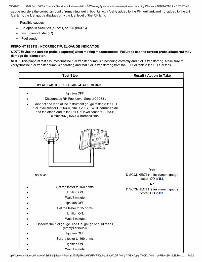
B1 CHECK THE FUEL GAUGE OPERATION
Ignition OFF.
Disconnect: RH Fuel Level SensorC3263 .
Connect one lead of the instrument gauge tester to the RHfuel level sensor C3263A, circuit 29 (YE/WH), harness sideand the other lead to the RH fuel level sensor C3263B,
circuit 396 (BK/OG), harness side.
Set the tester to 160 ohms.
Ignition ON.
Wait 1 minute.
Ignition OFF.
Set the tester to 15 ohms.
Ignition ON.
Wait 1 minute.
Observe the fuel gauge. The fuel gauge should read E(empty) or below.
Ignition OFF.
Set the tester to 160 ohms.
Ignition ON.
Wait 1 minute.
YesDISCONNECT the instrument gauge
tester. GO to B2.No
DISCONNECT the instrument gaugetester. GO to B3.
8/13/2015 2007 Ford F650 Chassis Electrical > Instrumentation & Warning Systems > Instrumentation and Warning Chimes > DIAGNOSIS AND TESTING
http://content.chiltonsonline.com/(S(li3lz1j1iaauis45tacnyk45)F(vBAdo63Q7FYPSQUeJlLaoWp3F1VWg4YGBw7qpq_Tw0Ku_Vetb1hp4FEvvc8b_NdEvHcrI… 15/72
Observe the fuel gauge. The fuel gauge should read F (full)or above.
Does the fuel gauge operate correctly?
B2 INSPECT THE FUEL TANK
Visually inspect the fuel tank for any damage or deformation.
Is the fuel tank OK?
YesINSTALL a new fuel level sensor.
REFER to Fuel Tank and Lines. TESTthe system for normal operation.
NoVERIFY that the fuel level sensor is OK.INSTALL a new fuel tank. REFER to FuelTank and Lines. TEST the system for
normal operation.
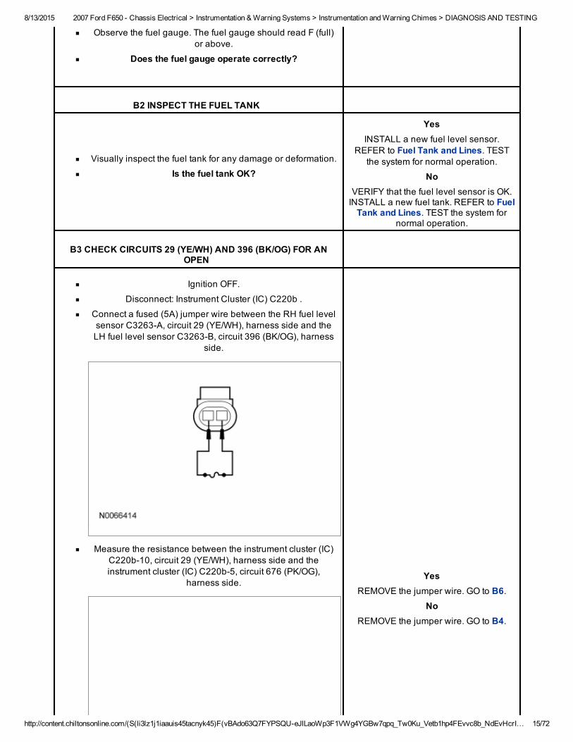
B3 CHECK CIRCUITS 29 (YE/WH) AND 396 (BK/OG) FOR ANOPEN
Ignition OFF.
Disconnect: Instrument Cluster (IC) C220b .
Connect a fused (5A) jumper wire between the RH fuel levelsensor C3263A, circuit 29 (YE/WH), harness side and theLH fuel level sensor C3263B, circuit 396 (BK/OG), harness
side.
Measure the resistance between the instrument cluster (IC)C220b10, circuit 29 (YE/WH), harness side and theinstrument cluster (IC) C220b5, circuit 676 (PK/OG),
harness side.Yes
REMOVE the jumper wire. GO to B6.No
REMOVE the jumper wire. GO to B4.
8/13/2015 2007 Ford F650 Chassis Electrical > Instrumentation & Warning Systems > Instrumentation and Warning Chimes > DIAGNOSIS AND TESTING
http://content.chiltonsonline.com/(S(li3lz1j1iaauis45tacnyk45)F(vBAdo63Q7FYPSQUeJlLaoWp3F1VWg4YGBw7qpq_Tw0Ku_Vetb1hp4FEvvc8b_NdEvHcrI… 16/72
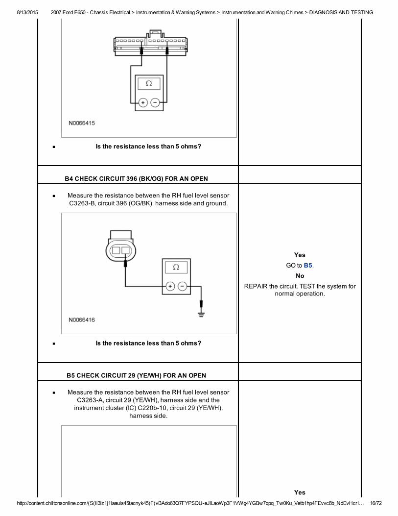
Is the resistance less than 5 ohms?
B4 CHECK CIRCUIT 396 (BK/OG) FOR AN OPEN
Measure the resistance between the RH fuel level sensorC3263B, circuit 396 (OG/BK), harness side and ground.
Is the resistance less than 5 ohms?
YesGO to B5.
NoREPAIR the circuit. TEST the system for
normal operation.
B5 CHECK CIRCUIT 29 (YE/WH) FOR AN OPEN
Measure the resistance between the RH fuel level sensorC3263A, circuit 29 (YE/WH), harness side and theinstrument cluster (IC) C220b10, circuit 29 (YE/WH),
harness side.
Yes
8/13/2015 2007 Ford F650 Chassis Electrical > Instrumentation & Warning Systems > Instrumentation and Warning Chimes > DIAGNOSIS AND TESTING
http://content.chiltonsonline.com/(S(li3lz1j1iaauis45tacnyk45)F(vBAdo63Q7FYPSQUeJlLaoWp3F1VWg4YGBw7qpq_Tw0Ku_Vetb1hp4FEvvc8b_NdEvHcrI… 17/72
Is the resistance less than 5 ohms?
GO to B6.No
REPAIR the circuit. TEST the system fornormal operation.
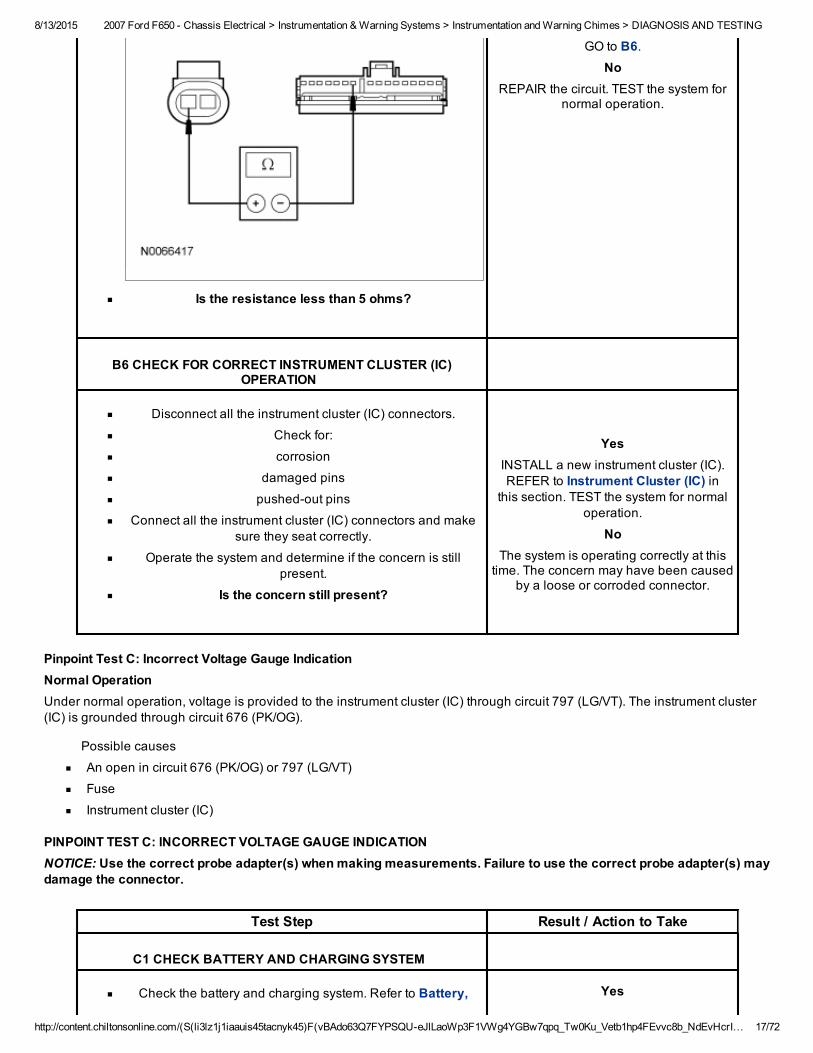
B6 CHECK FOR CORRECT INSTRUMENT CLUSTER (IC)OPERATION
Disconnect all the instrument cluster (IC) connectors.
Check for:
corrosion
damaged pins
pushedout pins
Connect all the instrument cluster (IC) connectors and makesure they seat correctly.
Operate the system and determine if the concern is stillpresent.
Is the concern still present?
YesINSTALL a new instrument cluster (IC).REFER to Instrument Cluster (IC) in
this section. TEST the system for normaloperation.
NoThe system is operating correctly at thistime. The concern may have been caused
by a loose or corroded connector.
Pinpoint Test C: Incorrect Voltage Gauge IndicationNormal OperationUnder normal operation, voltage is provided to the instrument cluster (IC) through circuit 797 (LG/VT). The instrument cluster(IC) is grounded through circuit 676 (PK/OG).
Possible causes
An open in circuit 676 (PK/OG) or 797 (LG/VT)
Fuse
Instrument cluster (IC)
PINPOINT TEST C: INCORRECT VOLTAGE GAUGE INDICATIONNOTICE: Use the correct probe adapter(s) when making measurements. Failure to use the correct probe adapter(s) maydamage the connector.
Test Step Result / Action to Take
C1 CHECK BATTERY AND CHARGING SYSTEM
Check the battery and charging system. Refer to Battery, Yes
8/13/2015 2007 Ford F650 Chassis Electrical > Instrumentation & Warning Systems > Instrumentation and Warning Chimes > DIAGNOSIS AND TESTING
http://content.chiltonsonline.com/(S(li3lz1j1iaauis45tacnyk45)F(vBAdo63Q7FYPSQUeJlLaoWp3F1VWg4YGBw7qpq_Tw0Ku_Vetb1hp4FEvvc8b_NdEvHcrI… 18/72
Mounting and Cables.Is the battery and charging system OK?
GO to C2.No
REFER to Battery, Mounting and Cables.
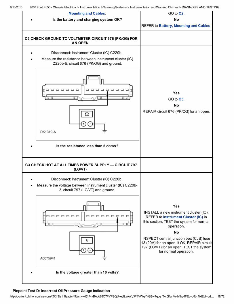
C2 CHECK GROUND TO VOLTMETER CIRCUIT 676 (PK/OG) FORAN OPEN
Disconnect: Instrument Cluster (IC) C220b .
Measure the resistance between instrument cluster (IC)C220b5, circuit 676 (PK/OG) and ground.
Is the resistance less than 5 ohms?
YesGO to C3.
NoREPAIR circuit 676 (PK/OG) for an open.
C3 CHECK HOT AT ALL TIMES POWER SUPPLY — CIRCUIT 797(LG/VT)
Disconnect: Instrument Cluster (IC) C220b .
Measure the voltage between instrument cluster (IC) C220b3, circuit 797 (LG/VT) and ground.
Is the voltage greater than 10 volts?
YesINSTALL a new instrument cluster (IC).REFER to Instrument Cluster (IC) in
this section. TEST the system for normaloperation.
NoINSPECT central junction box (CJB) fuse13 (20A) for an open. If OK, REPAIR circuit797 (LG/VT) for an open. TEST the system
for normal operation.
Pinpoint Test D: Incorrect Oil Pressure Gauge Indication
8/13/2015 2007 Ford F650 Chassis Electrical > Instrumentation & Warning Systems > Instrumentation and Warning Chimes > DIAGNOSIS AND TESTING
http://content.chiltonsonline.com/(S(li3lz1j1iaauis45tacnyk45)F(vBAdo63Q7FYPSQUeJlLaoWp3F1VWg4YGBw7qpq_Tw0Ku_Vetb1hp4FEvvc8b_NdEvHcrI… 19/72
Normal OperationUnder normal operation, when the oil pressure is normal, the oil pressure switch provides ground to the instrument cluster (IC)through circuit 31 (WH/RD).
Possible causes
An open in circuit 31 (WH/RD)
Instrument cluster (IC)
PINPOINT TEST D: INCORRECT OIL PRESSURE GAUGE INDICATIONNOTICE: Use the correct probe adapter(s) when making measurements. Failure to use the correct probe adapter(s) maydamage the connector.
Test Step Result / Action to Take
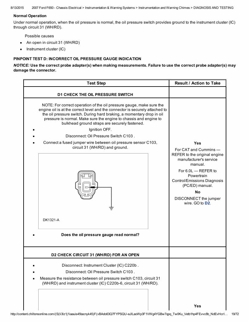
D1 CHECK THE OIL PRESSURE SWITCH
NOTE: For correct operation of the oil pressure gauge, make sure theengine oil is at the correct level and the connector is securely attached tothe oil pressure switch. During hard braking, a momentary drop in oilpressure is normal. Make sure the engine to chassis and engine to
bulkhead ground straps are securely fastened.Ignition OFF.
Disconnect: Oil Pressure Switch C103 .
Connect a fused jumper wire between oil pressure sensor C103,circuit 31 (WH/RD) and ground.
Does the oil pressure gauge read normal?
YesFor CAT and Cummins —
REFER to the original enginemanufacturer's service
manual.
For 6.0L — REFER toPowertrain
Control/Emissions Diagnosis(PC/ED) manual.
NoDISCONNECT the jumper
wire. GO to D2.
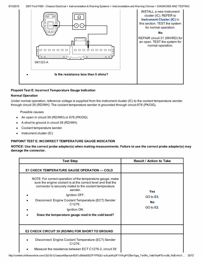
D2 CHECK CIRCUIT 31 (WH/RD) FOR AN OPEN
Disconnect: Instrument Cluster (IC) C220b .
Disconnect: Oil Pressure Switch C103 .
Measure the resistance between oil pressure switch C103, circuit 31(WH/RD) and instrument cluster (IC) C220b6, circuit 31 (WH/RD).
Yes
8/13/2015 2007 Ford F650 Chassis Electrical > Instrumentation & Warning Systems > Instrumentation and Warning Chimes > DIAGNOSIS AND TESTING
http://content.chiltonsonline.com/(S(li3lz1j1iaauis45tacnyk45)F(vBAdo63Q7FYPSQUeJlLaoWp3F1VWg4YGBw7qpq_Tw0Ku_Vetb1hp4FEvvc8b_NdEvHcrI… 20/72
Is the resistance less than 5 ohms?
INSTALL a new instrumentcluster (IC). REFER to
Instrument Cluster (IC) inthis section. TEST the system
for normal operation.
NoREPAIR circuit 31 (WH/RD) foran open. TEST the system for
normal operation.
Pinpoint Test E: Incorrect Temperature Gauge IndicationNormal OperationUnder normal operation, reference voltage is supplied from the instrument cluster (IC) to the coolant temperature senderthrough circuit 39 (RD/WH). The coolant temperature sender is grounded through circuit 676 (PK/OG).
Possible causes
An open in circuit 39 (RD/WH) or 676 (PK/OG)
A short to ground in circuit 39 (RD/WH)
Coolant temperature sender
Instrument cluster (IC)
PINPOINT TEST E: INCORRECT TEMPERATURE GAUGE INDICATIONNOTICE: Use the correct probe adapter(s) when making measurements. Failure to use the correct probe adapter(s) maydamage the connector.
Test Step Result / Action to Take
E1 CHECK TEMPERATURE GAUGE OPERATION — COLD
NOTE: For correct operation of the temperature gauge, makesure the engine coolant is at the correct level and that theconnector is securely mated to the coolant temperature
sender.Ignition OFF.
Disconnect: Engine Coolant Temperature (ECT) SenderC1276 .
Ignition ON.
Does the temperature gauge read in the cold band?
YesGO to E3.
NoGO to E2.
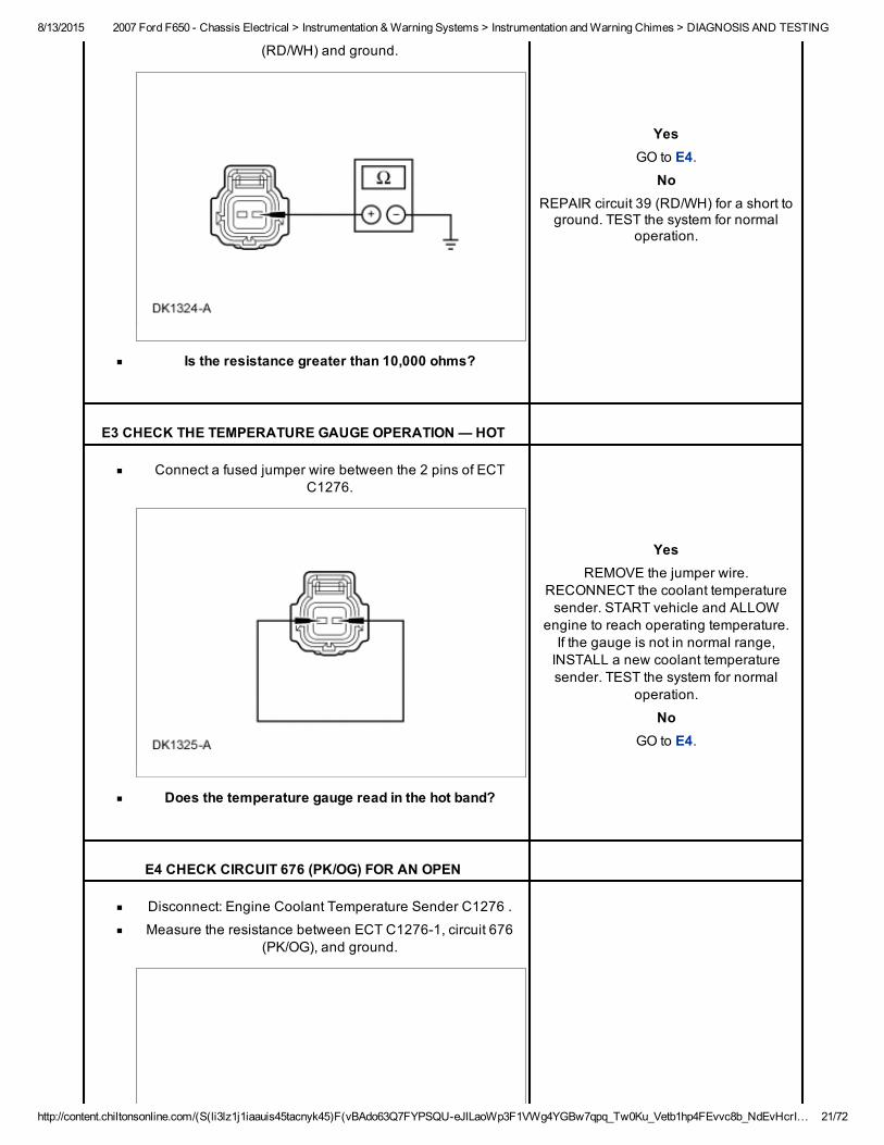
E2 CHECK CIRCUIT 39 (RD/WH) FOR SHORT TO GROUND
Disconnect: Engine Coolant Temperature (ECT) SenderC1276 .
Measure the resistance between ECT C12762, circuit 39
8/13/2015 2007 Ford F650 Chassis Electrical > Instrumentation & Warning Systems > Instrumentation and Warning Chimes > DIAGNOSIS AND TESTING
http://content.chiltonsonline.com/(S(li3lz1j1iaauis45tacnyk45)F(vBAdo63Q7FYPSQUeJlLaoWp3F1VWg4YGBw7qpq_Tw0Ku_Vetb1hp4FEvvc8b_NdEvHcrI… 21/72
(RD/WH) and ground.
Is the resistance greater than 10,000 ohms?
YesGO to E4.
NoREPAIR circuit 39 (RD/WH) for a short toground. TEST the system for normal
operation.
E3 CHECK THE TEMPERATURE GAUGE OPERATION — HOT
Connect a fused jumper wire between the 2 pins of ECTC1276.
Does the temperature gauge read in the hot band?
YesREMOVE the jumper wire.
RECONNECT the coolant temperaturesender. START vehicle and ALLOW
engine to reach operating temperature.If the gauge is not in normal range,INSTALL a new coolant temperaturesender. TEST the system for normal
operation.
NoGO to E4.
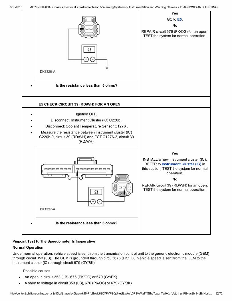
E4 CHECK CIRCUIT 676 (PK/OG) FOR AN OPEN
Disconnect: Engine Coolant Temperature Sender C1276 .
Measure the resistance between ECT C12761, circuit 676(PK/OG), and ground.
8/13/2015 2007 Ford F650 Chassis Electrical > Instrumentation & Warning Systems > Instrumentation and Warning Chimes > DIAGNOSIS AND TESTING
http://content.chiltonsonline.com/(S(li3lz1j1iaauis45tacnyk45)F(vBAdo63Q7FYPSQUeJlLaoWp3F1VWg4YGBw7qpq_Tw0Ku_Vetb1hp4FEvvc8b_NdEvHcrI… 22/72
Is the resistance less than 5 ohms?
YesGO to E5.
NoREPAIR circuit 676 (PK/OG) for an open.TEST the system for normal operation.
E5 CHECK CIRCUIT 39 (RD/WH) FOR AN OPEN
Ignition OFF.
Disconnect: Instrument Cluster (IC) C220b .
Disconnect: Coolant Temperature Sensor C1276 .
Measure the resistance between instrument cluster (IC)C220b9, circuit 39 (RD/WH) and ECT C12762, circuit 39
(RD/WH).
Is the resistance less than 5 ohms?
YesINSTALL a new instrument cluster (IC).REFER to Instrument Cluster (IC) in
this section. TEST the system for normaloperation.
NoREPAIR circuit 39 (RD/WH) for an open.TEST the system for normal operation.
Pinpoint Test F: The Speedometer Is InoperativeNormal OperationUnder normal operation, vehicle speed is sent from the transmission control unit to the generic electronic module (GEM)through circuit 353 (LB). The GEM is grounded through circuit 676 (PK/OG). Vehicle speed is sent from the GEM to theinstrument cluster (IC) through circuit 679 (GY/BK).
Possible causes
An open in circuit 353 (LB), 676 (PK/OG) or 679 (GY/BK)
A short to voltage in circuit 353 (LB), 676 (PK/OG) or 679 (GY/BK)
8/13/2015 2007 Ford F650 Chassis Electrical > Instrumentation & Warning Systems > Instrumentation and Warning Chimes > DIAGNOSIS AND TESTING
http://content.chiltonsonline.com/(S(li3lz1j1iaauis45tacnyk45)F(vBAdo63Q7FYPSQUeJlLaoWp3F1VWg4YGBw7qpq_Tw0Ku_Vetb1hp4FEvvc8b_NdEvHcrI… 23/72
A short to ground in circuit 353 (LB), 676 (PK/OG) or 679 (GY/BK)
Central junction box (CJB)
Instrument cluster (IC)
PINPOINT TEST F: THE SPEEDOMETER IS INOPERATIVENOTICE: Use the correct probe adapter(s) when making measurements. Failure to use the correct probe adapter(s) maydamage the connector.
Test Step Result / Action to Take
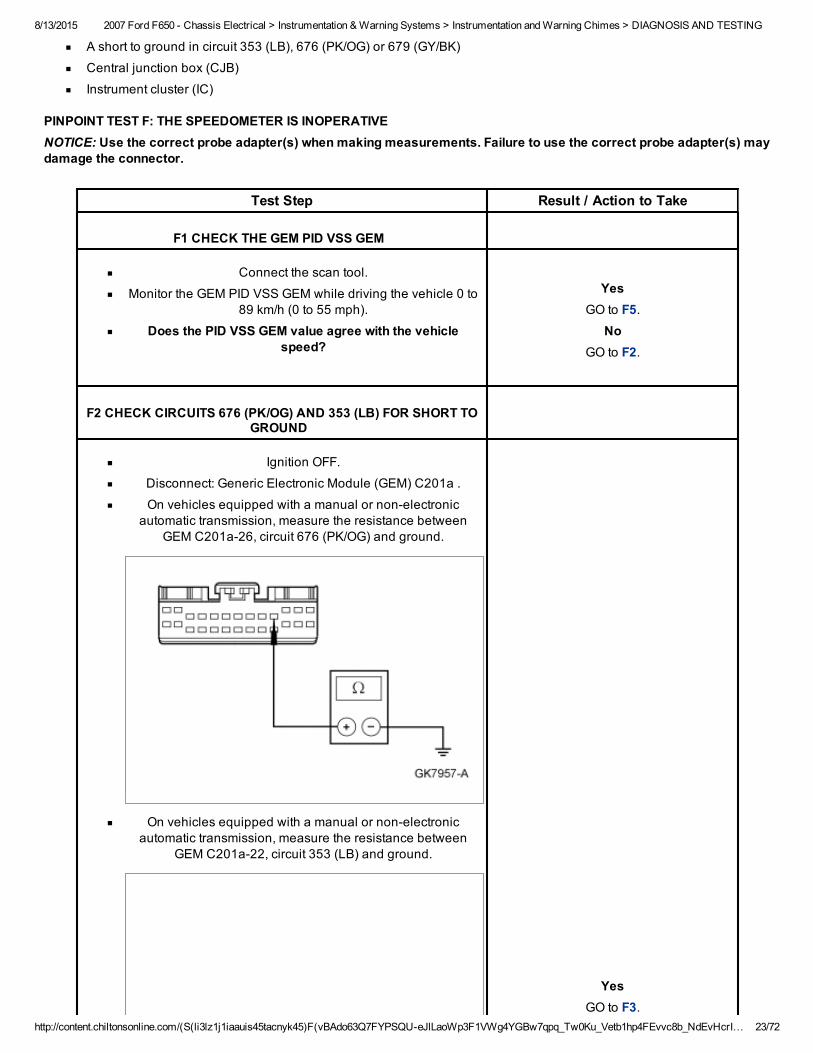
F1 CHECK THE GEM PID VSS GEM
Connect the scan tool.
Monitor the GEM PID VSS GEM while driving the vehicle 0 to89 km/h (0 to 55 mph).
Does the PID VSS GEM value agree with the vehiclespeed?
YesGO to F5.
NoGO to F2.
F2 CHECK CIRCUITS 676 (PK/OG) AND 353 (LB) FOR SHORT TOGROUND
Ignition OFF.
Disconnect: Generic Electronic Module (GEM) C201a .
On vehicles equipped with a manual or nonelectronicautomatic transmission, measure the resistance between
GEM C201a26, circuit 676 (PK/OG) and ground.
On vehicles equipped with a manual or nonelectronicautomatic transmission, measure the resistance between
GEM C201a22, circuit 353 (LB) and ground.
YesGO to F3.
8/13/2015 2007 Ford F650 Chassis Electrical > Instrumentation & Warning Systems > Instrumentation and Warning Chimes > DIAGNOSIS AND TESTING
http://content.chiltonsonline.com/(S(li3lz1j1iaauis45tacnyk45)F(vBAdo63Q7FYPSQUeJlLaoWp3F1VWg4YGBw7qpq_Tw0Ku_Vetb1hp4FEvvc8b_NdEvHcrI… 24/72
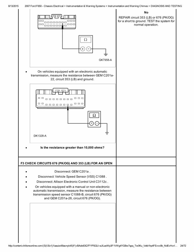
On vehicles equipped with an electronic automatictransmission, measure the resistance between GEM C201a
22, circuit 353 (LB) and ground.
Is the resistance greater than 10,000 ohms?
NoREPAIR circuit 353 (LB) or 676 (PK/OG)for a short to ground. TEST the system for
normal operation.
F3 CHECK CIRCUITS 676 (PK/OG) AND 353 (LB) FOR AN OPEN
Disconnect: GEM C201a .
Disconnect: Vehicle Speed Sensor (VSS) C1088 .
Disconnect: Allison Electronic Control Unit C3112c .
On vehicles equipped with a manual or nonelectronicautomatic transmission, measure the resistance betweentransmission speed sensor C1088B, circuit 676 (PK/OG)
and GEM C201a26, circuit 676 (PK/OG).
8/13/2015 2007 Ford F650 Chassis Electrical > Instrumentation & Warning Systems > Instrumentation and Warning Chimes > DIAGNOSIS AND TESTING
http://content.chiltonsonline.com/(S(li3lz1j1iaauis45tacnyk45)F(vBAdo63Q7FYPSQUeJlLaoWp3F1VWg4YGBw7qpq_Tw0Ku_Vetb1hp4FEvvc8b_NdEvHcrI… 25/72
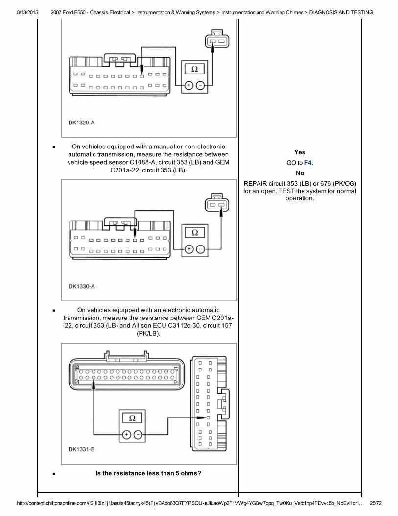
On vehicles equipped with a manual or nonelectronicautomatic transmission, measure the resistance betweenvehicle speed sensor C1088A, circuit 353 (LB) and GEM
C201a22, circuit 353 (LB).
On vehicles equipped with an electronic automatictransmission, measure the resistance between GEM C201a22, circuit 353 (LB) and Allison ECU C3112c30, circuit 157
(PK/LB).
Is the resistance less than 5 ohms?
YesGO to F4.
NoREPAIR circuit 353 (LB) or 676 (PK/OG)for an open. TEST the system for normal
operation.
8/13/2015 2007 Ford F650 Chassis Electrical > Instrumentation & Warning Systems > Instrumentation and Warning Chimes > DIAGNOSIS AND TESTING
http://content.chiltonsonline.com/(S(li3lz1j1iaauis45tacnyk45)F(vBAdo63Q7FYPSQUeJlLaoWp3F1VWg4YGBw7qpq_Tw0Ku_Vetb1hp4FEvvc8b_NdEvHcrI… 26/72
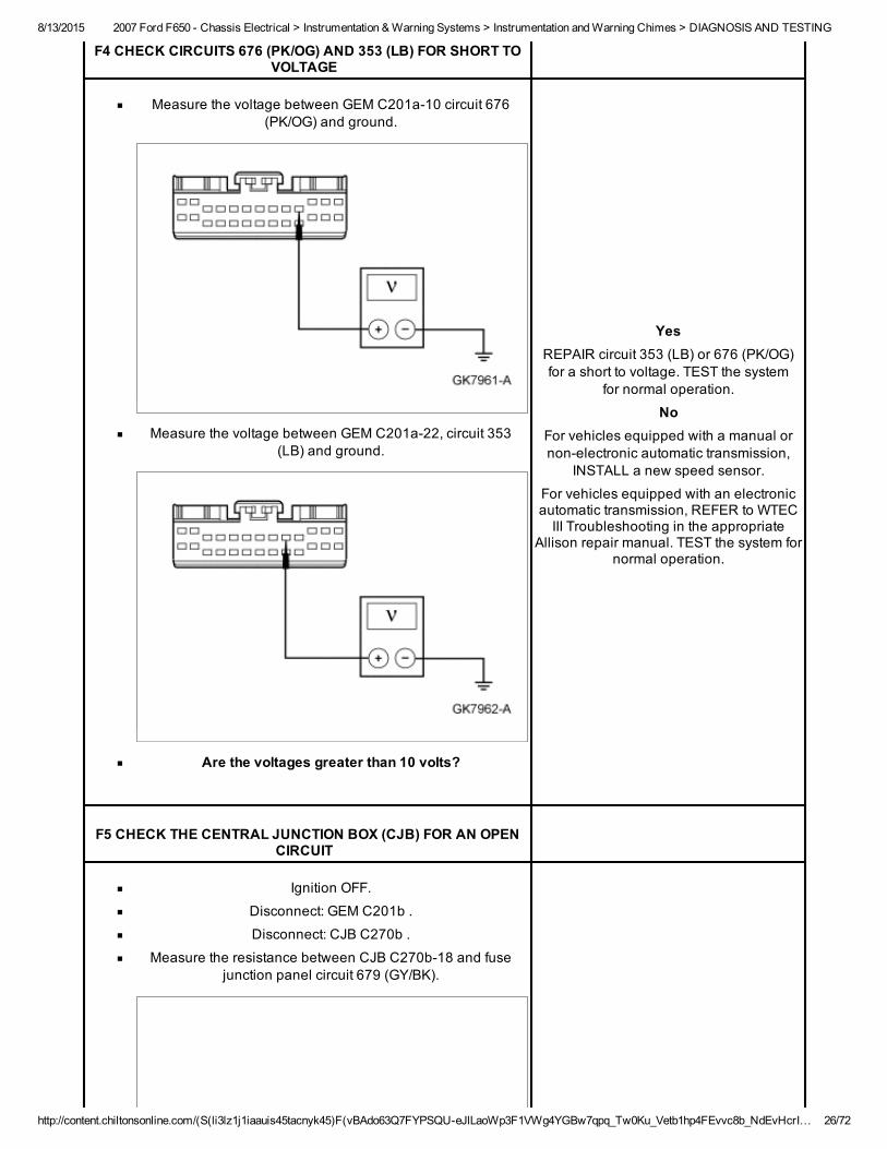
F4 CHECK CIRCUITS 676 (PK/OG) AND 353 (LB) FOR SHORT TOVOLTAGE
Measure the voltage between GEM C201a10 circuit 676(PK/OG) and ground.
Measure the voltage between GEM C201a22, circuit 353(LB) and ground.
Are the voltages greater than 10 volts?
YesREPAIR circuit 353 (LB) or 676 (PK/OG)for a short to voltage. TEST the system
for normal operation.
NoFor vehicles equipped with a manual ornonelectronic automatic transmission,
INSTALL a new speed sensor.
For vehicles equipped with an electronicautomatic transmission, REFER to WTECIII Troubleshooting in the appropriate
Allison repair manual. TEST the system fornormal operation.
F5 CHECK THE CENTRAL JUNCTION BOX (CJB) FOR AN OPENCIRCUIT
Ignition OFF.
Disconnect: GEM C201b .
Disconnect: CJB C270b .
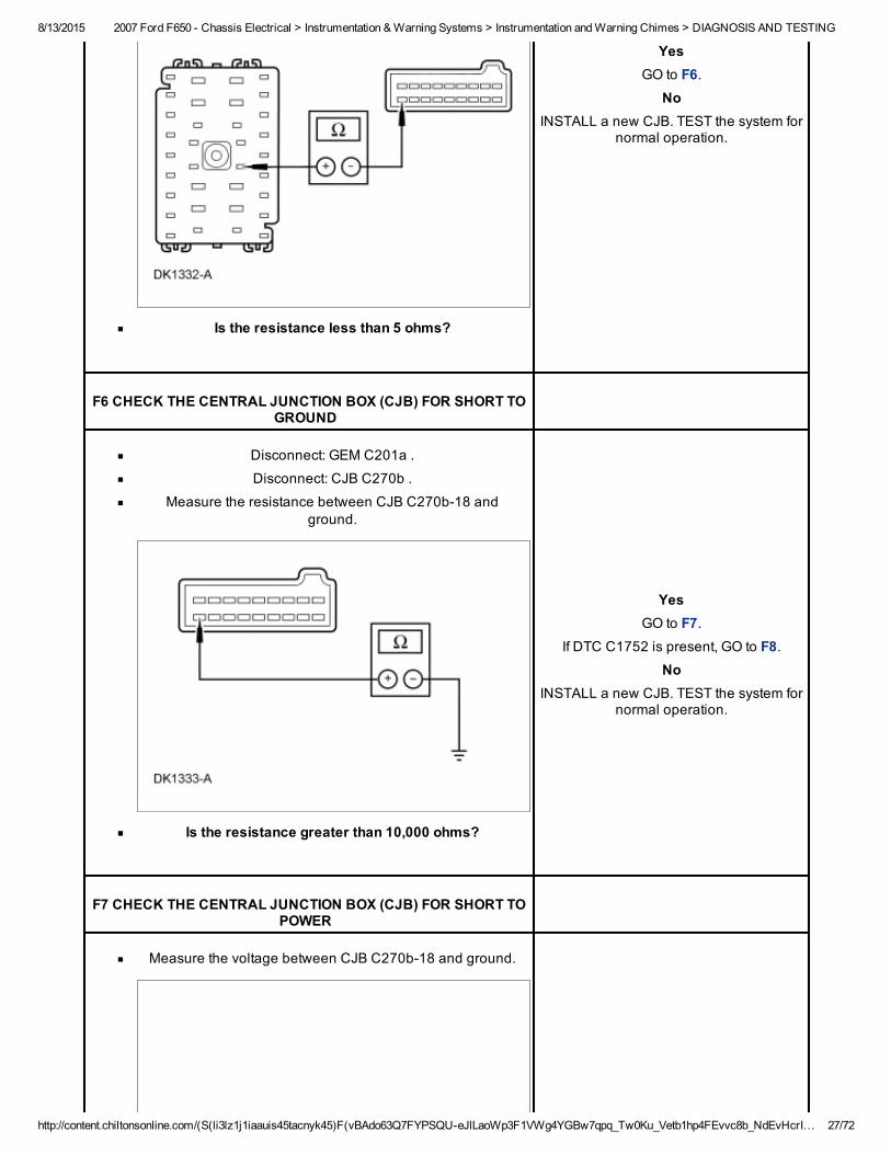
Measure the resistance between CJB C270b18 and fusejunction panel circuit 679 (GY/BK).
8/13/2015 2007 Ford F650 Chassis Electrical > Instrumentation & Warning Systems > Instrumentation and Warning Chimes > DIAGNOSIS AND TESTING
http://content.chiltonsonline.com/(S(li3lz1j1iaauis45tacnyk45)F(vBAdo63Q7FYPSQUeJlLaoWp3F1VWg4YGBw7qpq_Tw0Ku_Vetb1hp4FEvvc8b_NdEvHcrI… 27/72
Is the resistance less than 5 ohms?
YesGO to F6.
NoINSTALL a new CJB. TEST the system for
normal operation.
F6 CHECK THE CENTRAL JUNCTION BOX (CJB) FOR SHORT TOGROUND
Disconnect: GEM C201a .
Disconnect: CJB C270b .
Measure the resistance between CJB C270b18 andground.
Is the resistance greater than 10,000 ohms?
YesGO to F7.
If DTC C1752 is present, GO to F8.No
INSTALL a new CJB. TEST the system fornormal operation.
F7 CHECK THE CENTRAL JUNCTION BOX (CJB) FOR SHORT TOPOWER
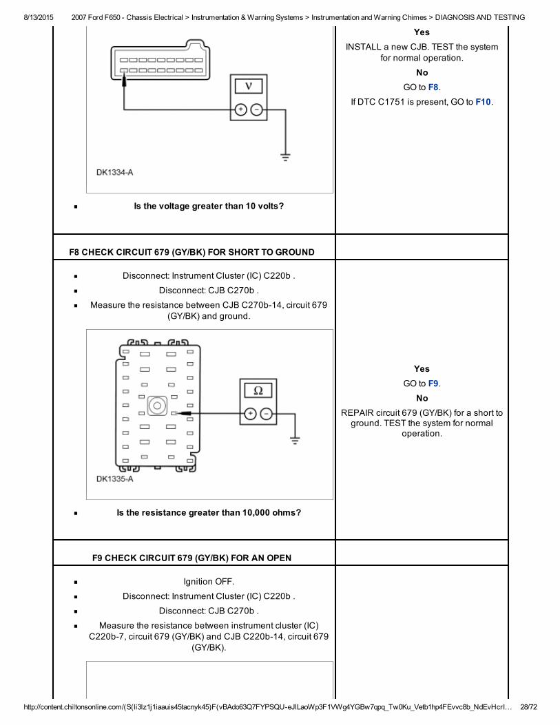
Measure the voltage between CJB C270b18 and ground.
8/13/2015 2007 Ford F650 Chassis Electrical > Instrumentation & Warning Systems > Instrumentation and Warning Chimes > DIAGNOSIS AND TESTING
http://content.chiltonsonline.com/(S(li3lz1j1iaauis45tacnyk45)F(vBAdo63Q7FYPSQUeJlLaoWp3F1VWg4YGBw7qpq_Tw0Ku_Vetb1hp4FEvvc8b_NdEvHcrI… 28/72
Is the voltage greater than 10 volts?
YesINSTALL a new CJB. TEST the system
for normal operation.
NoGO to F8.
If DTC C1751 is present, GO to F10.
F8 CHECK CIRCUIT 679 (GY/BK) FOR SHORT TO GROUND
Disconnect: Instrument Cluster (IC) C220b .
Disconnect: CJB C270b .
Measure the resistance between CJB C270b14, circuit 679(GY/BK) and ground.
Is the resistance greater than 10,000 ohms?
YesGO to F9.
NoREPAIR circuit 679 (GY/BK) for a short toground. TEST the system for normal
operation.
F9 CHECK CIRCUIT 679 (GY/BK) FOR AN OPEN
Ignition OFF.
Disconnect: Instrument Cluster (IC) C220b .
Disconnect: CJB C270b .
Measure the resistance between instrument cluster (IC)C220b7, circuit 679 (GY/BK) and CJB C220b14, circuit 679
(GY/BK).
8/13/2015 2007 Ford F650 Chassis Electrical > Instrumentation & Warning Systems > Instrumentation and Warning Chimes > DIAGNOSIS AND TESTING
http://content.chiltonsonline.com/(S(li3lz1j1iaauis45tacnyk45)F(vBAdo63Q7FYPSQUeJlLaoWp3F1VWg4YGBw7qpq_Tw0Ku_Vetb1hp4FEvvc8b_NdEvHcrI… 29/72
Is the resistance less than 5 ohms?
YesGO to F10.
NoREPAIR circuit 679 (GY/BK) for an open.TEST the system for normal operation.
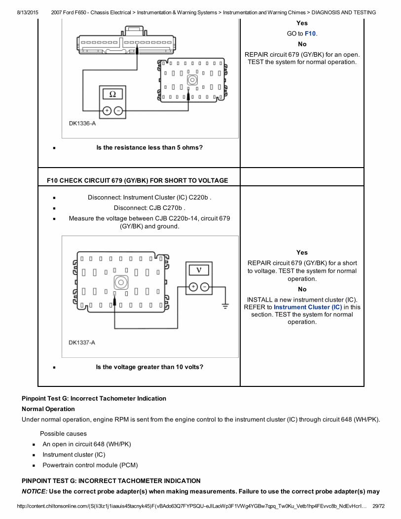
F10 CHECK CIRCUIT 679 (GY/BK) FOR SHORT TO VOLTAGE
Disconnect: Instrument Cluster (IC) C220b .
Disconnect: CJB C270b .
Measure the voltage between CJB C220b14, circuit 679(GY/BK) and ground.
Is the voltage greater than 10 volts?
YesREPAIR circuit 679 (GY/BK) for a shortto voltage. TEST the system for normal
operation.
NoINSTALL a new instrument cluster (IC).REFER to Instrument Cluster (IC) in thissection. TEST the system for normal
operation.
Pinpoint Test G: Incorrect Tachometer IndicationNormal OperationUnder normal operation, engine RPM is sent from the engine control to the instrument cluster (IC) through circuit 648 (WH/PK).
Possible causes
An open in circuit 648 (WH/PK)
Instrument cluster (IC)
Powertrain control module (PCM)
PINPOINT TEST G: INCORRECT TACHOMETER INDICATIONNOTICE: Use the correct probe adapter(s) when making measurements. Failure to use the correct probe adapter(s) may
8/13/2015 2007 Ford F650 Chassis Electrical > Instrumentation & Warning Systems > Instrumentation and Warning Chimes > DIAGNOSIS AND TESTING
http://content.chiltonsonline.com/(S(li3lz1j1iaauis45tacnyk45)F(vBAdo63Q7FYPSQUeJlLaoWp3F1VWg4YGBw7qpq_Tw0Ku_Vetb1hp4FEvvc8b_NdEvHcrI… 30/72
damage the connector.
Test Step Result / Action to Take
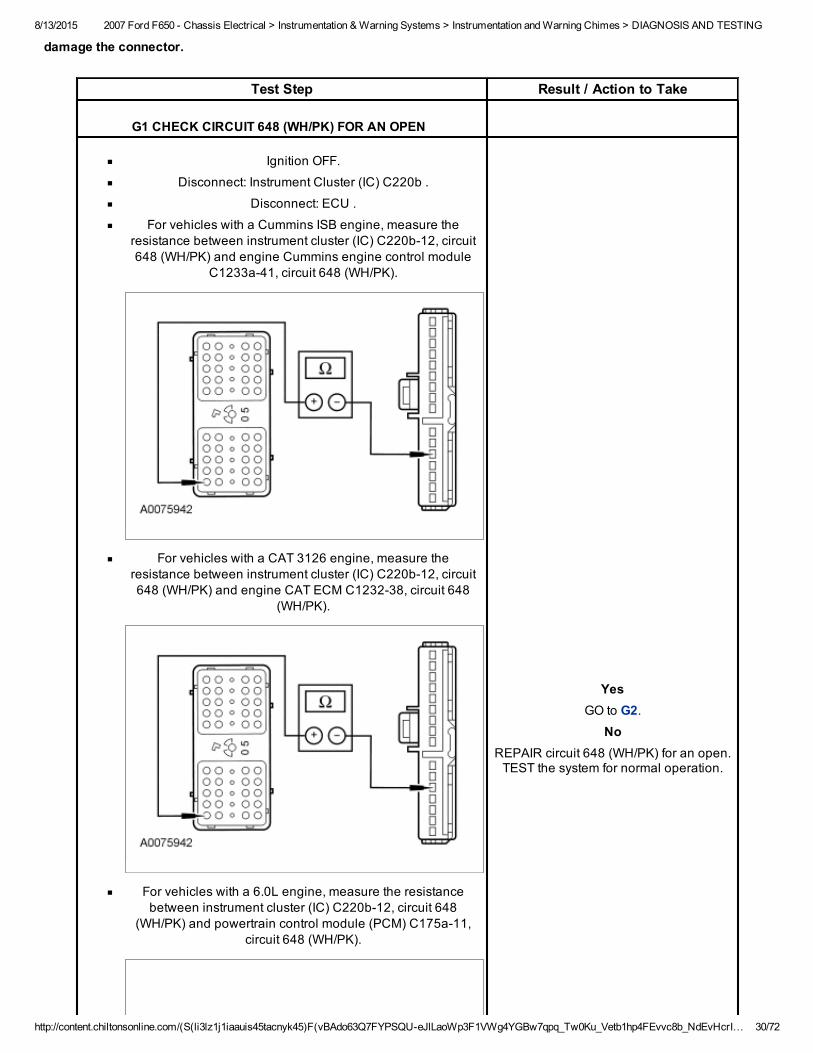
G1 CHECK CIRCUIT 648 (WH/PK) FOR AN OPEN
Ignition OFF.
Disconnect: Instrument Cluster (IC) C220b .
Disconnect: ECU .
For vehicles with a Cummins ISB engine, measure theresistance between instrument cluster (IC) C220b12, circuit648 (WH/PK) and engine Cummins engine control module
C1233a41, circuit 648 (WH/PK).
For vehicles with a CAT 3126 engine, measure theresistance between instrument cluster (IC) C220b12, circuit648 (WH/PK) and engine CAT ECM C123238, circuit 648
(WH/PK).
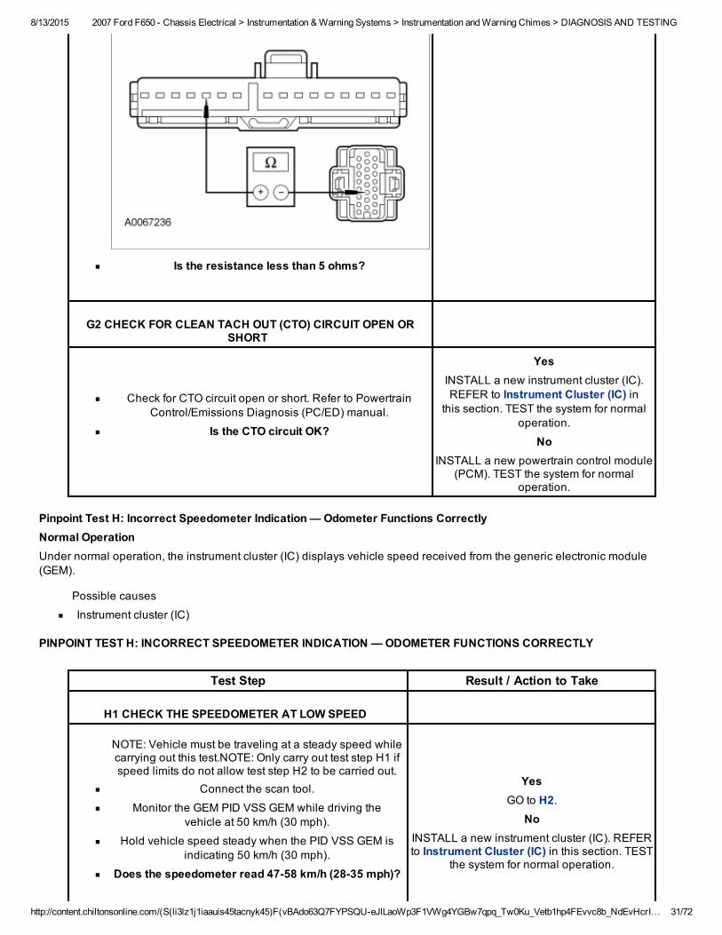
For vehicles with a 6.0L engine, measure the resistancebetween instrument cluster (IC) C220b12, circuit 648
(WH/PK) and powertrain control module (PCM) C175a11,circuit 648 (WH/PK).
YesGO to G2.
NoREPAIR circuit 648 (WH/PK) for an open.TEST the system for normal operation.
8/13/2015 2007 Ford F650 Chassis Electrical > Instrumentation & Warning Systems > Instrumentation and Warning Chimes > DIAGNOSIS AND TESTING
http://content.chiltonsonline.com/(S(li3lz1j1iaauis45tacnyk45)F(vBAdo63Q7FYPSQUeJlLaoWp3F1VWg4YGBw7qpq_Tw0Ku_Vetb1hp4FEvvc8b_NdEvHcrI… 31/72
Is the resistance less than 5 ohms?
G2 CHECK FOR CLEAN TACH OUT (CTO) CIRCUIT OPEN ORSHORT
Check for CTO circuit open or short. Refer to PowertrainControl/Emissions Diagnosis (PC/ED) manual.
Is the CTO circuit OK?
YesINSTALL a new instrument cluster (IC).REFER to Instrument Cluster (IC) in
this section. TEST the system for normaloperation.
NoINSTALL a new powertrain control module
(PCM). TEST the system for normaloperation.
Pinpoint Test H: Incorrect Speedometer Indication — Odometer Functions CorrectlyNormal OperationUnder normal operation, the instrument cluster (IC) displays vehicle speed received from the generic electronic module(GEM).
Possible causes
Instrument cluster (IC)
PINPOINT TEST H: INCORRECT SPEEDOMETER INDICATION — ODOMETER FUNCTIONS CORRECTLY
Test Step Result / Action to Take
H1 CHECK THE SPEEDOMETER AT LOW SPEED
NOTE: Vehicle must be traveling at a steady speed whilecarrying out this test.NOTE: Only carry out test step H1 ifspeed limits do not allow test step H2 to be carried out.
Connect the scan tool.
Monitor the GEM PID VSS GEM while driving thevehicle at 50 km/h (30 mph).
Hold vehicle speed steady when the PID VSS GEM isindicating 50 km/h (30 mph).
Does the speedometer read 4758 km/h (2835 mph)?
YesGO to H2.
NoINSTALL a new instrument cluster (IC). REFERto Instrument Cluster (IC) in this section. TEST
the system for normal operation.
8/13/2015 2007 Ford F650 Chassis Electrical > Instrumentation & Warning Systems > Instrumentation and Warning Chimes > DIAGNOSIS AND TESTING
http://content.chiltonsonline.com/(S(li3lz1j1iaauis45tacnyk45)F(vBAdo63Q7FYPSQUeJlLaoWp3F1VWg4YGBw7qpq_Tw0Ku_Vetb1hp4FEvvc8b_NdEvHcrI… 32/72
H2 CHECK THE SPEEDOMETER AT HIGH SPEED
NOTE: Vehicle must be traveling at a steady speed whilecarrying out this test.
Monitor the GEM PID VSS GEM while driving thevehicle at 100 km/h (60 mph).
Hold vehicle speed steady (set speed control, ifequipped) when the PID VSS GEM is indicating 100
km/h (60 mph).
Does the speedometer read 94108 km/h (5865mph)?
YesThe system is OK.
NoINSTALL a new instrument cluster (IC). REFERto Instrument Cluster (IC) in this section. TEST
the system for normal operation.
Pinpoint Test I: The Brake Warning Indicator Is Never On — Yellow ABS Warning IndicatorNormal OperationUnder normal operation, ground is provided to the instrument cluster (IC) to illuminate the indicator through circuit 603 (DG).
Possible causes
An open in circuit 603 (DG)
Instrument cluster (IC)
PINPOINT TEST I: THE BRAKE WARNING INDICATOR IS NEVER ON — YELLOW ABS WARNING INDICATORNOTICE: Use the correct probe adapter(s) when making measurements. Failure to use the correct probe adapter(s) maydamage the connector.
Test Step Result / Action to Take
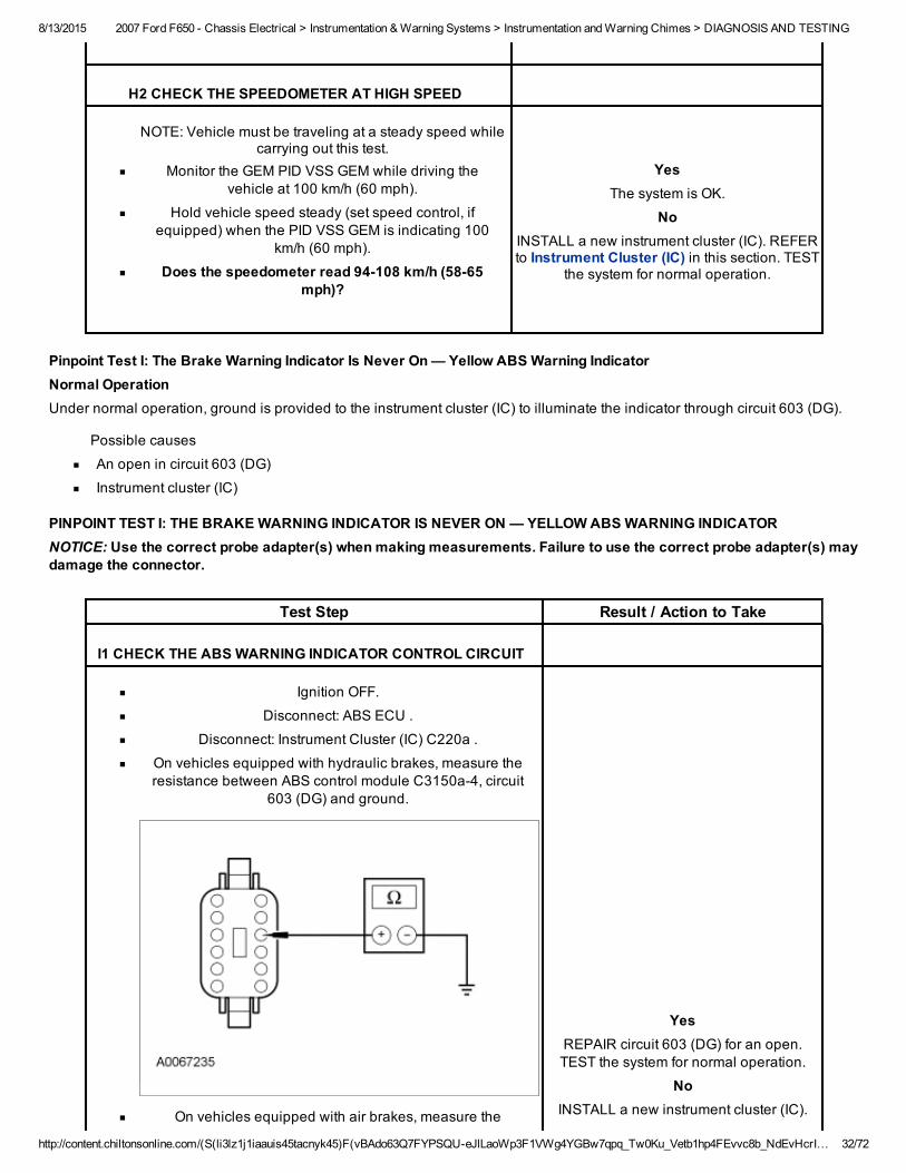
I1 CHECK THE ABS WARNING INDICATOR CONTROL CIRCUIT
Ignition OFF.
Disconnect: ABS ECU .
Disconnect: Instrument Cluster (IC) C220a .
On vehicles equipped with hydraulic brakes, measure theresistance between ABS control module C3150a4, circuit
603 (DG) and ground.
On vehicles equipped with air brakes, measure the
YesREPAIR circuit 603 (DG) for an open.TEST the system for normal operation.
NoINSTALL a new instrument cluster (IC).
8/13/2015 2007 Ford F650 Chassis Electrical > Instrumentation & Warning Systems > Instrumentation and Warning Chimes > DIAGNOSIS AND TESTING
http://content.chiltonsonline.com/(S(li3lz1j1iaauis45tacnyk45)F(vBAdo63Q7FYPSQUeJlLaoWp3F1VWg4YGBw7qpq_Tw0Ku_Vetb1hp4FEvvc8b_NdEvHcrI… 33/72
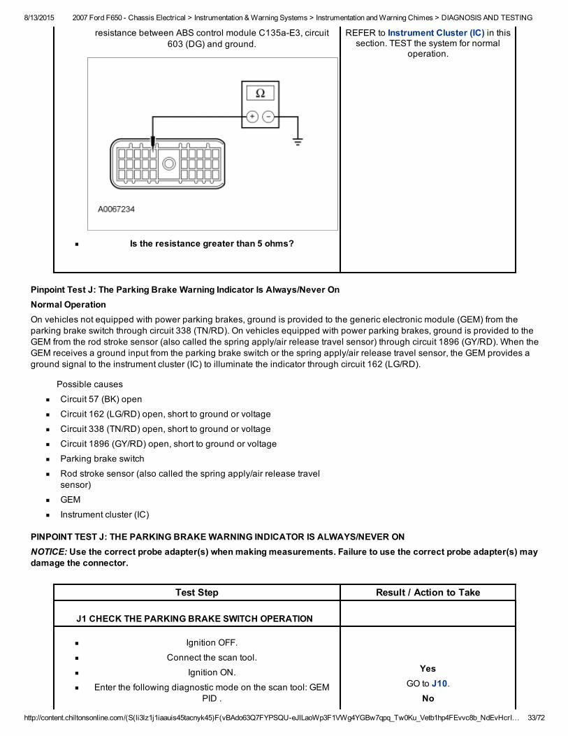
resistance between ABS control module C135aE3, circuit603 (DG) and ground.
Is the resistance greater than 5 ohms?
REFER to Instrument Cluster (IC) in thissection. TEST the system for normal
operation.
Pinpoint Test J: The Parking Brake Warning Indicator Is Always/Never OnNormal OperationOn vehicles not equipped with power parking brakes, ground is provided to the generic electronic module (GEM) from theparking brake switch through circuit 338 (TN/RD). On vehicles equipped with power parking brakes, ground is provided to theGEM from the rod stroke sensor (also called the spring apply/air release travel sensor) through circuit 1896 (GY/RD). When theGEM receives a ground input from the parking brake switch or the spring apply/air release travel sensor, the GEM provides aground signal to the instrument cluster (IC) to illuminate the indicator through circuit 162 (LG/RD).
Possible causes
Circuit 57 (BK) open
Circuit 162 (LG/RD) open, short to ground or voltage
Circuit 338 (TN/RD) open, short to ground or voltage
Circuit 1896 (GY/RD) open, short to ground or voltage
Parking brake switch
Rod stroke sensor (also called the spring apply/air release travelsensor)
GEM
Instrument cluster (IC)
PINPOINT TEST J: THE PARKING BRAKE WARNING INDICATOR IS ALWAYS/NEVER ONNOTICE: Use the correct probe adapter(s) when making measurements. Failure to use the correct probe adapter(s) maydamage the connector.
Test Step Result / Action to Take
J1 CHECK THE PARKING BRAKE SWITCH OPERATION
Ignition OFF.
Connect the scan tool.
Ignition ON.
Enter the following diagnostic mode on the scan tool: GEMPID .
YesGO to J10.
No
8/13/2015 2007 Ford F650 Chassis Electrical > Instrumentation & Warning Systems > Instrumentation and Warning Chimes > DIAGNOSIS AND TESTING
http://content.chiltonsonline.com/(S(li3lz1j1iaauis45tacnyk45)F(vBAdo63Q7FYPSQUeJlLaoWp3F1VWg4YGBw7qpq_Tw0Ku_Vetb1hp4FEvvc8b_NdEvHcrI… 34/72
Monitor the GEM PID PARK SW while engaging anddisengaging the parking brake.
Does the PID PARK SW indicate OFF when disengagedand ON when engaged?
If the PID always indicates OFF, GO toJ2.
If the PID always indicates ON, GO to J7.
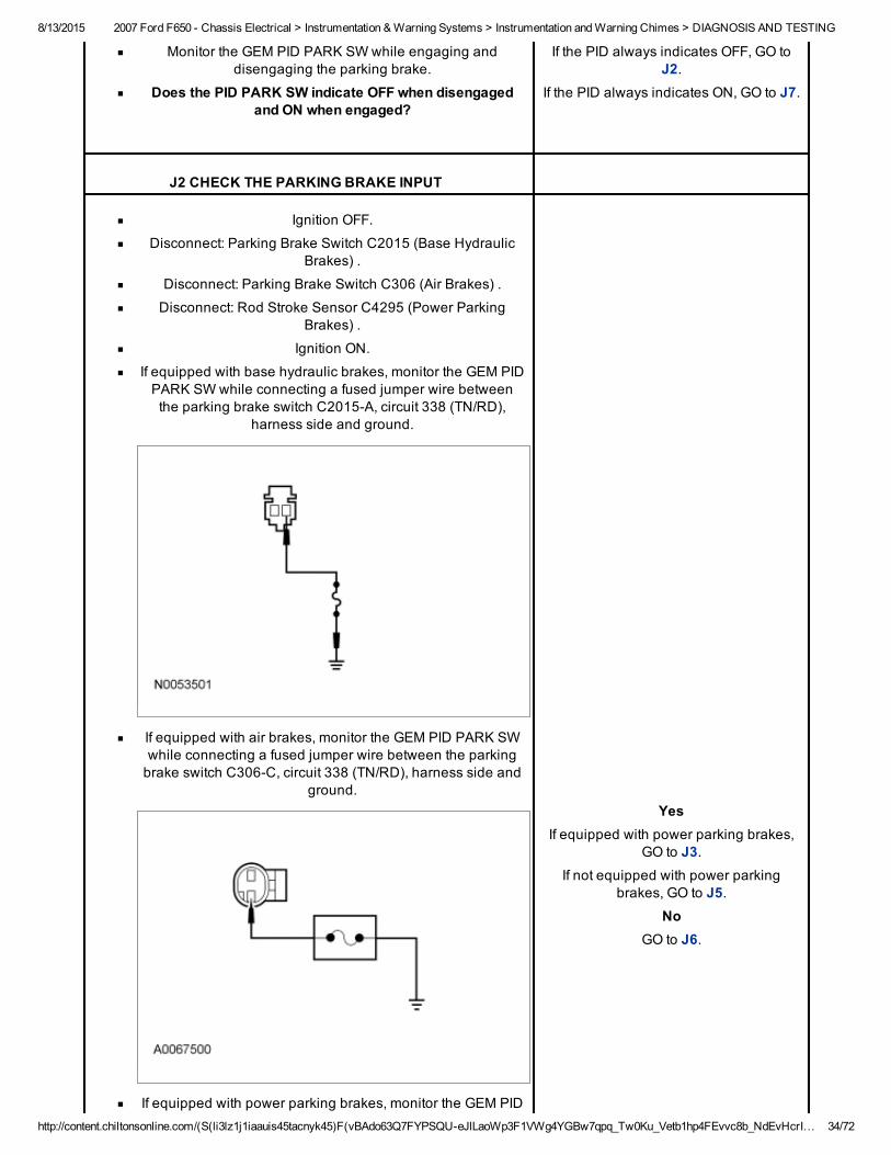
J2 CHECK THE PARKING BRAKE INPUT
Ignition OFF.
Disconnect: Parking Brake Switch C2015 (Base HydraulicBrakes) .
Disconnect: Parking Brake Switch C306 (Air Brakes) .
Disconnect: Rod Stroke Sensor C4295 (Power ParkingBrakes) .
Ignition ON.
If equipped with base hydraulic brakes, monitor the GEM PIDPARK SW while connecting a fused jumper wire betweenthe parking brake switch C2015A, circuit 338 (TN/RD),
harness side and ground.
If equipped with air brakes, monitor the GEM PID PARK SWwhile connecting a fused jumper wire between the parkingbrake switch C306C, circuit 338 (TN/RD), harness side and
ground.
If equipped with power parking brakes, monitor the GEM PID
YesIf equipped with power parking brakes,
GO to J3.If not equipped with power parking
brakes, GO to J5.No
GO to J6.
8/13/2015 2007 Ford F650 Chassis Electrical > Instrumentation & Warning Systems > Instrumentation and Warning Chimes > DIAGNOSIS AND TESTING
http://content.chiltonsonline.com/(S(li3lz1j1iaauis45tacnyk45)F(vBAdo63Q7FYPSQUeJlLaoWp3F1VWg4YGBw7qpq_Tw0Ku_Vetb1hp4FEvvc8b_NdEvHcrI… 35/72
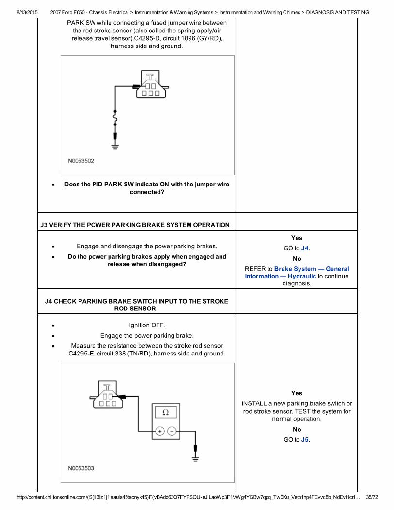
PARK SW while connecting a fused jumper wire betweenthe rod stroke sensor (also called the spring apply/airrelease travel sensor) C4295D, circuit 1896 (GY/RD),
harness side and ground.
Does the PID PARK SW indicate ON with the jumper wireconnected?
J3 VERIFY THE POWER PARKING BRAKE SYSTEM OPERATION
Engage and disengage the power parking brakes.
Do the power parking brakes apply when engaged andrelease when disengaged?
YesGO to J4.
NoREFER to Brake System — GeneralInformation — Hydraulic to continue
diagnosis.
J4 CHECK PARKING BRAKE SWITCH INPUT TO THE STROKEROD SENSOR
Ignition OFF.
Engage the power parking brake.
Measure the resistance between the stroke rod sensorC4295E, circuit 338 (TN/RD), harness side and ground.
YesINSTALL a new parking brake switch orrod stroke sensor. TEST the system for
normal operation.
NoGO to J5.
8/13/2015 2007 Ford F650 Chassis Electrical > Instrumentation & Warning Systems > Instrumentation and Warning Chimes > DIAGNOSIS AND TESTING
http://content.chiltonsonline.com/(S(li3lz1j1iaauis45tacnyk45)F(vBAdo63Q7FYPSQUeJlLaoWp3F1VWg4YGBw7qpq_Tw0Ku_Vetb1hp4FEvvc8b_NdEvHcrI… 36/72
Is the resistance less than 5 ohms?
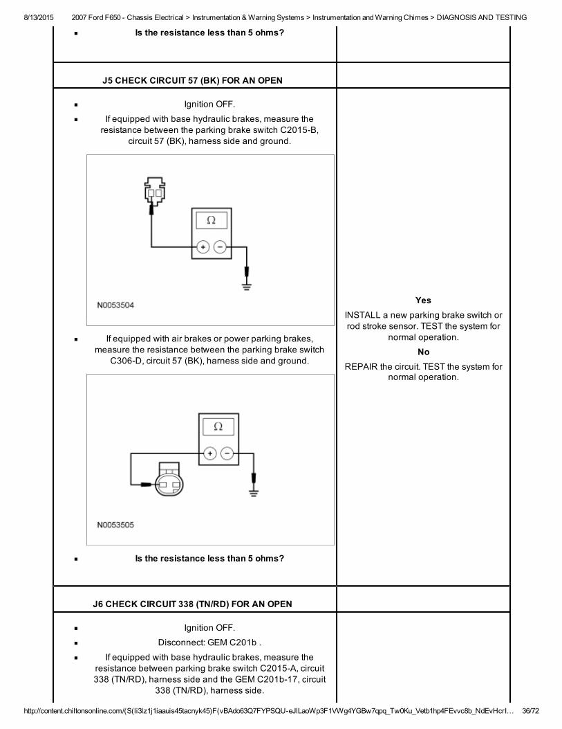
J5 CHECK CIRCUIT 57 (BK) FOR AN OPEN
Ignition OFF.
If equipped with base hydraulic brakes, measure theresistance between the parking brake switch C2015B,
circuit 57 (BK), harness side and ground.
If equipped with air brakes or power parking brakes,measure the resistance between the parking brake switch
C306D, circuit 57 (BK), harness side and ground.
Is the resistance less than 5 ohms?
YesINSTALL a new parking brake switch orrod stroke sensor. TEST the system for
normal operation.
NoREPAIR the circuit. TEST the system for
normal operation.
J6 CHECK CIRCUIT 338 (TN/RD) FOR AN OPEN
Ignition OFF.
Disconnect: GEM C201b .
If equipped with base hydraulic brakes, measure theresistance between parking brake switch C2015A, circuit338 (TN/RD), harness side and the GEM C201b17, circuit
338 (TN/RD), harness side.
8/13/2015 2007 Ford F650 Chassis Electrical > Instrumentation & Warning Systems > Instrumentation and Warning Chimes > DIAGNOSIS AND TESTING
http://content.chiltonsonline.com/(S(li3lz1j1iaauis45tacnyk45)F(vBAdo63Q7FYPSQUeJlLaoWp3F1VWg4YGBw7qpq_Tw0Ku_Vetb1hp4FEvvc8b_NdEvHcrI… 37/72
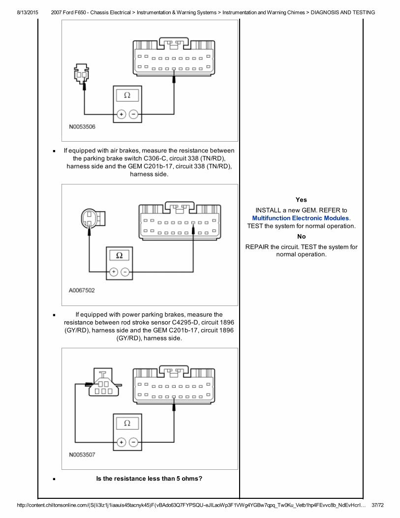
If equipped with air brakes, measure the resistance betweenthe parking brake switch C306C, circuit 338 (TN/RD),
harness side and the GEM C201b17, circuit 338 (TN/RD),harness side.
If equipped with power parking brakes, measure theresistance between rod stroke sensor C4295D, circuit 1896(GY/RD), harness side and the GEM C201b17, circuit 1896
(GY/RD), harness side.
Is the resistance less than 5 ohms?
YesINSTALL a new GEM. REFER toMultifunction Electronic Modules.
TEST the system for normal operation.
NoREPAIR the circuit. TEST the system for
normal operation.
8/13/2015 2007 Ford F650 Chassis Electrical > Instrumentation & Warning Systems > Instrumentation and Warning Chimes > DIAGNOSIS AND TESTING
http://content.chiltonsonline.com/(S(li3lz1j1iaauis45tacnyk45)F(vBAdo63Q7FYPSQUeJlLaoWp3F1VWg4YGBw7qpq_Tw0Ku_Vetb1hp4FEvvc8b_NdEvHcrI… 38/72
J7 CHECK THE PARKING BRAKE SWITCH
Ignition OFF.
Disconnect: Parking Brake Switch C2015 (Base HydraulicBrakes) .
Disconnect: Parking Brake Switch C306 (Air Brakes) .
Ignition ON.
Monitor the GEM PID PARK SW with the parking brakeswitch disconnected.
Does the PID PARK SW indicate OFF with the switchdisconnected?
YesINSTALL a new parking brake switch.TEST the system for normal operation.
NoIf equipped with power parking brakes,
GO to J8.If not equipped with power parking brakes,
GO to J9.
J8 CHECK THE STROKE ROD SENSOR FOR A SHORT TOGROUND
Ignition OFF.
Disconnect: Stroke Rod Sensor C4295 .
Monitor the GEM PID PARK SW with the parking brakeswitch disconnected.
Does the PID PARK SW indicate OFF with the switchdisconnected?
YesINSTALL a new stroke rod sensor.
REFER to Brake System — GeneralInformation — Hydraulic. TEST the
system for normal operation.
NoGO to J9.
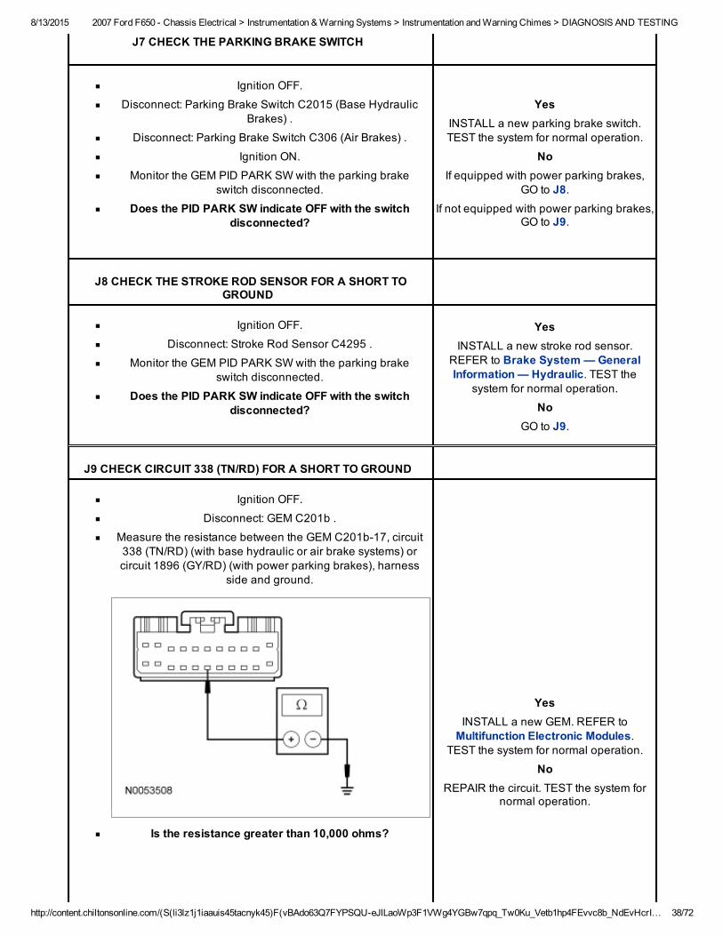
J9 CHECK CIRCUIT 338 (TN/RD) FOR A SHORT TO GROUND
Ignition OFF.
Disconnect: GEM C201b .
Measure the resistance between the GEM C201b17, circuit338 (TN/RD) (with base hydraulic or air brake systems) orcircuit 1896 (GY/RD) (with power parking brakes), harness
side and ground.
Is the resistance greater than 10,000 ohms?
YesINSTALL a new GEM. REFER toMultifunction Electronic Modules.
TEST the system for normal operation.
NoREPAIR the circuit. TEST the system for
normal operation.
8/13/2015 2007 Ford F650 Chassis Electrical > Instrumentation & Warning Systems > Instrumentation and Warning Chimes > DIAGNOSIS AND TESTING
http://content.chiltonsonline.com/(S(li3lz1j1iaauis45tacnyk45)F(vBAdo63Q7FYPSQUeJlLaoWp3F1VWg4YGBw7qpq_Tw0Ku_Vetb1hp4FEvvc8b_NdEvHcrI… 39/72
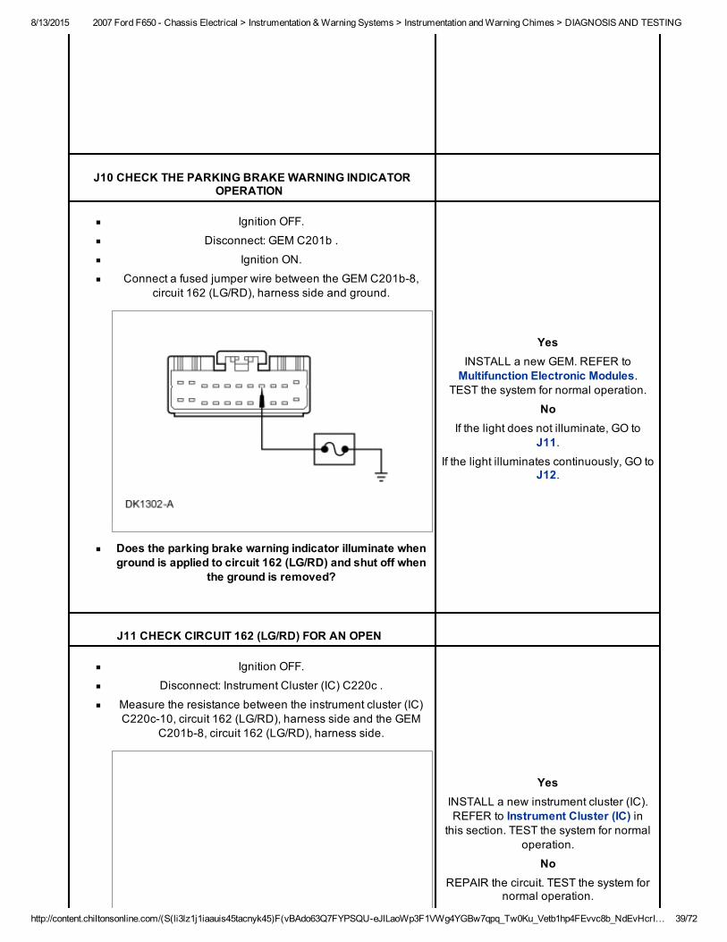
J10 CHECK THE PARKING BRAKE WARNING INDICATOROPERATION
Ignition OFF.
Disconnect: GEM C201b .
Ignition ON.
Connect a fused jumper wire between the GEM C201b8,circuit 162 (LG/RD), harness side and ground.
Does the parking brake warning indicator illuminate whenground is applied to circuit 162 (LG/RD) and shut off when
the ground is removed?
YesINSTALL a new GEM. REFER toMultifunction Electronic Modules.
TEST the system for normal operation.
NoIf the light does not illuminate, GO to
J11.If the light illuminates continuously, GO to
J12.
J11 CHECK CIRCUIT 162 (LG/RD) FOR AN OPEN
Ignition OFF.
Disconnect: Instrument Cluster (IC) C220c .
Measure the resistance between the instrument cluster (IC)C220c10, circuit 162 (LG/RD), harness side and the GEM
C201b8, circuit 162 (LG/RD), harness side.
YesINSTALL a new instrument cluster (IC).REFER to Instrument Cluster (IC) in
this section. TEST the system for normaloperation.
NoREPAIR the circuit. TEST the system for
normal operation.
8/13/2015 2007 Ford F650 Chassis Electrical > Instrumentation & Warning Systems > Instrumentation and Warning Chimes > DIAGNOSIS AND TESTING
http://content.chiltonsonline.com/(S(li3lz1j1iaauis45tacnyk45)F(vBAdo63Q7FYPSQUeJlLaoWp3F1VWg4YGBw7qpq_Tw0Ku_Vetb1hp4FEvvc8b_NdEvHcrI… 40/72
Is the resistance less than 5 ohms?
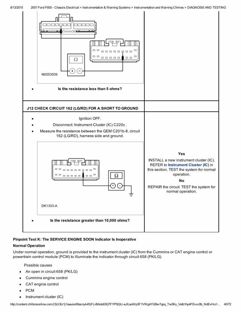
J12 CHECK CIRCUIT 162 (LG/RD) FOR A SHORT TO GROUND
Ignition OFF.
Disconnect: Instrument Cluster (IC) C220c .
Measure the resistance between the GEM C201b8, circuit162 (LG/RD), harness side and ground.
Is the resistance greater than 10,000 ohms?
YesINSTALL a new instrument cluster (IC).REFER to Instrument Cluster (IC) in
this section. TEST the system for normaloperation.
NoREPAIR the circuit. TEST the system for
normal operation.
Pinpoint Test K: The SERVICE ENGINE SOON Indicator Is InoperativeNormal OperationUnder normal operation, ground is provided to the instrument cluster (IC) from the Cummins or CAT engine control orpowertrain control module (PCM) to illuminate the indicator through circuit 658 (PK/LG).
Possible causes
An open in circuit 658 (PK/LG)
Cummins engine control
CAT engine control
PCM
Instrument cluster (IC)
8/13/2015 2007 Ford F650 Chassis Electrical > Instrumentation & Warning Systems > Instrumentation and Warning Chimes > DIAGNOSIS AND TESTING
http://content.chiltonsonline.com/(S(li3lz1j1iaauis45tacnyk45)F(vBAdo63Q7FYPSQUeJlLaoWp3F1VWg4YGBw7qpq_Tw0Ku_Vetb1hp4FEvvc8b_NdEvHcrI… 41/72
PINPOINT TEST K: THE SERVICE ENGINE SOON INDICATOR IS INOPERATIVENOTICE: Use the correct probe adapter(s) when making measurements. Failure to use the correct probe adapter(s) maydamage the connector.
Test Step Result / Action to Take
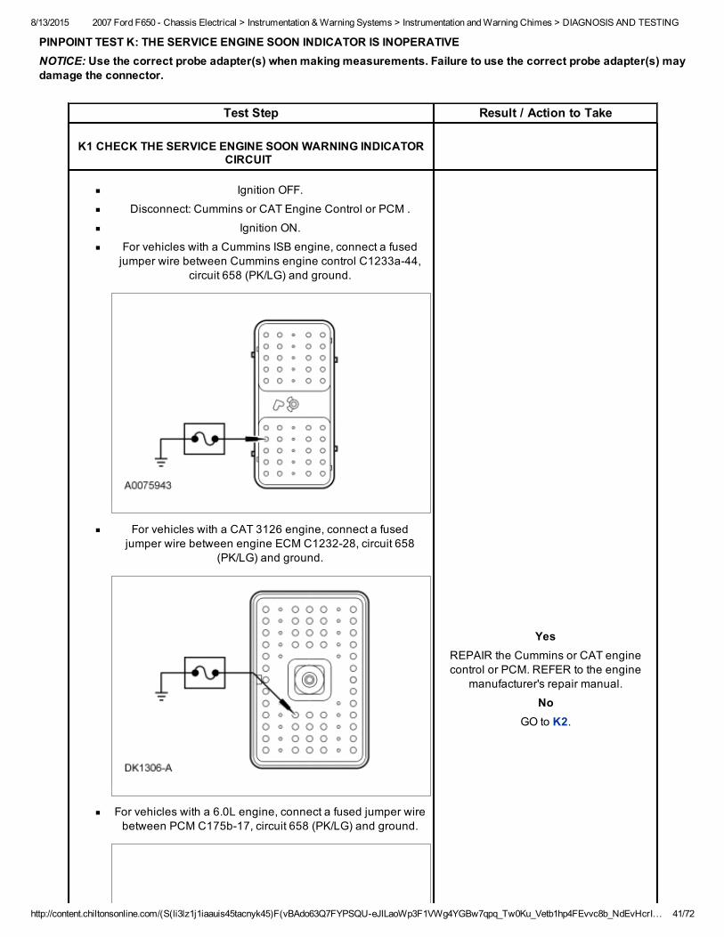
K1 CHECK THE SERVICE ENGINE SOON WARNING INDICATORCIRCUIT
Ignition OFF.
Disconnect: Cummins or CAT Engine Control or PCM .
Ignition ON.
For vehicles with a Cummins ISB engine, connect a fusedjumper wire between Cummins engine control C1233a44,
circuit 658 (PK/LG) and ground.
For vehicles with a CAT 3126 engine, connect a fusedjumper wire between engine ECM C123228, circuit 658
(PK/LG) and ground.
For vehicles with a 6.0L engine, connect a fused jumper wirebetween PCM C175b17, circuit 658 (PK/LG) and ground.
YesREPAIR the Cummins or CAT enginecontrol or PCM. REFER to the engine
manufacturer's repair manual.
NoGO to K2.
8/13/2015 2007 Ford F650 Chassis Electrical > Instrumentation & Warning Systems > Instrumentation and Warning Chimes > DIAGNOSIS AND TESTING
http://content.chiltonsonline.com/(S(li3lz1j1iaauis45tacnyk45)F(vBAdo63Q7FYPSQUeJlLaoWp3F1VWg4YGBw7qpq_Tw0Ku_Vetb1hp4FEvvc8b_NdEvHcrI… 42/72
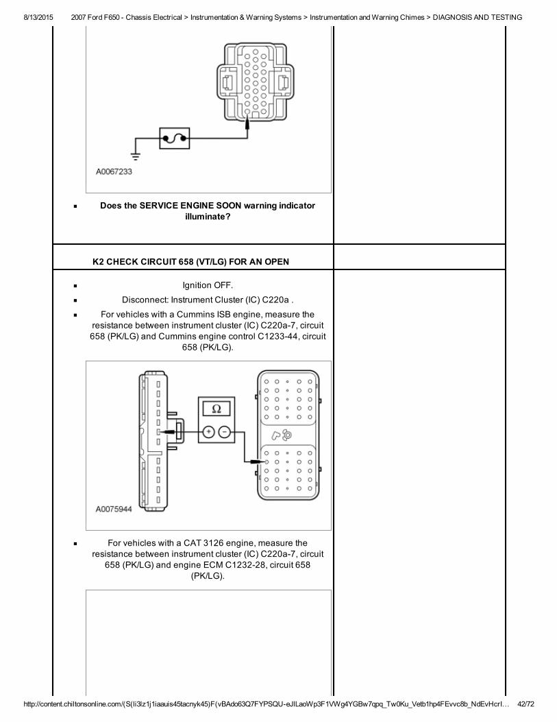
Does the SERVICE ENGINE SOON warning indicatorilluminate?
K2 CHECK CIRCUIT 658 (VT/LG) FOR AN OPEN
Ignition OFF.
Disconnect: Instrument Cluster (IC) C220a .
For vehicles with a Cummins ISB engine, measure theresistance between instrument cluster (IC) C220a7, circuit658 (PK/LG) and Cummins engine control C123344, circuit
658 (PK/LG).
For vehicles with a CAT 3126 engine, measure theresistance between instrument cluster (IC) C220a7, circuit
658 (PK/LG) and engine ECM C123228, circuit 658(PK/LG).
8/13/2015 2007 Ford F650 Chassis Electrical > Instrumentation & Warning Systems > Instrumentation and Warning Chimes > DIAGNOSIS AND TESTING
http://content.chiltonsonline.com/(S(li3lz1j1iaauis45tacnyk45)F(vBAdo63Q7FYPSQUeJlLaoWp3F1VWg4YGBw7qpq_Tw0Ku_Vetb1hp4FEvvc8b_NdEvHcrI… 43/72
Click to Enlarge
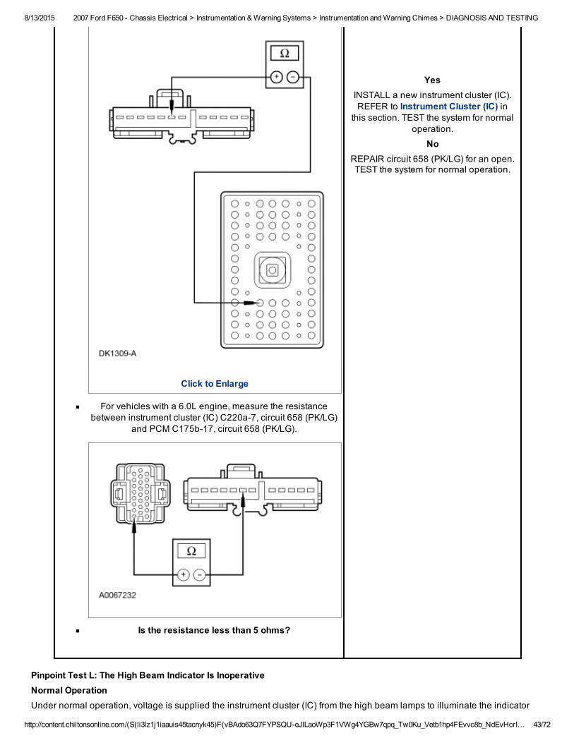
For vehicles with a 6.0L engine, measure the resistancebetween instrument cluster (IC) C220a7, circuit 658 (PK/LG)
and PCM C175b17, circuit 658 (PK/LG).
Is the resistance less than 5 ohms?
YesINSTALL a new instrument cluster (IC).REFER to Instrument Cluster (IC) in
this section. TEST the system for normaloperation.
NoREPAIR circuit 658 (PK/LG) for an open.TEST the system for normal operation.
Pinpoint Test L: The High Beam Indicator Is InoperativeNormal OperationUnder normal operation, voltage is supplied the instrument cluster (IC) from the high beam lamps to illuminate the indicator
8/13/2015 2007 Ford F650 Chassis Electrical > Instrumentation & Warning Systems > Instrumentation and Warning Chimes > DIAGNOSIS AND TESTING
http://content.chiltonsonline.com/(S(li3lz1j1iaauis45tacnyk45)F(vBAdo63Q7FYPSQUeJlLaoWp3F1VWg4YGBw7qpq_Tw0Ku_Vetb1hp4FEvvc8b_NdEvHcrI… 44/72
through circuit 12 (LG/BK).
Possible causes
An open in circuit 12 (LG/BK)
Instrument cluster (IC)
PINPOINT TEST L: THE HIGH BEAM INDICATOR IS INOPERATIVENOTICE: Use the correct probe adapter(s) when making measurements. Failure to use the correct probe adapter(s) maydamage the connector.
Test Step Result / Action to Take
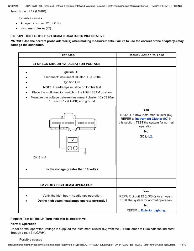
L1 CHECK CIRCUIT 12 (LG/BK) FOR VOLTAGE
Ignition OFF.
Disconnect: Instrument Cluster (IC) C220a .
Ignition ON.
NOTE: Headlamps must be on for this test.Place the multifunction switch in the HIGH BEAM position.
Measure the voltage between instrument cluster (IC) C220a10, circuit 12 (LG/BK) and ground.
Is the voltage greater than 10 volts?
YesINSTALL a new instrument cluster (IC).REFER to Instrument Cluster (IC) in
this section. TEST the system for normaloperation.
NoGO to L2.
L2 VERIFY HIGH BEAM OPERATION
Verify the high beam headlamps operation.
Do the high beam headlamps operate correctly?
YesREPAIR circuit 12 (LG/BK) for an open.TEST the system for normal operation.
NoREFER to Exterior Lighting.
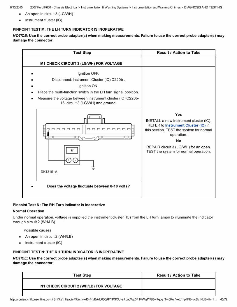
Pinpoint Test M: The LH Turn Indicator Is InoperativeNormal OperationUnder normal operation, voltage is supplied the instrument cluster (IC) from the LH turn lamps to illuminate the indicatorthrough circuit 3 (LG/WH).
Possible causes
8/13/2015 2007 Ford F650 Chassis Electrical > Instrumentation & Warning Systems > Instrumentation and Warning Chimes > DIAGNOSIS AND TESTING
http://content.chiltonsonline.com/(S(li3lz1j1iaauis45tacnyk45)F(vBAdo63Q7FYPSQUeJlLaoWp3F1VWg4YGBw7qpq_Tw0Ku_Vetb1hp4FEvvc8b_NdEvHcrI… 45/72
An open in circuit 3 (LG/WH)
Instrument cluster (IC)
PINPOINT TEST M: THE LH TURN INDICATOR IS INOPERATIVENOTICE: Use the correct probe adapter(s) when making measurements. Failure to use the correct probe adapter(s) maydamage the connector.
Test Step Result / Action to Take
M1 CHECK CIRCUIT 3 (LG/WH) FOR VOLTAGE
Ignition OFF.
Disconnect: Instrument Cluster (IC) C220b .
Ignition ON.
Place the multifunction switch in the LH turn signal position.
Measure the voltage between instrument cluster (IC) C220b16, circuit 3 (LG/WH) and ground.
Does the voltage fluctuate between 010 volts?
YesINSTALL a new instrument cluster (IC).REFER to Instrument Cluster (IC) in
this section. TEST the system for normaloperation.
NoREPAIR circuit 3 (LG/WH) for an open.TEST the system for normal operation.
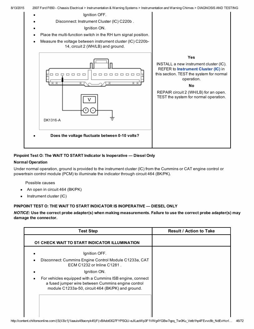
Pinpoint Test N: The RH Turn Indicator Is InoperativeNormal OperationUnder normal operation, voltage is supplied the instrument cluster (IC) from the LH turn lamps to illuminate the indicatorthrough circuit 2 (WH/LB).
Possible causes
An open in circuit 2 (WH/LB)
Instrument cluster (IC)
PINPOINT TEST N: THE RH TURN INDICATOR IS INOPERATIVENOTICE: Use the correct probe adapter(s) when making measurements. Failure to use the correct probe adapter(s) maydamage the connector.
Test Step Result / Action to Take
N1 CHECK CIRCUIT 2 (WH/LB) FOR VOLTAGE
8/13/2015 2007 Ford F650 Chassis Electrical > Instrumentation & Warning Systems > Instrumentation and Warning Chimes > DIAGNOSIS AND TESTING
http://content.chiltonsonline.com/(S(li3lz1j1iaauis45tacnyk45)F(vBAdo63Q7FYPSQUeJlLaoWp3F1VWg4YGBw7qpq_Tw0Ku_Vetb1hp4FEvvc8b_NdEvHcrI… 46/72
Ignition OFF.
Disconnect: Instrument Cluster (IC) C220b .
Ignition ON.
Place the multifunction switch in the RH turn signal position.
Measure the voltage between instrument cluster (IC) C220b14, circuit 2 (WH/LB) and ground.
Does the voltage fluctuate between 010 volts?
YesINSTALL a new instrument cluster (IC).REFER to Instrument Cluster (IC) in
this section. TEST the system for normaloperation.
NoREPAIR circuit 2 (WH/LB) for an open.TEST the system for normal operation.
Pinpoint Test O: The WAIT TO START Indicator Is Inoperative — Diesel OnlyNormal OperationUnder normal operation, ground is provided to the instrument cluster (IC) from the Cummins or CAT engine control orpowertrain control module (PCM) to illuminate the indicator through circuit 464 (BK/PK).
Possible causes
An open in circuit 464 (BK/PK)
Instrument cluster (IC)
PINPOINT TEST O: THE WAIT TO START INDICATOR IS INOPERATIVE — DIESEL ONLYNOTICE: Use the correct probe adapter(s) when making measurements. Failure to use the correct probe adapter(s) maydamage the connector.
Test Step Result / Action to Take
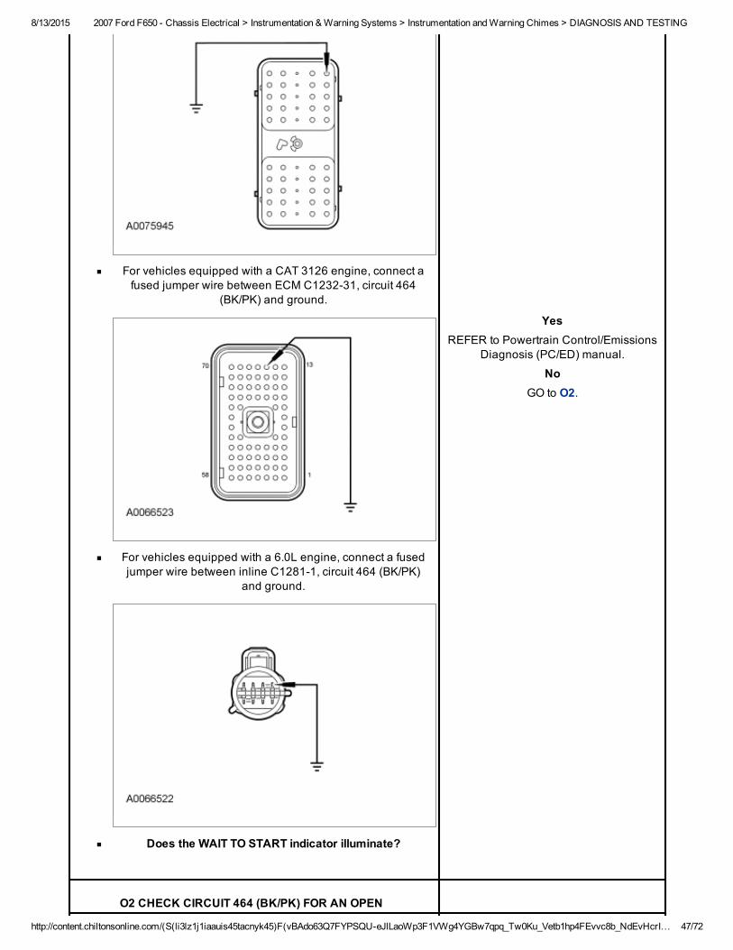
O1 CHECK WAIT TO START INDICATOR ILLUMINATION
Ignition OFF.
Disconnect: Cummins Engine Control Module C1233a, CATECM C1232 or Inline C1281 .
Ignition ON.
For vehicles equipped with a Cummins ISB engine, connecta fused jumper wire between Cummins engine controlmodule C1233a50, circuit 464 (BK/PK) and ground.
8/13/2015 2007 Ford F650 Chassis Electrical > Instrumentation & Warning Systems > Instrumentation and Warning Chimes > DIAGNOSIS AND TESTING
http://content.chiltonsonline.com/(S(li3lz1j1iaauis45tacnyk45)F(vBAdo63Q7FYPSQUeJlLaoWp3F1VWg4YGBw7qpq_Tw0Ku_Vetb1hp4FEvvc8b_NdEvHcrI… 47/72
For vehicles equipped with a CAT 3126 engine, connect afused jumper wire between ECM C123231, circuit 464
(BK/PK) and ground.
For vehicles equipped with a 6.0L engine, connect a fusedjumper wire between inline C12811, circuit 464 (BK/PK)
and ground.
Does the WAIT TO START indicator illuminate?
YesREFER to Powertrain Control/Emissions
Diagnosis (PC/ED) manual.
NoGO to O2.
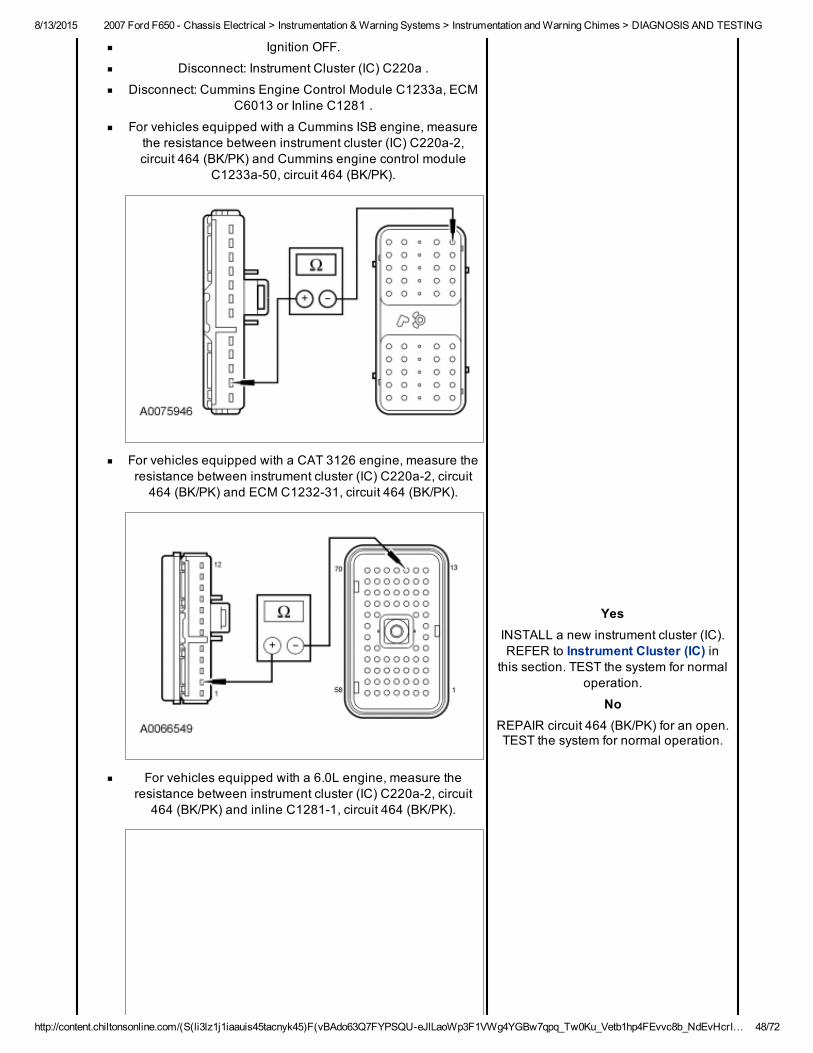
O2 CHECK CIRCUIT 464 (BK/PK) FOR AN OPEN
8/13/2015 2007 Ford F650 Chassis Electrical > Instrumentation & Warning Systems > Instrumentation and Warning Chimes > DIAGNOSIS AND TESTING
http://content.chiltonsonline.com/(S(li3lz1j1iaauis45tacnyk45)F(vBAdo63Q7FYPSQUeJlLaoWp3F1VWg4YGBw7qpq_Tw0Ku_Vetb1hp4FEvvc8b_NdEvHcrI… 48/72
Ignition OFF.
Disconnect: Instrument Cluster (IC) C220a .
Disconnect: Cummins Engine Control Module C1233a, ECMC6013 or Inline C1281 .
For vehicles equipped with a Cummins ISB engine, measurethe resistance between instrument cluster (IC) C220a2,circuit 464 (BK/PK) and Cummins engine control module
C1233a50, circuit 464 (BK/PK).
For vehicles equipped with a CAT 3126 engine, measure theresistance between instrument cluster (IC) C220a2, circuit464 (BK/PK) and ECM C123231, circuit 464 (BK/PK).
For vehicles equipped with a 6.0L engine, measure theresistance between instrument cluster (IC) C220a2, circuit
464 (BK/PK) and inline C12811, circuit 464 (BK/PK).
YesINSTALL a new instrument cluster (IC).REFER to Instrument Cluster (IC) in
this section. TEST the system for normaloperation.
NoREPAIR circuit 464 (BK/PK) for an open.TEST the system for normal operation.
8/13/2015 2007 Ford F650 Chassis Electrical > Instrumentation & Warning Systems > Instrumentation and Warning Chimes > DIAGNOSIS AND TESTING
http://content.chiltonsonline.com/(S(li3lz1j1iaauis45tacnyk45)F(vBAdo63Q7FYPSQUeJlLaoWp3F1VWg4YGBw7qpq_Tw0Ku_Vetb1hp4FEvvc8b_NdEvHcrI… 49/72
Is the resistance less than 5 ohms?
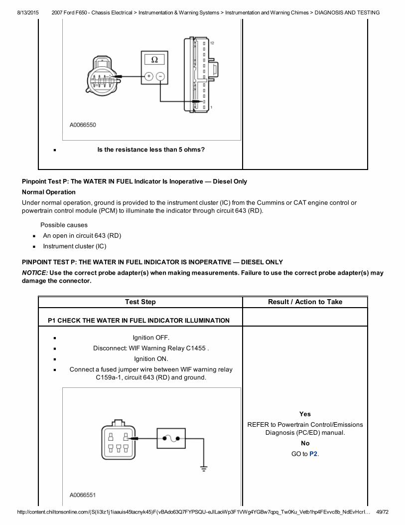
Pinpoint Test P: The WATER IN FUEL Indicator Is Inoperative — Diesel OnlyNormal OperationUnder normal operation, ground is provided to the instrument cluster (IC) from the Cummins or CAT engine control orpowertrain control module (PCM) to illuminate the indicator through circuit 643 (RD).
Possible causes
An open in circuit 643 (RD)
Instrument cluster (IC)
PINPOINT TEST P: THE WATER IN FUEL INDICATOR IS INOPERATIVE — DIESEL ONLYNOTICE: Use the correct probe adapter(s) when making measurements. Failure to use the correct probe adapter(s) maydamage the connector.
Test Step Result / Action to Take
P1 CHECK THE WATER IN FUEL INDICATOR ILLUMINATION
Ignition OFF.
Disconnect: WIF Warning Relay C1455 .
Ignition ON.
Connect a fused jumper wire between WIF warning relayC159a1, circuit 643 (RD) and ground.
YesREFER to Powertrain Control/Emissions
Diagnosis (PC/ED) manual.
NoGO to P2.
8/13/2015 2007 Ford F650 Chassis Electrical > Instrumentation & Warning Systems > Instrumentation and Warning Chimes > DIAGNOSIS AND TESTING
http://content.chiltonsonline.com/(S(li3lz1j1iaauis45tacnyk45)F(vBAdo63Q7FYPSQUeJlLaoWp3F1VWg4YGBw7qpq_Tw0Ku_Vetb1hp4FEvvc8b_NdEvHcrI… 50/72
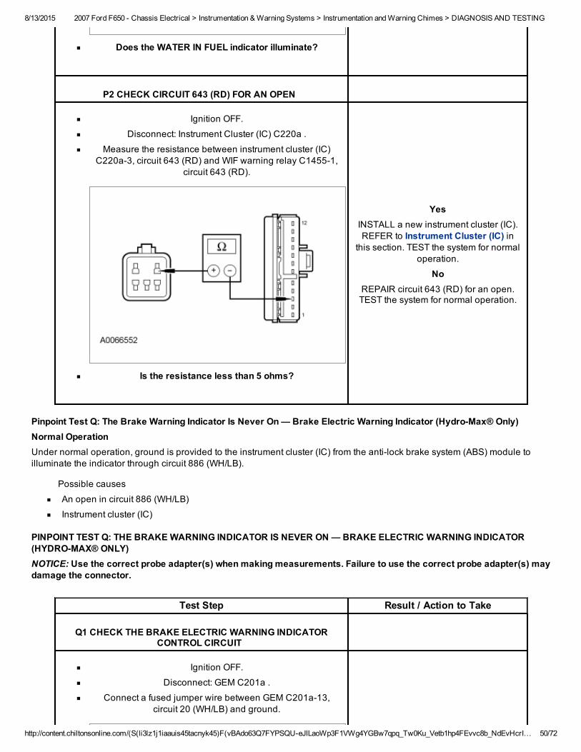
Does the WATER IN FUEL indicator illuminate?
P2 CHECK CIRCUIT 643 (RD) FOR AN OPEN
Ignition OFF.
Disconnect: Instrument Cluster (IC) C220a .
Measure the resistance between instrument cluster (IC)C220a3, circuit 643 (RD) and WIF warning relay C14551,
circuit 643 (RD).
Is the resistance less than 5 ohms?
YesINSTALL a new instrument cluster (IC).REFER to Instrument Cluster (IC) in
this section. TEST the system for normaloperation.
NoREPAIR circuit 643 (RD) for an open.TEST the system for normal operation.
Pinpoint Test Q: The Brake Warning Indicator Is Never On — Brake Electric Warning Indicator (HydroMax® Only)Normal OperationUnder normal operation, ground is provided to the instrument cluster (IC) from the antilock brake system (ABS) module toilluminate the indicator through circuit 886 (WH/LB).
Possible causes
An open in circuit 886 (WH/LB)
Instrument cluster (IC)
PINPOINT TEST Q: THE BRAKE WARNING INDICATOR IS NEVER ON — BRAKE ELECTRIC WARNING INDICATOR(HYDROMAX® ONLY)NOTICE: Use the correct probe adapter(s) when making measurements. Failure to use the correct probe adapter(s) maydamage the connector.
Test Step Result / Action to Take
Q1 CHECK THE BRAKE ELECTRIC WARNING INDICATORCONTROL CIRCUIT
Ignition OFF.
Disconnect: GEM C201a .
Connect a fused jumper wire between GEM C201a13,circuit 20 (WH/LB) and ground.
8/13/2015 2007 Ford F650 Chassis Electrical > Instrumentation & Warning Systems > Instrumentation and Warning Chimes > DIAGNOSIS AND TESTING
http://content.chiltonsonline.com/(S(li3lz1j1iaauis45tacnyk45)F(vBAdo63Q7FYPSQUeJlLaoWp3F1VWg4YGBw7qpq_Tw0Ku_Vetb1hp4FEvvc8b_NdEvHcrI… 51/72
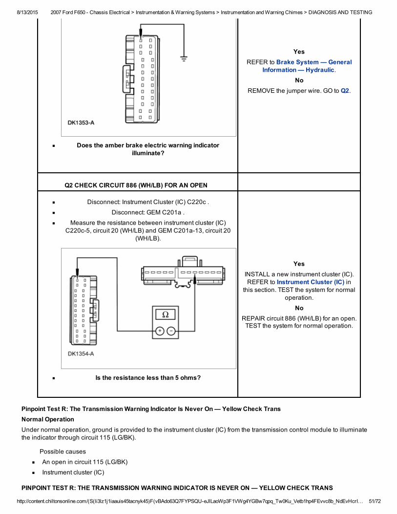
Does the amber brake electric warning indicatorilluminate?
YesREFER to Brake System — General
Information — Hydraulic.No
REMOVE the jumper wire. GO to Q2.
Q2 CHECK CIRCUIT 886 (WH/LB) FOR AN OPEN
Disconnect: Instrument Cluster (IC) C220c .
Disconnect: GEM C201a .
Measure the resistance between instrument cluster (IC)C220c5, circuit 20 (WH/LB) and GEM C201a13, circuit 20
(WH/LB).
Is the resistance less than 5 ohms?
YesINSTALL a new instrument cluster (IC).REFER to Instrument Cluster (IC) in
this section. TEST the system for normaloperation.
NoREPAIR circuit 886 (WH/LB) for an open.TEST the system for normal operation.
Pinpoint Test R: The Transmission Warning Indicator Is Never On — Yellow Check TransNormal OperationUnder normal operation, ground is provided to the instrument cluster (IC) from the transmission control module to illuminatethe indicator through circuit 115 (LG/BK).
Possible causes
An open in circuit 115 (LG/BK)
Instrument cluster (IC)
PINPOINT TEST R: THE TRANSMISSION WARNING INDICATOR IS NEVER ON — YELLOW CHECK TRANS
8/13/2015 2007 Ford F650 Chassis Electrical > Instrumentation & Warning Systems > Instrumentation and Warning Chimes > DIAGNOSIS AND TESTING
http://content.chiltonsonline.com/(S(li3lz1j1iaauis45tacnyk45)F(vBAdo63Q7FYPSQUeJlLaoWp3F1VWg4YGBw7qpq_Tw0Ku_Vetb1hp4FEvvc8b_NdEvHcrI… 52/72
NOTICE: Use the correct probe adapter(s) when making measurements. Failure to use the correct probe adapter(s) maydamage the connector.
Test Step Result / Action to Take
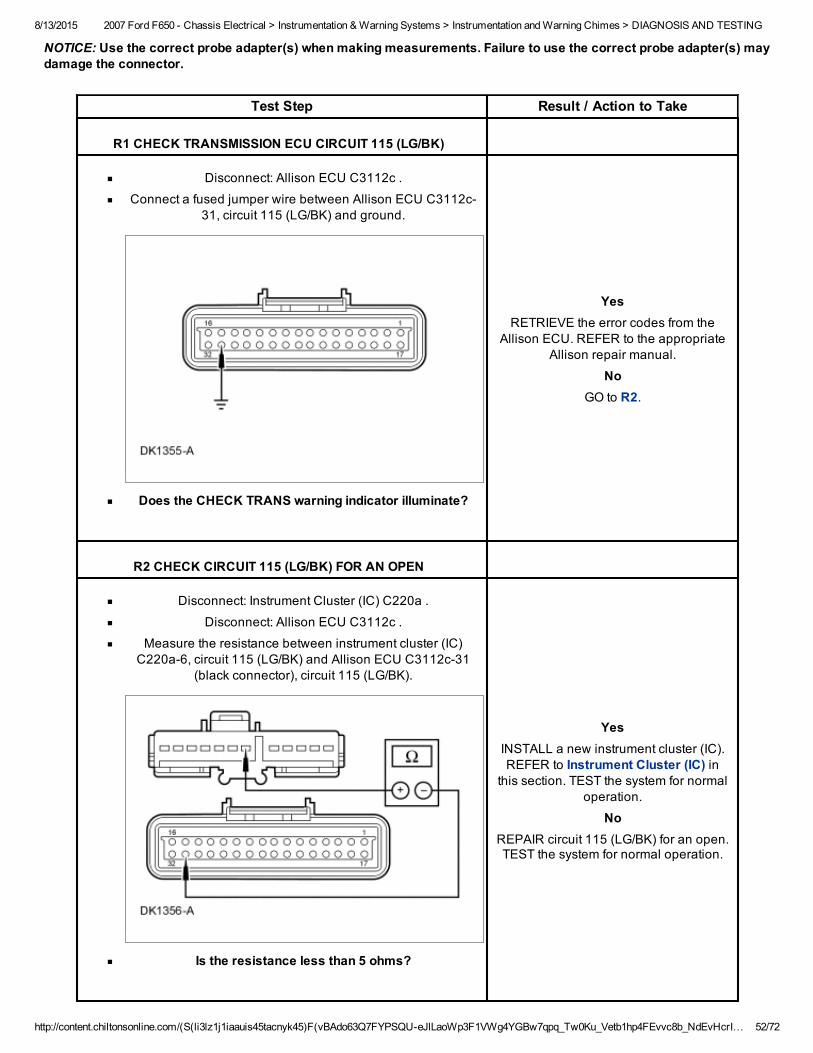
R1 CHECK TRANSMISSION ECU CIRCUIT 115 (LG/BK)
Disconnect: Allison ECU C3112c .
Connect a fused jumper wire between Allison ECU C3112c31, circuit 115 (LG/BK) and ground.
Does the CHECK TRANS warning indicator illuminate?
YesRETRIEVE the error codes from the
Allison ECU. REFER to the appropriateAllison repair manual.
NoGO to R2.
R2 CHECK CIRCUIT 115 (LG/BK) FOR AN OPEN
Disconnect: Instrument Cluster (IC) C220a .
Disconnect: Allison ECU C3112c .
Measure the resistance between instrument cluster (IC)C220a6, circuit 115 (LG/BK) and Allison ECU C3112c31
(black connector), circuit 115 (LG/BK).
Is the resistance less than 5 ohms?
YesINSTALL a new instrument cluster (IC).REFER to Instrument Cluster (IC) in
this section. TEST the system for normaloperation.
NoREPAIR circuit 115 (LG/BK) for an open.TEST the system for normal operation.
8/13/2015 2007 Ford F650 Chassis Electrical > Instrumentation & Warning Systems > Instrumentation and Warning Chimes > DIAGNOSIS AND TESTING
http://content.chiltonsonline.com/(S(li3lz1j1iaauis45tacnyk45)F(vBAdo63Q7FYPSQUeJlLaoWp3F1VWg4YGBw7qpq_Tw0Ku_Vetb1hp4FEvvc8b_NdEvHcrI… 53/72
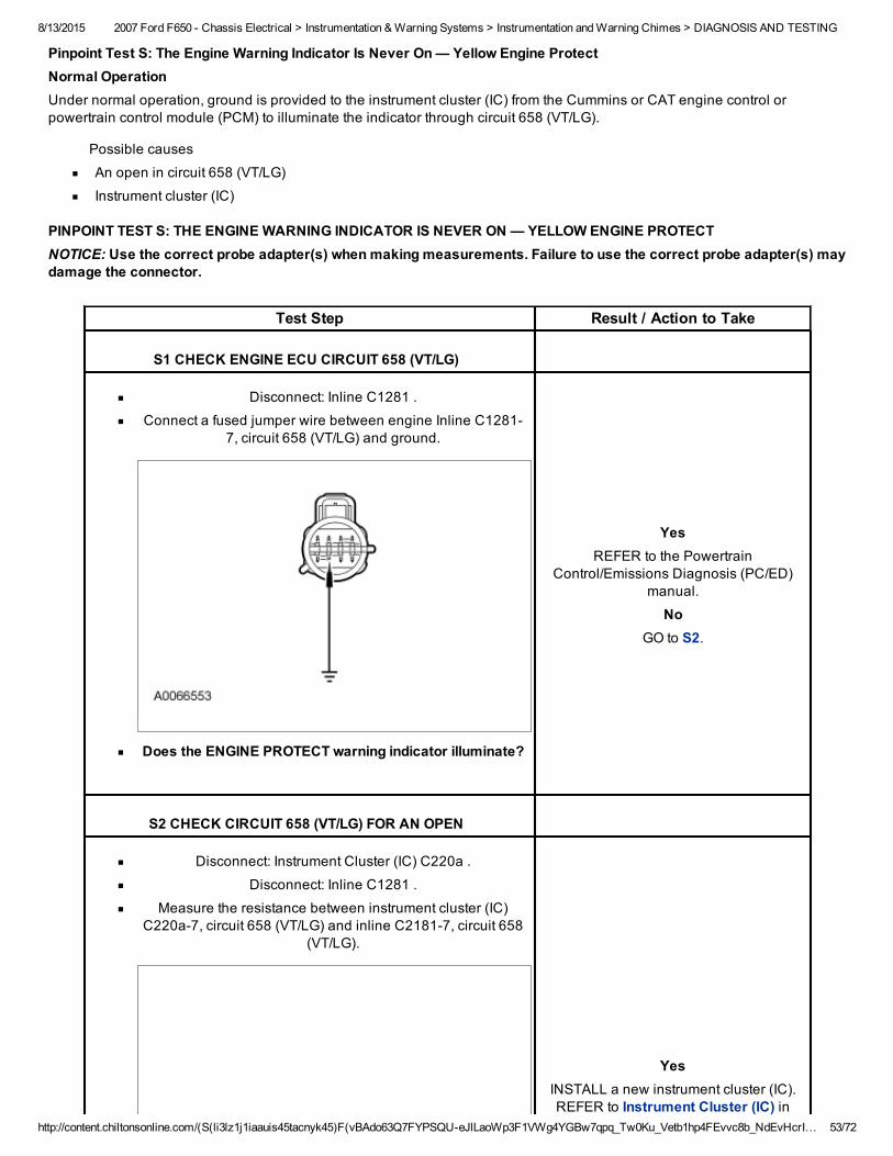
Pinpoint Test S: The Engine Warning Indicator Is Never On — Yellow Engine ProtectNormal OperationUnder normal operation, ground is provided to the instrument cluster (IC) from the Cummins or CAT engine control orpowertrain control module (PCM) to illuminate the indicator through circuit 658 (VT/LG).
Possible causes
An open in circuit 658 (VT/LG)
Instrument cluster (IC)
PINPOINT TEST S: THE ENGINE WARNING INDICATOR IS NEVER ON — YELLOW ENGINE PROTECTNOTICE: Use the correct probe adapter(s) when making measurements. Failure to use the correct probe adapter(s) maydamage the connector.
Test Step Result / Action to Take
S1 CHECK ENGINE ECU CIRCUIT 658 (VT/LG)
Disconnect: Inline C1281 .
Connect a fused jumper wire between engine Inline C12817, circuit 658 (VT/LG) and ground.
Does the ENGINE PROTECT warning indicator illuminate?
YesREFER to the Powertrain
Control/Emissions Diagnosis (PC/ED)manual.
NoGO to S2.
S2 CHECK CIRCUIT 658 (VT/LG) FOR AN OPEN
Disconnect: Instrument Cluster (IC) C220a .
Disconnect: Inline C1281 .
Measure the resistance between instrument cluster (IC)C220a7, circuit 658 (VT/LG) and inline C21817, circuit 658
(VT/LG).
YesINSTALL a new instrument cluster (IC).REFER to Instrument Cluster (IC) in
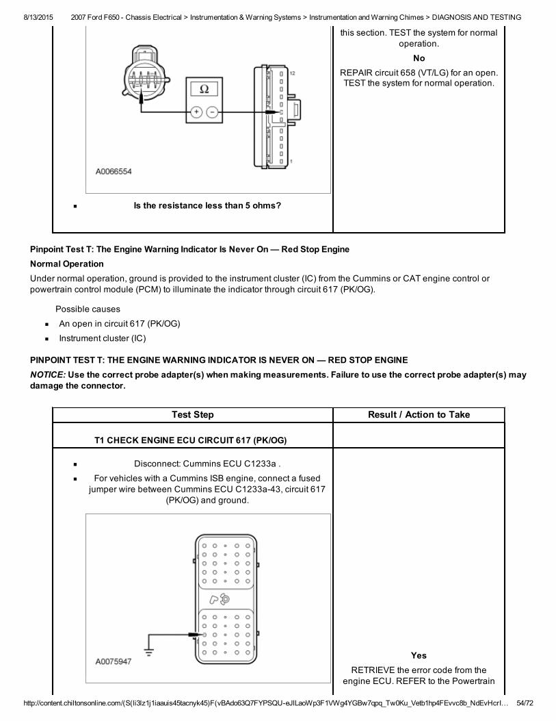
8/13/2015 2007 Ford F650 Chassis Electrical > Instrumentation & Warning Systems > Instrumentation and Warning Chimes > DIAGNOSIS AND TESTING
http://content.chiltonsonline.com/(S(li3lz1j1iaauis45tacnyk45)F(vBAdo63Q7FYPSQUeJlLaoWp3F1VWg4YGBw7qpq_Tw0Ku_Vetb1hp4FEvvc8b_NdEvHcrI… 54/72
Is the resistance less than 5 ohms?
this section. TEST the system for normaloperation.
NoREPAIR circuit 658 (VT/LG) for an open.TEST the system for normal operation.
Pinpoint Test T: The Engine Warning Indicator Is Never On — Red Stop EngineNormal OperationUnder normal operation, ground is provided to the instrument cluster (IC) from the Cummins or CAT engine control orpowertrain control module (PCM) to illuminate the indicator through circuit 617 (PK/OG).
Possible causes
An open in circuit 617 (PK/OG)
Instrument cluster (IC)
PINPOINT TEST T: THE ENGINE WARNING INDICATOR IS NEVER ON — RED STOP ENGINENOTICE: Use the correct probe adapter(s) when making measurements. Failure to use the correct probe adapter(s) maydamage the connector.
Test Step Result / Action to Take
T1 CHECK ENGINE ECU CIRCUIT 617 (PK/OG)
Disconnect: Cummins ECU C1233a .
For vehicles with a Cummins ISB engine, connect a fusedjumper wire between Cummins ECU C1233a43, circuit 617
(PK/OG) and ground.
YesRETRIEVE the error code from the
engine ECU. REFER to the Powertrain
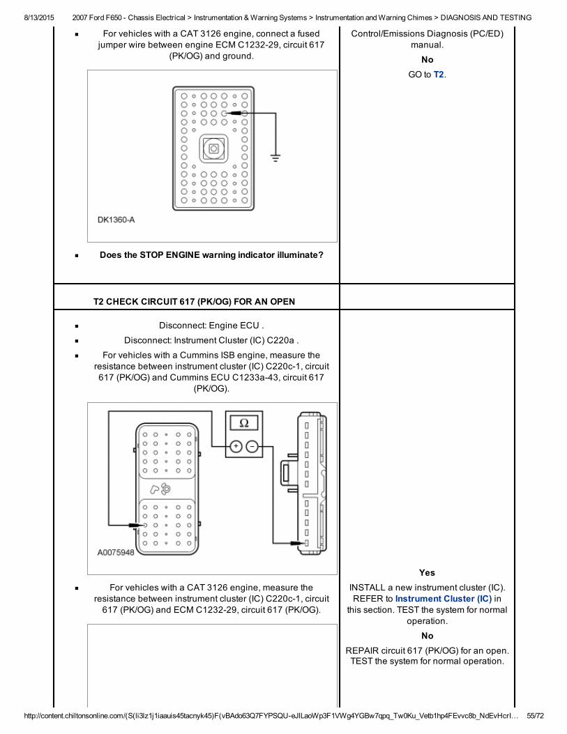
8/13/2015 2007 Ford F650 Chassis Electrical > Instrumentation & Warning Systems > Instrumentation and Warning Chimes > DIAGNOSIS AND TESTING
http://content.chiltonsonline.com/(S(li3lz1j1iaauis45tacnyk45)F(vBAdo63Q7FYPSQUeJlLaoWp3F1VWg4YGBw7qpq_Tw0Ku_Vetb1hp4FEvvc8b_NdEvHcrI… 55/72
For vehicles with a CAT 3126 engine, connect a fusedjumper wire between engine ECM C123229, circuit 617
(PK/OG) and ground.
Does the STOP ENGINE warning indicator illuminate?
Control/Emissions Diagnosis (PC/ED)manual.
NoGO to T2.
T2 CHECK CIRCUIT 617 (PK/OG) FOR AN OPEN
Disconnect: Engine ECU .
Disconnect: Instrument Cluster (IC) C220a .
For vehicles with a Cummins ISB engine, measure theresistance between instrument cluster (IC) C220c1, circuit617 (PK/OG) and Cummins ECU C1233a43, circuit 617
(PK/OG).
For vehicles with a CAT 3126 engine, measure theresistance between instrument cluster (IC) C220c1, circuit617 (PK/OG) and ECM C123229, circuit 617 (PK/OG).
YesINSTALL a new instrument cluster (IC).REFER to Instrument Cluster (IC) in
this section. TEST the system for normaloperation.
NoREPAIR circuit 617 (PK/OG) for an open.TEST the system for normal operation.
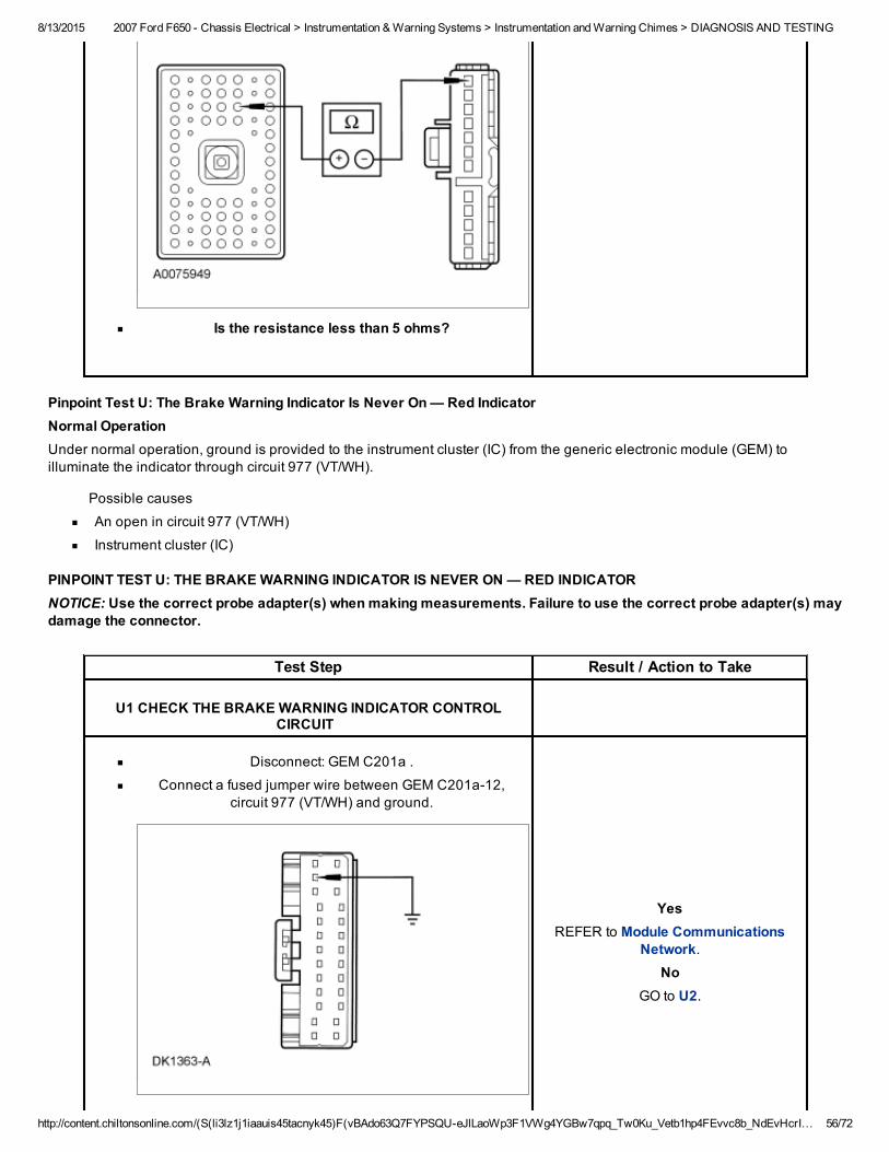
8/13/2015 2007 Ford F650 Chassis Electrical > Instrumentation & Warning Systems > Instrumentation and Warning Chimes > DIAGNOSIS AND TESTING
http://content.chiltonsonline.com/(S(li3lz1j1iaauis45tacnyk45)F(vBAdo63Q7FYPSQUeJlLaoWp3F1VWg4YGBw7qpq_Tw0Ku_Vetb1hp4FEvvc8b_NdEvHcrI… 56/72
Is the resistance less than 5 ohms?
Pinpoint Test U: The Brake Warning Indicator Is Never On — Red IndicatorNormal OperationUnder normal operation, ground is provided to the instrument cluster (IC) from the generic electronic module (GEM) toilluminate the indicator through circuit 977 (VT/WH).
Possible causes
An open in circuit 977 (VT/WH)
Instrument cluster (IC)
PINPOINT TEST U: THE BRAKE WARNING INDICATOR IS NEVER ON — RED INDICATORNOTICE: Use the correct probe adapter(s) when making measurements. Failure to use the correct probe adapter(s) maydamage the connector.
Test Step Result / Action to Take
U1 CHECK THE BRAKE WARNING INDICATOR CONTROLCIRCUIT
Disconnect: GEM C201a .
Connect a fused jumper wire between GEM C201a12,circuit 977 (VT/WH) and ground.
YesREFER to Module Communications
Network.No
GO to U2.
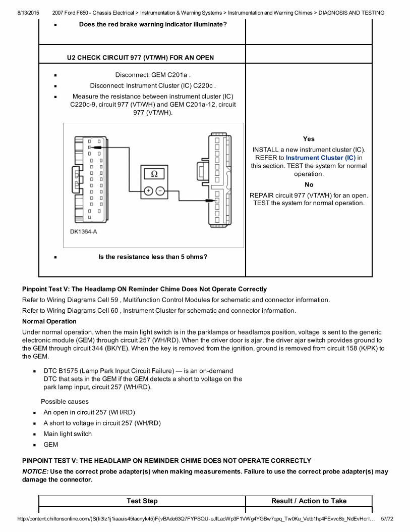
8/13/2015 2007 Ford F650 Chassis Electrical > Instrumentation & Warning Systems > Instrumentation and Warning Chimes > DIAGNOSIS AND TESTING
http://content.chiltonsonline.com/(S(li3lz1j1iaauis45tacnyk45)F(vBAdo63Q7FYPSQUeJlLaoWp3F1VWg4YGBw7qpq_Tw0Ku_Vetb1hp4FEvvc8b_NdEvHcrI… 57/72
Does the red brake warning indicator illuminate?
U2 CHECK CIRCUIT 977 (VT/WH) FOR AN OPEN
Disconnect: GEM C201a .
Disconnect: Instrument Cluster (IC) C220c .
Measure the resistance between instrument cluster (IC)C220c9, circuit 977 (VT/WH) and GEM C201a12, circuit
977 (VT/WH).
Is the resistance less than 5 ohms?
YesINSTALL a new instrument cluster (IC).REFER to Instrument Cluster (IC) in
this section. TEST the system for normaloperation.
NoREPAIR circuit 977 (VT/WH) for an open.TEST the system for normal operation.
Pinpoint Test V: The Headlamp ON Reminder Chime Does Not Operate CorrectlyRefer to Wiring Diagrams Cell 59 , Multifunction Control Modules for schematic and connector information.
Refer to Wiring Diagrams Cell 60 , Instrument Cluster for schematic and connector information.
Normal OperationUnder normal operation, when the main light switch is in the parklamps or headlamps position, voltage is sent to the genericelectronic module (GEM) through circuit 257 (WH/RD). When the driver door is ajar, the driver ajar switch provides ground tothe GEM through circuit 344 (BK/YE). When the key is removed from the ignition, ground is removed from circuit 158 (K/PK) tothe GEM.
DTC B1575 (Lamp Park Input Circuit Failure) — is an ondemandDTC that sets in the GEM if the GEM detects a short to voltage on thepark lamp input, circuit 257 (WH/RD).
Possible causes
An open in circuit 257 (WH/RD)
A short to voltage in circuit 257 (WH/RD)
Main light switch
GEM
PINPOINT TEST V: THE HEADLAMP ON REMINDER CHIME DOES NOT OPERATE CORRECTLYNOTICE: Use the correct probe adapter(s) when making measurements. Failure to use the correct probe adapter(s) maydamage the connector.
Test Step Result / Action to Take
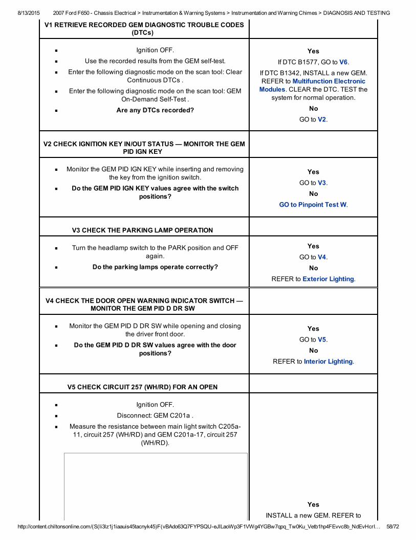
8/13/2015 2007 Ford F650 Chassis Electrical > Instrumentation & Warning Systems > Instrumentation and Warning Chimes > DIAGNOSIS AND TESTING
http://content.chiltonsonline.com/(S(li3lz1j1iaauis45tacnyk45)F(vBAdo63Q7FYPSQUeJlLaoWp3F1VWg4YGBw7qpq_Tw0Ku_Vetb1hp4FEvvc8b_NdEvHcrI… 58/72
V1 RETRIEVE RECORDED GEM DIAGNOSTIC TROUBLE CODES(DTCs)
Ignition OFF.
Use the recorded results from the GEM selftest.
Enter the following diagnostic mode on the scan tool: ClearContinuous DTCs .
Enter the following diagnostic mode on the scan tool: GEMOnDemand SelfTest .
Are any DTCs recorded?
YesIf DTC B1577, GO to V6.
If DTC B1342, INSTALL a new GEM.REFER to Multifunction ElectronicModules. CLEAR the DTC. TEST the
system for normal operation.
NoGO to V2.
V2 CHECK IGNITION KEY IN/OUT STATUS — MONITOR THE GEMPID IGN KEY
Monitor the GEM PID IGN KEY while inserting and removingthe key from the ignition switch.
Do the GEM PID IGN KEY values agree with the switchpositions?
YesGO to V3.
NoGO to Pinpoint Test W.
V3 CHECK THE PARKING LAMP OPERATION
Turn the headlamp switch to the PARK position and OFFagain.
Do the parking lamps operate correctly?
YesGO to V4.
NoREFER to Exterior Lighting.
V4 CHECK THE DOOR OPEN WARNING INDICATOR SWITCH —MONITOR THE GEM PID D DR SW
Monitor the GEM PID D DR SW while opening and closingthe driver front door.
Do the GEM PID D DR SW values agree with the doorpositions?
YesGO to V5.
NoREFER to Interior Lighting.
V5 CHECK CIRCUIT 257 (WH/RD) FOR AN OPEN
Ignition OFF.
Disconnect: GEM C201a .
Measure the resistance between main light switch C205a11, circuit 257 (WH/RD) and GEM C201a17, circuit 257
(WH/RD).
YesINSTALL a new GEM. REFER to
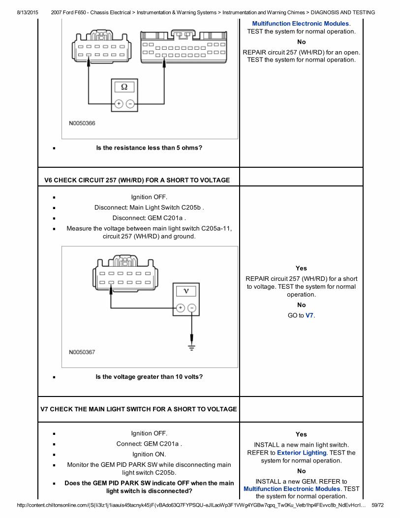
8/13/2015 2007 Ford F650 Chassis Electrical > Instrumentation & Warning Systems > Instrumentation and Warning Chimes > DIAGNOSIS AND TESTING
http://content.chiltonsonline.com/(S(li3lz1j1iaauis45tacnyk45)F(vBAdo63Q7FYPSQUeJlLaoWp3F1VWg4YGBw7qpq_Tw0Ku_Vetb1hp4FEvvc8b_NdEvHcrI… 59/72
Is the resistance less than 5 ohms?
Multifunction Electronic Modules.TEST the system for normal operation.
NoREPAIR circuit 257 (WH/RD) for an open.TEST the system for normal operation.
V6 CHECK CIRCUIT 257 (WH/RD) FOR A SHORT TO VOLTAGE
Ignition OFF.
Disconnect: Main Light Switch C205b .
Disconnect: GEM C201a .
Measure the voltage between main light switch C205a11,circuit 257 (WH/RD) and ground.
Is the voltage greater than 10 volts?
YesREPAIR circuit 257 (WH/RD) for a shortto voltage. TEST the system for normal
operation.
NoGO to V7.
V7 CHECK THE MAIN LIGHT SWITCH FOR A SHORT TO VOLTAGE
Ignition OFF.
Connect: GEM C201a .
Ignition ON.
Monitor the GEM PID PARK SW while disconnecting mainlight switch C205b.
Does the GEM PID PARK SW indicate OFF when the mainlight switch is disconnected?
YesINSTALL a new main light switch.
REFER to Exterior Lighting. TEST thesystem for normal operation.
NoINSTALL a new GEM. REFER to
Multifunction Electronic Modules. TESTthe system for normal operation.
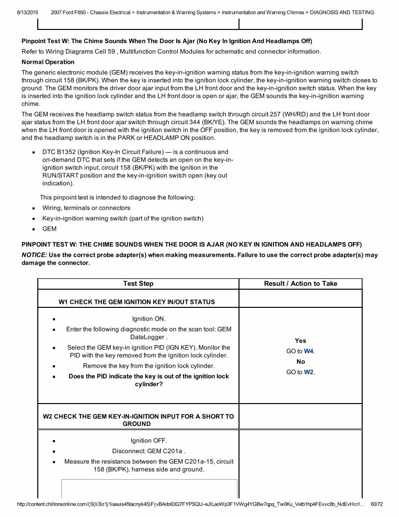
8/13/2015 2007 Ford F650 Chassis Electrical > Instrumentation & Warning Systems > Instrumentation and Warning Chimes > DIAGNOSIS AND TESTING
http://content.chiltonsonline.com/(S(li3lz1j1iaauis45tacnyk45)F(vBAdo63Q7FYPSQUeJlLaoWp3F1VWg4YGBw7qpq_Tw0Ku_Vetb1hp4FEvvc8b_NdEvHcrI… 60/72
Pinpoint Test W: The Chime Sounds When The Door Is Ajar (No Key In Ignition And Headlamps Off)Refer to Wiring Diagrams Cell 59 , Multifunction Control Modules for schematic and connector information.
Normal OperationThe generic electronic module (GEM) receives the keyinignition warning status from the keyinignition warning switchthrough circuit 158 (BK/PK). When the key is inserted into the ignition lock cylinder, the keyinignition warning switch closes toground. The GEM monitors the driver door ajar input from the LH front door and the keyinignition switch status. When the keyis inserted into the ignition lock cylinder and the LH front door is open or ajar, the GEM sounds the keyinignition warningchime.
The GEM receives the headlamp switch status from the headlamp switch through circuit 257 (WH/RD) and the LH front doorajar status from the LH front door ajar switch through circuit 344 (BK/YE). The GEM sounds the headlamps on warning chimewhen the LH front door is opened with the ignition switch in the OFF position, the key is removed from the ignition lock cylinder,and the headlamp switch is in the PARK or HEADLAMP ON position.
DTC B1352 (Ignition KeyIn Circuit Failure) — is a continuous andondemand DTC that sets if the GEM detects an open on the keyinignition switch input, circuit 158 (BK/PK) with the ignition in theRUN/START position and the keyinignition switch open (key outindication).
This pinpoint test is intended to diagnose the following:
Wiring, terminals or connectors
Keyinignition warning switch (part of the ignition switch)
GEM
PINPOINT TEST W: THE CHIME SOUNDS WHEN THE DOOR IS AJAR (NO KEY IN IGNITION AND HEADLAMPS OFF)NOTICE: Use the correct probe adapter(s) when making measurements. Failure to use the correct probe adapter(s) maydamage the connector.
Test Step Result / Action to Take
W1 CHECK THE GEM IGNITION KEY IN/OUT STATUS
Ignition ON.
Enter the following diagnostic mode on the scan tool: GEMDataLogger .
Select the GEM keyin ignition PID (IGN KEY). Monitor thePID with the key removed from the ignition lock cylinder.
Remove the key from the ignition lock cylinder.
Does the PID indicate the key is out of the ignition lockcylinder?
YesGO to W4.
NoGO to W2.
W2 CHECK THE GEM KEYINIGNITION INPUT FOR A SHORT TOGROUND
Ignition OFF.
Disconnect: GEM C201a .
Measure the resistance between the GEM C201a15, circuit158 (BK/PK), harness side and ground.
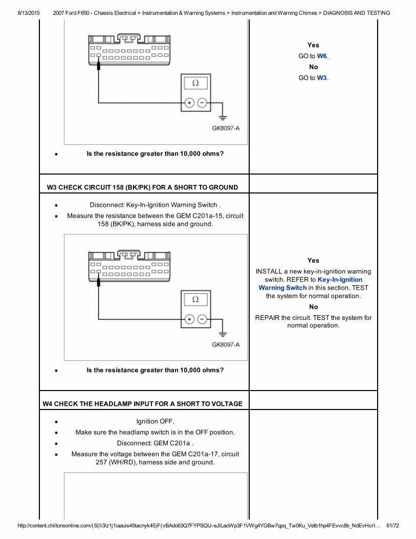
8/13/2015 2007 Ford F650 Chassis Electrical > Instrumentation & Warning Systems > Instrumentation and Warning Chimes > DIAGNOSIS AND TESTING
http://content.chiltonsonline.com/(S(li3lz1j1iaauis45tacnyk45)F(vBAdo63Q7FYPSQUeJlLaoWp3F1VWg4YGBw7qpq_Tw0Ku_Vetb1hp4FEvvc8b_NdEvHcrI… 61/72
Is the resistance greater than 10,000 ohms?
YesGO to W6.
NoGO to W3.
W3 CHECK CIRCUIT 158 (BK/PK) FOR A SHORT TO GROUND
Disconnect: KeyInIgnition Warning Switch .
Measure the resistance between the GEM C201a15, circuit158 (BK/PK), harness side and ground.
Is the resistance greater than 10,000 ohms?
YesINSTALL a new keyinignition warning
switch. REFER to KeyInIgnitionWarning Switch in this section. TESTthe system for normal operation.
NoREPAIR the circuit. TEST the system for
normal operation.
W4 CHECK THE HEADLAMP INPUT FOR A SHORT TO VOLTAGE
Ignition OFF.
Make sure the headlamp switch is in the OFF position.
Disconnect: GEM C201a .
Measure the voltage between the GEM C201a17, circuit257 (WH/RD), harness side and ground.
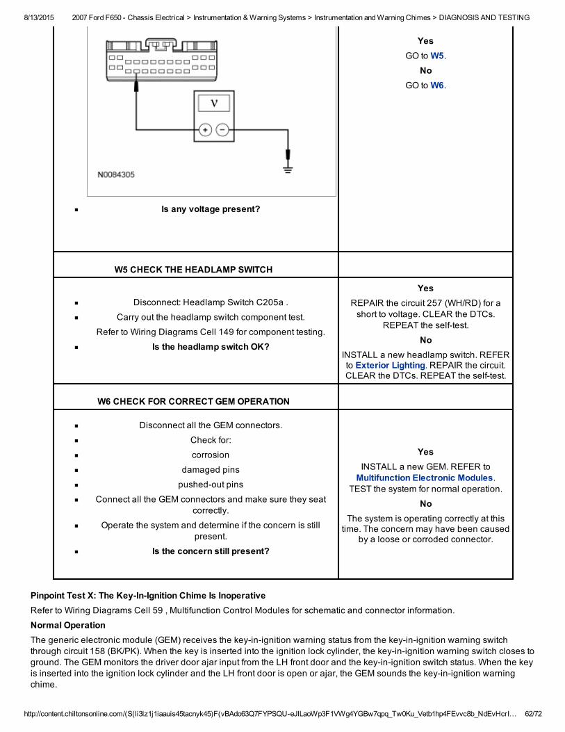
8/13/2015 2007 Ford F650 Chassis Electrical > Instrumentation & Warning Systems > Instrumentation and Warning Chimes > DIAGNOSIS AND TESTING
http://content.chiltonsonline.com/(S(li3lz1j1iaauis45tacnyk45)F(vBAdo63Q7FYPSQUeJlLaoWp3F1VWg4YGBw7qpq_Tw0Ku_Vetb1hp4FEvvc8b_NdEvHcrI… 62/72
Is any voltage present?
YesGO to W5.
NoGO to W6.
W5 CHECK THE HEADLAMP SWITCH
Disconnect: Headlamp Switch C205a .
Carry out the headlamp switch component test.
Refer to Wiring Diagrams Cell 149 for component testing.
Is the headlamp switch OK?
YesREPAIR the circuit 257 (WH/RD) for ashort to voltage. CLEAR the DTCs.
REPEAT the selftest.
NoINSTALL a new headlamp switch. REFERto Exterior Lighting. REPAIR the circuit.CLEAR the DTCs. REPEAT the selftest.
W6 CHECK FOR CORRECT GEM OPERATION
Disconnect all the GEM connectors.
Check for:
corrosion
damaged pins
pushedout pins
Connect all the GEM connectors and make sure they seatcorrectly.
Operate the system and determine if the concern is stillpresent.
Is the concern still present?
YesINSTALL a new GEM. REFER toMultifunction Electronic Modules.
TEST the system for normal operation.
NoThe system is operating correctly at thistime. The concern may have been caused
by a loose or corroded connector.
Pinpoint Test X: The KeyInIgnition Chime Is InoperativeRefer to Wiring Diagrams Cell 59 , Multifunction Control Modules for schematic and connector information.
Normal OperationThe generic electronic module (GEM) receives the keyinignition warning status from the keyinignition warning switchthrough circuit 158 (BK/PK). When the key is inserted into the ignition lock cylinder, the keyinignition warning switch closes toground. The GEM monitors the driver door ajar input from the LH front door and the keyinignition switch status. When the keyis inserted into the ignition lock cylinder and the LH front door is open or ajar, the GEM sounds the keyinignition warningchime.
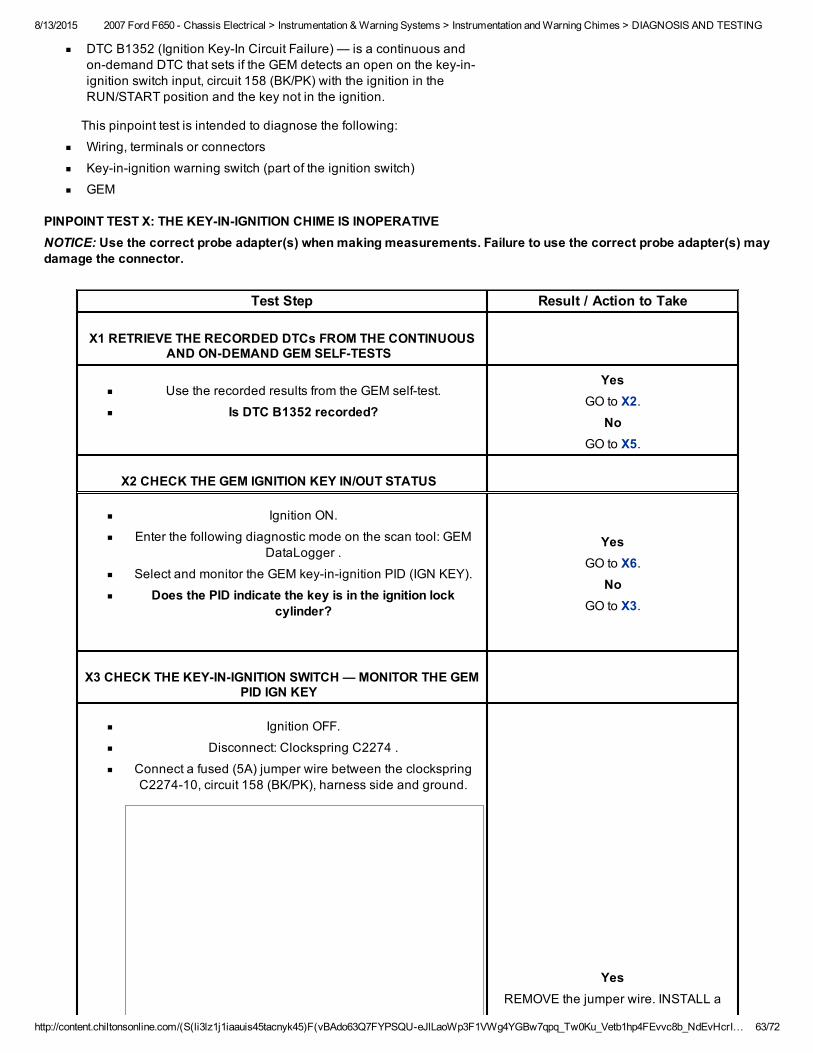
8/13/2015 2007 Ford F650 Chassis Electrical > Instrumentation & Warning Systems > Instrumentation and Warning Chimes > DIAGNOSIS AND TESTING
http://content.chiltonsonline.com/(S(li3lz1j1iaauis45tacnyk45)F(vBAdo63Q7FYPSQUeJlLaoWp3F1VWg4YGBw7qpq_Tw0Ku_Vetb1hp4FEvvc8b_NdEvHcrI… 63/72
DTC B1352 (Ignition KeyIn Circuit Failure) — is a continuous andondemand DTC that sets if the GEM detects an open on the keyinignition switch input, circuit 158 (BK/PK) with the ignition in theRUN/START position and the key not in the ignition.
This pinpoint test is intended to diagnose the following:
Wiring, terminals or connectors
Keyinignition warning switch (part of the ignition switch)
GEM
PINPOINT TEST X: THE KEYINIGNITION CHIME IS INOPERATIVENOTICE: Use the correct probe adapter(s) when making measurements. Failure to use the correct probe adapter(s) maydamage the connector.
Test Step Result / Action to Take
X1 RETRIEVE THE RECORDED DTCs FROM THE CONTINUOUSAND ONDEMAND GEM SELFTESTS
Use the recorded results from the GEM selftest.
Is DTC B1352 recorded?
YesGO to X2.
NoGO to X5.
X2 CHECK THE GEM IGNITION KEY IN/OUT STATUS
Ignition ON.
Enter the following diagnostic mode on the scan tool: GEMDataLogger .
Select and monitor the GEM keyinignition PID (IGN KEY).
Does the PID indicate the key is in the ignition lockcylinder?
YesGO to X6.
NoGO to X3.
X3 CHECK THE KEYINIGNITION SWITCH — MONITOR THE GEMPID IGN KEY
Ignition OFF.
Disconnect: Clockspring C2274 .
Connect a fused (5A) jumper wire between the clockspringC227410, circuit 158 (BK/PK), harness side and ground.
YesREMOVE the jumper wire. INSTALL a
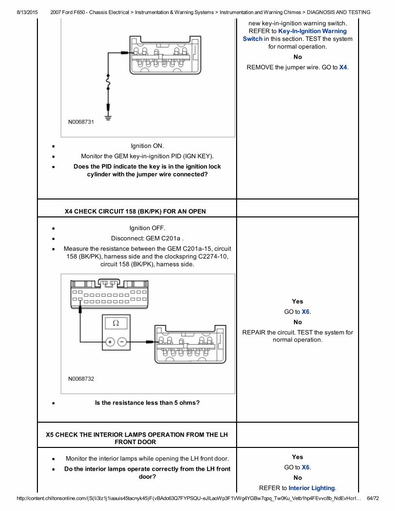
8/13/2015 2007 Ford F650 Chassis Electrical > Instrumentation & Warning Systems > Instrumentation and Warning Chimes > DIAGNOSIS AND TESTING
http://content.chiltonsonline.com/(S(li3lz1j1iaauis45tacnyk45)F(vBAdo63Q7FYPSQUeJlLaoWp3F1VWg4YGBw7qpq_Tw0Ku_Vetb1hp4FEvvc8b_NdEvHcrI… 64/72
Ignition ON.
Monitor the GEM keyinignition PID (IGN KEY).
Does the PID indicate the key is in the ignition lockcylinder with the jumper wire connected?
new keyinignition warning switch.REFER to KeyInIgnition Warning
Switch in this section. TEST the systemfor normal operation.
NoREMOVE the jumper wire. GO to X4.
X4 CHECK CIRCUIT 158 (BK/PK) FOR AN OPEN
Ignition OFF.
Disconnect: GEM C201a .
Measure the resistance between the GEM C201a15, circuit158 (BK/PK), harness side and the clockspring C227410,
circuit 158 (BK/PK), harness side.
Is the resistance less than 5 ohms?
YesGO to X6.
NoREPAIR the circuit. TEST the system for
normal operation.
X5 CHECK THE INTERIOR LAMPS OPERATION FROM THE LHFRONT DOOR
Monitor the interior lamps while opening the LH front door.
Do the interior lamps operate correctly from the LH frontdoor?
YesGO to X6.
NoREFER to Interior Lighting.
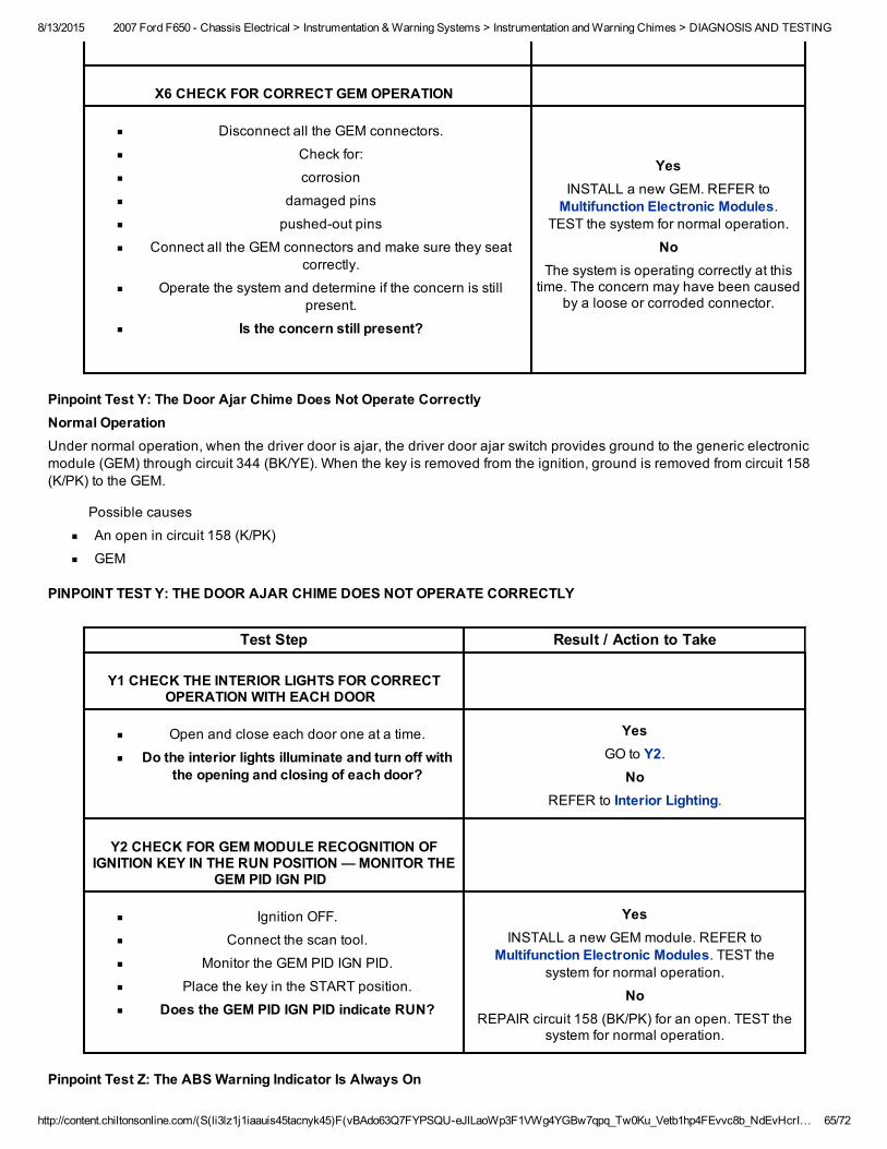
8/13/2015 2007 Ford F650 Chassis Electrical > Instrumentation & Warning Systems > Instrumentation and Warning Chimes > DIAGNOSIS AND TESTING
http://content.chiltonsonline.com/(S(li3lz1j1iaauis45tacnyk45)F(vBAdo63Q7FYPSQUeJlLaoWp3F1VWg4YGBw7qpq_Tw0Ku_Vetb1hp4FEvvc8b_NdEvHcrI… 65/72
X6 CHECK FOR CORRECT GEM OPERATION
Disconnect all the GEM connectors.
Check for:
corrosion
damaged pins
pushedout pins
Connect all the GEM connectors and make sure they seatcorrectly.
Operate the system and determine if the concern is stillpresent.
Is the concern still present?
YesINSTALL a new GEM. REFER toMultifunction Electronic Modules.
TEST the system for normal operation.
NoThe system is operating correctly at thistime. The concern may have been caused
by a loose or corroded connector.
Pinpoint Test Y: The Door Ajar Chime Does Not Operate CorrectlyNormal OperationUnder normal operation, when the driver door is ajar, the driver door ajar switch provides ground to the generic electronicmodule (GEM) through circuit 344 (BK/YE). When the key is removed from the ignition, ground is removed from circuit 158(K/PK) to the GEM.
Possible causes
An open in circuit 158 (K/PK)
GEM
PINPOINT TEST Y: THE DOOR AJAR CHIME DOES NOT OPERATE CORRECTLY
Test Step Result / Action to Take
Y1 CHECK THE INTERIOR LIGHTS FOR CORRECTOPERATION WITH EACH DOOR
Open and close each door one at a time.
Do the interior lights illuminate and turn off withthe opening and closing of each door?
YesGO to Y2.
NoREFER to Interior Lighting.
Y2 CHECK FOR GEM MODULE RECOGNITION OFIGNITION KEY IN THE RUN POSITION — MONITOR THE
GEM PID IGN PID
Ignition OFF.
Connect the scan tool.
Monitor the GEM PID IGN PID.
Place the key in the START position.
Does the GEM PID IGN PID indicate RUN?
YesINSTALL a new GEM module. REFER to
Multifunction Electronic Modules. TEST thesystem for normal operation.
NoREPAIR circuit 158 (BK/PK) for an open. TEST the
system for normal operation.
Pinpoint Test Z: The ABS Warning Indicator Is Always On
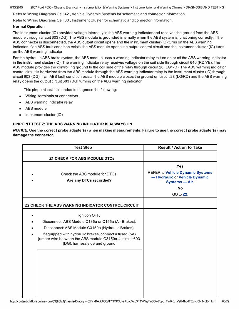
8/13/2015 2007 Ford F650 Chassis Electrical > Instrumentation & Warning Systems > Instrumentation and Warning Chimes > DIAGNOSIS AND TESTING
http://content.chiltonsonline.com/(S(li3lz1j1iaauis45tacnyk45)F(vBAdo63Q7FYPSQUeJlLaoWp3F1VWg4YGBw7qpq_Tw0Ku_Vetb1hp4FEvvc8b_NdEvHcrI… 66/72
Refer to Wiring Diagrams Cell 42 , Vehicle Dynamic Systems for schematic and connector information.
Refer to Wiring Diagrams Cell 60 , Instrument Cluster for schematic and connector information.
Normal OperationThe instrument cluster (IC) provides voltage internally to the ABS warning indicator and receives the ground from the ABSmodule through circuit 603 (DG). The ABS module is grounded internally when the ABS system is functioning correctly. If theABS connector is disconnected, the ABS output circuit opens and the instrument cluster (IC) turns on the ABS warningindicator. If an ABS fault condition exists, the ABS module opens the output control circuit and the instrument cluster (IC) turnson the ABS warning indicator.
For the hydraulic ABS brake system, the ABS module uses a warning indicator relay to turn on or off the ABS warning indicatorin the instrument cluster (IC). The warning indicator relay receives voltage on the coil side through circuit 640 (RD/YE). TheABS module provides the controlling ground to the coil side of the relay through circuit 28 (LG/RD). The ABS warning indicatorcontrol circuit is hardwired from the ABS module through the ABS warning indicator relay to the instrument cluster (IC) throughcircuit 603 (DG). If an ABS fault condition exists, the ABS module closes the ground on circuit 28 (LG/RD) and the ABS warningrelay opens the output circuit 603 (DG) turning on the ABS warning indicator.
This pinpoint test is intended to diagnose the following:
Wiring, terminals or connectors
ABS warning indicator relay
ABS module
Instrument cluster (IC)
PINPOINT TEST Z: THE ABS WARNING INDICATOR IS ALWAYS ONNOTICE: Use the correct probe adapter(s) when making measurements. Failure to use the correct probe adapter(s) maydamage the connector.
Test Step Result / Action to Take
Z1 CHECK FOR ABS MODULE DTCs
Check the ABS module for DTCs.
Are any DTCs recorded?
YesREFER to Vehicle Dynamic Systems— Hydraulic or Vehicle Dynamic
Systems — Air.No
GO to Z2.
Z2 CHECK THE ABS WARNING INDICATOR CONTROL CIRCUIT
Ignition OFF.
Disconnect: ABS Module C135a or C155a (Air Brakes).
Disconnect: ABS Module C3150a (Hydraulic Brakes).
If equipped with hydraulic brakes, connect a fused (5A)jumper wire between the ABS module C3150a4, circuit 603
(DG), harness side and ground
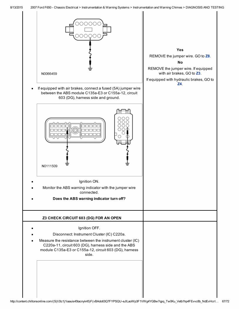
8/13/2015 2007 Ford F650 Chassis Electrical > Instrumentation & Warning Systems > Instrumentation and Warning Chimes > DIAGNOSIS AND TESTING
http://content.chiltonsonline.com/(S(li3lz1j1iaauis45tacnyk45)F(vBAdo63Q7FYPSQUeJlLaoWp3F1VWg4YGBw7qpq_Tw0Ku_Vetb1hp4FEvvc8b_NdEvHcrI… 67/72
If equipped with air brakes, connect a fused (5A) jumper wirebetween the ABS module C135aE3 or C155a12, circuit
603 (DG), harness side and ground.
Ignition ON.
Monitor the ABS warning indicator with the jumper wireconnected.
Does the ABS warning indicator turn off?
YesREMOVE the jumper wire. GO to Z8.
NoREMOVE the jumper wire. If equipped
with air brakes, GO to Z3.If equipped with hydraulic brakes, GO to
Z4.
Z3 CHECK CIRCUIT 603 (DG) FOR AN OPEN
Ignition OFF.
Disconnect: Instrument Cluster (IC) C220a.
Measure the resistance between the instrument cluster (IC)C220a11, circuit 603 (DG), harness side and the ABS
module C135aE3 or C155a12, circuit 603 (DG), harnessside.
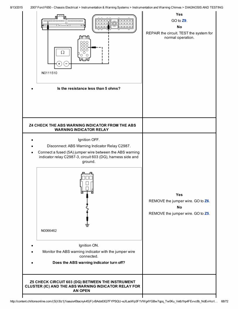
8/13/2015 2007 Ford F650 Chassis Electrical > Instrumentation & Warning Systems > Instrumentation and Warning Chimes > DIAGNOSIS AND TESTING
http://content.chiltonsonline.com/(S(li3lz1j1iaauis45tacnyk45)F(vBAdo63Q7FYPSQUeJlLaoWp3F1VWg4YGBw7qpq_Tw0Ku_Vetb1hp4FEvvc8b_NdEvHcrI… 68/72
Is the resistance less than 5 ohms?
YesGO to Z9.
NoREPAIR the circuit. TEST the system for
normal operation.
Z4 CHECK THE ABS WARNING INDICATOR FROM THE ABSWARNING INDICATOR RELAY
Ignition OFF.
Disconnect: ABS Warning Indicator Relay C2987.
Connect a fused (5A) jumper wire between the ABS warningindicator relay C29873, circuit 603 (DG), harness side and
ground.
Ignition ON.
Monitor the ABS warning indicator with the jumper wireconnected.
Does the ABS warning indicator turn off?
YesREMOVE the jumper wire. GO to Z6.
NoREMOVE the jumper wire. GO to Z5.
Z5 CHECK CIRCUIT 603 (DG) BETWEEN THE INSTRUMENTCLUSTER (IC) AND THE ABS WARNING INDICATOR RELAY FOR
AN OPEN
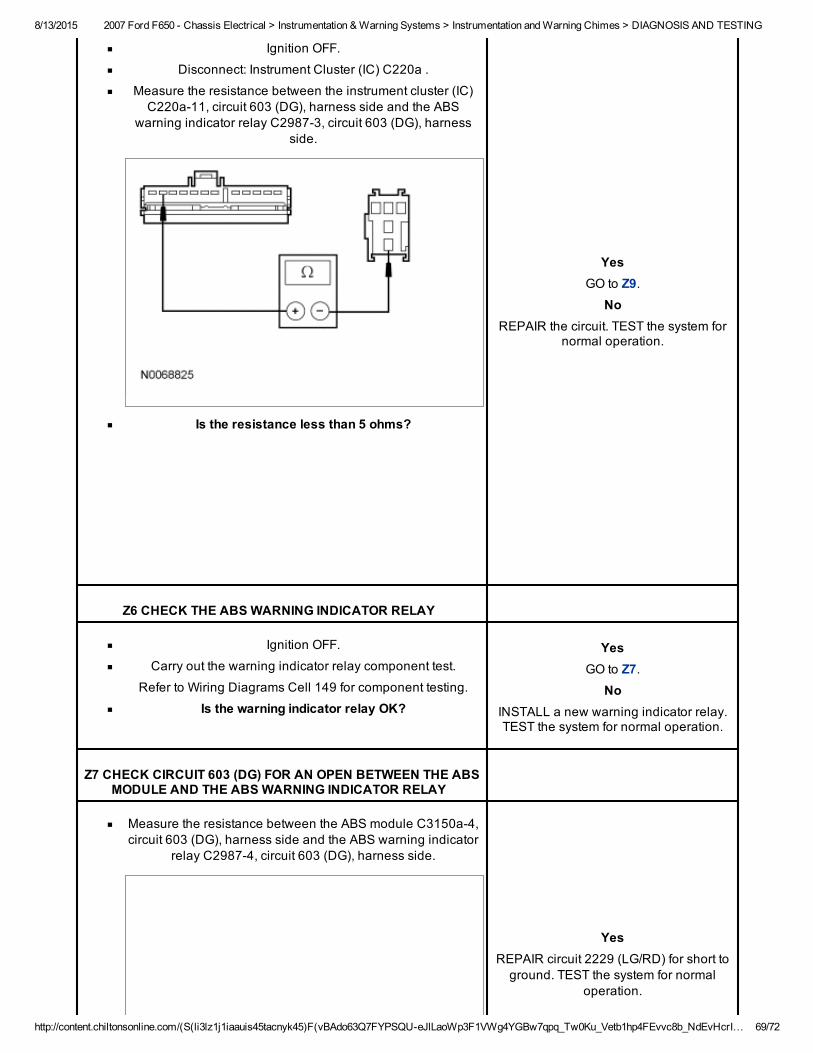
8/13/2015 2007 Ford F650 Chassis Electrical > Instrumentation & Warning Systems > Instrumentation and Warning Chimes > DIAGNOSIS AND TESTING
http://content.chiltonsonline.com/(S(li3lz1j1iaauis45tacnyk45)F(vBAdo63Q7FYPSQUeJlLaoWp3F1VWg4YGBw7qpq_Tw0Ku_Vetb1hp4FEvvc8b_NdEvHcrI… 69/72
Ignition OFF.
Disconnect: Instrument Cluster (IC) C220a .
Measure the resistance between the instrument cluster (IC)C220a11, circuit 603 (DG), harness side and the ABS
warning indicator relay C29873, circuit 603 (DG), harnessside.
Is the resistance less than 5 ohms?
YesGO to Z9.
NoREPAIR the circuit. TEST the system for
normal operation.
Z6 CHECK THE ABS WARNING INDICATOR RELAY
Ignition OFF.
Carry out the warning indicator relay component test.
Refer to Wiring Diagrams Cell 149 for component testing.
Is the warning indicator relay OK?
YesGO to Z7.
NoINSTALL a new warning indicator relay.TEST the system for normal operation.
Z7 CHECK CIRCUIT 603 (DG) FOR AN OPEN BETWEEN THE ABSMODULE AND THE ABS WARNING INDICATOR RELAY
Measure the resistance between the ABS module C3150a4,circuit 603 (DG), harness side and the ABS warning indicator
relay C29874, circuit 603 (DG), harness side.
YesREPAIR circuit 2229 (LG/RD) for short toground. TEST the system for normal
operation.
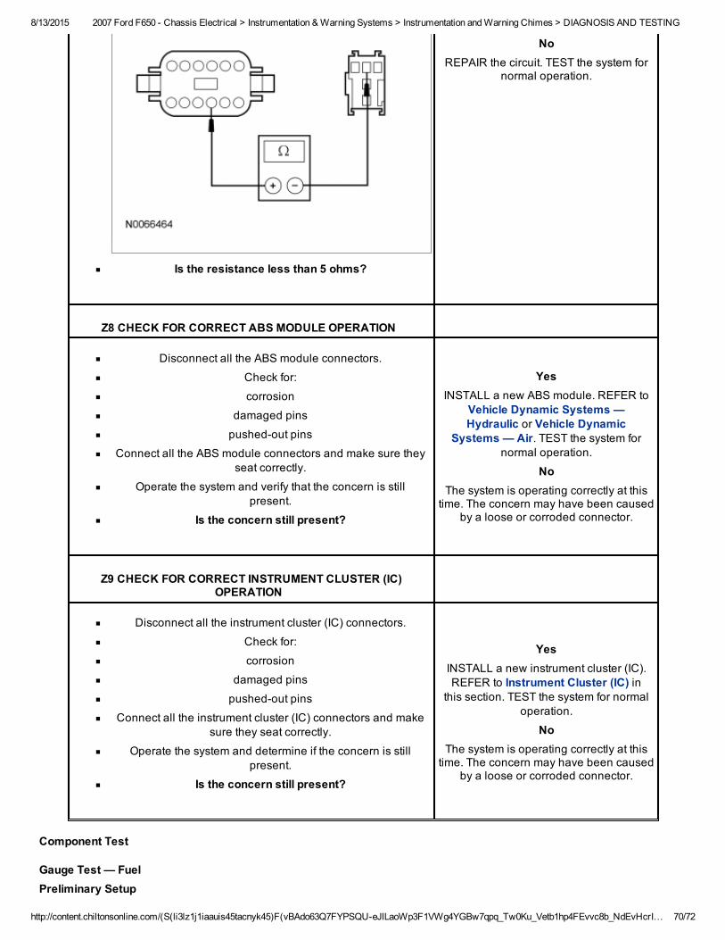
8/13/2015 2007 Ford F650 Chassis Electrical > Instrumentation & Warning Systems > Instrumentation and Warning Chimes > DIAGNOSIS AND TESTING
http://content.chiltonsonline.com/(S(li3lz1j1iaauis45tacnyk45)F(vBAdo63Q7FYPSQUeJlLaoWp3F1VWg4YGBw7qpq_Tw0Ku_Vetb1hp4FEvvc8b_NdEvHcrI… 70/72
Is the resistance less than 5 ohms?
NoREPAIR the circuit. TEST the system for
normal operation.
Z8 CHECK FOR CORRECT ABS MODULE OPERATION
Disconnect all the ABS module connectors.
Check for:
corrosion
damaged pins
pushedout pins
Connect all the ABS module connectors and make sure theyseat correctly.
Operate the system and verify that the concern is stillpresent.
Is the concern still present?
YesINSTALL a new ABS module. REFER to
Vehicle Dynamic Systems —Hydraulic or Vehicle Dynamic
Systems — Air. TEST the system fornormal operation.
NoThe system is operating correctly at thistime. The concern may have been caused
by a loose or corroded connector.
Z9 CHECK FOR CORRECT INSTRUMENT CLUSTER (IC)OPERATION
Disconnect all the instrument cluster (IC) connectors.
Check for:
corrosion
damaged pins
pushedout pins
Connect all the instrument cluster (IC) connectors and makesure they seat correctly.
Operate the system and determine if the concern is stillpresent.
Is the concern still present?
YesINSTALL a new instrument cluster (IC).REFER to Instrument Cluster (IC) in
this section. TEST the system for normaloperation.
NoThe system is operating correctly at thistime. The concern may have been caused
by a loose or corroded connector.
Component Test
Gauge Test — FuelPreliminary Setup
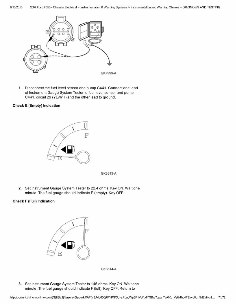
8/13/2015 2007 Ford F650 Chassis Electrical > Instrumentation & Warning Systems > Instrumentation and Warning Chimes > DIAGNOSIS AND TESTING
http://content.chiltonsonline.com/(S(li3lz1j1iaauis45tacnyk45)F(vBAdo63Q7FYPSQUeJlLaoWp3F1VWg4YGBw7qpq_Tw0Ku_Vetb1hp4FEvvc8b_NdEvHcrI… 71/72
1. Disconnect the fuel level sensor and pump C441. Connect one leadof Instrument Gauge System Tester to fuel level sensor and pumpC441, circuit 29 (YE/WH) and the other lead to ground.
Check E (Empty) Indication
2. Set Instrument Gauge System Tester to 22.4 ohms. Key ON. Wait oneminute. The fuel gauge should indicate E (empty). Key OFF.
Check F (Full) Indication
3. Set Instrument Gauge System Tester to 145 ohms. Key ON. Wait oneminute. The fuel gauge should indicate F (full). Key OFF. Return to
8/13/2015 2007 Ford F650 Chassis Electrical > Instrumentation & Warning Systems > Instrumentation and Warning Chimes > DIAGNOSIS AND TESTING
http://content.chiltonsonline.com/(S(li3lz1j1iaauis45tacnyk45)F(vBAdo63Q7FYPSQUeJlLaoWp3F1VWg4YGBw7qpq_Tw0Ku_Vetb1hp4FEvvc8b_NdEvHcrI… 72/72
the pinpoint test.