Embed Size (px)
Citation preview
DHANALAKSHMI COLLEGE OF ENGINEERING DR. VPR NAGAR, MANIMANGALAM,
CHENNAI- 601301
DEPARTMENT OF MECHANICAL ENGINEERING
ME6611- CAD/CAM LABORATORY
STUDENT NAME : _______________________________
REGISTER NUMBER : _______________________________
YEAR / SEM / SEC : _______________________________
DEPARTMENT : _______________________________
REGULATION : _______________________________
LAB MANUAL / OBSERVATION

ME6611- CAD / CAM LABORATORY 2
ME6611- CAD / CAM LABORATORY 3
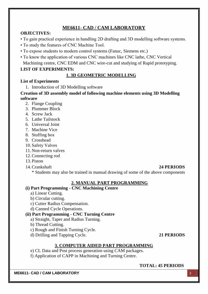
ME6611- CAD / CAM LABORATORY OBJECTIVES:
• To gain practical experience in handling 2D drafting and 3D modelling software systems.
• To study the features of CNC Machine Tool.
• To expose students to modern control systems (Fanuc, Siemens etc.)
• To know the application of various CNC machines like CNC lathe, CNC Vertical
Machining centre, CNC EDM and CNC wire-cut and studying of Rapid prototyping.
LIST OF EXPERIMENTS:
1. 3D GEOMETRIC MODELLING
List of Experiments
1. Introduction of 3D Modelling software
Creation of 3D assembly model of following machine elements using 3D Modelling
software
2. Flange Coupling
3. Plummer Block
4. Screw Jack
5. Lathe Tailstock
6. Universal Joint
7. Machine Vice
8. Stuffing box
9. Crosshead
10. Safety Valves
11. Non-return valves
12. Connecting rod
13. Piston
14. Crankshaft 24 PERIODS
* Students may also be trained in manual drawing of some of the above components
2. MANUAL PART PROGRAMMING
(i) Part Programming - CNC Machining Centre
a) Linear Cutting.
b) Circular cutting.
c) Cutter Radius Compensation.
d) Canned Cycle Operations.
(ii) Part Programming - CNC Turning Centre
a) Straight, Taper and Radius Turning.
b) Thread Cutting.
c) Rough and Finish Turning Cycle.
d) Drilling and Tapping Cycle. 21 PERIODS
3. COMPUTER AIDED PART PROGRAMMING
e) CL Data and Post process generation using CAM packages.
f) Application of CAPP in Machining and Turning Centre.
TOTAL: 45 PERIODS
ME6611- CAD / CAM LABORATORY 4
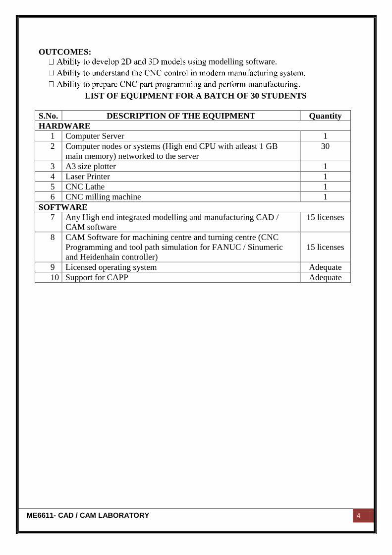
OUTCOMES:
modelling software.
LIST OF EQUIPMENT FOR A BATCH OF 30 STUDENTS
S.No. DESCRIPTION OF THE EQUIPMENT Quantity
HARDWARE
1 Computer Server 1
2 Computer nodes or systems (High end CPU with atleast 1 GB
main memory) networked to the server
30
3 A3 size plotter 1
4 Laser Printer 1
5 CNC Lathe 1
6 CNC milling machine 1
SOFTWARE
7 Any High end integrated modelling and manufacturing CAD /
CAM software
15 licenses
8 CAM Software for machining centre and turning centre (CNC
Programming and tool path simulation for FANUC / Sinumeric
and Heidenhain controller)
15 licenses
9 Licensed operating system Adequate
10 Support for CAPP Adequate
ME6611- CAD / CAM LABORATORY 5
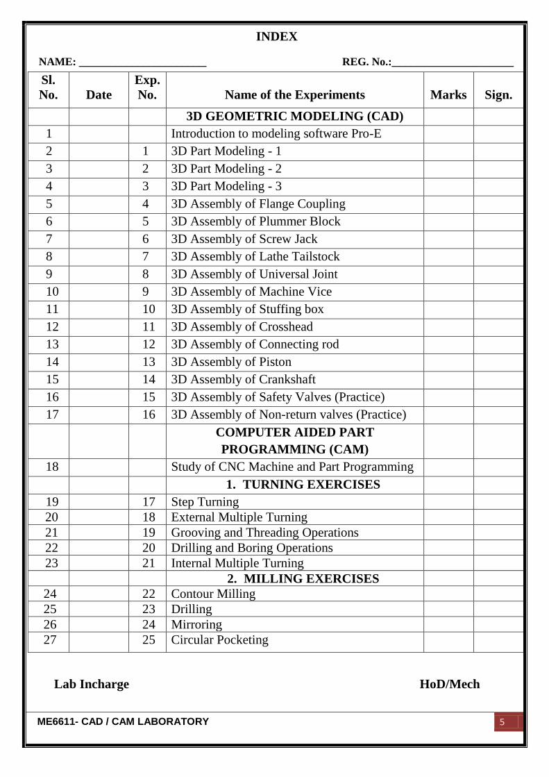
Sl.
No.
Date
Exp.
No.
Name of the Experiments
Marks
Sign.
3D GEOMETRIC MODELING (CAD)
1 Introduction to modeling software Pro-E
2 1 3D Part Modeling - 1
3 2 3D Part Modeling - 2
4 3 3D Part Modeling - 3
5 4 3D Assembly of Flange Coupling
6 5 3D Assembly of Plummer Block
7 6 3D Assembly of Screw Jack
8 7 3D Assembly of Lathe Tailstock
9 8 3D Assembly of Universal Joint
10 9 3D Assembly of Machine Vice
11 10 3D Assembly of Stuffing box
12 11 3D Assembly of Crosshead
13 12 3D Assembly of Connecting rod
14 13 3D Assembly of Piston
15 14 3D Assembly of Crankshaft
16 15 3D Assembly of Safety Valves (Practice)
17 16 3D Assembly of Non-return valves (Practice)
COMPUTER AIDED PART
PROGRAMMING (CAM)
18 Study of CNC Machine and Part Programming
1. TURNING EXERCISES
19 17 Step Turning
20 18 External Multiple Turning
21 19 Grooving and Threading Operations
22 20 Drilling and Boring Operations
23 21 Internal Multiple Turning
2. MILLING EXERCISES
24 22 Contour Milling
25 23 Drilling
26 24 Mirroring
27 25 Circular Pocketing
Lab Incharge HoD/Mech
INDEX
NAME: _______________________ REG. No.:______________________

ME6611- CAD / CAM LABORATORY 6
ME6611- CAD / CAM LABORATORY 7
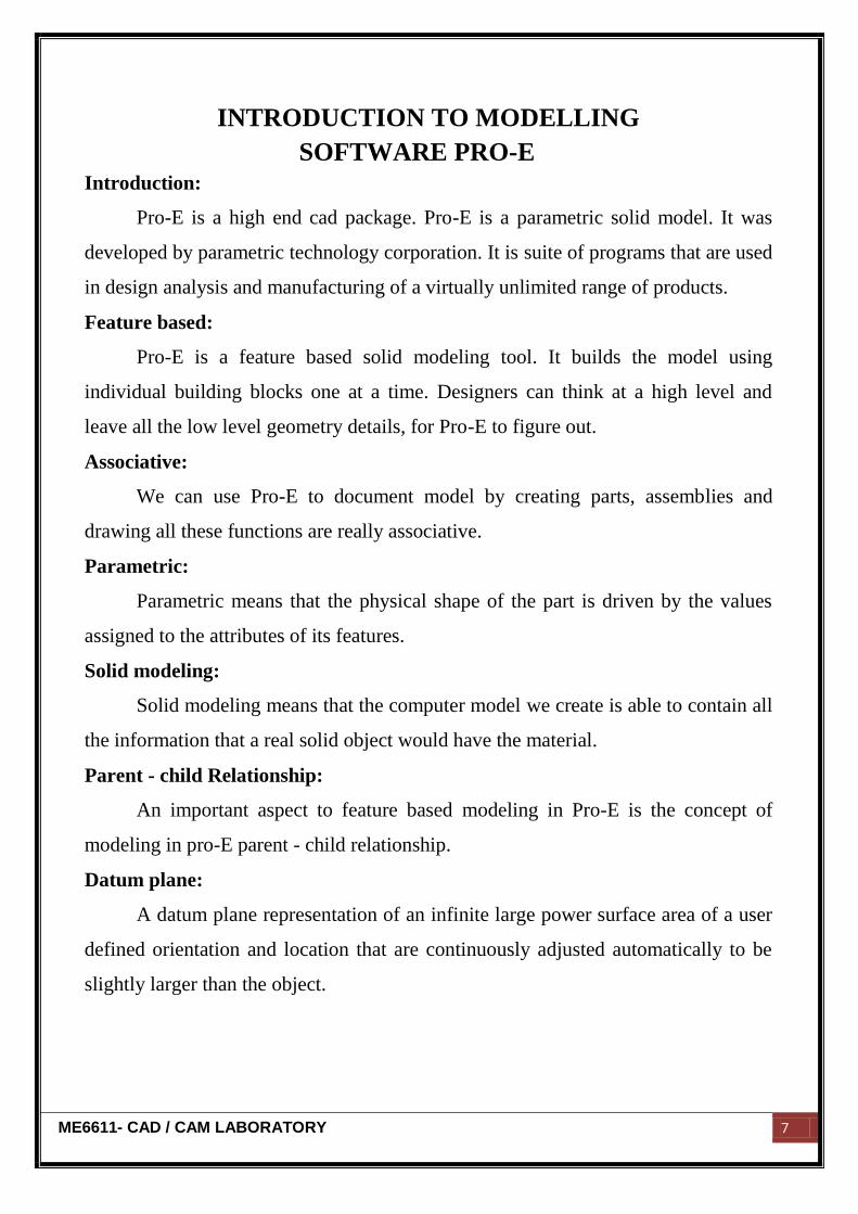
INTRODUCTION TO MODELLING
SOFTWARE PRO-E
Introduction:
Pro-E is a high end cad package. Pro-E is a parametric solid model. It was
developed by parametric technology corporation. It is suite of programs that are used
in design analysis and manufacturing of a virtually unlimited range of products.
Feature based:
Pro-E is a feature based solid modeling tool. It builds the model using
individual building blocks one at a time. Designers can think at a high level and
leave all the low level geometry details, for Pro-E to figure out.
Associative:
We can use Pro-E to document model by creating parts, assemblies and
drawing all these functions are really associative.
Parametric:
Parametric means that the physical shape of the part is driven by the values
assigned to the attributes of its features.
Solid modeling:
Solid modeling means that the computer model we create is able to contain all
the information that a real solid object would have the material.
Parent - child Relationship:
An important aspect to feature based modeling in Pro-E is the concept of
modeling in pro-E parent - child relationship.
Datum plane:
A datum plane representation of an infinite large power surface area of a user
defined orientation and location that are continuously adjusted automatically to be
slightly larger than the object.
ME6611- CAD / CAM LABORATORY 8
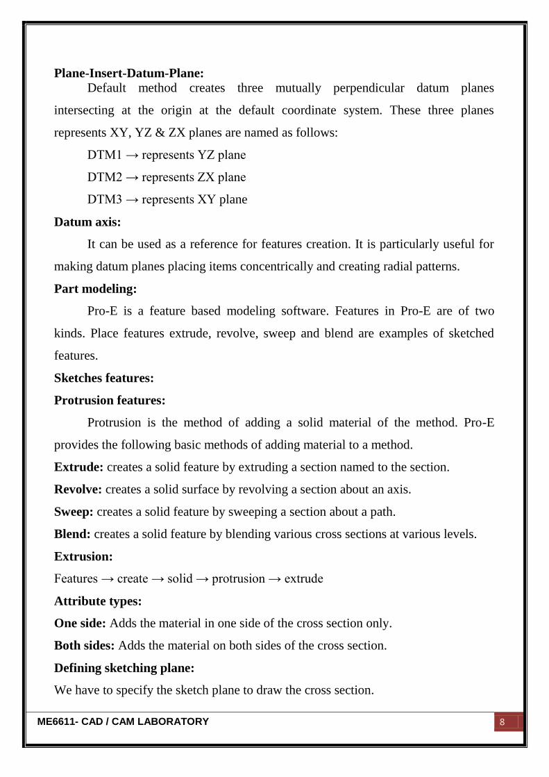
Plane-Insert-Datum-Plane:
Default method creates three mutually perpendicular datum planes
intersecting at the origin at the default coordinate system. These three planes
represents XY, YZ & ZX planes are named as follows:
DTM1 → represents YZ plane
DTM2 → represents ZX plane
DTM3 → represents XY plane
Datum axis:
It can be used as a reference for features creation. It is particularly useful for
making datum planes placing items concentrically and creating radial patterns.
Part modeling:
Pro-E is a feature based modeling software. Features in Pro-E are of two
kinds. Place features extrude, revolve, sweep and blend are examples of sketched
features.
Sketches features:
Protrusion features:
Protrusion is the method of adding a solid material of the method. Pro-E
provides the following basic methods of adding material to a method.
Extrude: creates a solid feature by extruding a section named to the section.
Revolve: creates a solid surface by revolving a section about an axis.
Sweep: creates a solid feature by sweeping a section about a path.
Blend: creates a solid feature by blending various cross sections at various levels.
Extrusion:
Features → create → solid → protrusion → extrude
Attribute types:
One side: Adds the material in one side of the cross section only.
Both sides: Adds the material on both sides of the cross section.
Defining sketching plane:
We have to specify the sketch plane to draw the cross section.
ME6611- CAD / CAM LABORATORY 9
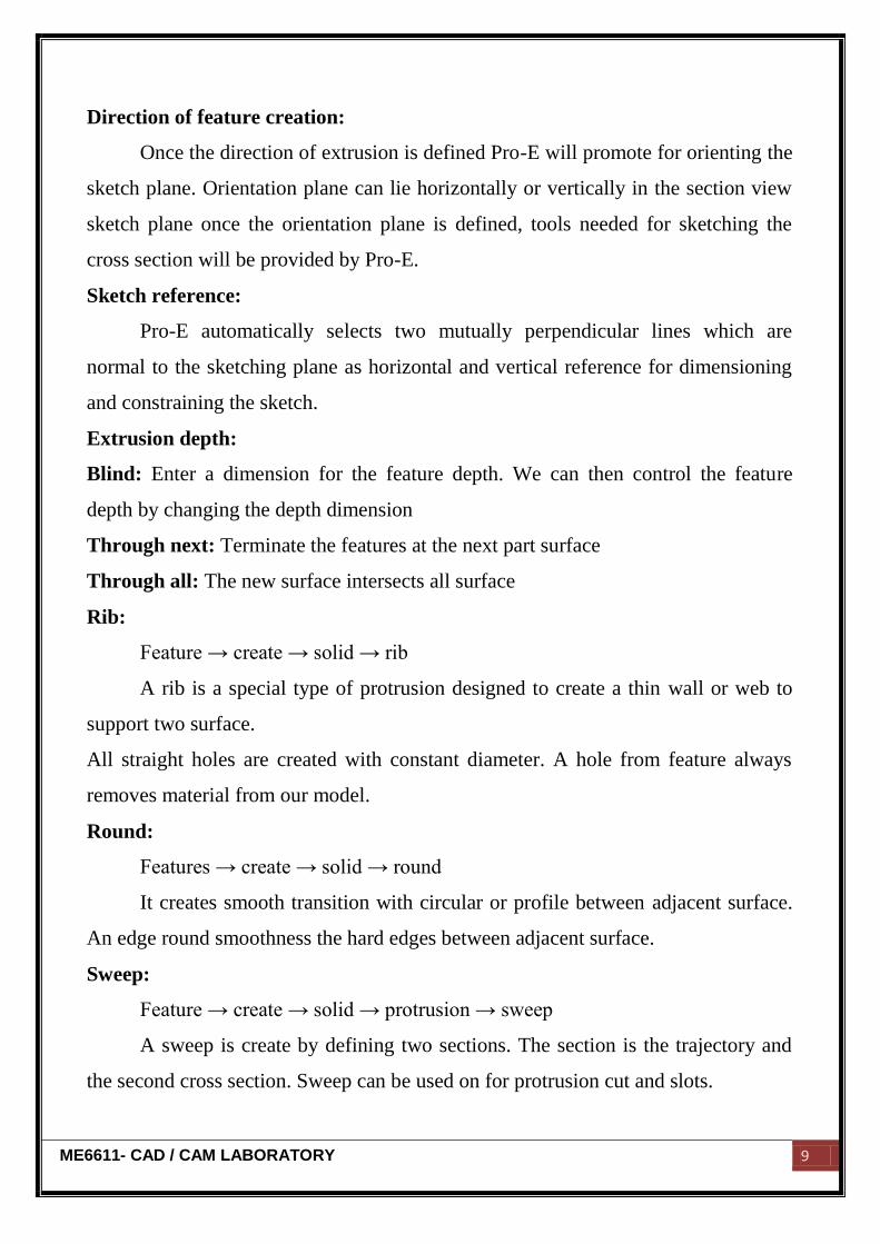
Direction of feature creation:
Once the direction of extrusion is defined Pro-E will promote for orienting the
sketch plane. Orientation plane can lie horizontally or vertically in the section view
sketch plane once the orientation plane is defined, tools needed for sketching the
cross section will be provided by Pro-E.
Sketch reference:
Pro-E automatically selects two mutually perpendicular lines which are
normal to the sketching plane as horizontal and vertical reference for dimensioning
and constraining the sketch.
Extrusion depth:
Blind: Enter a dimension for the feature depth. We can then control the feature
depth by changing the depth dimension
Through next: Terminate the features at the next part surface
Through all: The new surface intersects all surface
Rib:
Feature → create → solid → rib
A rib is a special type of protrusion designed to create a thin wall or web to
support two surface.
All straight holes are created with constant diameter. A hole from feature always
removes material from our model.
Round:
Features → create → solid → round
It creates smooth transition with circular or profile between adjacent surface.
An edge round smoothness the hard edges between adjacent surface.
Sweep:
Feature → create → solid → protrusion → sweep
A sweep is create by defining two sections. The section is the trajectory and
the second cross section. Sweep can be used on for protrusion cut and slots.
ME6611- CAD / CAM LABORATORY 10
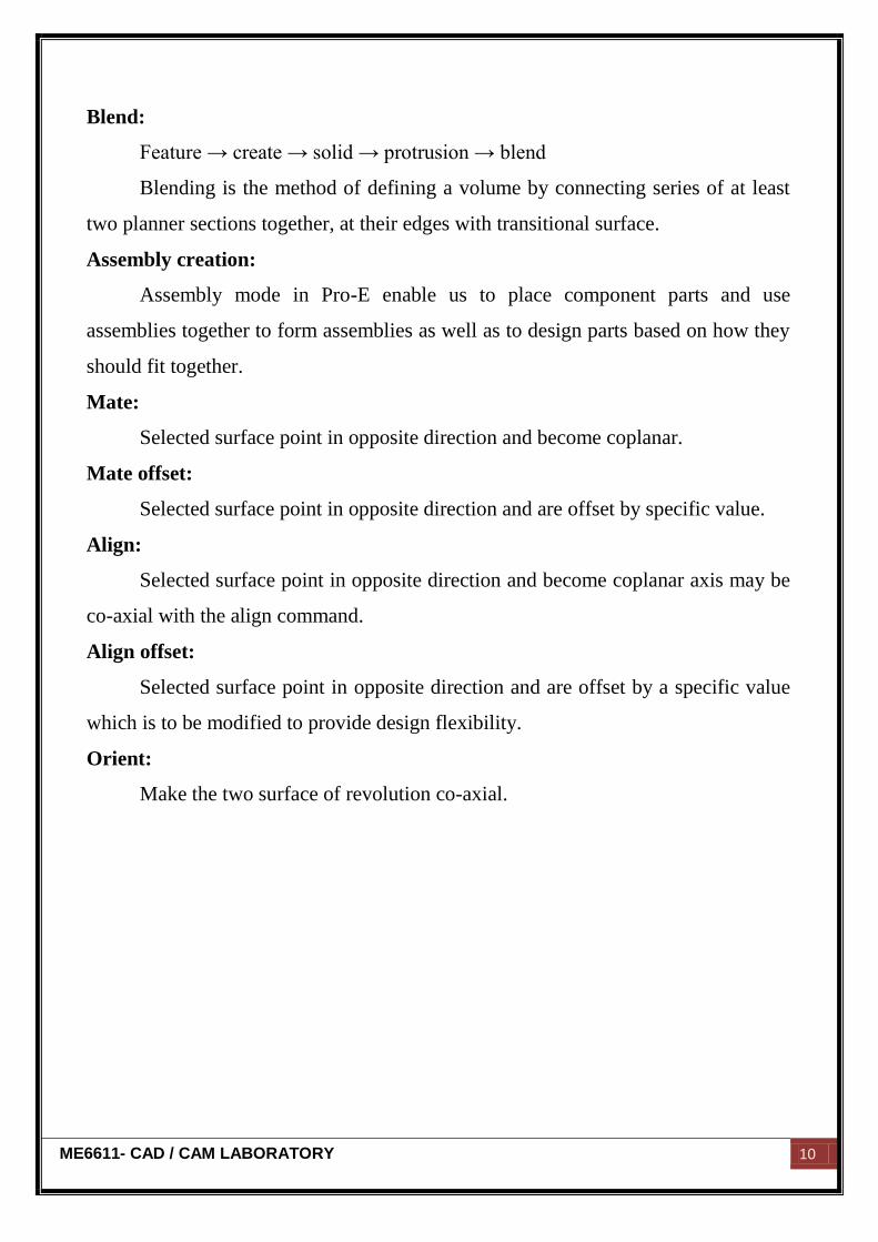
Blend:
Feature → create → solid → protrusion → blend
Blending is the method of defining a volume by connecting series of at least
two planner sections together, at their edges with transitional surface.
Assembly creation:
Assembly mode in Pro-E enable us to place component parts and use
assemblies together to form assemblies as well as to design parts based on how they
should fit together.
Mate:
Selected surface point in opposite direction and become coplanar.
Mate offset:
Selected surface point in opposite direction and are offset by specific value.
Align:
Selected surface point in opposite direction and become coplanar axis may be
co-axial with the align command.
Align offset:
Selected surface point in opposite direction and are offset by a specific value
which is to be modified to provide design flexibility.
Orient:
Make the two surface of revolution co-axial.
ME6611- CAD / CAM LABORATORY 11
3D PART MODELING
ME6611- CAD / CAM LABORATORY 12
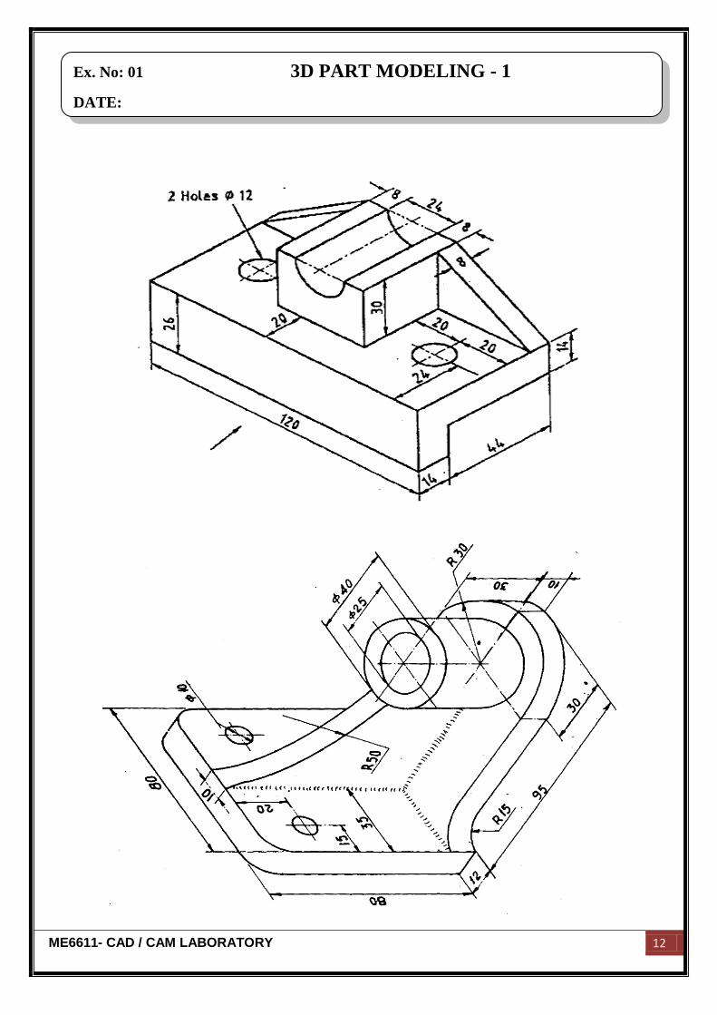
Ex. No: 01 3D PART MODELING - 1
DATE:
ME6611- CAD / CAM LABORATORY 13
Aim:
To create a 3D part model by using standard CAD software Pro-E.
Hardware required:
250 GB hard disc,8 GB ram, core 2 quad processor, NVIDA graphic card, monitor,
mouse and key board.
Software required:
Pro-E Wildfire 4.0
Commands used:
Part diagram:
Extrude → Sketch → Sketch to dimension → Ok
Hole → Sketch → Given dimension → Ok
Revolve → Sketch plane → Sketches → Centerlines → Sketch to dimension → Ok
Result:
Thus the given 3D part model was created by using standard CAD software Pro-E.
Ex. No: 01 3D PART MODELING - 1
DATE:
ME6611- CAD / CAM LABORATORY 14
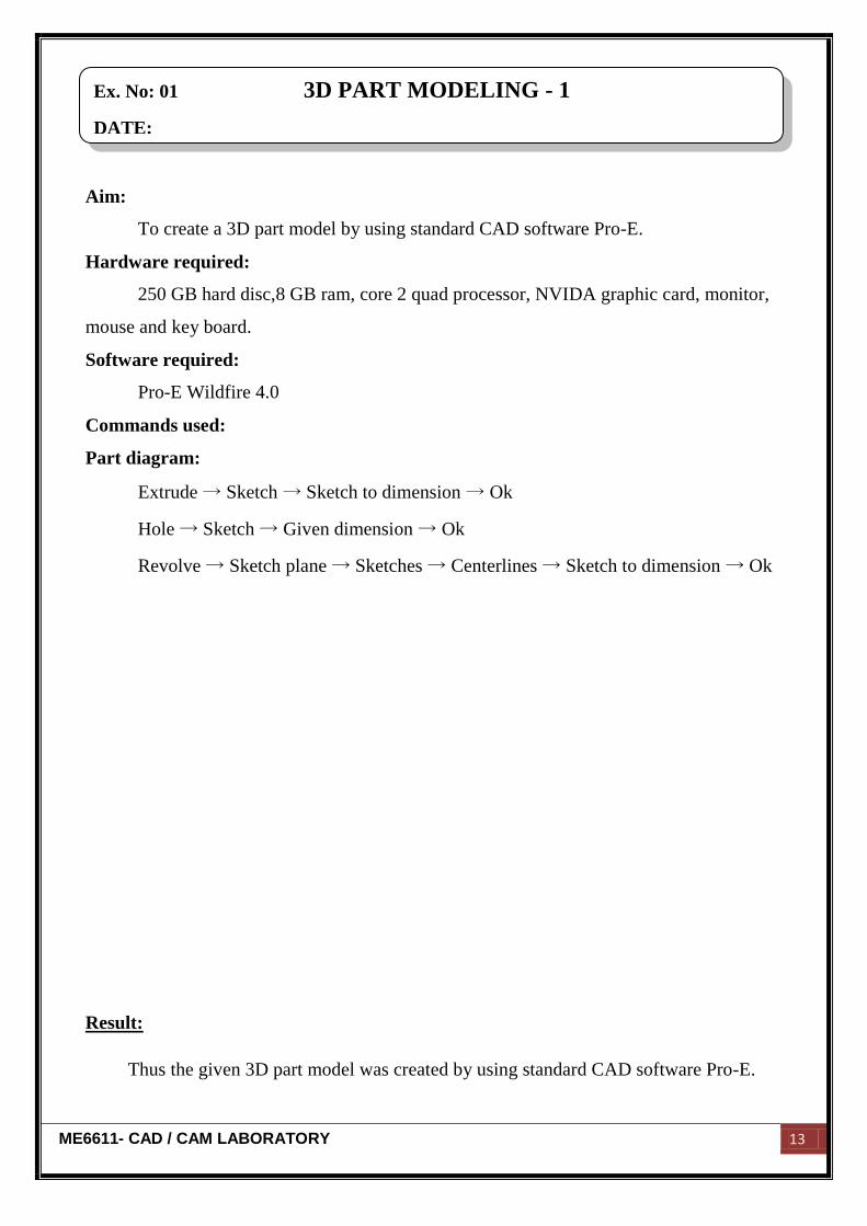
Ex. No: 02 3D PART MODELING - 2
DATE:

ME6611- CAD / CAM LABORATORY 15
Aim:
To create a 3D part model by using standard CAD software Pro-E.
Hardware required:
250 GB hard disc,8 GB ram, core 2 quad processor, NVIDA graphic card, monitor,
mouse and key board.
Software required:
Pro-E Wildfire 4.0
Commands used:
Part diagram:
Extrude → Sketch → Sketch to dimension → Ok
Hole → Sketch → Given dimension → Ok
Revolve → Sketch plane → Sketches → Centerlines → Sketch to dimension → Ok
Result:
Thus the given 3D part model was created by using standard CAD software Pro-E.
Ex. No: 02 3D PART MODELING - 2
DATE:
ME6611- CAD / CAM LABORATORY 16
0. Adjust the coolant nozzle on the cutting edges and start the coolant pump.
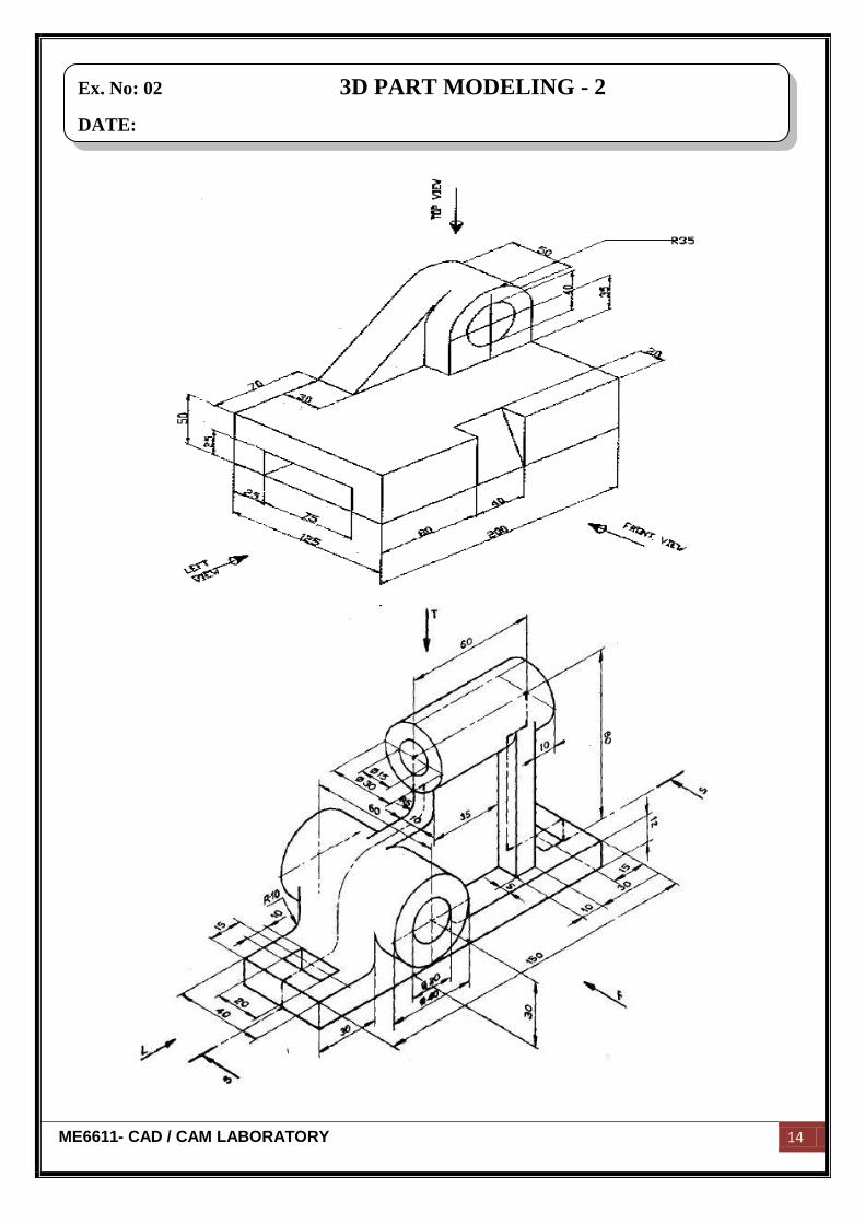
Ex. No: 03 3D PART MODELING - 3
DATE:
ME6611- CAD / CAM LABORATORY 17
Aim:
To create a 3D part model by using standard CAD software Pro-E.
Hardware required:
250 GB hard disc,8 GB ram, core 2 quad processor, NVIDA graphic card, monitor,
mouse and key board.
Software required:
Pro-E Wildfire 4.0
Commands used:
Part diagram:
Extrude → Sketch → Sketch to dimension → Ok
Hole → Sketch → Given dimension → Ok
Revolve → Sketch plane → Sketches → Centerlines → Sketch to dimension → Ok
Result:
Thus the given 3D part model was created by using standard CAD software Pro-E.
Ex. No: 03 3D PART MODELING - 3
DATE:

ME6611- CAD / CAM LABORATORY 18

ME6611- CAD / CAM LABORATORY 19
ASSEMBLY DRAWINGS
ME6611- CAD / CAM LABORATORY 20
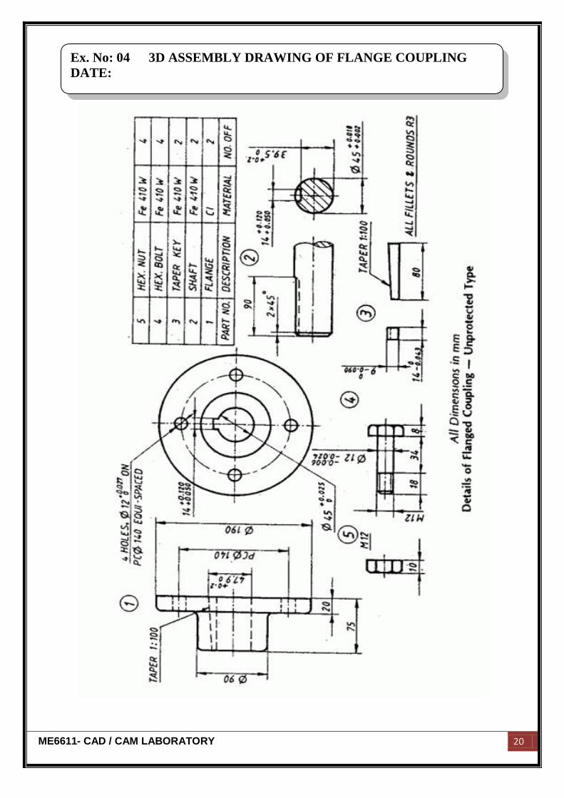
Ex. No: 04 3D ASSEMBLY DRAWING OF FLANGE COUPLING
DATE:
ME6611- CAD / CAM LABORATORY 21
Aim:
To create various parts of flange coupling and assemble them by using standard
CAD software Pro-E.
Hardware required:
250 GB hard disc,8 GB ram, core 2 quad processor, NVIDA graphic card, monitor,
mouse and key board.
Software required:
Pro-E Wildfire 4.0
Description of the component:
A coupling is a device used to connect two shafts together at their ends for the
purpose of transmitting power permitting some degree of misalignment or end movement
or both.
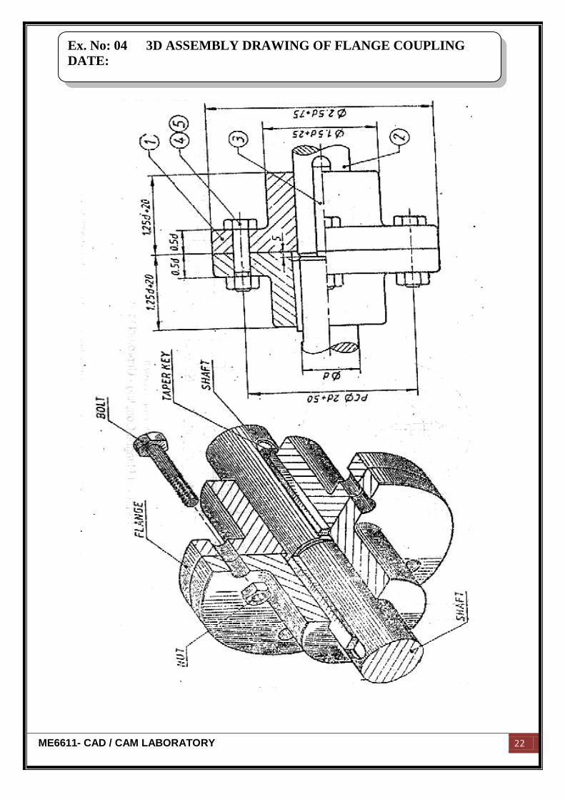
Assembly:
The shaft end is fitted to both male and female flange. Now both the male and
female flange are joined together with help of the nut and bolt.
Commands used:
Part diagram:
Extrude → Sketch → Sketch to dimension → Ok
Hole → Sketch → Given dimension → Ok
Revolve → Sketch plane → Sketches → Centerlines → Sketch to dimension → Ok
Assembly:
Assembly → Set default → Assembly according to alignment → Fully constrained
→ Ok
Ex. No: 04 3D ASSEMBLY DRAWING OF FLANGE COUPLING
DATE:
ME6611- CAD / CAM LABORATORY 22
Ex. No: 04 3D ASSEMBLY DRAWING OF FLANGE COUPLING
DATE:

ME6611- CAD / CAM LABORATORY 23
Result:
Thus the given various part of flange coupling had been created and assembled by
using standard CAD software Pro-E.
Ex. No: 04 3D ASSEMBLY DRAWING OF FLANGE COUPLING
DATE:
ME6611- CAD / CAM LABORATORY 24
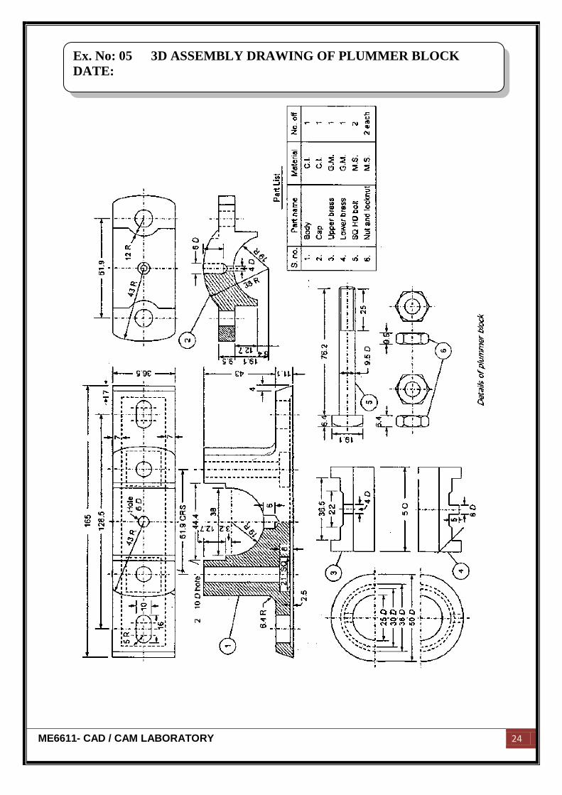
Ex. No: 05 3D ASSEMBLY DRAWING OF PLUMMER BLOCK
DATE:
ME6611- CAD / CAM LABORATORY 25
Aim:
To create various parts of Plummer block and assemble them by using standard
CAD software Pro-E.
Hardware required:
250 GB hard disc,8 GB ram, core 2 quad processor, NVIDA graphic card, monitor,
mouse and key board.
Software required:
Pro-E Wildfire 4.0
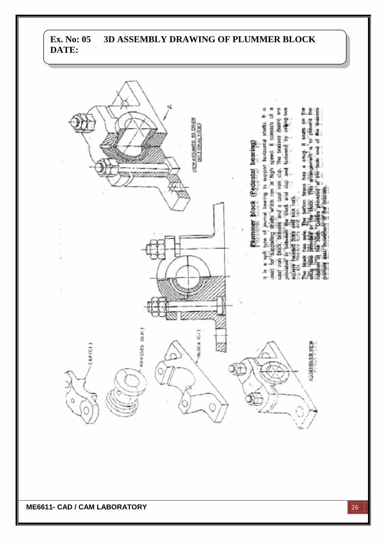
Description of the component:
A Plummer block is known as pillow block or bearing housing, is a pedestal used to
provide support for a rotating shaft with the help of compatible bearings.
Assembly:
The brass part is mounted over the block. The block is covered along with brass part
with help of a cover nut and lock nut.
Commands used:
Part diagram:
Extrude → Sketch → Sketch to dimension → Ok
Hole → Sketch → Given dimension → Ok
Revolve → Sketch plane → Sketches → Centerlines → Sketch to dimension → Ok
Assembly:
Assembly → Set default → Assembly according to alignment → Fully constrained
→ Ok
Ex. No: 05 3D ASSEMBLY DRAWING OF PLUMMER BLOCK
DATE:
ME6611- CAD / CAM LABORATORY 26
Ex. No: 05 3D ASSEMBLY DRAWING OF PLUMMER BLOCK
DATE:

ME6611- CAD / CAM LABORATORY 27
Result:
Thus the given various part of Plummer block had been created and assembled by
using standard CAD software Pro-E.
Ex. No: 05 3D ASSEMBLY DRAWING OF PLUMMER BLOCK
DATE:
ME6611- CAD / CAM LABORATORY 28
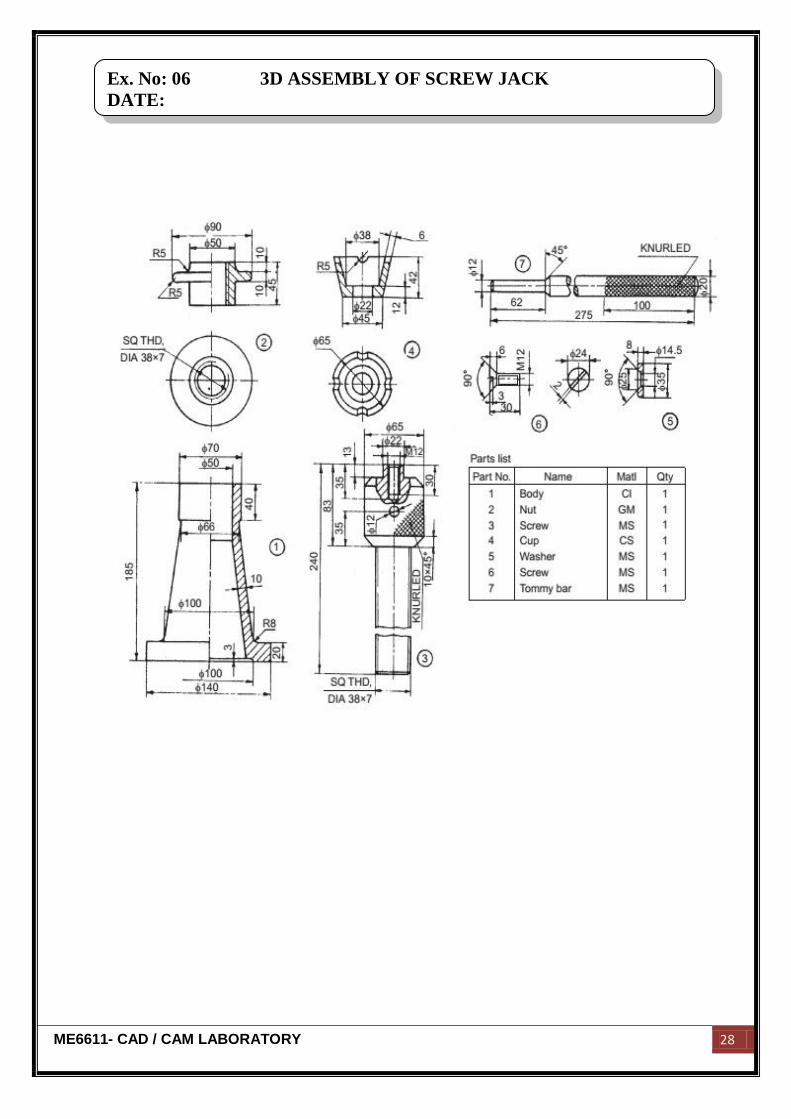
Ex. No: 06 3D ASSEMBLY OF SCREW JACK
DATE:
ME6611- CAD / CAM LABORATORY 29
Aim:
To create various parts of screw jack and assemble them by using standard CAD
software Pro-E.
Hardware required:
250 GB hard disc,8 GB ram, core 2 quad processor, NVIDA graphic card, monitor,
mouse and key board.
Software required:
Pro-E Wildfire 4.0
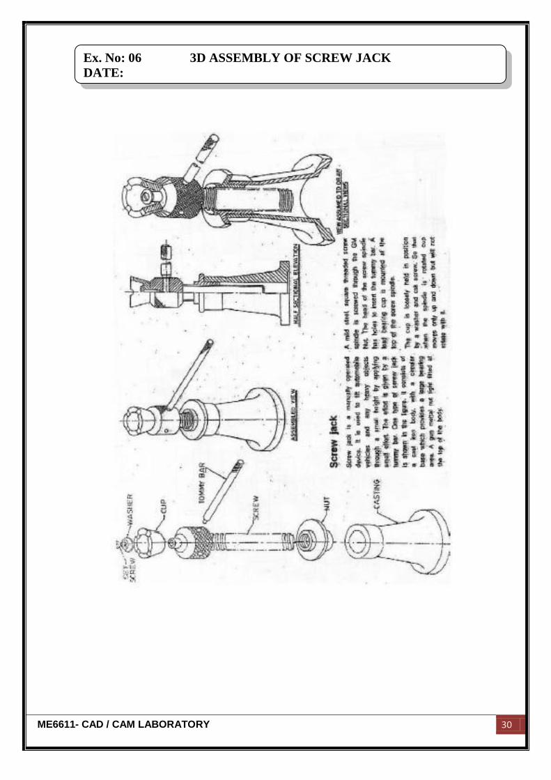
Description of the component:
A screw jack is used to raise heavy loads through a small vertical distance. In
automobile industries, it is used to raise the vehicles for repair works. The nut is a separate
piece press fitted into the hole of the body.
Assembly:
The cut is fitted on the top of the screw spindle. The nut arrangement is kept in
between the screw spindle and the body.
Commands used:
Part diagram:
Extrude → Sketch → Sketch to dimension → Ok
Hole → Sketch → Given dimension → Ok
Revolve → Sketch plane → Sketches → Centerlines → Sketch to dimension → Ok
Assembly:
Assembly → Set default → Assembly according to alignment → Fully constrained
→ Ok
Ex. No: 06 3D ASSEMBLY OF SCREW JACK
DATE:
ME6611- CAD / CAM LABORATORY 30
Ex. No: 06 3D ASSEMBLY OF SCREW JACK
DATE:

ME6611- CAD / CAM LABORATORY 31
Result:
Thus the given various part of screw jack had been created and assembled by using
standard CAD software Pro-E.
Ex. No: 06 3D ASSEMBLY OF SCREW JACK
DATE:
ME6611- CAD / CAM LABORATORY 32
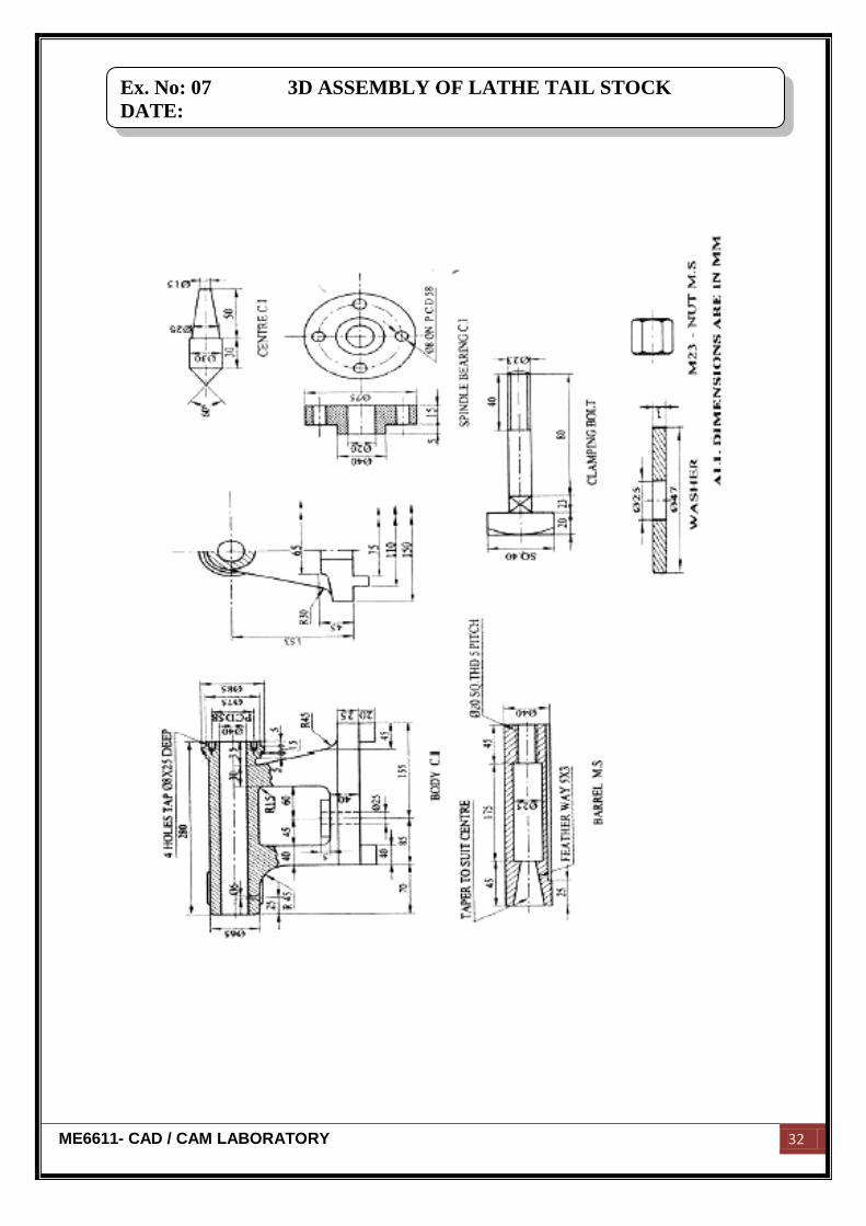
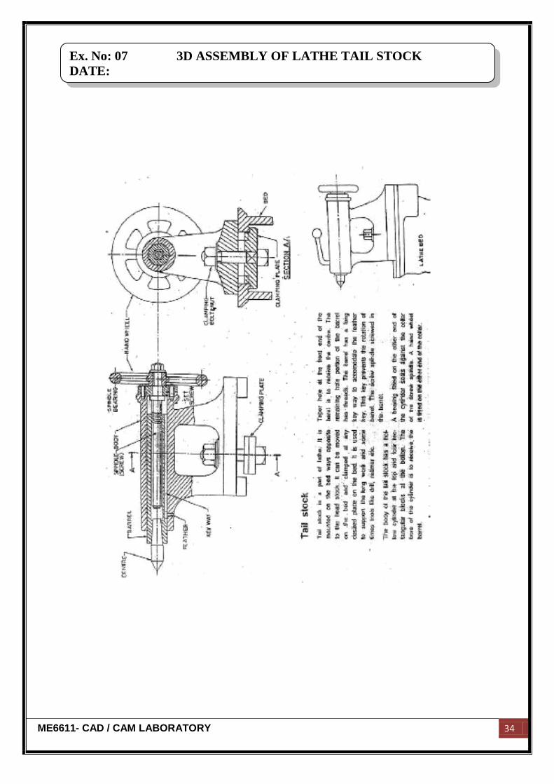
Ex. No: 07 3D ASSEMBLY OF LATHE TAIL STOCK
DATE:
ME6611- CAD / CAM LABORATORY 33
Aim:
To create various parts of lathe tail stock and assemble them by using standard CAD
software Pro-E.
Hardware required:
250 GB hard disc,8 GB ram, core 2 quad processor, NVIDA graphic card, monitor,
mouse and key board.
Software required:
Pro-E Wildfire 4.0
Description of the component:
Tail stock is a part of lathe. It is mounted on the bed ways opposite to the head
stock. It can be moved on the bed and clamped at any desired place on the bed. It is used to
support the long work and sometimes tools like drill, reamer, etc.
Assembly:
This body of the tail stock has a hollow cylinder at the top and four rectangular
blocks the bottom. The bore of the cylinder is to receive the barrel. Taper hole at the front
end of the barrel is to receive the centre. The remaining hole portion of the barrel has
threads. The barrel has a long key way to accommodate the feather key.
Commands used:
Part diagram:
Extrude → Sketch → Sketch to dimension → Ok
Hole → Sketch → Given dimension → Ok
Revolve → Sketch plane → Sketches → Centerlines → Sketch to dimension → Ok
Assembly:
Assembly → Set default → Assembly according to alignment → Fully constrained
→ Ok
Ex. No: 07 3D ASSEMBLY OF LATHE TAIL STOCK
DATE:
ME6611- CAD / CAM LABORATORY 34
Ex. No: 07 3D ASSEMBLY OF LATHE TAIL STOCK
DATE:

ME6611- CAD / CAM LABORATORY 35
Result:
Thus the given various part of lathe tail stock had been created and assembled by
using standard CAD software Pro-E.
Ex. No: 07 3D ASSEMBLY OF LATHE TAIL STOCK
DATE:
ME6611- CAD / CAM LABORATORY 36
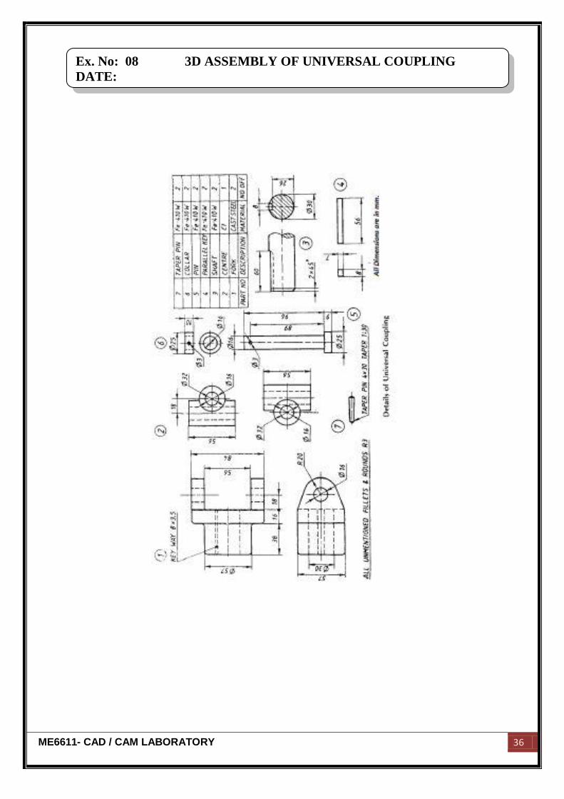
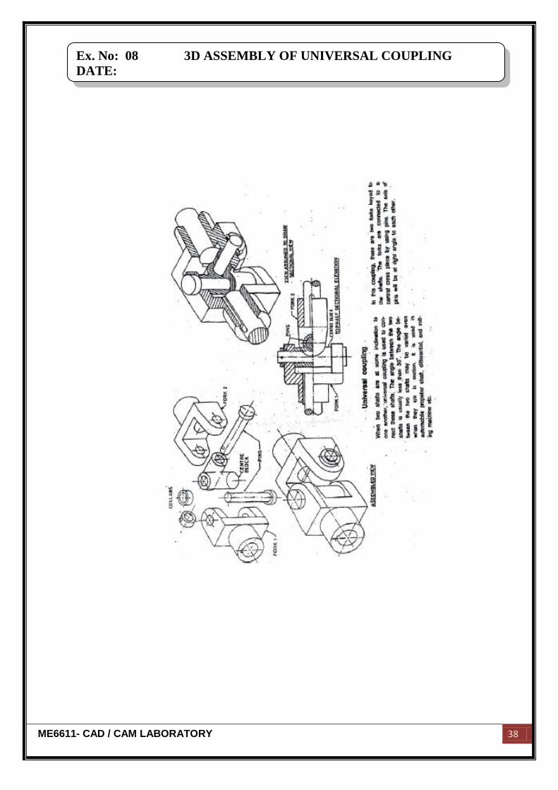
Ex. No: 08 3D ASSEMBLY OF UNIVERSAL COUPLING
DATE:
ME6611- CAD / CAM LABORATORY 37
Aim:
To create various parts of universal coupling and assemble them by using standard
CAD software Pro-E.
Hardware required:
250 GB hard disc,8 GB ram, core 2 quad processor, NVIDA graphic card, monitor,
mouse and key board.
Software required:
Pro-E Wildfire 4.0
Description of the component:
Universal coupling is used to connect two shafts having intersecting axes. The angle
between the two shafts is less than 30˚. It consists of two forks, centre blocks, pins.
Assembly:
The centre block is inserted into one of the forks. A collar is assembled on the other
ends of the pin and locked by means of a cotter, the centre block such that the two fork
ends are at right angles to each other.
Commands used:
Part diagram:
Extrude → Sketch → Sketch to dimension → Ok
Hole → Sketch → Given dimension → Ok
Revolve → Sketch plane → Sketches → Centerline → Sketch to dimension → Ok
Assembly:
Assembly → Set default → Assembly according to alignment → Fully constrained
→ Ok
Ex. No: 08 3D ASSEMBLY OF UNIVERSAL COUPLING
DATE:
ME6611- CAD / CAM LABORATORY 38
Ex. No: 08 3D ASSEMBLY OF UNIVERSAL COUPLING
DATE:

ME6611- CAD / CAM LABORATORY 39
Result:
Thus the given various part of universal coupling had been created and assembled
by using standard CAD software Pro-E.
Ex. No: 08 3D ASSEMBLY OF UNIVERSAL COUPLING
DATE:
ME6611- CAD / CAM LABORATORY 40
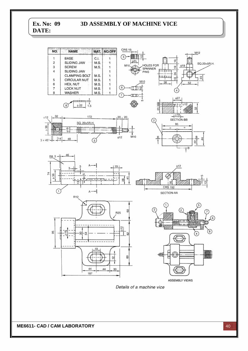
Ex. No: 09 3D ASSEMBLY OF MACHINE VICE
DATE:
ME6611- CAD / CAM LABORATORY 41
Aim:
To create various parts of machine vice and assemble them by using standard CAD
software Pro-E.
Hardware required:
250 GB hard disc,8 GB ram, core 2 quad processor, NVIDA graphic card, monitor,
mouse and key board.
Software required:
Pro-E Wildfire 4.0
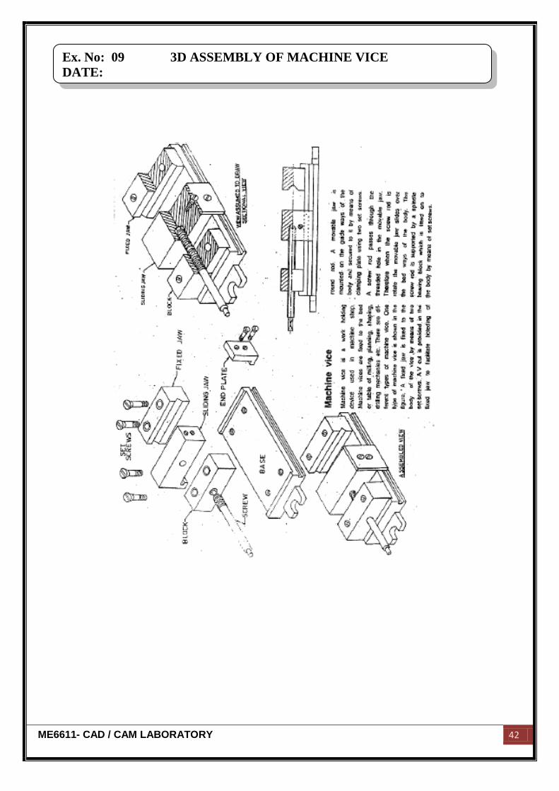
Description of the component:
Machine vice is a work holding device. It is used to machine shape. The machine
vice consists of a brass, a block, fixed jaw, screw, spindle and plate, set screws, etc.
Assembly:
The block is screwed to the base at one end. At another end the fixed end jaw is
screwed. The spindle is then screwed through the block and sliding.
Commands used:
Part diagram:
Extrude → Sketch → Sketch to dimension → Ok
Hole → Sketch → Given dimension → Ok
Revolve → Sketch plane → Sketches → Centerline → Sketch to dimension → Ok
Assembly:
Assembly → Set default → Assembly according to alignment → Fully constrained
→ Ok
Ex. No: 09 3D ASSEMBLY OF MACHINE VICE
DATE:
ME6611- CAD / CAM LABORATORY 42
Ex. No: 09 3D ASSEMBLY OF MACHINE VICE
DATE:

ME6611- CAD / CAM LABORATORY 43
Result:
Thus the given various part of machine vice had been created and assembled by
using standard CAD software Pro-E.
Ex. No: 09 3D ASSEMBLY OF MACHINE VICE
DATE:
ME6611- CAD / CAM LABORATORY 44
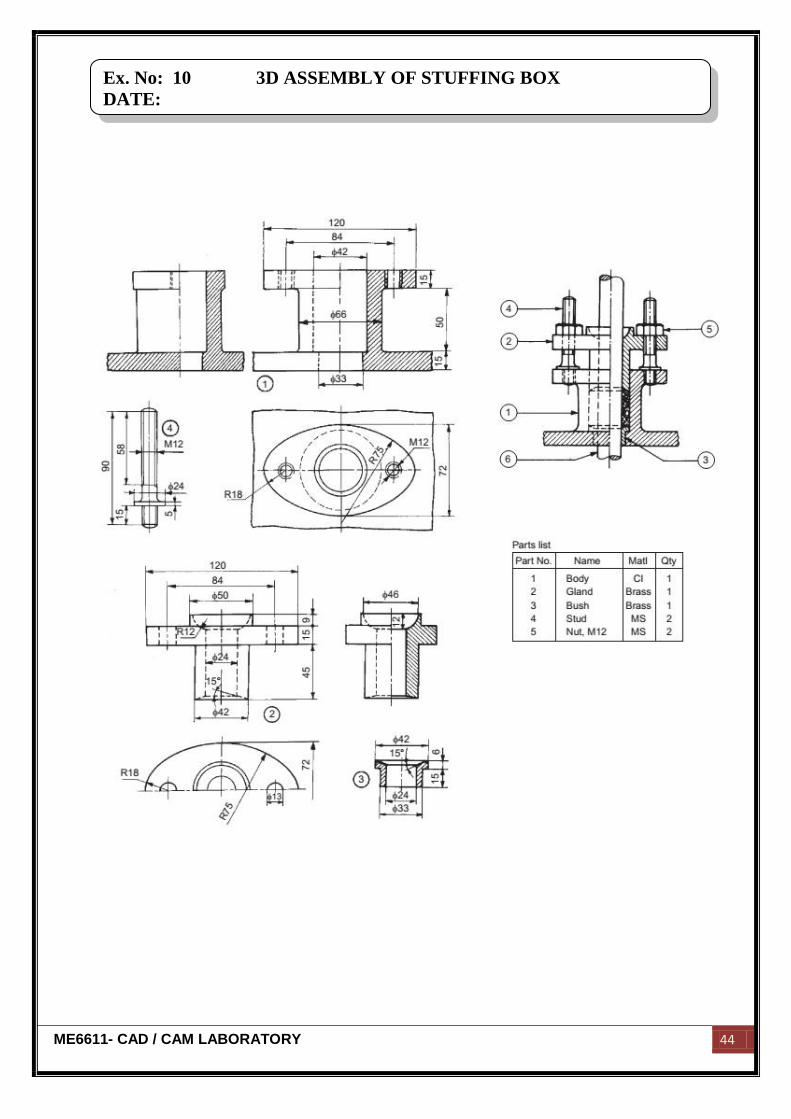
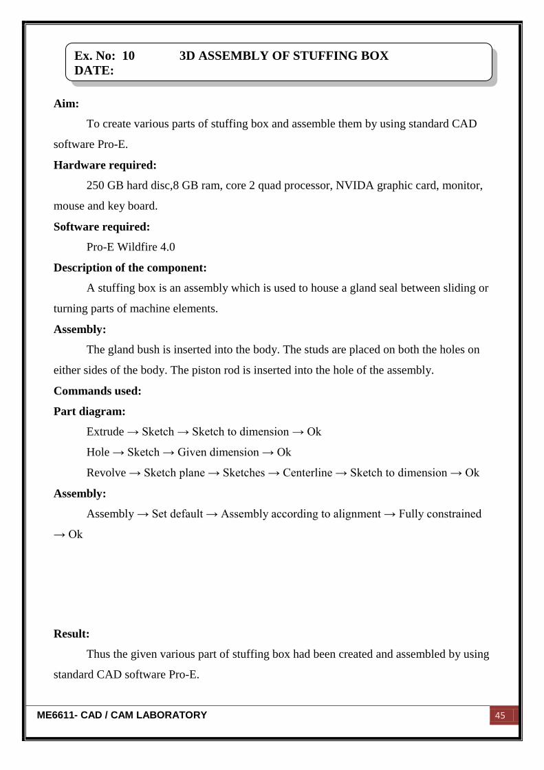
Ex. No: 10 3D ASSEMBLY OF STUFFING BOX
DATE:
ME6611- CAD / CAM LABORATORY 45
Aim:
To create various parts of stuffing box and assemble them by using standard CAD
software Pro-E.
Hardware required:
250 GB hard disc,8 GB ram, core 2 quad processor, NVIDA graphic card, monitor,
mouse and key board.
Software required:
Pro-E Wildfire 4.0
Description of the component:
A stuffing box is an assembly which is used to house a gland seal between sliding or
turning parts of machine elements.
Assembly:
The gland bush is inserted into the body. The studs are placed on both the holes on
either sides of the body. The piston rod is inserted into the hole of the assembly.
Commands used:
Part diagram:
Extrude → Sketch → Sketch to dimension → Ok
Hole → Sketch → Given dimension → Ok
Revolve → Sketch plane → Sketches → Centerline → Sketch to dimension → Ok
Assembly:
Assembly → Set default → Assembly according to alignment → Fully constrained
→ Ok
Result:
Thus the given various part of stuffing box had been created and assembled by using
standard CAD software Pro-E.
Ex. No: 10 3D ASSEMBLY OF STUFFING BOX
DATE:
ME6611- CAD / CAM LABORATORY 46
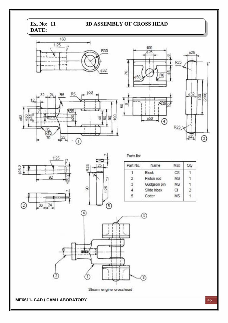
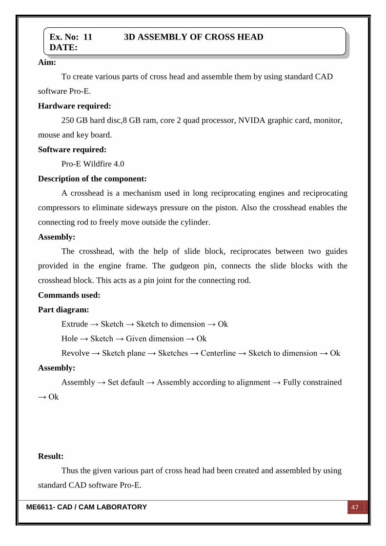
Ex. No: 11 3D ASSEMBLY OF CROSS HEAD
DATE:
ME6611- CAD / CAM LABORATORY 47
Aim:
To create various parts of cross head and assemble them by using standard CAD
software Pro-E.
Hardware required:
250 GB hard disc,8 GB ram, core 2 quad processor, NVIDA graphic card, monitor,
mouse and key board.
Software required:
Pro-E Wildfire 4.0
Description of the component:
A crosshead is a mechanism used in long reciprocating engines and reciprocating
compressors to eliminate sideways pressure on the piston. Also the crosshead enables the
connecting rod to freely move outside the cylinder.
Assembly:
The crosshead, with the help of slide block, reciprocates between two guides
provided in the engine frame. The gudgeon pin, connects the slide blocks with the
crosshead block. This acts as a pin joint for the connecting rod.
Commands used:
Part diagram:
Extrude → Sketch → Sketch to dimension → Ok
Hole → Sketch → Given dimension → Ok
Revolve → Sketch plane → Sketches → Centerline → Sketch to dimension → Ok
Assembly:
Assembly → Set default → Assembly according to alignment → Fully constrained
→ Ok
Result:
Thus the given various part of cross head had been created and assembled by using
standard CAD software Pro-E.
Ex. No: 11 3D ASSEMBLY OF CROSS HEAD
DATE:
ME6611- CAD / CAM LABORATORY 48
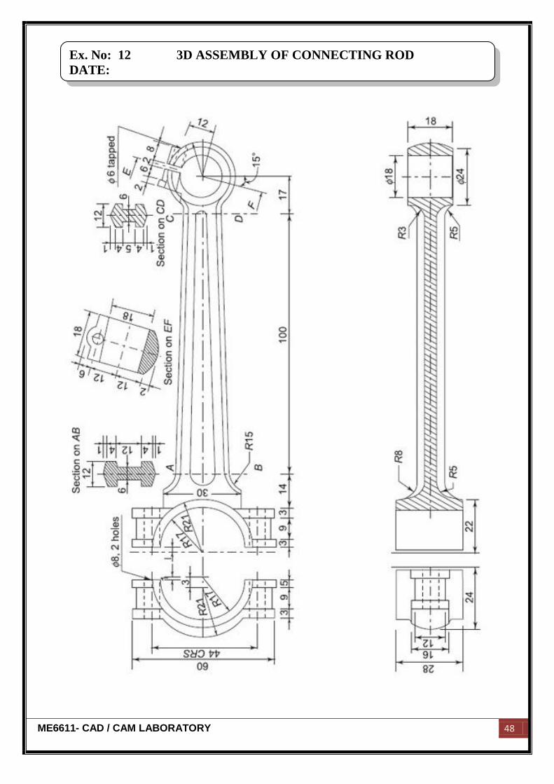
Ex. No: 12 3D ASSEMBLY OF CONNECTING ROD
DATE:
ME6611- CAD / CAM LABORATORY 49
Aim:
To create various parts of connecting rod and assemble them by using standard
CAD software Pro-E.
Hardware required:
250 GB hard disc,8 GB ram, core 2 quad processor, NVIDA graphic card, monitor,
mouse and key board.
Software required:
Pro-E Wildfire 4.0
Description of the component:
A connecting rod is an engine component that transfers motion from the piston to
the crankshaft and functions as a lever arm.
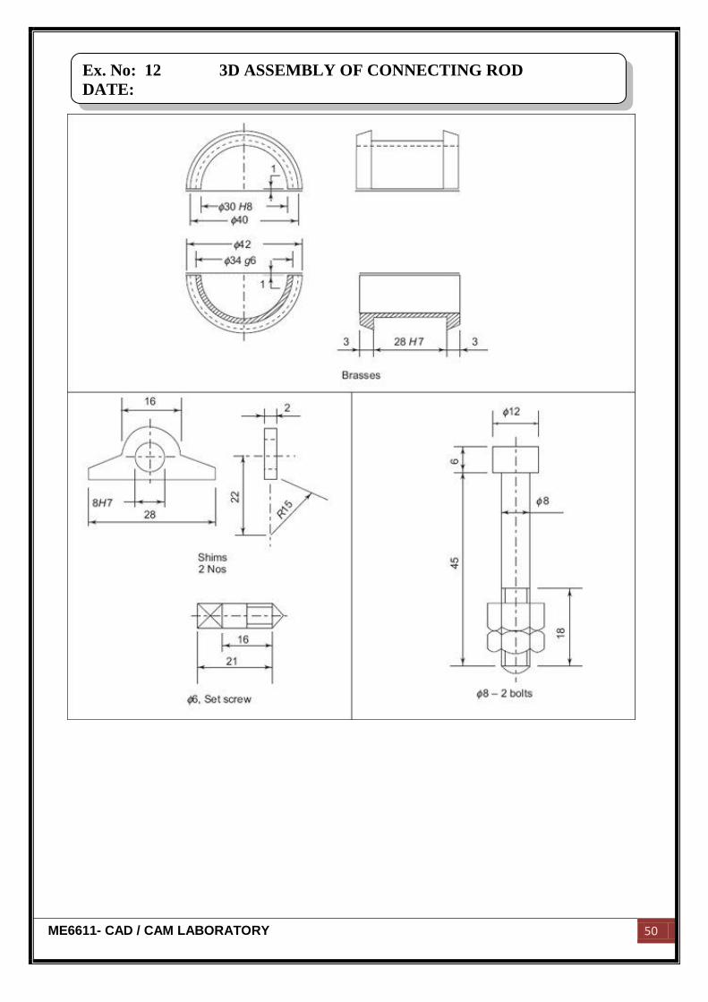
Assembly:
The bearing bush which is in one piece, is fitted at the small end of the connecting
rod. The small end of the rod is connected to the piston. The main bearing bush, which is
split into two halves, is placed at the big end of the connecting rod. The big end of the rod
is connected to the crank pin of the center crank. First, the split bearing brasses are placed
on the crank pin, then the big end of the connecting rod and the cap are clamped onto these,
by means of two bolts and nuts.
Commands used:
Part diagram:
Extrude → Sketch → Sketch to dimension → Ok
Hole → Sketch → Given dimension → Ok
Revolve → Sketch plane → Sketches → Centerline → Sketch to dimension → Ok
Assembly:
Assembly → Set default → Assembly according to alignment → Fully constrained
→ Ok
Ex. No: 12 3D ASSEMBLY OF CONNECTING ROD
DATE:
ME6611- CAD / CAM LABORATORY 50
Ex. No: 12 3D ASSEMBLY OF CONNECTING ROD
DATE:

ME6611- CAD / CAM LABORATORY 51
Result:
Thus the given various part of connecting rod had been created and assembled by
using standard CAD software Pro-E.
Ex. No: 12 3D ASSEMBLY OF CONNECTING ROD
DATE:
ME6611- CAD / CAM LABORATORY 52
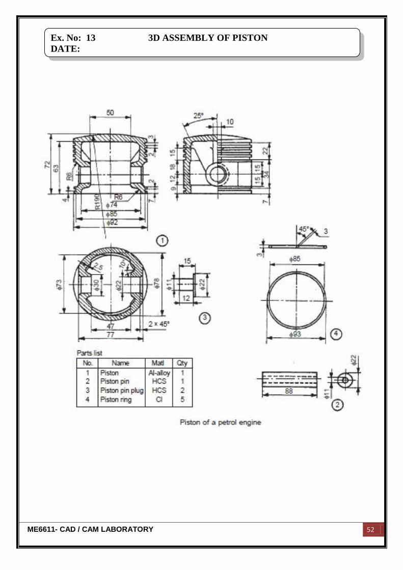
Ex. No: 13 3D ASSEMBLY OF PISTON
DATE:
ME6611- CAD / CAM LABORATORY 53
Aim:
To create various parts of piston and assemble them by using standard CAD
software Pro-E.
Hardware required:
250 GB hard disc,8 GB ram, core 2 quad processor, NVIDA graphic card, monitor,
mouse and key board.
Software required:
Pro-E Wildfire 4.0
Description of the component:
A piston is a component of reciprocating engines, used to transfer force from
expanding gas in the cylinder to the crankshaft via a piston rod and/or connecting rod.
Assembly:
The connecting rod is attached to the piston by a swiveling gudgeon pin. This pin is
mounted within the piston. The pin itself is of hardened steel and is fixed in the piston, but
free to move in the connecting rod.
Commands used:
Part diagram:
Extrude → Sketch → Sketch to dimension → Ok
Hole → Sketch → Given dimension → Ok
Revolve → Sketch plane → Sketches → Centerline → Sketch to dimension → Ok
Assembly:
Assembly → Set default → Assembly according to alignment → Fully constrained
→ Ok
Result:
Thus the given various part of connecting rod had been created and assembled by
using standard CAD software Pro-E.
Ex. No: 13 3D ASSEMBLY OF PISTON
DATE:
ME6611- CAD / CAM LABORATORY 54
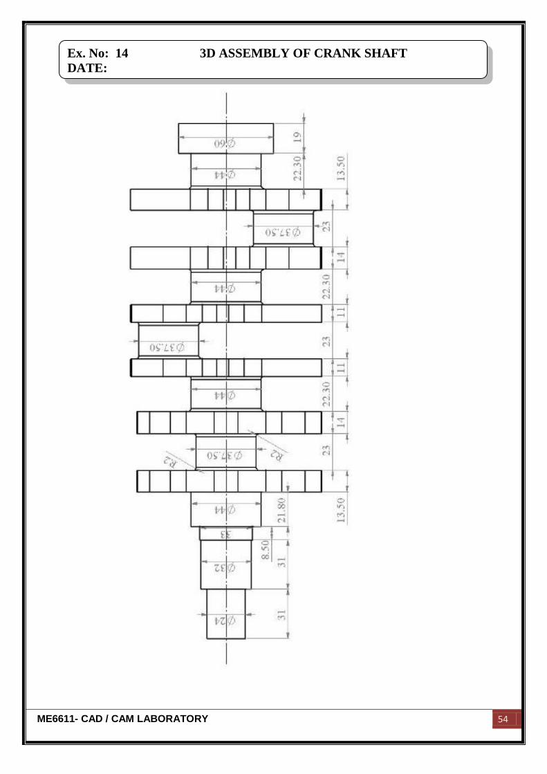
Ex. No: 14 3D ASSEMBLY OF CRANK SHAFT
DATE:
ME6611- CAD / CAM LABORATORY 55
Aim:
To create various parts of crank shaft and assemble them by using standard CAD
software Pro-E.
Hardware required:
250 GB hard disc,8 GB ram, core 2 quad processor, NVIDA graphic card, monitor,
mouse and key board.
Software required:
Pro-E Wildfire 4.0
Description of the component:
A crankshaft is a mechanical part able to perform a conversion between
reciprocating motion and rotational motion. In a reciprocating engine, it translates
reciprocating motion of the piston into rotational motion.
Assembly:
The crankshaft has a linear axis about which it rotates, typically with several bearing
journals riding on replaceable bearings (the main bearings) held in the engine block.
Commands used:
Part diagram:
Extrude → Sketch → Sketch to dimension → Ok
Hole → Sketch → Given dimension → Ok
Revolve → Sketch plane → Sketches → Centerline → Sketch to dimension → Ok
Assembly:
Assembly → Set default → Assembly according to alignment → Fully constrained
→ Ok
Result:
Thus the given various part of crank shaft had been created and assembled by using
standard CAD software Pro-E.
Ex. No: 14 3D ASSEMBLY OF CRANK SHAFT
DATE:
ME6611- CAD / CAM LABORATORY 56
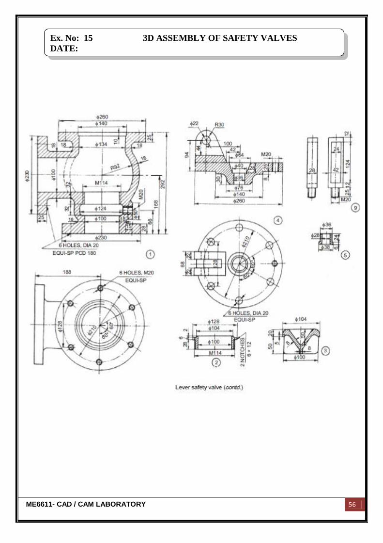
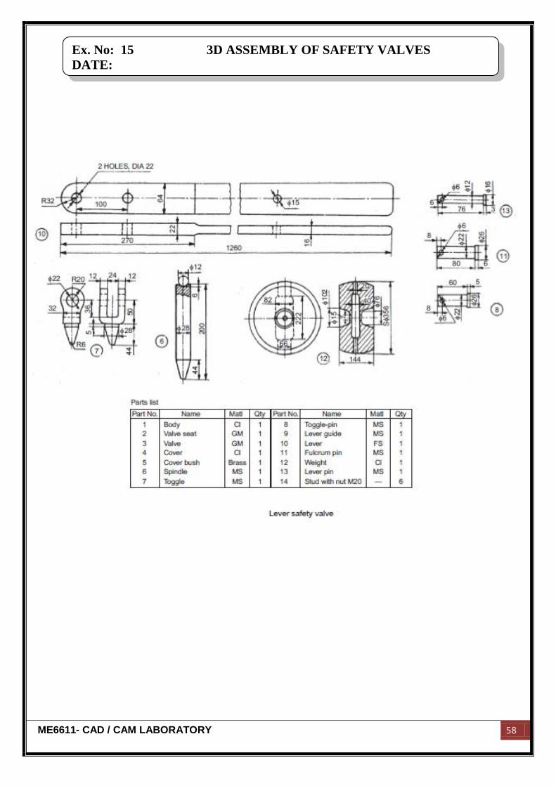
Ex. No: 15 3D ASSEMBLY OF SAFETY VALVES
DATE:
ME6611- CAD / CAM LABORATORY 57
Aim:
To create various parts of safety valves and assemble them by using standard CAD
software Pro-E.
Hardware required:
250 GB hard disc,8 GB ram, core 2 quad processor, NVIDA graphic card, monitor,
mouse and key board.
Software required:
Pro-E Wildfire 4.0
Description of the component:
Safety valves are used to release some of the steam from the boiler when the
pressure rises higher than the safe limit.
Assembly:
The valve seat is screwed in the valve body. The spindle and toggle together keeps
the valve 3 pressed against the seat. The top of the valve body is closed with a cover with
the help of six studs. A cover bush is used to prevent the leakage through the central hole
of the cover. A lever guide is screwed to the cover in order to restrict the lever movement.
The weight is attached to the lever by means of lever pin. The toggle is held in position by
means of toggle pin. Fulcrum pin is used to connect the lever and the cover, to act as the
fulcrum.
Commands used:
Part diagram:
Extrude → Sketch → Sketch to dimension → Ok
Hole → Sketch → Given dimension → Ok
Revolve → Sketch plane → Sketches → Centerline → Sketch to dimension → Ok
Assembly:
Assembly → Set default → Assembly according to alignment → Fully constrained
→ Ok
Ex. No: 15 3D ASSEMBLY OF SAFETY VALVES
DATE:
ME6611- CAD / CAM LABORATORY 58
Ex. No: 15 3D ASSEMBLY OF SAFETY VALVES
DATE:

ME6611- CAD / CAM LABORATORY 59
Result:
Thus the given various part of safety valves had been created and assembled by
using standard CAD software Pro-E.
Ex. No: 15 3D ASSEMBLY OF SAFETY VALVES
DATE:
ME6611- CAD / CAM LABORATORY 60
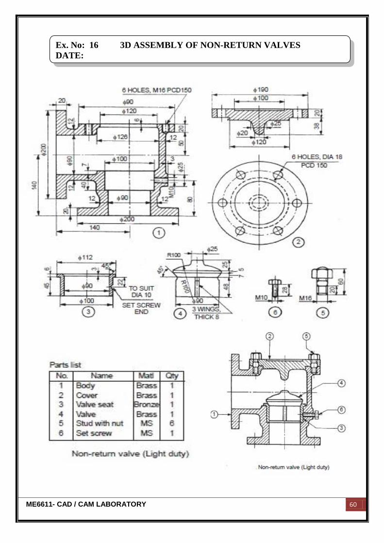
Ex. No: 16 3D ASSEMBLY OF NON-RETURN VALVES
DATE:
ME6611- CAD / CAM LABORATORY 61
Aim:
To create various parts of non-return valves and assemble them by using standard
CAD software Pro-E.
Hardware required:
250 GB hard disc,8 GB ram, core 2 quad processor, NVIDA graphic card, monitor,
mouse and key board.
Software required:
Pro-E Wildfire 4.0
Description of the component:
Valve is a device used for regulating the flow of fluid. In the non-return valve, the
pressure of the fluid allows the flow in one direction only.
Assembly:
It consists of a body with flanges at right angle, for the purpose of mounting the
same. The valve seat is introduced into the body from top and secured in place by set-
screw. The valve is also introduced from top and located in the valve seat. The valve seat
allows free sliding of the valve in it. The studs are first screwed into the body and after
placing the cover, it is tightened with nuts.
Commands used:
Part diagram:
Extrude → Sketch → Sketch to dimension → Ok
Hole → Sketch → Given dimension → Ok
Revolve → Sketch plane → Sketches → Centerline → Sketch to dimension → Ok
Assembly:
Assembly → Set default → Assembly according to alignment → Fully constrained
→ Ok
Result:
Thus the given various part of non-return valves had been created and assembled by
using standard CAD software Pro-E.
Ex. No: 16 3D ASSEMBLY OF NON-RETURN VALVES
DATE:

ME6611- CAD / CAM LABORATORY 62

ME6611- CAD / CAM LABORATORY 63
COMPUTER AIDED
PART PROGRAMMING

ME6611- CAD / CAM LABORATORY 64

ME6611- CAD / CAM LABORATORY 65
STUDY OF CNC MACHINES AND PART PROGRAMMING
Introduction:
CAM:
CAM is a team, which means the Computer Aided Manufacturing. CAM can be
defined, as the use of the computer systems to plan, manage and control the operation of
manufacturing interface with the plant is production resources.
CNC machines:
CNC stands for Computer Numerical Controlled machine is on NC system that
utilizes a delectated stored program computer to perform some are all the basic numerical
control functions. Part programming are entered and stored in computer memory CNC
offers additional flexibility and computation capacity. New system options can be
incorporated into the CNC controller simple by programming the unit.
Classification of CNC machines:
1) MACHINING CENTRE
a) Horizontal spindle machining center
b) Vertical spindle machining center
c) Universal machines.
2) TURNING CENTER CNC LATHES
a) Horizontal machines
b) Chucking machines
c) Shaft machines
d) Universal machines
3) CNC DRILLING AND MILLING MACHINES
4) CNC GRINDING MACHINE
a) Surface grinding
b) Cylindrical grinding
c) Tool and cutter grinder
d) Profile grinder
5) GEAR HOBBING MACHINES
6) PUNCHING AND FORMING MACHINES
ME6611- CAD / CAM LABORATORY 66
Co-ordinate system:
In order for the part programmer to plan the sequence of positions of moments of
the cutting tool. Machine to the WIP, it is memory to establish a standard axis system by
which the relative positions can be specified. Two axis “X & Y” are defined in the plane of
the table, the „z‟ axis in perpendicular. In this plane of the table the vertical motion of the
spindle controls the „z‟ direction. The positive and negative directions motion of the tool.
Programming methods:
1) Incremental method
2) Absolute method
1) Incremental Method:
In this method, every point is considered as origin from this point, the values are
calculated, for example
Point A = (10, 0)
Point B = (20, 0)
Point C = (10, 0)
Point D = (20, 0)
2)Absolute method:
In this absolute system, the set point is considered as a reference point as from that
point, all the values are calculated, for example
Point A = (10, 0)
Point B = (20, 0)
Point C = (30, 0)
Point D = (50, 0)
Programming methods:
In CNC machines program are programmed by two methods.
1) Manual part programming
2) Computer assisted part programming
1) Manual part programming:
To prepare a part program using the manual method, the programmer writes the
machining instruction is must be hence, menu script the instruction is must be prepared in a
ME6611- CAD / CAM LABORATORY 67
very precise manner because the typist prepare the NC type directory from the Manu script
some in various form expending on the machine tool and tape format used.
2) computer assisted part programming:
In the more complicated point and in contour application using manual part
programming because an extremely tedious basic and subject to errors. It is must more
appropriate to employ the high speed digital computer to assist the part programming
languages system have been developed to perform automatically most of the calculation
which the programmer would otherwise be forced to do. It several time and more efficient
part program.
PREPARATORY FUNCTIONS (G-CODE):
Preparatory functions are used for cutting operations like facing, turning, thread
cutting, drilling, etc.,
MISCELLANCEOUS FUNCTIONS (M-CODE) :
Miscellaneous functions are used for other than cutting operations like spindle
ON/OFF, coolant ON/OFF, tool change, etc.,
COMMON G CODES AND M CODES FOR CNC MACHINE CONTROLS
CNC G codes
G00 - Positioning at rapid speed; Mill and Lathe
G01 - Linear interpolation (machining a straight line); Mill and Lathe
G02 - Circular interpolation clockwise (machining arcs); Mill and Lathe
G03 - Circular interpolation, counter clockwise; Mill and Lathe
G04 - Mill and Lathe, Dwell
G09 - Mill and Lathe, Exact stop
G10 - Setting offsets in the program; Mill and Lathe
G12 - Circular pocket milling, clockwise; Mill
G13 - Circular pocket milling, counterclockwise; Mill
G17 - X-Y plane for arc machining; Mill and Lathe with live tooling
G18 - Z-X plane for arc machining; Mill and Lathe with live tooling
G19 - Z-Y plane for arc machining; Mill and Lathe with live tooling
G20 - Inch units; Mill and Lathe
ME6611- CAD / CAM LABORATORY 68
G21 - Metric units; Mill and Lathe
G27 - Reference return check; Mill and Lathe
G28 - Automatic return through reference point; Mill and Lathe
G29 - Move to location through reference point; Mill and Lathe
G31 - Skip function; Mill and Lathe
G32 - Thread cutting; Lathe
G33 - Thread cutting; Mill
G40 - Cancel diameter offset; Mill. Cancel tool nose offset; Lathe
G41 - Cutter compensation left; Mill. Tool nose radius compensation left; Lathe
G42 - Cutter compensation right; Mill. Tool nose radius compensation right; Lathe
G43 - Tool length compensation; Mill
G44 - Tool length compensation cancel; Mill (sometimes G49)
G50 - Set coordinate system and maximum RPM; Lathe
G52 - Local coordinate system setting; Mill and Lathe
G53 - Machine coordinate system setting; Mill and Lathe
G54~G59 - Work piece coordinate system settings #1 to #6; Mill and Lathe
G61 - Exact stop check; Mill and Lathe
G65 - Custom macro call; Mill and Lathe
G70 - Finish cycle; Lathe
G71 - Rough turning cycle; Lathe
G72 - Rough facing cycle; Lathe
G73 - Irregular rough turning cycle; Lathe
G73 - Chip break drilling cycle; Mill
G74 - Left hand tapping; Mill
G74 - Face grooving or chip break drilling; Lathe
G75 - OD groove pecking; Lathe
G76 - Fine boring cycle; Mill
G76 - Threading cycle; Lathe
G80 - Cancel cycles; Mill and Lathe
G81 - Drill cycle; Mill and Lathe
G82 - Drill cycle with dwell; Mill
ME6611- CAD / CAM LABORATORY 69
G83 - Peck drilling cycle; Mill
G84 - Tapping cycle; Mill and Lathe
G85 - Bore in, bore out; Mill and Lathe
G86 - Bore in, rapid out; Mill and Lathe
G87 - Back boring cycle; Mill
G90 - Absolute programming
G91 - Incremental programming
G92 - Reposition origin point; Mill
G92 - Thread cutting cycle; Lathe
G94 - Per minute feed; Mill
G95 - Per revolution feed; Mill
G96 - Constant surface speed control; Lathe
G97 - Constant surface speed cancel
G98 - Per minute feed; Lathe
G99 - Per revolution feed; Lathe
CNC M Codes
M00 - Program stop; Mill and Lathe
M01 - Optional program stop; Lathe and Mill
M02 - Program end; Lathe and Mill
M03 - Spindle on clockwise; Lathe and Mill
M04 - Spindle on counterclockwise; Lathe and Mill
M05 - Spindle off; Lathe and Mill
M06 - Tool change; Mill
M08 - Coolant on; Lathe and Mill
M09 - Coolant off; Lathe and Mill
M30 - Program end, return to start; Lathe and Mill
M97 - Local sub-routine call; Lathe and Mill
M98 - Sub-program call; Lathe and Mill
M99 - End of sub program; Lathe and Mill
ME6611- CAD / CAM LABORATORY 70
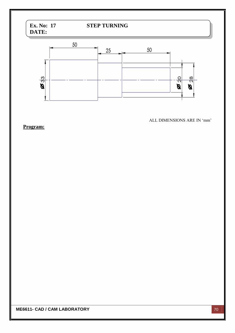
ALL DIMENSIONS ARE IN „mm‟
Program:
Ex. No: 17 STEP TURNING
DATE:
ME6611- CAD / CAM LABORATORY 71
Aim:
To write and simulate part program of the given component for the required
dimensions by using CNC trainer lathe.
Equipment required:
M TAB CNC lathe (FLEXTURN)
Travel x - axis – 95 mm
Travel z - axis – 210 mm
Spindle speed – 150 - 4000 rpm
Tool holder – 8 station ATC
Algorithm:
1. First start the program.
2. Mention the feed rate whether metric or inches.
3. Indicate the reference point.
4. Change the tool for required operation
5. Give the spindle speed.
6. Transverse motion of the tool to x31z1.
7. Give the linear interpolation motion of tool and feed rate.
8. Move the tool in x and z direction to obtain the required size.
9. Move the tool to required point.
10. Stop the program.
Result:
Thus the program for step turning operation is written & simulated by using CNC
trainer lathe.
Ex. No: 17 STEP TURNING
DATE:
ME6611- CAD / CAM LABORATORY 72
ALL DIMENSIONS ARE IN „mm‟
Program:
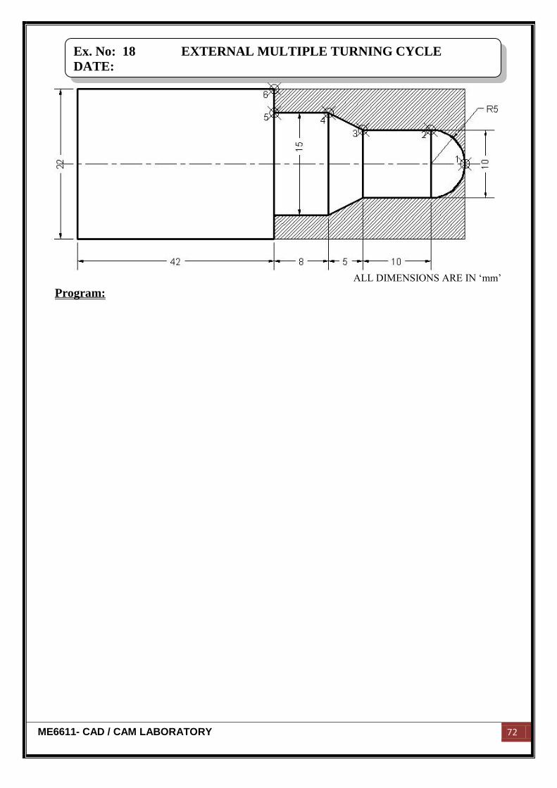
Ex. No: 18 EXTERNAL MULTIPLE TURNING CYCLE
DATE:
ME6611- CAD / CAM LABORATORY 73
Aim:
To write and simulate part program of the given component for the required
dimensions by using CNC trainer lathe.
Equipment required:
M TAB CNC lathe (FLEXTURN)
Travel x - axis – 95 mm
Travel z - axis – 210 mm
Spindle speed – 150 - 4000 rpm
Tool holder – 8 station ATC
Algorithm:
1. First start the program.
2. Mention the feed rate whether metric or inches.
3. Indicate the reference point.
4. Change the tool for required operation
5. Give the spindle speed.
6. Transverse motion of the tool to x31z1.
7. Give the linear interpolation motion of tool and feed rate.
8. Move the tool in x and z direction to obtain the required size.
9. Move the tool to required point.
10. Stop the program.
Result:
Thus the program for external multiple turning operation is written & simulated by
using CNC trainer lathe.
Ex. No: 18 EXTERNAL MULTIPLE TURNING CYCLE
DATE:
ME6611- CAD / CAM LABORATORY 74
ALL DIMENSIONS ARE IN „mm‟
Program:
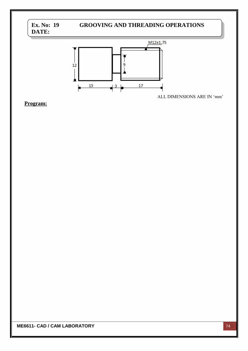
Ex. No: 19 GROOVING AND THREADING OPERATIONS
DATE:

ME6611- CAD / CAM LABORATORY 75
Aim:
To write and simulate part program of the given component for the required
dimensions by using CNC trainer lathe.
Equipment required:
M TAB CNC lathe (FLEXTURN)
Travel x - axis – 95 mm
Travel z - axis – 210 mm
Spindle speed – 150 - 4000 rpm
Tool holder – 8 station ATC
Algorithm:
1. First start the program.
2. Mention the feed rate whether metric or inches.
3. Indicate the reference point.
4. Change the tool for required operation
5. Give the spindle speed.
6. Transverse motion of the tool to x31z1.
7. Give the linear interpolation motion of tool and feed rate.
8. Move the tool in x and z direction to obtain the required size.
9. Move the tool to required point.
10. Stop the program.
Result:
Thus the program for grooving and threading operations are written & simulated by
using CNC trainer lathe.
Ex. No: 19 GROOVING AND THREADING OPERATIONS
DATE:
ME6611- CAD / CAM LABORATORY 76
ALL DIMENSIONS ARE IN „mm‟
Program:
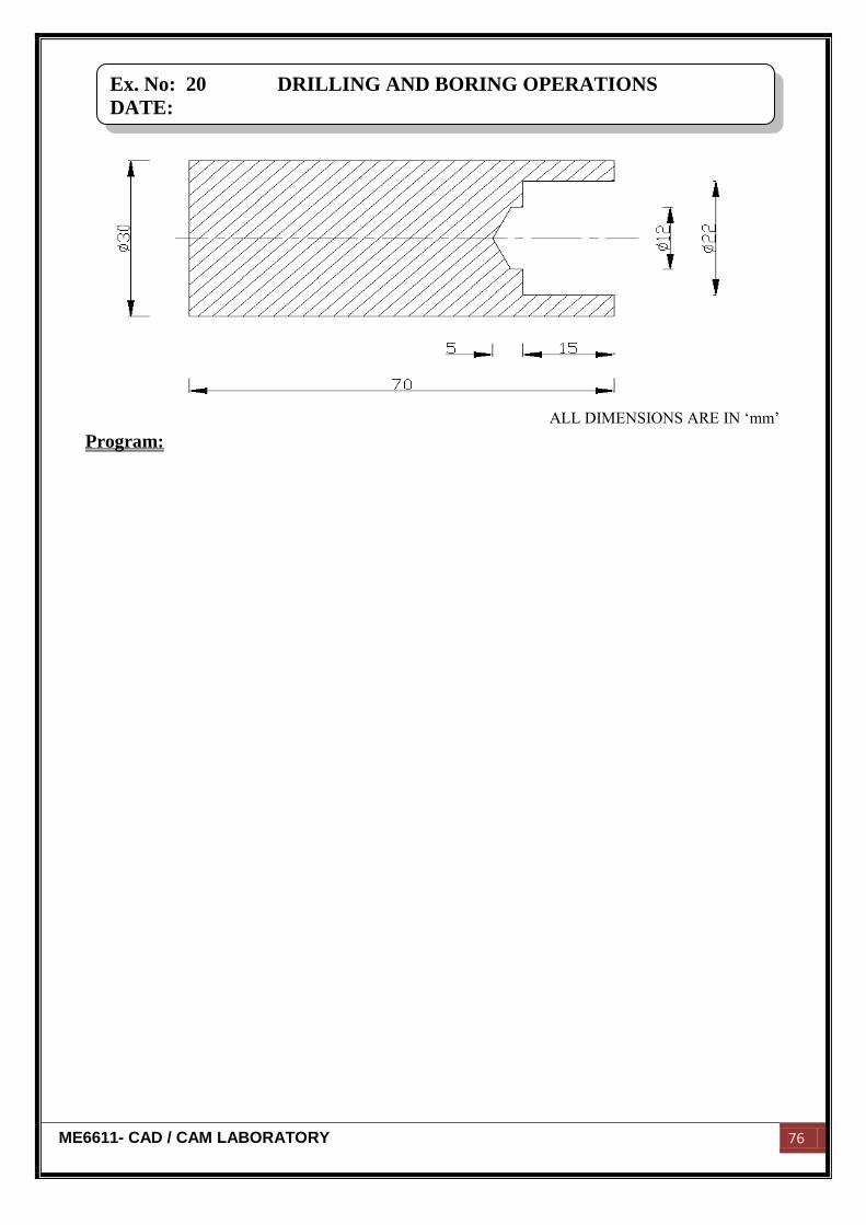
Ex. No: 20 DRILLING AND BORING OPERATIONS
DATE:

ME6611- CAD / CAM LABORATORY 77
Aim:
To write and simulate part program of the given component for the required
dimensions by using CNC trainer lathe.
Equipment required:
M TAB CNC lathe (FLEXTURN)
Travel x - axis – 95 mm
Travel z - axis – 210 mm
Spindle speed – 150 - 4000 rpm
Tool holder – 8 station ATC
Algorithm:
1. First start the program.
2. Mention the feed rate whether metric or inches.
3. Indicate the reference point.
4. Change the tool for required operation
5. Give the spindle speed.
6. Transverse motion of the tool to x31z1.
7. Give the linear interpolation motion of tool and feed rate.
8. Move the tool in x and z direction to obtain the required size.
9. Move the tool to required point.
10. Stop the program.
Result:
Thus the program for drilling and boring operations are written & simulated by
using CNC trainer lathe.
Ex. No: 20 DRILLING AND BORING OPERATIONS
DATE:
ME6611- CAD / CAM LABORATORY 78
ALL DIMENSIONS ARE IN „mm‟
Program:
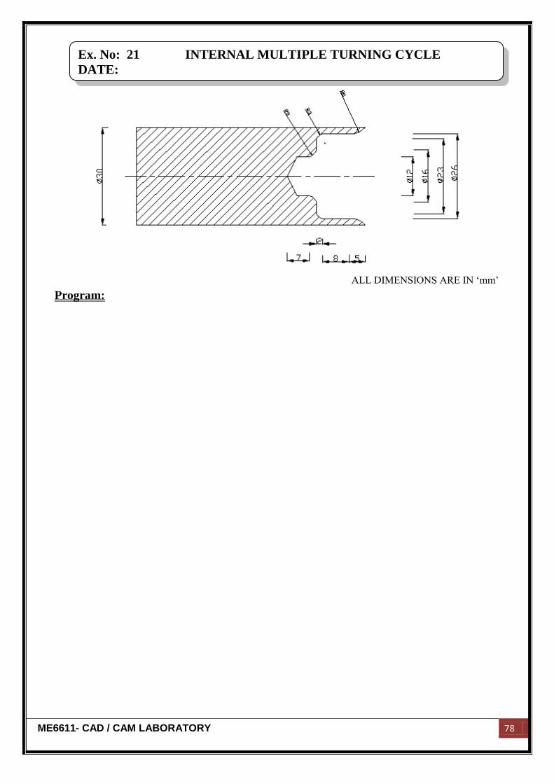
Ex. No: 21 INTERNAL MULTIPLE TURNING CYCLE
DATE:
ME6611- CAD / CAM LABORATORY 79
Aim:
To write and simulate part program of the given component for the required
dimensions by using CNC trainer lathe.
Equipment required:
M TAB CNC lathe (FLEXTURN)
Travel x - axis – 95 mm
Travel z - axis – 210 mm
Spindle speed – 150 - 4000 rpm
Tool holder – 8 station ATC
Algorithm:
1. First start the program.
2. Mention the feed rate whether metric or inches.
3. Indicate the reference point.
4. Change the tool for required operation
5. Give the spindle speed.
6. Transverse motion of the tool to x31z1.
7. Give the linear interpolation motion of tool and feed rate.
8. Move the tool in x and z direction to obtain the required size.
9. Move the tool to required point.
10. Stop the program.
Result:
Thus the program for internal multiple turning operations are written & simulated
by using CNC trainer lathe.
Ex. No: 21 INTERNAL MULTIPLE TURNING CYCLE
DATE:
ME6611- CAD / CAM LABORATORY 80
ALL DIMENSIONS ARE IN „mm‟
Program:
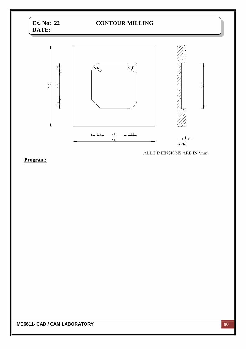
Ex. No: 22 CONTOUR MILLING
DATE:
ME6611- CAD / CAM LABORATORY 81
Aim:
To write and simulate part program of the given component for the required
dimensions by using CNC trainer mill.
Equipment required:
M TAB CNC milling machine (FLEXMILL)
Travel x - axis – 250 mm
Travel y - axis – 150 mm
Travel z - axis – 220 mm
Spindle speed – 150 - 4000 rpm
Tool holder – 8 station ATC
Algorithm:
1. First start the program.
2. Mention the feed rate whether metric or inches.
3. Indicate the reference point.
4. Change the tool for required operation.
5. Give the spindle speed.
6. Transverse motion of the tool to x31z1.
7. Give the linear interpolation motion of tool and feed rate.
8. Move the tool in x and z direction to obtain the required size.
9. Move the tool to required point.
10. Stop the program.
Result:
Thus the program for contour milling is written & simulated by using CNC trainer
Mill.
Ex. No: 22 CONTOUR MILLING
DATE:
ME6611- CAD / CAM LABORATORY 82
ALL DIMENSIONS ARE IN „mm‟
Program:
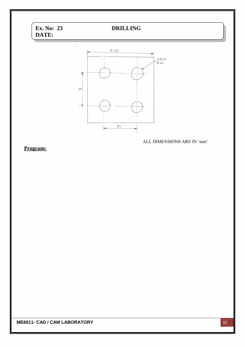
Ex. No: 23 DRILLING
DATE:

ME6611- CAD / CAM LABORATORY 83
Aim:
To write and simulate part program of the given component for the required
dimensions by using CNC trainer mill.
Equipment required:
M TAB CNC milling machine (FLEXMILL)
Travel x - axis – 250 mm
Travel y - axis – 150 mm
Travel z - axis – 220 mm
Spindle speed – 150 - 4000 rpm
Tool holder – 8 station ATC
Algorithm:
1. First start the program.
2. Mention the feed rate whether metric or inches.
3. Indicate the reference point.
4. Change the tool for required operation.
5. Give the spindle speed.
6. Transverse motion of the tool to x31z1.
7. Give the linear interpolation motion of tool and feed rate.
8. Move the tool in x and z direction to obtain the required size.
9. Move the tool to required point.
10. Stop the program.
Result:
Thus the program for drilling operation in milling is written & simulated by using
CNC trainer Mill.
Ex. No: 23 DRILLING
DATE:
ME6611- CAD / CAM LABORATORY 84
ALL DIMENSIONS ARE IN „mm‟
Program:
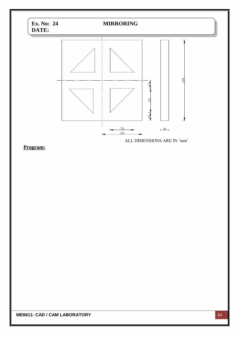
Ex. No: 24 MIRRORING
DATE:

ME6611- CAD / CAM LABORATORY 85
Aim:
To write and simulate part program of the given component for the required
dimensions by using CNC trainer mill.
Equipment required:
M TAB CNC milling machine (FLEXMILL)
Travel x - axis – 250 mm
Travel y - axis – 150 mm
Travel z - axis – 220 mm
Spindle speed – 150 - 4000 rpm
Tool holder – 8 station ATC
Algorithm:
1. First start the program.
2. Mention the feed rate whether metric or inches.
3. Indicate the reference point.
4. Change the tool for required operation.
5. Give the spindle speed.
6. Transverse motion of the tool to x31z1.
7. Give the linear interpolation motion of tool and feed rate.
8. Move the tool in x and z direction to obtain the required size.
9. Move the tool to required point.
10. Stop the program.
Result:
Thus the program for mirroring operation in milling is written & simulated by using
CNC trainer Mill.
Ex. No: 24 MIRRORING
DATE:
ME6611- CAD / CAM LABORATORY 86
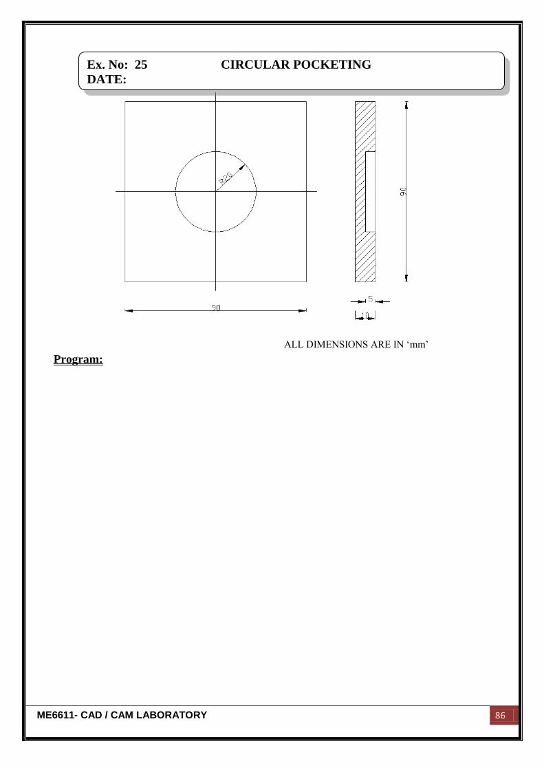
ALL DIMENSIONS ARE IN „mm‟
Program:
Ex. No: 25 CIRCULAR POCKETING
DATE:

ME6611- CAD / CAM LABORATORY 87
Aim:
To write and simulate part program of the given component for the required
dimensions by using CNC trainer mill.
Equipment required:
M TAB CNC milling machine (FLEXMILL)
Travel x - axis – 250 mm
Travel y - axis – 150 mm
Travel z - axis – 220 mm
Spindle speed – 150 - 4000 rpm
Tool holder – 8 station ATC
Algorithm:
1. First start the program.
2. Mention the feed rate whether metric or inches.
3. Indicate the reference point.
4. Change the tool for required operation.
5. Give the spindle speed.
6. Transverse motion of the tool to x31z1.
7. Give the linear interpolation motion of tool and feed rate.
8. Move the tool in x and z direction to obtain the required size.
9. Move the tool to required point.
10. Stop the program.
Result:
Thus the program for circular pocketing in milling is written & simulated by using
CNC trainer Mill.
Ex. No: 25 CIRCULAR POCKETING
DATE: